
g? P ogressEnergy - Florida Public Service Commission
535
ier al Equipment lncorpo Contract #342253 rated ITEI) Executive Summary October l9 2007 ECW L eci __-- Moisture Separator Reheaters (MSRs) QPC ”. I..-...-.- RCA _.- SGR _-C_ br g? P ogressEnergy 1 PEF-NCR-02242 L ,’ >
-
Upload
khangminh22 -
Category
Documents
-
view
2 -
download
0
Transcript of g? P ogressEnergy - Florida Public Service Commission

ier al Equipment lncorpo Contract #342253
rated ITEI)
Executive Summary October l9 2007
ECW L eci __-- Moisture Separator Reheaters (MSRs) QPC ”. I..-...-.-
RCA _.-
SGR _-C_
b r g? P ogressEnergy
1
PEF-NCR-02242
L ,’ >

0
'E I on
0
0
0
0
0
e
e 0
0
Contract Summary tents: Scope of Work Bid Price Comparison Negotiated Savings/Discount Payment Milestones Performance Guarantees Performance Guarantees Based on MWe Warranty
Delivery Liquidated Damages Limits of Liability Project Review Team
TEI Contract Summary Scope of Work:
~~
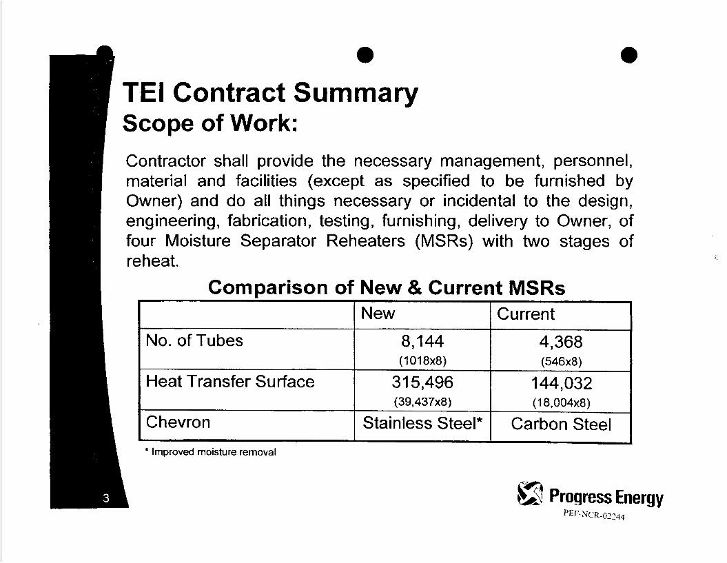
New Current
No. of Tubes 8,144 4,368
Heat Transfer Surface 31 5,496 144,032 (39,437~8) (1 8,004~8)
Chevron Stainless Steel* Carbon Steel
(1 01 8x8) (546x8)
r
Contractor shall provide the necessary management, personnel, material and facilities (except as specified to be furnished by Owner) and do all things necessary or incidental to the design, engineering, fabrication, testing, furnishing, delivery to Owner, of four Moisture Separator Reheaters (MSRs) with two stages of reheat.
Comparison of New & Current MSRs

id
e Contract Summ Price Comparison
ary (000s):
Alstom Siemens
cy-4 Progress Enerw PEF-NCR-02245

TEI Contract Summary Negotiated SavingdPrice (000s):
I Bid
m trc’, 6 $ ProgressEnergy PEF-NCR-02246

TEI Contract Summary Payment M i les tones : a CONFIDENTli?,!.
Milestone Date
Dec 2007
Mar 2008
Oct 2008
Dec 2008
Jan 2009
Jun 2009
Jut 9,2009
Dec 2009
Payment Milestone
Net 60 after order of MSR
Verification Tube Strip material has been ordered for Owner
. Engineering Design Package- Complete ~~~~~~
a Material Receipt provided showing Tube Strip inventoried at
. Tube production: September - October 2008 . True Finning: December 2008 - February 2009
Valtimet
Forgings arrive TEI
Major materials arrive and TEI begins fabrication
TEI receives tubes
MSR Vessels are readied for shipping
. MSR Vessels arrive at Crystal River site, offloaded by TEI and are
Provisional Acceptance - or - 120 days after installation
received without damage
completion, whichever is shorter
Selling Amount Price (000's)
'il) 9 ProgressEnergy h A
PEF-NCR-02247

TEI Contract Summary ~ c o " m n i ; ? ! . Perform a nce
TTD L.P.
TTD H.P. -Fo
AP
M.S. Eff. -%
Note I : Tolerances for measurement of performance parameters will be as follows.
Overall TTD: There will be a 1°F tolerance, so that the penalty starts at I 1 F" and the penalty is to be calculated on "whole" degrees, as measurements will be rounded down to a whole integer.
AP:There will be a quarter pound tolerance, so that the penalty starts at 6.25 PSI
M.S.E.:Tolerance for M.S.E. will be reviewed and mutually approved at a later date. fnstruments readings will be rounded to the nearest integer.
Note 2: Performance will be measured after the 2009 outage and the 201 1 outage. Performance Guarantees will be paid as applicable after each outage but not twice for the same issue.
Note 3: Expect at least 8.0 MWe improvement due to new MSRs. Performance Guarantees penalize up to 2.7 MWe loss and provide no incentive for MWe above the expected 8.0.
Energy PEF-NCR-02248

- PEF-NCR-02249

TEI Contract Summary Delivery Liquidated Damages:
I -5
6-1 I
12-21
Note: Delivery is scheduled for July 30, 2009 Outage start date is September 26, 2009
-3 $m Progress Energy

TED
* Corrective Measure taken to correct the same warranty problem for three (3) times during the Warranty Period (or any extension thereof under the preceding paragraph) hereinafter “Recurring Corrective Measures.” -41
-4 6 G Progress Energy ~EF-NCR-0225 1


e 'El Contract Summ roject Review Team
Project Manager
Project Technical Lead
Legal Tax
Audit Contracts Executive Sponsor
ar
Ted Williams Scott Deahna
Dave Conley Betsy Dorset
Loyd Graves Tony Owen Danny Roderick

3 10375 Sfusher Drive
THERMAL ENGINEERING iNTERNA TIONAL Fe Springs, 90670 IEi MSR TECHNOLOGY AND ADVANCED PROGRAMS DIVISION Fax: ~ m 3 a - b ~ Phone: 323-838-1 150
p .
- ~- . [email protected]
September 14,2007
Progress Energy Florida, Inc Raleigh, NC
Attention: Tony Owen
Subject: CRYSTAL RIVER MSRs CONTRACT - VARIOUS ITEMS
Reference: TEI Proposal 07-M062
Dear Mr. Owen:
This letter confirms the various items discussed on the telephone earlier this aftemoon:
GC-31- Pape 26 of 44
*:* Change - Engineering Design Package Complete -To December 2007
*:* Change - TEI receives tubes -To January 2009
GC-32 - Pace 28 of 44 Subcontracting And Assignment
*:* Contractor shall have the right to subcontract Fabrication Workscope with prior notice to Owner.
Any such subcontracted work will meet all related and applicable specification requirements and
would only be subcontracted to TEl’s approve suppliers with previous MSR experience.
Subcontracting any work will not relieve Contractor of responsibility for the performance of work
in accordance with the Terms and Conditions of this Contract and any amendments executed by
both parties.
GC-36 - nape 33 of 44
Note: Tolerance for the measurement of performance parameters will be as follows:
Overall TTD: There will be a 1°F tolerance, so that the penalty starts at 1 1 Fo and the penalty is to
be calculated on “whole” degrees, as measurements will be rounded down to a
whole integer.
AP:
M.S.:
There will be a quarter pound tolerance, so that the penalty starts at 6.25 PSI.
Tolerance to be determined.

GC-36 - Pape 34 of 44
B. Delivery Liquidated Damages
Insert - "at discretion of Owner" for Owner.
Tony, these are all the items we discussed and TEI is ready to execute this contract next week
Sincerely,
THERMAL ENGINEERING INTERNATIONAL MSR Technology & Advanced Programs Division
Laurence Harma Senior Contracts Manager
LH:no/07-745
PEF-NCR-02256

- MSE Yedonnonce Gunmntee disoosition;
The Drrfmarice mameteis wilt be measured during the 2009 outage. If the MSR's meet the Pcrfontiancr Guarantee values For ll?I. Dclta P and MSE Uicn no Daymen! will he with Iield. A narent Comoanv Guarantcc will be provided bv Contractor IQ covcr potential Performancc Guarantee Daymenw followine the 201 1 refueling
I f the Perfomnnce Guanntecs are not met PS a iesult oPtestine followina thc 2009 rehtelinr outaee. th-flriate L.D.s will be mid. In 201 I. the final Pcrfomiance Guarantee testing will be comoleted and if warranled L.D.s will be paid or remedied as noled a bove.
B. Deliverv Liauidared D amages
Date, Contractor,yifl pay- F. li.9u.[d#d, dUWgF +nd,nOt For each day of unexcused delay in the dclivey of the Work pest the Equipment Dclivery
with the table below not to exceal one million three hundred and fiRy thousand dollars (S I .350,000).
Gc-37
GC- 38
I t is understoa d and w e d that Chvn CT'S dameae for late d>y would be difficult lp determine and hat these amounls me a r e a w b l e cstimatc of Owner's cxpcctcd damam f a latc delivcrv. Anv amo unh not m m o rlv Daid bv h n t m ctm mav bc set off anainst MY iuneunt owed bv Own CT to C- .*... .. WARNING BE(iARDMG S ITE WOW
Thc Contr;lctor is hereby adviscd that thc generadon, tmnsmission and/or distribution of elabical energy involve the handling of a natunl force which, when uncontrolled, is inherently hazardous to life and property. The Contractor is further hereby advised that. doc to !he nature of the Work to be pcrfonncd hereunder, other hamdous or dnngaous conditions (not riecessarily mlatcd IO the inherent danger of electricity) may also be involved in the Work. Accordingly, prior to the cOmmencemcnt of any Work at the Site. the Contractor shall inspect the Sitc specifically to ascerfain the ocr~al and potentinl cxistcncc and extent of any hazardous or dmpcrws conditions, and instruct the Contractor's employees, agents, and Subcontractors with respect to said conditions and Lhc safety measures IO be taken in connection therewith. DuMg the cmm of he Work, h e Conbedor shall Lakc all such mensum 89 may be dcemed necasory or advisoblc to protect nnd safeguard the pason and properly of the Contractor's ond of the general public against all hnznrdous conditions as the same arise.
N O T D
4
I
I I
. . . . . . , . . .. ~ . . ..... . ...... . ..... , , . , . . . . .
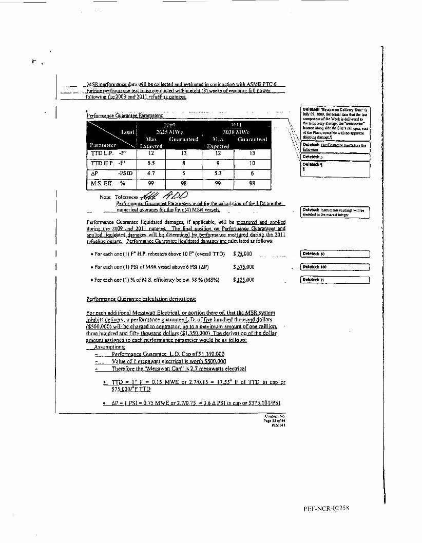
Note: ~ o ~ m n c a & &AB re the
-- nurncrical a v ~ m c e s for tlic four 14) MSR vcsseb . .
P U ~ O ~ M W Guarantee liquidatcd damages, if apphblc, will be d a m durine tlre 2009 imd 2011 outores. Thc final oosition on Pafonilance Guamn tecs and
apes will be dcrmninal hv DL lformance tncnsured durine the: 2 01 1 ctl damaecs arc calmlotad BP follows:
a-&cd darn rcfuelinr OUIPPC. Pcrfomiaticc Gunraritrc I@t . .
For each onc { I ) F' H.P. rcheatm above IO F' (overall TTD) S a 0 0 0 . , , , ... For tach one! (1) PSI of MSR vase1 above 6 PSI (AP)
For tach one ( 1 ) "/o of M.S. efficiency below 98 % (MS%)
$ ~ , O O O
$&,!NO . .
Performance Guarantee calculation derivations;
For each additional Mcrawatt&bical. or Donion there of. that the MSR sWem inhihits dcliverv. a Derf'omnnce marantee L.D. of five hundrcd thousand dollnrv {$500,000) will be charged 10 c o m c t o r . UD to a mnximum amount of one million, - rhrce h d r e d and fih thousand dollers 61.350.000). The derivation of thc dollar pniount assigned to each performance oaramcter would be as follows:
P e d o ~ m c G uarantee L.D. Cap of fl.350.000 Value of I megawatt electrical is worth $50 0.000 Therefore the "Megawatt Can" is 2.7 meqawatts electrical
Assumotions; - -- - -
l T D = I" F = 0.15 MWE or 2.710.15 = 17.55' F of TTD in cao or ~ 5 , O O O P F TTD
AP = J PSI = 0.75 MWE or 2.710.75 = 3.6 A PSI in c a ~ or $37S.OOO/PSI
I Delated: 75 1
PEF-NCR-02258

‘TABLE 1: Payment Milestones
September - Net 60 after order of MSR 10% &&Q - V&ficarion Tube Ship mataial has been
ordered for Owner
November - Engineering Design Package- Complete 10% SJ&lQ 2008 M a h - Material rcseipt provided showing Tube 10% m
Strip inventoried at Valtima - Tube production Sepimbcr - On ZOOS I
I
,$$&/& f d&k?Cwfl@ I
December
I
- Provisional Acceptance - or - 120 days 20% $&!QQ after installation completion withouj -prim uscmsion io IOQ% pwu, whichcver i s m r 9 -
I
I
I - True Finning Dce.2008 - Fcb. 2009 I I October 1 - Forgings orrivc TEI 1 I@?? I-
I _ _ 4 I
Decemba I - Major materials arrive and XI begins
J u l y 2 - MSR Vessels arrive at Crystal Rivcr sit<- .._ . . 1 5 % 52.025, ond Owner T R=dot ... . .. .... .. .. . . . . ._... . . .
B. - Contractor assumes exclusive liability for dl sales or use taxes applicnblc IO my materials, supplies, equipment or tools purchased, rented, leased, used or o t h d s c consumed by Contractor in conjunction with the performance o f the Work.
Owner holds a “Florida S t w n Tax Exemption Affidavit.” This certificate exempts Owncr f“ Florida sales or use tax on purchases of all qualified property and/or labor.
Deleted: JOM 1
,[ Deletedl thao 1
CoDoXI NO. Pyr 26 of 44
t260741
I’EF-NCR-02259

d i m overhead on mployas. Each time slim must be signed by Ownds Dcsignatcd Representative. If any special equipment has ban usd, the invoicz must also specio the equipment used, hours of usage, and rate of reimbursement for use. Owsite Inbor, off-site labor, material, and tquipmcnt MS~S must nppear scparatcly on the invoice.
1. All Work has been completcd and ecceplcd, including outstanding punch list items, final clcanup, tcsting, danobilizntion, and receipt of all required documentation by Owner.
2. A correct invoice covering the Work hng been prcsented to Owner.
A. h Y Q W V Assumna: cloM...!.tiOn..rFPi..a !JY the.CO!ttPC! has been, submitted and approved by Owner.
D. O v e r b i l l i n ~ ~ O ~ s e t s l C r ~ e ~ n d ~
Owner may chargc and colled interest kom the ConmPdor on my overbillings, offsets, credits or rcfunds that may hecome due to Owner under h is Contract. lotem shall be paid nt the rate of the ovcrage primc rote of interest I listed in the Wall Street Joumal Moncy Rates Section. Inlerest shaIl wvm the period of time boom thc date thc oveqnymai, m o r or basis for refund or offsct occurred to the date the amoun~ is paid. The Conrractor may be notificd of the overbilling by credit memorandum or by invoice. Payment of the total overbilling, offsct, credit or refund plus interest shall become due to Owner immcdia\ely upon Contractor's reccipt
GC - 32 SUBCONTRACT7NG AND ASSIGNM
CC-33 INDEMNIFICATION
To thc maximum extent pcrmincd by applicable law, Contractor shall indcmnify and defend Owocr (including i ts parens subsidiary and affiliate companies), its officers, cmployces, ngents, and any olha party with an ownersliip intacst in thc praiiises, hom and against all liability, loss. cos&, claims, damages, expenses, judgments, and awards, whether or not covered by irrsurancc, arising or cloimd to have arisen:
ceavso No.
U260741 PaCc 28 d44
PEF-NCR-02260
10375 Slusher Dnve
THERMAL Fe Springs* '06'0 Phone; 323438-1 IS0
MSR TECHNOLOGY AND ADVANCED PROGRAMS DlVlSlON Fax: 323-838-6154 [email protected]
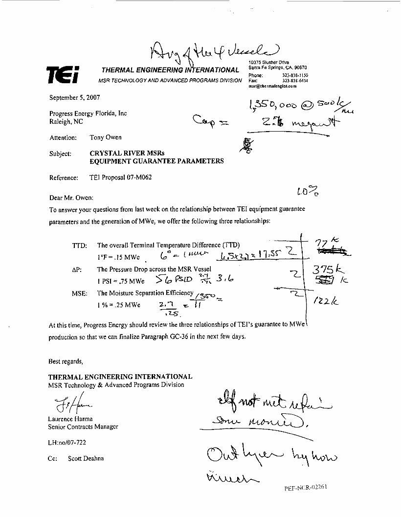
September 5,2007
Progress Energy Florida, Inc Raleigh, NC
4 Attention: Tony Owen \
Subject : CRYSTAL RIVER MSRs EQUIPMENT GUARANTEE PARAMETERS
Reference: TEI Proposal 07-M062
Dear Mr. Owen:
To answcr your questions from last week on the relationship between TEI equipment guarantee
parameters and the generation of MWe, we offer the following three relationships:
TTD: The overall Terminal Temperature Difference (TTD) I°F= -15 MWe ( taw-
AP: The Pressure Drop across the MSR Vessel
1 PSlr .75 MWe $b @lp ?\ 316
0 2 lc -4 J.??.??= MSE: The Moisture Separation Efficiency
211 e !I - 1 % = .25 MWe *ZS.
At this time, Progress Encrgy should review the three relationships of TEl's guarantee to MWe
production so that we can finalize Paragraph GC-36 in the next few days.
Best regards,
THERMAL ENGINEERING INTERNATIONAL MSR Technology & Advanced Programs Division
. s L - L L N44-vim
4 84
Laurence I-larma Senior Contracts Manager
LH:no/07-722
Cc: Scott Deahna
.-
PEF-NCR-0226 I

Message Page 1 of 1
Owen, Tony
From: Deahna, Scott T.
Sent: To: Subject: Crystal River MSRs / Equipment Guarantee Parameters Comments
Wednesday, September 05,2007 10:33 AM Owen, Tony; Williams, Ted E.
The MSR performance sensitivity to megawatts is identified. Ted's previous thought was a loss of 2 megawatts attributable to MSR performance should "triggeC_ahardware remedy. I spoke to Larry Harma last Thursday and Clem Tam yesterday. TEf agrees in Cinuple Mfh the'concept of equipment inspection and remedy if a performance deficiency is identified. You or Larry can draft the appropriate language.
The contract performance guarantee section should identify the tested parameters are an "average of the four MSR vessel performance". However, if any one vessel performance is an out liar, then the performance deficiency of that MSR shall be evaluated by the contractor even if the 2 MW trigger is not met.
1 understand the only additional open item is a preliminary list of engineering deliverables by TEI.
Scott.
-----Original Message----- From: Owen, Tony Sent: Wednesday, September 05,2007 9:44 AM To: Oeahna, Scott T.; Williams, Ted E. Subject: FW: Crystal River MSRs / Equipment Guarantee Parameters
Info requested. The next step is deciding what a Megawatt is worth.
Tony -----Original Message----- From: [email protected] [mailto:[email protected]] Sent: Wednesday, September-05, 2007 9:44 AM To: Owen, Tony Cc: Deahna, Scott T.; [email protected]; [email protected] Subject: Crystal River MSRs / Equipment Guarantee Parameters
Mr. Owen: Please see attached letter from Larry Harma (Equipment Guarantee Parameters) Thank you,
Nicki Executive Assistant Communications Center Thermal Engineering International MSR Technology 8 Advanced Programs Division 10375 Slusher Drive Santa Fe Springs, CA 90670-3748 P: 323.838.1 150 F: 323.838.6454 Email: [email protected]
9/51 2 007

. .
10375 Slusher Drive Santa Fe Springs, CA. 90870 THERMAL ENGINEERING INTERNA TlONAL Phone: 323-838-1 150
MSR TECHNOLOGY AND ADVANCED PROGRAMS DIVISION fax: 323-838-6454 msr@thernmlenginLcoin
November 29 2007
Progress Energy Service Co. LLC 100 E. Davie Street (TPP-08) Raleight, NC 27601
Attention: Mr. Adnen Sunn
Subject: RFP NO. AS-1 2007 For Supplying Two (2) Secondary Plant Component Cooling Water Heat Exchanger (Nos. SCHE-1 N l B ) And Two (2) Condensate Feedwater Heaters (JLP3AIB) For Crystal River Nuclear Power Station
Reference: TEI Proposal 06-M088
Dear Mr. Surin:
TEI is pleased to submit its proposal, in response to your WP No. AS-12007. We trust that we
have adequately covered all aspects of your request.
Should you require additional information, please contact us. We look forward to continuing to be
of service to Progress Energy on tlis very important betterment project.
Very truly yours,
THERMAL ENGINEEFUNG INTERNATIONAL MSR Technology & Advanced Programs Division
A.L. Yarden President
ALY :no/07-923
PEF-NCR-02263

7Ei 7Ei Document Number: 07-924 Proposal Number: 07-M088
A PROPOSAL TO FURNISH
SECONDARY SERVICES CLOSED CYCLE COOLING (SC) HEAT EXCHANGERS
For
CRYSTAL RIVER NUCLEAR POWER STATION UNIT #3
Submitted
To
PROGRESS ENERGY SERVICE COMPANY, LLC
RALEIGH, NC 27601 100 E. DAVIE STREET (TPP-08)
THERMAL ENGINEERING INTERNATIONAL (USA), Inc. (TEI) 10375 SLUSHER DRIVE
SANTA FE SPRINGS, CA 90670-3748
A.L. Yarden President, MSR Technology
& Advanced Programs Division
November 28,2007

TABLE OF CONTENTS
1 . 0 INTRODUCTION
2.0 SPECIAL FEATURES 2.1 Fouling Factors on Tubeside
2.2 Explosive Cladding
2.3 Tube Diameter
2.4 Mechanical Design of the New HXGs
3.0 THERMAL AND MECHANICAL DESIGN
4.0 MANUFACTURING
5.0 PROPOSED OFFER
6.0 COMMERCIAL INFORMATION
6.1
6.2
6.3
6.4 6.5
6.6
6.7
6.8
6.9
6.10
6.1 1
Selling Prices
Taxes
Delivery
Validity
Terms and Conditions
Terms of Payment
Special Condition of Sale . Delays and Damages
Adjustment to Selling Prices
warranty
Force Majeure
Limitation of Liability
....
....
....
....
.. I.
....
..
....
....
....
....
....
....
....
....
....
....
....
....
....
....
Page 1
3
3
4
5
5
6
G 6
G 6
6
7
7
8
8
7.0 ATTACHMENTS
7.1 Outline Drawing
7.2 Specification Sheet 7.3 MSR InstalIation List
....
....
....
....
Page
9 10
11
12

1 .O INTRODUCTION . . Progress Energy Service Company (PESC) is planning to replace a total of two (2) Secondary
Plant Component Closed Cycle Cooling (SC) Heat Exchangers (HXGs) for the Crystal River
Nuclear Power Station (CR) Unit #3. The original SC HXGs were provided by Struthers
Industries, Inc. (now owned by TEI). Due to the power uprate, new HEXs are needed to replace
the existing HXGs, in order to withstand the increased heat duty.
Recently, TEI successfully replaced four (4) CCW HXGs for Kon Nuclear Power Plant, Units #3
and #4 with Titanium tubes. The turnkey job included design, fabrication of the HXGs per ASME
Section III requirements, field installation of the apparatus and the performance test. All the above
operations were done in time and with one hundred percent customer satisfaction. In addition, TEI
has received a contract to provide four (4) TPCW HXGs to San Onofre Nuclear Generation Station
(SONGS) by mid-2009.
Since TEI’s experience is still fiesh (2’004), in conjunction with our partner shop SeDae Kisan
(SDK) in Korea, it is obvious we can do it again to PESC’S expectation.
Following are few special features to highlight TEI’s special design.
2.0 SPECIAL FEATURES
2.1 Fouling Factors on Tubeside
Fouling is time-related, especially in heat transfer equipment. Although the fouling factor
listed in TEMA or other HXG design books is based on years of experience and data from
operation equipment, we find based on our experience that for a new material - for
example titanium - the fouling factor should be reduced. In SONGS, specification, a fairly
conservative cleanliness factor of 0.9 is applied. Ow experience shows that the corrosion
and erosion resistant properties of Titanium are primarily due to the formation of a hard,
tenacious surface oxide film, mainly Titanium dioxide. The film reforms in oxidizing
condition when mechanically damaged. It protects the surface Erom impingement, erosion
and physical damage. It also resists chloride pitting and crevice corrosion by marine
iiiicrobes. Since Titanium tubes resist corrosion, erosion, fouling and scaling, they can
virtually eliminate tubeside fouling. However, in offered design, a cleanliness factor of 0.9
I p ~ ~ - N C R - 0 2 2 6 ~

is still used. This implies that the new HXGs will have much better thermal performance
than expected.
2.2 Explosive Cladding
Titanium can only be welded to titanium; this is a well known characteristics. When
specifying the Titanium tube materia1 in the HXG and with the welded tube joint to the
tubesheet, there is only one option - welded to a Titanium layer which is metallurgically
bound to the carbon steel tubesheet.
Then the tubesheet is machined and drilled to the tolerance. After completely tubing the
HXG, the tube-to-tubesheet joints then are welded by TEI-developed welding procedures,
TEI has utilized this design and manufacture for many non-safety and safety related HXGs
and surface condensers, and has proven the reliability of this technology.
2.3 Tube Diameter
TEI proposes that the new SC HXGs have the same tube diameter of 1” O.D. with 22 BWG
With the same tube diameter as the original HXG, CR can still utilize the existing tube
cleaning system.
2.4 Mechanical Design of the New HXGs
The new SC HXGs are utilizing the same “no tube in window” design. With this design,
TEI is able to fit the tube into the new shell which is only 1 ” larger in outside diameter and
has the same length as the existing HXGs. Additionally, since TEI is the OEM and owns
all the drawings, it is easy for us to fabricate the HXGs to meet the existing connections
without any trouble or concern. In doing so, PESC can rest assured that the new HXGs will fit the existing envelop without any interference concems.
2 P EF-NC R-022 6 8
3.0 THERMAL AND MECHANICAL DESIGN
TEI utilizes the latest version of HTRI program to design the thennohydraulics of the SC HXGs,
HTRI is well known for its conservative and precise thermal correlations especially in the area of
single-phase heat transfer processes. TEI has been a member of HTRI for many years. Our engineering knowledge is original and fbndamental and as such cannot be copied by others.
In HXG design, thermohydraulic and mechanical designs are typically in one which cannot be
separated. The mechanical design is to convert the thermal correlation into a workable equipment
which will perfom under different operating condition to meet the requirement of the system. A
good mechanical design will not only prevent any potential hazard but also take into account the
possible difficult situation such as installation. TEI has performed similar type of work in other
products and gained wide experience. If PESC selects TEI as a Supplier,PESC could be assured of
the high quality and the prompt work schedule.
4.0 MANUFACTURING
TEI is proposing to utilize three options of manufacturing sites. The first one is TEI’s own shop at
Joplin, Missouri. The advantage of Joplin is that the site is located in the USA which allows
PESC’s inspectors relatively easy travel. The second one is our partner-shop (SeDae) in Korea.
The advantage is they have fabricated four (4) Section III CCW HXGs two years ago for Kori
3&4. The third one is our affiliated shop (ARSOPI) located in Portugal, who is fabricating 8 MSR
vessels for Almaraz NPS and 4 LP Feedwater Heaters for KRSKO NPS. All three shops are fully
qualified with good workmanship and with ASME Section VlII Code Stamp and IS0 9000
Certificates.
However, SeDae is a qualified pressure vessel manufacturer who owns additional Section HI,
Class 1,2 and 3 Certificates ofN, NA, NPT. Over time, SDK has developed and qualified its
welding procedures, NDE procedures and manufacturing procedures and has incorporated them
into the Q.A. manual. In the proposed work, SeDae will utilize its capabilities of N-Stamp
qualification to its full extent in performing the shop work.
3

TEI MSR Division is a world class heat exchanger manufacturer specialized in the nuclear power
plant and has years of experience in designing, manufacturing, installing and operating a variety of
HXGs. One of TEI’s prominent specialties is to deal with the complicated installation work where
a limited maneuvering space is available. Therefore, special developed design and fabrication
procedures are needed to surmount the difficulties of the installation. However, these procedures
shall not degrade the integrity of tlie provided equipment as well as the required outage schedule.
5.0 PROPOSED OFFER In this offer, TEI will provide a complete unit of SC HXG. The new HXG has similar shell
diameter to the existing one and meets all the requirements of PESC, such as seismic, tube
vibration, thermohydraulic, latest ASME Code and TEMA, etc. All the large bore connecting
nozzles are matching the existing connections, Internals of the channel will have coating on the
surface of carbon steel. Please refer to the attached data sheet and outline drawings for the offer of
total repIacement.
In responding to PESC’s RFP, TEI has basically followed the outline drawing shown in the
specification to generate the new design which is single pass on both shellside and tubeside. Also,
the configuration of the front and rear channel attachment to the tubesheet is similar to the existing
SC HXGs. However, the channel flange attachment to the tubesheet can be eliminated due to the
Titanium cladding on the tubesheet face.
TEI has attached this optional design of a similar job without the attachment flange to the
tubesheet flange. This approach could totally eliminate the spare channel assembly. If PESC is
interested to do so, TEI will definitely provide an alternative later.
4 PEF-NCR-02270

6. COMMERCIAL INFORMATION The following Sections 6.1 through 6.11 constitute a valid TEI commercial proposal to furnish
PESC with all required hardware, Q.A. documents, engineering analysis and reports in full
compliance with your specifications, industry standards, and other goveming documents. The
scope and features of the design are described in more detail within the technical portion of this
proposal and ih the attached mechanical outline drawings.
6.1 Selling Prices
6.1.1 Proposal
5

.. . 6.2
6.3
6.4
6.5
6.6
6.7
Taxes
The above quoted prices do not include any applicable local sales or use taxes.
Delivery
Delivery is FOB Crystal River NPS. However, PESC is responsible to unload the SC HXGs .
Validity
This proposal is valid for 90 days from its issue date. This date will specifically protect
the quoted prices and the scheduled delivery as shown.
Terms and Conditions
TEI and PESC will mutualIy agree on terms and conditions and all other provisions.
Terms of Payment (J CONFIDENT\!!! REDACTED I
6 PEF-NCR-02272

6.9 Warranty I

6.10 Force Majeure
The Company shall not be in breach of the Contract as a result of any delay in performing
its obligations if such delay is due to strikes or other labor troubles, inability to obtain
raw materials, components, supplies, or bel, for any reason, including default of
suppliers or subcontractor, or any other cause which is beyond the reasonable control of
the Company, whether of a similar or dissimilar nature and whether or not existing or
foreseeable on the date of the Contract or on the scheduled date of commencement of the
work. Should any such delay occur, the time for the performance of the Company’s
obligations shall be extended by a period of time equal to the length of the delay plus
such additional time as is reasonably necessary to enable the Company to resume
performance of its obligations.
Within a reasonable time after the Company becomes aware of a cause entitling it to an
extension of time in accordance with the foregoing paragraph, the Company shall give
notice thereof to the Purchaser. The Company shatl use reasonable efforts to minimize
the delay but shall not be required to subcontract work or to work additional hours for
which premium time is payable or to schedule additional work shifts if such
subcontracting, additional hours or shifts would not have been required to meet the
schedule except for such delay, unless the Purchaser directs that it be done and agrees to
pay all additional charges with respect thereto and provided that the work directed to be
performed is not prohibited by any applicable labor contract or law.
6.1 1 Limitation of Liability
CONFIDENTIF.! 8

7.0 ATTACHMENTS
9

7.1 Outline Drawing
10 PEF-NCR-02276

a CONFIDENTIF.!.

7.2 Specification Sheet
PEF-NCR-02277.A

Page 1 HEAT EXCHANGER SPECIFICATION SHEET US Units
Ei Job No. . ...
istomer PROGRESS ENERGY Reference No. CR3-M-### .&dress Proposal No. 07-M088 Plant Location CRYSTAL RIVER #3 Date 11/20/2007 Rev A
Size 57 x 498 inch Type AEL Horz. Connected In 1 Parallel 1 Series SurWUnit (GrossjEff) 15645.1 / 15503.8 ft2 ShelllUnit 1 SurfIShell (Gross/Eff) 15645.1 115503.8 ft2
PERFORMANCE OF ONE UNIT Fluid Allocation Shell Side Tube Side Fluid Name DM WATER SEA WATER Fluid Quantity, Total Ib/hr 5947600 8178000
Service of Unit SECONDARY SERVICE HEAT EXCHANGER Item No. SCHE-IA & -1 B
Vapor (In/Out) 0.0 0.0 0.0 0.0
Steam 0.0 0.0 0.0 0.0 Water 5947600 5947600 0.0 0.0 Noncondensables 0.0 0.0 0.0 0.0
Specific Gravity 0.9885 0.9918 1.0212 1.0212
Liquid 5947600 5947600 8178000 01 78000
Temperature (In/Out) F 115.00 100.00 90.00 101.75
Viscosity CP 0.5938 0.6916 0.7300 0.7300 Molecular Weight, Vapor Molecular Weight, Noncondensables Specific Heat Btullb-F 0.9978 0.9987 0.9270 0.9270 Thermal Conductivity BtuIhr-A-F 0.3685 0.3660 0.3592 0.3592 Latent Heat Btu/lb 0.0000 0 .oooo 0.0000 0.0000
Velocity Wsec 3.13 5.09
Coulinq Resistance (min) ft2-hr-F/Btu 90% CLEAN 90% CLEAN
t iansfer Rate, Service 500.63 Btulft2-hr-F Clean 561.92 Btu/ft2-hr-F Actual
Inlet Pressure psia 0.000 0.000
Pressure Drop, Allow/Calc psi 18.000 I 13.706 3.300 i 3.181
aat Exchanged Btu/hr 89053665 MTD (Corrected) 11.5 F 505.73 BtuIft2-hr-F
CONSTRUCTION OF ONE SHELL Sketch (BundlelNozzle Orientation) Shell Side Tube Side
Designnest Pressure psig 125 I 1 5 I Design Temperature F 130 120 No Passes per Shell 1 1 (SEE DWG 07-MO88-SC-OIOB) Corrosion Allowance inch
Connections In inch 1 @ 24" 1 @! 3oq Size & Out inch I @224" 1 @ 3 0 Rating Intermediate
TubeNo. 1440 OD 1 inch Thk(Avg) 0.028 inch Length 41.5 ft Pitch 1.25 inch Layout 30 Tube Type Plain Material TITANIUM-GRADE 2 Shell SA-516-70 ID57 inch OD inch Shell Cover N/A
Tubesheet-Sta tionary SA-516-70 W/ TITANIUM CLAD Tubesheet-Floating N/A Floating Head Cover Impingement Plate YES Baffles-Cross Type NTIW-SEG. %Cut (Diam) 15.0 Spacing(c/c) 82.25 Baff les-Long N/A Seal Type N/A Supports-Tube 2 PER SPAN U-Bend N/A Type N/A Bypass Seal Arrangement NIA Tube-Tubesheet Joint Expansion Joint Type Rho-V2-lnlet Nozzle 5315.57 Ib/ft-secZ Bundle Entrance 2392.80 Bundle Exit 1707.50 Ib/ft-sec2 Gaskets-Shell Side Tube Side
Code Requirements TEMA Class Weiq htfShell 44 18 1.6 Filled with Water 102063 Bundle 11374.8 Ib
Channel or Bonnet Channel Cover SA-5 16-70
Inlet 82.25 inch
~ ~~~
-Floating Head -
>marks: 1" TUBES (1) SPARE CHANNEL
I --1

' I 7.3 MSR Installation List
Please refer to LP-3 Feedwater heater attachment.
12
PEF-NCR-02278.A

HEAT EXCHANGER SPECIFICATION SHEET Page 1
Y U B A H E A T T R A N S F E R US Units
I Job No. I Customer PROGRESS ENERGY Reference No. AS-12007 by AD
Address Proposal No. QH-6026-07
Plant Location CRYSTAL RIVER STATION, UNIT 3 Date 1 1 /21/2007 Rev
no. SCHE-1NlB
ILatent Heat I I llnlet Pressure Dsia I I I
IExDansion Joint N/A TvDe I Rho-V2-Inlet Nozzle 5169 86 Ib/fl-secZ Bundle Entrance 1122.1 1 Bundle Exit 885 58 Ib/fl-secZ
Gaskets-Sheil Side N /A Tube Side Non-asbestos
I -Floating Head N/A I ICode Reauirements ASME SEC VIII, OIV 1. TEMA 8 HE1 TEMAClass C I WeighVSheli 57,000 Filled with Water 118,200 Bundle 44,200 ib
Remarks Two supports per span Shell rehef valves
'There are 2 shells total 1 in sewice and 1 in stand-by PEF-NCR-02279
Sacrifical anodes on channel cover
Quick opening manway in channel cover Channel heads to be shipped separately. I Page 1 QG6026 X I S

Yuba Heat Transfer LLC
2121 N. 161' East Avenue A C o m l Tulsa, OK 74116 Limited Partnership 918 234 6000 Company Fax 918 234-3345 wmv.yuba.com
Kanti Shah Manager of Estimating / Sr. Sales Engineer Phone: 918-234-5535
Emal: [email protected] Fax: 918-234-3345
Yuba October 18, 2007
Progress Energy Service Company 100 E. Davie Street (TPP-08) Raleigh, NC 27601
Attention: Mr. Adrien Surin - Sourcing Specialist - NGG Major Projects
Reference: AS-1 2007 Feedwater Heater & Heat Exchanger Replacement Crystal River Nuclear plant Unit 3 Yuba Quote QH-6026-07
Gentlemen:
We are pleased to submit our proposal in response to your November 09,2007 Inquiry. Thank you for selecting Yuba as one of your potential suppliers. Our response to your inquiry represents our best efforts in selecting the design that best suits your needs and using only those designs that have been proven in many applications.
DATA Data describing the proposed equipment (Yuba Feedwater Heater Specification Sheets, dated 11/26/07-and HX dated 11/21/07) has been included for your evaluation and review. We have included technical data and recommended practices for the equipment we are quoting. The design information and recommended practices are the result of knowledge gained during the production of over 6000 feedwater heaters in an environment of continuous improvement and learning. Design and materials of construction shall comply with applicable code and specification requirements for the construction and manufacture of such equipment.
SCOPE OF WORK Our scope of work includes design, fabrication, testing, preparation for shipment, and delivery of subject equipment. Our scope does not include any work for erection or commissioning at site. Assistance from a Yuba Field Service Engineer is available upon request at our Dublished rates (Attached) m CONFIDENTILL

Yuba Heal Transfer LLC
Yuba
2121 N. 161“ East Avenue A Come1 Tulsa, OK 74116 Limiled Partnership 918 234 -6000 Company Fax 918 234-3345 www.yuba.com a CONFIDENTIP,!.
Kanti Shah Manager of Estimating / Sr. Sales Engineer Phone: 918-234-5535 Fax: 918-234-3345 Email: [email protected]
Tube side and shell side relief valves are included in our offering.
VALIDITY Our prices are firm and valid until December 14, 2007. beyond this date, Yuba will verify material costs and provide updated pricing and delivery.
Should your evaluation extend
DELIVERY We will deliver subject equipment FOB job site by 6/15/2009 as required.
TERMS AND CONITIONS Sample contract and terms are for service contract, we are supplying complete equipment so we have not reviewed and not applicable to our equipment. We will be glad to provide our comments if you have different T & C for equipment. We have attached our standard terms of sale for your consideration.
EXCEPTIONS AND CLARIFICATIONS TO SPECIFICATIONS Please refer our response on addendum No. 2 an updated table of conformance in accordance with final version of the specification “Specification for replacement of low pressure closed feedwater heaters and SC for extended power uprate” Our offer is based on this final specification because some requirement for HX has been deleted.
DRAWINGS Setting plan drawings, which provide complete details on purchaser’s connections and supports, will be scheduled for submittal within 60 days after notification of award. We are requesting Progress Energy to limit two (2) weeks turnaround on review of setting plan drawing. We will be more than happy to discuss this matter at your convenience. Should any modifications be desired, drawing submittal will be based on receipt of
complete engineering details at the factory.
2

Yuba Heal Transfer LLC
2121 N. 161s East Avenue Tulsa, OK 74176
Fax 918 234-3345 www.yuba.com
918 234 $000
A Connel Limited Partnership Company
Kanti Shah Manager of Estimating / Sr. Sales Engineer Phone: 9 18-234-5535 Fax: 918-234-3345 Email: [email protected]
Shop detail drawings are considered proprietary in nature and are not submitted. Only a certified setting plan will be transmitted for review. Detailed drawings are always available for review in our Tulsa office where they can be discussed at length with the product engineer assigned to the project.
We will provide the following drawings in the instruction manual for your plant personnel's use: 1. Gasket schedule. 2. Tube layout. 3. Sketch showing location of supports and baffles.
Yuba will submit drawings in electronic format where available. Documents not available in electronic format will be transmitted in paper form.
Yuba's drawings will be per our standard AutoCAD guidelines.
IS0 9001 We would like to highlight that Yuba is certified to IS0 9001. We feel that this is a - - significant step in the continuous improvement process of our Yuba organization and that this will certainly be a benefit to you in our working together to the successful completion of this project.
We appreciate this opportunity to be of service to you on this project. Should we be of additional assistance during your bid evaluation, please feel free to contact us
We look forward working with you on this project.
Very truly yours,
Kanti Shah ICmJ A
cc: Sam R. Naifeh - Vice President of Sales Direct Dial: 91 8-234-5503
3

Message Page 1 of 2
From: Kanti Shah [[email protected]] Sent: Friday, December 07,2007 3:26 PM To: Deahna, Scott T. Cc: Williams, Ted E.; Owen, Tony; Surin, Adrien; Sexton, Larry J.; Sam Naifeh Subject: RE: Yuba Proposal # QH-6026-07 Review Questions and Clarifications Update Gentlemen:
Please find our response to your question in attached document.
For welded Titanium tubes, we will comply all requirements per SB-338-Gr2 only.
For seamless tube we are checking on Ultrasonic testing.(UT).
We do not have response from our supplier regarding price as "buy now"
Thank you for interest in Yuba products.
Best Regards
Kanti Shah Manager of Estimating I Sr. Sales Engineer
YUBA HEAT TRANSFER LLC 2121 N 1 6 1 3 E AVE Tulsa OK 741 16 Phone: 91 8-234-5535 Fax: 918-234-3345 Email: [email protected]
The information transmitted in this facsimile message is intended for the personal and confidential use of only the individual or entity named above, and may contain privileged and confidential information. If the reader of this message is not the intended recipient, you are notified that any dissemination, distribution, copying, retention, or use of this facsimile is strictly prohibited. If you have received this facsimile in error, please notify us by telephone and return the original message to us at the address above via regular mail service (we will reimburse you for your costs). Thank you.
From: Deahna, Scott T. [mailto:[email protected]] Sent: Thursday, December 06, 2007 9:43 AM To: Deahna, Scott T.; Bill Maniss; Kanti Shah Cc: Williams, Ted E.; Owen, Tony; Surin, Adrien; Sexton, Larry 3. Subject: Yuba Proposal # QH-6026-07 Review Questions and Clarifications Update
Gentlemen.
The SC cooler tubes shall be in accordance with the attached ASME SB-338 specification for seamless and welded titanium tubes. Progress Energy prefers seamless tubes as proposed by Yuba. Section 1 1, Nondestructive Tests states seamless tubes require ultrasonic testing (UT) not electromagnetic (EC) testing . The permissible variation in tube dimensions is provided in section 12 and table 5. Yuba should agree to all requirements of ASME 88-338 for seamless tubes.
Thank You, p ~ v - ~ C K - 0 2 2 8 3
file://E:\Response 1 - CR3 (Outcalt) Provided\Yuba\FE Yuba Proposal # QH-6026-07 Clar ... 4/10/2008

Message Page 2 of 2
Scott.
-----Original Message----- From: Deahna, Scott T. Sent: Wednesday, December 05, 2007 7:17 PM To: 'Bill Maniss'; '[email protected]' Cc: Williams, Ted E.; Owen, Tony; Surin, Adrien; Sexton, Larry 3. Subject: Yuba Proposal # QH-6026-07 Review Questions and Clarifications
Bill / Kanti,
Thank You for your timely proposal. I have reviewed your proposal and request your response to the attached technical questions and clarifications.
Thank You, Scott Deahna Lead Engineer, Major Projects Group Crystal River Unit 3 (SA2) Progress Energy 15760 W. Power Line Street Crystal River, FL 34428
cell: (352) 464-7487 [email protected]
(352) 563-2943, ~ 4 2 3 4
02284 pEF - N R -
file://E:\Response 1 - CR3 (Outcalt) Provided\Yuba\RE Yuba Proposal # QH-6026-07 Clar ... 4/10/2008

Pg. 1 of 1 Technical Review of Yuba Proposal 08-6026-07, dated 11/30/07, and Thermal Engineering International Proposal 06-MOSS, dated 11/29/07.
Characteristic : Tube Bundle Size
Technical Review completed by: Scott T. Deahna on 12/07/07. The proposals are for the replacement of two (2) feedwater heaters (CDHE-3A/B) and two (2) secondary plant component cooling heat exchangers (SCHE-1 A/1 B). The heat exchangers are being replaced to support the CR3 extended power uprate project. Progress Energy issued Request for Proposal # AS-12007 on 11/09/07. Draft equipment specifications for the replacement heat exchangers were included with the RFP. A table of conformance to the specification was included with the RFP. The vendor proposals were due on 11/30/07.
Yuba Proposal: TEI Proposal: 57” x 546” 58” x 539”
Summary of Proposals Submitted:
Eff. Surface Heat Exchanged Heat Transfer Rate
The Yuba proposal QH-6026-07 provided the better overall technical design offering. The Yuba proposal includes seamless tubes. The TEI proposal includes seam welded tubes (per telecom w/ Jay Wu). Both types are acceptable per ASME SB-338. Seamless tubes are more expensive. Both vendor proposals were complete and were submitted on time. Both vendors submitted complete table of conformance to the equipment specifications. Both vendors met the technical requirements of the specification. Some exceptions were taken to the specification. None of the exceptions taken to the specification were of technical or commercial significance. The feedwater heater designs submitted by both vendors were essentially technically equivalent. The Yuba SC heat exchanger design provided more heat exchange surface area than the TEI design. The Yuba SC heat exchanger design meets the maximum dimensional requirements. The Yuba SC heat exchanger design provides additional cooling capacity compared to the TEI design.
17,300 Sq. Ft. 295,28 1,000 BtdHr. 1139 Btu/Sa.Ft.-Hr.-F 1165 BtdSa.Ft.-Hr.-F
17,088 Sq. Ft. 294,28 1,000 Btu/Hr.
Vessel Size Tubes (SA-668-TP304L) Design Pressure / Temp Shell Design Pressure / Temp Tubes Vessel Weight
58” OD x 52’- 10” OAL 59” OD x 52’-3” OAL 1000, 0.75”, 0.035”, 45’-6” 75 psig / 280F 400 psig l280F 60,400 Lbs. 60,000 Lbs.
997, 0.75”, 0.035”, 45’ 50 psig / 300F 400 psig / 300F
TTD / DCA I 5 F / 10F I 5F/ 10F

Yuba Heat Transfer LLC
2121 N. 161' Easl Avenue A Connell Tulsa, OK 74116 Lbnied Partnership 918 234 do00 Company
www.pba.com F ~ X 918 234-3345
Kanti Shah Manager of Estimating I Sr. Sale Enginecr Phone: 9 18-234-5535
Email: [email protected] Pax: 918-234-3345
Yuba gpdlvikss December 06,2007
Progress Energy Service Company W S / d g d - 100 E. Davie Street (TPP-08) Raleigh, NC 27601 Wdddyup hflf pr"BL'! Attention: Mr. Adrien Surin - Sourcing Specialist - NGG Majo
Reference: AS-12007 Feedwater Heater & Heat Exchanger Replacement Crystal River Nuclear plant Unit 3 Yuba Quote QH-6026-07
Gentlemen:
Per our conversation we are pleased to provide our offering for welded seam Titanium tubes per SB-338-GR2 for SC. Welded tubes will meet all Code requirements regardless of specification requirement. LP heater tube requirement stays unchanged.
Following offered price is based on buying tubes now and paying for same to avoid escalation.
VAL1 Dl TY Our orices are firm and valid until December 14, 2007. Should your evaluation extend beyoid this date, Yuba will verify material costs and provide updated pricing and delivery.
PAYMENT TERMS
1 f n f ' 0 CONFIDENTIAL. PEF-NCR-02 2 8 6

Yuba Heal Transfer LLC
2121 N. 161'Easl Avenue A Connell Tulsa, OK 74116 Limited Pahenhip 918 234 do00 Company
www.yuba.com F a 918 234-3345
Kanti Shah Manager of Estimating I Sr. Sales Enginecr Phone: 918-234-553s Fax: 918-234-3345 Email: [email protected]
Yuba Except as expressly modified herein, all other stated terms and conditions remain unchanged. We appreciate this opportunity to be of service to you on this project. Should we be of additional assistance during your bid evaluation, please feel free to contact us
We look forward working with you on this project.
Very truly yours,
Kanti Shah
cc: Sam R. Naifeh - Vice President of Sales Direct Dial: 91 8-234-5503
2

Yuba Heat Transfer ProDosal# OH-6026-07 Review Questions and Clarifications:
Yuba Heat Transfer Proposal # QH-6026-07, Feedwater Heater & SC Heat Exchanger Replacement for CR3, Dated October 17,2007.
Please respond or acknowledge the following items pertaining to your proposal and the Progress Energy (PE) bid specification table of conformance exception items.
1) Is the manufacturing quality assurance record submitted to the purchaser?
2) The proposal states vessel outline drawings will be submitted within 60 days of award. Does Yuba agree the CDHE-3A / 3B nozzles should be able to remain in the existing location? Does Yuba agree the SCHE-1 A / 1B nozzles should be able to remain in the existing location except for the tube side sea water connections due to the vessel length increase?
3) What is the SCHE-1A / 1B estimated total length? The SCHE-1A / 1B spec sheet indicates 30” BW connections on the shell side. Does Yuba agree these should be 24” BW?
4) Can Yuba install lifting trunions in the vertical orientation on SCHE-1A / lB? There is a field interference with horizontal orientated tmions.
Table of Conformance Exception Items for SCHE- 1 A / 1 B:
1) 1.1.2.4; Channel Head Epoxy Coating. PE does not accept the coal tar epoxy and will specify a Belzona epoxy product. Is this acceptable to Yuba?
2) 3.2.1; Cathodic Protection. Yuba is not providing. PE would like a zinc anode installed in the channel heads. Is this acceptable to Yuba?
3) 3.2.2; Tube Cleaning System Limits. Yuba will not provide this information. Accepted by PE.
4) 3.2.6; Yuba is providing a carbon steel tubesheet with titanium clad. Tube ends will be welded to the cladding. PE may require epoxy coating on the tube sheet. Is this acceptable to Yuba?
5 ) 3.2.7; SA-5 16-70 shell material is accepted by PE.
6) 3.2.8; Stainless Steel impingement plate at the shell inlet is accepted by PE.
7) 3.2.10; Dissimilar materials in the channel and channel cover (including bolting) shall be electrically isolated by gaskets or non- conducting washers to prevent galvanic erosion. Is this acceptable to Yuba?
8) 3.2.10; PE requests channel cover hinges rather than davits. Is this acceptable to Yuba?
9) 3.2.10; A 20” bolted opening on the channel cover is accepted by PE.
10) 3.6.2; Required Tube Tolerances. Yuba takes exception to the bid specification specific tube measurement tolerance criteria, stating the tube critical characteristics “will be per code”. Provide specific code requirement that Yuba will use for the QC of the 1 inch titanium tubes.
PEF-NCR-0228 8

11) 3.7.2-5; Seamless tubes will be provided. Accepted by PE.
12) 3.9.15-20; NDE of Tubes - Dimensional Measurements. Describe Yuba’s QC program for tube dimensional measurements verification (acceptance criteria per 3 -6.2 above).
13) 3.9.22-46; NDE of Tubes - ECT and UT. Yuba states the tubes will be eddy current tested per code. No UT is required for seamless tubes. Provide specific code requirement that Yuba will use for the ECT of the 1 inch titanium tubes. No UT is accepted by PE.
14) 3.9.47; Tube Chemical and Mechanical Testing. PE will accept submittal of the tube supplier material certification. Is this acceptable to Yuba?
15) 3.9.49; Tube Pressure Testing. What tube pressure testing procedure will Yuba use?
16) 4.9; Bill of Materials. Shop detailed part drawings are not required. PE requests a bill of materials indicating the material specification used for each major part. Is this acceptable to Yuba?
17) 6.3; Subcontractor Approval. Yuba shall be responsible for subcontractor quality control. PE requests Yuba provide a list of subcontractors and their responsibilities after placement of order. Subcontractor approval by PE is not required prior to placement of order. (PE contracts group to acknowledge this item).
Table of Conformance Exception Items for CDHE-3A / 3B:
1) 1.3; Insulation is by PE. Insulation clips may need to be installed on the shell by Yuba as stated in 3.7.13.1. Will Yuba provide stainless steel vent orifice plates?
2) 3.2.13-16; Vessel Seismic Qualification is not required by PE.
3) 3.7.6.4; Tubes to be welded to tubesheet and hydraulically expanded is accepted by PE.
4) 3.7.9.1 and 3.7.9.2; Yuba has an “X” in the conform column. Does Yuba conform “C” to these items?
5) 3.9.2.4; Hydrostatic test exception note is accepted by PE.
6) 3.9.4.3; Finish machining exception note is accepted by PE. Spec states it is not required for LP heaters.
PEF-NCR-02289

Yuba Heat Transfer Proposal # 08-6026-07 Review Questions and Clarifications:
Yuba Heat Transfer Proposal # QH-6026-07, Feedwater Heater & SC Heat Exchanger Replacement for CR3, Dated October 17,2007.
Please respond or acknowledge the following items pertaining to your proposal and the Progress Energy (PE) bid specification table of conformance exception items.
1) Is the manufacturing quality assurance record submitted to the purchaser? Yuba response: Yes
2) The proposal states vessel outline drawings will be submitted within 60 days of award. Does Yuba agree the CDHE-3A / 3B nozzles should be able to remain in the existing location? Does Yuba agree the SCHE-1A / 1B nozzles should be able to remain in the existing location except for the tube side sea water connections due to the vessel length increase?
Yuba response: We are confident that we can keep same but due to increase in length we can not say 100% until we make layout and setting plan drawing.
3) What is the SCHE-1A / 1B estimated total length? The SCHE-1 A / 1B spec sheet indicates 30” BW
Yuba response:
4) Can Yuba install lifting trunions in the vertical orientation on SCHE- 1 A / 1 B? There is a field
Yuba response: Yes we can install conventional vessel lift lugs.
connections on the shell side. Does Yuba agree these should be 24” BW? Yes typo error, we will correct datasheet.
Yuba response: We will comply per specification SB-338-G2.
interference with horizontal orientated trunions.
Table of Conformance Exception Items for SCHE-IA / 1 B:
1) 1.1.2.4; Channel Head Epoxy Coating. PE does not accept the coal tar epoxy and will specify a Belzona epoxy product. Is this acceptable to Yuba? there will be additional cost.
heads. Is this acceptable to Yuba? some additional cost.
Yuba response: It is OK,
2) 3.2.1; Cathodic Protection. Yuba is not providing. PE would like a zinc anode installed in the channel Yuba response: Yes, there will be
3) 3.2.2; Tube Cleaning System Limits. Yuba will not provide this information. Accepted by PE.
4) 3.2.6; Yuba is providing a carbon steel tubesheet with titanium clad. Tube ends will be welded to the
Yuba response: TI clad on TS will cover cladding. PE may require epoxy coating on the tube sheet. Is this acceptable to Yuba?
wetted surface, with gasket surface on the clad . We do not recommend epoxy coating the TI clad.
5 ) 3.2.7; SA-516-70 shell material is accepted by PE.
6) 3.2.8; Stainless Steel impingement plate at the shell inlet is accepted by PE.
7) 3.2.10; Dissimilar materials in the channel and channel cover (including bolting) shall be electrically isolated by gaskets or non- conducting washers to prevent galvanic erosion. Is this acceptable to Yuba?

Yuba response: Yes, we need to do some research and may be some added cost
8) 3.2.10; PE requests channel cover hinges rather than davits. Is this acceptable to Yuba? Yuba response:Yes
9) 3.2.10; A 20” bolted opening on the channel cover is accepted by PE.
10) 3.6.2; Required Tube Tolerances. Yuba takes exception to the bid specification specific tube measurement tolerance criteria, stating the tube critical characteristics “will be per code”. Provide specific code requirement that Yuba will use for the QC of the 1 inch titanium tubes.
Yuba response: We will comply per specification SB-3 3 8-G2.
11) 3.7.2-5; Seamless tubes will be provided. Accepted by PE.
12) 3.9.15-20; NDE of Tubes - Dimensional Measurements. Describe Yuba’s QC program for tube
Yuba response: We will comply per dimensional measurements verification (acceptance criteria per 3.6.2 above).
specification SB-3 3 8-G2.
13) 3.9.22-46; NDE of Tubes - ECT and UT. Yuba states the tubes will be eddy current tested per code. No UT is required for seamless tubes. Provide specific code requirement that Yuba will use for the ECT of the 1 inch titanium tubes. No UT is accepted by PE.
14) 3.9.47; Tube Chemical and Mechanical Testing. PE will accept submittal of the tube supplier material certification. Is this acceptable to Yuba? Yuba response: Yes
15) 3.9.49; Tube Pressure Testing. What tube pressure testing procedure will Yuba use? Yuba response: Hydro test tube & shell side at DP x 1.3 per Code
16) 4.9; Bill of Materials. Shop detailed part drawings are not required. PE requests a bill of materials indicating the material specification used for each major part. Is this acceptable to Yuba?
Yuba response: Yes
17) 6.3; Subcontractor Approval. Yuba shall be responsible for subcontractor quality control. PE requests Yuba provide a list of subcontractors and their responsibilities after placement of order. Subcontractor approval by PE is not required prior to placement of order. (PE contracts group to acknowledge this item). Yuba response: OK. Thank you
Table of Conformance Exception Items for CDHE-3A / 3B:
1) 1.3; Insulation is by PE. Insulation clips may need to be installed on the shell by Yuba as stated in 3.7.13.1. Will Yuba provide stainless steel vent orifice plates? Yuba response: Yes, if required
2) 3.2.13-16; Vessel Seismic Qualification is not required by PE.
3) 3.7.6.4; Tubes to be welded to tubesheet and hydraulically expanded is accepted by PE.
PEF-NCR-0229 1

4) 3.7.9.1 and 3.7.9.2; Yuba has an “X’ in the conform column. Does Yuba conform “C” to these items?
5) 3.9.2.4; Hydrostatic test exception note is accepted by PE. Yuba response: Yes
6) 3.9.4.3; Finish machining exception note is accepted by PE. Spec states it is not required for LP heaters.
PEF-NCR-0229 2

: I
CERTIFfCATE OF AUTHOR 1 ZAT IO N
This certificate accredits tfie named company as authorized to use the indicated symbol of the American Society of Mechanical Engineers (ASME) for the scope of activity shown below in accordance with the appficable rules of the ASME Boiler and Pressure Vessel Code. The use of the Code symbol and the authority granted by this Certificate of Authorization are subject to the provisions of the agreement set forth in the application, Any construction stamped wifh this symbol shall have been built strictly in accordance with the provisions of the ASME Boiler and Pressure Vessel Code.
. COMPANY:
Yuba Heat Transfer 2121 N. f61st East Avenue Tulsa, Oklahoma 74156
SCOPE:
Manufacture of pressure vessels at the above location and field sites controllod by the above location
AUTHORIZED: May2,2007 * I
EXPIRES. June 4,2010
CERTIFICATE NUMBER: I 1 ,578
Chairman of The Boiler And Pressure Vessel Committee
Director, Accreditation and Cer-tifica tion
pEF-NCR-02293

QUALIW MANAGEMRENT SYSTEM - IS0 90011~2000
This is to certitY that
Yuba Heat Tmnser LLC. 21 21 NO. 4 61 ST East Ave Tulsa Oklahoma 74f 16 USA
The design, marketing and manufacture of hedt transfer equipment.
For and on behalf of BSI:
& X P 3 President gS/ Management Systems (Americas)
Originally registered: 02/16/2001 Latest Issue: 06/26/2006 Expiry Date: 06l2512009
Page: 1 of 2
&*ma
This cerlificale remains (lie property ol6SI . Inc. and shall bo returned immediateb upon tho request. An electronic certificate can b authenticated gbleL Printed copies can be validated at www.bs~global.com/CticnlDirecton/ To be read in conjuncfion will1 the a p e above or the allached appendix.
Group Headquarters: 389 Chiwick High Road. London, W4 4AL, UK.
: iji ,.;7! '. '. :;dQ;.xr ' - ")P,'l I Americas Headquarters: 12110 Sunset Hils Road, Suile 200. Reslon, VA 20190, USA. ;;,y:!q:p; y. .;

Connall Llmited Partner8hlp Yuba Hear TraMfer One lnremational phce Boston, MA 021 10
A XSLG20569299 1 010 1107 R
ISAH07981364 1 OIOI 107
COMP. 6250 I I I x 1 COLL. $250
XSuupTJoN O P Q P 6 B A T I O N S I L Q C A T I O ~ C L ~ ~ A L tTEMS RE: EVIDENCE OF INSURANCE
1000000
PEF-NCR-02295

Yuba 2121 N. 161* East Avenue A Connell Heat Tulsa, OK 74116 Limited Partnership Transfer LLC 918 234 4ooo Company - -
F ~ x 918 234-3345 w.yuba.com
Yu ba
REFERENCES NUCLEAR PLANT Russ Wenzel NPPD - COOPER NUCLEAR 402-825-5747
Jeffrey Marion EXELON-PEACH BOTTOM 7 17-456-4696
Peter Omaggioi AMERGEN-TMI 71 7-948-8290
Charlie Zalewski NMC-DUANE ARNOLD 3 19-851 -733 I
Gray Boughman PPL-SUSQ UEHANNA 6 10-774-7673
Bill Cote EXELON-DRESDEN 81 5-41 6-2 I 38
FOSSIL PLANT Alan Tennant Allegheny Energy 724-830-5460
Joe Shelton Southern Company Service 205-992-71 77
Doug Zahn Keyspan 516-545-6281
Patrick Clarke
Leon Gertsch
Tampa Electric Company 8 13-228-4656
Mid American. Energy 71 2-277-5245

I
YUBA HEAT TRANSFER PARTIAL INSTALLATION LET FOR
04Hl83-lA.AMERGEN 03H119-2A'ENTERGY NUCLEAR 03H119-IA'ENTERGY NUCLEAR
02H965-1 CONSTELLATION NUCLEAR 01H939-2 EXELON NUCLEAR 01H939-1 EXELON NUCLEAR 00H862-1 ENTERGY SERVICES, INC 00H865-1 ENTERGY NUCLEAR 99H826-3 ENTERGY SERVICES, INC
99H826-1 ENTERGY SERVICES, INC
99H817-1 ENTERGY SERVICES, INC RIVER BEND
98H748-1 .BOSTON EDISON CO PILGRIM 96H600-3
98H764-1 .NlAGARA MOHAWK POWER 'NINE MILE POINT
NEW YORK POWER AUTHORITY ]JAMES A.
. 961.1600-2 NEW YORKPOWER AUTHORITY .JAMESA. 96H600-1 .NEW YORK POWER AUTHORITY :JAMES A.
. . 94H389 'ENTERGY SERVICES, INC 'ARKANSAS 94H377 NORTHEAST UTILITIES 'MILLSTONE 9 3 ~ 2 3 0 'ENTERGY SERVICES, INC :NINEMILE 91~934 VERMONT YANKEE NUCLEAR POVERNON 89H625 LOUISIANA POWER 8 LIGHT :NINEMILE 89H625 LOUISIANA POWER 8 LIGHT NlNEMlLE 87H330 VIRGINIA ELECTRIC 8 POWER :SURRY 8 7 ~ 3 3 0 VIRGINIA ELECTRIC a POWER SURRY 8 7 ~ 3 3 0 .VIRGINIA ELECTRIC a POWER 'SURRY 87H330 VIRGINIA ELECTRIC &POWER SURRY 85H182 VIRGINIA ELECTRIC 8 POWER SURRY 85H182 VIRGINIA ELECTRIC 8 POWER SURRY 85H181 PACIFlC GAS 8 ELECTRIC 851-1181 PACIFIC GAS 8 ELECTRIC 85H181 PACIFIC GAS 8 ELECTRIC 85H181 PACIFIC GAS &ELECTRIC
.. .
'sflrp $$@ is?- 02-04 i1-04
35-02
:.:.:.:.:.:.
0445
18-03 1002
05-02 01-01 03-01 0440 04-00 04-00 02-00 02-99 1048 04-97 08-97 07-97 01-95 1j-94 10-93 12-91
. .
1049 10-89 0787 12-87 12i7 12-87 07-86 04-86 04-86 05-86
05-86 0586
-
641
183
383.4
848 848 848
1119 1119 1119 -
X X X X X
X
X X X X
, I
'X X X
PEF-NCR-02297 X

YUBA HEAT TRANSFER PARTIAL INSTALLATION LIST FOR
85H180 85H180 85H180 85H986 83H815 83H815 83H815 83H815 83HBt5 83H815 83H815 82H702 80H515 79H412 79H412 79H412 79H412
79H412 79H411 79H411 79H411 79H411 79H411 78H251 78H251
78H251 78H251 78H250 78H250 78H250 78H250 78H250 78H250
PACIFIC GAS 8 ELECTRIC PACIFIC GAS 8 ELECTRIC PACIFIC GAS 8 ELECTRIC LOUISIANA POWER & LIGHT ARKANSAS POWER & LIGHT ARKANSAS POWER 8 LIGHT ARKANSAS POWER 8 LIGHT ARKANSAS POWER 8 LIGHT ARKANSAS POWER 8 LIGHT ARKANSAS POWER a LIGHT ARKANSAS POWER 8 UGH1 NIAGARA MOHAWK POWER
NIAGARA MOHAWK POWER FLORIDA POWER B LlGHT FLORIDA POWER &LIGHT FLORIDA POWER 8 LIGHT FLORIDA POWER 8 LIGHT FLORIDA POWER 8 LIGHT FLORIDA POWER 8 LIGHT FLORIDA POWER 8 LIGHT FLORIDA POWER 8 LIGHT FLORIDA POWER &LIGHT FLORIDA POWER 8 LIGHT TENNESSEE VALLEY AUTHORITY~ELLOW CREEK TENNESSEE VALLEY AUTHORITY YELLOW CREEK TENNESSEE VALLEY AUTH0RITY;YELLOW CREEK TENNESSEE VALLEY AUTHORITY'YELLOW CREEK TENNESSEE VALLEY AUTHORITY YELLOW CREEK TENNESSEE VALLEY AUTHORITY YELLOW CREEK TENNESSEE VALLEY AUTHORITY YELLOW CREEK TENNESSEE VALLEY AUTHORITY3YELCOW CREEK TENNESSEE VALLEY AUTHORITY YELLOW CREEK TENNESSEE VALLEY AUTHORITY YELLOW CREEK
DlABLO CANYON DlABLO CANYON DlABLO CANYON DlABLO CANYON NINEMILE NUCLEAR ONE NUCLEAR ONE NUCLEAR ONE NUCLEAR ONE NUCLEAR ONE NUCLEAR ONE NUCLEAR ONE NINEMILE
NINEMILE ST LUCIE ST LUClE ST LUClE ST LUCIE ST LUClE ST LUCIE ST LUClE
IST LUClE ST LUCIE ST LUCIE
-1 'EH3ABC '14,320 i56 j1538 i 518127'0" j2 ~HUEH ;I 'EH-2ABC :14,120 i53 :lo35 , 518,33'5" !2 !HUEH
5 .EH3 : 19.575' 72i 14621518 !39'4n I2'HUEH
2 :EH-IAB I 13.435: 74; 2224; 518 16'9' !ZiHUH 2 .EH-PA 23,600' 67; 1347j 314 j43'1' i 2'HUH 2 -EH-GAB 2 'EH-5AB i 19,145; 63: 1340: 314 '34'10' j 2/HUH 2 ,EH4AB 13.0101 55; 10221 314 i31'1" j Z(HUH
I I . .
EH-IABC I :27,350 !78 12996 314/25'10' j2 [HUH
118'8' IZ(HUH
!34'0' : I 'ZiHUH
2 .EH-ZAB i 15,130; 1 791 22681314
: 16,1951 60; 1164; 314 I
2 jEH-3AB ' 1 N iEH-t
1 N .EH-1 IN IEH4AB :N !EH-3AB
:N :€H-IAB
IN jEH4AB
I
IN EH-2AB . .
'N -EH-5AB , :
I .
IN iEH-3AB .N IEH-2AB
' 14,025; 57; 10971 314 : 8,535' 44' 830f 518 ~ 8,535! 44; 830j518 .20.067 175 :I974 I ;14,639 :59 1938 ' '15,103 i63 !I478 i20J39 167 '1164 '
i24.325 71 '2193 l20.067 .75 i1974 . 114,639 '59 '938 115,103 /63 j1478 i
31'2' 2lHUH
j30'4' 21HUH 5/8:293' 2 ,HUB 5/8138'3" '2 HUB 314129'7" \2 /HUB
30'4' , 2 p J H
! !
5 1 8 j 4 ~ 9 " j2 !HUB 518132'2" :2 ;HUM 518 ,29 '~ i2 IHUB 518'38'3" j2 !HUB 314 297" :z HUB . ,
,N iEH-lAB /20,739 \67 i l l 6 4 iN iEH-5AB 124,325 I71 i2193 12N iEH4ABC j11.760 157 1773 ' 2 N . . :EHSAEC it2.575 i60 $30 i 2N i iEH-2ABC i22,365 j77 j2294 - 2 N jEH-lABC /22,085 i75 '2308 I1 N IEH-8ABC !12,835 i70 1675 '1 N jEH-7ABC i19.475 '70 11217 -1 N jEH-6ABC !13,825 165 :E41
I t
518143'9" 12 /HUB 3/4:32'2" 12 [HUM
718'31'7' :2 IHUEH
518 27'4" '2 HUH 5/8@2" ' I j2 ,HUEH 718339'3" 12 IHUEH 314'39'8" :2 lHUEH
I W Y 12 'HUEH
718127' 11. i2 'HUH I
1 N jEHSABC '12,550 158 $0 1 ;40'0' 2 iHUEH ' I N EH4ABC '11,760 '57 :773 , 1 131'9.
12 F H 1 N ,EH3ABC ;I2575 $0 $30 7/8131'7* 2 HUEH
178~250 TENNESSEE VALLEY AUTHORITY YELLOW CREEK ,I N ~EH-NBC :21,760 !75 i2217 7 1 8 i 2 ~ 12 [HUH
550 100 SA-268439 850 200 SA-268439 100 450 SA268439 600 180 SA-688-304 (.O5MC) 300 400 SA-686-304L 300 600 SA-688-304L 800 50 SA-688-304 (.05MC) 800 50 SA-688-304 (.05MC) 800 100 SA488304 (.05MC) 800 I 150 SA488304 (.05MC) 8001 300 SA-688-304 (.05MC) !OOO 200 SA-688-304L !OOO 200 SA-688-316L 750 300 SA-588-304 750 751SA-688-304 7501 501SA-588-304
05-86
05-86 09-85
1 09-83 11-83 1 11-83
I 11-83 i 11-83 i 11-83
i 02-81
I 01-80 i
I 09-83
I 12-82 I
I 05-80 !
' 01-80
750 300 SA-688-304 750 75 SA688304 750 50 SA-688-304 750 50 SA488304
1875 424tSA488304L 660 145 SA-249-304 660 275 SA-249-304
2200 355lSA-249304 2200 545 SA-249-304 660 50 SA249304 660 50 SA-249304 6601 501SA-249304
I 660' 65 SA-249-304
660: Z/SA-Z~NO~ 6601 115 SA-249-304
2000' 355 SA-249404
01-80 0 1-80 01-80 11-79 1 1-79 11-79 11-79 11-80 03-80 03-80 0380 03-80 07-79 06-79 07-79 07-79 07-79 09-80 -
j IO84 i 1
1084 i
942 1 I 942 i 942 t
942 ~
I
I
i I j I 1084 ; I
942 ;
942 j
942 :
I
! I I
i I !
350 . i 350 i !
850 550 I 650
890
!
890 i
890 I 890 1375 i
1375
1375 ! 1375 i 1375 1375
1375 I
1375 1375 I 1375 :
X X X X
X X X X X X X X X X
I .
I
1375
PEF-NCR-0229 8

I
YUBA HEAT TRANSFER PARTIAL INSTALLATION LIST FOR
76H108 76H108 75H935 75H935 75H935 75H935 75H935 75H935 75H935 75H934 75H934 75H934 75H934 75H934 75H934 75H934 74H854 74H854 74H854 74H854 74H854 74H854 74H853 74H853 74H853 74H853 74H853 74H853 743.1836 741.1836 74~836 74H836 74H836
BOSTON EDISON CO BOSTON EDISON CO
,PILGRAM NUCLEAR S 2 N IEH6AB PILGRAM NUCLEARS' 2 N iEH-5AB
1 23,350; 861 3191 ' 31,4451 97j 4279
118 J B
PUBLIC SERVICE CO OF INDIANA MARBLE HILL PUBLIC SERVICE CO OF INDIANA MARBLE HILL PUBLIC SERVICE CO OF INDIANA MARBLE HILL PUBLIC SERVICE CO OF INDIANA MARBLE HILL PUBUC SERVICE CO OF INDIANA MARBLE HILL PUBLIC SERVICE CO OF INDIANA MARBLE HILL PUBLIC SERVICE CO OF INDIANA MARBLE HILL PUBLIC SERVICE CO OF INDIANA MARBLE HILL PUBLIC SERVICE CO OF INDIANA MARBLE HILL PUBLIC SERVlCE CO OF INDIANA MARBLE HILL PUBLIC SERVICE CO OF INDIANA MARBLE HILL PUBLIC SERVICE CO OF INDIANA'MARBLE HILL PUBLIC SERVICE CO OF INDlANA MARBLE HILL PUBLIC SERVICE CO OF INDIANA MARBLE HILL PUBLIC SERVICE E8G OF NJ HOPE CREEK PUBLIC SERVICE EBG OF NJ HOPE CREEK PUBLIC SERVICE E8G OF NJ 'HOPE CREEK PUBLIC SERVICE EBG OF NJ HOPE CREEK PUBLlC SERVICE E&G OF NJ HOPE CREEK PUBLIC SERVICE EBG OF NJ HOPE CREEK PUBLIC SERVICE E&G OF NJ HOPE CREEK PUBLIC SERVICE E8G OF NJ HOPE CREEK PUBLIC SERVICE E8G OF NJ HOPE CREEK
PUBLIC SERVICE E&G OF NJ 'HOPE CREEK PUBLIC SERVICE E8G OF NJ HOPE CREEK COMMONWEALTH EDISON CO *BRAIDWOOD COMMONWEALTH EDISON CO BRAIDWOOD COMMONWEALTH EDISON CO BRAIDWOOD COMMONWEALTH EDISON CO BRAIDWOOD COMMONWEALTH EDISON CO BRAIDWOOD
PUBLIC SERVICE E&G OF NJ :HOPE CREEK
12N . . iEH-IABC i13.710 i57 :1201 :2N [EH-ZABC :15,075 $8 1797 :2N lEH-3ABC 113,200 i53 i767 ' 2 N iEH4ABC i12.615 i55 1673 ' 2 N iEH-5AB /22,290 j78 j1842 ' 2N IEH-6AB ;28,110 182 i2037 i 2 N !EHJAB \30,830 187 j3583 :l N :EH-6AB 128,110 !82 12037 '1 N 'EHSAB '22,290 i78 11842 I1 N 'EH4ABC ;12.615 .55 1673 1
' 1 N IEH3ABC 113,200 $3 i767 ' '1 . . N jEH-ZABC j15,075 i58 1797 '
: I N IEH-IABC !13,710 157 11201 j
.2N ;LP-SAEC j18.740 i68 :IO91 I 12N :LP-IIABC :18,880 !68 !IO91 1
i 2 N 'LP-3ABC :25,575 j77 11638 i :2N iLP-2ABC j16,790 64 !IO91 '2 N ILP-IABC '16.310 12N (HP6ABC i17.755 11 N 'LP-5ABC !18,740 :1N 'LP-IIABC ;18,880 i l N ,LPJABC i25.575 177 ;1638 ;1N 'LPaABC !16,790 164 11091 !
'1 N {LP-IABC ji6,3io i67 ita91 I .i N ~HP-GABC 117,755 j e i ; i a i 6 i
I
11 N ;EH-7AB j30.830 i87 13583 I .
. .
'1 N [EHBAB '28,110 182 i2037 i il N 'EHdAB i22.270 178 11842 ! i l N lEH-3ABC -13,200 153 '767 I i l N 'EH-2ABC 115.075 i58 1797 i . I N :EH-lABC j13,710 . . i57 /1201 j
I I I
. . COMMONWEALTH EDISON CO -BRAIDWOOD 74H836 . , I N sEH4ABC 12,615 155 1673 1
1600 600 SA-249404 1600 350 SA249304 850 50 SA-249-304 i 8501 50 SA249304 8501 50 SA-249-304 850 125 I SA-249-304 850 275 SA-249-304 I
850 I 125
850 I
850 400 SA-249-304 24001 5501SA-249304L
8501 400 SA-249404 850 275 SA-249-304
SA249304 850 50 SA-249-304 850 50 SA-249-304 850 50 SA-249-304
2400 500 SA-249-304L 225 SA-249-304
850 125 SA-249-304 850 75 SA-249-304 8501 50 SA-249-304
1 850 125 SA-249-304 GO 75 SA-249-304
850 50 SA-2-249-304 850 50 SA-249-304
1800 425 SA-249-304 850, 400 SA-249304 850 275 SA-249-304 850 50 SA1249304 850 501SA-249-304
Tiip .._. _._._.. . .:.... ..._. ii:u&Ts 09-80 12-77 12-71 08-76 0530 04-80 05-80 05-80 07-80 0680 07-80 03-79 04-79 03-79 03-79 03-79 01-79 03-76
07-78 06-78 10-77 08-77 08-78 10.77 08-77 08-77 12-76 10-76 1.1 -78 06-77 11-77 09-77 11-77 05-77
j 375 i I 1 I I
I
! 1100 j 1100 i 1100 I 1100 .
I
lID0 j ! 1100
1117 1 1117
1 : 1117 ; I
I
i
! 1117 i 1117 1117 j 1117 I 1117 i I
1117 1117
\
I
. . 1117 j 1225
1 1225 :
1225 1225 i 1225 ;
I
1225 I
_ _ .. - . . ~ . .. . . ... . .

YUBA HEAT TRANSFER PARTIAL INSTALLATION LIST FOR
.
74H834 74H834 74H834 74H834 74H834 74H834 74H834 74H831 74H831 74H831 74H831 74H831 74H831 74H830 74H830 74H830 74H830 74H830 74H830 73H800 73H800 73H800 73H800 73H800 73H800 73H800
COMMONWEALTH EDISON CO COMMONWEALTH EDISON CO COMMONWEALTH EDISON CO COMMONWEALTH EDISON CO COMMONWEALTH EDISON CO COMMONWEALTH EDISON GO COMMONWEALTH EDISON CO COMMONWEALTH EDISON CO COMMONWEALTH EDISON CO COMMONWEALTH EDISON CO COMMONWEALTH ED'SON CO COMMONWEALTH EDISON CO COMMONWEALTH EDISON CO COMMONWEALTH EDISON CO COMMONWEALTH EDISON CO MISSISSIPPI POWER 8 LIGHT MISSISSIPPI POWER 8 LIGHT MISSISSIPPI POWER &LIGHT MISSISSIPPI POWER &LIGHT MISSISSIPPI POWER &LIGHT MISSISSIPPI POWER & LIGHT MISSISSIPPI POWER 8 LIGHT MISSISSIPPI POWER &LIGHT MISSISSIPPI POWER 8 LIGHT MISSISSIPPI POWER & LIGHT MISSISSIPPI POWER &LIGHT MISSISSIPPI POWER &LIGHT GULF STATES UTILITIES GULF STATES UTILITIES GULF STATES UTILITIES GULF STATES UTILITIES GULF STATES UTILITIES GULF STATES UTILITIES GULF STATES UTILITIES
850 275 850 I 125 850 50 850 50 850 50
2400 550 800 50
I 8001 50 800 50 800 50
2200 400 2200 150
I 800 5%
800 5d 800 I 50 800 i 50
2200 400 no0 150
600 50 600 100 600 50 600 50 600 100 600 150 600 275
2000 400
BRAIDWOOD BYRON BYRON BY RON BY RON BYRON
.BYRON BYRON BYRON BYRON BYRON BYRON , BY RON BY RON BYRON GRAND GULF GRAND GULF GRAND GULF GRAND GULF GRANO GULF GRAND GULF GRAND GULF GRAND GULF GRAND GULF GRAND GULF GRAND GULF GRAND GULF RIVER BEND RIVER BEND RIVER BEND RIVER BEND RIVER BEND RIVER BEND RIVER BEND
SA-249-304 SA-249-304 SA-249-304 SA-249-304 SA-249-304 SA-249-304 SA-249304 SA-249-304 SA-249-304 SA-249-304 SA-249304 SA-249-304 SA-249-304 SA-249-304 SA-249-304 SA-249-304 SA-249-304 SA-249-304 SA-249-304 (.05MC) SA-249-304 (.05MC) SA-249304 (.05MC) SA-249-304 (.OSMC) SA-249-304 (.05MC) SA-249-304 (.05MC) SA-249-304 (.05MC) SA-249-304 (.O5MC)
:2N IEHGAB 128.110 i82 I ' 12037 ,
i 2 N lEHdA0 ;22,290 \78 ,1842 I
' 2 N ]EH4ABC 112,615 155 j673 ' 2N iEH-3ABC 113,200 i53 '767 : i 2 N !EH-IABC i13.710 1.57 11201 j
' 2 N iEH-7AB i30,830 187 13583
i l N :EHdAB !22,290 178 j1842 ' I N 'EH4ABC j12.615 j55 ;673 .1 N :EHJABC !13,200 !53 i767 .1 N iEH-2ABC i15.075 158 1797 '1 N iEH-IABC '13,710 .57 i1201 : I N EH-7AB j30.830 4 7 13583 I 12N kH-4ABC '12,995 ,55 1779 ' ' 2 N ,EY:3ABC 111,930 i56 ,779 :2N EH-2ABC 113,245 156 1821 ' 2 N jEH-IABC i6,960 150 /416 i 2 N :EH-GAB :40,560 i98 14059 :
I ] 2 N IEH-SAB i32.750 3 7 '3770
I
/ 2 N ;EH-ZAEC 115,075 ' I 158 1797 '
1 N ~EH-GAB 128,110 i82 12037 '
, .
1 N 'EH-4ABC i12,995 i55 1 . 1779 :
1 N iEH3ABC 111,930 3 6 /779 ;
' I N 'EH-kBC i13,245 156 i821 '1 N IEH-IABC 16,960 150 1416 11 N iEHGAB :40,560 '98 j4059 :1 N ,EHSAB i32,750 187 i3770 :l N :--!?AB i1,800 !32 1474 '1 N IEA-7AB j1.780 i32 1474 i l N IEH6AB i20.775 '71 /1700 : I N 'EHSAB 122.310 165 :I671 , '1 N IEH.3AB j14,ZIO j94 j966 '
! I N 'EH4AB 118,000 j61 j1369
: I N :EH-2AB 122,380 171 j1428 i
11-76 1 1-78
518133' 3' f 2 IHUEH 3 1 4 ~ ~ i2 JHUEH
718i4r7. 12 HUEH
3/4!33'v j2 !HUEH 718i24'2- 12 IHUH
314129~ j2 ~HUEH
314138'7' I 12 [HUEH
3/4/46'11" 12 !HUEH
I 518333'3' i2 iHUEH
314133'8' i2 ~HUEH 5/8/24? j2 !HUH
314139'to' 12 ~HUEH 314 3 0 9 ' ,2 iHUEH 314128'3' 12 :HUH 5B124'4' I i2 IHUH 5/8;41'0' i2 lHUEH 314j37'r j2 ~HUEH 314139'10" 12 ~HUEH 3/4;30'9' !2 1HUEH
2 128'5 1;2 \HUH 5/8\244" ;2 HUH 314'14'6" i l IHUEHMlr
1 /35 '10 12 IHUEHM\ 518139'3" !2 iHUEHM\
518136'1' j2 HUEHMW 3/4/38'3' !2 !HUEHMN
1 ! icy 11 /HuEHM\
5/8/35' 2- j2 IHUEHMi
73H800 GULF STATES UTILITIES RIVER BEND
07-77 12-77 04-78 06-78 04-78 04-78 04-78 03-78 07-78
' 08-77 ' 04-77 06-77 09-77 06-77 05-77
i 11-75 11-78 t 125 12-78 ' 125 11-78 I 1251 12-78 i 1251 12-78 ! 125 01-19 1 125
m i;u$li .:.:.:.: . . . _ _.. . . ._. I225 1225 1225 1225 1225 1225 1225 1225 1225 1225 1225 1225 122: 122: 122!
125 125 125 125
99 99
ySFaLip;T{QH 1. .......................... . . , . . . .. . . . . . . . . . . . . . . ..:.:.:.:- . _..____ :.: ._.... ..:.:.::.:.:.:. ._. .:.:.:.:.:.: ....._._ ... . . . . ... _..._.... . . . . . . ._ . , . . . . , . .
I
! j
1 !
i I 1
!
! !
I
I I
!
99 L
991 f 4 I . I I
11-78 . 991 I
I 10-78 991 I 10.18 991 I I
X X X X X X X
X X X
, *X "X X
X X

YUBA HEAT TRANSFER PARTIAL INSTALLATION LIST FOR
73H768 73H768 73H768 73H768 73H768 73H768 71H650 71H650 71H650 71 H650 71H650 71H650 71H649 71H649 71H649 71H649 71H649 71H649 71H615 71H615 71H615 71H615 71H615 71H615 71H614 71H614 71H614 71H614 1713614 PHILADELPHIA ELECTRlC LIMERICK
NORTHEAST UTILITIES NORTHEAST UTILITIES NORTHEAST UTILITIES NORTHEAST UTILITIES NORTHEAST UTILITIES NIAGARA MOHAWK POWER NWGARA MOHAWK POWER NlAGARA MOHAWK POWER NIAGARA MOHAWK POWER NIAGARA MOHAWK POWER NIAGARA MOHAWK POWER GEORGIA POWER CO GEORGIA POWER CO GEORGIA POWER CO GEORGIA POWER CO GEORGIA POWER GO GEORGIA POWER CO
MILESTONE .MILESTONE MILESTONE MILESTONE MILESTONE NINEMILE NINEMlLE NINEMILE NINEMILE NINEMILE NINEMILE EDWIN I HATCH EDWIN I HATCH EDWIN I HATCH EDWIN I HATCH EDWIN I HATCH EDWIN I HATCH
JERSEY CENTRAL POWER 8 LIGF FORKED RIVER
JERSEY CENTRAL POWER a LIGiFORKED RIVER JERSEY CENTRAL POWER a LIGI-'FORKED RIVER JERSEY CENTRAL POWER & LIGk FORKED RIVER
JERSEY CENTRAL POWER B LIG~FORKED RIVER
JERSEY CENTRAL POWER a LIGGFORKED RIVER PHILADELPHIA ELECTRIC LIMERICK PHIUDELPHIA ELECTRIC LIMERICK PHILADELPHIA ELECTRIC LIMERICK PHlLADELPHlA ELECTRC LIMERICK PHILADELPHIA ELECTRIC ,LIMERICK PHILAOELPHIA ELECTRIC LIMERICK PHILADELPHIA ELECTRIC LIMERICK PHILADELPHIA ELECTRIC LIMERICK PHILADELPHIA ELECTRIC LIMERICK PHILADELPHIA ELECTRIC LIMERICK
i 3 N iEH-5ABC 116,500 159 i1163 i3N iEH4ABC ]11.240 i61 is44 !
:3 N jEH-2ABC i13.905 160 1666 '
518i42'1' !2 'HUEH 5/8143'4' ;2 h E H
31444.4' 12 IHUEH
, 3 ~ :EHJABC j16,gzo 164 j933 314144'~1- jz !HUEH
- 3 N . . 'EH-1ABC /25,380 i70 if838 2 N iEH4ABC 10.8951 96: 668
' 2 N !EHJABC i 15.295; 541 1013 ' 2 N iEH:2ABC 18.165; 68' 1125
18,030' 69: 1114 i 2 N EHGABC i 21.395; 66; 1675 iN2 'EH-SAB 15,870 169 i966 tN2 . . iEH4AB !14,555 171 1711 iN2 EH3AB j22.760 176 11930 IN2 'EH-2AB 124,880 $3 12244 jN2 iEH-IAB '12,235 ;75 $79 IN2 iEH-6AE 124,560 j76 i2375 iN1 iEH-5AB '19,565 :72 1925 iN1 IEH-IAB 124,885 173 j1296 ;NI 'EH-3ABC i16.529 f61 i864 'N1 :EH-ZABC :21,575 $4 '987 i N1 iE6-1ABC j12,415 162 . $64 ,- i I
1 2 ~ ~ E H ~ A B C j 16,io5j 64j 980
' 2 N jEH-IABC I I
I
, I . - ' :
12N ;EHJABC . .. . i18,730 . i68 11962 i 2 N 'EH4ABC 117,405 :69 1795 i2 N iEH-3ABC. 122,495 174 11802
2 N IEH-1ABC. !12,535 170 1583 i 2N iEH-6AEC !22,160 169 :2341 -1 N iEH-5ABC. 118,730 i68 11962 '1 N :EH-4ABC i17.405 f69 ;1795
I '1 N :EH-3ABC 122,495 174 11802 :1 N 'EH-2ABC /20,220 170 :I638
- Z N IEH-~ABC i20,220 $8 a ' .
' i
; I N EH-IABC 12,535 170 :583 L
700 50 SA-249-304 700 75 SA-249-304 700 125 SA-249304 700 200 SA249404
1800 500 SA-249404 800 125 SA-249-304 (.05MC) 800 270 SA-249304 (.05MC) 800 75 SA249404 (.05MC) aoo 50 SA-249304 (.05MC) BOO! 50 SA-249404 (.05MC)
ZZOOf 400(8A-249304 (.OMC) 600 225 SA-249404 600 125 SA-249-304 600 100 SA-249404 600 100 SA-249-304 600 100 [SA-249-304
....
12-73 -04i76 _. . .. - . - 01-76 12-75 12-75 - . . 12-75 03-78 03-78 03-78 10-78
. . . .
.. ..
11-78 03-78 04-73 12i72 . . 10-72 i 0.12 12-72
2000 400 SA-249-304 09-72 11 -72
! ' I I 9001 25OiSA-249-304 9001 125iSA-249-304 9001 50\3A-249-304 900 5OjSA-249304 900, I 501SA-249304
21501 550 SA-249-304
I 08-72 700 50 SA-249-304L i 08-72
10-76 10-76 07-76 09-76 05.n
08% 03-73
08-73 06-73
06-73
12-72
10-73
0 1-74
09-72
, .. .
. . . . $@j -L
i7.25 209 209 209 209 I209 I100 li00 I100 1100
I X X X X
!
!
1100
il* 85 i ~
850 i 850 i 850 f
850 , 38.4 1 38.4 1 38.4 1
38.4 i 1161.5; 1161.5[ 1161.51 1161.5/ 1161.51
850 i
850 i
38.4 j . .
X X
!
i !
I
! i 1161.5
1161.5 1161.5
!
! ;
PEF-NCR-0230 ~ 1

YUBA HEAT TRANSFER PARTIAL INSTALLATION LIST FOR
69H496 69H495 69H495 69H495 69H495 69H495 69H476 69H476 69H476 400
MILLSTONE POlP CO MILLSTONE POlP CO MILLSTONE POP CO MILLSTONE POlP CO MILLSTONE POlP CO MILLSTONE POlP CO FLORIDA POWER 8 LIGHT FLORIDA POWER &LIGHT
FLORIDA POWER 8 LIGHT FLORIDA POWER 8 LIGHT LOUISIANA POWER 8 LIGHT LOUISIANA POWER 8. LIGHT LOUISIANA POWER BLIGHT
FLORIDA POWER a LIGHT
LOUISIANA POWER a LIGHT LOUISIANA POWER B LIGHT CONSUMERS POWER CO CONSUMERS POWER CO CONSUMERS POWER CO CONSUMERS POWER CO CAROLINA POWER 8 LIGHT CAROLINA POWER 8 LIGHT CAROLINA POWER 8 LIGHT CAROLINA POWER 8 LIGHT CAROLINA POWER 8 LIGHT CAROLINA POWER a LIGHT
CAROLINA POWER 8 LIGHT CAROLINA POWER 8 LIGHT
CAROLINA POWER 8 LIGHT CAROLINA POWER 8 LlGHT FLORIDA POWER CORP FLORIDA POWER CORP FLORIDA POWER CORP 290 SA-249-304 (.05MC)
MILLSTONE MILLSTONE ,MILLSTONE ,MILLSTONE MILLSTONE MILLSTONE HUTCHINSON HUTCHINSON HUTCHINSON , HUTCHINSON HUTCHINSON NINEMILE NINEMILE NINEMILE NINEMILE NINEMlLE MIDLAND MIDLAND MIDLAND MIDLAND BRUNSWICK BRUNSWICK BRUNSWICK BRUNSWICK BRUNSWICK BRUNSWlCK BRUNSWICK BRUNSWICK BRUNSWICK BRUNSWICK CRYSTAL RIVER CRYSTAL RIVER CRYSTAL RIVER
169H476 FLORIDA POWER CORP
I N 2 'EH-GAB '15.835 169 !I140 ' !N2 :EH-SAB i16.360 '63 :I140 ' ~ N Z : E H ~ A B jN 2 ;EH-JAB I N 2 iEH-2AB
il iEH-3AB '1 'EH-2AB ,I .EH-IAB
: I IEH-5AB . 5 :EH4 ' 5 EH-5
i ~ 2 ~EH-IAB 1 .
. i
11 ~ E H ~ A B
. .
. .
5 IEHII
5 'E!-7 :2 :EH-ZAB i2 /EH-ZAB
I .
, 5 ;EH3
- .
. . ;2 iEHSAB 2 EH-QAB 1 EHJAB
. . . . . . :I ;EH-~AB
14,370 '61 11140 19,990 j58 i l l 4 0 :22.535 i74 )I620 !23,005 ,76 12658 i12.620 !SO !lo72 12.925 163 11072
'18,965 '67 ;lo72 !18,510 172 j1532 21.800 ,71 '1531
1 EH-1AB 1 EHSAB 1 EH4AB 2 EHJAB 2 EH-2A0 ,2 EH-1AB 2 EH-5AB i 2 EHllAB 3 ,EH-1AB 3 EH-2AB 3 EH-5AB
. -
;17.380 168 11627 i24.045 169 12006 i -32.580 $2 j2332
I '
!13,030 i52 :lo76 j16.255 163 !i522 li7,380 168 11627 :24.045 169 .ZOO6
i21.680 (70 '1494 1.13.860 ;55 1800
!32,580 '82 I !2332
%6,865 178 jmo . I
CRYSTALRIVER 3 'EHSAB '13.550 j53 j773 i
518341'0' 12 /HUH
2100 425 SA-249-304L 650 50 ADMIRALTY SB-395 650 50 ADMIRALTY SE-395 650 75 ADMIRALTY 58395 650 150 ADMIRALTY SB-395 650 225 90-10 CuNi
1700 450 80-20 CUNI 750 75 ADMIRALTY SB-395 750 50 ADMIRALTY SB-395 750 50 ADMIRALTY 58395 750 300 96-10 CuNi
1875 425 90-10 CUNI 600 500 SAS56-CZ 600 50 SA-55642
4501 50 SA-249-304 450' 5O(SA-249-304
1300 13001 450 2 2 A , SA-249-304
500 100 SA-249304L 500 50 SA-249304L 500 50 SA 249304L
1700 5501SA;249304L
12-72 07-71 02-72 07-71 07-71 07-71 07-71 03-71 07-71 07-71 07-71 07-71 05-71 05-71 05-71 05-71 05-71 02-72 02-72 02-72 02-72 10-70 01-72 01-72 01-72 05-72 05-72 01-71
5q .?.... $#j - 61.5 165 163 1 3 163 i63 363
350 850 650 050
550 852. 852 852
815 815 815
I
I
815 815 '
815 1
815 , 815 ' 4
815 1 205
860 860 ,
i 4
!
I I
!
. I
I 860 j
PEF-NCR-02302

Y U BA HEAT TRANSFER PARTIAL INSTALLATION LIST FOR
I . .
69H475 69H475 69H475 69H475 69H475 69H469 69H469 69H469 69H469 69H469 68H438 68H438 68H438 68H438 68H438 68H438 68H437 68H437 68H437 68H437 68H437 681-1437 68H416 68H416 68H416 68H416 68H416 68H416 67H394
GEORGIA POWER CO ,EDWIN IHATCH ,N1 .EH4AB '14.220 ;71 11256 ' GEORGIA POWER CO EDWINIHATCH ' N l 'EH3AB '21.870 176 i1836 I GEORGIA POWER CO EDWlN I HATCH ;N1 GEORGIA POWER CO EDWIN I HATCH IN1 GEORGIA POWER CO EDWlN I HATCH N1 NEW YORK POWER AUTHORITY JAMES A. FTTZPATRIC:N NEW YORK POWER AUTHORITY JAMES A. FlTZPATRlCiN NEW YORK POWER AUTHORITY 'JAMES A. FITZPATRIC N NEW YORK POWER AUTHORITY JAMES A FlTZPATRlCiN NEW YORK POWER AUTHORITY 'JAMES A. FITZPATRIC~N BALTIMORE GAS & ELECTRIC BALTIMORE GAS & ELECTRIC BALTIMORE GAS &ELECTRIC BALTIMORE GAS 8 ELECTRIC BALTIMORE GAS 8 ELECTRIC BALTiMORE GAS &ELECTRIC BALTIMORE GAS 8 ELECTRIC BALTIMORE GAS 8 ELECTRIC BALTIMORE GAS 8 ELECTRIC BALTIMORE GAS 8 ELECTRIC BALTIMORE GAS 8 ELECTRIC BALTIMORE GAS &ELECTRIC COMMONWEALTH EDISON CO COMMONWEALTH EDISON CO COMMONWEALTH EDISON CO COMMONWEALTH EDISON CO COMMONWEALTH EDISON CO COMMONWEALTH EDISON CO
CALVERT CLIFFS CALVERT CLIFFS CALVERT CLIFFS CALVERT CLIFFS CALVERT CLIFFS CALVERT CLIFFS CALVERT CLIFFS CALVERT CLIFFS CALVERT CLIFFS CALVERT CLIFFS
12 f2 2 i2 2
CALVERT CLIFFS ,I CALVERT CLIFFS 1 ZION iz ZION '2 ZION 2
ZION 2 ZION ,2
ZION 12
, EH-240 EH-IAB
.EH-5AB ! EHSAB 'EH-5AB EH-2AB EH-1AB EH4AB
24,180 183 1,2230 j12.130 j74 '1174 25,270 '76 12400
'25,314 ! 173 12260 '21.045 167 11240 134,610 190 /2470 !20.720 j66 :I236 120,554 181 j1270
EH-9AB '!12,750 :53 f796
!EHJABC i11.430 154 \880 :EH-IlAB '21,430 :70 j1800 , jEH-IOAB j11.460 i51 i796
:EH-~ABC j10.630 149 ja ia 1
;EH-I~AB j30,115 171 !2006 1 'EHSAB 122,520 j71 I , ,1804
.EH$AB I ,23.&10 168 !I922
:EH4AB 111,975 !65 $40 :EH-3AB ;17,095 [57 :I278 , 'EH-2ABC i13.715 !55 11010 jEH-IABC 110.250 ;60 i892
iEH-5ABC '16.460 j64 )lo60 IEH4AEC '9,965 I50 '717 iEH-JABC 114,185 (55 1832 iEH-2ABC !14,230 '51 1796 jEH-IABC 117,535 164 11535
. .
IEH-GABC j25,025 170 I ,1926
.COMMONWEALTH EDISON co 'ZION :I iEH-5ABC 116,460 i64 11060 j '1 67H394 COMMONWEALTH EDISON CO ZION '1 :EHJABC 114.185 j55 i832 67H394 COMMONWEALTH EDISON CO ZION
67H394 COMMONWEALTH EDISON CO ZION 1 'EH-2ABC 114,230 j57 j796 67H394 COMMONWEALTH EDISON CO ZION :1 :EH-IABC 37,535 \64 :I535
IEH-~ABC j10.095 151 1759 ' 1 '
I .
5 1 8 1 3 ~ 12 HUEHH
314141'3' i2 ~HUEHH 518141'2' 12 ~HUEHH
314138'6' 12 /HUB
I 518i41'8' i2 IHUEHH
314i39 10' 12 IHUEHH 314139'7' 12 :HUB
518!38'10' i 2 :HUB 518134' 10' 12 IHUB 518135'6" 12 iHUB
518136'8' !2 HUB 518135'2' /2 HUB 314139'6" :2 HUB 5181402" 12 !HUB 518135'7' j2 IHUB
518138'4' 12 'HUB 314i34'3' 12 HUB 314142'4' [2 HUB
518344'1' 12 HUMW
314/3v2' '2 ~HUMW
3 / 4 i 4 4 ~ HUB
167~394 COMMONWEALTH EDISON CO :ZION 1 IEH-GABC 125.025 170 11926 3/4/37? 12 IHUMW
000 300 SA-249-304 100 400 SA-249-304 800 250 SA-249-304 800 50 SA-249304 800 50 SA-249-304 800 150 SA-249-304 700l 50 SA-249-304L
3001 501SA-249-304L 3001 ~ O ~ S A - Z ~ ~ - ~ M L
700 225 SA-249-3041 700, I 125 SA-249-304L
700j 75 SA-249304L 3001 50 SA-249304L 3001 50 SA-249304L
650 225'5A-249304L 1500 4751SA-249-304L
650 100 SA-249-304L 650 50 SA-249304L 650 50 SA-249-304L 650 50 SA-249304L
2000 45 SA-249304L 650 225 SA-249304L 650 100 SA-249304L 650 50 SA-249304L 650 50 SA-249304L 650 50 SA-249-304L L 2000 450 SA-249-3041.
16-70 16-70 11-70 11-70 11-70 11-70 38-69. 33-71 33-71
10-70 10-70
05-70 12-70 09-70 09-70 12-70 12-70 12-70 06-70 06-70 06-70 04-70 04-70 04-70 02-71 02-71 02-71 02-71 02-71 08-70 08-70 08-7C 03-7C 03-7[ 03-7( -
860 I 850 850 1 850 i 850 !
I I 149 I i 349 ;
849 : i 849 i
24.351
14.35 1 789
14.35!
14.35 I 14.35 14.35 14.35 14.35 114.35 114.35 114.35 446 1098 1098 1098 1098 1098 531 1098 1098 1098 1098 1098
X X X x j x i
1 !
! i
1
i I
I I I 4
. .
j
X X X X X
X X X X X
I
PEF-NCR-023 03

YUBA HEAT TRANSFER PARTIAL INSTALLATION LIST FOR
67H391 67H391 67H391 67H391 67H391 66H318 66H318 66H318 66H318 66H298 66H298 66H298 66H298 66H277 66H277 66H277 66H277 651-1265 65H265 65H265 65H265 64H191 64H191 64H191 64H191 64H191 64H191 64H191 64H190 64H190 64H190 64H190 64H790
64Hi90 4 1
164H190 FLORIDA POWER &LIGHT TURKEY POINT '1 EH-6 ,11,700 151 :900 , 3/4131'10' i2 IHUMW 1 42001 3501SA-106C
600 600 600 600 450 COMMONWEALTH EDISON co 'QUAD CITIES 12 IEH3ABC 113.640 164 $250 1
COMMONWEALTH EDISON co .QUAD cmis !2 : I iEHZABC i16.480 !78 . I ; '1604 ' COMMONWEALTH EOISON co 'QUAD CITIES '2 IEH-IABC j12,725 $8 12250 .
: I COMMONWEALTH EDISON co :QUAD CITIES i2 iEH-4ABC i11,550 147 i910 '
50 SA-210 50 SA-210 70 SA-210
180 SA-220 75 SA-249-304
COMMONWEALTH EDISON CO COMMONWEALTH EDISON CO COMMONWEALTH EDISON CO COMMONWEALTH EDtSON CO COMMONWEALTH EDISON CO COMMONWEALTH EDISON CO COMMONWEALTH EDISON CO COMMONWEALTH EDISON CO COMMONWEALTH EDISON CO COMMONWEALTH EDISON CO COMMONWEALTH EDISON CO COMMONWEALTH EDISON CO FLORIDA POWER B LIGHT FLORIDA POWER 8 LIGHT FLORIDA POWER a LIGHT FLORIDA POWER 8 LIGHT FLORIDA POWER 8 LIGHT
4501 50 450 50 I800 150 450 50 450 75 4501 50 I 19001 150 450' 50 450 75 450 50
1900 150 450 50 450 75 450 50
1900; 150 460 175 4601 i 100
QUAD CITIES QUAD CITIES QUAD CITIES QUAD CITIES ATOMlC DRESDEN ATOMIC DRESDEN ATOMIC DRESDEN ATOMIC DRESDEN ATOMIC DRESDEN ATOMIC DRESDEN
ATOMIC DRESDEN TURKEY POINT TURKEY POINT TURKEY POINT TURKEY POINT TURKEY POINT
ATOMIC DRESDEN
SA-249-304 SA-249-304 SA-249-304 SA-249-304 SA-249-304 SA-249-304 SA-249-304 SA-249-304L SA-249304L SA-249304L SA-249304L SA-249404 SA-249-304 SA249304 SA-249-304 ADMIRALTY SB-395 ADMIRALTY SB-395
1 1 1 1 3
i3 3 .3 12 2 2 2 2 2
I
i2 2 2
. I
I LOUISIANA POWER &LIGHT NINEMILE LOUISIANA POWER 8 LIGHT .N\NEMILE . 4 iEH-3 i 21.800; 71: 1680: 314 138'0' Z!HUEHH I
: 4 iEH4 14,0401 55! 1026; 3/4 i33 7' i 2 iHUEHH . .
IEH-lABC !12,725 '68 j1250 ;EHJABC l13.640 '64 '1250 tEH-2ABC 116,480 ;78 '1604 iEH4ABC '11.550 ,47 i910 IEH-2ABC ;16,480 i78 :1604 iEH-3ABC '13,640 .64 j1250 'EH-IABC 112,725 j68 i1250 'W-4ABC :11.550 147 is10 ,
EH-1ABC '12,725 ,68 11250 I .EHJABC j13.640 164 11250
. I . 'EH-2ABC i16.480 '78 ,1604 , :EH-4ABC '11,550 147 i910 '
' €Ha ;6,447 .45 i677 j
:EH4 i6,102 '41 1536 '
'EH-3 '4,696 :40 j536 IEH-2 !5,477 i40 i536 .
: .
'EH:~ i .995 ;45 :;e45
. . 5/8;26'4' i4 IHUB ~
314i24'9' i4 IHUB 314124'7" '4 HUB 5/8:37'6" i ! i2 VCDUMW 314i247' !4 I HUB
I I 518!26'4' i4 \HUB
FLORIDA POWER 8 LIGHT TURKEY POINT 2 EH-7 117,355 150 :900 FLORIDA POWER 8. LIGHT TURKEYPOINT 22 'EH-6 '11,700 j51 1900 FLORIDA POWER BLIGHT TURKEY POINT '1 EH-5 i6.447 '45 ,677 FLORIDA POWER 8 LIGHT TURKEY POINT '1 EH-4 6,102 ,41 j536 FLORIDA POWER 8 LIGHT TURKEY POINT .1 EH-3 '4.696 j40 ,536 FLORIDA POWER 8 LIGHT TURKEY POINT 1 EH-2 ,5,477 149 '536
FLORIDA POWER 8 LIGHT 'TURKEY POINT 1 'EH-7 17,355 50 :900 , FLORIDA POWER 8 LIGHT TURKEY POINT 1 'EH-1 '8,995 j45 1845
460 4200 4200
460
460 460 460
4200
460
50 ADMIRALTY 58-395 700 SA-1064 350 SA-1064 175 ADMiRALTY SB-395
- 50 ADMIRALTY SB-395 50 ADMIRALTY SB-395 50 ADMiWLTY SB-395
100 ADMIWLTY SB-395
700 SA-1064
5/8147'1O' :2 314'31'10" (2 3/4123;2' i2
HUMW HUMW. HUB...
04-69
04-69 04-69
05-67 1148
11-68 12-66 12-67 12-67 12-67 12-66 10-67 10-67
05-66 10-66 10-66
04-69.
0489
11-68.
io-67
MW; Ijtitik .:.:.:.. . . . . iii;i;i
33.86 828 828 828
828 828 828
810 810 810
810 81 c
10-66 81C 08-66 I 40; 05-66 !759.' 0566 i759.' 05-66 i759. 05-66 1759. 05-66 '759. 0566 1759. 05-66 1759. 05-65 1759
f
05-65 1759 05-65 ,759
I i
j
I
! f
I
j i
!
! . ! i !
1
I
i ! !
I . . .
! ! L
X X X X
X X X X
X
X X X X X X
.I

YUBA HEAT TRANSFER PARTIAL INSTALLATION LIST FOR
H189 FLORIDA POWER CORP H i m FLORIDA POWER CORP Hi89 FLORIDA POWER CORP
PEF-NCR-02305

- -
(3 LI A I, TT lr .4 SSXJR A NC E P R 0 G RA h.1
The Q.C. Manager is responsible for the administration of the quality program and impleinei~tafion of the provisions of the Coiiipany's Quality Assurance Manual. He reports dii-cclly to the President of the Company and is Chaimlan of the Material Review Board.
All phases of quality assurance plaruiing, inspectioil, noli-con fomiaiices, documei~f control and instrument aiid gauge calibratioll are perfomled i n accordance with fonnaf icistruct ions contained in t fie applicable Qua f i ty Assuraiice Maiiual .
A Shop-Traveler Systein is employed on each job to assure that inspectioris rzqtrjred by the fabricatmi drawings are inade. Verification of each inspection poinf is niade by signing the inspection point 011 the proper traveler by pi-operJy qualified persociael.
Personnel iri\.ol\ed in inspec(ion are trained, lested and cenified to perron11 rion- desti1ictit.e testing. A progain o f continuous traiiiii1g, relestiug and upgrading of irispcctioi1 peisoniiel is in effect
i
I

Yuba Heat Transfer UC
2121 N. 16Is EaslAvenoe A Connefl Tulsa, OK 741 16 Lhnited Partnership 918 234 -WOO Company Fax 918 224-3345 ww.yuba.com
INTERNAL CLEANLINESS PRACTICES EMPLOYED
- -
All internal parts, except for tubes and machined surfaces, are cleaned by blasting with steel grit down to clean metal.
Support plates, etc., are coated with a solution of SYN #1, or equal, to inhibit rust prior to assembly. If rust inhibitors are prohibited by customer's specification, the internal parts are cleaned with a solvent of Lift-Away, DR-60 or equal.
Parts made in advance ofthe time needed for final assembly are carefully placed on pallets and stored on wall shelves or wire baskets in a special area away from the production floor.
On final assembly, all components are inspected and cleaned as required. Particular attention is given to those areas of shells and channel assemblies where debris could be lodged. Hydrotest covers are on all openings at the time of final assembly. This prevents foreign materials entering the unit during fmal assembly and test.
I
When welding of tubes-to-tubesheet is required, special procedures as discussed in the resumes of tube-to-tubesheet attachment; welded tube-to-tubesheet joints are empioyed.
Hydrotests are conducted with clean water, which contains rust inhibitors when required. By special agreement, on stainless steel tube application we can perfo-nn hydrotests with demineralized water.
Test covers are designed to attach to the outside of nozzles and a r e removed with nozzles in the . down position so that no spatter or other debris enters the heater during 'the test cover removal: All openings are immediately capped to assure internal cleanliness.
FACSlMfLE HIE-234-3345

. . . . .....
- -
Our destlperheaters are designed for resistance to \jibi-ation by coiitrollilig the uns~rppo~ted tube spans arid steam veiocifies 111 such B way as to I i n J i t the niaximL1171 tube detlectioi, due lo periodic forces transmittctf fioiii the flowing fluid. Our ntethod o f analysis was developed by Joseph Sebald and is employed in the desigll of \wious types of Ileal exchangers having steam on the shellside, as well as in surface condensers. Our criteria is somewhat more conservative than tlie ividefy used Coilriors Fluidelastic Whirlillg Analysis.
If analysis Is required by customer specifications, for the mosl s e ~ ere f l o ~ conditiotl. such as that caused by the bypassing of an adjacent beater, the velocities withh the btrndle, as well as those in the inlet a ~ i d oiitlet areas, are limited to values that \vould niaintaill vibration aniplitirdes within a Fraction of the tube ligaments. Localized Iiigh velocity region$, caused by maldistribution of flow, are prevented by proper ai~angemenl of the baffles.
Subcooler designs are such that there is a wide margin between tlie rube natural frequency aiid that of the fluctuating flitid forces ar the mosf severe flow condition. The ~irbe natural frequencies are calculated iri accordance with the latest TEMA Edition, whereas the forcing ti-eqtrencies are e\.aluared by the C'heii Method. The central spans ;ind rile inlet and the exit arcas are c.xnrniiied.
PEF-NCR-02308
. . . . . . - .
---------. - . . .. , . ,
..,-....

Most heaters presently jnsll?fled wer'e hililf t( it11 seini-supporr plnte-(J,pe tube srrpports thnt pennitled axial flow o r s t e m through the burid IC, causing lion-coiidensable g ~ s e s to acctimulate af the ends of the s t e m tra\.el \itfiere air vetits \\/ere locared. rlijs Cype of venting system has not been as successftrf in recent years as it origiiially was. This is due to a niiriiber of factors, nniong them, the iiitroductio~i of the short-type subcooliii$ zone. This type of zone requires liiat drains flow toward the tribesheet, while niosl o f f h e steam t h t . Iliroiigh the shell arid bundle is w ' a y fj-om [tie tciheslieel.
As a result, steam arid drains presstire losses are nddirive. 'To pre\:ent ii Iiigli r\'atzr level at the erid of the shell, s t e m pressure loss had to he liniited to one or two iiicltes of' water. requiring low steani velocities around tlie bundle. The use of lowf steanl velocities is inconsistent with venting systems that require reasonably high steam velocities for effectiveness. In addition, this type of venting system was subject to steani-by-passing of the vent connection, reducing vent ff ows from the biundle where the non-condensables tended lo accumulate. Added to these problems, volatiIe feedwater treatment fowd widespread use, leading to concenlration of ammonia, which dissolves tlie protective oxide coating on non-ferrous alloys, accelerating con-osioii, causing copper deposition iri
or her jiarts of die systerii ritid ii,diicing stress-comosion cracking a1 relatively low stress k i d s .
.......... . .......... . . . . . . - .
-_--I
. . .

REV DESCRIPTION DATE Yuba Neat Transfer
CLEANING PWOR TO WELDILNG
Page I of 1
Prior to overlaying tubesheet, clean thoroughly with an acceptable cleaning solution and blow dry with clean shop air.
- -
Before inserting tubes in tubesheet, the tubesheet, tube holes and the end of tubes shall be thoroughly cleaned with cleaning solution and blown dry with clean shop air.
Spray tube holes with an acceptable cleaning solution and blow dry with dean air. It may be necessary to some cases to brush the holes using a brush soaked in an acceptable cleaning solution.
Acceptable cleaning solutions are specified in E 1562.1-55.
. . ..- .- -... . .. .. .^ ... .

Yuba Heal Transfer UG
Yuba
A.
B.
C.
2121 N. 161~EaslAvenue A Come# Tulsa, OK 74116 Limiled Parhenhip 918 234 -6000 Company Fax 918 234-3345 w. yuba.com
TUBE CLEANING WITH FELT PLUGS
- _
When specified on the detail drawings, felt plugs are to be blown through the tubing ID in accordance with this procedure. Tne operation is to take place prior to closing the channel for hydrostatic testing of the channel.
The purpose for using felt plugs is to assure the interior of the tube is free of dirt and dust and is in a condition of cleanliness comparable to that received from the tubing supplier. The acceptance criteria for plugs blown at the completion of fabrication will be plugs that have been blown through the ID of 5 different tubes upon receipt &om the tubing supplier.
The procedure for blowing felt plugs is as follows:
1.
2. 3.
4.
Purge tubing ID with clean, oil-free air. Obtain the number and size of white tube plugs specified on the Bill of Material.
Obtain a tube layout of the unit.
Immediately prior to inserting the plug into the tube, the plug shall be soaked in “Lift-Away”, manufactured by DuBois Chemical Company. a. An acceptable alternate to “Lift-Away” is Dubl-Chek DR-60 Remover,
manufactured by Sherwin Corporation. b. Because of it’s flammable characteristics, acetone is a to be used as a
solvent. Starting in the upper half of the tubesheet, place plugs in each of the tubes in the first row. Do only one row at a time. The tube layout will tell you how many tubes are in a row. Blow the plugs in the first row. Count the plugs blown from the first row. The count ofplugs from the first row must equal the number of tubes shown on the tube layout. If you have lost a plug or portion of a plug, that
. loss is confined to that row. You must locate the’ lost plug($) before proceeding to the next row. Proceed to the next row, repeating the above operation, until ail rows are done.
If the specification calls for a comparison with plugs from the as received tubes from the vendor, proceed as follows using one plug blown at a time.
Insert plugs and blow through tubing using clean, dry, oil-free air.
Immediately following, blow a clean, dry, felt plug through the tube using clean, dry, oil-free air.
ComDare DIUQ to standard plugs obtained upon receipt of tubing.
5.
6. 7.
8.
9.
10
PET-NCR-023 11

Yoba Heat Transfer UC
2121 N. 161dEastAvenue A Cmnell Tulsa, OK 74116 Limited partnership 918 234 Bo00 Cmpany Fax 918 2343345 w.yuba.com
Yu ba SUMMARY OF TUBE-TO-TUBESHEET ATTACHMENT
Rough machined forgings are ultrasonic tested at the mill or on receipt at our shop. When the tubesheet and channel barrel are integral, the tubesheet and comer radius are also color contrast liquid penetrant tested.
The face of the tubesheet is thoroughly cleaned. The forging is preheated.
The tubesheet is overlaid with carbon, stainless steel, Inconel, or Monel depending on the tube material to be applied. Overlay is applied by a submerged arc strip process with each layer being cleaned before starting the next layer.
Find overlay is machined, and the overlay is ultrasonic tested.
Tube holes are drilled, using one of four tape-controlled gun drills.
Two tube hole grooves are machined in the base metal, when required.
Tube holes are chamfered on the face. This chamfer is contained within the final pass of the overlay material and does not extend to underlying passes.
Tube holes are chamfered at the rear of the tubesheet and tie-rod holes are drilled and tapped.
. Supports, nozzles, the skirt section and shrouds are welded in place.
Using a controlled atmosphere furnace, to prevent scale formation, the assembly is post weld heat treated.
The face of the tubesheet and tube holes are mechanically cleaned to be sure of basic cleanliness in these areas.
Final cleaning of tube holes with Dubl-Check is accomplished prior to insertion of tubes.
Note: The practice outlined above is based on metallurgical research and experience in attaching tubes-to-tubesheets. It is subject to modification should there be hrther improvements in the art.
Note: Carbon steel overlay is normaIly used on tubesheets when carbon steel tubes are to be welded.

Yuba neat TransIer LLC
212f N. 161s Easl Avenue A Connell Tuba. OK 74116 Limiled Pwlnerst~hip 916 234 -6000 Company Fax 918 234-3345 w?r.yuba.com
WELDED TUBE-TO-TUBESHEET JOINTS
Tube-to-tubesheet attachments are made in an enclosure. Any air used for cleaning or blowdown is clean and dry.
The enclosed area in which the welding is done is cleaned each shift in which work has been done. All tools, hoses, etc., used in the tube-to-tubesheet weld area are cleaned.
Tube holes and tubes ends are thoroughly cleaned with a solvent, Any scale or adherent surface contamination on tubes is removed from the OD and ID in the weld affected zone prior to cleaning.
Tubes are inserted with ends extended beyond the face of the tubesheet. Tube ends are cleaned with a solvent and dried with clean air. Tubes are then positioned in the approximate final location and the entire face of the tubesheet again washed and dried with clean, dry air. Tubes are finally positioned in the tubesheet.
Filler rod used in the welding process is thoroughly cleaned. All argon used in the Heliarc welding process is passed through a dryer.
The weld affected zone is preheated in accordance with the tube-to-tubesheet welding procedure.
Tube ends are welded with manual or automatic GTAW process, with or without the addition of filler metal. Tube weIds are air soap tested prior to rolling.
Tubes are roIIed; starting back of the weld affected zone in the area of the tube hole grooves and ' extending to the required depth., Rolling is accomplished with an electronically controlled tube
expanding machine, Tube .welds are dye checked after rolling. '
A full shellside hydrostatic test is performed. Test pressure is maintained for specified periods of time. These tests are recorded, if required, and the charts kept as a permanent part of the engineering file.
After the channel closure has been made up, a tubeside hydrostatic test is performed and recorded as outlined above.
The shell and tubeside liydrostatic tests are perfonned in accordance with the requirements of the ASME Code.
Note: The practice outlined above i s based on metallurgical research and experience in the attachment of tube-(0-tubesheets. I t is subject to niodificalion should there be fiirlher irnprovenients in the ails.

2. Bring the shellside test pressure up to the specified psig and hold for a minimum of 30 minutes. Yuba Quality Assurance department wilt witness the pressure gauge for any sign of decrease in pressure during the holding t h e .
Yoba Heat Transfer LLC
2121 N. 16lnEaslAvenue A Connell Tulsa, OK 74116 Limited Parlnership 918 234 -6000 company Fax 918 234.3345 Mm.yubaccm
YUb;a HYDROSTATIC TESTS ON FEEDWATER HEATERS
CODE HYDRO TESTS The purpose of a hydrostatic test is to insure that the design, materials and fabrication methods provide a safe structure. Despite the safeguards employed, deficiencies in any one of these areas can lead to catastrophic failure. Close visual inspection is not required during the time the heater is being pressurized to, or held at, hydrotest pressure and personnel should not be present in areas adjacent to the vessel until the vessel has been found structurally sound.
A. Yuba Quality Assurance Department is to make arrangements for the Authorized Inspection to witness hydrostatic test, as required, based on testing sequence and holding times given below.
B. Use clean clear city tap water on both shellside and tubeside of heater, unless demineralized water is specified on the "Preparation for Shipment" drawing.
C. When specified on the "Preparation for Shipment" drawing, a pressure recording chart is to be used for information. Calibrated pressure gauges are to,be used for all tests and are the basis for acceptance of the pressure test. Quality Assurance is responsible for checlclng the calibration of the pressure gauges.
D. When specified on the "Preparation for Shipment" drawing, add rust inhibitor to the test water.
E. Prepare the heater and test area for testing in accordance with the j ob prints and Q. A. procedures. 1. Caution: The venting of air at ALL high points must be checked immediate11
prior to any hydrotest. As the vessel, water temperature increases because of being in the plant, air may be released from the water. It must be vented.
F. Apply shellside hydrotest, leaving access to tubeside for inspection of tube ends as follows: 1. Fill the shellside with water. Care is to be exercised to assure that the exchanger
has been properIy vented to remove air from the system. Open vents must be located at the high point of the shellside during the filling operation.
3. Reduce tesl pressure Lo .77 x test pressure and hold for four hours. (See Note I).
PEF-NCR-023 14
I.

Yoba Heal Transfer LlC
2121 N. 1614 East Avenue A COnneP Tulsa. OK 74 1 16 Limited Partnership 918 234 -6ooO Company Fax 916 234-3345 w . y u b a . c o m
Yuba page 2, Hydrostatic Tests on Feedwater Heaters
4. Yuba Quality Assurance department will inspect the face of the tubesheet and the shell exterior for leaks. Leakage of temporary gaskets installed for the purpose of conducting the hydrostatic test and which will be replaced later, may be permitted unless the leakage exceeds the capacity to maintain the system test pressure for the required amount of time.
5. Reduce test pressure to zero.
G. Assembly partition cover plate and tubeside closure and apply tubeside hydrostatic test as follows: 1. Fill the tubeside with water. Care is to be exercised to assure that the exchanger
has been properly vented to remove air from the system. Open vents should be located at the high point of the tubeside during the filling operation.
2. Bring the tubeside test pressure up to the specified psig and hold for a minimum of 30 minutes. Yuba Quality Assurance department will witness the pressure gauge for any sign of decrease in pressure during the holding time.
3. Reduce the test pressure to zero.
4. Bring tubeside pressure up to .77 x test pressure (2nd cycle).
5. Reduce tubeside pressure to zero.
6. Bring tubeside pressure up to .77 x test pressure (3rd cycle).
, 7. Reduce tubeside pressure to zero. ,
8. Bring tubeside pressure up to .77 x test pressure and hold for four hours (4th cycle). (See Note 1).
9. Yuba Quality Assurance department will inspect the channel exterior for leaks. Leakage of temporary gaskets installed €or the purpose of conducting the hydrostatic test and which will be replaced later, may be permitted unless the leakage exceeds the capacity to maintain the system test pressure for the required amount of time.
10. Reduce test pressure to zero.
H. Remove lest covers a d proceed with fabrication.
Note I : only rcquired for a long enough period of lime to pennit inspection for leakage.
I f test pressure hold time exceeds 4 hours, reduction LO dcsign prcssure is
PEF-NCR-023 15

Note: If temperature conditions in the shop require heating of units to obtain an approximately 10" F. differential temperature between vessel walls and the equivalent saturation temperature of the vacuum pulled, hot air not to exceed 250" F at connections is circulated through both the shell side and the tube side. Connections [eft open to accomplish this heating provide proper natural flow for the reniovaf of moist air. A lype of heater is employed to assure that no products of combustion enter the feedwater heater. The vacuuni i s pulled first 011 [lie shell side with heater air coniinui~ig to be circulated tlirough the tube side.
Yuba 2121 N. 161nEaslAvenue A Connel Heal Tutsa, OK 741 16 Limited Padnershb
Fax $18 234-3345 w.yuba.com
Transfer LlC 918 234 -6M)O Company
. Yuba HOT AIR DRYING PROCEDURE
Pace 1 of 2
The feedwater heater, or heat exchanger, is to be dried using the procedure listed below and the hot air drying system. The hot air drying is comprised of an air heater, appropriate duct work and required flow directors.
The heating of internal parts occurs by refluxing water contained within the shell. The water, boiling under vacuum conditions, vaporizes and condenses on the cold tubing; gradually heating the ixitemal parts. For low pressure boiling and condensation, it is important that practically all air be removed initially. Small amounts of air seriously interfere with low temperature condensing heat transfer. Because the shell side will be non-vented, the application of too much heat can generate excessive pressure. This is not likely to occur, as our major problem is to obtain enough heat to generate low pressure vapor. However, the internal supply of water is sufficient to over-pressure the shell if enough heat is available. For this reason, the pressure must be monitored and either the heat removed or the system vented if over-pressuring starts to occur.
Hydrostatic tests are conducted with water. Allowable water chemistry and inhibitors areas mutually agreed.
Units are drained shell side and tube side.
AI1 connections are sealed. Weld-end nozzles have heads or plate covers adequately bolted, using studs tack welded to the nozzle barrels. Gaskets under covers are non- asbestos type material.
Vacuum-pressure gauges and valved vacuum-nitrogen filled connections are installed at suitable locations on both shell side and tube'side. '
The vacuum is pulled both shell side and tube side to an equivalent saturation temperature approximately 10" F. below the temperature of the vessel walls, as measured on external surfaces. This is done to flash test water in the units and effect as much moisture removal as possible.
PEF-NCR-023 16

. . .. -. ..... ... ....... . .. .
Yuba Heat Tmsfer LLC
2121N. 161UEasfAvenue A ConneU Tulsa, OK 74 11 6 918 234 4000 W a n Y Fax 918 234-3345 w.yuba.com
Lkniled Pwlnership
Yuba HOT AIR DRYING PROCEDURE
Pape 2 of 2
The vacuum pump will continue to run IS minutes after the proper vacuum has been reached. While under vacuum, nitrogen is applied to both the shell side and the tube side and the nitrogen atmosphere brought up to a pressure of approximately 14 pig. After the vessel bas cooled to ambient temperature, the nitrogen pressure is checked several times to be sure seals at connections are tight.
Units are shipped under approximately 10 pig nitrogen pressure with the pressure gauge- nitrogen fill tap assemblies in place. It is recommended that the nitrogen pressure be checked immediately on arrival and periodically during storage prior to erection at the jobsite, to assure nitrogen pressure in the units does not fall below 5 pig.
The practice outlined above is subject to modification should there be further improvements in the art.
Note: Recent experience on cycles which employ full flow condensate polishing indicates no rust preventative should be used unless special provision for cleaning the shell sides of closed feedwater heaters is applied. Rust preventatives in drains have coated the resins, necessitating costly replacement. AI/ of the details stated above, except for the use of inhibitor in the hydrotest water, would still apply.

. .
Yuba Heat Transfer LLC
2121 N. 161~~EasfAvenue A Cmnell Tulsa. OK 74116 Limited Pamership
Fax 918 234.3345 w.yuba.com
918 234 6000 Company
PRE-INSTALLATION STORAGE OF FEEDWATER HEATERS
CAUTION: A PRESSURE GAUGE ON A FEEDWATER WEATER INDICATES THE VESSEL IS FILLED WITH NITROGEN GAS FOR SHIPPING. ALL PERSONNEL MUST BE CAUTIONED NOT TO PUT THEIR HEAD INTO THE VESSEL OPENINGS TO INSPECT THE INTERIOR. NITROGEN IS COLORLESS AND ODORLESS AND SUFFOCATION COULD TAKE PLACE WITHOUT THE SENSES PROVIDING AN ALARM.
The feedwater heaters shouid be thoroughly inspected for shipping damage as soon as they amve. Heaters with an internal nitrogen atmosphere have pressure gauges to s h o w intemal pressure on both shell (steam) and tube (water) side. Heaters are shipped under 10 psig nitrogen pressure. If the nitrogen pressure has fallen below 5 psig during shipment, it should be restored to I O psig.
Heaters should be stored on cribbing and not in contact with the ground. Horizontal heaters should rest on their supports. Veitical heaters with no suppoi?s should be chocked to prevent turning. The end of the vessel with the feedwater nozzles sliould be at least one inch lower than the other end to prevent condensate from lying in the rubes.
Drainage points, such as plugs or nozzle covers, should be at the lowest point.
Heaters shipped without a nitrogen blanket should have the lowest nozzle cover, or plug, loosened to permit drainage. An unpr-essurized heater will breathe during daily temperature changes and moisture taken in will condense. This condensate niust be given a way to drain.
Heaters with a nitrogen atmosphere, once positioned, should be "blown down" by loosening a plug or nozzle cover at the low point and allowing any condensate to escape from each side of the heater. Caution is to be exercised when looseniiig the plug, or cover, because the feedwater heater is pressurized. Personnel should not have any portioii of [heir body in direct line with the plug or cover. The openirjg should be immediately resealed. The loss of nitrogen will be very slight.
Nitrogcn blanketed heaters dioiild be inspecled on a regular basis. If the pressure falls below 3 p ig , it sliould be resrorcd to IO psig. Minor leaks c a ~ i bc stopped by a slight iiniforiii [ightening of cover bolts or by tightening the h m l e d bar plugs in couplings. Note h t the ciids of noztlcs pi'cppared for welded connections liave a gasker seating siirfilcc only 1/16" widc, I ' l i is cat) cut tllr.ougf1 gaskcfs i f the cover is over - l igh ted

CI] CONFIDENTI!!.
QUANTITY SHOWN FOR ONE VESSEL, W VESSELW REQ'D C K D
Yu ba :: BOX 3158 TULSA, OKLAHOMA 74101
APP.
DATE K W > - V ) - O Z Y I
I l l L L
~p CHANNEL AND PASS PARTIT ION
2 z D V G K V
0

a CONFIDENTIP,!. -
P EF-NCR-02 3 2 2 I IlVN
DK , b l l
- A CONNELL LIMITED PARTNERSHIP COMPANY . , , . I .
I,.'. I ?.a. BOX 3158 TULSA, OKLAHOMA 74101 ~ ~ ; ~ ~ - o z ~
1111 I'
IMPINGEMENT PLATE
cr
0 . l lWl

QUANTITY SHOWN FOR ONE VESSEL, DETAIL OF DVN ONE VESSELCS) REQ’D
CKD STANDARD U-BEND
REV
SUPPORT DUG
0 P.0 BOX 3158 TULSA, OKLAHOMA 74101 . -
atJ>-L4--ozv,
PEF-NCR-02323 I
I

- BUNDLE SKIDS
UVN m C W . I DK C X D
A CO"ELL LIMITED PARTNERSHIP COMPANY I i DYC REV - ! n b P.O. BOX 3158 TULSA, OKLAHOMA 74101
APP


Y U B A H E A T T R A N S F E R 1’0 13OX 3158. 1‘111 SA. Oti 74101-315X PIiONfi (018) 234-6000 F A X (‘9lX) ?34-.73?j WWW YLlf3A COM
FEEDWATER HEATER SPECIFICATION SHEET
CUSTOMER: PROGRESS ENERGY DATE: 11/26/2007 CUST.INQ.NO: (0
c3 ADDRESS : CUSTOMER ORDER NO: PLANT LOCATION: CRYSTAL RIVER PROP. NO.: QH-6026-07
JOB NO:
II , z tn 2
7 8 9
10 11 12 1 3 1 4
1 5
TRANSFERRED
16 17 18
19 20 2 1
2 2 2 3 2 4 25 26 2 1 28 29 3 0 31 3 2 3 3 34 3 5 36 37 38 39 4 0 4 1 4 2 4 3 4 4
1
2
3 4
5 6
n W
k 2 3 tn tn Z 3
SERVICE OF UNIT: LOW PRESSURE HEATER ITEM: LP-3 A/B SIZE: 57-546 TYPE: U-TUBE ENGR : AMD SURFACE PER SHELL (SQ. FT) EFFECTIVE: 17,300 NO.OF SHELLS PER UNIT: 2 NO. OF UNITS: 1 POSITION: HORIZONTAL
18,367 GROSS :
PERFORMANCE OF ONE SHELL SHELL SIDE TUBE SIDE
FLUID CIRCULATED STEAM DRAINS FEEDWATE R TOTAL FLUID ENTERING LB/HR 302,170 - - - - - 4,381,791
P EF-NCR-023 2 7

Pg. 1 of I Technical Review of Yuba Proposal OH-6026-07, dated 11/30/07, and Thermal Engineering International ProDosal06-MO88, dated 11/29/07.
Characteristic: 1 Yuba Proposal: Tube Bundle Size 1 64” x 528”
Technical Review completed by: Scott T. Deahna on 12/07/07. The proposals are for the replacement of two (2) feedwater heaters (CDHE-3NB) and two (2) secondary plant component cooling heat exchangers (SCHE-1Nl B). The heat exchangers are being replaced to support the CR3 extended power uprate project. Progress Energy issued Request for Proposal # AS-12007 on 11/09/07. Draft equipment specifications for the replacement heat exchangers were included with the RFP. A table of conformance to the specification was included with the RFP. The vendor proposals were due on 11/30/07.
TEI Proposal: 57” x 498”
Summary of Proposals Submitted:
Design Pressure / Temp Shell Design Pressure / Temp Tubes Vessel Weight
The Yuba proposal QH-6026-07 provided the better overall technical design offering. The Yuba proposal includes seamless tubes. The TEI proposal includes seam welded tubes (per telecom w/ Jay Wu). Both types are acceptable per ASME SB-338. Seamless tubes are more expensive. Both vendor proposals were complete and were submitted on time. Both vendors submitted complete table of conformance to the equipment specifications. Both vendors met the technical requirements of the specification. Some exceptions were taken to the specification. None of the exceptions taken to the specification were of technical or commercial significance. The feedwater heater designs submitted by both vendors were essentially technically equivalent. The Yuba SC heat exchanger design provided more heat exchange surface area than the TEI design. The Yuba SC heat exchanger design meets the maximum dimensional requirements. The Yuba SC heat exchanger design provides additional cooling capacity compared to the TEI design.
75 psig / 280F 400 psig / 280F 60.400 Lbs. 60,000 Lbs.
50 psig / 300F 400 psig / 300F
PEF-NCR-02328

Yuba Heat Transfer Division 2121 North 161" East Avenue TuIsa, Oklahoma 74116
Manufacturer's Record of Welder Qualification Test GTAW Process
Welder: David Logue Check Number: 3735 Stamp Number: ID Test Date: 3/15/04
Welding Process I Type:
Welding Procedure Specification CWPS): YA-4259
GTAW - Manual
JointslBacking OW-402:
Base Metal OW-403:
GTAW with backing, welder qualified for GTAW with backing.
P-5 1 plate (SB-265 Grade 2), 1/4" thick used for test. Welder is qualified for P-51 through P-53, and P-61 through P-462 base metals in production.. Welder is qualified for joining plate, shapes, and pipe o f 2-7/8" OD and larger diameter.
.
Filler Metal OW-404: ERTi-2, F-51 bare solid wire used for test, with 5/32" GTAW deposited. (Weld made with and without the addition of weld filler metal). Welder is qualified for F-No. 5 1 thru F-54 wires. Welder is qualified for 5/16" max. deposit thickness with the GTAW process, and is qualified both with or without the addition of weld filler metal.
Position OW-405:
Gas Type OW-408:
Te'sted in 3G position. Welder is qualified for lG, 3G, lF, 2F, and 3F positions with the GTAW process.
For GTAW process, Argon, Welding Grade used for shielding gas, and for gas backing. Welder is qualified to weld groove welds with inert gas backing, and is qualified for all fillet welds.
Qualification Test Results:
Test coupon welded in the 3G position, visually inspected and submitted for radiography.
1. Vlsual Examination: Satisfactory per QW-302.4
2. Radiography: Acceptable. M. Wright, LII Radiographer Test conducted by: Yuba Heat Transfer
We certify that the statements in this record are correct and that the test welds were prepared, welded, and tested in accordance in accordance with the requirements of ASME Section IX. Organization: Yuba Heat Transfer Division
- - - . .- -. .... - . - - . . . . _ . , . . ,,,. , -. ,

Yuba Heat Transfer ASME IX Welding Procedure Specification (WPS)
scope
Jdnl
.--L Weldspec for Windows
ShlAWLSAW of P-1 materlals, AsweMed. and with PWHT Groove, fillet no PWHT (&+veldad), lmpad testing, with PWHT
Jdnt details for this welding procedure spedflcatbn in: Produdion drawings, Engineering specilkations
WPS recurd number YA-3773 I10~71c-4
PlpeMonle
Revision 10 QuallRedto ASME Sedion IX and Section WII, Division 1 Company name Yuba Heat Transfer I
10NPS NoMax. lONPS NoMax.
Suppw(ing WR(d 76255; 150-82; 37-88; 04-01; 10-01; 14-04 ASME Section VIII, OMskm 1; ASME W i n IX with Lalest Mandaloly Addenda I Reference docs.
&-welded Classification F-no. A-no. Chemicd analysls or Trade name
M h M X . SFA
Wilh PWHT Mh. M U .
L I BASE METALS (QW-403)
- . I
THICKNESS RANGE QUALIFIED
Carbon steel (Pl) Carbon steel (Pl) Base metal or weld metal Grp-no. 2 Complete pen.
Nonmetallic (Neutral Flux) may be used See pages 2,3, and 4
lmpad tested 1-It2 3/16 1-1R 3/16 Partial pen.
Fillet welds Not&. 1-1R NOMin.
DIAMETER RANGE QUALIFIED ihl
Flux type Flux from recrush. slag
FILLER METALS fQW-404)
Neutral flux No
Wekling process
Twe Preheat temperature I*
Maximum interpass tempature I'
Filler metal size F Layer number Posnion of groove Weld progresslon Cunenllpolarity Amperes volts Travel speed (1" lnlu
Maximum heat input (KJfln
Wire feed type Wire feed speed (m hu
String or weave C.T.W.0 (m
MulWSingle pass per side Multiple or single hyer Osallation Mullllsingle eledrode Eledrode angle (dag
MaKimum pass lhkkness rm
Weld deposit chemistry Nole.9
SMAW seepage3 I SAW 1 F7A2-EM12K Hoba~McKay,AlomArc,or equal No min. No min. 8 Lincoln. EWE, 01 equal 1 Nomin. 1 :::E 1 Nomln. 1 8
I sup. flux filb 18 I 1 y . x " O , ESAB429, or equal i - Required -
- NOM -
SMAW Manual
1OOF; See page 2 5GUF
110, (K 5r32 1 o r2
All VerUcai up
DCEP (reverse polarity) 110-190 1710 19
7 or m e (impact tested matl) 31.2 (impact tested mall)
Stringer or Sight Weave
Mulliple passes (for Impads)
3 1 6
See Pages 2 ,3 , and 4 A-I per QW-442
S A W , Machine
SOOF 3/32, 118. 5432, 3/16
1,2, or balance of layers deposited Flat or Horizontal
DCEP (reverse polarily)
sw page 3 Soe pago 3
See page 3 91.0 (impact tested mat?)
Cold wire Adjust for amps/volts/travel speed
Stringer
Mhplapasses Multiple layer
None Single eledtode
80 to 90 degrees from weld axis 1 I4
A-1 per O W 4 2 See Pages 2,3, and 4
- IOOF; See page 2 -
I NIA
. ... .. - - .. . . .. .-., . . ~ "

:.-
Revision 10 Qualifiedto ASME M a n IX and Section VIII, DMsion 1 WPS record number YA-3773
Date 10/27/04 Company name Yuba Heat Transfer - Applicable standard
ASME *b Dlv. lOOF mlnmum preheat shall be estabkhed prlor to welding any thickness less than 1' (impact tested materials). 2ooF minlmum preheat shall be established prior to welding Wckness of 1" or more (an materials). 7OF preheat Is permitted only for non-impad tested materials whldr are lass than I" thick.
POST W E D HEAT TREATMENT (QW407)
T ~ l p e r a t u ~ rf) 1100- 1200 n m h-5) PefUcs-56 Type 6eIow lower transf. temp. Heating rate (%w Per UCS-56 Method Fumaca or resistance COoTmg rate Y F W P a UCS-56 M e w Slow WOI
Supplementary MF control None Peening Surface preparation lnltiafinterpass deaning Badc $jauglng method
See pages 3 and 4 for notes.
Not used I Grll blast, brush, grind, or machine Brushing, Chipping, and Grinding Air carbon arc and grind to sound we!d/base metal
Weldina Enalneer I Name Signature,

WPS record number Date
SMAW- E7018 can be used if the parts being joined do not require Charpy testing. but when weldino impact tested materials only E7018-1 electrodes shall be used.
SAW FiuxMlire combinations - Use an EMI2K wire, such as Lincoln L-61, ESAB Spoolarc 81, or equal EM12K wire. Flux shall be an F7PO/F7A2 classification, such as Lincoln 960, ESAB 429, or equal neutral flux.
Revision 10 Qualifw'to ASME Section IX and Section VIII, Division 1 YA-3773 10127/04 Company name Yuba Heat Transfer
>>> WELDING "-IMPACT TESTED MATERIALS - AMP / VOLT I M V E L SPEED RANGES -- I f the job blll of materials does not identlfv either Item to be iolned as reauldna Chamv testing, the welder may use the following ranges:
> SMAW may be used within the following limits- 200 amps max. 21 volts max. adjust travel speed for welding conditions
> SAW limits for amps/volts are the same as for impact tested materials (see below), but travel speeds can be adjusted for welding conditions.
>>> WELDING IMPACT TESTED MATERIALS -AMP I VOLT / TRAVEL SPEED LIMITS -- When the job blll of materials indicates elther part belna iolned at the weld as reauirina Charw testlng the following limits shall be followed for welding the impact tested parts.
> SMAW shall shall be used within the following l i m b 190 amps max: 19 volts max.' 7 inches per minute minimum travel speed '
* Some adjustment in these values can be made by the welder provided the heat input limit for SMAW (31,200 Joules per Inch) Is not exceeded by using the following formula:
AmDs X Volts X 60 Travel Speed (in. per min.)
> SAW shall be used within the following limits- 3132 or 118 diameter wire 550 amps max."' 32 volts max.'' 12 inches per minute minimum travel speed *
5/32 diameter wire 650 amps ma.* 35 volts max." 15 inches per minute minimum travel speed ''
3/16 diameter wire 750 amps max:* 36 volts ma&*" 18 Inches per minute minimum travel speed
or, 3/16 diameter wire 900 amps max:' 36 volts max.*' 22 inches per minute minimum travel speed **
= Heat Input in Joulesllnch (not to exceed 31,200 Joules per Inch)
. . . . . . . . . . , . .. - . . -.. . - ~ . . ...

' t Y \@ Yuba Heat Transfer ASME IX Welding Procedure Specification (WPS)
Weldspec for Wndows
WPS record number YA-3773 Revlsion 10 awlifled to ASME Sectlon IX and Section VIII, Division 1 I10/27104 Company name Yuba Heat Transfer
I I I I I
** Adjustments can be made by the operator provided the heat input for SAW (91,000 Joules per Inch) is not exceeded by using the following formula:
Travel Speed (In. per min.) = Heat Input in Joules/lnch (not to exceed 91,OOO Joules per Inch)
Other Notes:
All welding shall be protected from wind, rain, and other harmful weather conditions which may affect weld quality.
Nonmetallic retainers, such as SAW neutral flux backing. may be used when needed for backing the joint for SAW welding. Where joints are welded from both sides, the first pass shall be backgouged and ground to sound metal before welding the second side.
All surfaces to be welded shall be dry and substantially free of mill scale, oil, grease, dirt, paint, galvanlzlng, and other contamlnants. Surfaces to be welded shall be cleaned of all oil, rust, scale, paint, grease, and other deleterious foreign material for at least 1' from the weld joint preparation. An approved solvent can be used to remove oll or grease residues. Some approved solvents are DR-60, Acetone, and Isopropyl Alcohol-keep solvents away from sparks or flame. store only in approved cabinets. Machine, grind, or grit blast to remove rust or scale.
The preheat requirements shall apply to all welding, including tack welding, and the welding of any temporary attachments. Preheat shall also be establlshed for thermal cutting and gouging operations. Maintaln the preheat a minimum of 3 inches on elther side of the weld jolnt When a preheat of 200F or more Is required, the weld joint shall be completed with no Intermediate cooling, except that cooling under an insulating blanket is permitted. If Oxy-fuel torches are used for preheating, the torch tip shall be appropriate for the work - a "rosebud" is acceptable, but do not use a cutting or welding Up for preheating.
The weld shall be completed evenly, by depositing approximately equal layers around the weld joint - block welding is not permitted.
Peening shall not be used. The use of pneumatic tools (chipping or scaling gun) is not considered peening, and Is permitted.
Cracks or other weld defects shall be completely removed by grinding to sound metal prior to depositing additional weld metal. Each layer of weld shall be visually checked by the welder, and shall be smooth and free of slag Inclusions, porosity, excessive undercut, cracks, and lack of fusion prior to beglnning the next weld layer. In addition, the final layer shall be sufficiently free of coarse ripples, nonuniform bead patterns, high crown and deep ridges to permlt the performance of any required Inspections or examinations. All arc strikes, starts, and stops shall be confined to the welding groove or shall be removed by grinding.
Tack welds shall either be completely removed, or the starting and stopping ends shall be prepared by grinding or filing for Incorporation Into the weld.
Temporary attachments shall be removed and the areas finished smooth and flush, inspected visually, and examined by Magnetic Partide or Liquid Penetrant method.
SMAW process can be used for tacking, sealing gaps, or placing reinforcement before welding with the SAW process. As an option, an SMAW root pass may be deposited prior to welding with SAW, then the root shall be backgouged and/or ground to sound metal prior to welding the backside with SAW.
Run ordoff tabs shall be used wherever possible.
All weld Joints shall have a minimum of two passes.
Each weld shall be stamped with the welder's unique identification stamp adjacent to the weld at intervals of 3 feet or less, when the material thickness is 1/4" or more.

76255 DATE: 7 - - 15 76 & - ~ y - 77 PROCEDURE QUALIFICATION RECORD No. WELDING PROCEDURE SPEC. No. WELDING PROCESS(ES): SMAk' TYPES: : Manual BASE METALS: Material Spec.
FILLER METALS: Weld Metal Analysis A No. Filler Metal F No. 4 , SFA Spec. 5.1 (E-7018)
POSITION: IC. , Weld Progression 'la Other VA PREHEAT: Preheat Temp. 200°F . interpass Temp 200°F - 5°00F
YA-3035 (Rev. -.I&' .1Tr247@)) f
SA '576 Type or Grade 70 P N o . a T o P No.-, Thk. 3" . Range 3 / 1 6 I Dia. IJA
Others: NA
" - 6 1 1
. Electrode Size 2 1
Others: NA
GAS: Type bJA . Composition "A . Flow Rate YA Other Nh
POSTWELD HEAT TREATMENT: Temperature s?.@ llooor r ime
FLUX: Type
5 Hours Other W l
- IA Other ELECTRICAL CHARACTERISTICS: Current nc . Polarity RP 4mps.&. '250 Volts 2L96 . A . Travel Speed 8 i.CW , Other
TECHNIQUE: String or Weave B e a d B . Oscillation Multipass or Single Pass Multipass . Single or Multiple Electrode Sing1e
RADIOGRAPHIC RESULTS: (UW-gl of Sect. 8 per Table U W - l 2 ) - SATISFACTORYA
w
4DOITIONAL IN FORMATION: vi
TENSILE TEST (QW- 150)
I NB - No Break Ca P 163 'elder's Name Reaver, R. F. Clock No. 8 1 2 3 7 Stamp No SN 1st conducted by: y'Tc per D. Lannford Lab. Test No. 7 6 2 5 5
W e certify that the statements in this record are correct and that the test welds were prepared. welded and tested in accor- dance with the requirements of Sect. 9. ASME Code.
Yuba Veat Transfer Corporation Signed " jte 7-15-76 PEF-NCR-02334 - ._ . . . . . . . . . . . . . . . . . . . . . . . . . . . . . ........ . . . . . . . . . . . . . . . . . . . . . . . . , . _ _
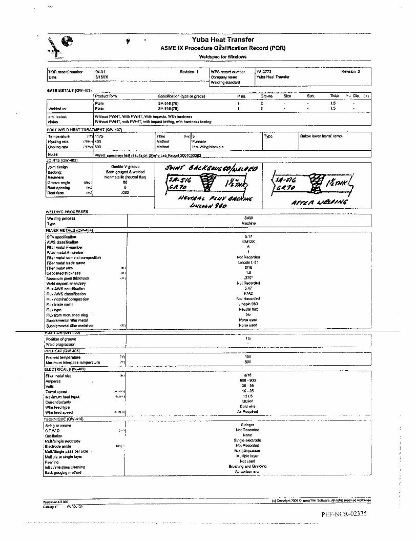
...
SFA spedlicalim AWS da68slficatlon FiYer metal F-number
I_-------
Yuba Heat Transfer ASME IX Procedure Qgalificatiort Record (PQR)
Weldspec for Wlndows
f *
5.17 EMIZK
6 I
SA-516 (70) 1 2 SA-516 (70) 1 2
Wiihout PWHT. With PWHT. Wllh Impads. Wlth hardness Without PWW. with PWHT, vhlh impact lesting. With hardness tesllng --
POST WELD HEAT TREATMENT (QW-407 Tempemhire I'P; 1175 Tkne !Ius1 5 T e e Below lower trans(. temp. HBatngfate I 'FhfI 400 MeVlod Fumace
N o l ~
Wlng rate 1 ' F W Mo Method lnwlaung blankets
PWHT so&.imen lest results on S h m Lab R e d 2001030363 ---
Preheat temperame VI Mau'mum hlerpass lemperalure ( "F l
Welding pmcesr I T m
I -.__-i 5Ml
150
SAW Machhe
Weld mebl A-number Filler metal nomhal cwnposilb Fder metal Wade name Filler metal lire Deposited thickness Maximum pas thldtness Weld de@ chemldry flux AWS spedflcation Rux AWS classlfhalion Flux nominal campositin flu^ lrade name flux type Flux from reaushed dag Suodemenlal fitler metal
1 Nol Recorded Lincoln L-6 1
3/16 I .5
,375' No1 Recorded
5.17 F7A2
Nol Recorded L w n 980 Neulral flux
N O None used
None used ! i i
- ...... . Supplemental finer metal vd. ... -_._-I _.-. . ---
I G
. . - " Weld pcogresslon
........ PREHEAT (aw-4061 -----.

' Type(Scale)
BHN
-..
.-.--__- SA416 (70) ' Dlstancefmmrudtxe SA416 (70) HA2
150.150.150 190. 185. 180 185. 165, 147
L- -~ ,
1 .................. . ....
.--_.----. Weldeh name ID Number
Jlm Dan's 3830 c((
. . -
I I I
S h w LabOratOlles-Mldftates Sherry Lab Reporl2001030359 PQR 04-01: Lab Req. 22-2001 Larry Pate
I .............
Laboratory test number Test Ne number Tests conducted by
-- Yuba Heat Transfer
ASME IX Procedure Qualification Record (PQR) - Test results (as welded) Weldspec for Windows _ _ ~ .--.- ~ -
I Revi-n 2
I WPS remrd number YA-3773 Company name Yuba Heat Transfer Wsldlne standard
PQRrecadnwnbec 0401 Date 3/15/06
~
,770 ,770 ,768 ,772
,742 .880 393 .703
0.5713 45000 78800 [Xlcue-Weld 1 0.5236 41300 78900 Dudle-Base Metal 0.5322 42000 78800 Dudile-Base Metal
Ductllegase W l 0.5427 43650 80400
- I,-& -1 1 [ W L , -.I
2 sets (topmOnOm) of reduced section tensbn l e u per QW-151.1 and QW-462.l(a) GUIOED BEND TESTS (aw.ifio) I Tvw of tesl I Acc8o(McaaiteIia I Result I Ca"ents 1
4 ITBnByBPse side bends , perQW-161.1 and OW462.2 . 1 Ow-163 1 Accaptable j m - A S M E I X - Q ~ ~ ~ . ~
--I.- ...-- ....... .-I-_.-.I_,._. Tests conducted on wedmens in the &welded corditJon: Shew Lab Reo"1030359.
TOUGHNESS TEI
number
..... Notch locakn N o t a type Spedmen size
0.394 x 0.394 0.394 x 0.394 0.394 x 0.394 0.394 x 0.394 0.394 x 0.394 0.394 x 0.394 0.394 x 0.394 0.394 xO.394 0.394 x 0.394
1 x W )
Test temperature ('F)
-20 -20 -20 20 .20 -20 -20 -20 -20
Impadvalues Drop wdght break
nla d a nla nla d a n/a n/a nla d a
(3, SlWarl
20 20 10 30 35 45 20 25 35
(ff a) 35 M 13 56 69 80 34 51 70
(hlilr)
31 33 14 43 57 80 34 46 63
Base Metal Bass Meld Ears Metal
HAt HAZ HAZ
Weld Metal Weld Metal Weld M&l
8 l g I
__-- Ihe As-welded mdltbn: Sheny Lab R< - I M0103035B.
Weldinq Enslnaei
Name
Donald L Undwrrocd
Dam 3 1 5/00

W R record w m k r Dale
04-01 R d k n 1 WPS record number YA-3773 Revfsion2 I 3/15/06 Campany name Yuba Heal Transfer -- i Wsldlna standard
Type (Scale) I Dlslanm from d a c e SA-516 (70) HAZ Weld HAZ
_.__-..-.-_--.-...._-.I. Weld& name ID Number . Stamp number Mechanical t e s t i i by
Jim Daws 3830 CK Laboratoly 1881 number Tesl Ne number Tests conducted by
~ . , ., Sherry Laboracories.Midstale.8 Sherry Lab Repon ZOO1030363 WR04-01; Lab Reg. 22-2001 Larry Pate ! .... . . . ,
Yuba Heat Transfer ASME IX Procedure Qual1ficatio.n Record (PQR) - Test results (PWHT)
Weldspec for Wndows
.757 ,756 ,751
1 -. 12 sets (loplbottm) 01 reduced d o n tensbn tests per a w - i 5 i . i and aW-462.l(a) _ _ - ~ . - - . k " n t s U D E D BEND TESTS (PW.160) --
Type of lest 1 Accepta;;;ria 1 Resun Comments I 4 vMSve(sa sMe bends psr PW-161.1 and QW462.2 Acceplable ~ - A S M E I X - O W - 4 5 1 . 1
hmMts OUGHNESS TESl
Speclmen numbec
1 2 3 4 5 6 7 8 0
--
- Nola location Notch lnx Spec!" &e (In.) I lh)
0.394 x 0.394 0.394 x 0.394 0.394 x 0.394 0.394 x 0.394
0.394 x 0.394 0.394 x 0.394 0.394 x 0.394 0.394 x 0.394
0.394 X 0.394
lmpeavalues , h p w e l g h t break NIA NIA NIA
136 77 , NIA 142 85 83 NIA
-I- - Test tempeatwe
( 'F )
-20 -20 -20 -20 -20 -20 -20 -20 -20
Base MeUl Easa Metal Base Metal
HA2 HA2 HAZ
Weld Metal Weld Metal Weld Metal
122 80 1 82 90 I 83
I 73 71 70 64
NIA NIA NIA NIA
!
\ i I
I
I lens: Shsrrv Lab Rewrt 2W1030363. I Tests cor cted on PWHT s ~ i
EHN 149.156. 149 I 140, 146,146 167,179,167
i
Welding Engineer
Name
Donald L. Uodemood
Date 7l1 vok
.. ~ - - - -- .... .... - . - - - .... - ~

Yuba Heat Transfer ASME IX Procedure Qualification Record (PQR) - Additional information
Weldspec for Windows
Dale WRrewrdnumber WPS remrd n u m k YA-3773
YlYo6 Canpany name Yuba Heat Transfer 04-01
Revislon2 1 Test conducted for additional FluxNvire combination using Lincoln L61 with Lincoln 960 Flux.
This revision: -correlates test results for as-welded and PWHT spedmens - corrects joint root opening (QW-402.10, nonessential variable) - adds that neutral flux was used as a non-metallic retainer (QW-402.11, nonessential variable) - adds that tiller metal nominal composition is not recorded [wire is A-I (QW-442) and wire classification is reported (QW404.5)] - adds that actual weld deposit chemistry is not recorded [wire is A-1 (QW-442), and wire classification is reported (QW-404.5)J - adds that flux nominal composition was not recorded (an alloy flux is not used for this test (C?\W-404..10)]. - corrects lowest amperage used during test welding (typographical error, should be 600 amps, not 400 amps)
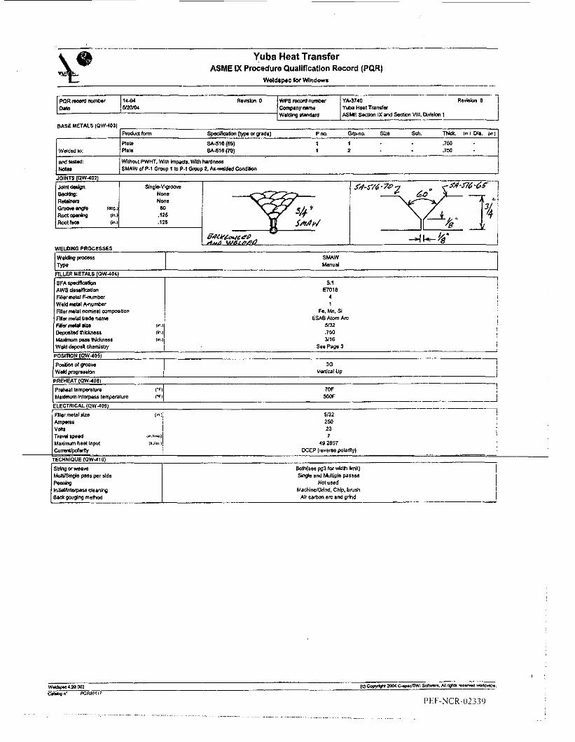
Yuba Heat Transfer ASME IX Procedure Qualification Record (PQR)
Wddcpec for Windows ___- .-
Rats SA-516 (65) 1 1 .7m - Welded (0: plate SA416 (70) 1 2 .7m
and tested:
J DCEP (reverre poknty)
TECHNIQUE (QW410)
Bolh(see pg3 for Wlh Ihlt) S b l e and Multiple passes
No1 used MachidGrind, Chip. brush
Air m+on a n and grind

W R d n u n b a 1444 Revisbn 0 WPS d n ~ b a Da(a SROXU Company n . 9 ~
Wddlng 8Bndard
YA-3740 Revision 0 Yuba Heal Trsder M E Sedlon IX a d Sedkn WI4. MMan 1
I : )
TENSILE TESTS (aw-i501 spa&nen number
A 8
W M Metal Weld Meld Weld Metal
P-1 or1 HAZ P-1 Grl W P-1 Grl HAZ P-1 Gfl HAZ P-1 GR HA2 P-1 GR w
R e d d s&km WMlh , / Thkknes kea UHImale low load ultimate unii strew Typs of blurs and - 0.748 0 750
(dn I (m I IN UbI (pa1 locpuon
0.699 i 0.5229 43wo 0 m Ovchieaars wai 0.701 1 . 0 . m 43100 0 m oUc(@Ba6e MeOl I
I I
-
i
1 O ” x 10” 10“ x lO” 10“ x IO” lO” Y lo” 1 O ” x 10” l h m x 10” 1 0 m x 1 0 ” lOmm x lo” 1 0 ” x 1 0 ”
camwnrs I Sherry Lab Repa( 2004050250
Tvpo d lesl k e p l ~ c e crileda ResulI Commenls GUIDED BEND TESTS (OW-160)
4 van- ride bends per OW-161 1 ond O W 4 6 2 2 ow-163 Acceptable we - ASME IX - QW-451 1
cormen$ TOUGHNESS TESTS (QW-170)
I .%my Lab Repar 2004050250
-32F -32F -32F -32F 42F -32F -32F -32F -32F
O l ~ t a n ~ e hom surf~ca SA-516 (65) w Wdd w Typo (S-W 200.200.210 195. 200. 200 205.205.216 i B it4 (Conwvfsdfrom Rockmill) Surface ’ 159,153.153 ’
i I
74 67 86 14 42 26 41 Bo 37
SA416 (70)
156,153,153
1% shaarl
50 45 55 25 35 30 35 45 35
50
59 22 30 22 30 42 29
4a NA NA NA NA NA NA NA NA N4
Welding Engineer 1 I Name Slgnalure
.. .._I_..1 - .- . ... . , ..... . .- . . ... .. . .. . . . ._.

-- - Yuba Heat Transfer
ASME IX Procedure Quallncatlon Record (PQR) -Additional information Weldspec for Windows
Sheny Lab Report 2004050250 Weld Deposit Chemistry Analysis (Weight %):
Carbon, 0.06 Manganese, 1 A8 Phosphorus, 0.008 Sulfur, 0.008 Silicon, 0.46 Copper, 0.07 Nickel. 0.03 Chromium, 0.03 Molybdenum, 0.01
Analysis conducted on weld surface by OE method.
Bead width when weaving was limited to a maximum of 3 X electrode diameter, both stn'nger beads and weave beads were used when welding the test plates.
Test plates welded on one side, joint was backgouged, and a single pass was placed on the backside

Y U B A H E A T T R A N S F E R P.O. Box 3158 Tulsa, Oklahoma
PROCEDURE QUALIFICATION RECORD No. 150-82 DATE 7-30-82 WELDING PROCEDURE SPEC. No. =DING P ~ o c ~ s ( ~ ) GTA Id. FCAW. SAW TYPES : W E METALS: Mate r i a l Spec. . 516 T y p e . ? x Grade- 79
FILLER METALS: Weld Analysis A No. 1 Electrode S i z e : l Fillet Metal F No. 6. 6. 6 SFA Spec. 5.18. 5.20. 5.17
PRMEAT: Preheat Temp. -150 En. , In t e rpass ~ m p 359%~. Mm. Others : POS-D HEAT TREATMENT: Temperature =me -S 1 OGher. =:Type mbco 2 cw Other , Composition 99.99% , Flow Rate 35 FLUX: Type H-800 (Hobart)
w 5 S A W W ELECTRICAL CHARACTERISTICS : Current DC , P o l a r i t y GTAhl-sp. FCA b p s . 100.170.500 b l t s 1 5 . 2 4 . 30 Travel Speed 2& iDaa7fDm. 1 6 i ~ m rECHNIQUE: String o r Weave Bead GTA\,r & SA W - Stri nz O s c i l l a t i o n NA f u l t i p a s s o r Single Pass Multipass
DDITIONAL INFORMATION:
YA-377 3
Semi-Automatic & Mach i n e \ l e u
P NO. I B r . 2 To P No. -1 Fr. 2 , Thk. 2" I R m g e a ~ 6 - 8 (' Dia. NA
Other s : # 0s-2 E71T-1 EMl2K U D h i l l 36 - Other SAW-1C POSITION: GTA[\'-3G. FCAW-3G Weld Progression
'* 1 FCAW t r a n s f et̂ mode : GlobUla@ 1 SuDp . f i l l e r - c k d powdered filler: None 1100°F.
-
. Other
, Other
S ing le o r Mult iple Electrode s w e Manual welding done in t h e 3G position t o satisfy OW409.1 f o r CVN . . *1 Max.Dass thk. 318" GTAW backina or tral-;AN;;q*qqT-u
IOINTS: Globular transfer
HK,AE,AB rock2k8! 9 9 9 0 , 526s t a p NO. -
4s t Conduct er Bob Hildebrandt
Groove Design Used
Hardness Test (EqUIVALDJT BHN 3000 KG LOAD)
I
We c e r t i f y t h a t t h e ~ t a t e m e n t s i n t h i s r eco rd are c o r r e c t and that t h e tes t welds were p repa red , welded a n d t e s t e d i n accordance with t h e requirements of Sect . 9 , ASME Code.
Signed Yuba Heat TransEer PEF-NCR-02'342
Ste 7\30
I \& h k--+ __ - - - -_ - - - _.. _. - ~ - - - - - _.
~ _.-- - - - -

P
3p e c imen No.
Y U . B A H E A T T R A N S F E R P.O. Box 3158 Tulsa, Oklahoma (918)234-6000
Ultimate Ultimate Character Total Load Unit S t r e s s O f Failure
Dia. Thick Area LB. PSI & Location
TYPES : MANUAL BASE METALS: Material Spec. SA-516-70 to SA - - 516 70 Type or Grade Normalized Fine P NO. 1 Gr.2 To P No. 1 Gr.2 , Thk. 1 I 1 , Range 5/8" - 8'' Dia. NA FILLER METALS: Weld Analysis A No. 1 Electrode Size: 1/8" 0
Others: AWS Class i f icat ion E7018-1 POSITION: 3G , Weld Progression V @ , - t i p R 1 - , j ?
Others : POSTWELD HEAT TREARIENT: Temperature S.R. fl 115OOF
F i l l e r Metal F No. 4 SFA Spec. 5 .1
Other PRMEAT: Preheat Temp. O F , Interpass Temp 500'F
No Dreheat maintenance after comDlation o f
I
I
Time 5 h r s . UP 266"F/hr. DOWN 731'Flhr. Other GAS: me NA , Composition NA , Flow Rate NA Other FLUX: Type NA Other ELECTRICAL CHARACTERISTICS: Current DC Amps. 120 bolts 26 Travel Speed '6 *
TECHNIQUE: S t r i n g o r Weave Bead Str ing Osci l la t ion mnp , Pola r i ty -E
, Other
L I . . - ~ $ - - ~ - @ : . - - I - n..,.. I,..% LI _ - - - - . -
NOT b Q U I # E D PER QW-401.3 This dOR ran t o
and bG-84 €or CVN'S. Ref. PQR 7&55
. satibfy S ipplemental Essential h r i a b l e s
t I
, Single o r Multiple Electrode sing1e :IUL L L ~ U ~ I J U L oru&;re r u a a nu I Ll pas s
ADDITIONAL INFORhLATION: Max. pass thk: 1/4" Max. J / i n aualified: 31.200
I I I
Location Type ergy f t / l b ) "F Foot Pounds 68.46.45
IMPACT TEST - CHARPY (UG - 84 SA - 370) Impact En- Tanp. Impact Values
E L D A 2 64 - 5 0 0
HAZ A 264 -50" 40,35,40
Har ness Test (EQUIVALENT BHN 3000 KG LOAD)
Location Hardness
JOINTS : m I 1 I 1 - 1 -r ~ -1
I I I I I I
G U I D E D B E N D T E S T S (QW- 160) Type And 1 I Type And I
f i g u r e N O . I Result I Figure No. 1 Result I 1 I 1 I I I . 1 t I I I
NOT REQUIRED( PER QW-401.3 I
I I I I I 1 1 1
I I I I
JeLder's Name J. Bennett Clock No. 1142 Stamp No. GP rest Conducted by: Met l ab Lab Test No. 037-89per Dan Zawson
We c e r t i f y t h a t t h e statements i n t h i s record a r e co r rec t and t h a t t h e test welds were prepared, welded and t e s t ed i n accordance w i t h the requiranents of Sect . 9 , ASME Code.
S i g n e d WBA HEAT TRANSFER D I V . 4 \
BY T- I b - PEF-NCR-02343
.- . . .... ..... . . , , . , .. . . . . .. . , ...... . ,._. .. . . . .. .... . . . . . .. . .. . . . ... .. .... . . ___.. . ,. .. ., , ,. ~

HANUFACTURE&S RECORD OF WELDING OPERATOR QUALIFICATION TESTS MACHINE WELDING (QW-361. 2
X C ) Welder Name Lonue, David {I3735 stamp No. Y
Using WPS No. Rev Date
VARIABLE USED FOR
QUALIFICATION QWALIPI~TI~N
RANGE
PROCESS
PROCESS TYPE
VISUAL CONTROL
AUTO ARC VOLTAGE CONTROL
JOINT TRACKING
POSZTION
.CONSUMABLE INSERT
BACKING
SAW
MACHINE
DIRECT
NfA
MNUAL
1G
NONE
WELD METAL OR FLUX
MACHINE
DIRECT
NfA
MAWAL OT AUTOMA TIC
1G
w r m OR wrmouT
WITH BACKING ONLY
GUIDED BEND TEST RESULTS QW-462.2(a), QW-462*3(~), QW-462-3(b)
TYPE AND FIG. NO. RESULT / . :
: : : f
. t : : : 2 . . : . . t . 8 : t
RADIOGRAPHIC TEST RESULTS (QW-305) (For alternative qualification of groove welds by radiography)
RADIOGRAPHIC RESULTS SATISFACTORY PER A W N CASH / LEVEL 111
TEST CONDUCTED BY W BA HEAT / Tim Morris LAB. TEST NO. N/A
We certify that t h e statements in this record are correct and that the test welds were prepared, welded and tested in accordance w i t h the requirements of Section IX of the ASME Code.
Organization YUBA HEAT TRANSFER DIV.
BY
PEF-NCR-02344
. . . .. . . . -. ._ . . . . . ... .. - .. . - . . ... . ..... . .- .. . . . .

Yuba Heat Transfer ASME IX Welding Procedure Specification (WPS)
-. As-welded
Mn. Mal SFA Classification F-no. A m . Chemlcal analysis or Trade name
-- No min. 1.5 6 1 Any E70T-1 OT E71T-1 wire --_I-
...
_I__.-.-- . L.,. Weldspec for Wlndows .- __--_ -- --[- Revision 27 Qualified to Eic$;;i;f;nd Section VIII. Division 1 1
-+ 3/16/06 Company name I
...... ...... -...-.._ -_-...,, _ _ _ , . ~ . . . ~ Supporting POR(s) 035-89; 03649; 24-92; 43-98; 65-96
- Section IX wllh Latest Mandatory Addenda --I--_.. ".I-. . . . . . . . . . . . . - ~" -
FCAW P-1 Materlals, As-Welded or with PWHT Groove, fillet, no PWHT (As-welded), wllh PWHT i
With PWHT Mh Mar. I NoGq---. --8--\
I Joint details for this welding procedure specification in:
--.._ ;70T-l orE7lT-1
- - Sup. 6iIer
I I Production drawings. Engineering spedfications
-.- .............. __ . None -
-I-.
-I-.- --- I ...... BASE METALS (aw-403)
Carbon sheel (P l ) Pno. 1 Carbon steel (Pl) Pno. 1
Welding process
T W Preheat temperature 1.
Maximum inlerpass lemperalure i"
Filler metal size (1'
Layer number Position of groove Weld progression CumnUpdarity Amperes Volts Travel speed (<" :<,(I
Wire feed speed iw :n,r
Maximum heat Input (W:h
Arc transfer mode Shielding: Gas type
Trailing: Gas type
Backing: Gas type
Strlng or weave Orifice/gas cup size C.T.W.D (111
MultilSingle pass per side Maximum pass thickness (I"
Weld deposit chemistry Notes
Flow rale 1 0
flow rate (Cll
Flow rale :c11
--
1 Backing: I Backgouged & welded P-no. 1
Inone See Pages 2 and 3
- ..-..-.-- I
THICKNESS RANGE QUALIFIED AS-WeldEd With PWHT
0.188 Impact lesled Parllal pen. Fillet welds
DIAMETER RANGE QUALIFIED ,,>. ', 1 As-welded I M y h P W H T j Min. Usl. Ma*.
------, _- FCAW
Semi-automatic See page 2 for preheat !
5OOF I
,045. 1116 j All All
Vertical up (when applicable) DCEP (reverse polarity) 8
I See Page 3 I
I I
See Page 3 I
Sea Page 3 AdJust for ampdvoltdcondiUons
Not limlted
Globular I
35 to 50 c 0 2 I
None ,
None
Stringer or Weave 5/8 (.as): 518or 3/4 (1116)
Singb or Muiliple passes Less than 112
A-1 per QW-442 See Pages 2 and 3
518-314 (.045); 344-1 (1116)
- . - .-
pEF-NCR-02345 . . . . . . . . . . . . . . . . ._ . . . . . . . . . . . . . . . . . . . . . .
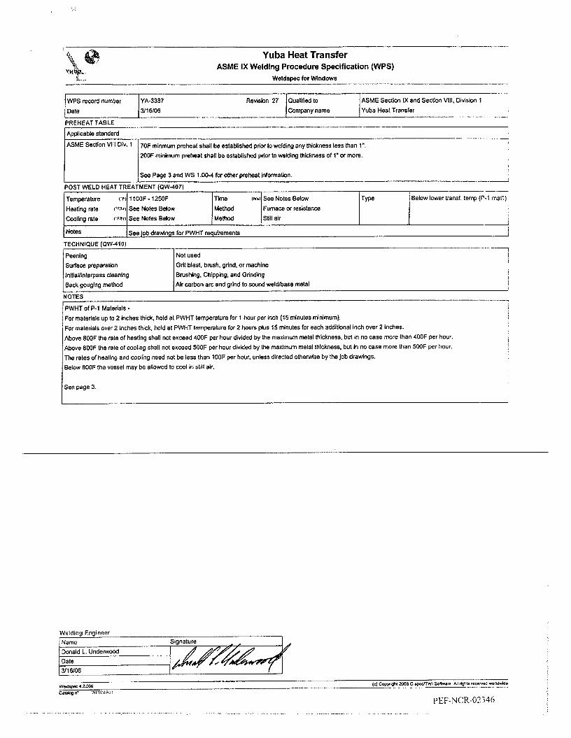
Q, Yuba Heat Transfer & %$
Y".@pSlr, 9- ,-
ASME IX Welding Procedure Specification (WPS) Weidspec for Wndows . - I_-_--. . - - - - ---
Temperature ( 'F) 11OOF - 12WF T h e lnrd See Notes Below
ASME Sedion IX and Section VIII, Divislon I
- ._. __- ~ .___..^_ --_ --- PREHEAT TABLE
Below lower transf. temp (P-1 marl) ,
_. _. __ . . . - ApplicaMe standard
ASME SedlOn t--/------ 2OOF minimum preheat shall be established prior to welding t h m s s of 1' or more
Div. 1 70F minmum preheat shall be estaMished prior lo welding any thickness less than 1".
Heating rate I ' F W
W l l n g fate ('Fmrl
Notes
See Notes Below 1 ;;;; I ;;me or resistance See Notes Below
See job drawings for PWHT requirements -
i
For materials up to 2 inches thick, hold al PWHT temperature for 1 hour per inch (15 minutes minimum). For materials over 2 inches thick. hold at PWHT temperature for 2 hours plus 15 minutes for each additional inch over 2 Inches. Above 800F the rate of heating shall not exceed 400F per hour divided by the maximum metal thickness. but in no case more than 400F per hour. Above 8WF the rate of cooling shall not exceed %OF per hour divided by the maximum metal thickness, but in no case more than 5WF per hour. The rales of heating and cooling need not be less than 1OOF per hour, unless directed otherwise by the Job drawings. Below 800F the vessel may be allowed to cool in still air.
See page 3.
Welding Engineer Name Signature Donald L. Underwood Dale 3/16/06 -
. .. . . . . - . .. . . ..... . " . .. ... . . . .. ,

r"""'-, Revision 27
.. ._
All weld joints shall have a minimum of two passes.
Each weld shall be stamped with the welder's unique identification stamp adjacent to the weld at intervals of 3 feet or less, whenever the material thickness is 1/4" or more.
FCAW AmpNoltWlre Feed Ranges:
For .045 dlameter wire - 140 to 280 amps 24 to 31 volts 180 to 520 inches per minute wire feed speed
For 1/16 diameter wire - 200 to 350 amps 25 to 33 volts 120 to 350 inches per minute wire feed speed
I-" _ _ ! S- Yuba Heat Transfer i
ASME Section IX and SectjOn VIII, Division I Qualified to Company name
~ _ _ _ .

4 .
Y U B A H E A T T R A N S F E R I-
P.O. Box 3158 Tulsa, Oklahoma (918) 234-6000 :,
PROCEDURE QUALIFICATION RECORD NO. 035-89 DATE 3-22-89 WELDING PROCEDURE SPEC. NO. *
WELDING PROCESS(ES) YA-3779
FLUX CORED ARC v ( E C A W \
Spec h e n No. 1 2
TYPES : W E METALS: Material Spec. SA-516-70 t o SA-516-70 TYFe Or m a d e Normalized- f i n q P No. 1 GR.2 To P No. 1 GR.2 , Thk. l / 2 " *1, Range 3/8" - 3/4'Dia. NA FILLER METALS: Weld Analysis A No. m - 1
s EMMUTOMAT I C
Electrode Size: .045" d
WIDTH . Total Load Unit S t r e s s O f Failure $j!$. Thick Area LB. PSI h Location
.757 ,485 ,3671 26.890 73.250
.753 1 .485 3652 26.920 73.713
F i l l e r Metal F No. 6 SFA Spec. 5.20 Other6 : AWS Classif icat ion: E71T-1 Kobe wire Kobelco F r w c - 7 1 1 POS ITION : 3G , Weld Progression Vertical- up Other PREHEAT: Preheat Temp. 70°F , Interpass Temp 500'F Others: No preheat maintenance a f t e r completion of weldment. POSTWELD HEAT TREADlENT: Temperature Time 5 hrs . Up 400°F/hr Down SOO"F/hr . Other = : T y p e CO, , Composition 99.995% , Flow Rate 30 CM Other FLUX: Type NA
S . R . @ 1150'F
L o the r , Pola r i ty RP
, Other ELECTRICAL CHARACTERISTICS: Current DC
TECHNIQUE: S t r i n g o r Weave Bead 1/2" max. weave Osc i l l a t ion None Mul t ipas s or Single Pass Mul t ipass
Travel Speed '5 Amps. 140 Volts 21
, Single or Multiple Electrode Single
Location *1 Weld *1 HAZ
ADDITIONAL INFOR~ATION: Max. bead thk: 1/4" ox supplementary powdered f i l l e r : None Globular t r ans fe r T ra i l i ng gas: None
Max. J / i n qual i f ied: 35 ,280- Supplemental
Contact s t i c k o u t : 3/4"
Type ergy f t / l b ) * F I Foot Pounds
A 2 64 -25' 104.10 1 113 A 26b -25' 58, 58, 77
I
T E N S I L E T E S T (QW-150) 1 I I I Ultimate 1 Ultimate ICharacter I
t I I I I I I I I I I I I I I 1 1
IMPACT TEST - CHARPY ( U G - 84 SA - 370) I I Impact ~ n - 1 ~ m p . I Impact Values t I I I I I 1 t 1
--u-aN- 4 4 %
on 3/8" thk. plate p e r paramet used on LIZ" p l a t e W P S q u a l i f i
Groove Design Used
Hardness Test (EQUIVALENT BHN 3000 KG LOAD)
Location Hardness
Weld - 207 187 187 143 149 163 128 131 13
Welder's Name J . Bennett Clock NO. 1142 Stamp N O . GP T e s t Conducted by: Metlab Lab Test No.035-89 per Dan Lawson
We c e r t i f y t h a t the statements i n t h i s record are c:rrect and t h a t t h e t e s t welds were prepared, welded a n d tes ted i n accordance with the requirements of Sect. 9, ASME Code.
45-LIY
3 - 2 2 - a i Date
Signed YUBA HEAT TRANSFER D I V .
BY
I PEF-NCR-02348
S
t

-.:
3. 4. Y U B A H E A T T R A N S F E R 'P.O. Box 3158 Tulsa, Oklahoma (918) 234-6000,
PROCEDURE QUALIFICATION RECORD No. -036-89 DATE 3-23-89
WELDING PROCESS(ES) TYPES : SEMIAUTOMATIC W E METALS: Material Spec. SA-516-70 t o s A- 516-70 TYPe Or Grade Normalized-fine P No. 1 GR.2 To p NO. 1 GR.2 , Thk. 1%" , Range S/8ff-81t Dia. NA FILLER METALS: Weld Analysis A No. E71T-1 Electrode Size: ,045" 0 F i l l e r Metal F No, 6 SFA Spec. 5.20 o t he r s :
Other ---- POSITION: 3G , Weld Progression Vertical-up PREHEAT: Preheat Temp. 200 " F , Interpass Temp 500 " E' Others: No preheat maintenance a f t e r completion of weldment, POSTWELD HEAT TREATMENT: Temperature S.R.@ 1150°F Time 5 h r s . Up 100°F/hr Down 100°F/hr. . Other GAS: Type co, , Composition 99.995% , Flow Rate 30 CFH Other FJXX: Type NA ELECTRICAL CHARACTERISTICS: Current DC , P o l a r i t y RP Amps. 140 b o l t s 21 Travel Speed 5 IPM , Other TECHNIQUE: S t r i n g or Weave Bead 1 /2" Ma a e . O s c i l l a t i o n -e Multipass o r Single Pass Multioass
ADDITIONAL INFORUTION: Max, bead thk. 1 /4 I f Max. J / W a u a l i f i e d : 35 ,780
WELDING PROCEDURE SPEC. NO. YA- 3779 FLUX COR.ED ARC WELDING (FUN)
AWS C l a s s i f i c a t i o n E7. T-1 Kobe wire Kob&o Frqntiarc -711
L Ocher
, Single o r Multiple Electrode Single
a S Trai l ing gas: None Contact s t ickout :
Welder's Name Clock No. 1142 Stamp No. GP J . Bennett Test Conducted by: m a b Lab Test No.
We c e r t i f y that the statements i n t h i s record a r e correct and t h a t t h e test welds were prepared, welded and t e s t e d i n accordance with the requirements of Sect. 9 , ASME Code.
Dan Lawson wper :
Signed WEA HEAT TRANSFER D I V .
3-22- 8c( BY 7-iiZvn.A

Y U B A H E A T T R A N S F E R P.0. Box 3158 Tulsa, Oklahoma (918) 234-6000
PROCEDURE QUALIFICATION RECORD No. 24-92 DATE - - WELDING PROCEDURE SPEC. No. 3889 WELDING PROCESS (E) FL-G TYPES: SEMLAUTOMTIC BASE METALS: Material Spec. SA-516-70 t o SA-516-70 Type o r Grade N- P No. 1 Gr.2 To P No. 1 Gr.2 , Thk. 1%" - 3/8" , Range *l Ma. N/A
Fi l le r Metal F No. 6 SFA Spec. SFA- 5 1 20 Others : AWS C l a s s i f i c a t i o n : E71T-1 (Kobe wire) POSITION: 1~ , Weld Progression N/A Other PREHEAT: Prehea t Temp. 200'F min. , In t e rpass Temp 500'F msx. Others : POSTtJELD HEAT TREA'IMENT: Temperature AS WELDED CONDITION Time N/A Other GAS: Type co, , Composition 100% , Flow Rate 35 CFH Other FLUX: Type N/A ELECTRICAL CHARACTERISTICS 1 Current DC , P o l a r i t y Reverse Amps. 190 b o l t s 26 Trave l Speed 10 iom , Other TECHNIQUE: S t r i n g o r Weave Bead S tr ing O s c i l l a t i o n cZultipass Or Pass-, S ing le o r Mul t ip l e Elec t rode S ing le 4DDITIONAL INFORWTION: ki Th-Lck member range. 5/8" - unl imi ted thk . Thin member: 3/8 11 - 311 >er QW-202.4(2) Deposited weld metal range: 3/4" mx.. J / i n . q u a l i f i e d : 37.050 Max. pass t h k
T O ~ N T S : Supplemetal f i l l e r : Nom
FILLER METALS : Weld Analysis A No. 1 Electrode Size: 04511 0
d. Other
none
3/16" Tubular wire, Globular t r a n s f e r . T E N S I L E T E S T (QW-150)
Ul t imate Ultimate Character To ta l Load Unit S t r e s s Of F a i l u r e
No. p j b . Thick Area LB. PS I & Location
2 ,750 .353 ,264 20$k 79,000 3 /8"base-du
W IDT: 1 Specimen
1 774 - 3 5 8 -766 21 ~ nn 79,000 3/8"base-du(:t
I I I I I I I
1 I I I I t
Locat ion I Type e rgy f t / l b ) OF- Foot Pounds Weld / A 240 -25'F 42,52,48
3/8" HAZ I A 240 -25"F 110.107.102 lg'l HAZ / A 240 -25'F 76.54.44
I I 1 I
i I I I I
T r a i l i n g g a s : None
le le m
-~ Groove Design Used
Hardness Tes t (EQUIVALENT BHN 3000 KG LOAD)
Locat ion I Hardness
Weld - 172 165 195 167 205 222
ZLder's Name D. Schwei tzer Clock No. 3470 Stamp No. BW s s t Conducted by: Mids ta tes Lab Test No. 24-92 p e r B i l l Vesely
We c e r t i f y t h a t t h e s t a t emen t s i n this record a r e c o r r e c t and t h a t t h e t e s t welds were prepared , welded and t e s t e d i n accordance wi th the requirements of S e c t . 9 , ASME Code.
Signed YUBA HEAT TWSE'ER D I V .
Date /a23092 &A nn&

b
I YUBA HEAT TRANSFER OfVlSmN cn ~ X ~ I ~ . W T V L U ~ ( I L * M O U A ? ~ ~ O ~ .@u)w-Tu(Qm PROCEDVRE QUALIFICATION RECORD No. 4?-% DATE H9-96 I
WELDIKC PROCEDURE SPEC. No. YA- 4072 WELDING PROCESS (ES) FCAW TYPES : Semi-automat f c BASE METALS: Mate r i a l Spec. SA-516-70 Norm to S A - 5 1 6 - 7 0 OE T TYPe C;r.deNorm. to Q&T P No. I ~ r . 7 TO P NO. 1 Gr.2 Thk. 318" Range 3/8" min, Dlo. N/A FILLER H L ? h t S : Weld Analys is A No. . E - 7 1 T - 1 Electrode Size: .04!?' .0 F i l l e r Metal F No. 6 o t h e r r : AWS Classlficatlon: E71T-1 bbe1tco F r o n t m - 7 1 1 p a l v POSITX": 3G * Weld Progression Ver m e r PRMEAT: R e h e a t fmp. 70 dea.F m l n . *p 500 deq.F max. Others: Sumlemental filler or nn w k r e d filler: m e PDSl%'ELD H U T TRUiMDX: Temperature A s Welded Condition Tfme- N/A Other CAS: Type c02 , Cumposition Inn2 , Flow Rate ?n CFH Other
N/A Q t h e r ELECTRICAL CHARACTERISTICS: Current , P o l a r i t y RP FLUX: Type
c.nps. 140 Vol t s 2 1 T r ! 5 IPM r~cHh'lQ:~: S t r i n g or Weave Bead Weave l u l t i p a S S or S i n g l e Pass Multipass i D D l f l O N W , IhTORvATIOh': Max. J/in. qualified: 35.280, Globular transfer, Trall inq oas: None
SFA Spec. 5.20 Fl ux-cored wi r e
c
'
, Other Os c i 1 fr tion-
, S i n g l e or Mul t ip l e Elec t rode Slnqle
Hax. pass thk.: 1/4"
I E h' S I L E 'I E S T (QV-150) U 1 t imet r Ul t ime t e Character
;p e c i m en Tota l Load Unit Stress Of Fa i lu re No. D i a . Thick A r e a LB. PSI 6 Location
I
OJFPS :
Croove Design Used
Elder 's Hune D . Clock No. 3420 Stomp No. EO . s t Conducted by: Sherry Lab. Lab Tes t No. 43-96 per Dan Lawson
&!e c e r t i f y t h a t t h e b t r t a ~ e n t ~ in t h i s record 4 t e c o r r e c t a n d t h a t t h e t e s t welds were p r e p a r e d , ve lded a n d t e s t e d in accordance u i th t he r e q u i r m e n t s of S e c t . 9 , ASKE Code.
Hardness Tes t (EQUJVALEKT B% 3000 KG LOAD)
Lac 8 t i on Hardness
: t e 3-14-96 S i g n e k YUBA HEAT ,TRANSFER DIV. BY 1 . L w

- --- . - - YUBA HEAT TRANSFER DIVISTT)N
CD ~ X I l u l - T U L 4 r , ~ O M ~ 7 4 l O l - ( P l ~ ~ - . f U ( F PROCEDVRE QUALIFICATION RECORD No. 65-96 DATE 3-1 9-96 WELDING PROCEDURE SPEC. No. YA-4072 ELDING PROCESS(E3) FCAW TYPES: - ic EASE METALS: Mate r i a l Spec. -51 6-70 Type er made SA-516-70 to SA P No. 1 To P No. 1 , Thk. 3 /4 " , Range 3/16"Elj" Dla.
F i l l e r Metal F No. 6 SFA Spec. 5.20 Otherr : - AWS Classification: E71T-1 Kobe1 i co Front jarc / I I POS ITICK : 1G , Weld Progression N/A Orher PREHEAT: Prehea t Temp. 70 dao.F min. , I n t e r p a s s Temp 500 degS_max. O t h e r s : POSTWELD HEAT TRLAMEKT: Temperature Time N/A Other CAS: 30 CFH Other Type c02 , Composition Flm Rate FLUX: Type N/A O t h e r ELECfRlCAL CHARACTERISTICS: Current DC , P o l a r i t y RP Amps. 140 TECHNIQUE: S t r i n g o r Weave Bead Strinq O s c i l l a t i o n None Mult ipass o r S i n g l e P a s s Multipass ADDITIONAL fhTORYATlON: Max. bead thk . : 1/4" SuDDlemental f i l ler pr D owdered f i 1 ler metal :
FILLER HIJTALS: Weld Ana lys i s A No. E7lT-1 Electrode S i t e : .o 5'' 0
No Dreheat maintenance aftcr-&;nn nf w p l h t As We1rl1-d C d i t i n n . .
bolts 71 Travel Speed Manua 1 , Other
, Sing le or Mul t ip l e E lec t rode Sinale
. . None Globular t r a n s f e r T r a i 1 t n g - g a s A h c
JOINTS: T E K S f L E T E S T (QW-150)
U1 t ime r e Chsracter L'nit S t r e s s Of F a i l u r e
I I I I 1 I 1
IMPACT TEST - wRp\i (UC - 84 SA - 370) 1 I Impact m- 1 T ~ P . 1 Impact va lues
~ o c e t i o n I Typelergy f t / l b ] I *F- I Foot Pounds 1 1 I I I
e o o v e Design Used
Hardness Tes t (EQUIVALENT BHh' 3000 KG LOAD)
LOC8tl Dn Hardness
I
e l d e r ' s Name J . ' w a n Clock No. 3 1 7 0 Stamp No. C N e s t Conducted by: Sherry La bs. Lab Tes t No. 65-96 per Dan Lawson
We c e r t i f y t h a t t h e s t a t a n e n t 6 i n t h i s record 4re c o r r e c t a n d t h a t the t e s t v e l d s were prepa red , welded a n d tested l a accordance v l t h the r equ i r emen t s of Sec t . 9 , U H f . Code.
Signed YUBA HEAT TRANSFER D I V .
BY
I

QW-484 SUGGESTED FORMAT FOR MANUFACTURER'S RECORD OF WELDER OR WELDING OPERATOR STApCp cmluG60 f%?#M
Gat0 zp , WLR603 QUAL1 FICATION TESTS
ON 44-@ (See OW-301, Section IX, ASME Bo i le r Pressure Vessel Code)
Welder Name D LOGUE Check No. 3735 Stamp No. LZQ Using WPS No. YA-3387
the above welder is qua l i f i ed f o r the fo l lou ing ranges
Record Actual Values Var iable Used in Qua l i f i ca t i on
Process FCAW Process Type SEI41 Backing(meta1, weld metal, flux, etc.(QW-402)) WELD METAL
Ih i c kness Ma te r ia l Spec. (PW-403) PI t o P1
Groove -864 F i l l e t N/A
Groove 6.000 F i L l e t N/A
Spec. No. ,SFA 5.20 Class E71T-I F-NO. 6
D i ameter
Fi l l er Metal (PW-404)
Pos i t i on (QU-405) 6C Weld Progression (QU-410) VERTICAL UP
E l ec tr i ca L Character i s t i c s (PU-409) Cas Type (QW-408) c02
Current DC P o l a r i t y RP
Qual i f i c a t i o n Cments :
Qua l i f i ca t i on Range FCAW GMAW SEMI BACKiNC ONLY Pl-PI1 t o P1-PI1
MAX TO BE WELDED MAX TO BE WELDED
> or = 2.875 ALL DIAMETERS
SFA 5.9, 5.18, 5.20, 5.22, 5.28 Per SFA l i s t e d above
ALL VERTICAL UP
DC RP SP
Guided Bend Test Results aw-462.2(a), QU-462.3(a), QW-462.3(b) Type and Fig no. Result
VISUAL EXAM PER OW-302.4 SATISFACTORY
Radiographic Test Results (PU-304 & PU-305) For a l te rna t ive qua l i f i ca t i on o f groove welds by radiography
Radiographic Results: SATISFACTORY PER ALLEN CASH LEVEL I I I
Test Conducted by YHTD Laboratory - Test No. N/A We c e r t i f y that the statements in t h i s record are correct and tha t the tes t welds were prepared, welded and tes ted i n accordance with the requirements o f Sections I X of the ASHE Code.
Organization YUBA HEAT TRANSFER
Date 03/01/95
(Deta i l of record o f t es ts are i l l u s t r a t i v e only and may be modified t o conform t o the type and number o f t e s t required by the Code) NOTE: Any essential var iables i n addi t ion t o those above sha l l be recorded.

-.--__ Yuba - Ecolaire
2121 North Wlst &&Avenue, Tulsa, Oklahoma 74116 ASME IX Welding Procedure Specification WPS)
Weldsoec for Wlndows
Manium (P51) P-no. 51 Grp-no. I Type
WPS record number YA-3867 I Date 1514106
&-welded With PWHr
Revislon C Quallfledto Company nanw
Mh. MBX.
ASME Section IX Yuba - Emlaire
LR. Llu.
Supporting PaR(s) Latest Mandatoly Addenda -- -c -_I- - _. .- . -_
Base mew or weld metal P-no. 51 G W O . -
GTAW of P-51 materials Gmve. fillet, no PWHT IAs-weMedl
Complete pen. 0.063 2.75
Jolnt Joint details for this welding procedure specification In: I Produdion drawings, Engineering spedRcatlons
Retaineo See pages 2 and 3; See 4 and 5 for tube welding
Impact tested Parlial pen. 1 1 0.063 1 2.;5 1 1 : 1 Flllet welds no min. 2.75
w a d to Eaddng:
Aswelded with PWHT Mh. Max. M h Mar
Nom. pipeltube s ~ e - ~ o min. no max. -
SFA As-Mded With PWHT * wax. wn. Mar
Classifcallon F-no. A-no. Chemlcal analysls or Trade name
Cons. insert I Flux
5.16 GTAW
I: I: see page3 51 NA Unlbraze or equal (see page 3)
-.-
1: I: I: Welding process
T W Preheat temperature ('Fl
Maximum Interpass temperature I'FI
Tungsten size (In I
Filler metal &e fn 1
Layer number
. Tungsten type
- None - - None -
-- GTAW Manual
50F 250F
1116.3/32, or 110
1116 or 3/32 All
SFA5.12 M h - 2
Notes
Position of groove WeM progression CurrenUpo!arity Amperes volts Travel speed
- See pages 2 and 3
(I" lmol
All Vertical up when applicable
OCEN (straight polarily) 130 max. 19 max.
4 minimum I Maximum heat input IkJAi! I1 37.05 DC pulslng current Shielding: Gas type
FIOW rate Trailing: Gas lype
Flow rate
Backing: Gas type flow rate
String or weave Orificelgas cup size MuftllSingle pass per slde Weld deposit chemistry
None Argon, Welding Grade (SG-A)
30 to 35 None required (Argon if used)
20 to 30 (if used) Argon, Welding Grade (SG-A)
20, (see page 3) Slringer or Weave
12 or larger Single or Multiple passes
Per SFA-5.16
PEF-NCR-023 54

Yuba - Ecolaire 2121 North 161st East Avenue, Tulsa, Oklahoma 74116
ASME IX Welding Procedure Specification (WPS) Weldspec for Windows -
Revision C 1 PuaiMed to ASME Section IX Company name Yuba - Ecolaire
_ _ _ _ _ . _ " _ . _ " . _ _ I ~ - .._. -.- ..
ASME &ion IX
Surface preparation I IniIiaVinlerpass deaning
~
5OF preheat. do no1 preheat to over lOOF prior to welding. Allow weld la cool la below 250F prior to placing nex3 weld bead. The weld and base melal musl be kept awed (blanketed) with Mgon inerl gas shielding at all times whlle above 8OOF to prevent contamlnatlon by the atmosphere.
Grind or machine, and dean With approved solvent prior to welding I Brush andor Grind-Use only dean slalnless steel wire brushes
Closed or outofchamber Peenlng
I None .-.- - Back gouging method
NOTES
Outofchamber No1 used !
Weld and base melal must be kept wvered with Argon inerl gas shlaldlng unlll betow 8OOF to prevent contamination by the atmosphere.
Use additional fixtures or tralllng shields lo eslabllsh and malnlaln Argon shielding on weld and base metal to prevent contamlnation.
Acceptable weld and base metal cdorations are bright silver to llght straw yellow.
Weld or heat affected zone colors of dark yellow, Mue, grey, oi whlte lndlcale contaminalion and are not acceptable.
See Page 3 for more notes. Also see pages 4 and 5 for tube-lo-tubesheet welding.
Welding Engineer
Name Donald L. Underwood Date 5/4/06
PEF-NCR-02355

WPS record number Date
When making fillet or other attachment welds on titanium materials that are less than 1/4“ thick, a gas purge on the backside is required
For tube-to-tubesheet welding, see pages 4 and 5.
1 YA-3887 Revision C Qualifiedlo ASME Section IX 5/4/08 Company name Yuba - Ecolaire
--I---
PEF-NCR-02356

Yuba Heat Transfer Division Division of Conndl Limited Partnership
P.O. Box 3 158, Tulsa, Oklahoma 74 10 1
WPS Number YA-3887 Rev. C Date: 5-4-06 Supporting PQR: 108-86; 05-92; 12-04 Page 4
Welding Process (QW-250): GTA W Manual
Base Metafs (QW-403): P-Number/Group Number P-5 1 Clad tubesheet to P-NumbedGroup Number P-5 1 Tube Ligament (min) Per Design drawing Tubesheet Thickness I - 1/4" or greater Thickness Range (tube) .024" to .028"
Position (QW-405) Positions Tube horizontal and
Progression Vertical up or down Tubesheet vertical
PWHT (QW-407) Holding Temperature Range Max. Hold Time
None required; As-welded None required; As-welded
-
Electrical Char. (QW-409): Max. Heat Input Polarity DC straighr polarity
Amperage 75- I 10 amps Pulsing Lurrent Not used Electrode Size
rravel Speed Manual
Voltage 14-19 volts
3/32" or 118" dia. Electrode Type EWTh-2
Joinb (QW-402): Groove Design QW402.1 Backing P-5 I tubesheet Root Spacing Roll to contact Retainers None used Tube Diameter 1.04" to 0.85" Tube Wall Thickness
See page 5
0.024" to 0.028"
Filler Metals (QW-404): SFA Number Filler Size F-Number A-Number AWS Classification Addition or Deletion of Filler Preplaced Metal Insert Filler Metal Product Form Max. Weld Metal Thickness
SFA-5.16 when needed 1/16" when needed
None assigned ERTi-2 (see page 3) Yes and no None used Bare solid wire (when used) 1.390" maximum
F-5 1
Preheat (QW-406) Preheat (min) 50 F minimum Interpass (max) 200 F maximum Preheat Maintenance None required
Gas (QW-408) Comp. & Flow Shielding, Backing, Trail Gas Argon, welding grade
Flow rate: 25 to 35 CFH
Technique (QW-410) String or Weave Bead Cup or Nozzle Size Oscillation Multiple or Single Pass per Side Sngie or M u l t @ l H ! i ~ ~ Closed to Out Chamber Electrode Spacing Manual or Automatic Method of Cleaning Method of Backgouging Peening
String or slight weave I 2 or larger None used Single pass
le Out of chamber Not applicable Manual See Below Not required Not permitted
Votes: durfaces to be welded shall be steam andor solvent cleaned and protected from contamination. Approved solvents are acetone or isopropyl alcohol. All tube holes and tube ends shall be solvent cleaned prior to pushing. Tubes may be expanded prior to welding. If tubes are expanded, the tubesheet face and all tube ends shall be thoroughly cleaned and protected from contamination prior to tube welding. The weld area shall be protected from contamination during the entire welding operation. Base metal to be welded shall not be touched with bare hands after final cleaning. If accidentally touched, clean the surface again as directed above. Clean white cotton gloves should be worn while welding. Clean, stainless steel wire brushes may be used for surface cleaning in addition to solvent cleaning. Do not touch filler metal with bare hands or fingers. Clean all filler metal prior to use with an approved solvent. If filler is used, clip the contaminated end from the wire each time it is withdrawn prior to depositing additional filler in weld. Maintain argon shielding gas flow on the weld until it has cooled sufficiently to prevent contamination in air (cooled well below 800F). Weld color shall be bright silver. Contact Welding Engineer or Weld Technician if weld is discolored.
Wellding Engineer,.YHTD - Date

Yuba Heat Transfer Division Division of Connell Limited Partnership
P.O. Box 3158, Tulsa, Oklahoma 74101
WPS Number YA-3887 Rev. C Date: 5/4/06 PQR: 108-86: 05-92: 12-04 Page 5
High frequency arc initiation required. Use foot pedal with arc decay to terminate arc.
Terminate the arc on the weld and hold gas coverage (trailing shield) until the weld has cooled sufficiently below 800 degrees F to avoid discoloration (contamination).
Seal welds are to be made as single pass autogenous (no filler added) welds. However,tiller may be used b y e welder w h i G i l W I ’ C f p i d i i ~ ( o r osner defects) seen whiie welding, or as needed for repairs. When the weld requires the addition of filler metal, it should be added continuously without intermittent dipping wire in and out of the weld. Filler metal removed from the gas shielding will be contaminated, and shall be cut back at least 1/2” to remove and discard the contaminated wire end. before the remainder of the wire can be used in the weld.
__
Finished weld color should be bright silver- Contact the Welding Engineer or Weld Technician if weld is discolored for directions concerning cleaning or repair.
Welding Engineer, YHTD ’ Date
P EF-NCR-023 5 8

..... ....... ._ . - .... _. . . . . . . . . . . . . . . . . . . I ____- .~~ - _. - __ . _-_ . . , , , . ._
Yuba Heat Transfer P.O. Box 3158, Tulsa, Oklahoma 74101
ASME IX Procedure Qualification Record (PQR) Weldspec for Wlndows .__._____.______--__-. .. . ... -.-
7 -- .-- WELDING PROCESSES __.-
Weldlng pcocsss
T W
FILLER METALS (QW4041
SFA .pedfiuruOn AWS daSsMcaUofl Filler mehl F-number Weld meld A-number Filkr Mtal nomhal mmposiliw fllkr wld bade nsm Filler nmld size Deposited (hlCkneS8
Maximum pass hkknesr Weld deposil chemirtv
POSITION (QW-405)
GTAW
- mwal
-. 5.16 ERTi-2
51 NA
RoMnvn Unlbnze ERTI I 1/16 250 1/16
Per SFA-5.16
I lilaniun (see SFA-5.16) i
I -7 IxZIl
3G Poa'Uon o( goove I Weld pmgresslon
PREHEAT (QW406)
Preheal temperalure Maximum Interpass IemperalWe
IWI 70F I'F) 3WF
GAS (QW-408)
BLetifwaas: Two Argon. Wetdm Grade
None
k g m , Welding Grade
(hl 30 IO 35 Flow rate
Flow rate tdhl
now rata
TraYlng gas: Type
Backirqgao: Type - Whl 30 IO 35
ELECTRICAL (QW-4031 1/18 130 19
Travel speed (n.Ana,J 4
fll(etmeW size (on t
Vdla
Maximum h a t hwl Tungden size Tuooslen lvpe CurrenUpolan'ty Dc pulslng w e n t ....
trYn.1 31.05 Ih.1 332
SFA 5.1 2 EWTh-2 OCEN (slraghl polarity)
NOM -_____.--_...- TECHNIQUE (QW410)
S l r ' m and Weave I2 and 14
WUple passes Ovlolchamber
No1 used Srushing and Gdndlng
Nene
Slring or weave oripka/gw a l p Size MullilSingh, pass per aide C b s d or au(.cfchamber Peenhg InitiaVmlerpass dearr'ng Back wugkg method .-
-~ $8-285 (2) _. Welded IO: I Plate
and lesled: Wl(h0ut PWHT I .. I OTAW Of P-51
4
P- 5

~ ___ ..I-._-__.._-I.-_...... - . Yuba Heat Transfer
P.O. Box 3158, Tulsa, Oklahoma 74101 ASME IX Procedure Qualification Record (PQR) -Test results (as welded)
W*ldsp= for ~ n d o w s , -. . ~. . . . -- -- . .. .
_ . _ _ _ _ _ _ _ . - __ _______ -- . .
~
~ ~ r e c e r d n u m b e r 1244 Revlsii 0 Iw%aF-""" Rsn'don 1 Yvba Hear Transfer [r- Welding standard ASME Se*ion IX and SeQlOn WII. Divirbn 1
_____ 14 . -
Comments
A B
L -.--.J Shmy Lab Repod 2004040138
Thlcknes 1.v ---
0.767 0.264 0.2025 0.760 0.260 0.1976
2 transverse fa- bends per QW-161.2 and QW462.3(a) aw-163 Auaptah'e 2 bansverse mol bends per OW-161.3 and QW-462.3(a) QW-163 AcceptaMe
.-_I-_. Ultimale local b a d
I W )
13740 13480
_-____...--.
M~-ASME IX - a w - w . 1 ~d -ASME IX OW451.1
Typa of tost
Co"en(s I S h e q Lab Report 2004040438 J . L
1 I I Sheny Laboralories-Midslates ---1 CERTIFICATION
Waldeh nam IO Number SLamp lvmber Mechenkal teelnp by
... , Labofaluy res1 number "38
Acceptance a-Uefia Resull C o m n t s i
-- Weldlng Engineer

.. .
Specimen No. 1 2
.-
PROCEDURE QUALIFICATION RECORD N O . 108-86 DATE 9/12/86 WELDING PROCEDURE SPEC. NO. YA-3653 WELDING PROCESS(ES) TYPES : Manua 1 BASE METALS: M a t e r i a l Spec. SB-265 *2 Type er h i d e 2 P No. 51 To P No. 51 , Thk.BM-1 3/8" *I, Range 3/16 '8-2 3/4" *I
I f Q FILLER METALS: Weld Analysis A No. NA Electrode Size: JW"h-2 1/8 F i l l e r Metal F No. 51 SFA Spec. 5.16 Others: -AWS C l a s s i f i c a t i o n E l l T i - 1 POSITIOK: 1 G PREHEAT: Prehea t Temp. 70°F , In te rpass Temp ?On0F e, Others : No prehea t maintenance a f t e r weldinn POSTWELD HEAT TREAR1EXT: Temperature As welded Time NA GAS: Type Argon , Composition 7 11 sion -
ELECTRICAL CHARACTERISTICS: Current DC P o l a r i t y SP Amps. 110 & 130 b o l t s 18 & 19 Travel Speed-1 , Other
Single q u l t i p a s s o r S i n g l e Pass M u i t i n a s s
GAS TUNGSTEN ARC WELDING (GI")
, Weld Progression NA Other
Other NA 99.99 5% , Flow Rate 30cm Other
TECHNIQUE: S t r i n g or Weave Bead $1 i O s c i l l a t i o n 5 / l f i ' t msy w i d e
, Sing le or Mul t ip le Elec t rode
Tota l Load Unit S t r e s s O f Fa i lure Dia. Thick Area LB. PSI & Location
WM- duc ti 1 1.031 .695 .71$ 49,800 69,500 1.004 .695 .69$ 49.500 71.000 WM- duct il
I 1
t a = . 695" ADDITIONAL. INFORYATIOR: *I Deposited weld Vacume atmosphere- none C l e a n l i n e s s s r page 2 of
I
I
T E N S I L E T E S T (QW-150) 1 I I I Ultimate 1 .Ul t imate ICharecter 1
I i I I I
I
I
1
I I J
-
I
IMPACT TEST - CHARPY ( U G - 84 SA - 370) I 1 Impact EXI- I ~ m p . 1 Impact values
Base metal HAZ &ld metal
Locat ion I Typelergy f t / l b ) I OF- I F o o t Pounds I I I I
165.- l 8 0 . 2 0 0 . 1 8 5 1-1~41
Max. pass t h k . 1/8" OIKTS :
I t t . I
.230" weld depos i ted by each welder .
Groove Design Used
Hardness Test (EQUIVALENT BHN 3000 KG LOAD)
Locat ion Hardness
elder 's Name B. Shook, R. Davis, D. Duncan es t Conducted by:-ate s Lab.
Clock No. 3408, 3468,3486 B i l l V e selv Lab Test No. 108-86per
We c e r t i f y t h a t the s ta tements i n t h i s r eco rd a r e c o r r e c t and t h a t t h e tes t welds were prepared , welded a n d t e s t e d in a c c o r d q c e with t h e requirements of S e c t . 9 , ASME Code.
2 cpw* +?+ Iz-lq-qq + si ed Yuba Heat Trans fe r Div. b%Isw,wbk* A
ate 7/ l5 /86 BY y ~ E F - N c R - O ~ ~ 6 1

-. - Y U B A H E A T T R A N S F E R
P.O. Box 3458 T u l s a , Oklahoma. c Page 1 of 2
DATE 1 -6-92 . '. . . ' . . 3OCEDURE QUALIFICATION RECORD No. 05-92 * . ..
S D I N G .PROCEDITRE 'SPEC. .No i B D I N C P R d C S s (n) GE HETALS: X r t e r i a l Spec. SB-265 to SB-338 Type o r Grade G r . 2 t o Gr.2
ILLER METALS: Weld Ana lys i s A No. I l l e r Metal F No. N/A SFA Spec. N/A t h e r s : AUTOGENOUS WELD 3SITI": Tube-horz,T/sheet-vert, Weld Progres s ion cir cular Other RMUT: P r e h e a t Temp. 60°F min. I n t e r p a s s Temp thers:
ime , N/A - Other - AS: Type Argon , Com'position 9 9 . 9 9 5 ~ Flov Rate 25 CFH Other LUX: Type N/A Other LECTRICAL C M C T E X I S T I C S : C u r r e n r D , P o l a r i t y Strni pht
mps. 100 Volts 1 6 Trave l Speed-,-Other
u l t i p a s s o r S i n g l e Pass Single
YA-3887 6As "UNGSTEN ARC WELDING . .
I YPES : MANUAL 1
No - 51 To P No. 51 , Thk. *l 1 R a g e *l Dia. *1 N/A Electrode Site 3/32" EwTh-2
dSkELD H U T TRSMEVT: Teziptratute As WELDED CONDITION
ECWIQUE: S t r i n g or Weave Bead S W Osc i 1 l a t i on , S i n g l e o r Mul t ip l e E l e c t r o d e -Single
DDITIONAL INFORUTION: . *I TUBESHEET THK: I t " ' (13). tubes we7 nn. (93)
I 1.
2.
3. Minimum Tube t o tubeshee t Leak Path 96%
Liquid Pene t r en t t e s t e d per ARTICLE 9-2 SEC. V111, DIV 2 No r e p o r t a b l e i n d i c a t i o n s - S a t i s f a c t o r y
V i s u a l examination a t 1OX magni f i ca t ion - No r e p o r t a b l e i n d i c a t i o n s - S a t i s f a c t o r y
S a t i s f a c t o r y
Tongue bend t e s t : Fracture i n tube base metal
4 . Minimum shear path: All greater than 100%. /I I"""
I Welder's Nase Dan Duncan Clock No. 3486 Stamp No. DO rest Conducted by: Metlab Lab Test No. 05-92 per Dan L ~ W son
We c e r t i f y t h a t the s t a t e m e n t s i n this r e c o r d are c o r r e c t and t h a t the t e s t velds vere prepared, welded and t e s t e d i n accordance v i t h t h e r e q u i r a e n : s of Sec. 8 , Div. 2, A r t . F3
YUBA H.EAT TR4MFER DIV. S i g n e d - - Date / -6-9 7- 1'1 I -NC'R-02362 BY

. 6826 East 3$th Street Tub. Oklahoma 74145
(918) 664-7767 PQR: 05-92 Page 20f2
MLTS 9 2 4 1 7
January 6 , 1992
Yuba Heat Transfer Dtvisian P. '0. Box 3158 Tulsa, OK 74181
Attentiont Mr. Tin HOrri6
COUPON DESCRIPTIOPa YA3887, GTAW, T i t a n i u m Tube-to-Tubesheet COUPO~, td~ Rea. 85-92
Resul t :
Tube wo. 11 11 12 12 13 13
mHGUE BEND T EST - WELD NO. 14
Satisfactory w i t h fracture in tub+ base metal.
VICKERS U R 0 " E SS, 5 KG LO AD. ASTH -B92
Y i c k U . L U L S b 6s. Aver pcrc V a l u e f o r 3 Readinqs Ueld l a d . forence
I S 0 124 2-6 148 1 2 4 2 4 163 124 39 167 124 ' 4 3 167 1 2 4 43 173 12 5 4 8
, ..-.- .. .

Yuba Heat Transfer, LLC
Yuba
A Connell Limited Partnership Company
STANDARD TERMS OF SALE
1.0 DELIVERY Unless otherwise stated, all shipments are F.O.B. Yuba designated factory (Domestic) or Ex-Works per Incoterms 2000 (International). No export crating is included unless specifically stated.
2.0 WARRANTY (a) Yuba warrants that all goods of its manufacture contained in the equipment delivered to the original Buyer by
Yuba shall conform to the written specifications of Buyer when Yuba has undertaken the responsibility for the design of the equipment and shall be kee kom defects in material or workmanship under normal use and service for a period of twelve (12) months following the initial operation of the equipment or eighteen ( 1 8) months following shipment, FOB Yuba’s designated factory, whichever occurs first. Any warranty for material and equipment furnished under a stock or parts order is limited in duration to not later than three (3) months after shipment.
others. Yuba‘s warranty only covers the replacement or repair of the parts or materials and not the labor to remove and install the parts or materials. Yuba will not be responsible for any material selection. Any parts or materials not manufactured by Yuba are sold only under such warranty as the manufacturer gives to Yuba. Yuba makes no guaranty as to the enforceability of such warranty but shall use reasonable efforts to assist Buyer in asserting a claim under such warranty of the manufacturer. Yuba shall have no warranty liability when defects or non-performance are caused by abrasion, corrosion, stress corrosion, erosion or fouling, whether due to incorrect water chemistry, (including chlorides) or improper operation, installation or maintenance or otherwise
(c) Buyer’s exclusive remedy is to secure repair or replacement, at Yuba’s option, of any portion of the equipment of its manufacture, which, upon prior inspection by Yuba, shall prove to have been defective. Upon notification by Buyer, Yuba will either request that the parts or materials be returned F.O.B. Yuba’s designated plant or Yuba may elect to make inspection at Buyer’s plant. Parts or materials found defective by Yuba during such warranty period will be replaced F.O.B. Yuba’s designated factory.
(d) The provisions of this warranty shall not apply to equipment which has been subject to accident, overloading, misuse or negligence by Buyer, its agent, employees, contractors or invitees, or which have been installed, maintained, repaired, or altered by other than Yuba in any way so as, in the reasonable judgment of Yuba, to affect adversely its performance and condition, nor to the replacement of parts required for normal maintenance services, nor to deterioration due to normal wear and tear. THIS WARRANTY IS EXPRESSLY IN LIEU OF ANY OTHER WARRANTIES, EXPRESS OR IMPLIED, INCLUDING ANY IMPLIED WARRANTY OF MERCHANTABILITY OR FITNESS FOR A PARTICULAR PURPOSE.
Representative/Consultant for inspection of the fully erected equipment, observation of hydro-test, and release for operation.
(b) Yuba makes no warranty with respect to parts or materials of the equipment, which are manufactured by
(e) This warranty is contingent upon the Buyer obtaining the services of Yuba‘s Service
6 March 2006 Rev. 0

Yuba Heat Transfer, LLC a CONFIDENTII\.! Yuba
A Connell Limited Partnership Company
a CONFIDE’’ ?,!. STANDARD TERMS OF SALE
4.0
5.0
6.0
FORCE MAJEURE (a) Yuba shall not be liable for loss or damage for delays in delivery, or delays in failure to manufacture, erect or
install, due to causes beyond its reasonable control, including but without limitation, acts, orders or requests of civil or military authority, acts of God (weather, etc.), acts or omissions of Buyer, strikes, labor difficulties, labor or material shortages, fue, flood, explosions or other casualties, wars or civil disturbances, insurrections or riots, breakage or accident to machinery or equipment and failure or delays of others or subcontractors in delivering materials. In the event of any such delay, all dates shall be extended by the amount thereof. Yuba will give notice to Buyer with an estimate of length of delay.
7.0 SUSPENSION, DELAY, OR TERMINATION FOR CONVENIENCE (a) In the event Purchaser suspends, delays or terminates this contract .dr the convenience of the Purchaser,
Yuba shall have the right to continue manufacturing all line items in flow in Yuba’s Manufacturing Pull System at the time of receipt of written notification by Purchaser of the Suspension, Delay or Termination for Convenience. Purchaser further agrees to provide inspection as specified under the terms of the contract for completion of these items (includes providing Inspection for all Witness and/or Hold Points), and to pay
2 of4 6 March 2006 Rev. 0 P EF -NCR-02 3 6 5

Yuba Heat Transfer, LLC
Yuba
A Connell Limited Partnership Company
STANDARD TERMS OF SALE
Yuba in accordance with the contract terms when the items are completed. Yuba will provide Purchaser a list of those items to be completed at the time of notification by Purchaser of the Suspension, Delay or Termination for Convenience.
8.0 GENERAL (a) This contract is not assignable by Buyer in whole or in part without the prior written consent of Yuba. (b) All stenographic and clerical errors are subject to correction without liability. All claims for errors in
(c) Material may not be returned by Buyer except with the written consent of Yuba first obtained. Retumed
(d) Title and risk of loss to all equipment sold shall pass to Buyer upon Yuba’s delivery to carrier at point of
shipment or invoice must be made within ten (10) days after receipt of material.
material must be prepaid.
shipment (whether or not Yuba pays any part of the freight) or if Yuba stores the equipment for the account of the Buyer at Yuba’s designated facility, then title and risk of loss shall pass to Buyer at the time of storage.
returned upon request. No drawings are submitted for Buyer’s approval unless specifically stated in this Agreement.
(f) Buyer shall procure at its expense all permits required to commence and complete work. (g) Yuba will not accept back charges for work performed by others upon, or in conjunction with, Yuba
equipment unless Yuba gives prior written authorization. (h) Neither Buyer or any affiliated company, surety, or assignee shall have the right to set off against any
amounts which may become payable to Yuba under this contract or otherwise, for amounts which the Yuba may allegedly or in fact owe Yuba or any affiliated company, surety or assignee whether arising under this contract or otherwise.
( e ) All drawings and designs supplied by Yuba shall belong to Yuba, be maintained in confidence and be
9.0 CHANGES (a) Buyer agrees not to make changes to the equipment, specifications or to the delivery schedule as set forth in
Yuba’s proposal without the prior written consent of Yuba.
10.0 TAXES (a) In the event that Yuba may be required to pay any excise, sales or use taxes, foreign income withholding
taxes, duties or other charges or increases upon the manufacture, sale or transportation of the equipment sold not now specifically included in the price set forth in Yuba’s proposal, Buyer shall reimburse Yuba for same.
11.0 ENTIRE AGREEMENT (a) No statement of agreement, oral or written, made prior to or at the signing hereof, shall vary or modify the
written terms hereof. Neither party shall claim any modification, waiver or release from any provision by mutual agreement unless such agreement is in writing signed by the other party. No modification or addition to this contract shall be affected by the acknowledgment or acceptance by Yuba of any purchase order or other documents submitted by Buyer containing additional or different terms or conditions.
12.0 APPLICABLE LAW (a) This contract and the respective rights and obligations of the parties shall be govemed by and construed
according to the laws of the State of Oklahoma.
6 March 2006 Rev. 0 PEF-NCR-02366

Yuba Heat Transfer, LLC
Yuba
A Connell Limited Partnership Company
STANDARD TERMS OF SALE
(b) The application of the provisions of the United Nations Convention on Contracts for the International Sale of Goods are expressly excluded by the terms of this Agreement.
13.0 SERVICE CONNECTION INTERFACE INFORMATION Buyer and Yuba acknowledge that Yuba’s schedules are contingent upon timely submittal of service connection interface information from Buyer. Buyer shall provide Yuba with finalized service connection information within eight ( 8 ) weeks of order award or sooner.
14.0 Enpineering Service (a) Upon request, Yuba may provide engineering and/or technical information about its products and their uses,
and if feasible may provide personnel to assist Buyer in effecting field installation and/or field service. Such information, service, or assistance so provided, whether with or without charge, shall be advisory only and Buyer agrees to hold Yuba harmless from claims for loss from any cause resulting from such advisory or service activity.
4 o f 4 6 March 2006 Rev. 0
PEF-NCR-02367

Alstom Proposal #SD22007, CR3 Turbine Generator Retrofit 5/15/07 Review Meeting: Open Items
Alstom to provide proposal amendment letter by 06/01/07. Pg. 1 of 1
Generator field installation schedule is 75 days, including 45 days for generator rotor rewind in shop. 0 Generator rotor replacement is required to improve the 75 day schedule and to increase MVA rating to
1200MVA. Generator rotor replacement will be 20 1 1. Requested Alstom to price new rotor vs. rewind rotor.
Include in proposal at no additional cost: 0 2007 open and close of HP turbine and generator to be R&D by Alstom. 0 57”LSB LP turbine inner cylinder solution. Evaluate the effectiveness of the 57” blades versus the 47”
blades including cost and output. Laser alignment of entire train, including generator alignment and generator frame foot loading.
0 Strippingheplacement of all bearing pedestal oil seals. 0 Rebabbitting HP and LP turbine bearings due to new rotor journals. 0 Machining of all HP Turbine cylinder interface locations as needed to install new parts.
Additional Information Reauested: 0
0
0
0
0
Support system requirements for water cooled stator skid and static excitation system. Control Room impacts for water cooled stator skid and static excitation system (voltage regulator). Provide Installation “Division of Responsibilities”. Provide “single point of contact” internal to Alstom that will be responsible for contract negotiation. Finalize review and approval of PE’s latest language (understand that all have agreed to this language)
Project Management: PE desires “turn key” project management with minimal PE support responsibilities. Alstom stated “all support resources” were included in the cost estimate. Please provide summary of craft personnel number and skill sets that are to be provided based on our discussions. Please explain the basis for the personnel numbers identified on proposal pg. 546.

Alstom Proposal # SD22007, CR3 EPU Turbine Generator Retrofit Meeting Notes, 05/15/07: Pg. 1 of 7
Proposal Summary: HP Turbine: replace in 2009 with partial arc, full impulse turbine design with 3% flow margin. LP Turbines: replace in 2009 with 12.9M2 (47”LSB). Generator Stator: mid-section replacement in 2009 with H20 inner cooled winding. Stator rating is 1 173 MVA. Generator Rotor: rewind rotor in 2009 at Richmond shop. Rotor winding is reused. Exciter: replace in 2009 with static excitation system. Voltage Regulator: included in static excitation system. Moisture Separator Reheaters: replace MSR vessels in 2009.
- Cost: Total estimated cost for above scope is ’ REDACTEq Installation cost is estimated for T&M billing.
Performance Guarantee: 1075.8 MW @ 2.7 In Hg (12.9M2 LP turbine). Does not include MSR drain reroute.
Outape Schedule: 2009 outage schedule is 75 days for HP and LP turbine replacement, generator mid-section replacement and MSR replacement. Schedule driver is shop rewind of generator rotor (60 days, 45 days in shop).
Optional Scope: Generator Cost: total estimated cost reduced Schedule: 2009 outage schedule will not decrease due to off site rotor rewind.
H20 cooled winding. Stator core iron is not replaced.
Meeting Summary HiPhliPhts: e
e
e
e
e
e
e
e
e
e
e
Alstom proposal amendment letter requested by June 1,2007. Generator rotor replacement is required to improve the 75 day schedule and to increase MVA rating to 1200MVA. Generator rotor replacement will be 201 1. Requested Alstom to price new rotor vs. rewind rotor. Requested Alstom to consider 2007 open and close of HP turbine and generator to be R&D cost by them. Requested Alstom to quote 57”LSB LP turbine option. Support systems for water cooled stator skid and static excitation system are additional cost. Alstom requested to provide support system requirements. Control Room impacts for water cooled stator skid and static excitation system (voltage regulator) are additional cost. Alstom requested to provide control room impact details. Include laser alignment of entire train, including generator alignment and generator frame foot loading (pg. 1 10). Include Re-striping all bearing pedestal oil seals. Include HP and LP turbine bearing be rebabbitted in base scope due to new rotor journals. Include machining of all HP Turbine cylinder interface locations as needed to install new parts. Need to provide Installation “Division of Responsibilities”.
L CONFIDENT;, , PEF-NCR-023 69

Alstom Proposal # SD22007, CR3 EPU Turbine Generator Retrofit Meeting Notes, 05/15/07: Pg. 2 of 7
General Notes:
0 HP Turbine and Generator must be opened in 2007 for field measurements. Is open and close cost included? - Re: Requested Alstom to consider this R&D cost to them.
Evaluate performance of larger 16.8M2 (57”LSB) LP Turbine. - Re: Alstom presented performance curve for 47” and 57” LSB. 57” performs better below 2.7 In. Hg. Both perform the same above 2.7 In. Hg. Average benefit of 57” LSB is approximately 3MW/year. Cost is approximately $5,000,000 more. Note: the 57”LSB was installed at Diablo Canyon and performance was much better than expected.
Heat balance indicates low feed water temperature between 2009 and 201 1 (pg. 201,207,208). What is plant impact? - Re: Ted say’s reactor is not affected. Lower feedwater temperature is in Alstom heat balance and would not be corrected for in a plant performance test. Areva would have to evaluate / model the Alstom heat balance for EPU.
PE must verify generator frame 75 psi H2 pressure rating for generator stator rewind. Re: This is responsibility of PE. Will need Siemens support to document.
0 Support systems for water cooled stator skid and static excitation system are additional cost. - Re: Alstom requested to provide requirements. See engineering issues.
Evaluate control room impact for new systems. - Re: Alstom requested to provide requirements. Pump controls and annunciator inputs.
Scope of Supply Comments:
HP Turbine: 7 stage, full impulse design New nozzle plates are fitted into existing nozzle box. Existing nozzle plates may need destructive removal. Is machining or repairs to the existing nozzle box included?
- Re: Contingency repairs will be extra scope. New inner and outer glands are provided. New gland seals machined for rotor clearance. Are both inner and outer glands type 405 ss (pg. 1 9)?
Re: Alstom stated the HP turbine outer glands are pot included. Proposal was in error. Inner glands are stainless steel.
PEF-NCR-02370

Alstom Proposal ## SD22007, CR3 EPU Turbine Generator Retrofit Meeting Notes, 05/15/07: Pg. 3 of 7
Scope of Supply Comments:
Governor pedestal stub shaft will be reused. Eccentricity run out will be corrected. Will a spacer be provided to correct axial position if needed?
- Re: Yes, if needed based on field measurement.
LP Turbine: 10 stage, reaction design
- Re: Spring back seals. Pg. 50
- Re: keeper bolt at horizontal joint.
- Re: Improves vibration response characteristics.
Inner cylinder is reused. Blade carriers are replaced. Discuss interface between new blade carriers and existing inner cylinder (pg. 37).
Blade carriers are ductile cast iron with 12% CR ring inlays. How is the ring inlays installed in the blade carriers (pg. 5 l)?
L-0 blades have snubbers. Why not free standing?
Generator Mid-Section: 1 173 MVA, Capability Curve pg. 77 Verify main leads between stator and bushings are replaced. Not shown on pg. 75.
- Re: Yes. Drawing in error. Discuss phase dropper and bushing connection installation (pg. 98 / 99).
- Re: Interface between H20 cooled portion and H2 cooled portion of main lead.
Stator Water Skid:
- Re: Alstom to provide support system requirements. Cooling water 154 M 3 h (2500 KW), Demineralized water supply, Power supplies, Instrument and controls cabling, control room impacts include pump controls and annunciators. The support systems are not Alstom scope.
What are the plant requirements to support installation?
Generator Stator Rewind: 1 162 MVA, Capability Curve pg. 12 1 Scope includes core iron loop test (pg. 1 17). What are the power supply requirements? Core loop test is not identified in testing section 2.4.3.29 (pg. 143).
- Re: Core loop test is in scope. PE provides power 4160V, 1 phase, ???? Amps. Alstom has core iron repair capability by insulation material injection up to 5 inches deep. Siemens el cid test data glitches are near surface issues.

Alstom Proposal # SD22007, CR3 EPU Turbine Generator Retrofit MeetinP Notes, 05/15/07: Pg. 4 of 7
Scope of Supplv Comments:
Generator Rotor Rewind:
- Re: Yes 0
- Re: Included. Alstom has parts.
- Re : Agreed.
- Re: Agreed.
Any repairs to rotor winding are included (pg. 156)
Siemens technical advisory TA 2005-00 1, Modification of rotor baffle assembly, must be included. May need to get parts from Siemens.
A bearing charge will not apply for shop balancing (pg. 154)
Asbestos abatement in the shop will not be extra cost (pg. 156)
Static Excitation System:
- Re: Yes
- Re: Yes. Transformer foundation (if needed) is not included.
- Re: 480V, 3 phase, approx. amps (standard bus bkr) for field flashing. 2 x 480V, 3 phase for cabinet air conditioners, 2 x 125VDC control power.
Re: Control Room impact needs to be provided and is not included in scope. 0
- Re: Typo error. Should be 7,500 amps.
- Re: New housing is included in scope of supply.
- Re: Possibly. Recommendation not made.
- Re: Alstom can evaluate.
Generator bus supply through transformer rated at 7,500 amps @ 500volts.
Installation of new transformer (44,200 lbs), electrical cabinets and all electrical connections are included.
What is the auxiliary power supply requirement for field flashing and is installation included?
P400AVR digital voltage regulator. What is the control room impact of this system? Are control room modifications included?
Pg. 171 states the collector is rated for 3,500 amps. Explain this rating compared to the generator excitation requirements.
Pg. 172 and 177 states new collector assembly housing or modification of existing exciter housing. Is either of these options included?
Pg. 178 and 179 indicate the collector assembly is cooled by ambient air and the ambient air limit is 45C (1 13F). Are air coolers an option?
Can the existing exciter air coolers be reused with the new collector assembly fan?
0
0
Include the following scope of supply at no additional cost: 0
0
Include laser alignment of entire train, generator alignment and generator frame foot loading (pg. 1 10). Include Re-striping all bearing pedestal oil seals.

Alstom Proposal # SD22007, CR3 EPU Turbine Generator Retrofit Meeting Notes, 05/15/07: Pg. 5 of 7
Engineering Comments: Provide estimated megawatt output vs. condenser pressure curve for the 57” LSB (16.8M2) LP turbine. Include on curve provided for the 47” LSB (1 2.9M2) LP turbine provided in proposal (pg. 209).
47” LSB LP turbine appears to choke at 2.2 In Hg. 47” LSB appears marginal for 1100 MWe output with 4 exhaust flows.
Has a 57”LSB LP turbine been retrofitted into a Westinghouse turbine frame? References are on pg. 43.
Why was a full impulse HP turbine design selected? Is design constrained due to reuse of existing inlet nozzle box?
Should HP and LP turbine bearing be rebabbitted due to new rotor journals?
Why is bearing 5 loaded greater than bearing 4 following retrofit (pg. 196)?
Pg. 538 discusses bearing pedestal modification for reinforcing brackets. What is expected? Are modifications required?
Generator rotor rewind will reuse the existing rotor copper winding with new insulation. What is the rewound rotor current capacity rating?
Generator mid-section replacement is rated at 1 173 MVA. What is the rating limiting component? What is the excitation current required?
Generator stator rewind is rated at 1162.5 MVA. Excitation current required is 6,845A (pg. 120). What is the rating limiting component? Pg. 119 states field measurement confirmation is required. What is the risk? The capability curve is shown on pg. 121. Why isn’t the maximum power output at unity power factor on the curve?
The generator stator rewind reuses the existing core iron as is. What engineering evaluations were performed to qualify reuse of the existing core iron?
Is a generator startup ventilation test requires for either generator options?
What are the customer installation requirements for the stator cooling water skid and the static excitation system? Pg. 73 states the water skid and water tank control system is not included? What does this mean?
What load rating will the lifting beam have?
- Re: See pg. 2. Paul will email curve.
&Correct.
Re: Diablo Canyon. Actual performance was much greater than predicted. Guaranteed 35 MW. Obtained 46 at unit 1 and 50 at unit 2.
- Re: Standard design in Europe.
- Re: Request to include in proposal.
- Re: Unknown at meeting.
Re: Bearing strongback to withstand L-0 blade failure by using stronger bolts and heavier strongback if needed.
- Re: 7,720 Amps @ 75 psi H2 gas pressure.
- Re: Rotor is limiting above 1 173 MVA. Excitation requirement is 6,770 amps @ max PF. 0
0
Stator core is limiting for 1162.5 MVA stator rewind. 0
Re: Engineering models were evaluated.
- Re: A ventilation test is not required based on experience. 0
0
Re: The proposal statement in not applicable.
& Design rating should be for generator rotor 360,000 lbs. Lifting slings are included. 0
PEF-NCR-02373

Alstom Proposal # SD22007, CR3 EPU Turbine Generator Retrofit Meeting Notes. 05/15/07: Pg. 6 of 7
Installation Comments:
Installation schedule is estimated at 75 days (pg. 548). Generator scope is for mid-section replacement. Schedule driver is rotor rewind in shop (60 days, 45 days in shop). Any potential schedule improvement for rotor rewind?
- Re: 45 days in shop for generator rotor rewind is best effort. Schedule improvement can only be gained by procuring a new rotor. A new rotor can not be fabricated in time for the 2009 outage. Generator rotor replacement would be 201 1. The stator field rewind schedule is 35-42 days.
- Re: Need to include in scope.
- Re: Contingency repair item.
- Re: Need to include.
Re: Alstom agreed to eliminate this as extra work item.
- Re: Yes.
- Re: Alstom agreed to eliminate this as extra work item. 0
- Re: Yes. 0
- Re: Alstom agreed to eliminate this as extra work item.
- Re: Asked Alstom to evaluate and explain the personnel numbers on the table.
- Re: Alstom stated their installation cost estimate included all support resources. Need to provide “Division of Responsibilities”.
Is machining of all HP Turbine cylinder interface locations included (pg. 8)?
HP turbine exhaust bowl erosion repair is contingency extra cost item.
Complete rotor train laser alignment is included.
Destructive removal of bolts is extra work (pg. 544).
New MSR insulation is included (pg. 539).
Generator manways and cleaning of stator winding oil will not be extra work (pg. 544).
Heavy hauling is included (pg. 545).
Pg. 545, discuss items relating to H2 coolers and turbine end bearing bracket.
Pg. 546, review personnel numbers identified on table.
Discuss support resources required to be provided by PE.
0
0
PEF-NCR-02374

Alstom Proposal # SD22007, CR3 EPU Turbine Generator Retrofit Meeting Notes, 05/15/07: Pg. 7 of 7
Commercial Comments:
0 Master Service agreement # 139805 open issue discussion. - Re: Alstom needs to provide name of uerson in Alstom who is responsible to negotiate contract.
0 MSR material cost is p-1 This appears excessive. Explain basis of cost. - Re: Alstom agrees it is high but can not cut the cost in half. Alstom can work with other MSR vendors.
HP / LP Turbine material cost is i-1 This appears high for LP turbine “blade carrier” solution and reuse of HP turbine nozzle box.
REDACTED - Re: material cost / Euro / shop utilization. Larger LP turbine with inner cylinder was stated to be approximatelyi more. Explain basis of cost.
0 Would Alstom accept total project management responsibility if PE assigned required support labor to Alstom? - Re: alstom stated the estimated installation included all support resources.
Proposal states installation is T&M billing. PE prefers fured cost for total project scope. - Re: Can be fixed cost after a defined scope of work is established. PE can provide support resources.
Progress Energy Questions:
0
0
EH tubing will be impacted by MSR replacement.
Engineering Change and Work Order Package development. a CONFIDENTI!!.
Radiological support and material decontamination contingency.
Any other turbine plant major equipment replacements must be integrated into turbine generator schedule for crane usage and logistics
O&M replacement of extraction pipe expansion joints?
coordination.

111 Crystal River Nuclear Plant, Unit 3 111 Turbine Generator Replacement and Retrofit
Project Request No. SD22007
ALSTOM Power Ref: 844T0467
PROPRIETARY STATEMENT This proposal and any drawings, data, photographic material or descriptive matter set out herein are the proprietary, confidential and copyright property of ALSTOM and must not be disclosed, loaned, copied or used for manufacturing, tendering or for any other purpose without their written permission. 0 2007
ALSTaiM

.
Technical Volume
Document last updated 16-04-2007 1 1 :30 EDT

.
Technical Volume
1 Introduction 1
L iecnnicai uescriDrions x
PEF-NCR-02378

PEF-NCR-02379


PEF-NCli-02383

I
OPC 1 st POD
#1
080009
BATES NOS. PEF-NCR 02384 THROUGH PEF-NCR-02952
REDACTED

Crystal River Nuclear Plant, Unit 3 Turbine Generator Replacement and Retrofit Project
Request No. SD22007 ALSTOM Power Ref: 844T0467
PROPRIETARY STATEMENT This proposal and any drawings, data, photographic material or descriptive matter set out herein are the proprietary, confidential and copyright property of ALSTOM and must not be disclosed, loaned, copied or used for manufacturing, tendering or for any other purpose without their written permission. Q 2007

Addendum No.1 - Technical Volume
Document last updated 01-06-2007 12:44 r ic PEF-NCR-02954

, ,
Addendum No. 1 - Technical Volume CONFIDENTlf.!
CONFlDENilRl PEF-NCR-02955

B CONFIDENT/! i
4 Operation & Maintenance 54- 5 Retrofit Experience 55 6 Responses and Deviations 56 7 Manufacture and Supply 57 8 Installation - 3 b REDACTED
9 Through life Service Support 66
..
PEF-NCR-02956

V
OPC 1 st POD
#1
080009
BATES NOS. PEF-NCR 02957 THROUGH PEF-NCR-03024
REDACTED

c
Alstom Proposal # SD22007, CR3 EPU Turbine Generator Retrofit, Review Notes:
Proposal Summary:
Pg. 1 of 7
HP Turbine: replace in 2009 with partial arc, full impulse turbine design with 3% flow margin. LP Turbines: replace in 2009 with 12.9M2 (47”LSB). Generator Stator: mid-section replacement in 2009 with H20 inner cooled winding. Stator rating is 1173 MVA. Generator Rotor: rewind rotor in 2009 at Richmond shop. Rotor winding is reused. Exciter: replace in 2009 with static excitation system. Voltage Regulator: included in static excitation system. Moisture Separator Reheaters: replace MSR vessels in 2009.
~
REDACTED - Cost: Total estimated cost for above scope is -Installation cost is estimated for T&M billing.
Performance Guarantee: 1075.8 MW @ 2.7 In Hg (12.9h42 LP turbine). Does not include MSR drain reroute.
Outage Schedule: 2009 outage schedule is 75 days for HP and LP turbine replacement, generator mid-section replacement and MSR replacement. Schedule driver is shop rewind of generator rotor (60 days, 45 days in shop).
. , % I . . ->I ... ., -. ’
. . i. -. , -. . I, . -, k... I . . --
Optional Scope: Generator Stator field rewind with H20 cooled winding. Stator core iron is not replaced. -.- Cost: total estimated cost reduced t o m REDACTED Generator Rating: stator rating reduced to 1 162.5 MVA. Schedule: 2009 outage schedule will not decrease due to off site rotor rewind.
PEF-NCR-03025

Alstom Proposal # SD22007, CR3 EPU Turbine Generator Retrofit, Review Notes: Pg. 2 of 7
General Notes:
HP Turbine and Generator must be opened in 2007 for field measurements. Is open and close cost included?
0 Evaluate performance of larger 16.8M2 (57”LSB) LP Turbine.
0 Heat balance indicates low feed water temperature between 2009 and 201 1 (pg. 201,207,208). What is plant impact?
PE must verify generator frame 75 psi H2 pressure rating for generator stator rewind.
Support systems for water cooled stator skid and static excitation system are additional cost.
0 Evaluate control room impact for new systems.
Scope of Supply Comments:
HP Turbine: 7 stage, full impulse design New nozzle plates are fitted into existing nozzle box. Existing nozzle plates may need destructive removal. Is machining or repairs to the existing nozzle box included?
New inner and outer glands are provided. New gland seals machined for rotor clearance. Are both inner and outer glands type 405 ss (pg. 19)?
Governor pedestal stub shaft will be reused. Eccentricity run out will be corrected. Will a spacer be provided to correct axial position if needed?
0
0
PEF-NCR-03026

Pg. 3 of 7 Alstom Proposal # SD22007, CR3 EPU Turbine Generator Retrofit, Review Notes:
Scope of Supply Comments:
LP Turbine: 10 stage, reaction design Inner cylinder is reused. Blade carriers are replaced. Discuss interface between new blade carriers and existing inner cylinder (pg. 37).
Blade carriers are ductile cast iron with 12% CR ring inlays. How are the ring inlays installed in the blade carriers (pg. 51)?
L-0 blades have snubbers. Why not free standing?
Generator Mid-Section: 1 173 MVA, Capability Curve pg. 77 Verify main leads between stator and bushings are replaced. Not shown on pg. 75.
0 Discuss phase dropper and bushing connection installation (pg. 98 / 99).
Stator Water Skid: 0 What are the plant requirements to support installation?
Generator Stator Rewind: 1162 MVA, Capability Curve pg. 121 Scope includes core iron loop test (pg. 1 17). What are the power supply requirements?
Core loop test is not identified in testing section 2.4.3.29 (pg. 143).
PEF-NCR-03 027

Alstom Proposal ## SD22007, CR3 EPU Turbine Generator Retrofit, Review Notes: Pg. 6 of 7
Installation Comments:
0 Installation schedule is estimated at 75 days (pg. 548). Generator scope is for mid-section replacement. Schedule driver is rotor rewind in shop (60 days, 45 days in shop). Any potential schedule improvement for rotor rewind?
Is machining of all HP Turbine cylinder interface locations included (pg. S)? 0
HP turbine exhaust bowl erosion repair is contingency extra cost item.
0
Complete rotor train laser alignment is included.
Destructive removal of bolts is extra work (pg. 544).
New MSR insulation is included (pg. 539).
0
0
Generator manways and cleaning of stator winding oil will not be extra work (pg. 544).
Heavy hauling is included (pg. 545).
Pg. 545, discuss items relating to H2 coolers and turbine end bearing bracket.
Pg. 546, review personnel numbers identified on table.
Discuss support resources required to be provided by PE.
PEF-NCR-03030

Alstom Proposal # SD22007, CR3 EPU Turbine Generator Retrofit, Review Notes: Pg. 7 of 7
. Commercial Comments:
MSR material cost is --.Tlli_s appws excessive. Explain basis of cost.
Master Service agreement # 139805-open issue discussion.
HP / LP Turbine material cost is REDACTED )This appears high for LP turbine “blade carrier” solution and reuse of HP turbine nozzle box. Explain basis of cost.
0
Would Alstom accept total project management responsibility if PE assigned required support labor to Alstom?
Proposal states installation is T&M billing. PE prefers fixed cost for total project scope.
Progress Enerw Questions:
EH tubing will be impacted by MSR replacement.
Engineering Change and Work Order Package development.
0 Radiological support and material decontamination contingency.
O&M replacement of extraction pipe expansion joints?
Any other turbine plant major equipment replacements must be integrated into turbine generator schedule for crane usage and logistics coordination.
PEF-NCR-0303 1

.I-"
t
Crystal River Unit 3 Extended Power Uprate Project, Turbine Generator Retrofit Proposal Evaluation
Progress Energy issued Crystal River Unit 3 (CR3) Turbine Generator Retrofit Request for Proposal # SD22007 on February 16, 2007. The request for proposal was issued to Siemens Power Generation, Alstom Power Systems, Mitsubishi Heavy Industries and Westinghouse Nuclear (Toshiba). The CR3 turbine generator .was originally supplied by Westinghouse Power Generation (i.e. Siemens). The CR3 low pressure turbines were retrofit in 1996 with Brown Boveri (i.e. Alstom) turbines. CR3 Turbine Generator Retrofit Proposals were received from Siemens Power Generation (Siemens) and Alstom Power Systems (Alstom) on April 16, 2007.
The Siemens and Alstom proposals were very detailed. Proposal review meetings were held with both vendors to clarify scope details of each proposal. Both vendors amended their proposal based on the proposal review meeting clarifications. The Siemens proposal amendment letter was received on May 18, 2007. The Alstom proposal amendment letter was received on May 30,2007.
The turbine generator retrofit bid specification (issued with RFP # SD22007) identified the expected main steam conditions and the expected turbine backpressure following the CR3 extended power uprate. The generator minimum operating capability was specified as 1080 MW concurrent with 430 MVAR lagging reactive power (i.e. 1162.5 MVA). The goal if the CR3 EPU is to produce 1080 MW at a turbine backpressure of 2.7 In. HGA. The CR3 turbine generator is to be retrofit during the 2009 plant steam generator replacement outage. The 2009 outage is expected to be approximately 72 days in duration.
The Siemens and Alstom proposals were evaluated based on the following criteria: 0
0 .'Generator and Excitation System scope of supply and cost. 0
0 Electrical Output Guarantee. 0 2009 Outage Schedule Duration. 0 Generator MVA rating.
Total Project Cost.
HP and LP turbine material scope of supply and cost.
Moisture Separator Reheater (MSR) scope of supply and cost.
Alstom Initial Proposal Summary: All hardware scope of supply requirements were met. The proposed LP turbines were small 13M2 exhaust annulus design with 47 inch last stage blades. The proposed small LP turbines negatively impact the performance guarantee by 4MW. The proposed generator stator rewind is a water cooled stator design. The proposed excitation system is a static exciter. The water cooled generator stator and static excitation system require new plant support systems to be installed at an estimated additional cost of REDACTED The guaranteed electrical output is 1076 MW. The estimated cost of lost generation of 4 MW for the life of the rotors is VmDACTED% ased on replacement power costs of -day for lOOOMW and a 30 year rotor life. REDACTED The 2009 turbine generator retrofit schedule proposed by Alstom is 75 days driven by offsite generator rotor rewind. The 72 day outage sche#ule , - is impacted by an estimated additional 10 days at an estimated cost of REDACTED based or, REDACTED replacement power cost. The generator will be rated at 1 162S-'MVA, limited by reuse of the stator core iron which meets the minimum requirements, but allows nd margin. The total project cost was evaluated substituting a competitors lower hardware cost.
it ; i
1
PEF-NCR-03 032 ~

The initial Alstom proposal did not support the 2009 outage gchedule of 72 days. The Alstom proposal does not meet the desired electrical output of 1080 MW.. -The Alstom proposal provides a marginal generator capability rating of 1162.5 MVA due to reuse of the stator core iron.
Alstom amended their proposal to include larger LP turbines and a new generator rotor to address the electrical output and outage schedule issues.
Alstom Amended Proposal Summary: 0
0
0
0
0
Hardware scope of supply revised to include larger 16.8M2 exhaust annulus design LP turbines with 57 inch last stage blades and a new generator rotor. The guaranteed electrical output is 1080 MW. The 2009 turbine generator retrofit outage schedule is 58 days. The generator will be rated at 1 162.5 MVA, limited by reuse of the stator core iron. The total project cost was evaluated substituting a competitors lower hardware cost.
,:
The amended Alstom proposal provides a marginal generator capability rating of 1162.5 MVA due to reuse of the stator core iron, To improve the generator capability rating a generator mid-section replacement is required. The Alstom proposal identified an additional cost of IREDACTED to replace the generator mid- section to enable a generator capability rating of 1250MVA. The proposed Alstom water cooled stator winding and static excitation systems require additional new plant support systems to be installed at an estimated additional cost of t-3. The amended Alstom proposal turbine generator retrofit schedule is 58 days. REDACTED

PROGRESS ENERGY CRYSTAL RIVER UNIT 3
NUCLEAR POWER STATION REPLACEMENT TURBINE GENERATOR
BID SPECIFICATION

RECORD OF REVISION REV. NO. CHANGE SECT/PARA.
00 NIA D ESC R I PT IO N/C HAN G E AUTHOR IZATIO N
initial Issuance
In accordance with established procedures, the quality of this specification has been assured. Signatures certify that this specification was originated, checked 9 approved as notedhlow:
Prepared By:
Prepared By:
Reviewed By:
Reviewed By:
AREVA Approval:
Progress Energy Approval:
\ F n G w Mike Gunning
Kent-Smith
Brad Devendorf f Ted Williams
Date: d//s/07
Date: 2 //f/07 f
PAGE2 OF36

TABLE OF CONTENTS SECTION TITLE PAGE
1.0 SCOPE ....................................................................................................................................................................... 4
1 . 1 1.2 1.3 1.4 1.5 1.6 1.7 1.8 1.9 1.10 1.11 1.12
General .......................................................................................................................................... 4 Objectives ...................................................................................................................................... 5 Proposal Pricing ............................................................................................................................. 5 QA Condition .................................................................................................................................. 5 Existing Configuration .................................................................................................................... 6 Operating Conditions ...................................................................................................................... 8 Scope of Supply ........................................................................................................................... 10 Scope of Supply by Others ........................................................................................................... 15 Scope of Services ........................................................................................................................ 15 Schedule ...................................................................................................................................... 15 Required Bid Documentation ........................................................................................................ 16 Required Documentation After Award .......................................................................................... 17
2.0 DEFINITIONS ......................................................................................................................................................... 19
3.0 REFERENCES ........................................................................................................................................................ 19
3.1 Codes and Standards ................................................................................................................... 19 3.2 Regulatory Requirements ............................................................................................................. 23 3.3 Documents ................................................................................................................................... 23
4.0 DESIGN REQUIREMENTS ................................................................................................................................... 24
4.1 Site Conditions ............................................................................................................................. 24 4.2 Service Conditions ....................................................................................................................... 24 4.3 Technical Requirements ............................................................................................................... 24
5.0 MATERIAL REQUIREMENTS ............................................................................................................................. 31
5.1 Materials ...................................................................................................................................... 31 5.2 Moisture Erosion Protection ......................................................................................................... 31 5.3 Piping ... ; ....................................................................................................................................... 31
INSPECTION AND TESTING ............................................................................................................................... 33
6.1 General ........................................................................................................................................ 33 6.2 Shop and Field Tests ................................................................................................................... 34
6.0
7.0 FABRICATION REQUIREMENTS ....................................................................................................................... 35
8.0 INSTALLATION REQUIREMENTS ..................................................................................................................... 35
9.0 SHIPMENT ................................................................................................................ ................................... 35
9.1 9.2 Shipping Requirements ................................................................................................................ 35
10.0 ATTACHMENTS .......................................................................................... ...................................... 36
10.1 CR3 Turbine Generator Operating Data from 01/31/2007 ............................................................ 36 10.2 CR3 MUR Power Uprate PEPSE Analysis ................................................................................... 36 10.3 CR3 P&ID's .................................................................................................................................. 36 10.4
Preparation and Packaging for Shipment ..................................................................................... 35
CR3 Turbine Generator Layout Drawings ..................................................................................... 36
PAGE3 OF36 PEF-NCR-03036

TECHNICAL DOCUMENT
1.0 SCOPE
1.1 General
The Crystal River Unit 3 Nuclear Power Station (CR3), located near Crystal River, FL presently generates 903 MWe at 100% reactor power (2568 MWt).
CR3 is planning an “appendix K” feedwater flow measurement uncertainty recovery (MUR) uprate of 1.6% reactor power during the fall 2007 refueling outage. The CR3 steam generators will be replaced during the fall 2009 refueling outage. The fall 2009 refueling outage is expected to begin in September and will have a duration of approximately 80 days. CR3 is planning to implement an extended reactor power uprate of an additional 15.4% reactor power during the fall 201 1 refueling outage. The total extended power uprate from present will be 17%.
The intent of the CR3 extended power uprate (EPU) project is to retrofit the low pressure turbines, moisture separator reheaters, generator and the exciter during the fall 2009 refueling outage. The high pressure turbine will be designed and retrofit during the fall 201 1 refueling outage to support the reactor thermal uprated conditions. Based on current HP turbine governor valve positions, it is assumed that HP Turbine modifications are not necessary for the 1.6% MUR uprate.
Seller is requested to provide a proposal for replacement of the CR3 high pressure and low pressure turbines. The objective is to obtain a replacement steam path that produces the maximum power from the steam supplied by the steam generators after implementation of a 17 percent power uprate. A new steam path shall be defined as including both the fully assembled rotating parts as well as the adjacent stationary parts, as required. The replacement steam path should maintain or improve the existing unit’s availability while addressing stress corrosion cracking in both the blade attachments and the disk and keyway areas, reducing erosion of turbine stationary parts and increasing the time between maintenance intervals. The replacement steam path shall consider the capability of the existing support systems and equipment to minimize the need to replace or modify the existing support systems, structures and components. The replacement high pressure turbine shall consider the capability to the plant integrated control system to control main steam header pressure based on the estimated governor control valve positions following retrofit.
Seller is requested to provide a proposal for replacement of the CR3 moisture separator reheaters (MSR’s). The objective is to obtain replacement moisture separator reheaters that optimize the uprated turbine steam cycle conditions. The replacement MSR’s shall consider maintaining the existing plant piping configuration including the turbine cross under and cross over piping.
Seller is requested to provide a proposal for generator / exciter capability uprate. The CR3 plant step up transformers will be rated at 1200 MVA. The uprated generator / exciter capability should closely match the step up transformer Capability. Various generator stator uprate options should be submitted for consideration including rewinding with hydrogen inner cooled winding, rewinding with water cooled winding or a complete midsection replacement. The generator rotor forging is expected to be reused and rewound in the shop. An excited rotor spin balance is required. The exciter and voltage regulator shall be evaluated for modification or replacement to support the generator uprated capability.
Seller shall provide details of all field measurements required. Required field measurements should be identified as required to support final design or final machining. Required schedule for performing required field measurements shall be identified. Seller shall identify long lead time materials.
PAGE4 OF36 PEF-NCR-03037

TECHNICAL DOCUMENT
1.2 Obiectives
The following objectives will apply to the design of the new turbine steam path and generator capability:
1.2.1
1.2.2
1.2.3
1.2.4 1.2.5
1.2.6 1.2.7
1.2.8
1.2.9
To provide a state-of-the-art turbine generator design that will maximize the electrical (MWe) output and reliability. To contribute to a maximum overall availability and efficiency for the NSSS-turbine-generator combination. To provide ease of maintenance and increase outage inspection intervals to a minimum of 10 years over a 40 year design life. To provide minimum IS1 intervals of 10 years. To essentially eliminate Stress Corrosion Cracking (SCC) as a maintenance issue. This shall include all areas subject to SCC such as rotor bore, disWwheel bore, blade root radii, blade attachment, etc. To eliminate or severely reduce wear due to moisture erosion. To provide a rated generator MVA capability that will have a minimum performance capability of 1080 MWe real power output while concurrently providing 430 MVAR overexcited reactive power. To refurbish or replace the generator exciter and automatic voltage regulator to reliably support the uprated generator capability. To provide moisture separator reheaters that maximize the performance of the uprated steam cycle.
1.3 Proposal Pricing
Purchaser has milestone to purchase rotor forgings and other long lead time materials during 2007 to support 2009 installation schedule.
Seller shall evaluate and present bid proposal pricing in the following formats:
1.3.1 Bid the following work scope separately:
a. High pressure turbine retrofit. b. Low pressure turbine retrofit. c. Generator stator and rotor rewind. Generator stator hydrogen (H2) inner cooled winding and
water (H20) cooled winding options should be provided. d. Generator stator midsection replacement (optional scope). e. Exciter / voltage regulator modification / replacement. f. MSR vessel replacement g. Turnkey Installation and commissioning service for proposed solution. Installation shall be
performed in accordance with NRC 72 hour work week rule for nuclear power plant workers.
1.3.2 Combine the total work scope (proposed solution) in one bid.
1.4 QA Condition
The replacement turbine steam paths to be provided are classified as non nuclear safety related. Evaluation of any design basis requirements of rotating machinery will be required during the design phase.
PAGE5 OF36 PEF-NCR-03 03 8
TECHNICAL DOCUMENT
1.5 Existina Confiauration
1.5.1 Current Heat Balance Data: The present CR3 plant heat balance (2584 MWt NSSS power) and future heat balance for the MUR uprate (2625 MWt NSSS power) is attached. The PEPS1 heat balance model can be provided electronically to the seller upon request.
1.5.2 Thermal Power: The CR3 NSSS is a B&W pressurized water reactor design with two once through steam generators (OTSG’s). The NSSS thermal power is 2584 MWt. CR3 intends to submit a license amendment to operate at 2625 MWt NSSS power following the fall 2007 refueling outage and to operate at 3030 NSSS power following the fall 201 1 refueling outage.
1.5.3 HP Turbine Model: The CR3 high pressure turbine is a Westinghouse designed building block 296 (BB296), Serial Number 13-A-35 1 1.
Nameplate Data: Guaranteed KW: 860 MW; Steam Inlet Pressure: 885 Psig; Steam Inlet Temperature: 567F, Steam Reheat Temperature: 505F; Exhaust Pressure: 2 in hg abs. The high pressure turbine is a double flow element with one (impulse) control stage followed by eight stages of double reaction blading.
1.5.4 HP Turbine Steam Chests: Four main steam headers carry main steam from the OTSG’s to the two steam chests located on each side of the high pressure turbine. Each steam chest includes two throttle valves and two governor control valves. The four main steam headers enter the steam chests from below, on each end of the steam chest. The steam passes through the throttle valves, then the governor valves, before entering the high pressure turbine. The steam chest outlets are connected to the high pressure turbine casing through four inlet pipes. Two of the high pressure turbine steam inlet connections are in the base and two are in the cover of the outer cylinder. A steam header that runs under the HP turbine directly cross connects the two steam chests.
1.5.5 LP Turbine Model: The CR3 low pressure turbines were originally Westinghouse designed building block 28 1 (BB281), Serial Number 13-A-3512 and 13-A-3513. The CR3 low pressure turbine steam paths were retrofit in 1996 with Asea Brown Boveri (ABB), model DS92, double flow, nine stage reaction turbines with 45 in LSB. A Reheat Stop Valve (RSV) and a Intercept Valve (IV) are located on each LP turbine steam lead. The RSV’s and IV’s are butterfly valves and function as open - close valves to isolate steam flow to the LP turbines.
1.5.6 Moisture Separator Reheater’s (MSR’s): CR3 is equipped with four (4) MSR vessels. The CR3 moisture separator reheater were originally Westinghouse designed chevron type moisture separators with 2 stage reheat. Each reheat stage consisted of a 13, 650 Ft’, two pass tube bundle. The MSR tube bundles were replaced in 1988 with Thermal Engineering International (formerly Southwestem Engineering Co.) designed 18,000 Ft’, four pass tube bundles. The present MSR design conditions are: MSR Shell: 265 Psig, 515F HP Tube Bundle: 1050 Psig, 600F LP Tube Bundle: 625 Psig, 500F
PAGE6 OF36

TECHNICAL DOCUMENT
1.5.7 Generator Model: The CR3 generator was originally a Westinghouse designed, 4 pole, H2 inner cooled, frame 126 x 275, S.O. 75P665, rated at 984MVA, 0.9PF, 1800 RPM, 22,000 volts, 3 phase, 60 cycles. The generator midsection was replaced in 1990 with a Siemens designed type THDD 170/70-18. The present generator is rated at 989.4 MVA, 22 KV, 25.965 KA, 60 Hz, 0.9 PF at 60 Psig H2 pressure, 46 C H2 cold gas temperature. The field rating is 500 volts and 6340 amps. The generator reactive capability is 430 MVar overexcited (lagging) at 0.9 PF. The generator rotor winding has 3 known shorts.
1 S.8 Exciter Model: The CR3 exciter is a Westinghouse designed air cooled, double wheel, Mark I1 brushless exciter, frame A161C, S.O. 75P667, rated at 3500 KW, 500 volts, 7000 amps. The brushless exciter permanent magnetic generator (PMG) is directly connected to the exciter and is rated at 36KW, 125 volts, 420 cycles.
1.5.9 Voltage Remlator Model:
The excitation switchgear and automatic voltage regulating equipment is Westinghouse designed excitation switchgear with type WTA solid state regulator brushless excitation system.
Ratings: Rated Generator MVA Rated Generator Terminal Voltage Rated Generator Stator Amps PT Ratio CT Ratio Generator Terminal Voltage at rated from PT Generator Terminal Current at rated from CT Shunt Ratio (Amps per 1OOmV) Rated Exciter Field Current from Shunts Ceiling Current 129%
989.40 22.00
25.965 183
7000 120.0 3.71
200.00
52.6 67.80
MVA KV KA
VAC VAC Amps
mV mV
PAGE7 OF36 PEF-NCR-03040

TECHNICAL DOCUMENT
Present Val ue MUR Uprate
2584 MWth 2625 MWth
1.6 Operatinq Conditions
Extended Power Uprate (EPU)
3030 MWth
The following table defines the present operational parameters and expected power uprate operational parameters for the extended power uprate project.
~~ ~
923.40 psia 591.00 OF 1250.4 btu/lbm 1010 psia
The 1.6 % Measurement Uncertainty Recovery Uprate (MUR) will be implemented in the R15 refueling outage scheduled to begin in November 2007. Installation of Phase 1 is scheduled for the R16 refueling outage beginning in September 2009. Phase 1 will include installation of new LPT’s, MSR’s, Generator Rewind, and Feedwater Heaters. Installation of Phase 2 is scheduled for the R17 refueling outage beginning in October 201 1. Phase 2 will include installation of a new HPT and Remaining balance of plant modifications (main feedwater condensate and booster pumps, Turbine Bypass Valves, etc).
923.4 psia 964 psia 594.5 OF 582 OF 1250.0 btu/lbm 1237.4 btu/lbm 1044.1 psia 1083 psia
Parameter I
10.854 Mlb/hr
OTSG Thermal Power OTSG Inlet Pressure OTSG Inlet Temperature OSTG Inlet Enthalpy OTSG Outlet Pressure OTSG Outlet Temperature OSTG Outlet Enthalpy Main Feed Pump Discharge Pressure
11.012 Mlb/hr 13.00 Mlblhr Final Feedwater Flow
902.72 psia 10.365 Mlb/hr
Turbine Throttle Pressure 902.04 psia 930 psia 10.530 Mlb/hr TBD TBD
Turbine Throttle Flow Turbine Control Valve
45% (6.5 inches) 100% (1 4 inches) 100% (1 4 inches) 15% (2.25 inches)
Design Point - 2.0 in hg abs. (seasonal range 1.5 - 3.5)
Positions: p; Design Point - 2.7 in hg abs. (seasonal range 1.5 - 3.5) 4.0)
Design Point - 2.7 in hg abs. (seasonal range 2.0 -
Turbine Backpressure
(Ref. HES condenser analysis 1 report)
989.0 psia I 1015.7 psia I 1015 psia 457.7 O F I 458.4 O F I 460 OF . .~
439.2 btu/lbm I 440.0 btu/lbm I 441.7 btu/lbm
Refer to Attachment 10.1 for CR3 Turbine Generator Plant Operating Data from 0 113 112007.
Refer to Attachment 10.2 for CR-3 MUR Power Uprate PEPSE Analysis. The CR3 PEPS1 model can be electronically transmitted upon request.
PAGE 8 OF 36

TECHNICAL DOCUMENT
Original Case Present Study
CR3 Condenser Performance Analysis: The EPU turbine back pressure design point should correspond with 75F circulating water inlet temperature. 75F circulating water inlet temperature is the CR3 seasonal average temperature. A study was conducted by Heat Exchanger Systems Inc. to determine the condenser performance at the extended power uprate conditions. The objective of the study was to determine the condenser performance, specifically the condenser inlet pressure, for different operating conditions. The steam inlet flow was increased by 18% and the cooling water flow rate increased to give a tube velocity of lOft/s, with equal flow in each water box. Cases were run for circulating water temperatures of 50°F, 70"F, 75"F,
.~
(lbhr) (BTUAb) (lbhr) Enthalpy (BTUAb) 5939619 1006 105870 1016 7008750 1006 124926 1016 i
88"F, and 95°F. A cleanliness factor of 0.9 was assumed. I LP Exhaust Flow I LP Inlet Enthalpy I FWTB Flow I FWTB Inlet
To obtain a circulating water flow rate in the tubes of 10 fdsec, the inlet CW flow rate was initially set to 227,275 gpm per waterbox. The original study utilized CW flow rates of 160,000 gpm in waterboxes A and D, and 180,000 gpm in waterboxes B and C. A further series of runs were performed for a CW inlet flow of 207,400 gpm per waterbox.
Temperature (F)
These results are presented graphically in Figure 1.
4'5 -1 4
m I E .- - 3.5 E a E 3 v) v)
0.
1.5 50 60 70 80 90 100
CW inlet temperature (F)
+- 227,275 gpm
-c- 207,400 gpm
PAGE9 OF36 PEF-NCR-03042

TECHNICAL DOCUMENT
1.7 Scope of Supply
The scope of supply shall include, as determined by the seller, the following:
1.7.1 Turbine
The seller shall furnish the design, engineering, equipment, materials, fabrication and assembly, for the replacement of the high pressure and low pressure turbine steam path and associated equipment. Specify all necessary material and any other components requiring replacement for compatibility with the replacement steam path. The seller shall evaluate the feasibility of reusing existing equipment, controls, turbine supervisory instrumentation bearings and hood sprays. For the reused components, the Contractor shall provide written evaluations justifying the reuse of these components or provide new replacement components that are compatible with the new design.
a. HP Turbine and Steam Chests:
Assumptions: 1.
Scope: 1.
11.
111. ...
iv.
vi. vii.
viii.
V.
Turbine valves, steam chests and HP turbine outer cylinder will be reused.
One double flow HP rotor and rotating blades. Seller may propose impulse or reaction type steam path with partial arc or full arc control mode with 3% flow margin. See evaluation requirements below. Inner casings, blade rings and stationary blades. Nozzles and flow guides. Inner Gland seals with stainless steel housings. Outer Gland seals and housings. Couplings and hydraulic coupling bolts. The turbine rotor shall include a center bore if required by Seller’s design. If a center bore is required, it shall be included in the base scope of supply Any other components requiring replacement for compatibility with the replacement steam path.
Evaluations Required: i. Seller shall estimate final governor valve position and impact to steam flow control.
The CR3 plant integrated control system (ICs) controls main steam header pressure constant setpoint at all loads by adjusting steam flow to HP turbine.
ii. Bearing loading. 111. Govemor pedestal HP turbine stub shaft and control components. iv. Outer cylinder bolting.
...
b. LP Turbines:
Assumptions: i. Intercept valves, crossunder and crossover piping, outer cylinder and thrust bearing will
be reused.
Scope: i. Two double flow LP rotors and rotating blades.
ii. Inner casings, exhaust diffusers, blade rings and stationary blades. iii. Gland seals and housings. iv. Couplings and hydraulic coupling bolts. v. Bull Gear.
PAGE 10 OF 36 PEF-NCR-03043

TECHNICAL DOCUMENT
vi. Makeup to extraction steam pipes. vii. Any other components requiring replacement for compatibility with the replacement
steam path.
Evaluations Required: i. Bearing loading.
ii. Extraction steam pipe nozzles. 111. Re-use of existing inner casing ...
1.7.2 Generator
Assumptions: i. The CR3 minimum generator capability shall be 1080 Mwe real power concurrent with
430 Mvar overexcited reactive power capability. ii. The stator core iron can be reused and rewound with either a hydrogen (H2) inner
cooled winding or a water (H20) cooled winding. 111. The generator rotor forging and the 18-1 8 retaining rings can be reused. The generator
rotor winding has three known shorts and shall be replaced.
...
Scope: i. Stator rewind.
ii. Rotor rewind. 111. Coupling and the hydraulic coupling bolts. iv. Lead bushings. v. Main lead current transformers.
vi. Generator monitoring systems (TBD).
...
Evaluations Required: i. Evaluate an optional scope for generator mid-section replacement.
ii. Capability curve. 111. Stator Core Iron. iv. Maintaining a hydrogen (H2) inner cooled stator winding or upgrading to a water ( H 2 0 )
cooled stator winding v. Additional cooling requirements for uprated generator.
vi. Rotor coupling. vii. H2 gland sealing design and upgrade.
viii. Neutral ground transformer and support systems
...
1.7.3 Excitation
Assumptions: i. Exciter must be refurbished or replaced.
ii. WTA automatic voltage regulator should be replaced with digital voltage regulator including a Delta-P Omega power system stabilizer.
Scope: i. Brushless or static exciter.
ii. Digital automatic voltage regulator with a Delta-P Omega power system stabilizer.
Evaluations Required: i . Uprated generator excitation requirements.
ii. Exciter shaft requirements.
PAGE11 OF36 P EF-NCR-03 044

TECHNICAL DOCUMENT
1.7.4 Moisture Separator Reheaters:
Four complete replacement moisture separator reheater vessels with two stages of reheat and four pass tube bundles shall be included in the Seller’s scope of supply. MSR moisture separation and tube bundles should be designed to optimize the turbine steam cycle to achieve the best performance within the existing shell envelope. Existing nozzle configuration and piping should be reused to the extent possible. The MSR shall be designed in accordance with Electric Power Research Institute (EPRI) NP-3692 “Procurement and Operation Considerations for Moisture Separator Reheaters”. 439 SS tube material shall be specified. MSR instrumentation package shall be included.
1.7.5 Instrumentation and Controls
The turbine AEH control system is expected to be reused. The AEH controller receives turbine demand input from the plant integrated control system or the operator and positions the governor control valves based on input demand. The turbine throttle valves are maintained full open when the unit is on line.
The turbine supervisory instrument system is a Bently Nevada 3300 system and is expected to be reused. Pickup mounting details will be provided by the buyer to support retrofit design. Each turbine generator bearing is monitored by X-Y (2 plane) dual probe vibration pickups. HP and LP turbine differential expansion, rotor thrust position and HP turbine governor pedestal expansion is monitored.
The generator stator is equipped with two rotor flux probes. The probe wiring exits the generator frame for connection to portable rotor flux monitoring equipment. Generator rotor flux probes will be reused or replaced.
The seller shall recommend new generator monitoring systems (rotor flux monitor, stator end turn vibration monitor, stator partial discharge monitor, etc) as appropriate. New generator monitoring systems should be priced and evaluated separately. The CR3 generator mid-section replacement was equipped with a stator end turn vibration monitoring system and a radio frequency monitoring system. The existing systems are obsolete or abandoned. An old style generator core condition monitor (Environment One) is still functioning.
The seller shall furnish all electrical components and associated auxiliary equipment required to support the turbine replacement, MSR replacement and generator modifications.
The seller shall furnish a MSR instrumentation package and a generator instrumentation package.
The seller shall evaluate existing electrical and control systems and interfaces to verify existing capabilities and compatibility. This shall specifically address the turbine speed control system (AEH Electro-Hydraulic Control System), as well as, auxiliary instrumentation and controls. Seller shall design the equipment to ensure that all of the interfacing systems, structures, and components shall be reused, if possible, and shall operate with minimal modification of the systems.
If the existing electrical and instrumentation/control systems are not usable, then, seller shall furnish all electrical components and associated auxiliary equipment required to support the turbine replacement, MSR replacement and generator modifications. Generator / Rotor monitoring instruments may require replacement or rescaling. The seller shall provide evaluation for buyer approval.
PAGE 12 OF 36 PEF-NCR-03045

TECHNICAL DOCUMENT
The Seller shall fumish all instrumentation including instrument piping / tubing, root valves, thermowells, and accessories required for the turbine generator and MSR replacement and or modification. The seller shall recommend any instrumentation upgrades considered appropriate.
If the Seller chooses to supply altemate control systems, the altemate systems shall be modem digital systems that fully meet U.S. nuclear industry requirements for scope of supply, redundancy and EPRI recommendations. The Seller shall completely describe any such offering.
All instrumentation provided shall be wired to terminal blocks in dust-tight and drip-proof terminal boxes (NEMA 4) accessible from outside the turbine-generator housing. Seller shall provide all wiring, raceway, terminal blocks, and junction boxes for these items.
All electrical conduit fumished by the Seller shall be rigid galvanized steel conduit supplied in ANSI standard sizes in nominal English units (inch sizes) at all BuyedSeller terminal points. Rigid galvanized steel conduit fumished in accordance with IEC standards is acceptable for conduit within Seller’s terminal points.
Each instrument connection to the main process lines shall be provided with an isolation (root) valve. Similarly, instrument venddrain connections shall be also provided with an isolation valve. A valve or drain plug is not acceptable.
All instrumentation tubing and accessories supplied shall be stainless steel.
All thermocouples fumished shall be iron-constantan. All RTD’s fumished shall be 100 ohm platinum. Any transmitters to be provided shall use a 4-20 ma signal range.
Where termination of Buyer’s wiring is required, the Seller’s wiring shall be connected to 600 volt barrier type molded terminal blocks for extension during installation at the plant site. Seller- to-Seller terminations shall be Seller’s standard. Buyer’s connections made on terminal blocks and on internal devices shall be by means of flanged spade or ring type insulation-gripping insulated terminals. Dedicated termination points shall be provided for connection of all cable shield drain wires. All thermocouple wiring shall be terminated on appropGate thermocouple type terminal blocks. Intemal wiring shall have no splices in any circumstance, nor shall more than two wires be terminated on one terminal point. All terminal blocks shall be properly marked and identified, for all internal and extemal wiring. All cables shall be fire retardant.
Contacts for switches to be connected to Buyer’s equipment (e.g. plant annunciator, plant computer system, plant supplied control room indicators, etc.) shall be double pole-double throw or equal, and rated for 125 VDC, 0.3 amperes inductive load minimum.
1.7.6 Evaluation of Existina Components
The Seller shall evaluate existing mechanical and electrical systems and interfaces to verify existing capabilities and compatibility. Seller shall design the equipment to ensure that all of the interfacing systems, structures, and components shall be reused, if possible, and shall operate with minimal modification of the systems, structures, and components. The evaluation shall include, but not limited to, the following:
a. Turbine Generator Foundation b. c.
Physical interface with Steam Chest and Governor valves Steam Systems - Location, Size, and Compatibility
i . HPT cross under piping to MSR PAGE 13 OF 36
PEF-NCR-03046

TECHNICAL DOCUMENT
ii. MSR cross over piping to LPT iii. Extraction steam nozzle sizes and locations iv. Gland seal steam v. Gland steam exhaust
i. Turbine lube oil system ii. EHC- electro-hydraulic control system
111. Hood sprays iv. Generator seal oil system
e. Main Shaft and Bearings i. Couplings
ii. Spool pieces iii. Bearing pedestals iv. Bearings v. Turning gear
vi. Thrust bearing vii. HP turbine stub shaft and mechanical overspeed trip
f. Turbine Supervisory Instrumentation g. Turbine Controller and Plant Integrated Control System Response h. Generator Capability i. Generator Cooling Requirements j . Excitation System Requirements k.
d. Support Systems
...
MSR and Turbine Steam Cycle Performance
1.7.7 Enaineerinq
The following Engineering and supporting calculations are expected after award of contract.
a. b.
d. e. f. g. h. i.
k.
C.
j.
Analysis supporting 40-year design life Design calculations Overspeed trip and other set point changes Design requirements for modifications to existing systems, structures, and components Torsional response analysis Critical speed calculations Calculations supporting recalibration of all instrumentation and controls Natural Frequency Calculations Rotor lateral and torsional frequency response and loading transients Missile probability analysis Turbine deck laydown plan and floor loading analysis
1.7.8 Miscellaneous
a. The seller shall furnish all tools required for removal of existing equipment, installation of new and reused equipment and modification of retained systems, structures and components. This shall include, but not be limited to special customer tools as required for erection and maintenance of supplied equipment; lifting beams, hydraulic tools for assembly of inner casing flange bolts and couplings, tools for installation of balancing weights, tools required for maintenance (e.g. guiding elements, lifting slings, rigging equipment, etc.), and a set of power roller rotor stands for each rotor supplied. Seller shall furnish and deliver all spare parts required during construction. Shipment to the job site shall be the responsibility of the seller.
b. c.
PAGE 14 OF 36 PEF-NCR-03047

TECHNICAL DOCUMENT
1.8 ScoDe of Supplv bv Others
1.8.1
1.8.2
1.8.3
1.8.4
1.8.5
1.8.6 1.8.7
1.8.8 1.8.9
Access to system design information. Identification of the required information is the seller’s responsibility. The purchaser shall retrieve or duplicate necessary documents such as drawings, procedures, specifications, etc. Modifications to existing mechanical systems, components including piping and hangers as required for the new installation. Modifications to existing turbine control systems, instrumentation and electrical systems as required for compatibility with replacement equipment. Seller shall describe any such modifications as described in section 1.7.5 Modifications to existing generator interface systems and equipment such as generator cooling water supplies, generator busses, generator breakers, main transformers and protective relaying as required for compatibility with replacement equipment. Any existing parts that require replacement as a result of disassembly of the existing components for final installation will be supplied by the owner. Disposal of removed components that shall not be reused. Operation personnel to perform shutdown, startup, draining, filling, isolation, and other normal. system operating functions. Safety clearance and tagging of all equipment. Removal, inspection, and installation of instrumentation. . -
I .8.10 Electric power, lighting, water, compressed air, and overhead crane facilities. 1.8.1 1 Removal and installation of insulation. 1.8.12 All electrical disconnects and terminations required to perform work. 1.8.13 Construction and removal of scaffolding. 1.8.14 Radiation protection technicians if required. 1.8.1 5 Unescorted access training for seller’s personnel. 1.8.1 6 Preparation of post installation test procedures. Supply of test instrumentation. Performance of
post installation tests and preparation of associated test reports.
1.9 Scope of Services
1.9.1 Design, fabrication, shipping, inspection and factory testing of equipment, including implementation of Quality Control procedures to ensure completed equipment satisfies the specification and design requirements.
1.9.2 Factory assembly of stationary components to validate dimensional and configuration interface with retained systems, structures and components.
1.9.3 Engineering and design for any required modification of interfacing or retained systems, structures and components.
1.9.4 Start-up testing and tuning of excitation system. 1.9.5 Drawings and manuals. 1.9.6 Calculation of heat balances and revision of the Thermal Kit. 1.9.7 Quality Assurance and Quality Control documentation. 1.9.8 Shipping and Handling 1.9.9 Review of post installation test procedures. Field support for post-installation tests and review of
associated test reports.
1.10 Schedule
Seller shall provide expected equipment delivery schedules (lead times) and anticipated installation schedule durations.
PAGE 15 OF 36 PEF-NCR-03048

TECHNICAL DOCUMENT
1.1 1 Reauired Bid Documentation
Seller shall submit a complete proposal fully describing all of the proposed equipment and all services to be fumished. All documents shall be in English and in U.S. measurement units.
1.1 1.1 Technical product description including but not limited to rotor design, rotor design life, steam path design, susceptibility to stress corrosion cracking, erosion-corrosion resistance, materials of construction, inter-stage sealing, codes and standards.
1 .I 1.2 Requirements for seller inspection of existing equipment including owner support required. 1 . I 1.3 Provide separate Heat Balance Diagrams for the phase 1 installation and the phase 2 installation.
Include a new guarantee diagram with the new MSR’s, HP and LP turbine components. 1.1 1.4 Performance guarantee estimate. 1.1 1.5 Generator capability curve. Generator cooling requirements. Generator excitation requirements. 1 .I 1.6 A list of all equipment and materials to be furnished including special tools and spare parts
required for construction. 1 .I 1.7 Outline drawings of the turbine-generator unit giving approximate weights, principal
dimensions, and showing main piping connections. 1 .I 1.8 Equipment warrantee information. 1 . I 1.9 A project level milestone schedule including forging milestones and long lead time material
requirements. 1 . I 1 .I 0 Proposed installation schedule that starts with the time when the turbine is taken off tuming
gear and ends with the time that it goes back on tuming gear (i.e., days to install the equipment). 1 . I 1 .I 1 Additional optional scope of supply as defined by seller. 1. I1 .I 2 Identification and interfaces with remaining components. 1 . I 1 .I 3 The evaluation of retained interface components. 1 .I 1 . I 4 Specify any modifications required to existing equipment including but not limited to exhaust
hoodddiffusers, packing casings, vacuum alarm, bearings, turbine lube oil system, and turbine supervisory instrumentation to allow installation of new equipment.
1 .I 1 .I 5 Recommended inspection interval for each major part (Rotor and Cylinder) including scope of inspection.
1 . I 1 .I6 Provide details of the new component construction. The seller shall describe the materials proposed to be used for the major parts of the equipment, such as Rotors, Blades (all stationary and rotating rows), and Casings, to be supplied using either an ASTM designation or the closest ASTM designation. This shall include moisture erosion protection features for all new components.
1 . I 1 . I 7 Factory and field balancing of rotors and vibration standards used. 1 . I 1 .I8 Steam chemistry/purity requirements. 1.11 . I 9 Organizational structure of labor for turnkey installation including craft labor, supervision,
technical direction and project management. 1 . I 1.20 The seller shall provide recommended test methodologies including acceptance testing based on
the alternative test as defined in the latest edition of ASME Performance Test Code PTC-6. 1 . I 1.21 Absolute backpressure limitations including alarm values. 1 .I 1.22 Performance effect of annual variation in condenser absolute backpressure. LSB exhaust loss
curve and total exhaust loss curve. I .I 1.23 Summary of retrofit experience with similar equipment and technology. Identify “first of a
kind” scope. 1 . I 1.24 Sellers service facilities that are applicable to the equipment covered in these specifications and
their locations. 1 .I 1.25 Recommended test procedure / tuning procedure for exciter and voltage regulator.
PAGE 16 OF 36

.:.
TECHNICAL DOCUMENT
1.12 Rewired Documentation After Award
DESCRIPTION
PAGE 17 OF 36
SUBMITTAL DUE DATE
(WEEKS RFDE or PTS) 8 weeks RFDE 8 weeks RFDE
8 weeks RFDE
4 weeks RFDE 8 weeks RFDE
4 weeks RFDE
4 weeks RFDE
2 weeks PTS
18 months RFDE 12 weeks PTS 12 weeks PTS
6 months PTS
12 weeks PTS 4 weeks RFDE 6 weeks RFDE 8 weeks RFDE
6 weeks RFDE 8 weeks RFDE
8 weeks RFDE
8 weeks RFDE
12 weeks RFDE 8 weeks RFDE
12 weeks RFDE At Shipment
16 weeks RFDB 24 weeks RFDE
PEF-NCR-03050

TECHNICAL DOCUMENT
DESCRIPTION No.
- 28
TYPE & QUANTITY
29
Interconnecting Piping General Arrangement Drawings Preliminary Instruction, Inspection and Maintenance Manuals Final Instruction, Inspection and Maintenance Manuals including maintenance procedures. Erection Manuals
Max. Allowable Nozzle Loads
Weld End Details at BuyerISupplier Terminal Points Field Checkout Procedures
30
- 31
2 5 Copies or 1E
2 5 Copies
3 10 Copies
4 5 Copies
2 5 Copies or 1E
2 5 Copies or 1E
4 5 Copies or 1E
32
33 -
Start-up Manual Supplier's standard reference material Storage and Handling Procedures Recommendations for Rigging and Handling Equipment Generator Characteristic data and Phase Current Unbalance Calculation Exciter model and tuning parameters for input to transmission PSS I E software Foundation Drawings
34 4 5 Copies + 1E 2 5 Copies or 1E
4 5 Copies or 1E
4 5 Copies or 1E
2 5 Copies or 1E
2 5 Copies or 1E
2 5 Copies or 1E
35 36
37
-
-
38
39
- 40
41
I I
1. RFDE - Release for detailed engineering PTS - Prior to shipment 2. Priority Code:
Priority 1 - Critical for Owner's licensing activities Priority 2 - Critical for Buyer's plant Priority 3 - Required to verify compliance with specifications Priority 4 = Required for field installation Priority 5 = Required for field installations, operation and maintenance manuals
3. Type & Quantity = Type and number of copies of drawingsidata required. R = Reproducible P = Print E = Electronic
PAGE 18 OF 36
SUBMITTAL DUE DATE
(WEEKS RFDE or PTS) 12 weeks RFDE 18 months RFDE
6 months PTS
18 months RFDE 24 weeks RFDE 16 weeks RFDE 8 weeks PTS 12 months PTS 4 weeks RFDE
12 months RFDE 12 months RFDE 18 months RFDE
4 weeks RFDE
4 weeks RFDE
PEF-NCR-0305 1

TECHNICAL DOCUMENT
2.0
3.0
DE FI N IT1 0 N S
The following definitions shall apply to this specification:
Owner - Purchaser - Buyer - Seller - Supplier - Contract - OSTG - vwo - STG - TBD - PWR -
Progress Energy Owner Representative Owner Representative Firm proposing to supply the subject equipment. Firm awarded the order for the subject equipment. Equipment and Service Supply Contract Once Through Steam Generator Valves Wide Open Steam Turbine Generator To Be Determined Pressurized Water Reactor
REFERENCES
3.1 Codes and Standards
Note that only recognized U.S. standards and equivalent International standards will be accepted. A list of applicable International codes and standards shall be submitted, in English, for Engineer's acceptance prior to use.
The design, fabrication, materials, workmanship, and testing of all equipment shall be in accordance with the buyer's standards and applicable codes. In the bid proposal, the Contractor shall identify all applicable codes and standards (with revision) to be utilized. In the event of an apparent conflict among standards, codes and this specification, the seller shall identify such conflict. The Seller shall obtain written resolution of such conflict from the purchaser prior to proceeding with work involving the conflict.
When standards are referenced in this specification without current or effective dates, the latest revision of the standard specification in effect as of the date of the Contract shall be considered applicable. Any modifications to the standard specifications included herein shall be with the express written approval of the purchaser.
3.1 .I Heat Exchange Institute (HEI)
a. Standards for Power Plant Heat Exchangers b. Standards for Steam Surface Condensers
3.1.2 Standards of Tubular Exchanger Manufacturer's Association (TEMA)
3.1.3 Hydraulic Institute Standards
3.1.4 Electrical equipment shall be designed, constructed and tested in accordance with the following standards:
a. Institute of Electrical and Electronics Engineers (IEEE):
i. Standard General Principles for Temperature Limits in the Rating of Electrical Equipment and for Evaluation of Electrical Insulation, IEEE 1.
PAGE 19 OF 36 p~F-NcR-030 5

TECHNICAL DOCUMENT
11.
111. ...
iv. V.
vi. vii.
ix.
xi. xii.
xiv.
... v111.
X.
... x111.
xv. xvi.
xvii.
Neutral Grounding Devices, IEEE 32. AC High Voltage Circuit Breakers, IEEE C37.013 Generator Ground Protection Guide, IEEE C37.10 1 Recommended Practice for Testing Insulation Resistance of Rotating Machinery, IEEE 43 Operation and Maintenance of Turbine Generators, IEEE 67 Test Procedures for Polyphase Induction Motors and Generators, IEEE 112A. Test Code for Direct Current Machines, IEEE 113. Test Procedures for Single Phase Induction Motors, IEEE 114. Test Procedures for Synchronous Machines, IEEE 1 15. Test Procedure for Carbon Brushes, IEEE 116. Speed governing of Steam Turbine, IEEE 122. Standard Definitions for Excitation Systems for Synchronous Machine, IEEE 421.1 Guide for Identification, Testing, and Evaluation of the Dynamic Performance of Excitation Control Systems, IEEE 421.2. Guide for the Preparation of Excitation System Specifications, IEEE 42 1.4. Requirements for Cylindrical Rotor Synchronous Generators, IEEE C50. 13. Standard for Flame Testing of Cables for Use in Cable Trays in Industrial and Commercial Occupancies, IEEE 1202.
b. American National Standards Institute (ANSI):
i. National Electric Safety Code, ANSI C2. ii. Switchgear, ANSI C37.
iii. Definition of Electrical Terms, ANSI C42. iv. General Requirements for Synchronous Machines, ANSI C50.10. v. Transformers, ANSI C57.
vi. Measurements of Voltage in Dielectric Tests, ANSI C68.1.
c. National Electrical Manufacturers Association (NEMA):
i. Methods of Measurements of Radio Influence Voltage of High Voltage Apparatus, NEMA 107.
ii. Enclosures, NEMA 250. iii. Industrial Control, NEMA I C s 1. iv. Motors and Generators, NEMA MGI, MG2. v. Electric Power Connectors, NEMA SGl.
vi. Power Circuit Breakers, NEMA SG4. vii. Transformers, Regulators and Reactors, Section Entitled “Test Code for
Measurement of Radio Influence Voltage Levels”, NEMA TRl, viii. General Purpose Wiring Devices, NEMA WD.
d. National Fire Protection Association (NFPA) Standard 70 - “National Electrical Code”.
e. National Electric Reliability Counsel (NERC) Standard PRC-024- 1 .”Generator Performance During Frequency and Voltage Excursions” (currently draft for review).
f. All electrical hardware shall be listed in the Factory Mutual Approval Guide or, if not listed in this guide, shall be Underwriters Laboratories listed.
3.1.5 Recommended Practices for the Prevention of Water Damage to Steam Turbines Used for Electric Power Generation, ANSVASME TDP- 1.
TECHNICAL DOCUMENT
3.1.6 Instrumentation, Systems, and Automation Society (ISA), Standards and Practices for Instrumentation.
3.1.7 Scientific Apparatus Makers Association (SAMA), PMC 22.1, Functional Diagramming of Instrument and Control Systems.
3.1.8 All work performed and materials provided by the Supplier shall be in accordance with Federal, State, County, and Municipal codes, laws, and ordinances of the place of installation.
3.1.9 Intemational Code Council, Intemational Building Code (IBC).
3.1 .I 0 American Society of Civil Engineers (ASCE) Standard 7, Minimum Design Loads for Buildings and Other Structures.
3.1 .I 1 Equipment and systems shall be in accordance with the rules and regulations of the US Federal Occupational Safety and Health Administration (OSHA) including 29CFR 191 0, General Industry Regulations and 29CFRI 926 Construction Industry Regulations.
3.1 .I 2 National Fire Protection Association (NFPA):
a. Fire Protection for Light Water Nuclear Power Plants, NFPA-803 b. Standard for the Storage, Use, and Handling of Compressed Gases and Cryogenic Fluids in
Portable and Stationary Containers, Cylinders and Tanks, NFPA-55
3.1 . I3 USNRC - U.S. Nuclear Regulator Commission, Title 10 - Code of Federal Regulations, Regulatory Guides and Standard Review Plan, Standard Review Plan for the Review of Safety Analysis Reports for Nuclear Power Plants, NUREG-0800, Draft Revision - April 1996.
3.1 . I4 I S 0 - 9001 or ANSVASQC Q91, Quality Systems-Model for Quality Assurance in DesigdDevelopment, Installation and Servicing
3.1 .I 5 Intemational Organization for Standards (ISO):
a. IS0 7919-2, Mechanical Vibration - Evaluation of Machine Vibration by Measurements on Rotating Shafts - Part 2: Land Based Steam Turbine and Generators
b. IS0 Standard 10816-2, Mechanical Vibration - Evaluation of Machine Vibration by Measurements on Non-Rotating Parts - Part 2: Land Based Steam Turbine and Generators
c, IS0 3740, Acoustics - Determination of Sound Power Levels of Noise Sources - Guidelines for the Use of Basic Standards
d. IS0 3744, Acoustics - Determination of Sound Power Levels of Noise Sources - Engineering Method in an Essentially Free Field Over a Reflecting Plane
e. IS0 3746, Acoustics - Determination of Sound Power Levels of Noise Sources - Survey Method
3.1 . I6 American Concrete Institute (ACI):
a. Mass Concrete, ACI-207.1 b. Effects of Restraint, Volume Change and Reinforcement on Cracking of Mass
Concrete, ACI-207.2 c. Cooling and Insulating Systems for Mass Concrete, ACI-207.4 d. Standard Specifications for Structural Concrete, ACI-30 1 e. Details and Detailing of Concrete Reinforcement, ACI-3 15 f. Building Code Requirements for Reinforced Concrete Structures, ACI-3 18 g. Recommendations for Design Beam-Column Joints in Monolithic Reinforced
PAGE21 OF36
PEF-NCR-03053

TECHNICAL DOCUMENT
Concrete Structures, ACI-352R Recommendations for Design Slab-Column Joints in Monolithic Reinforced Concrete Structures, ACI-352.1R Response of Concrete Buildings to Lateral Forces, ACI-442
h.
i.
3.1 .I 7 American Society of Testing and Materials (ASTM):
a. Standard Methods and Definitions for Mechanical Testing of Steel Products, ASTM A-370. b. Standard Test Method for Ultrasonic Examination of Turbine and Generator Steel Rotors,
ASTM A418 c. Standard Specification for Vacuum Treated Carbon and Alloy Steel Forgings for
Turbine Rotors and Shafts, ASTM A 4 7 0 d. Standard Practice for the Design of Steam Turbine Generator Oil Systems, ASTM D-4248 e. Standard Guide for Radiographic Testing, ASTM E-94 f. Standard Reference for Radiographs for Heavy Wall Steel Castings, ASTM E-186 g. Standard Reference for Radiographs for Steel Castings up to Two Inches in Thickness,
ASTM E446 h. Standard Specification for Vacuum Treated Steel Forgings for Generator Rotors, Grade 6 , 7
or 8, ASTM A-469 i. Standard Specification for Alloy Steel Forgings for Nonmagnetic Retaining Rings for
Generators, ASTM A-289
3.1 .I8 American Society of Mechanical Engineers (ASME):
a. Boiler and Pressure Vessel Code, Section 11, Materials b. Boiler and Pressure Vessel Code, Section V, Nondestructive Examination c. Boiler and Pressure Vessel Code, Section VIII, Division 1, Rules for Construction of Pressure
Vessels d. Boiler and Pressure Vessel Code, Section IX, Welding and Brazing Qualifications e. Unified Inch Screw Threads, UN and UNR Form, ASME B 1.1 f. Pipe Threads, General Purpose, ASME B 1.20.1 g. Forged Steel Fittings, Socket-Welding and Threaded, ASME B16.11 h. Butt welding Ends, ASME B16.25 i. Pipe Flanges and Flanged Fittings, ASME B 16.5 j . Valves - Flanged, Threaded and Welding End, ASME B16.34 k. Orifice Flanges, ASME B 16.36 1. Power Piping, ASME B3 1.1 m. Performance Test Code, PTC-6, Steam Turbines n. Performance Test Code, PTC 6.1, Interim Test Code for an Alternative Procedure for Testing
Steam Turbines 0. Performance Test Code, PTC 6S, Procedures for Routine Performance Test of Steam
Turbines p. Performance Test Code, PTC 12.4, Moisture Separator Reheaters q. Performance Test Code, PTC 20.1, Speed and Load Governing Systems for Steam Turbine
Generator Units.
3.1 . I 9 American Institute of Steel Construction (AISC), Manual of Steel Construction
3.1.20 American Welding Society (AWS), D1.l, Structural Welding Code - Steel
3.1.21 United States Department of Commerce, National Institute of Standards and Technology (NET), Special Publication 8 1 1, “Guide for the Use of the International System of Units (SI)”.
3.1.22 HTRI, Heat Transfer Research Institute. PAGE22 OF36 PEF-NCR-0305 5

TECHNICAL DOCUMENT
3.1.23 American Petroleum Institute (API):
a. Standard 610, Centrifugal, Rotary and Reciprocating Pumps. b. Standard 674, Positive Displacement Pumps - Reciprocating. c. Standard 675, Positive Displacement Pumps - Controlled Volume. d. Standard 676, Positive Displacement Pumps - Rotary.
3.1.24 USNRC - U.S. Nuclear Regulator Commission, Draft Guide DG-1145, Combined License Applications for Nuclear Power Plants (LWR Edition) dated April 22,2006.
3.2 Renulatorv Reauirements
3.2.1 Regulatory Guide 1.115, Protection against low-trajectory turbine missiles.
3.3 Documents
3.3.1 CR-3 MUR Power Uprate PEPSE Analysis attached.
PAGE23 OF36 PEF-NCR-03056

TECHNICAL DOCUMENT
4.0 DESIGN REQUIREMENTS
Note: See section 1.1 1 for bid-proposal documentation requirements.
4.1 Site Conditions
The CR3 turbine generator is enclosed in a turbine building. The turbine operating deck is at elevation 145 ft. The turbine building is not seismically qualified. The turbine building is equipped with a ventilation system. The turbine building ambient temperature does not exceed 120F.
The turbine building is equipped with one overhead crane rated at 185 ton.
4.2 Service Conditions
4.2.1 Normal ODerations
The replacement turbines shall not impose any restrictions on the normal operation of the unit that are more restrictive than the standard operating recommendations when the unit is in good condition.
The LP turbine shall be designed with a normal operating backpressure of at least 5.5 inches of Hg (absolute).
4.2.2 Maintenance
The recommended intervals between turbine overhauls shall be at least 10 years. Specific operating surveillances are required to achieve this extended interval. The seller shall provide operating surveillance requirements and the scope of work typically required for inspections, minor overhauls, and major overhauls.
4.3 Technical Reauirements
4.3.1 Turbine Performance Reauirements
a. Phase 1 Installation: LPT, MSR, Generator Rewind Guarantee.
The Seller shall guarantee the turbine-generator gross electrical output (MW,) uplift after installation of the turbine and MSR steam paths at 2625 MWt, backpressure, and makeup in accordance with the contract guarantee heat balance. This performance improvement results directly and exclusively from the scope of supply defined in this specification. The owner will be replacing feedwater heaters due to degradation and to support the extended power uprate during the same refueling outage. The new feedwater heaters will be sized for the maximum power uprate condition with the same design TTD and DCTD as indicated on the current CR3 heat balance.
Performance of remaining cycle components external to and not impacted by this scope of supply, such as stop valves, gland steam system, etc., shall remain materially unchanged from the pre- to the post- and as described in the guarantee heat balances is assumed.
The Seller shall provide a revised thermal kit for the revised turbine designs that includes the following but not limited to:
PAGE24 OF36 P EF-NCR-03 05 7

TECHNICAL DOCUMENT
1.
11.
111. ...
iv.
vi. vii.
V.
... v111. ix. X.
Heat Balance Diagrams with the new turbine and MSR components at VWO, 100% MWth (guarantee point), 75%, 50% and 25%. The baseline and guarantee HBD’s will provide the basis for the thermal performance warranty. Net Heat Rate Turbine Expansion Line for each Heat Balance LP Turbine Base Expansion Line End Points Extraction Stage Pressure vs. Flow Gland Leakages and Mechanical Losses Heat Rate and Load Correction Curves for: exhaust pressure, throttle pressure, throttle temperature, reheater TTD Turbine Stage Moisture Removal Effectiveness LP Turbine Exhaust Loss Curve Generator Loss
b. Phase 2 Installation: HPT, Balance of Plant Modifications Guarantee
The Seller shall guarantee the turbine-generator gross electrical output (MW,) uplift after installation of the HPT steam paths at 3030 MWt, backpressure, and makeup in accordance with the contract guarantee heat balance. This performance improvement results directly and exclusively from the scope of supply defined in this specification. The owner will be modifying the main feedwater pump, condensate and booster pumps, and other balance of plant systems and components as required to support the extended power uprate during the same reheling outage.
The Seller shall provide a revised thermal kit for the revised turbine designs that includes the following but not limited to:
1.
11.
111.
1v. V.
...
vi. vii. ... VlI l .
ix.
Heat Balance Diagrams with the new HPT and balance of plant components at VWO, 100% MWth (guarantee point), 75%, 50% and 25%. The baseline and guarantee HBD’s will provide the basis for the thermal performance warranty. Net Heat Rate Turbine Expansion Line for each Heat Balance HP Turbine expansion line end points First Stage Pressure vs. Flow Extraction Stage Pressure vs. Flow Gland Leakages and Mechanical Losses Heat Rate and Load Correction Curves for: exhaust pressure, throttle pressure, throttle temperature, reheater TTD Turbine Stage Moisture Removal Effectiveness
c. Turbine Performance
The seller’s heat balance shall be based on the operating parameters specified on the buyers heat balance for nominal full load conditions. Specific requirements for the design include IIP turbine throttle pressure and temperature, HP turbine throttle enthalpy, HP turbine throttle flow, and final feedwater temperature. Values for feedwater heater performance at uprated conditions as well as extraction line pressure losses can also be obtained from the buyers heat balance. Values for MSR performance shall be provided by the seller based on the proposed new design.
The turbine shall be designed with a mass flow margin of 2% above the steam flow required to achieve the guaranteed output at the throttle pressure specified in the buyer’s heat balance diagram for nominal 100% load to account for manufacturer’s tolerances. In addition, the design shall allow for an additional 1% flow margin for the buyer for a total O f 3% flow margin.
PAGE25 OF36

TECHNICAL DOCUMENT
The turbine shall be capable of stable operation at 100% of rated steam flows and rated conditions with one or more low pressure turbine operating at choked flow conditions.
The turbine governor valves shall be capable of controlling stable main steam header pressure.
4.3.2 Generator Performance Reauirements
The generator shall be designed to produce a minimum of 1080 MW real power concurrent with 430 MVAR overexcited reactive power at 100% reactor thermal output power. The ability to produce minimal power out put with 430 MVAR is required to ensure that the reactive power capability of the generator during the summer time operation is not limited.
The generator shall be suitable for operation at rated MVA, power factor, and frequency at *5% of rated voltage in accordance with the standards of performance established for operation at normal rating. Permissible variation at the generator terminal voltage shall be in accordance with IEEE (250.13.
The maximum temperature rise for any generator component shall be in accordance with IEEE C50.13 for Class B. The total temperatures as determined by any of the methods given in ANSYIEEE applicable Standards shall not exceed 110" C for the stator coils and for the field when operating at full loads, and over the full range of power factors.
The generator open circuit terminal voltage wave deviation factor shall not exceed 10% as defined by ANSYIEEE standard.
Starting from stabilized temperature at rated conditions, the generator field windings shall be capable of operating at 130% of rated armature current for one minute in accordance with IEEE (30.13 standard requirements.
Starting from stabilized temperature and rated conditions, the generator field windings shall be capable of operating at 125% of rated load field voltage for one minute in accordance with IEEE (250.13 standard requirements.
The stator windings shall satisfactory withstand normal maintenance high potential tests without damage.
The generator shall be capable of continuous operation at any load up to its rated maximum out put and shall withstand all expected operating transients resulting from rapid load changes and transmission line fault conditions.
In accordance with IEEE (250.13, the generator shall be capable of withstanding without mechanical damage from any type of short circuit at its terminals for times not exceeding the short time thermal capabilities, when operating at rated voltage and power factor as well as 5% over voltage, provided the maximum phase current is limited by extemal means to a value which does not exceed the maximum phase current obtained from the three phase fault.
Generator Operating Frequency Requirements: 1) Must be able to withstand frequency excursions between 59.5 Hz and 60.5 Hz indefinitely 2) Must be able to withstand frequency excursions between 58.5 Hz and 59.5 Hz for 60 seconds 3) Must be able to withstand frequency excursion between 60.5 Hz and 61.8 Hz for 10 seconds 4) Must be able to withstand frequency excursions between 58.0 Hz and 58.5 Hz for 10 seconds 5) Must be able to withstand frequency excursions between 57.5 Hz and 58.0 Hz for 1 second
Generator Operating Voltage Requirements: PAGE26 OF36
PEF-NCR-03059

TECHNICAL DOCUMENT
4.3.3
4.3.4
1) Must be able to withstand terminal voltages within +/- 5% of rated nominal voltage indefinitely 2) Must be able to withstand terminal voltage deviations between 5% and 10% (+/-) for 10 seconds
Generator Operating Overexcitation Requirements: 1) Must be able to withstand Volts per hertz conditions less than 116% (of generator nominal voltage and frequency) for 1.5 seconds 2) Generator overexcited stator currents less than 150% of nameplate rating for at least 5 seconds.
MSR Performance Requirements
Four complete replacement moisture separator reheater vessels with two stages of reheat and four pass tube bundles. MSR moisture separation and tube bundles should be designed to optimize the turbine steam cycle to achieve the best performance within the existing envelope. Existing vessel supports, nozzle configuration and piping should be reused to the extent possible.
Turbine Desian Requirements
The seller shall identify every interface between the new steam flow path and the existing equipment where mating to existing parts is a consideration. The seller shall also identify components that cannot be utilized with the replacement design and which therefore must be replaced. Options shall be considered and other components recommended for replacement based on optimization of performance, component life, reduced maintenance and other operational measures as defined elsewhere in this Specification, as well as cost considerations.
All Equipment shall be designed for a minimum of 40 years of service with a I0-year minimum inspection interval.
The seller should consider inspection ports for bore scope inspection technique.
The seller shall cite experience and analytic bases that demonstrate satisfactory performance and long-term reliability for 40 plus years of trouble-free service. Any equipment that does not meet the 40-year design life shall be explicitly detailed in the Bid Proposal.
Erosion resistant materials shall be used in all areas susceptible to erosion, including turbine blading and nozzles. Moisture removal provisions and / or protective shields shall also be utilized where appropriate. Any blade coatings utilized in the wet steam of the LP turbine shall have demonstrated proven experience under conditions similar to those encountered in the CR3 turbine. Provisions shall be incorporated into the turbine design to minimize erosion of the HP turbine nozzle and the LP turbine inner casing. Specific features addressing this requirement shall be identified by seller.
To limit the overall probability that a turbine missile event will occur and cause unacceptable damage, turbine missiles shall be considered in the design of the turbine and turbine control system. seller shall provide a missile analysis report.
Lateral and torsional natural frequencies shall not coincide with harmonics of operating speeds, test speeds, and line frequency. Adequate damping shall be provided in the overall turbine

TECHNICAL DOCUMENT
generator design to minimize peaking at critical speeds. The seller shall provide the following information to the Buyer to address site specific characteristics:
a. Minimum separation of the lateral natural frequencies (critical speeds) of the complete turbine-generator assembly from operating and test speeds (above and below).
b. Separation between torsional natural frequencies of the complete turbine-generator shaft and anticipated exciting line frequencies under normal operating conditions or under upsets (e.g., loss of load or loss of generation on the system).
The blade frequencies of tuned modes shall be verified by testing in accordance with seller’s standard practice. The calculation of blade frequencies should include the effect of centrifugal forces, metal temperatures, root fixity factors, and blade grouping devices (i.e., covers, lashing lugs, etc.). The seller shall provide Campbell diagrams for each stage.
The rotor couplings shall be integral with the shaft and shall be compatible with existing components. The couplings shall withstand shocks during operation, including generator short circuit and synchronizing out of phase without exceeding the minimum yield stress of the coupling or bolting. The rotor design shall minimize stress concentrations.
The Seller shall describe the method of rotor fabrication including whether a center bore is included and the reasons for including or not including the center bore.
Turbine rotor and blade materials and fabrication techniques shall have proven high resistance to Stress Corrosion Cracking (SCC). Effects of material strength, heat treatment, temper embrittlement of low alloy steels, and sensitization of stainless steels shall be considered.
At the time of manufacture, rotors shall be dynamically balanced at rotational speeds from 0 to 120 percent of rated speed on the manufacturer’s test stand. Shaft vibration during final field operational runs shall not exceed IS0 Standard 7919 Part 2 limits and IS0 Standard 10816 Part 2 for non-rotating parts.
The seller shall provide the owner with the total loading imposed on the foundations by the components supplied.
The replacement rotors shall be designed to maximize practical compatibility with existing journal and thrust bearings. New bearings, if required, should be designed with adequate lubrication from the existing turbine lubricating oil system. If the existing lubricating oil system is inadequate, the seller shall propose modifications to the existing system.
The design shall also maintain the current frequency of Overspeed Protection system testing, the quarterly Main Turbine Valve testing and the Main Turbine Valve disassembly / inspection frequency.
The seller shall provide all connections required to perform an ASME Performance Test Code PTC 6, alternative test, on all seller’s furnished equipment and piping. Seller is not responsible for PTC 6 connections in the owner’s supplied piping.
PAGE28 OF36 PEF-NCR-0306 1

TECHNICAL DOCUMENT
4.3.5 Generator Desian Reauirements
It is expected that the most cost affective options are provided with the bid proposal for buyer consideration.
Generator design is an alternate synchronous speed rated according with the requirements of this specification and driven by the turbine described herein. The upgraded generator shall be of non salient pole design, with the existing cylindrical rotor and revolving field.
The seller shall identify every interface between the new rewind generator and the existing systedequipment. Components that cannot be utilized with the new design and which therefore must be replaced are to be identified for buyer approval.
A design evaluation of the existing generator design is required to determine if the proposed generator uprate can be accomplished with the existing hydrogen inner cooled cooling system or optional stator water cooled system will be required. It is expected that since the recommended operational limits is exceeding those as defined by the present capability curve is likely to have an impact on generator active components and corresponding auxiliaries.
The contractor shall identify all interface between the new generator winding and rotor upgrade and the existing equipment such as hydrogen cooling system, exciter, voltage regulator where these subsystems can be utilized. Options shall consider components recommended for replacement based on optimization of performances, component life cycle status, reduced maintenance, as well as cost effectiveness.
The stator and rotor insulation shall be of Class F per IEEE C50.13 with Class B temperature rise in accordance with this specification.
Evaluation shall be required to determine if the following replacement or refurbishment are warranted,
Generator retaining ring, Generator main leads and High voltage bushings. Hydrogen coolers with its control and supply system (Required design pressure) Rotor collector rings, Rotor field windings, Current transformers, Rotating Exciter and exciter field control (including cooling system) Rotor coils end turns Rotor retaining leads. Generator surge protection and RF monitoring,
All temperature sensors shall be wired to the existing terminal blocks according to the existing layout, with similar number of sensors. Any recommendation for upgrading temperature sensors designllayout requires buyer approval.
Generator rewinding evaluation shall include an analysis of the existing grounding systetn. If the existing design and grounding condition can not be utilized a new grounding system shall be recommended for buyer approval.
If the seller recommends new generator retaining rings, the non magnetic material shall be 18Mn-18Cr type material.
PAGE29 OF36 PEF-NCR-03062

TECHNICAL DOCUMENT
An optional stator cooling system shall be considered if additional generator output power could be gained and analysis could show improvements in the generator performance.
In the bid proposal, the contractor shall cite experience and analytic bases that demonstrate satisfactory performance and long-term reliability for 40 plus years of trouble free services for the generatorhubsystems. Any components that does not meet the 40 years expected design life shall be explicitly detailed in the bid proposal.
On site torsional vibration testing for the new upgraded turbine generator should be included if analysis deems necessary.
4.3.6 MSR Desian Reauirements
The MSRs shall be designed, fabricated, inspected and tested in accordance with HE1 Standards for Power Plant Heat Exchangers and ASME Section VIII, Division 1. MSRs and drain tanks shall be certified to ASME Section VI11 and shall be Code symbol stamped. The MSR shall be designed in accordance with Electric Power Research Institute (EPRI) NP-3692 “Procurement and Operation Considerations for Moisture Separator Reheated’.
Moisture separator reheater tube material shall be type 439 stainless steel. Tube-to-tubesheet joint shall be rolled and welded.
Seller shall specify MSR overpressure protection requirements in accordance with the requirements of ASME Section VIII. Relief valves shall be specified for overpressure protection on the Seller’s piping or equipment in accordance with ASME Code requirements.
Minimum plate thickness for baffles and support plates shall be in accordance with HE1 Standards for Power Plant Heat Exchangers. Bidder shall describe the minimum plate thickness for baffles and support plates in the proposal and provide evidence of acceptable experience thereof.
PAGE 30 OF 36 PEF-NCR-03063

TECHNICAL DOCUMENT
5.0 MATERIAL REQUIREMENTS
5.1 Materials
5.1 .I
5.1.2
5.1.3
5.1.4
5.1.5
5.1.6
5.1.7
The seller shall specify materials selected for manufacture of the Equipment. The seller shall justify these materials for their respective applications as part of the Bid Proposal. The seller shall utilize materials that are resistant to stress corrosion cracking and erosion for use in the manufacture of the equipment.
The seller shall provide the proposed materials list, which shall designate the equipment material selection (ie., ASTM designation, any supplements or equivalents), chemical composition and physical properties. Materials and equipment as determined by the seller and subject to the approval of buyer.
Materials used in the manufacture of the stationary parts, and the rotor and blades shall be consistent with current technology so as to provide the maximum amount of service under the specified service conditions.
The use of asbestos materials or materials containing asbestos shall not be permitted. The use of mercury or material containing mercury shall not be permitted. All nonmetallic materials in Supplier furnished piping systems shall be noted to the Engineer for review and comment.
Steam path components shall not be made of copper or copper based alloys such as bronze or brass. Steam path components shall not contain lead.
The seller shall identify, as a part of his bid, any parts with cobalt.
Turbine steam path structural materials shall have satisfactory proven experience with the main steam chemistry requirements specified herein.
5.2 Moisture Erosion Protection
5.2.1 Moisture erosion protection is required in all areas subject to erosion. The location and type of moisture erosion protection shall be identified and described. Where cladding is used, the type and extent of such cladding and its purpose shall be described. Where shot peening is used, the extent of such shot peening and its purpose shall be described. Where hard surfacing, such as flame hardening, induction hardening or material inserts is used, the extent of such hard surfacing and its purpose shall be described.
5.2.2 This moisture protection could include but not be limited to:
a. The leading edge of thc high moisture stages free standing rotating blade rows. b. The water removal provisions at every steam extraction location. c. The horizontal and vertical joints and sealing surfaces of every stationary part where steam
leakage can occur. d. Other areas subject to moisture erosion such as casing surfaces, extraction nozzle connections
and rotor sealing surfaces.
5.3 Piping
5.3.1 All piping furnished by the seller shall be provided in ASME standard sizes in nominal English units (inch sizes) at all buyeriseller terminal points. All weld end preparations, socket weld
PAGE31 OF36 pEF-NCR-03064

TECHNICAL DOCUMENT
couplings, threaded connections (mechanical and electrical), flange sizes and ratings, at Buyer/Supplier terminal points shall comply with ASME standards in English units.
5.3.2 Seller’s field erected piping shall be designed, fabricated, tested and inspected to ASME B31.1. Materials shall resist erosiodcorrosion. A minimum corrosion allowance of 1/16” shall be provided for all carbon steel piping. The routing of the piping shall minimize the effects of erosiodcorrosion.
PAGE32 OF36 PEF-NCR-03 06 5
TECHNICAL DOCUMENT
6.0 INSPECTION AND TESTING
6.1 General
6.1.1
6.1.2
6.1.3
6.1.4
6.1.5
6.1.6
6.1.7
6.1.8
6.1.9
6.1.10
All of the castings and forgings used in the construction of this unit shall be of high quality and have the necessary casting processing, radiographic testing, magnetic particle inspections, and sonic testing performed that are outlined in the currently applicable ASTM specifications, or their equivalent.
All piping furnished by the seller shall be tested in accordance with ASME B3 1.1.
Safety relief valves shall be tested in accordance with ASME Code Section VIII.
All heat exchangers, tanks and pressure vessels, except the turbine casings, main steam piping and valves, reheat piping and valves, and the generator coolers, shall be hydrostatically tested in accordance with ASME Section VIII, shall be Code stamped and registered with the National Board. ASME Code Data Forms shall be submitted.
Shaft vibration during final field operational runs shall not exceed I S 0 Standard 7919 Part 2 limits and I S 0 Standard 108 16 Part 2 for non-rotating parts.
Certified material test reports (CMTR) shall be provided by seller in accordance with the referenced codes and standards; for large cast steel components; for shafts for equipment over 100 HP; for heat exchanger heads, shell, tubesheets and tubes; for tank shells; for steam piping, valves and piping components; and for stainless steel piping, valves and components.
As a minimum for hardware, all materials, components, and welds shall be 100% visually inspected. The inspections shall be documented, performed by qualified inspectors, and performed before painting of the item. Acceptance shall be based upon the workmanship and inspection requirements in the codes and standards, such as ASTM, to which the item is made.
The contract price shall include all tests and inspections normally conducted by manufacturers, subcontractors, and material suppliers and all other tests and inspections which may be so specified herein.
Seller’s weld testing procedures shall be defined in the Quality Procedures and shall satisfy applicable codes and standards. The weld testing program shall be administered by a welding inspector certified in compliance with the American Welding Society (AWS) or Engineer approved equal.
Seller shall conduct shop tests of the work as required to comply with applicable codes, to determine acceptability of workmanship and as specified including, but not limited to, the following:
a. Pressure testing or NDE of piping systems, pressure vessels and related equipment. b. Testing of welded joints in accordance with applicable requirements.
PAGE 33 OF 36 PEF-NCR-03066

TECHNICAL DOCUMENT
6.2 Shop and Field Tests
6.2.1 Major rotating parts shall have chemical and physical analysis. Charpy impact tests and fracture appearance transition temperature (FATT) tests are required for turbine wheels and rotor materials.
6.2.2 Mechanical inspection for rotor shaft and body including: material chemical and physical properties tests, UT tests, magnetic particle and UT of bore (if applicable), and surface finish tests of slots.
6 .2 .3 The rotor and buckets shall be magnafluxed in accordance with Supplier‘s inspection and test plan.
6.2.4 The high pressure turbine casing shall be either hydrostatically tested or equivalent non- destructive examination (NDE).
6.2.5 Turbine Performance Acceptance Test
Turbine acceptance tests will be performed in accordance with the requirements of the latest edition of ASME Performance Test Code PTC-6 alternative test to determine the performance of the replacement turbine generator. Tests will be performed for Phase 1 and Phase 2 of the extended power uprate project. The performance test will be prepared and conducted by the Buyer. The Seller shall provide technical direction, assistance and witnessing of the acceptance test.
The buyer and seller will jointly determine the technical aspects of the acceptance tests with mutually agreed test methodology, procedures, and plans. The seller shall provide technical direction, assistance and witnessing of the acceptance tests. The owner prefers acceptance testing based on the “alternative” test as defined in PTC-6. The seller shall submit with the bid documentation, acceptable test methodologies for owner review including a recommendation based on the alternative test.
Primary flow will be measured using the owners installed Caldon Check Plus LEFM installed in the final feedwater section.
The unit will be considered accepted when the unit meets the guaranteed heat rate and output in accordance with the Contract.
6.2.6 Turbine and Generator rotor bore shall have UT bore inspection if applicable.
6.2.7 Rotors shall balanced and overspeed tested at not less than 120 percent of rated speed. Generator rotor shall be excited at rated speed to verify no winding shorts.
6.2.8 Measurement of cold resistance of stator and rotor windings.
6.2.9 Insulation resistance measurements
6.2.10 Stator and Rotor dielectric test.
6.2.1 1 Generator rotor leakage test.
6.2.1 2 Exciter measurement of output voltage and output voltage adjustable range. PAGE 34 OF 36
p EF-NCR-03 067

TECHNICAL DOCUMENT
7.0
8.0
9.0
FABRICATION REQUIREMENTS
7.1 The seller is required to provide for approval at the owners discretion procedures, plans, and sequences of operation that will be utilized in manufacturing the equipment. The areas of manufacturing and fabrication that may be reviewed and require the owner’s approval are forging, casting, machining, mechanical assembly, welding, weld repair, heat treatment, induction hardening, cleaning, nondestructive examination, testing, preparation for shipping (packaging) and shipping. The owner shall retain the right to include additional manufacturing and fabrication operation procedural review and approval after the initial review has been completed.
7.2 The buyer shall review and approve subcontractors to be used by the seller.
IN STALLATION REQUIREMENTS
8.1 The seller shall provide support of plant modification and planning packages that shall include, but not be limited to, installation drawings, installation instructions, welding information, bill of materials, etc.
The Seller shall provide instructions for balancing the equipment following the installation.
The Seller shall identify all lubricants and chemicals required for installation.
8.2
8.3
SHIPMENT
9.1 Preparation and Packaging for Shipment
9.1 .I
9.1.2
9.1.3
9.1.4
9.1.5
9.1.6
Preparation and packaging for shipment shall be the responsibility of the seller.
All equipment shall be prepared for shipment in such a manner that quality and cleanliness will be maintained during shipment and prolonged storage prior to erection. Equipment and all components shall be adequately protected against damage during shipment.
All items subject to corrosion shall be suitably protected.
The seller shall identify all desiccants and inhibitors used for preservation during shipment and storage and their required replacement frequency.
Shipping expendable materials in contact with austenitic stainless steel or nickel alloys shall not contribute to corrosion during packaging, shipping or storage. Objectionable chemicals within the expendable materials are lead, mercury, chloride, fluoride, sulfur, copper and zinc. The seller shall submit an MSDS for each preservative chemical or material used to the purchaser.
The center of gravity and/or lifting points for large and heavy equipment shall be identified.
9.2 Shipping Requirements
9.2.1 Shipping to the job site shall be the responsibility of the seller. Any special storage requirements shall be included with each shipment to which they are applicable.
9.2.2 Seller shall notify and/or indicate when component requires special considerations during shipment and shall take appropriate measures necessary during shipping and/or storage to prevent damage andor deterioration of equipment and components.
PAGE35 OF36 PEF-NCR-03068

CR3 REPLACEMENT TURBINE GENERATOR BID SPECIFICATION Attach men t 10.1
14 585.82 DEG F 887.99 PSIG
2.A 589.05 DEG F 895.60 PSIG
1 E 579.10 DEG F 898.97 PSlG 28 586.52 DEG F 892.38 PSIG
181.38 PSlG (COLD R E H E b n
EH FLUID 191 1.37 PSlG 119.36 DEG F
INTERCEPT VALVE
170.27 PSlG ,-. 170.52 PSlG
rv-4 169.42 PSlG 512.11 DEG F
GLAND STEAM HP TURB FIRST STAGE 693.88 PSlG
536.34 DEG F 536.92 DEG F I 535.45 DEG F 534.64 DEG F
TURBINE SUP E RVI SORY INSTR. 0.49 INCHES (CASE Exp) 0.06 INCHES (HP DIFF)
I, 0.16 INCHES (LP DIFF)
[COLD REHE.4V (COLD HEHEAV , -15.06 MILS (ROTOR POS) PICS-X (ECC)
PEF-NCR-0307 1

CR3 REPLACEMENT TURBINE GENERATOR BID SPECIFICATION Attachment 10.1
CR3 Turbine Generator ODerating Data from 01/31/2007
CR3 Turbine Generator Computer Point data 01/31/2007 El01 EXCITER FIELD BREAKER E102 E103 E104 E105 E106 E107 E108 E202 E203 E204 E210 E211 E212 GOO1 GO02 GO03 GO04 GO05 GO06 GO07 GO08 GOO9 GO10 G200 G201 G202 G203 G204 G205 G206 G207 G208 G209 G210 G211 G2 12 G213 G214 G215 G216 G217 G218 G219 G222 G223 G224 G225 G228 G229 G230 G231 G250
Pg. 3 of 5
VOLTAGE REG BASE ADJUST HIGH VOLTAGE REG BASE ADJUST LOW VOLTAGE REG VOLTAGE ADJUST HIGH VOLTAGE REG VOLTAGE ADJUST LOW VOLTAGE REG IN TEST VOLTAGE REG IN RUN VOLTAGE REG CONTROL SW ON COMP UNIT 3 GENERATION (MW) UNIT 3 STATOR VOLTAGE (KV) UNIT 3 STATOR CURRENT (KILOAMPS) GENERATED MW TO ICs (MWT-1) GENERATED MW TO ICs (MWT-2) VOLTAGE REGULATOR BALANCE (VOLT) GEN BRG OIL DRAIN TNK VAPOR PRES SEAL OIL DEFOAMING TANK LEVEL AIR SIDE SEAL OIL PUMP AIR SIDE SEAL OIL PRESS HYDROGEN SIDE SEAL OIL LEVEL BACK UP SEAL OIL PUMP PRESS HYDROGEN SIDE SEAL OIL PUMP AIR SIDE SEAL OIL BACK UP PUMP GENERATOR HYDROGEN SUPPLY PRESS GEN CASING WATER DETECTOR GENERATOR HYDROGEN PRESS GENERATOR HYDROGEN PURITY ( % ) GENERATOR BEARING NO 7 MTL TEMP GENERATOR BEARING NO 7 MTL TEMP GENERATOR BEARING NO 8 MTL TEMP GENERATOR BEARING NO 8 MTL TEMP EXCITER BEARING NO 9 METAL TEMP EXCITER BEARING NO 9 METAL TEMP GEN BEARING NO 7 VIBR (MILS) GEN BEARING NO 8 VIBR (MILS) EXCITER BEARING NO 9 VIBR (MILS) H2 COOLER GAS INLET TEMP (C) H2 COOLER A GAS OUTLET TEMP (C) H2 COOLER B GAS OUTLET TEMP (C) H2 COOLER C GAS OUTLET TEMP (C) H2 COOLER D GAS OUTLET TEMP (C) STATOR COIL DIS GAS TMP, RTD 1A STATOR COIL DIS GAS TMP, RTD 2A STATOR COIL DIS GAS TMP, RTD 3A AVERAGE COLD GAS TEMPERATURE RECTIFIER WHEEL COLD AIR TEMP (C) AC EXCITER COLD AIR TEMP (C) RECTIFIER WHEEL WARM AIR TEMP(C) AC EXCITER WARM AIR TEMP(C) STA SER XFMR TOP OIL TEMP(DEG C) SU TRANS 4160V WIND TEMP (DEG C) SU TRANS 6900V WIND TEMP (DEG C) STARTUP TRNS TOP OIL TEMP(DEG C) GENERATOR CONDITION MONITOR HIGH
CLOS NO NO NO NO NO YES NO
867.19 MWe 20.8862 kV 24.3586 kA 890.38 Mw 897.71 Mw
0.0292969 Volts OK OK RUN OK OK OK RUN OFF OK OK
59.595 psig 98.047 % 165.768 Deg F 165.276 Deg F 152.631 Deg F 152.960 Deg F 150.490 Deg F 150.468 Deg F 1.34766 mils 2.44629 mils 1.86035 mils 61.724 Deg C 39.492 Deg C 41.186 Deg C 39.656 Deg C xxxxxx Deg C 72.048 Deg C 70.573 Deg C 69.644 Deg C 41.022 Deg C 25.830 Deg C 25.586 Deg C 37.109 Deg C 40.186 Deg C 65.36 Deg C 40.86 Deg C 42.80 Deg C 41.21 Deg C 79.431 %
PEF-NCR-03072

CR3 REPLACEMENT TURBINE GENERATOR BID SPECIFICATION Attach men t 10.1
CR3 Turbine Generator Operating Data from 01/31/2007
CR3 Turbine Generator Computer Point data 01/31/2007 T200 T201 T202 T203 T204 T205 T206 T207 T208 T210 T211 T212 T213 T2 14 T215 T219 T22 0 T221 T222 T223 T224 T226 T227 T228 T229 T230 T23 1 T232 T233 T234 T239 T240 T24 1 T242 T243 T244 T245 T246 T249 T250 T251 T252 T253 T254 T255 T256 T257 T258 T259 T260 T261 T264
Pg. 4 of 5
N0.6 EXTR HP TURB PRESS N0.5 EXTR HP TURB PRESS N0.4B EXTR LP TURB PRESS (PSIA) N0.3B EXTR LP TURB PRESS (PSIA) N0.2B EXTR LP TURB PRESS (PSIA) NO.1B EXTR LP TURB PRESS (PSIA) REHEATER D TO LP TURB B PRESS REHEATER B TO LP TURB B PRESS REHEATER C TO LP TURB A PRESS N0.4A EXTR LP TURB PRESS (PSIA) N0.3A EXTR LP TURB PRESS (PSIA) N0.2A EXTR LP TURB PRESS (PSIA) NO. 1A EXTR LP TURB PRESS (PSIA) LP TURBINE EXHAUST PRESS(1N-HGA) CONDENSER PRESS EH FLUID PRESS *STEAM SEAL SUPPLY DP LP TURB B EXHAUST HOOD TEMP LP TURB B EXHAUST HOOD TEMP LP TURB B EXHAUST HOOD TEMP LP TURB B EXHAUST HOOD TEMP HP TURB FIRST STAGE PRESS 2A Main Steam to Turb Temp 2A MAIN STEAM TO TURB PRESS 1A Main Steam to Turb Temp 1A MAIN STEAM TO TURB PRESS 1B MAIN STEAM TO TURB TEMP 1B MAIN STEAM TO TURB PRESS 2B MAIN STEAM TO TURB TEMP 2B MAIN STEAM TO TURB PRESS TURBINE CASING EXPANSION LUBE OIL COOLER OIL INLET TEMP LUBE OIL COOLER OIL INLET TEMP BEARING OIL PRESS ROTOR ECCENTRICITY (MILS) TURB DIFF EXPAN GEN END TURBINE VALVE POS ( % ) LOAD CTRL EH FLUID TEMP TURBINE SPEED (RPM) STEAM SEAL HEADER TEMP STEAM SEAL HEADER PRESS NORTH STEAM CHEST DEEP METL TEMP NORTH STEAM CHEST DEEP METL TEMP NORTH STEAM CHEST SHAL METL TEMP NORTH STEAM CHEST SHAL METL TEMP SOUTH STEAM CHEST DEEP METL TEMP SOUTH STEAM CHEST DEEP METL TEMP SOUTH STEAM CHEST SHAL METL TEMP SOUTH STEAM CHEST SHAL METL TEMP HP TURB BASE GOV END EXTR TEMP HP TURB BASE GOV END EXTR TEMP HP TURB COVER GOV END EXTR TEMP
474.285 psig 183.826 psig 75.3330 psia 42.4754 psia 16.2701 psia 6.2611 psia 170.272 psig 168.929 psig 169.051 psig 79.6801 psia 43.2386 psia 16.3312 psia 6.7373 psia
2.04102 In HgA 1.69484 In HgA 1920.53 psig 1.90801 In Wc 108.905 Deg F 110.435 Deg F 108.259 Deg F 108.259 Deg F 696.32 psig
585.547 Deg F 896.19 psig 589.289 Deg F 891.80 psig
578.833 Deg F 900.00 psig 586.872 Deg F 894.58 psig
143.903 Deg F 145.883 Deg F 17.9274 psig xxxxxx mils
176.613 % 118.855 Deg F 1799.56 RPM 257.790 Deg F 125.092 psig 576.758 Deg F 577.711 Deg F 508.849 Deg F 508.532 Deg F 570.721 Deg F 572.309 Deg F 539.925 Deg F 541.195 Deg F 472.422 Deg F 473.578 Deg F 469.779 Deg F
0.49 Inches
0.15 Inches

CR3 REPLACEMENT TURBINE GENERATOR BID SPECIFICATION Attachment 10.1
CR3 Turbine Generator ODeratine Data from 01/31/2007 T265 HP TURB COVER GOV END EXTR TEMP T266 LP TURB A EXHAUST HOOD TEMP
CR3 Turbine Generator Computer Point data 01/31/2007 T267 LP TURB A EXHAUST HOOD TEMP T268 T269 T270 T271 T272 T273 T274 T275 T276 T277 T282 T283 T284 T285 T286 T287 T288 T289 T290 T291 T292 T293 T294 T295 T296 T297 T298 T299 T300 T301 T302 T303 T3 04 T305 T306 T307 T308 T309 T310 T311 T3 12 T313 T3 14 T315 T316 T317 T322 T323
Pg. 5 of 5
LP TURB A EXHAUST HOOD TEMP LP TURB A EXHAUST HOOD TEMP HP TURB FIRST STAGE STEAM TEMP HP TURB FIRST STAGE STEAM TEMP HP TURB FIRST STAGE METAL TEMP HP TURB FIRST STAGE METAL TEMP HP TURB BASE MID METAL TEMP HP TURB BASE MID METAL TEMP HP TURB COVER MID METAL TEMP HP TURB COVER MID METAL TEMP LP TURB A FROM REHEATER A TEMP LP TURB A FROM REHEATER A TEMP LP TURB A FROM REHEATER C TEMP LP TURB A FROM REHEATER C TEMP LP TURB B FROM REHEATER B TEMP LP TURB B FROM REHEATER B TEMP LP TURB B FROM REHEATER D TEMP LP TURB B FROM REHEATER D TEMP THRUST BRG FRONT FLANGE MTL TEMP THRUST BRG FRONT FLANGE MTL TEMP THRUST BRG FRONT FLANGE MTL TEMP THRUST BRG FRONT FLANGE MTL TEMP THRUST BRG REAR THRUST BRG REAR THRUST BRG REAR THRUST BRG REAR HP TURB BEARING HP TURB BEARING HP TURB BEARING HP TURB BEARING LP TURB BEARING LP TURB BEARING LP TURB BEARING LP TURB BEARING LP TURB BEARING LP TURB BEARING LP TURB BEARING LP TURB BEARING LUBE OIL COOLER LUBE OIL COOLER HP TURB BEARING HP TURB BEARING LP TURB BEARING LP TURB BEARING LP TURB BEARING LP TURB BEARING
FLANGE MTL TEMP FLANGE MTL TEMP FLANGE MTL TEMP FLANGE MTL TEMP NO 1 METAL TEMP NO 1 METAL TEMP NO 2 METAL TEMP NO 2 METAL TEMP NO 3 METAL TEMP NO 3 METAL TEMP NO 4 METAL TEMP NO 4 METAL TEMP NO 5 METAL TEMP NO 5 METAL TEMP NO 6 METAL TEMP NO 6 METAL TEMP OIL OUTLET TEMP OIL OUTLET TEMP NO 1 VIBR (MILS) NO 2 VIBR (MILS) NO 3 VIBR (MILS) NO 4 VIBR (MILS) NO 5 VIBR (MILS) NO 6 VIBR (MILS)
ROTOR POSITION (MILS) TURB DIFF EXPAN GOV END
469.779 Deg F 109.221 Deg F
109.556 Deg F 109.054 Deg F 109.723 Deg F 536.959 Deg F 537.277 Deg F 535.373 Deg F 535.373 Deg F 528.712 Deg F 527.443 Deg F 540.449 Deg F 539.498 Deg F 509.322 Deg F 509.956 Deg F 511.224 Deg F 511.858 Deg F 512.809 Deg F 512.492 Deg F 511.858 Deg F 512.809 Deg F 152.966 Deg F xxxxxx Deg F 153.130 Deg F xxxxxx Deg F xxxxxx Deg F 148.025 Deg F 146.211 Deg F 148.519 Deg F 158.720 Deg F 158.391 Deg F 161.182 Deg F 162.450 Deg F 173.421 Deg F 173.585 Deg F 173.911 Deg F 173.094 Deg F 186.961 Deg F 186.636 Deg F 166.548 Deg F 166.712 Deg F 118.241 Deg F 118.908 Deg F 0.712891 mils 0.273438 mils 1.22559 mils 1.49414 mils
0.639648 mils 1.59180 mils -14.575 mils
0.06 Inches
PEF-NCR-03074

setl6out.txt TG Case 1 - 2609 MWt, 0% TP. Tstm = 595F
103.04 75.00 75.00 92.01
4033211.0 1.05
103.25 71.24 0.0000 260.00 103.50 72.15
4025408.1 1.04
103.04 71.03 0.0000 260.00 103.29 71.94
-0.3748 260.00 103.39 72.05
260.00 104.42 73.07
8058619.1 197.65 392.56 1205.81 14.50
211.32 179.48 8000.0
0.0 4029309.5
260.00 73.07
104.42 247.05 140.24 171.70
-0.3746
280403.1 7.12
947.20 177.58 0.8084
421940.5 16.25
150.55 182.52
702348.5 4.04 83.22 115.25 -0.0379 230.72 185.05 216.37
196431.8 17.83
1016.61 221.92 0.8573
225507.9 39.73
-0,0360
DEG F DEG F DEG F DEG F
PSIA DEG F
LBM/HR
BTU / LBM NO-UNITS PSIA DEG F
NO - UNITS BTU/LBM
LBM/HR PSIA DEG F BTU/LBM
PSIA DEG F
NO-UNITS
BTU/LBM NO-UNITS PS IA DEG F
PSIA DEG F
BTU/LBM
BTU/LBM LBM/HR
BTU/ LBM
PSIA DEG F
PSIA DEG F BTU / LBM LBM/HR LBM/HR
PSIA
DEG F PSIA BTU / LBM DEG F LBM/HR PSIA
DEG F
LBM/HR
BTU/LBM
BTU/LBM
LBM/HR
BTU/LBM
NO - UNITS
PSIA
DEG F
LBM/HR PSIA
DEG F NO-UNITS PSIA
DEG F LBM/HR PSIA BTU/LBM DEG F
NO-UNITS
BTU/LBM
BTU/LBM
NO-UNITS LBM/HR PSIA
TT TT TT TT ww PP TT HH xx PP TT HH xx ww PP TT HH xx PP TT HH xx PP TT HH PP TT HH ww PP TT HH PP TT HH ww ww ww PP HH TT PP HH TT ww PP HH TT xx ww PP HH TT xx ww PP HH TT xx PP HH TT ww PP HH TT xx ww PP
Condenser 'B' Hotwell Temperature Condenser 'B' CW Temp C In Condenser 'B' CW Temp D In Condenser 'B1 CW Temp Out Condensate Pmp 1A Suction Flow Condensate Pmp 1A Suction Pressure Condensate Pmp 1A Suction Temp Condensate Pmp 1A Suction Enthalpy Condensate Pmp 1A Suction Quality Condensate Pmp 1A Discharge Pressure Condensate Pmp 1A Discharge Temp Condensate Pmp 1A Discharge Enthalpy Condensate Pmp 1A Discharge Quality Condensate Pmp 1B Suction Flow Condensate Pmp 1B Suction Pressure Condensate Pmp 1B Suction Temp Condensate Pmp 1B Suction Enthalpy Condensate Pmp 1B Suction Quality Condensate Pmp 1B Discharge Pressure Condensate Pmp 1B Discharge Temp Condensate Pmp 1B Discharge Enthalpy Condensate Pmp 1B Discharge Quality Gland Steam Condenser Inlet Press Gland Steam Condenser Inlet Temp Gland Steam Condenser Inlet Enth Gland Steam Condenser Outlet Press Gland Steam Condenser Outlet Temp Gland Steam Condenser Outlet Enth Gland Steam Condenser Flow Gland Steam Condenser Stm Inlet Press Gland Steam Condenser Stm Inlet Temp Gland Steam Condenser Stm Inlet Enth Gland Steam Condenser Stm Outlet Press Gland Steam Condenser Stm Outlet Temp Gland Steam Condenser Stm Outlet Enth Gland Steam Condenser Stm Flow LP Heater (CDHE) Bypass Flow CDHE 1A Flow CDHE 1A Pressure (In) CDHE 1A Enthalpy (In) CDHE 1A Temperature (In) CDHE 1A Pres to 2A CDHE 1A Enth to 2A CDHE 1A Temp to 2A CDHE 1A Extr Flow (In) CDHE 1A Extr Pres (In) CDHE 1A Extr Enth (In) CDHE 1A Extr Temp (In) CDHE 1A Extr Qual (In) CDHE 1A Drain Flow (In) CDHE 1A Drain Pres (In) CDHE 1A Drain Enth (In) CDHE 1A Drain Temp (In) CDHE 1A Drain Qual (In) CDHE 1A Drain Flow (Out CDHE 1A Drain Pres (Out CDHE 1A Drain Enth (Out CDHE 1A Drain Temp (Out CDHE 1A Drain Qual (Out CDHE 2A Pres to 3A CDHE 2A Enth to 3A CDHE 2A Temp to 3A CDHE 2A Extr Flow (In) CDHE 2A Extr Pres (In) CDHE 2A Extr Enth (In) CDHE 2A Extr Temp (In) CDHE 2A Extr Qual (In) CDHE 2A Drain Flow (In) CDHE 2A Drain Pres (In) Page 1

196.63 BTU/LBM 228.28 DEG F -0.0419 NO-UNITS
421940.5 LBM/HR 16.25 PSIA 150.55 BTU/LBM 182.52 DEG F
213.61 PSIA
270.18 DEG F 225495.6 LBM/HR
43.29 PSIA 1169.20 BTU/LBM 272.06 DEG F
-0.0360 NO-UNITS
239.48 BTU/LBM
0.9977 NO-UNITS 225507.9 LBM/HR
39.73 PSIA 196.63 BTU/LBM 228.28 DEG F -0.0419 NO-UNITS
4029309.5 LBM/HR 260.00 PSIA
104.42 DEG F 247.05 PSIA
171.84 DEG F
7.14 PSIA
73.07 BTU/LBM
140.38 BTU/LBM
281905.8 LBM/HR
947.80 BTU/LBM 177.73 DEG F 0.8089 NO-UNITS
410565.4 LBM/HR 16.40 PSIA 149.55 BTU/LBM 181.53 DEG F -0.0375 NO-UNITS
692476.6 LBM/HR 4.14 PSIA 82.86 BTU/LBM 114.89 DEG F
230.72 PSIA 183.88 BTU/LBM 215.22 DEG F
190550.2 LBM/HR 17.90 PSIA
1013.81 BTU/LBM 222.11 DEG F
-0.0392 NO-UNITS
0.8543 NO-UNITS 220014.2 LBM/HR
39.97 PSIA
229.38 DEG F 197.74 BTU/LBM
-0.0411 NO-UNITS 410565.4 LBM/HR
16.40 PSIA 149.55 BTU/LBM 181.53 DEG F -0,0375 NO-UNITS 213.60 PSIA 236.93 BTU/LBM 267.69 DEG F
220002.8 LBM/HR 43.36 PSIA
1169.31 BTU/LBM 272.16 DEG F 0.9978 NO-UNITS
220014.2 LBM/HR
HH TT xx ww PP HH TT xx PP HH TT ww PP HH TT xx ww PP HH TT xx ww PP HH TT PP HH TT ww PP HH TT xx ww PP HH TT xx ww PP HH TT xx PP HH TT ww PP HH TT xx ww PP HH TT xx ww PP HH TT xx PP HH TT ww PP HH TT xx W
setl6out.txt ( 320) CDHE 2A Drain Enth (In)
CDHE 2A Drain Temp (In) CDHE 2A Drain Qual (In) CDHE 2A Drain Flow (Out) CDHE 2A Drain Pres (Out) CDHE 2A Drain Enth (Out) CDHE 2A Drain Temp (Out) CDHE 2A Drain Qual (Out) CDHE 3A Flow (Out) CDHE 3A Enth (Out) CDHE 3A Temp (Out) CDHE 3A Extr Flow (In) CDHE 3A Extr Pres (In) CDHE 3A Extr Enth (In) CDHE 3A Extr Temp (In) CDHE 3A Extr Qual (In) CDHE 3A Drain Flow (Out) CDHE 3A Drain Pres (Out) CDHE 3A Drain Enth (Out) CDHE 3A Drain Temp (Out) CDHE 3A Drain Qual (Out) CDHE 1B Flow (In) CDHE 1B Pressure (In) CDHE 1B Enthalpy (In) CDHE 1B Temperature (In) CDHE 1B Pres to 2B
CDHE 1B Temp to 2B CDHE 1B Extr Flow (In) CDHE 1B Extr Pres (In) CDHE 1B Extr Enth (In) CDHE 1B Extr Temp (In) CDHE 1B Extr Qual (In) CDHE 1B Drain Flow (In) CDHE 1B Drain Pres (In) CDHE 1B Drain Enth (In) CDHE 1B Drain Temp (In) CDHE 1B Drain Qual (In) CDHE 1B Drain Flow (Out CDHE 1B Drain Pres (Out CDHE 1B Drain Enth (Out CDHE 1B Drain Temp (Out CDHE 1B Drain Qual (Out CDHE 2B Pres to 3B CDHE 2B Enth to 3B CDHE 2B Temp to 3B CDHE 2B Extr Flow (In) CDHE 2B Extr Pres (In) CDHE 2B Extr Enth (In) CDHE 2B Extr Temp (In) CDHE 2B Extr Qual (In) CDHE 2B Drain Flow (In CDHE 2B Drain Pres (In CDHE 2B Drain Enth (In CDHE 28 Drain Temp (In CDHE 2B Drain Qual (In) CDHE 2B Drain Flow (Out) CDHE 2B Drain Pres (Out) CDHE 2B Drain Enth (Out) CDHE 2B Drain Temp (Out) CDHE 2B Drain Qual (Out) CDHE 3B Flow (Out) CDHE 3B Enth (Out) CDHE 3B Temp (Out) CDHE 3B Extr Flow (In) CDHE 3B Extr Pres (In) CDHE 3B Extr Enth (In) CDHE 3B Extr Temp (In) CDHE 3B Extr Qual (In) CDHE 3B Drain Flow (Out)
CDHE 1B Enth to 2B
Page 2
PEF-NCR-0307 6

setl6out.txt CDHE 3B Drain Pres (Out) CDHE 3B Drain Enth (Out) CDHE 3B Drain Temp (Out) CDHE 3B Drain Qual (Out) Cond Flow to DeAerator FWHE-1 Cond Pres to DeAerator FWHE-1 Cond Enth to DeAerator FWHE-1 Cond Temp to DeAerator FWHE-1 Cond Qual to DeAerator FWHE-1 Extr Flow to DeAerator FWHE-1 Extr Pres to DeAerator FWHE-1 Extr Enth to DeAerator FWHE-1 Extr Temp to DeAerator FWHE-1 Extr Qual to DeAerator FWHE-1 Drain Flow to DeAerator FWHE-1 Drain Pres to DeAerator FWHE-1 Drain Enth to DeAerator FWHE-1 Drain Temp to DeAerator FWHE-1 Drain Qual to DeAerator FWHE-1 Drain Flow out DeAerator FWHE-1 Drain Pres out DeAerator FWHE-1 Drain Enth out DeAerator FWHE-1 Drain Temp out DeAerator FWHE-1 Drain Qual out DeAerator FWHE-1 FW Booster Pump 1A Suct Flow FW Booster Pump 1A Suct Pres FW Booster Pump 1A Disch Pres FW Booster Pump 1A Disch Temp FW Booster Pump 1A Disch Enth FW Booster Pump 1B Suct Flow FW Booster Pump 1B Suct Pres FW Booster Pump 1B Disch Pres FW Booster Pump 1B Disch Temp FW Booster Pump 1B Disch Enth FWHE-2A/2B Bypass Flow FWHE-2A Flow (In) FWHE-ZA Pressure (In) FWHE-ZA Enthalpy (In) FWHE-2A Temperature (In) FWHE-2A Pressure (Out) FWHE-2A Enthalpy (Out) FWHE-2A Temperature (Out) FWHE-2A Extr Flow (In) FWHE-2A Extr Pres (In) FWHE-ZA Extr Enth (In) FWHE-2A Extr Temp (In) FWHE-2A Extr Qual (In) FWHE-2A Drain Flow (In) FWHE-2A Drain Pres (In) FWHE-2A Drain Enth (In) FWHE-ZA Drain Temp (In) FWHE-2A Drain Qual (In) FWHE-2A Drain Flow (Out FWHE-ZA Drain Pres (Out FWHE-2A Drain Enth (Out FWHE-2A Drain Temp (Out FWHE-2A Drain Qual (Out) FWHE-2B Flow (In) FWHE-2B Pressure (In) FWHE-2B Enthalpy (In) FWHE-2B Temperature (In) FWHE-2B Extr Pres (In) FWHE-2B Extr Enth (In) FWHE-2B Extr Temp (In) FWHE-ZB Extr Qual (In) FWHE-ZB Drain Flow (In) FWHE-2B Drain Pres (In) FWHE-2B Drain Enth (In) FWHE-ZB Drain Temp (In) FWHE-ZB Drain Qual (In) Page 3
39.97 197.74 229.38 -0.0411
8058619.1 213.61 238.21 268.93
225141.9 66.78
1203.16 343.41 1.0258
2727707.3 182.89 284.80 314.43
11011491.0 66.78
269.48 299.77 0.0000
5505745.5 66.78 330.00 300.08 270.28
5505745.5 66.78
330.00 300.08 270.28
0.0 5505745.5
330.00 270.28 300.08 322.03 348.50 375.07
400497.9 187.77 1145.05 376.55 0.9382
969522.2 481.48 376.01 400.60 -0.0910
1370048.7 182.84 286.52 316.09 -0.0718
5505745.5 330.00 270.28 300.08 187.77 1145.05 376.55 0.9382
965801.1 481.52 374.21 398.94 -0.0933
- 0.1471
-0.0739
PSIA BTU/LBM DEG F
LBM/HR PSIA BTU/LBM DEG F
NO -UNITS
NO -UNITS LBM/HR
BTU/LBM
LBM/HR
BTU/LBM
PSIA
DEG F NO -UNITS
PSIA
DEG F
LBM/HR PSIA BTU/LBM DEG F NO - UNITS
NO -UNI TS
LBM/HR PS IA PSIA DEG F
LBM/HR PSIA PSIA DEG F
BTU/LBM
BTU/LBM LBM/HR LBM/HR
BTU/LBM PSIA
DEG F PSIA BTU/LBM DEG F
PSIA
DEG F
LBM/HR
BTU/LBM
LBM/HR NO -UNITS
PSIA BTU/ LBM DEG F
LBM/HR PS IA
DEG F
NO -UNI TS
BTU/LBM
LBM/HR NO-UNITS
PSIA BTU/ LBM DEG F PSIA BTU/LBM DEG F NO-UNITS LBM/HR
BTU/LBM PS IA
DEG F NO-UNITS
PP HH TT xx ww PP HH TT xx ww PP HH TT xx ww PP HH TT xx ww PP HH TT xx ww PP PP TT HH ww PP PP TT HH ww ww PP HH TT PP HH TT ww PP HH TT xx ww PP HH TT xx ww PP HH TT xx ww PP HH TT PP HH TT xx ww PP HH TT xx

setl6out.txt FWHE-2B Drain Flow (Out) FWHE-2B Drain Pres (Out) FWHE-2B Drain Enth (Out) FWHE-2B Drain Temp (Out) FWHE-2B Drain Qual (Out) FWP 2A Suct Flow FWP 2A Suct Pres FWP 2A Suct Temp FWP 2A Suct Enth FWP 2A Suct Qual FWP 2A Disch Pres FWP 2A Disch Temp FWP 2A Disch Enth FWP 2A Disch Qual FWPT A Steam Flow FWPT A Steam Pressure FWPT A Steam Temperature FWPT A Steam Enthalpy FWPT A Steam Quality FWPT A Steam Exhaust Pres FWPT A Steam Exhaust Temp FWPT A Steam Exhaust Enth FWPT A Steam Exhaust Qual FWP 2B Suct Flow FWP 2B Suct Pres FWP 2B Suct Temp FWP 2B Suct Enth FWP 2B Suct Qual FWP 2B Disch Pres FWP 2B Disch Temp FWP 2B Disch Enth FWP 2B Disch Qual FWPT B Steam Flow FWPT B Steam Pressure FWPT B Steam Temperature FWPT B Steam Enthalpy FWPT B Steam Quality FWPT B Steam Exhaust Pres FWPT B Steam Exhaust Temp FWPT B Steam Exhaust Enth FWPT B Steam Exhaust Qual FWHE-3A Flow (In) FWHE-3A Pressure (In) FWHE-3A Enthalpy (In) FWHE-3A- Temperature (In) FWHE-3A Pressure (Out) FWHE-3A Enthalpy (Out) FWHE-3A Temperature (Out) FWHE-3A Extr Flow (In) FWHE-3A Extr Pres (In) FWHE-3A Extr Enth (In) FWHE-3A Extr Temp (In) FWHE-3A Extr Qual (In) FWHE-3A Drain Flow (In) FWHE-3A Drain Pres (In) FWHE-3A Drain Enth (In) FWHE-3A Drain Temp (In) FWHE-3A Drain Qual (In) FWHE-3A Drain Flow (Out FWHE-3A Drain Pres (Out FWHE-3A Drain Enth (Out FWHE-3A Drain Temp (Out FWHE-3A Drain Qual (Out FWHE-3B Flow (In) FWHE-3B Pressure (In) FWHE-3B Enthalpy (In) FWHE-3B Temperature (In) FWHE-3B Pressure (Out) FWHE-3B Enthalpy (Out) FWHE-3B Temperature (Out) Page 4
1357658.6 182.95 283.07 312.76
5505963.0 330.00 374.65 348.06 -0.0696 1014 .OO 376.12 350.56 -0.2997 52547.3 183.26 509.86 1276.20 1.0931 1.23
108.70 1014.24 0.9084
5505963.0 330.00 374.65 348.06
1044.10 376.08 350.56
52547.3 183.26 509.86 1276.20 1.0931 1.23
108.70 1014.24 0.9084
5505963.0 1014.00 350.56 376.12 1000.69 440.10 458.54
535250.8 484.57 1210.58 470.82 1.0077
234005.1 862.61 520.52 526.96 0.0000
769287.7 481.48 359.81 385.51 -0,1123
5505963.0 1044.10 350.56 376.08 1030.79 439.85 458.30
-0.0760
-0.0696
-0.3095
LBM/HR PSIA BTU/LBM DEG F
LBM/HR PSIA DEG F
NO -UNI TS
BTU/LBM NO -UNI TS PSIA DEG F BTU/LBM
LBM/HR
BTU / LBM
NO -UNI TS
PSIA DEG F
NO-UNITS PSIA DEG F BTU/LBM
LBM/HR PSIA DEG F
NO - UNITS PSIA DEG F
NO-UNITS
PSIA DEG F
NO-UNITS
BTU/LBM
BTU/LBM
LBM/HR
BTU/LBM NO-UNITS PSIA DEG F BTU/LBM
LBM/HR PSIA BTU/LBM DEG F PSIA
DEG F LBM/HR PSIA BTU/LBM DEG F
LBM/HR PS IA
DEG F
LBM/HR PSIA BTU/LBM DEG F
LBM/HR PSIA BTU/LBM DEG F PS IA BTU/LBM DEG F
NO - UNITS
BTU/LBM
NO-UNITS
BTU/LBM
NO-UNITS
NO-UNITS
ww PP HH TT xx ww PP TT HH xx PP TT HH xx ww PP TT HH xx PP TT HH xx ww PP TT HH xx PP TT HH xx ww PP TT HH xx PP TT HH xx ww PP HH TT PP HH TT ww PP HH TT xx ww PP HH TT xx ww PP HH TT xx ww PP HH TT PP HH TT
PEF-NCR-03078

531530.1 484.57 1210.58 470.82 1.0077
234005.1 862.61 520.52 526.96 0.0000
765566.6 481.52 357.47 383.31 -0.1154 915.26
11011926.03 10529959.76
2624.97 2608.97
1.02 9786.50 9726.85 875.22 2.13 2.12 0.82 0.82 24.10 24.10 24.10 16.40 16.40 16.40 16.40 0.75 0.75 75.00
493753.07 493753.07
0.00 1439.24
0.00 1439.00 322.03 347.62 374.25
391830.7 11011926.0
1015.73 458.42 439.97 -0.1622 0.9937 0.9937 0.9937 0.9937
340428000.0 11011307.5
923.40 594.50 1253.40 1.0853
116999.4 116999.4 116999.4 116999.4
10530509.8 902.04 865.96
LBM/HR PSIA
DEG F BTU/LBM
LBM/HR NO - UNITS
PSIA BTU/LBM DEG F NO -UNI TS LBM/HR
BTU/LBM PSIA
DEG F
MW NO -UNI TS
LBM/HR LBM/HR OPVB 0 PVB 0 PVB OPVB OPVB OPVB OPVB OPVB NO - UNITS NO-UNITS DEL DEG F DEL DEG F DEL DEG F DEL DEG F DEL DEG F DEL DEG F DEL DEG F NO-UNITS NO -UNI TS OPVB FLOW COEF FLOW COEF OPVB FT OPVB FT PSIA BTU/LBM DEG F LBM/HR LBM/HR PSIA DEG F BTU/ LBM NO-UNITS NO - UNI TS NO - UNI TS NO-UNITS NO - UNI TS OPVB LBM/HR PS IA DEG F BTU/LBM
LBM/HR
LBM/HR
NO-UNITS
LBM/HR LBM/HR
LBM/HR PS IA PSIA
WW ( 159) PP ( 159) HH ( 159) TT ( 159) XX ( 159) WW ( 104) PP ( 104) HH ( 104) TT ( 104) XX ( 104) WW ( 105) PP ( 105) HH ( 105) TT ( 105) xx ( 105) BKGRO ( 1) WW ( 103) WW ( 9) OPVB ( 8) OPVB ( 9) OPVB ( 10) OPVB ( 12) OPVB ( 15) OPVB ( 16) OPVB ( 101) OPVB ( 102) EFFSEC( 15) EFFSEC( 25) TTDURH( 203) TTDURH( 205) TTDURH( 207) TTDURH( 202) TTDURH( 204) TTDURH( 206) TTDURH E FUMAC EFUMAC OPVB FCBOWL FCBOWL OPVB VECRTP OPVB VECRTP PP HH TT WW wwvs c PPVSC TTVS C HH xx xx xx xx xx OPVB wwvs c P PVS c TTVSC HH
208) 405) 406) 33) 10) 20) 31) 15) 32) 25) 112) 112) 112) 165) 302) 302) 302) 103) 103) 23) 30) 37) 44) 44) 301) 301) 301)
1) xx ( 1) WW ( 146) WW ( 147) WW ( 148) WW ( 149) WW ( 6) PP ( 6) PP ( -8)
setl6out.txt FWHE-3B Extr Flow (In) FWHE-3B Extr Pres (In) FWHE-3B Extr Enth (In) FWHE-3B Extr Temp (In) FWHE-3B Extr Qual (In) FWHE-3B Drain Flow (In) FWHE-3B Drain Pres (In) FWHE-3B Drain Enth (In) FWHE-3B Drain Temp (In) FWHE-3B Drain Qual (In) FWHE-3B Drain Flow (Out) FWHE-3B Drain Pres (Out) FWHE-3B Drain Enth (Out) FWHE-3B Drain Temp (Out) FWHE-3B Drain Qual (Out) GROSS GENERATION, MWe SG FEEDWATER FLOW, LBM/HR TURBINE THROTTLE FLOW, LBM/HR PRI SIDE HEAT INPUT TO T/G, MWt REACTOR CORE, MWt FRACTION FULL POWER GROSS CYCLE HEAT RATE, BTU/KW-HR GROSS REAC HEAT RATE, BTU/KW-HR NET GENERATOR POWER, MWE CONDENSER A PRESSURE, IN-HG CONDENSER B PRESSURE, IN-HG LP TURBINE A EFFICIENCY (10-15) LP TURBINE B EFFICIENCY (20-25) 1ST STAGE REHEATER C TTD (203) 1ST STAGE REHEATER B TTD (205) 1ST STAGE REHEATER D TTD (207) 2ND STAGE REHEATER A TTD (202) 2ND STAGE REHEATER C TTD (204) 2ND STAGE REHEATER B TTD (206) 2ND STAGE REHEATER D TTD (208) BFPT A (405) EFFICIENCY BFPT B (406) EFFICIENCY AVE CIRC WATER TEMP IN, F LP A BOWL FLOW COEFFICIENT LP B BOWL FLOW COEFFICIENT STM VEL, X-OVER COND A TO B, FT/SEC SONIC VEL, X-OVER COND A TO B, FT/SEC STM VEL, X-OVER COND B TO A, FT/SEC SONIC VEL, X-OVER COND A TO B, FT/SEC FWHE-2B Pressure (Out) FWHE-2B Enthalpy (Out) FWHE-2B Temperature (Out) FWHE-2B Extr Flow (In) Feed Flow (output component) Feed Pressure (output component) Feed Temp (output component) Feed Enthalpy (output stream) Feed Quality (output stream) MSR 'A' Outlet Stm Quality MSR 'C' Outlet Stm Quality MSR 'B' Outlet Stm Quality MSR 'Dl Outlet Stm Quality Total CW Flow (klbm/hr) Steam Flow (input component) Steam Pressure (input component) Steam Temp (input component) Steam Enthalpy (input stream) Steam Quality (input stream) Steam Flow to 2nd Stg (HP) Rhtr A Steam Flow to 2nd Stg (HP) Rhtr C Steam Flow to 2nd Stg (HP) Rhtr B Steam Flow to 2nd Stg (HP) Rhtr D Steam Flow to throttle valves Steam Pressure to throttle valves Steam Pressure after throttle valves Page 5

setl6out.txt Steam Temperature after throttle valves Steam Enthalpy after throttle valves Steam Quality after throttle valves HP Turbine Gov Stg Shell Pressure HP Turbine Gov Stg Shell Temperature HP Turbine Gov Stg Shell Enthalpy HP Turbine Gov Stg Shell Quality HP Turbine 1st Stg Bowl Flow HP Turbine 1st Stg Shell Pressure HP Turbine 1st Stg Shell Temperature HP Turbine 1st Stg Shell Enthalpy HP Turbine 1st Stg Shell Quality HP Turbine 1st Stg Extr Flow to FWHE-3B HP Turbine 1st Stg Extr Flow to FWHE-3A HPT 1st Stg Extr Flow to 1st Stg Rhtr A HPT 1st Stg Extr Flow to 1st Stg Rhtr C HPT 1st Stg Extr Flow to 1st Stg Rhtr B HPT 1st Stg Extr Flow to 1st Stg Rhtr D HP Turbine Last Stg Bowl Flow HP Turbine Last Stg Shell Pressure HP Turbine Last Stg Shell Temperature HP Turbine Last Stg Shell Enthalpy HP Turbine Last Stg Shell Quality HP Turbine 1st Stg Extr Flow to FWHE-2B HP Turbine 1st Stg Extr Flow to FWHE-2A HP Turbine Gland Steam Leakoff Flow HPT Exhaust Flow (TDV, EXDT, RHDT) to Cond MSR 'A' Inlet Flow MSR 'A' Outlet Flow MSR 'A' Outlet Pressure MSR 'A' Outlet Enthalpy MSR 'A' Outlet Temperature MSR 'A' Drain Flow MSR 'A' Drain Pressure MSR 'A' Drain Enthalpy MSR 'A1 Drain Temperature 1st Stg Rhtr 'A' Outlet Pressure 1st Stg Rhtr 'A' Outlet Enthalpy 1st Stg Rhtr 'A' Outlet Temperature 1st Stg Rhtr 'A' Outlet Quality 1st Stg Rhtr 'A' Htg Stm Flow 1st Stg Rhtr 'A' Htg Stm Pressure 1st Stg Rhtr 'A' Htg Stm Enthalpy 1st Stg Rhtr 'A' Htg Stm Temperature 1st Stg Rhtr 'A' Htg Stm Drain Pressure 1st Stg Rhtr 'A' Htg Stm Drain Enthalpy 1st Stg Rhtr 'A' Htg Stm Drain Temp 1st Stg Rhtr 'A' Htg Stm Drain Quality 2nd Stg Rhtr 'A' Outlet Pressure 2nd Stg Rhtr 'A' Outlet Enthalpy 2nd Stg Rhtr 'A' Outlet Temperature 2nd Stg Rhtr 'A' Outlet Quality 2nd Stg Rhtr 'A' Htg Stm Flow 2nd Stg Rhtr 'A' Htg Stm Pressure 2nd Stg Rhtr 'A' Htg Stm Enthalpy 2nd Stg Rhtr 'A' Htg Stm Temperature 2nd Stg Rhtr 'A' Htg Stm Drain Pressure 2nd Stg Rhtr 'A' Htg Stm Drain Enthalpy 2nd Stg Rhtr 'A' Htg Stm Drain Temp 2nd Stg Rhtr 'A' Htg Stm Drain Quality MSR IC' Inlet Flow MSR I C ' Outlet Flow MSR I C ' Outlet Pressure MSR I C ' Outlet Enthalpy MSR I C ' Outlet Temperature MSR ' C ' Drain Flow MSR ' C ' Drain Pressure MSR I C ' Drain Enthalpy MSR I C ' Drain Temperature 1st Stg Rhtr ' C ' Outlet Pressure Page 6
586.67 1253.40 1.0827 701.70 540.86 1235.65 1.0477
10529959.8 510.08 476.11 1210.58 1.0079
531530.1 535250.8 100113.7 100113.7 100113.7 100113.7 9062724.1
197.65 380.82 1145.05 0,9370
391830.7 400497.9 10454.0
0.0 2064985.4 1948387.9
192.74 1192.50 378.72
116597.4 192.74 352.21 378.72 188.88 1232.19 432.97 1.0409
100113.6880 504.98 1210.58 475.06 453.52 438.21 457.07 0 . o o o o 187 .OO 1276.20 510.56 1.0929
116999.4416 884.00 1253.40 589.15 862.61 520.52 526.96 0,0000
2064985.4 1948387.9
192.74 1192.50 378.72
116597.4 192.74 352.21 378.72 188.88
DEG F BTU/LBM
PSIA DEG F B TU / LBM NO-UNITS LBM/HR PSIA DEG F
NO-UNITS
NO-UNITS
BTU/LBM
LBM/HR
LBM/HR
LBM/HR LBM/HR LBM/HR
LBM/HR
LBM/HR
PS IA DEG F BTU/LBM
LBM/HR LBM/HR LBM/HR
LBM/HR LBM/HR PSIA BTU/LBM DEG F LBM/HR PS IA BTU/LBM DEG F PS IA
DEG F
LBM/HR PS IA BTU/LBM DEG F PSIA -
DEG F
PSIA BTU/LBM DEG F
LBM/HR PSIA BTU/LBM DEG F PSIA
DEG F
NO-UNITS
LBM/HR
BTU/LBM
NO - UNITS
BTU/LBM
NO - UNITS
NO-UNITS
BTU/LBM
LBM/HR LBM/HR
NO -UNITS
PSIA BTU/LBM DEG F LBM/HR PSIA
DEG F PSIA
BTU/LBM
TT HH xx PP TT HH xx ww PP TT HH xx ww ww ww ww ww ww ww PP TT HH xx ww ww ww ww ww ww PP HH TT ww PP HH TT PP HH TT xx ww PP HH TT PP HH TT xx PP HH TT xx ww PP HH TT PP HH TT xx ww ww PP HH TT ww PP HH TT PP

setl6out.txt 1st Stg Rhtr I C ' Outlet Enthalpy 1st Stg Rhtr I C ' Outlet Temperature 1st Stg Rhtr ' C ' Outlet Quality 1st Stg Rhtr ' C ' Htg Stm Flow 1st Stg Rhtr "2' Htg Stm Pressure 1st Stg Rhtr ' C ' Htg Stm Enthalpy 1st Stg Rhtr IC' Htg Stm Temperature 1st Stg Rhtr I C ' Htg Stm Drain Pressure 1st Stg Rhtr I C ' Htg Stm Drain Enthalpy 1st Stg Rhtr IC' Htg Stm Drain Temp 1st Stg Rhtr I C ' Htg Stm Drain Quality 2nd Stg Rhtr IC' Outlet Pressure 2nd Stg Rhtr ' C ' Outlet Enthalpy 2nd Stg Rhtr ' C ' Outlet Temperature 2nd Stg Rhtr ' C ' Outlet Quality 2nd Stg Rhtr ' C ' Htg Stm F l o w 2nd Stg Rhtr ' C ' Htg Stm Pressure 2nd Stg Rhtr ' C ' Htg Stm Enthalpy 2nd Stg Rhtr I C ' Htg Stm Temperature 2nd Stg Rhtr 'C' Htg Stm Drain Pressure 2nd Stg Rhtr 'C' Htg Stm Drain Enthalpy 2nd Stg Rhtr ' C ' Htg Stm Drain Temp 2nd Stg Rhtr I C 1 Htg Stm Drain Quality MSR 'B' Inlet Flow MSR 'B' Outlet Flow MSR 'B' Outlet Pressure MSR 'B' Outlet Enthalpy MSR 'B' Outlet Temperature MSR 'B' Drain Flow MSR 'B' Drain Pressure MSR 'B' Drain Enthalpy MSR 'B' Drain Temperature 1st Stg Rhtr 'B' Outlet Pressure 1st Stg Rhtr 'B' Outlet Enthalpy 1st Stg Rhtr 'B' Outlet Temperature 1st Stg Rhtr 'B' Outlet Quality 1st Stg Rhtr 'B' Htg Stm F l o w 1st Stg Rhtr 'B' Htg Stm Pressure 1st Stg Rhtr 'B' Htg Stm Enthalpy 1st Stg Rhtr 'B' Htg Stm Temperature 1st Stg Rhtr 'B' Htg Stm Drain Pressure 1st Stg Rhtr 'B' Htg Stm Drain Enthalpy 1st Stg Rhtr 'B' Htg Stm Drain Temp 1st Stg Rhtr ' € 3 ' Htg Stm Drain Quality 2nd Stg Rhtr 'B' Outlet Pressure 2nd Stg Rhtr 'B' Outlet Enthalpy 2nd Stg Rhtr 'B' Outlet Temperature 2nd Stg Rhtr 'B' Outlet Quality 2nd Stg Rhtr 'B' Htg Stm F l o w 2nd Stg Rhtr 'B' Htg Stm Pressure 2nd Stg Rhtr 'B' Htg Stm Enthalpy 2nd Stg Rhtr 'B' Htg Stm Temperature 2nd Stg Rhtr 'B' Htg Stm Drain Pressure 2nd Stg Rhtr 'B' Htg Stm Drain Enthalpy 2nd Stg Rhtr 'B' Htg Stm Drain Temp 2nd Stg Rhtr OB' Htg Stm Drain Quality MSR 'D' Inlet Flow MSR ID' Outlet Flow MSR ID' Outlet Pressure MSR ID' Outlet Enthalpy MSR 'Dl Outlet Temperature MSR 'D' Drain Flow MSR 'Dl Drain Pressure MSR ID' Drain Enthalpy MSR ID' Drain Temperature 1st Stg Rhtr ID' Outlet Pressure 1st Stg Rhtr 'D' Outlet Enthalpy 1st Stg Rhtr 'D' Outlet Temperature 1st Stg Rhtr ID' Outlet Quality 1st Stg Rhtr ID' Htg Stm F l o w Page 7
1232.19 432.97 1.0409
100113.6880 504.98
1210.58 475.06 453.52 438.21 457.07 0.0000 187.00
1276.20 510.56 1.0929
116999.4416 884.00
1253.40 589.15 862.61 520.52 526.96 0.0000
2064985.4 1948387.9
192.74 1192.50 378.72
116597.4 192.74 352.21 378.72 188.88
1232.19 432.97 1.0409
100113.6880 504.98 1210.58 475.06 453.52 438.21 457.07 0.0000 187.. 00
1276.20 510.56 1.0929
116999.4416 884.00 1253.40 589.15 862.61 520.52 526.96 0.0000
2064985.4 1948387.9
192.74 1192.50 378.72
116597.4 192.74 352.21 378.72 188.88
1232.19 432.97 1.0409
100113.7
BTU/LBM
LBM/HR
BTU/LBM
DEG F NO - UN I TS
PSIA
DEG F PSIA BTU/LBM DEG F
PSIA
DEG F NO-UNITS
PSIA
DEG F PSIA
DEG F
NO- UNITS
BTU/LBM
LBM/HR
BTU/LBM
BTU/LBM
LBM/HR LBM/HR
NO -UNI TS
PSIA BTU/LBM DEG F LBM/HR PSIA BTU/LBM DEG F PSIA
DEG F NO - UNI TS PSIA
DEG F PSIA BTU / LBM DEG F
PSIA
DEG F
BTU/LBM
LBM/HR
BTU/ LBM
NO - UNITS
BTU/LBM
LBM/HR NO-UNITS
PSIA BTU/LBM DEG F PSIA BTU/LBM DEG F NO - UNITS LBM/HR LBM/HR
BTU/LBM
LBM/HR
BTU/LBM
BTU/LBM
LBM/HR
PSIA
DEG F
PS IA
DEG F PSIA
DEG F NO-UNITS
HH TT xx ww PP HH TT PP HH TT xx PP HH TT xx ww PP HH TT PP HH TT xx ww ww PP HH TT ww PP HH TT PP HH TT xx ww PP HH TT PP HH TT xx PP HH TT xx ww PP HH TT PP HH TT xx ww ww PP HH TT ww PP HH TT PP HH TT xx ww
PEF-NCR-0308 1

setl6out.txt 1st Stg Rhtr 'D' Htg Stm Pressure 1st Stg Rhtr 'D' Htg Stm Enthalpy 1st Stg Rhtr ID' Htg Stm Temperature 1st Stg Rhtr 'DO Htg Stm Drain Pressure 1st Stg Rhtr 'Dl Htg Stm Drain Enthalpy 1st Stg Rhtr ID' Htg Stm Drain Temp 1st Stg Rhtr ID' Htg Stm Drain Quality 2nd Stg Rhtr ID' Outlet Pressure 2nd Stg Rhtr 'D' Outlet Enthalpy 2nd Stg Rhtr ID' Outlet Temperature 2nd Stg Rhtr ID' Outlet Quality 2nd Stg Rhtr ID' Htg Stm Flow 2nd Stg Rhtr ID' Htg Stm Pressure 2nd Stg Rhtr ID' Htg Stm Enthalpy 2nd Stg Rhtr 'Dl Htg Stm Temperature 2nd Stg Rhtr ID' Htg Stm Drain Pressure 2nd Stg Rhtr 'Dl Htg Stm Drain Enthalpy 2nd Stg Rhtr ID' Htg Stm Drain Temp 2nd Stg Rhtr ID' Htg Stm Drain Quality Extr Steam flow to FWPT 2A Extr Steam flow to FWPT 2B Steam Flow to RSV 'A' Pressure in to RSV 'A' Enthalpy in to RSV 'A' Temperature in to RSV 'A' Pressure out of IV 'A' Enthalpy out of IV 'A' Temperature out of IV 'A' Steam Flow to RSV IC' Pressure in to RSV IC' Enthalpy in to RSV 'C' Temperature in to RSV 'C' Pressure out of IV IC' Enthalpy out of IV IC' Temperature out of IV 'C' Steam Flow in to LP Turbine 'A' LP Turb A 1st Stg Extr Flow to DeAerator LP Turb A 1st Stg Extract Enthalpy LP Turb A 1st Stg Extract Pressure LP Turb A 1st Stg Extract Temperature LP Turb A 1st Stg Extract Quality LP Turb A 2nd Stg Extr Flow to CDHE 3B LP Turb A 2nd Stg Extract Enthalpy LP Turb A 2nd Stg Extract Pressure LP Turb A 2nd Stg Extract Temperature LP Turb A 2nd Stg Extract Quality LP Turb A 3rd Stg Extr Flow to CDHE 2B LP Turb A 3rd Stg Extract Enthalpy LP Turb A 3rd Stg Extract Pressure LP Turb A 3rd Stg Extract Temperature LP Turb A 3rd Stg Extract Quality LP Turb A 4th Stg Extr Flow to CDHE 1B LP Turb A 4th Stg Extract Enthalpy LP Turb A 4th Stg Extract Pressure LP Turb A 4th Stg Extract Temperature LP Turb A 4th Stg Extract Quality LP Turbine 'A' 2nd Stg Bowl Enthalpy LP Turbine 'A' 2nd Stg Bowl Quality LP Turbine 'A' 3rd Stg Bowl Enthalpy LP Turbine 'A' 3rd Stg B o w l Quality LP Turbine 'A' 4th Stg Bowl Enthalpy LP Turbine 'A' 4th Stg Bowl Quality LP Turbine 'A' Last Stg Bowl Enthalpy LP Turbine 'A' Last Stg Bowl Quality LP Turbine 'A' Last Stg Exhaust Pressure LP Turbine 'A' Last Stg Exhaust Temp LP Turbine 'A' Last Stg Exhaust Enthalpy LP Turbine 'A' Last Stg Exhaust Quality Steam Flow to RSV 'E' Pressure in to RSV ' € 3 ' Page 8
504.98 1210.58 475.06 453.52 438.21 457.07 0.0000 187.00 1276.20 510.56 1.0929
116999.4 884.00 1253.40 589.15 862.61 520.52 526.96 0.0000 52547.3 52547.3
1922114.3 187.00 1276.20 510.56 183.26 1276.20 509.86
1922114.3 187.00 1276.20 510.56 183.26 1276.20 509.86
3844228.6 112571.0 1203.16 70.29
344.76 1.0248
220002.8 1169.31 43.36 272.16 0.9978
190550.2 1013.81 17.90
222.11 0.8543
281905.8 947.80 7.14
177.73 0.8089 1203.16 1.0238 1169.31 0.9968 1119.69 0.9631 1083.59 0.9448
1.05 103.25 983.26 0.8810
1922114.3 187.00
PSIA BTU/LBM DEG F PSIA BTU/LBM DEG F
PSIA
DEG F
LBM/HR PSIA
DEG F PSIA BTU/LBM DEG F
LBM/HR
LBM/HR PSIA BTU/LBM DEG F PSIA BTU/LBM DEG F LBM/HR PSIA
DEG F PSIA BTU/LBM DEG F LBM/HR LBM/HR BTU/LBM PSIA DEG F
LBM/HR BTU/LBM PSIA DEG F
LBM/HR BTU/LBM PSIA DEG F
LBM/HR BTU/LBM PS IA DEG F NO- UNITS BTU/ LBM
BTU/ LBM
BTU/LBM
BTU/LBM
PSIA DEG F BTU/LBM
LBM/HR PSIA
NO -UNI TS
BTU/LBM
NO-UNITS
BTU/LBM
NO-UNITS
LBM/HR
BTU/LBM
NO-UNITS
NO-UNITS
NO-UNITS
NO- UNITS
NO - UNI TS
NO -UNITS
NO - UNI TS
NO - UN I TS
PP HH TT PP HH TT xx PP HH TT xx ww PP HH TT PP HH TT xx ww ww ww PP HH TT PP HH TT ww PP HH TT PP HH TT ww ww HH PP TT xx ww HH PP TT xx ww HH PP TT xx ww HH PP TT xx HH xx HH xx HH xx HH xx PP TT HH xx ww PP
PEF-NCR-03082
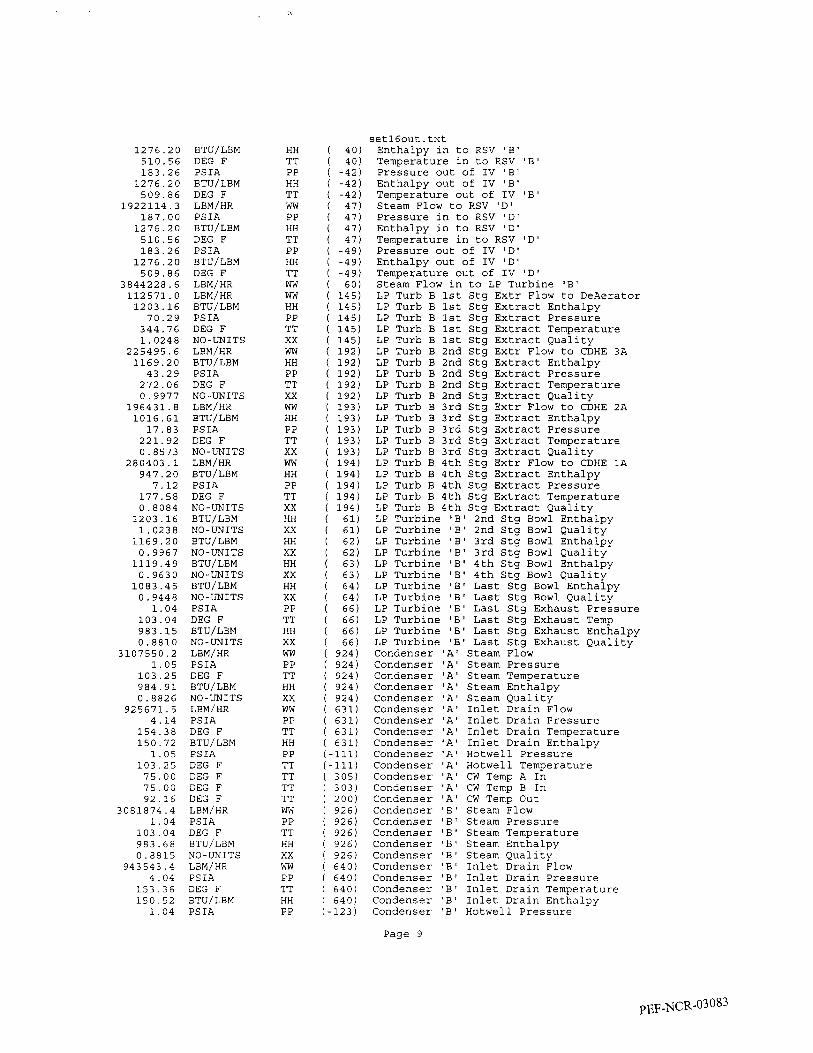
1276.20 510.56 183.26 1276.20 509.86
1922114.3 187.00 1276.20 510.56 183.26 1276.20 509.86
3844228.6 112571.0 1203.16 70.29
344.76 1.0248
225495.6 1169.20 43.29 272.06 0.9977
196431.8 1016.61 17.83
221.92 0.8573
280403.1 947.20 7.12
177.58 0.8084 1203.16 1.0238 1169.20 0.9967 1119.49 0.9630 1083.45 0.9448 1.04
103.04 983.15 0.8810
3107550.2 1.05
103.25 984.91 0.8826
925671.5 4.14
154.38 150.72 1.05
103.25 75.00 75.00 92.16
3081874.4 1.04
103.04 983.68 0.8815
943543.4 4.04
153.36 150.52 1.04
BTU/LBM DEG F PSIA BTU/LBM DEG F
PSIA BTU/LBM DEG F PSIA BTU/LBM DEG F LBM/HR
BTU/LBM PSIA DEG F
LBM/HR BTU/LBM PSIA DEG F
LBM/HR
LBM/HR
NO - UNITS
NO-UNITS LBM/HR BTU/LBM PSIA DEG F NO -UNITS LBM/HR BTU/LBM PSIA DEG F
BTU/LBM
BTU/LBM
BTU/LBM
NO - UNI TS
NO-UNITS
NO-UNITS
NO-UNITS BTU/LBM NO-UNITS PSIA DEG F BTU/LBM
LBM/HR PSIA DEG F BTU/LBM
NO- UNITS
NO-UNITS LBM/HR
BTU/LBM
PSIA DEG F
PSIA DEG F DEG F DEG F DEG F LEM/HR PSIA DEG F
NO - UNITS BTU/LBM
LBM/HR PS IA DEG F BTU/LBM PS IA
HH TT PP HH TT ww PP HH TT PP HH TT ww ww HH PP TT xx ww HH PP TT xx ww HH PP TT xx ww HH PP TT xx HH xx HH xx HH xx HH xx PP TT HH xx ww PP TT HH xx ww PP TT HH PP TT TT TT TT ww PP TT HH xx ww PP TT HH PP
setl6out.txt Enthalpy in to RSV 'B' Temperature in to RSV 'B' Pressure out of IV 'B' Enthalpy out of IV 'B' Temperature out of IV 'B' Steam Flow to RSV ID' Pressure in to RSV 'D' Enthalpy in to RSV 'D' Temperature in to RSV 'Dl Pressure out of IV ID' Enthalpy out of IV ID' Temperature out of IV 'DO Steam Flow in to LP Turbine 'B' LP Turb B 1st Stg Extr Flow to DeAerator LP Turb B 1st Stg Extract Enthalpy LP Turb B 1st Stg Extract Pressure LP Turb B 1st Stg Extract Temperature LP Turb B 1st Stg Extract Quality LP Turb B 2nd Stg Extr Flow to CDHE 3A LP Turb B 2nd Stg Extract Enthalpy LP Turb B 2nd Stg Extract Pressure LP Turb B 2nd Stg Extract Temperature LP Turb B 2nd Stg Extract Quality LP Turb B 3rd Stg Extr Flow to CDHE 2A LP Turb B 3rd Stg Extract Enthalpy LP Turb B 3rd Stg Extract Pressure LP Turb B 3rd Stg Extract Temperature LP Turb B 3rd Stg Extract Quality LP Turb B 4th Stg Extr Flow to CDHE 1A LP Turb B 4th Stg Extract Enthalpy LP Turb B 4th Stg Extract Pressure LP Turb B 4th Stg Extract Temperature LP Turb B 4th Stg Extract Quality LP Turbine 'B' 2nd Stg Bowl Enthalpy LP Turbine 'B' 2nd Stg Bowl Quality LP Turbine 'B' 3rd Stg Bowl Enthalpy LP Turbine 'B' 3rd Stg Bowl Quality LP Turbine 'B' 4th Stg Bowl Enthalpy LP Turbine 'B' 4th Stg Bowl Quality LP Turbine 'B' Last Stg Bowl Enthalpy LP Turbine 'B' Last Stg Bowl Quality LP Turbine 'B' Last Stg Exhaust Pressure LP Turbine 'B' Last Stg Exhaust Temp LP Turbine 'B' Last Stg Exhaust Enthalpy LP Turbine 'B' Last Stg Exhaust Quality Condenser 'A' Steam Flow Condenser 'A' Steam Pressure Condenser ' A ' Steam Temperature Condenser 'A' Steam Enthalpy Condenser 'A' Steam Quality Condenser 'A' Inlet Drain Flow Condenser ' A ' Inlet Drain Pressure Condenser 'A' Inlet Drain Temperature Condenser ' A ' Inlet Drain Enthalpy Condenser 'A' Hotwell Pressure Condenser 'A' Hotwell Temperature Condenser 'A' CW Temp A In Condenser 'A' CW Temp B In Condenser 'A' CW Temp Out Condenser 'B' Steam Flow Condenser 'B' Steam Pressure Condenser 'B' Steam Temperature Condenser ' € 3 ' Steam Enthalpy Condenser 'B' Steam Quality Condenser 'B' Inlet Drain Flow Condenser 'B' Inlet Drain Pressure Condenser 'B' Inlet Drain Temperature Condenser 'B' Inlet Drain Enthalpy Condenser 'B' Hotwell Pressure
Page 9

d w a
I i i
C"
El

El
El
El

v) 5
E e r
-
I I
t *I
I I
I

-
a
a P 0. P
I I
I
0
I I
I I
Y
I 1
1

I 2 I 3 I I 5 I 6 I 7 I 8 I 9 I B I C 1 , 1 - 1 1 1 1 3 1 1 1
I !I' lr I _ _ -
302 DRAWINGS H A Y NOT REFLECT ACTUAL
ARE CONTRCUED lHROUGH OPERATING PROCEDURES. NOCS (62816)
VALE pos lncms IN THE PLANT VALE POSITIMIS
PEF-NCR-03 08 8
c H P TURBINE I
--___ I
I H P FEEDWATER HEATERS

L
I I

1 I 2 I 3 I I I I I t
HYDROCEN INNER COOCED TURBINE GENERATOR
f I. I I I - € -
c-
302 DRAWINGS MAY NOT REFLECT ACTUAL V A L E POSITIONS I N THE PLANT VALVE POSITIONS M E CONTROLLED THROUGH OPERATING PROCEDURES. NOCS (62846)
n-- CRYSTAL RIVER PLANT
mn YLJ K6.w II 6 G MTEU FLOW DIAIXN GfNfRATOR PIPING
A. C. TURBINE GENERATOR
GAS DIAGRAM m u o m " N D m o * s * 8 w c u n c r
RmR;zG CAD w . v ~ - - - - - . * l f - m nA= .__
PEF-NCR-03090

I I I I I I I I I I I I I I I I I I I I I
0
I I
0
I L
1 I I L
>- I
r-
I I
3
1 I I I I I I I I I I I I I I I I

- r
"""- Q L 9 I * I L ,
d /
I t
I
L im
iinn*wm/ ' I 110 na a lW"8 8010W KLlM dWnd
110 lV3i015 N3308OAH I
I I I I I I I I I I I I I I I I I I I
I I I I I I I
01 C9100d I A3W
6 0 L 9 5 t C
I z I I

I
I I I I I I I I I I I I I I I
! I I I ! I I I I I I I I I I I I I I I I I I I I !
I ! I I I I I
I I I I I I i
I
I
I 2 I I I I I I I I XE" , PBel5iB J 5 6 8 9 e
W I flc -.!I
--$--1 I I
302 DRAWINGS MAY Nor REFLECT ACTUAL VAL- POSITIONS I N M E PLANT. VAL- POSITIONS ARE CONTROLLED THRWGH OPERATING PROCEDURES NOCS (62846)
I r *-I".
N R B I N E GLAND STEAM t DRAINS
I - - - - - - - - - _ _ _
PEF-NCR-03093
I - I
I I
- 1 I I
I - 1
I I I
I I I
- I I I I
E l
I I I
- 1 I I
D I
F I I I I
- 1 I I I
G I
I I i
- I I I I
* I
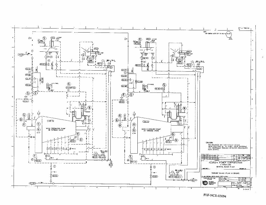
I I I I
i‘
I I I I I J _
.
I I I I I I I I I I I H- 10
i@
,

9Nldd LOOhYmOM m2.01 --ilk--
?-- xa 3" 0, ,A- - , r--1 I I I
WSN3ON03 WQUS ONVl3
I; - f' I
L
1
I I I I I I I I I I I I I I I I I

I I I I I I I I I I I I I I I I I I I I I I I I I I I I I I I I I I I I I I I I I I I. I I I I I I I I I- I I I
I I I L
1 I I I I I I I I
A
I I
w
I I
I I I I I I -1 I I I I I I I I -1 I I I I I I I I -1 I I I I I I I I I I I I I I I I

.@I I
I I 1 I 9 I S I I c z I
63 uH Wal dU W
"9 8,"
01 005100d h3Y 1 6

Y
0

I w
I
I
ul o\
, 0
m
, 3 9

I l
I o
. __ I
.- Y
I


I I
I I
I I
I

m
II
I I I
I

t
I-
- 4
I
-1 I 'I
21 I KI I I -1 I I I .I I I I I -1 I I I I I I I I I I I I I I I 1 I

I I I I-
I I I I I I I I I-
I I I I I'
I I I I-
I I I
I I I -1
1 I I I -
1
I I I -1
I I I I ,
I I I I
-I I I I I
*I
I I I
-I I I I I I I I I
-1 I I I I
'I
I I I _
I I I I I I I I I -1
I I I I I I I I _
I I I I 1 I I I I I I I I I I I I I -1
I I I -I El -1
-1 $1 31 -1 J

302 DRAWINGS MAY NOT REFLECT ACTUAL V A L M POSITIONS IN THE PLANT V A L E POS1T1oNS ARE CMITROLLED MROVGH OPERATING PROCEDURES NOCS (62846)
PEF-NCR-03 106

t I

SIEMENS
m l d d?h- ages. All nghb ale resewad in the word d lhs granl d a pal- en1 w M. reg. klralion d a VtUy mods1 or design.
Reactive Capability Curve
copying d Ihk doarmsnl and gkhg il lo dh- em and !he use or m u n i c a - Ion 01 the con- lenlr lhered. are forbidden
90(
::E;&? 80( leden ale I?- MVAR abb (0 (he WY-
70(
60C
50C
40C
3oa
200
100
0
100
200
300
400
500
GWERATOR-TYPE: THDD 17OffO-18
RATED GENERATOR OUTPUT S, = 989.400 MVA RATED ARMATURE VOLTAGE Ux = 22.000 kV RATED ARMATURE CURRENT IN = 25.965 kA RATED FREQUENCY FX = 60.0 HZ POWER FACTOR PF = 0.900 RATED HP-PRESSURE PE = 60.00 PSlG
3 PF 0.20 0.40 0.60 0.70 0.80
MVAR 600
700 0 PF 0.20 0.40 0.60 0.70 0.80 0.85
.. , - 1
2.1 -0500-7459/1 0990
Siemens Power Corporation J -1
p~F-NCR-0310~

SIEMENS
Job name Generator type Main exciter type Pilot exciter type
General Information Technical Data
Crystal River 3 Job No. 12- 7459 THDD 170/70-18 Serial No. 12 7459 Existing Serial No. 12 - E5 Existing Serial No. 12 - E7
Apparent power SN
Voltage UN
Current 'N
Field voltage u f Field current If
Frequency f N
Power factor P.F.
SDeed nN
989,4 MVA 22 *5% kV 25,965 kA
500 V 6340 A
0.9 60 HZ
1800 rDm Hydrogen gauge pressure pg
Phase sequence Direction of rotation
Stator F Rotor - Class of insulation
~
60 T psig Tl T2 T3 I Connection I Y
Clockwise/looking at drive end
Excitation system
Stator with two-layer lap winding
Cooling gas "2 Cold gas temperature 46 (115) Cooling gas volumetric flow V 61
1
OC (FO) m3/s
Terminal arrangement (lop view)
Exciter end
Siemens Power Corporation REVISION "0"
2.7-1 710-7459/1 0890
PEF-NCR-03 109

..

Turbogenerators Stator Slot Description 2-2Ear
- 1 1
- 12
- 13
I Stator core
Top ripple spring 5 Top strip 6 Semiconducting wrapper 7 Vertical separating strip 8 Top bar 9 Center filler
10 Bottom bar 1 1 Solid strand 1 2 Cooling ducl
MICOIOS~~C” insulation
Registered trade mark
7 I I l
!
2.1 -2303-0040 / 1 0489E
PEF-NCR-03 1 1 1

I 4
VleROMETER a OVERSPEED
t t PUMP
'ERENTIAL suer 4 'ANSION
PUMP TRr I DISCHARGE - PEDESTAL COVER
i .
7 I
,PEDESTAL END COVER 8 MICROMETER
GOV END - ,
PEDESTAL BASE id/ w
W
SECTION ''A''-'Y
- PEF-NCR-03 1 12
Bearing, Pedestal Assembly 725-1-333

I
i T PLkTE
.50 PIPE CONN. ON UNDERSIDE Of BLOCK TO AIR PILOT VLV.
1.00 PIPE CONN. ON UNDERSIDE
TEST GAUGES
3.50 PIPE,
1.50 PlPf
8.00 IN PUMP DIS
PIPE
PLAN VIEW I L * A * GOV END W I T H COVER REMOVED)

*a t
,r
m
YW
oc
so
*W
dt
W
Z
\ \
0- N
"
m
m
m
m
o_
2
I- o
W
v)
d,

W
z;; az
/

V

m 0
w a
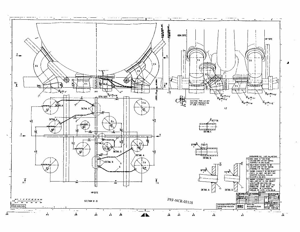
i i i I I I j 1 I 1 I i I i ! i I I I 1
t
e
P

L
I I I I
I I I
I I
l I 1
1-
9

W E I G H T S

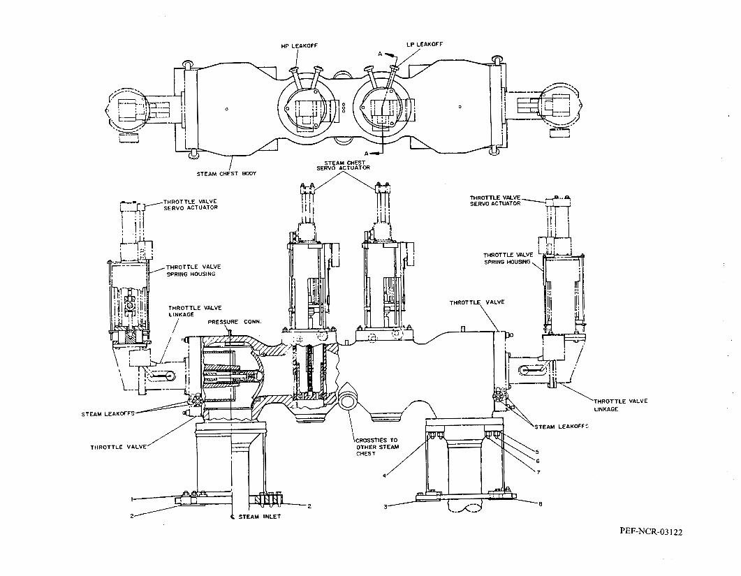
L P LEAKOFF HP LEAKOFF
‘THROTTLE VALVE LINKAGE
PEF-NCR-03 122

Spec Page #
17 Section Reference DESCRIPTION PRIORITY
1 121 I A 1 1 1 Thermal Kit 1
TYPE 8 SUBMITTAL DUE
DATE (WEEKS
I Final Quality Control Documentation I I I I I I I I I I including Shop Test and Inspection
5 Copies or 1 E
5 Copies or 1 E 5 Copies or 1 E
5 Copies or 1E
This is not part of Siemens standard deliverables since the turbine generator configuration does not
8 weeks RFDE change
8 weeks RFDE 4 weeks RFDE
8 weeks RFDE
8 weeks PTS
C 23 Terminal Point Locations -Mechanical 2
C 24 Terminal Point Locations -Electrical 2
X 25 ASME Pressure Vessel Certifications 2
C 26 Details 2 Generator Electrical Connection
,Generator Neutral Grounding Cubicle,
X General Arrangement Drawing for the
Proposed turbine generator startup 2 Turbine-GeneratorlMSR 2
QUANTITY 1 R F D E ~ ~ P T S ) I Comments 5 Copies or 1E 18 weeks RFDE 14 weeks PTS
C
C
A 4 and operating procedures 2 5 Engineering Schedule 2
6 Schedule 2 ProcuremenWProduction I Shipping
Recommended Detailed Erection I
I A l I 7 [Sequence 4
5 Copies or 1 E 1 12 weeks PTS I I
5 Copies or 1 E 5 Copies or 1E
5 Copies or 1 E 5 Copies or 1 E 5 Copies or 1 E 5 Copies or 1 E
6 months PTS 12 weeks PTS 4 weeks RFDE 6 weeks RFDE
3 months PTS
16 weeks RFDE 8 weeks RFDE
4 weeks RFDE 4 weeks RFDE
12 weeks RFDE 6 weeks RFDE
5 Copies or 1 E 8 weeks RFDE not applicable 5 Copies or 1E 6 weeks RFDE Please refer to TEI Proposal
C C
PEF-NCR-03 125
9 Reports 3
A 11 Shipping List 4 10 Generator Performance Data 3
Spare Parts List - Erection &
5 Copies or 1 E 5 Copies or 1E 5 Copies or 1E
2 weeks PTS 18 months RFDE 12 weeks PTS 6 weeks PTS

Spec
C
C
DESCRIPTION
, iterconnecting Piping General
X 36 material 37 Storage and Handling Procedures
38 Handling Equipment I Recommendations for Rigging and
Preliminary Instruction. Inspection
Final Instruction. Inspection and C 29 and Maintenance Manuals
I weeks RFDE 2 months RFDE
Progress Energy
Generator Charadenstic data and Phase Current Unbalance Calculatic Exciter model and tuning parameter for input to transmission PSS I E software
I I 41 I Foundation Drawings
I8 months RFDE
I weeks RFDE
I weeks RFDE
PRIORITY
This is proprietary information however.Siemens is willing to review this calculation with Progress Energy.
Further clarification required. Siemens does not intend to modify foundations.
2
7
4
2
2
2
TYPE 8 QUANTITY
Copies or 1 E
Copies
0 Copies Copies Copies or 1 E
Copies or 1 E ' Copies or 1 E , Copies + 1E
, Copies or 1 E I Copies or 1 E
, Copies or 1 E
t Copies or 1 E
1 Copies or 1 E
I Copies or 1 E
jUBMllTAL DUE
2 weeks RFDE
Progress Energy to clarify which interconnecting piping drawings are required Siemens will only supply hooa spray piping arrangement
8 months RFDE
6 weeks RFDE 1 weeks PTS Durin Pre-Outa e Plannin
Clarification is required from
2 months RFDE I I
PEF-NCR-03 126

OPC
ST 1 POD
#1 4
080009
BATES NOS. PEF-NCR- 03 123 THROUGH PEF-NCR-03 124
NON-RESPONSIVE

CR3 EPU Turbine Generator Bid Proposal Review:
Description: (Siemens Imstom: ]Notes: I I I
Generator Rating:
I I I
cost: ( Itr. (Itr. lSee Tony Owen Sheet I I I
1165 MVA using H2 inner cooled stator winding. Rating up to 1200 MVA possible (additional cost).
1173 MVA with H20 cooled mid- Both solutions meet minimum performance requirement. section replacement. Siemens will replace core iron. Alstom field rewind does 1162.5 MVA with H20 cooled stator not replace core iron. Siemens states core iron rewind. replacement is required. Why is core iron OK with alstom
1 (exhaust annulus has better performance).
Outaae Schedule: 69 days. Includes LP's and generator 75 days. Includes HP, LP's, MSRs rewind. Does not include MSRs. and Gen mid-section replacement.
Siemens schedule needs improvement. Need 2009 turbine building integrated schedule. Consider TG
Proposed Hardware: HP Turbine (full arc, full reaction, HP Turbine (partial arc, full impulse, Alstom requires HP Turbine and Generator to be opened replace in 2011). LP Turbines (46" replace in 2009). LP Turbines (47" for measurement during 15R. Estimated additional cost LSB or 56" LSB). Generator H2 inner LSB). Generator H20 cooled mid- 0 Alstom LP turbine does not replace inner cooled field rewind including core section replacement or field rewind cylinder, stationary blade carriers are replaced. New iron replacement. Generator rotor to (core iron not replaced). Generator stator cooling water skid and static excitation electrical be replaced. New brushless exciter. rotor sent out during outage for cabinets must be installed. Siemens solution requires all Replacement MSR vessels by TEI. refurbishment. New Static excitation generator heat load to be removed from H2 coolers. sc Digital Voltage Regulator (TCSA). system. system impact is large.
I I I
Notes: 1) Generator H2 pressure must be increased from 60 psig to 75 psig. Seal Oil System is impacted.
2 ) Evaluate Siemens 56" LSB LP Turbine Rotor Weight to present. 3) Proposed post installation plant performance test must be negotiated. Recommend simplified plant performance test due to amount of plant changes. 4) Need a dead band for performance guarantee bonus I penalty. 5 ) Alstom water cooled stator does appear to provide generator rating improvement. 6) Need to review HP Turbine full arc control capability for ICs main steam pressure control. 3% flow margin if accurately designed should provide enough throttling. 7) Siemens proposal does not include generator bushing replacement (estf%wor new bushins).
Recommend to evaluate Siemens Performance Plus H2 Seal Package.
I
% c''b a CONFIDENTIA!.
pEF-NCR-03 1z7

wostiingtlouse PPL Susquehanna, LLC
Turbine Upgrade Project Moves Forward
February 2,2001
On January 23, Frank Long, president, PPL Generation signed an agreement which keeps the turbine upgrade project moving forward. The agreement is for Siemens Westinghouse Power Corporation to design, manufacture, and install a turbine upgrade on Susquehanna Units 1 and 2. The turbine upgrades will improve service life, reduce maintenance, and increase each unit's efficiency by about 50 MWe. Craig Weeks, president, Siemens Westinghouse Global Service was the co-signer. Bob Byram, Bryce Shriver, and George Jones represented PPL Susquehanna at the signing.
After the signing, Bob Byram commented on the importance of this project for PPL and Susquehanna, "PPL is a growing company with generation being an important part of its growth strategy. This investment in Susquehanna reflects PPL's commitment to generation and its expectation of continually improving performance by SSES. These upgrades will add to our earnings contribution per share as soon as they go into service. However, only by us running safely and reliably will PPL derive the full benefit of this investment."
The plan is to install the first of the turbine upgrades during Unit 2's 1 I t h RIO in the spring of 2003 and the second during Unit 1's 13th RIO in the spring of 2004. Detailed preplanning has already begun for the first installation. How PPL Susquehanna and Siemens Westinghouse are going to get from signed agreement to installation was the topic of a presentation at the signing.
As outlined in this presentation, the keys to the project's success include applying and improving on the lessons Siemens Westinghouse has learned from previous installations including their installations at Limerick 1 and 2. They will also apply lessons learned from our Unit 2 installation to Unit 1. It was further pointed out that the planning and scheduling necessary for the safe and timely installations of the upgrades will affect the whole plant. Integrating the necessary work will require teamwork extending across most work groups and upward to the executive level.
Siemens Westinghouse has committed several executives to the success of this project. The most visible will be Richard Green, the Siemens Westinghouse site project manager. Richard will be co-located with the integrated Susquehanna and Siemens Westinghouse team at Susquehanna.
PEF-NCR-03 128

This transaction was conducted through Enporion, Inc. Enporion, Inc. is a new electronic procurement exchange serving the electric and gas industries. PPL Corp. is one of the founding members of Enporion.
Headquartered in Orlando, Florida, Siemens Westinghouse Power Corporation was created in 1998 when Siemens acquired Westinghouse Power Generation. Siemens Westinghouse specializes in power plant systems, turnkey solutions, and services that include the manufacture, repair, replacement, and upgrade of steam-, gas- and hydroelectric generators. Siemens Westinghouse also manufactures power-plant control systems, emissions monitoring and control equipment, and fuel cells.
Press Release given to PPL Susquehanna, LLC Employees on February 2,2001
-
PEF-NCR-03 129

t
SIEMENS
Quality Assurance Program
Awl 16,2007 =-, ,.
3emens &mWentral P~OORESS ENERGY Smwcr: COWANY, UCCRYSTAL R i m U ~ i r # 3 EWES7NO. S D 2 Z "
use th~s documenrsokly For thepurpose pwen Return upon reqwsl roduce or use orhenvise WIIIIOU~ the wmren consenr of Sjemens Power Generarron Inc
PEF-NCR-03 130

SIEMENS
w
MODERN~ZATION PROJECT Page 2 Quarry -m7-2 Apnl i 6 , 2007 P m m s s ENERGY SnvrcE COMPANY, UCCRYSTAL RIVER llNr7 113 Siemens Conridenfial
E W E S T N O SD22W7
Do nor disclose use lhis docuinenr solely For ihe purpose given Return uwn requesr
reproduce 01 bse oiherwisc mitiow Ihe wrmen cunscnt of Siemens Poww Generaiion fnc

k
SIEMENS E, CONFlDENTtdlS
Qually -2007-2 P n o ~ ~ ~ s s ENERGY Swvrcz COWANY, U C C R Y s 1 . u R m UNIT#^
M O O E R M Z 4 T W PROJECT page 3 semens Confldenfbl
E W E S 1 NO SD2XM7 Apni 16, 2007
Use this documenl solely FOI Ihe purpose given. Rerum upon request Do mi disclose reproduce or use orhenvise wrhour the wrinen comenr of Yemens Power Generarmn InC
PEF-NCR-03 132

SIEMENS CONFIDENTiX
MODERNRATKWPRWECT Page 4 Ouahly -Mo7-2 4pnlf6, 2007 Sief?lenS COrrfldenlt.31 PROGRESS ENERGY SERVKE COWANY, LLCCRYSTAL RIVE3 UNn 113
E W E S T N O SD2XXn
Use 011s docuinenl solely For lhe purpose o m m Rerurn upon reque9. Do mi disclose reproduce or use orbenvise wrhoul U,e wrmen mnsenc 01 Siemens Power Generarron Inc

Use chis documenr solely F o r rhepurpose given Rerum upon reqUeSL Do nor disclose reproduce or use orherwise wrrhour the wri7ren mmenr of Siemens Power Generalion Inc

. ...-
SIEMENS
,.IIY-.~...ll..l.. . ---- siemens C o n m l i a l PROGRESS E E ~ ~ G Y S E R W C E COWANY, ~ ~ C R Y S T A L RIVER U N I T ~ ~ .
CWESTNO SD22007 Apnlf6,2W7
Use this docuinenr solely For Ihe purpOSe given. Relurn upon I e q u e S L Do nor d,sclose reproduce or use orherwise withour Ihhe wrirren mnsenr of Siemens Power Generarmn InC.
PEF-NCR-03 135

MODH1NIUW PRWECT Apnl i6,2007
Quae& -2W7-2 PRGGRESS ENERGV S ~ I E COWANV, UCCRVSTAL R ~ M R UNIT 13
page 7 Semens ConTKknlial
EWESTNO SO22007
Use ults documenl solely F o r thepurpxse Owen Return upon requesL Do not Oisrlace reproduce 01 use o lhemsc withour the wrtnen ronsenr of Siemens Power Generarton tnc

Use drrs documenr solely For ;hepurpose Owen. Rerum upon request Do nor disclose reproduce or use oihennse wiihour the wrmen mnseni of Siemens Power Generaiion Inr
PEF-NCR-03 137

I
.- - SIEMENS
Page 9 Oua1w -2007-2 PROGRESS ENERGY SEXVICE COMPANY, U C C R Y S T A L RIVER U ~ r r A 3 Siemens C o ~ d e n l l a l
E W S T NO SO22007
Use Uris docuincnr solely For lhepurpose gwen Return upon ieqUeSL no noi d!scIuse reproduce or use oimmsc mmour UK wrnien consenr 01 Smnens Power Generxion Inc
PEF-NCR-03 13 8

I
M O O E R N ~ Z ~ T I O N PRWECT Apn7 16.2007
SIEMENS
Quahly -2007-2 P m ~ s s ENERGY Swvlu COWANY. LLCCRYSTAL R m U N ~ 13
E M S T N O SO22007
Page IO Siemens Conf!&nfral
Use Ihis docurnenr solely For Ihe purpose gmn. Rerurrr upon requesL Do nor disclose reproduce or 1158 orherwrse wrlhour Ore minen mnsenl 01 Siemens Power Generarmn Inr
PEF-NCR-03 139

CERTIFICATE OF APPROVAL
TGA-ZM-02-91-00

CERTIFICATE SCHEDULE
Deulscher AKltreditle rung s
--
TGA-ZM-02-91-00

CERTIFICATE SCHEDULE
S ie I iiet t s Po zuer G ett e ri7fio 11
Project Mtr nawertz en t Amcrjcm Renian Urinirdo - FL, USA
TGA-ZM-02-9 1-00 .

. . .
CERTIFICATE SCHEDULE
Sieitzcrzzs Power Gmerntioti
TGA-ZM-02-91-00

CERTIFICATE SCHEDULE
Sietricris Power Geizerafiosi

CERTIFICATE SCHEDULE
Sierttetzs Power Genercation
Pngc 5 qf5
001 PEF-NCR-03 146

MMPR ASSOCIATES INC. E N G I N E E R S
Limerick LP Turbine Replacement Rotors Proposed by Siemens Power Corporation
Evaluation of Margin With Respect to Disk SCC
December 1995
Prlncipal Contributors
L. E. Demlck J. Nichols
Prepared for
PECO Energy Company 965 Chesterbrook Blvd., 638-3
Wayne, PA 19087
ALEXANDRIA, VA 223 14-3238 703-5 19-0200 320 KING STT(EET FAX: 703-519-0224
PEF-NCR-03 147

ENMPR A S S O C I A T E S INC. E N G I N E E R S
W This enclosure inclrrdes conJidentialfnfomu&nation which is proprietaty to Siemns Power Corpora.h*on
and should be hndied accordingly.
REDACTED
-1- ,
PEF-NCR-03 148

.
OPC 1 st POD
080009
BATES NOS. PEF-NCR 03 149 THROUGH PEF-NCR-03 163
REDACTED

SIEMENS
PECo Energy Nuclear Steam Turbine Upgrade Limerick Generating Station-Units 1 and 2
Siemens Retrofit Increases Efficiency and Reduces Maintenance Costs
In January 1996, Siemens Power Corporation won the bid to replace six low-pressure (LP) tLJrbiileS, and two high- pressure (HP) turbines on Units 1 and 2 at PECo Energy's Limerick Generating Slation. When the retrofitting work is complctcd i r i 1999. I-imcrick Generating Station, currently rated at 2,100 MW. will have an extra 80 MW of capacity from the two GE boiling water nuclear reactors. To date, this is the largest
turbine retrofit project in Siemens Power Corporalion's history
The project will, according Lo PECo, provide the iitility with a quality, lony- term solution to stress corrosion probleins which have plagiied siinilar original equipment 1.P rotor units. The HP tur- bine replaceinent is being performed for the eficiency improvement. 111 addi- tion, the retrcfit will increase the plant's overall efficiency while rediiciny both short and long-term maintenance costs
Also, PECo has contracted with SPC to perform maintenance work on tlie Unit # I generator. ttiat Lvill be performed ai the retrofil installation.
Currently, Siemens is conducting a series of extensive project planning surveys and site inspections to prepare for thc project arid to ensure that thc: job can be corripleted in the 42-day breaker lo breaker outage plariried lor Unit I , April 1990 and ariottw outage planned for Unit 2 a year later.
PEF-NCR-03 164

SIEMENS
PECO Energy and Siemens Finish Major Steam Path Retrofit in Record Time Outage Duration and Scope Sets New Nuclear Industry Standard
ii1sl;~ila[ior\ of Sierncns raolacernenl HP lurbirie
At 1 1 33 PM on May 21, Sierncns Power Corporation's Fossil Division completed a record-setting outage with the replacement of the steam path for Limerick Generating Station's Unit 1 The turbine retrofit workscope which began April 3rd and was completed 15 hours
ahead of schedule wraps up the first phase of a project that will ultimately help 10 ensure that PECO Energy Co will inaintaiii its compet- itive edge in the newly deregulated energy md,ket
"PECO Energy Co , Siemens, and a large group of outside contractors
have set a new standard of cxccl- lence? in the nuclear industry by replacinq Unit Onc s four enorinoils turbines while refueling the reactor and doing maintenance on thou- sands of plant componerits and other systems,' said PECO Vice President Jim von Suskil
PEF-NCR-03 166

Siemens provided its state of the art turbine technology to replace the entire steam path of the existing 116&MW General Electric unit. The project scope included the replacement of the single high- pressure and three low-pressure turbines. as well as performance of a generator stator rewedge and other repairs.
Robert Atkinson, PECO project manager added, 7his was an out- standing accmplishment and a real tribute to Siemens and the quality effort performed by all of the personnel involved in the planning, design, component manufacturing and fabrication, installation and start-up activltles associated with this prqect'
Atkinson also offered these interest- ing statistics associated with the turbine retrofit project:
* The size of this work scope (three LP Turbines, one HP Turbine, plus Generator rewedgelmaintenance. all within an apprdmate 41 day work window) has established an industry record. This was the largest di f icat ion performed at Limerick Generating Station since the original plant construction.
-
The actual duration, from 'reactor scram' until 'unit on turning gear,' was approximately one hour shorter than the originally project- ed schedule of 41 days, 7 hours. This is despite an approximate 14-hour work delay due to ALERT issues. More than 500 people were involved with outage execution of the Turbine Retrofit work scope (not including the miscellaneous performance testing modifica- tions) expending over 200,OOO manhours. Approximately 1-1/2 miles of 114 inch stainless steel tracer test tubing were installed, along with 61 connections made to plant piping systems, in order to sup- port the tracer testing H h i will be performed in late fall as part of the ASME Performance test of the turbines. Approximately 114 welds were made on steam inlet lines, extrac- tion lines, and casing nozzles (sizes ranging from 10 inch
turbine projects for Siemens Power Corporation. 'We've had a group of engineers on slte for the last eight months developing a detailed schedule with PECO. The Siemens schedule for the turbine replace- ments had over 1,450 activities. Through our world wide manufac- turing organization, components were made in Germany and the US.' Thanks to the unique Siemens desjgn and to achievement of extremely close tolerances on rotor alignment, the start up went very smootdy. With no balancing needed, the turbine went directly from tum ing gear to synchrbnization without a hitch. For some manufacturers this would be, a notable achievement but for a Semens unit it is not at all out of the ordinary.
Siemens continues the manufacture of components for the Unit 2, which is scheduled for completion in May of 1999. The entire contract, which represents Siemens largest retrofit turbine order to date, will boost the capacity of this W u n i t phnt by
through 42 inch diameter) with only 2 minor reworks required.
more than 80 MW, and i l l extend Nuclear Regulatory Commission
from six to ten years. 'Planning for this endeavor began regulated turbit?€! j m o n inb'lds shortly after the contract was signed in January 1996,' stated Peter Hosbein, manager of steam
Slemens Power Corporation Fossil Division Headquarters 1040 South 70th Sbeet Milwaukee, WI 53214 Tel: 41414753600 Fax: 41414754040 http:/lwww.spd.siemens.cwn
Rinled h USA.
PEF-NCR-03 167

Nuclear BB961296 FA HP Modernization
Scope of supply You have made the decision to extend the operating license of your nuclear power plant for another 20 to 30 years. To help you maximize the life extension, including the financial return on your investment, Siemens Power Generation offers comprehensive solutions for your long- term operating goals. One solution, the Siemens Nuclear High Pressure Full Arc modernization for 88961296, is designed to increase operating plant generation through improved unit effectiveness.
The scope of this modernization includes:
H Monoblock HP rotor without thru-bore
H Latest technology double-flow optimized full reaction bladepath design
H Inlet admission ring
H New chrome steel inner cylinder
H Chrome steel blade rings
H L-Seal connection between inner and outer casings
and stationary blading. H Multi-strip inter-stage seals over rotating
A typical Siemens HP modernization encompasses design, manufacture and installation of the new bladepath. By eliminating the need for piping modifications and minimizing the modifications to the outer cylinder inlets, your new HP turbine bladepath can be installed during most standard reactor upgrades or refueling outages.
Siemens’ track record in replacing this nuclear HP turbine is outstanding in the industry, with over 1 5 turbine elements of this design replaced to date.
No thru-bore HP rotor eliminates need for rotor bore exominotions.
Customer benefits The modernization of your HP bladepath can significantly improve the effectiveness of your nuclear power plant by increasing megawatt output and lengthening inspection intervals. When combined with primary-side modernizations, the Siemens HP upgrade can help extend plant operating life by as much as 30 years or more.
H Custom designed and engineered to your
H Increased output includes minimizing flow
H Longer inspection intervals allow reduced
plant steam conditions
margins
maintenance costs (Siemens recommended inspection interval i s 100,000 operating hours)
H Increased resistance to erosion
H Enables additional modifications to match many future primary side enhancements
H Ease of installation.
PEF-NCR-03 168

Features Our engineers c~istom-desi!ln your HP bladepath based on the exact steam conditions at your site and your engineering requirements. They work closely wi th you and the primary side reactor supplier to collect engineering requirements a t the appropriate level of detdil, and prepare the engineering packages for your design change documentation and safety requirements.
Our thorough engineering evaluation process can deliver the information you need along with the necessary drawings to support your required design change documentation.
A key feature of this product offering i s the detailed information provided to support the operation and maintenance of your plant for the extended operating life.
Optional features: Radial-fit hydraulic coupl ing bolts eliminate "galling' in the existing body-fit coupling holes that can occur by utilizlng hydraulically unloaded sleeves between the coupling and bolt Quick bolt installation and removal is an added plus, helping to reduce outage duration.
Flow guide can be supplied in lieu of inlet admission ring for certain applications.
Optimized full reaction bladepath design improves effectiveness of HP turbine element
Published by and copyright 0 2006. Siemens Power Generation, inc. 4400 Alafaya Trail Orlando, FL 32826-2399, USA
Siemens AG Power Generation Freyeslebenstrasse 1 91058 Erlangen, Germany
www.siemens.com/powergeneratlon
Order No. A96001 -W90-A452-X-4A00 Printed in USA 1368COLMO2CDA01061.5
All Subject rights to reserved change without prior notice
Trademarks mentioned In this document are the property of Siemens AG. its affiliates. or their respective ownen.

L M a y s z i n e o f t h e S i e m e n s P o w e r G e n e r a t i o n G r o u p - __________
Tu r b o s e r v i c e Fewer Inspections and More Megawatts
throughTurbine Retrofits a t Nuclear Power Plant
Reprint from Power Journal l s u e 41’99
Power for Generations Sierneris Power Generation

I urboservice Fewer inspections and more megawatts through
turbine retrofits a t nuclear power plant
Disc cracking h a s been 3 probleni in n-IJny large low-
pressule disc-type t i~rbirie rotor designs, Instead of
frequent and costly inspections, a retrofit rotor with a more robust design provides the safer a n d more cost-
effective solution over the long term.
owpressure [LP) tur. bincs fur nuclear power plants often feature large rotors L rrtth shrink-fit discs.
These shnnks yield high tensile stresses, and stress COITDEIO~I cracking of the disc has thus been a problerri in many of such turbine rotor dcsigirs
MI C HA E 1 SM I A ROW 5 K I
Onre cracking IS initiated, f x - quent and costly inspections or even repiirs are required to prevent the cracking from pro- gressing to the chance of a sud- den disc burst and missile Ren- cratfon.Tkus In turn could dam. age plant-safety-rclntcd cquip ment
Turbine Retrofit is the Long-Term Solution
At Pottstown, Pr nn sylw ni 3, I'ECO Energy (PECO) operates !lit Lirwrick Gvrlt'tdtlrig Cjtd
tion, ;1 th?iling water rcartor plant with two unib that went inti, corrirriercial operalion in 19% and 1989 i c s p t t i v e i y Durine, routine maintenance tn jpxt ions ;it Limerick, indica- t w s of stress corros~ori crack ing at thc disc kcywqs 3rd hl id? attachment dcwtaii.; were detected on the orqi11.d
LP turbine rotor; Img-term re- iiability and economical open- tion of thc plant were thus p u ~ at serious risk. Additional long- term operational concerns in- cluded possible inner casing erosion arid intentage dia- phragrn erosion.
PECO evaluatrd the aitema- tives fox t~andling the problem: rotor rcpair a s rcquired. in- kjnd replacement, or upgraded replacement u f rotors. It was concludcd that an upgrade is the best sotution to nsolvc the rotor stress corrosion cracking concerns over the long term, Additionally, the new casings required f a r tlic upgrade would be more erosion resis- tant and the station would achieve add itiuna I clcct rical output. To further increase un i t efficiency and thus power output, PECO decided to re- place the high-prcssurc (HI') s t ea 171 1:) at h s, ton
In 1996, YECO awarded the Fossil Divisiuri vi Siemens POW. rr Corporation (now Sicincns Westinghouse) a contract to retrofit t h v steam turbines at Limcrick Getwattrig Station. The contract called f o r turnkey replacement of the FIP and three LP turbine rotors, and all ~ t n t i o n n i y bladir\g and inncr r a s i n p ot each unit.
NUClEAR ENERGY

NUCLEAR E N E R G Y
Ncw LP Rotors with Longer Inspection Cycles
I t
3
The new low.prcssure turbine rotors are more resistant to stress corrosion cracking and require fewer inspections. Together with the new inner casing5 they were also ;I major contribution to the 80.MW to ta l power output increase,
PEF-NCR-03 172

ccording ir3 the I . J i i c l t ~ i Regulatory Commission A (NRC) guideriries. turbirie
systems in l i . 5. riiJclc,qr ~CIWIY
plants must be designed al-ili
n'iairilained to ensure that the probability of gcncratirig d t i i r - bine missile is less that to 5 pcr year. She NRC thus requirrs rriaintaining a Turbine System Ma i r i t en a IKC (TSM) progra ni. hased on the niancifactufcr's calculation of niissilr genera- tion probabilities.
The original r ? ' i i ~ ~ i l e geneid.
i i a l wtor insycctioi> i i i terval o f
suit; ailov:ed PEL0 to increase t twr inspection intervals and val,,ie tcstiiig iri:.r~i.icncy frorri s i x 'years and weekly viiIve tcsting to
a ten-year irispection interval (87,600 operating hours) arid - a qudrterly valve testing fie- quency.
1 - k a fld ly,i s met hcdology and thc changes to thc present TSM program were forwarded to the NRC. The revised TSM
LIP 10 IOO,OOO hoiJrs, T h c ~ IC-
tion analysisfor the Linier rogram w a s approved ick Nucleclr Generation No op-eratiiig licensr. Station limited turbine change was required inspectior intervals to The NKC J I S O noted six years. The TSM pro- "Siemens tias u5ed the gram also included required same general bladc root intcrva,ais for perforrnirig in-ser. vice testing of valvcs: The mair turbine stop and combined in- termediate valves were tested once per 1wwk. Thc main tur. bine control valves were tested once per month.
Sicmcns providcd ar i upda t - ed missile probability arialysis to account for the ncw tcirbjne design, which supported an ini-
attachment for more t h a n thir- ty p a r s for both nuclear and fossil units. Some nuclear units are approaching aoo,ooo oper- ating hours without blade a t - tachment failures. l h i s pro. vides additional assurances that the modified limerick Generation Station tiirbine ro- to rs wil l perform iii service as designed."
PECO Bericfits fratti Retrofit and Short Installation Time


SIEMENS SIEMENS Westinghouse

SIEMENS
Ten-Disk Rotor - Since 1968
Replacement of Nuclear LP Turbine
Rotors and Inner Casings
Eight-Disk Rotor - Since 1987 Six-Disk Rotor - Since 1995
for presentation at the
AMERICAN POWER CONFERENCE I CHICAGO, ILLINOIS, APRIL 1-3, 1997
p~F-NcR-03 176

Authors
Mf. Heinrich Oeynhausen studied mechanical engineeririg at the State Engineering Academy in Essen. After graduating in 1971 he joined Kraftwerk Union where he worked as an engineer for applied mechanics for two years. After that, he continued his engineering studies at the Ruhr University, Bochum, and in 1977 became Scientific Assistant at the Institute for Mechanics. In 1981 he received his doctorate degree with a thesis on the stability of large clastoplastic deformations of thickwalled tubes under internal pressure and axial load. In 1984 he returned to Siemens/KWU and began working in the Steam Turbine Design Department, where he became manager in 1987. Mr. Oeynhausen was promoted in 1989 to head the subdivision of Steam Turbine Design, Since 1992 he has been Senior Director of the SiemenslKWU Steam Turbine Division with responsibility of all aspects of development, design, production and quality assurance.
Mr. Gerhard Roetrger studied Mechanical Engineering at the Eeuth Engineering Academy in Berlin. After graduation in 1957, he began
employment with AEG in the Turbine Mechanical Engineering Department. In 1964 he was appointed Manager of the Turbine Calculation Section
of the same Department. After Kraftwerk Union was founded, Mr. Roettger became Advisor for Development and Special Tasks in the Mechanical Engineering Department in 1974. He is engaged in Fracture Mechanic
Computation and Probabilistic studies. Recently, Mr. Roettger was involved in developing design, forging and manufacturing methods to further improve
the reliability of disk-type rotors leading to the introduction of the six-disk rotor design.
Mr. William E. Metide studied mechanical engineering at Oregon State University. After graduating in 1969 and a brief time working for the General Electric Company, he joined Allis Chatmers Power Systems in 1972 in the turbine-generator Product Service Division. Assigned as site manager for the installation of three prototype turbine-generator units for 400 MW, 650 MW fossil units and a 1305 MW nuclear unit, he was the lead turbine-generator start-up engineer on two new installations including a 650 MW fossil unit and a 1305 MW nuclear unit, He has been the site technical manager for 34 turbine-generator maintenance outages some with and some without labor contracts. He transferred to the failure analysis group in 1987 and evaluated turbine problems leading to predictive maintenance. In 1992 he transferred to his present position in service engineering and has been responsible for design control and manufacture of three large turbine upgrades including the six-disk LP rotor design.
Mr, Heinr Termuehlen studied mechanical engineering in Berlin. After graduating in 1958, he began employment with AEG, later Krafhverk
Union (KWU), in the Turbine Proposal and Project Department. In 1970 joined Allis-Chalmers Power Systems. In 1979 Mr. Termuehlen became Manager of Application Engineering with Utility Power Corporation in Bradenton, Florida.
Presently he is Chief Engineer and Director of Product Planning for Siemens Power Corporation in Milwaukee, Wisconsin. Mr. Termuehlen is a
member of ASME, IEEE, and ANS. In 1988, he was honored by being awarded the ASME Life Fellowship. He has presented several ASME, APC
and IEEE papers, two of which were honored with the 1980 and 1988 Prime Movers Award. Mr. Termuehlen is a member of the ASME Power
Division's Committee on Steam Turbines, and the International Representatives Committee, as well as the Industrial Committee
of the American Power Conference.

Replacement of Nuclear LP Turbine Rotors and Inner Casings
Introduction
At the American Power Conference in 1994, we presented a paper about the success of the replacement project at the Grafenrheinfeld Nuclear Power Station. The replace- ment of turbine rotors and inner casings with the latest development in steam flow paths design increased the output of this 1300 MW unit by 45.3 MW.I1l
In the meantime, improved flow path designs have been utilized in nuclear LP turbines worldwide, including the Grand Gulf Power Plant in Mississippi. The success has not just been related to the thermodynamic performance improvement but also design improvements for most reliable operation, and the mitigation of stress corrosion cracking have been in t rod~ced.~~ '~ l
Since the first LP rotor and inner casing replacement at the Connecticut Yankee Power Station in 1987141, further steps were taken to build the most harmonized LP turbine rotor and inner casing combination for nuclear power plants.
Disk-Type LPTurbine Rotor Design
Siemens has not experienced the exlensive stress corrosion cracking of disk-type rotors, as it was reported by EPRl in 1982 for other suppliers of nuclear LP turbines. Because of the excellent nuclear power plan1 experience with disk-type rotors since 1972, there was never the need to introduce another unproven rotor design.l51 However, over the last 25 years, an evolutional process was ap- plied leading from a ten (10)-disk over an eight (8)-disk to a six (6)-disk rotor design, as illustrated in Figure 1.
When, in the late 1960's, the first Siemens disk-type rotors for half-speed nuclear LP turbines were designed, operating experience from fossil units already existed, indicating that the proper shrink-fit design is critical for the successful long-term operation of such rotors.lfil At that time the ten-disk rotor was developed as a standard
I Ten-Disk Rotor Design
I
1968 -1 986: 57 Rotors Supplled
1987-1995: 29 Rotors Supplied
Since 1995: 10 Rotors Ordered
Figure 1. Evolution of Nuclear LP Turbine Design 2 in Operation
1 PEF-NCR-03 178

rotor for nuclear half-speed turbines. A total of 57 rotors of this design were built with features making them highly resistent against stress corrosion cra~king.[~l These features are illustrated in Figure 2 and listed as follows:
A larger than 1 mm (40 mils) gap between shaft and disks opens up the keyways and the circumferential stress relief groove to avoid crevice conditions.
Large radius of the stress relief grooves at the shaft and the disks are designed to mini- mize stress concenlrations.
The shaft contour is specifically designed for the lowest high-cycle fatigue stressing caused by shaft bending.
After EPRl reported about other original equipment manufacturer's (OEM's) stress corrosion cracking problems, Siemens introduced eight-disk rotors with further improvements as shown in Figure 3, with their design, forging and manufacturing modifications being summarized as follows:
compressive stresses in keyways compressive or low tensile surface stresses at the disk surface high fracture toughness within the disks low "Deep Seated" FATT) lower temperatures at all keyway locations
10"
Circumferential (0539 In.) Stress Relief Groove A
Shrink-Fit -c
Detall A I
Disk #5
Figure 2. Shrink-Fit and Keyway Configuration of LP Turbine Disk #5
I
Ten-Disk Rotor Design I I
2
7- Section B-6
Disk #1 Keyway Temperature 290OF (145%)
1 i n I I
Disk #I Keyway Temperature 230'F (110°C)
C . f r f
"1'
Measured Residual Stress Distribution of Shot
Peened Olsk Sudacc
Measured Residual Stnrs Distributlon Keyway
afier Rolling and Honing
Figure 3. Improvements of LP Turbine Rotor with Introduction of Eight-Disk Rotor Design
PEF-NcR-o~ 179

As of today, 29 rotors of this design have been
To further harmonize the nuclear disk-type rotor design, the six-disk rotor was introduced in 1995. This latest development was evolved from the previous ten-and eight-disk rotors to be used for all future new turbines and LP rotor replacement applications. Ten of the six-disk rotors have already been ordered to replace other OEM's LP turbine rotors.
Six-Disk Rotor Design
The evolutional development of the six-disk rotor from the eight-disk rotor is a logical step when comparing the two designs in Figure 4. The finite element grid shows that both rotors feature the same kind of blade attachments but different disk designs: The eight-disk rotor features
Figure 4. Finite Element Grids of Eight-Disk and Six-Disk Nuclear LP Turbine Rotors
two heavy (thick) and two slender (thin) disks per flow, whereas the six-disk rotor features three thick disks per flow. The similarity of the disk's operating conditions can best be seen in Figure 5 in which the operating stresses of the six-disk rotor are plotted. The maximum tensile stressing by centrifugal and shrink fit forces in the shrink fit zones of all disks is with about 525 Mpa (76 Ksi) the same. These stresses are the finite element calculation results which do not include the residual compressive stress which are built into all three disks per flow.
A major feature in mitigating potential stress corrosion cracking has been to build compressive stresses into the disks during the disk heat treatment process. This tech- nique has proven to be extremely successful with heavy or thick disks. With thickdisks, compressive stresses can be built deep into the disk from the surface and have been measured at a depth of 30" (1.2 inches). The finite element calculation results of local tangential stress levels are plotted for disks #1 in Figure 6. The first plot shows the stresses caused by the shrink fit and centrifu- gal forces at rated speed. The second plot reveals the build-in residual stress levels. Adding these two stress levels results in the third plot illustrating the actual oper- ating stresses. Important is to note the low stress levels at the disk's surface to prevent potential stress corrosion cracking. Additional methods have also been developed and are applied to build compressive stresses into the blade attachment zones. The result reveals that high ten- sile stressing only occurs at the forging center which is not exposed to stress corrosion conditions. Since all disks of the six-disk rotor are thick disks, the example of the disk #1 is representative for the remaining disks.
Based on 25 years of experience and finite element evalu- ation of temperature and stress distribution, it was concluded that keying the last two disks per flow is not needed. The shrink-fit under steady-state temperature conditions is strong enough to keep the disks in place, even if they are exposed to about 10 times the rated op- erating moment or an overspeed in excess of 133%.Tran- sient temperature conditions have only a minor effect on those last two disks per flow, since they are only exposed
525 MPa = 76 Ksi 450 MPa = 65 Ksi 375 MPa = 54 Ksi 75 MPa = -11Ksi
Figure 5. Tangential Stresses at Rated Speed Caused by Centrifugal Forces and Shrink-Fit of Six-Disk Rotor Design
PEF-NCR-03 180 3

Figure 6. Tangential Stresses in Disks # I of Six-Disk Rotors at Rated Speed
to low absolute temperatures (< 100°C or < 218"F), as shown in Figure 7. Transients can only occur in a small temperature range between these and the ambient tem- perature. However, the first disks per flow are exposed to higher operating temperatures and could possibly be exposed to larger temperature excursions especially at the upstream side. For this reason, it was decided not to eliminate the five keyways with keying pins of disks #I. The keyways of these disks feature the well-proven de- sign which is not exposed to any tensile operating stresses because of the applied rolling and honing process. It is also an open design without crevice formation. The upstream side of the disk fit has been modified by the introduction of an angled inner diameter. This design will move any potential moisture or impurities out of the shrink- fit region. In addition, it provides a smaller transition to the shrink-fit in the disk center.
Eliminating the keyways on disks #2 and #3 also
Figure 7. Isothermal Lines of Six-Disk LP Turbine Rotor
permits the designer to build the rotor shaft with smaller diameter steps between disks, resulting in a smaller in- ner diameter of disks #1 and #2, providing for a lower stressed shrink fit.
Introducing compressive stresses and reducing the effect of local stress risers has also been applied to the blade attachment and shaft of nuclear LP turbine rotors. Measures are applied to control any type of cracking, not only stress corrosion, but also high and low-cycle fatigue cracking.
Inner Casing Design
For building a LP turbine casing matching the rotor, the inner casing for the six-disk rotor features heavy casted inner casing sections as illustrated in Figure 8. The heavy disk #2 design could lead to heavier potential disk missiles penetrating the turbine casing. To mitigate this potential, the inner casing is built as a heay barrier for preventing potential disk missile penetration.
E Figure 8. Six-Disk Nuclear LP Turbine Design
4 PEF-NCR-03 18 1

Erosion-Corrosion and low-cycle fatigue could be a potential problem after long-term operation of inner casings. Based on experience the selection of proper materials such as high chromium steel tor LP turbine inner casing materials has eliminated erosion-corrosion problems. The single shell inner casing with blade carriers and diaphragms is exposed to low-cycle fatigue cracking if not properly designed and manufactured. The example in Figure 9 shows how low-cycle fatigue strength has been built into the inner casing. Evaluation of acceptable stress levels in its critical section such as the weld connections exposed to transient temperature conditions during unit start-ups was performed based on test results.
Operation and Maintenance
The six-disk rotor features a blade path design with the best possible thermodynamic performance. fjlpically, six
’Ibtt Location wlth High Thermal Stresses
Weld wlth .-?-. Backing
F
Detail A
too - M-
W -
m - 10- 110.
10- ¶a- zo - 10 -
Deslgn flange
- r loo0 loo00 1OOOOO
Number of Cycles
Figure 9. Low-Cycle Fatigue Test and Evaluation
to eight stages of integrally shrouded131 and three stages of free-standing[las 1 1 1 blades are provided as depicted in Figure 10 The three-dimensional flow path design and the more effective interstage and shaft sealing systems have improved the performance of nuclear LP turbines by 4% in overall unit heat rate, which accounts for about 50 MW increase in output for a 1200 MW nuclear power plant
Stress corrosion cracking has, for all practical purposes, been eliminated and the mean time between LP turbine inspections can be extended beyond the 100,000 operating hour threshold. As illustrated in Figure 11, the six-disk rotor provides sufficient space between the disks for good accessibility when performing a UT inspection. Having only six disks per rotor to inspect also reduces the inspection effort and time.
Conclusion
Presently, two of the ten ordered rotors have been in operation for 4,000 hours. Another two of those rotors are already shipped to a nuclear power plant in Spain.
Figure 10. Six-Disk Nuclear LP Turbine Rotor with lntegrally-Shrouded and Free-Standing Blades
Figure 11. Bladed Six-Disk Nuclear LP Turbine Rotor with Access between Disks
5 PEF-NCR-03 182

The latest evolutional step in designing the most reliable rotor and inner casing combination for nuclear LP turbines provides highest resistance against stress corrosion cracking. Together with the latest three dimensional flow path design features for stationary and rotating blading, an additional highest thermodynamic performance can be provided. For future new turbines and replacement applications, the six-disk rotor provides not only reliable long-term operation, but also requires a minimum of inspection and maintenance effort. Mean times between LP turbine inspections can be extended in excess of 100,000 operating hours.
The improved performance in regard to heat rate reduction and output increase by 4% over 1970 vintage nuclear LP turbine designs justifies a replacement of rotors in nuclear power plants based on the performance improvement alone, not even considering the large savings in O&M costs.
I
References
[ ’ I Weschenfeider, K.-D., Oeynhausen, H., Bergmann, D., Hosbein, I? and Termuehlen, H , “Turbine Steam Path Re- placement at the Grafenrheinfeld Nuclear Power Station”, Presented at the American Power Conference, Chicago, IL, April 25-27, 1994.
121 Rottger, G., David, W., Schleithoff, K., Hamel, H., and Termuehlen, H., “Disk-Type LP Turbine Rotor Experience”, Presented at the 1993 International Joint Power Generation Conference, Kansas City, MO.
l3J Termuehlen, H., and Schleithoff, K., ‘Advancements in Nuclear Steam Turbine Design to Prevent Corrosion”, Presented at the 1988 American Nuclear Society in San Diego, CA.
1‘1 Alkire, G., Galland, H., and Termuehlen, H., ”LP Turbine Rotor and Inner Casing Replacement”, Presented at the 1988 Joint Power Generation Conference, Philadelphia, PA.
Oeynhausen, H., Rottger, G., Ewald, U., Schleithoff, K., and Termuehlen, H,, “Reliable Disk-Type Rotors for Nuclear Power Plants”, Presented at the American Power Conference, Chicago, IL, April 27 - 29, 1987.
l61 Engelke, W., Jestrich. H., Schleithoff, K., and Termuehlen, H., “Design, Operating and Inspection Considerations to Control Stress Corrosion of LP Turbine Disks”, Proceedings of the American Power Conference, 1983, Vol. 45, pages 196-206.
1‘1 Jacobsen, G., Oeynhausen, H., and Termuehlen, H., ‘Advanced LP Turbine Installation at 1300 MW Power Station Untecweser”, Presented at the American Power Conference, Chicago, IL, April 29 - May 1, 1991.
IBI Termuehlen, H., Schleithoff, K., and Neumann, K., ‘Advanced Disk-Type LP Turbine Rotors”, Presented at the 1990 EPRl Workshop, Charlotte, NC.
l91 Termuehlen, H., “Thirty Years Experience with Integrally Shrouded Blades’, Presented at the 1989 Joint Power Generation Conference, Dallas, TX.
Jansen, M., Pfeiffer, R., and Termuehlen, H., ‘Advanced LP Turbine Blade Design”, Presented at the 1990 Joint Power Generation Conference, Boston, MA.
( ” 1 Gloger, M., Neumann, K., Bergmann, D., and Termuehlen, H., ‘Advanced LP Turbine Blading - A Reliable and Highly Efficient Design”, Presented at Ihe 1992 International Joint Power Generation Conference, Atlanta, GA.
6
PEF-NCR-03 183

~
Nuclear 1 3.9m2 LP Advanced Disc Design
Scope of supply You have made the decision to extend the operating license of your nuclear power plant another 30 years or more. Your next decision is to determine what investments in plant equipment provide you with the safest and most reliable improvement throughout the extended operating period.
Siemens Power Generation offers the most comprehensive solutions to maximize your assets. We can, with your selected primary side supplier, optimize the cycle improvements in accordance with all engineering requirements. We can coordinate, or lead, the BOP condition analysis and integration effort. We also can support the modification of your technical documentation to incorporate design modifications per your plant format. Finally, our proven high efficiency bladepaths will help you reduce maintenance costs and increase electrical output for the life of the plant.
Our 13.9" Siemens LP turbine features state-of- the-art design, technology and materials, with a 2.7 million-operating-hour track record of no disc stress corrosion cracking. This advanced disc LP design has been approved by the US Nuclear Regulatory Commission (NRC) for IO-year inspection in terva Is.
The typical 13.9m2 scope includes:
Fully bladed LP rotor with nominal 46-inch last row free-standing blades
New one-piece inner cylinder fabrication with advanced design stationary blading
Chrome steel materials in typical erosion areas
Carbon steel and coated carbon steel in lower velocity areas.
Customer benefits Our 13.9m' LP turbine can maximize your life extension t h roug h :
Performance improvements - ranging from 2% to 4% depending on cycle conditions
Improved reliability - US Nuclear Regulatory Commission approved for 10-year inspection intervals
Greater erosionlcorrosion protection - advanced technology coupled with proper material selection for your specific operating conditions
Reduced maintenance costs - 13.9rn' LP meets NRC missile probability requirements, reducing future rnaintenance inspections
Minimized installation and inspection t ime - one-piece inner cylinder enables faster and easier disasseniblylreassembly for inspection
Application for select non-OEM units - this proven design is the standard replacement for the 668116B281166381 LP family and has been installed on a number of General Electric nuclear LP turbines.

Features Bladed LP rotor Siemens‘ advanced disc dcsign rotor incorporates a boreless shaft and three shrunk-on discs per end. Material selection, foIying heat treatment and detailed design features are used to avoid stress corrosionicracking found on other disc design rotors.
New, one-piece inner cylinder fabrication The LP inner cylinder fabrication is constructed of the appropriate grades of steel a s needed for a target 40-year design life. Upgraded materials are available for high erosion environments, such as non-reheat BWR applications, in which more chrome steel content may be applied.
Advanced technology blading W Integrally shrouded high efficiency blading in
the early rotating and stationary stages
Latest integral shrouded taper and twisted design high efficiency blading used in longer blades
W Low pressure section blading matched and tuned featuring the freestanding 46-inch last stage blades, giving an exhaust area of approximately 13.9”
W Moisture removal features in the forward- leaning last-stage stationary bowed blades, which facilitates even loading and flow distribution and helps reduce erosion on the L-0 rotating blades
blades are flame hardened to further reduce moisture erosion.
W Leading edges of the LP freestanding rotating
References This improved LP design is engineered for the Westinghouse BB81, BB280, 88281, 86381 and certain General Electric nuclear LP turbine designs.
Longitudinal section o f modified L P with new internols.
Siemens Scope for CR3 Turbine Generator Retrofit:
Description: The Crystal River Unit 3 Nuclear Power Station (CR3) presently generates 903 MWe at 100% reactor power (2568 MWt). CR3 is planning to implement an extended reactor power uprate of 17% during the fall 2011 refueling outage. The CR3 steam generators will be replaced during the fall 2009 refueling outage. CR3 is also planning an “appendix K” feedwater flow measurement uncertainty recovery (MUR) uprate of approximately 1.6% reactor power during the fall 2007 refueling outage.
The scope of the CR3 extended power uprate (EPU) project is to retrofit the low pressure turbines, moisture separator reheaters, generator and the exciter during the fall 2009 refueling outage. The high pressure turbine will be designed and retrofit during the fall 201 1 reheling outage to support the reactor thermal uprated conditions.
The detailed scope of work is based on the description of the Work as set forth in: i) the Siemens offer (Proposal Number TA02-280) dated April 13, 2007; ii) the Proposal Revision e-mail TA02-280-1 dated May 18, 2007; iii) Puneet Bahl’s Installation Clarification e-mail and attachment dated June 4, 2007; iv) the requirements of this work authorization.
Schedule: Siemens has proposed a 63 day clearance window for the 2009 refueling outage scope of work and a 25 day clearance window for the 201 1 refueling outage scope of work.
The engineering document deliverable schedule shall be submitted for owner acceptance within 30 days of contract award.
The manufacturing schedule shall be submitted for owner acceptance within 60 days of contract award. Owner shall review detailed manufacturing schedule and identify Owner required witness points.
Siemens shall support Owners “engineering change process” and “work management process” as required, including attending engineering change design review meetings and work planning meetings.
Engineering: Siemens shall perform and submit to Owner, a detailed retained component study which shall include all turbine generator support systems and a bearing loading evaluation.
Siemens shall perform and submit to Owner, a torsional vibration analysis model of the turbine generator rotor train for the 2009 configuration and the 201 1 configuration. The torsional vibration analysis model report shall be submitted to the Nuclear Insurer (NEIL) by the Owner. Siemens shall resolve any NEIL requirements to support NEIL acceptance of the turbine generator torsional vibration analysis model.
Governor Valve Control Program Curves shall be provided to support the operation of the HP Turbine.
Siemens shall provide a lifting beam and slings designed to be capable of lifting all new turbine components supplied. The lifting beam shall be load tested and stamped with design load capability.
Complete new Turbine Generator Instruction Manuals (3 hard copies and 1 electronic copy), excluding AEH controller, shall be provided.
PEF-NCR-03 186

Performancc Guarantee and Testing: The 2009 pcrforniance guarantee (at 2.0 In. Hg. backpressure) and 201 1 performance guarantee (at 2.7 In. Hg. backpressure) shall be determined based on updated CR3 plant heat balance calculation. The CR3 plant heat balancc calculation shall be updated for final secondary plant design configuration and verified against actual plant performance following the 2007 measurement uncertainty recovery outage (i.e. at 2609 MWth.).
Plant performance testing shall be based on simplified ASME 6 procedure using test quality high accuracy instrumentation. Instrumentation Division of Responsibility (DOR) and Critical Test Corrections will be as mutually agreed on and as des'cribed in Siemens Amendment Offer dated May 18th, 2007.
Cycle isolation valve testing will be performed using the CR3 plant procedures and techniques (temperature differential and ultrasonic leak detection). Cycle isolation valve maintenance by PE will be by mutual agreement. Identified cycle isolation valve maintenance performed during the 20 1 1 outage may result in a small recoverable loss that should be accounted for (if greater than 0.5 Mwe, but no greater than 1 MWe) by mutual agreement based on Plant Thermal Performance Report.
Installation Services: Total Project Management: Siemens shall logistically manage all turbine deck work, crane usage and labor provided by PE to support turbine generator and MSR replacement project. PE to provide scaffolders, scaffolding materials, insulators, insulating materials, electricians, I&C, health physics. All other resources provided by Siemens.
Minor repairs that do not impact resources or resource loaded schedule shall be included.
LP Turbine laser alignment shall be performed during 2009 outage. The HP Turbine will not be opened in 2009 unless required to support alignment, at Siemens discretion. The HP turbine outer glands shall be removed to enable gland bore readings to support HP turbine alignment during the 2009 outage. The main oil pump shall be aligned during the 2009 outage. HP Turbine laser alignment shall be performed during 201 1 outage. Generator Alignment and Frame Foot Loading shall be performed during 2009 outage. New Generator alignment shims shall be provided or fabricated as required. Existing generator shims shall be consolidated and replaced with new shims.
Generator service shall include lowering the main leads box 6 inches to clean the flange and to pump the pumping groove. A generator ventilation test shall be performed and adjustments made to ensure generator ventilation meet design requirements.
Turbine service shall include replacement of turbine valves during the 2009 and 201 1 outage. 2TV's, 2GV's and 4 RSV's are scheduled to be replaced during the 2009 outage. 2TV's, 2GV's and 2IV's are scheduled to be replaced during the 201 1 outage.
All material and equipment required to support performance of turbine lube oil flush shall be provided.
All rental equipment (trailers, portable crane, forklift, etc) required to support project shall be provided.
All consumables including craft labor PPE, per Division of Responsibilities, shall be supplied.
Chemical control shall be in accordance with CR3 plant procedures.
PEF-NCR-03 187

Siemens Scope of Material Supply:
High Pressure Turbine: 0
0
0
0
0
0
0
0
0
0
Retrofit high pressure turbine shall be full reaction blading design with full arc steam admission. The steam path shall be designed with a 3% flow margin. Monoblock Rotor and Inner Cylinder with stainless steel Blade Carriers shall be supplied. Hydraulic Coupling Bolts shall be supplied and installed in the HP to LP turbine coupling with a new coupling spacer sized to axially position the HP rotor. The HP outer cylinder shall be reused and re-aligned as required. The Steam Lead Inlet Pipe Flanges shall be modified and new flexitalic gaskets installed. Stainless Steel Inner Glands Cases & Inner Gland Seal Rings sized for new rotor design clearance shall be supplied and installed. Outer Gland Seal Segments and bearing pedestal Oil Seal Strips shall be supplied, installed and final machined for the new rotor design clearances. The HP Turbine Bearings shall be rebabbitted. The existing extension shaft shall be refurbished at the Siemens Charlotte facility.
Low Pressure Turbines (Oty. 2): 0
0
0
Retrofit low pressure turbines shall be advanced disc rotor design with 56 inch last stage blades and 18 square meter exhaust annulus. Fully Bladed Rotor and single piece Inner Cylinder with stainless steel Blade Carriers shall be supplied and installed with standard inner cylinder bolting. Outer Gland Housings and Bearing Pedestal Oil Seals shall be supplied and installed. Outer Gland Seal Segments and the bearing pedestal Oil Seal Strips shall be final machined for the new rotor design clearances. Exhaust Flow Guides and exhaust hood spray nozzles and piping shall be supplied and installed. The LP Turbine Bearings shall be rebabbitted with TEGO babbit. LP1 to LP2 Jackshaft shall be supplied and installed with new standard coupling bolts and new coupling covers. New coupling spacers, including bull gear, to be supplied and sized to axially position rotors to design requirements. LP Turbine SS Rupture Discs (lead fiee) shall be supplied and installed.
0
0
0
0
Generator (1 200 MVA): The generator shall be rated at 1200 MVA. All replacement components shall be capable of supporting 1200 MVA capability. The generator H2 gas pressure shall be increased from 60 psig to 75 psig. A generator ventilation test shall be performed and adjustments made to ensure the generator H2 gas cooling capabilities meet design requirements. Supply and install all generator seal oil components required to support 75 psig H2 gas pressure. Seal oil system startup operation shall be documented to be in accordance with design requirements for 75 psig H2 gas pressure. Supply and install Hydrogen Inner Cooled RIGI-FLEX Winding. The stator winding shall include new Main Leads. Siemens shall be responsible for maintaining winding dryness. Winding shall be qualified by DC HI POT test. Supply and install Donut designed Stator Core. Core Iron Nitronic Through Bolts shall be supplied and installed. The new stator core shall be qualified by EL CID test and LOOP test. Supply and install Rewound Generator Rotor.

Supply and install generator Blower Assembly. Supply and Install four (4) H2 Coolers. Supply and Install Main Lead Bushings and Current Transformers. Supply and install H2 Gland Seal Rings and H2 Gland Housing Seal Strips. Supply and install Bearing Oil Catcher and Outer Oil Seal Strips. All generator rotor seals shall be final machined for new rotor design clearance. Generator Bearings shall be rebabbitted. 24 hot gas RTD’s, 4 cold gas RTD’s, 2 warm gas RTD’s, 2 rotor flux probes and 12 stator winding vibration probes shall be supplied and installed. All RTD’s shall be duplex, 100 Ohm Platinum. New generator instrument terminal boards shall be supplied and installed. All new generator instrumentation shall be wired to the new terminal boards.
Exciter: 0 Supply and install new Frame 12N Exciter assembly. New Exciter alignment shims shall be
provided or fabricated as required. Exciter base electrical connections shall be compatible-with existing field wiring and existing WTA voltage regulator. Supply and install new Exciter Housing including new Exciter Air Coolers. All cooler vent and drain tubing shall be stainless steel.

SIEMENS
CORRECTIVE ACHON PROGRAM
APRIL 16, zW7 Progress E m 5 y S a m Company, LLcCrys ta l Fwer UnR 83 Request No SO22007

SIEMENS
Mcdemizalivl PfWecd PAW 2 Corrective Action -2007-2 AFWL 16,2007 PmgresJ Energy Service Company, LLGOystaI Rhw UnX 173
Request No. SO22007 SIEMENS C o M m m n u
PEF-NCR-03 19 1

SIEMENS
Mcderniralkw prq'ed PAGE 3 CwmXive A c t i ~ -2007-2 APRIL 16, 2W7 Pmgress memy SeMce Company, LLcCrystal River Unn 13
Reqwsl No. SD22007 SIEMENS CONFlDENTuL
PEF-NCR-03 192

SIEMENS
PAGE 4 coneclive Action -2007-2 Progress Emfgy S e m Company, LlC-Cryslal RiwK Unlt #3
Rpquest No. SD22007 SIEMNS CONF~OENTU~
PEF-NCR-03 193

John L. Gibson Rcgioii Executive and Vice President Eastcrn US Sieriieris Power Geticration, Inc. 4400 Alal'aya Trail, M C Q-1 302 Orlando, FL, 32626
Dcar JoIiti,
Jiiiie 26, 2007
CONFIDENTlr?!.
PEF-NCR-03 195

Sincercly,
~ u c 1 . 4 . ~ Construction Progress Energy Florida, Inc.
Accepted and agreed to without condilion:
Title:. &*&ma - - *
Dale:
PEF-NCR-03 196


PEF-NCR-03 199

SIEMENS DESIGN TECHNOLOGY
INTRODUCTION

OPC 1 st POD
080009
BATES NOS. PEF-NCR 0320 1 THROUGH PEF-NCR-03 294
REDACTED

Siemens Power Generation Group "This document contains proprietary information. It is submitted in confidence and is to be used solely for the purpose for which it is furnished and returned upon request. This document and such information is not to be reproduced, transmitted, disclosed, or used otherwise in whole or in part without written authorization."
F! CONFIDENTII'.! u PEF-NCR-03295

Turbine Steam Purity Document No.: STIM-I 1.002 RevisiodDate: 2 2001-07-25
Siemens Power Generation Group "This document contains proprietary information. It is submitted in confidence and is to be used solely for the purpose for which it is furnished and returned upon request. This document and such information is not to be reproduced, transmitted, disclosed, or used otherwise in whole or in part
I- -, 3NFIDEM T//. without written authorization."
PEF-NCR-03296

Turbine Steam Purity Document No.: STIM-11.00'2 RevisionlDate: 2 2001-07-25
confidence and is to be used solely for the purpose for which it is furnished and returned upon request, This document and such information is not to be reproduced, transmitted, disclosed, or used othetwise in whole or in part without written authorization."
! b P b P & . . . , , ,
PEF-NCR-03297 ci;dtidtf'i 8 i r

Turbine Steam Purity Document No.: STIM-11.002 RevisiodDate: 2 2001-07-25 Page: 4 0 f 6
confidence and is to be used solely f i r the purpose for which it is furnished and returned upon request. This document and such information is not to be reproduced, transmitted, disclosed, or used otherwise in whole or in Dart

Turbine Steam Purity Document No.: STIM-11.002 RevisiorVDate: 2 2001-07-25
confidence and is to be used solely for the purpose for which it is furnished and returned upon request. This document and such information is not to be reproduced, transmitted, disclosed, or used otherwise in whole or in part without written authorization."
PEF-NCR-03299

Turbine Steam Purity Document No.: STIM-11.002 RevisioniDate: 2 2001-07-25
confidence and is to be used solely for the purpose for which it is furnished and returned upon request. This document and such information is not to be reproduced, transmitted, disclosed, or used otherwise in whole or in part without written authorization."
PEF-NCR-03 3 00

-.r
-
m
(7
mo
1


CR3 Turbine Generator Retrofit Plant Performance Testing, Conference Call Notes, 05/16/07
Attendees: PE: Ted Williams, Scott Deahna, Dario Zuloaga Siemens: Dan Smith, Puneet Bald, A1 Battista, Jay Meyer, Dave Cavanaugh
Follow-up Items: 0 The Siemens proposal “Electrical Output Guarantee” is based on the post 201 1 electrical output only.
A post 2009 performance test will be performed to document plant performance and to compare to the heat balance estimated electrical output. A test measurement uncertainty will not be applied to the 2009 measured and corrected megawatt output. The “electrical output guarantee” will be calculated as follows with provisions made to correct for 201 1 maintenance recoverable cycle isolation losses as mutually agreed.
Jay Meyer to provide Dario Zuloaga basis for 0.6% test uncertainty and to review test uncertainty for 2011 test. PE will test cycle isolation valves as described below. Cycle isolation valve maintenance by PE will be by mutual agreement not as required by Siemens. Siemens to reduce proposal cost for plant performance testing.
(Post 2009 MW corrected + (post 201 1 MW corrected - pre 201 1 MW corrected)) +/- (agreed uncertainty). 0
0
0
Summary: General agreement was reached to perform a simplified ASME type plant performance test to assess the estimated turbine retrofit performance following the 2009 LP turbine / MSR / Steam Generator replacement and to assess the guaranteed performance following the 201 1 HP turbine / reactor thermal uprate. PE and Siemens will work to obtain accurate plant heat balance model for EPU. Siemens can estimate the 2009 electrical output at 2.0 In. Hg. condenser pressure and the guaranteed 201 1 electrical output at 2.7 In Hg condenser pressure. The bonus / penalty can be reduced fiomm’KW to-KW
. a CONFIDENTIR!. +&& Primary test measurements to include: reactor thermal, feedwater flow (Cadon LEFM), electrical power, turbine backpressure (basket tips), turbine throttle pressure (at throttle valves), feedwater temperature, MSR TTD, MSR pressure drop, feed pump turbine steam flow (?).
Siemens proposes a 0.6% test uncertainty. Jay agreed to provide Dario the basis for this test uncertainty. PE would like a +/- approximately 5MW output band due to extensive plant modifications.
Discussion item: How to address 2 year cycle between 2009 LP retrofit and 201 1 HP retrofit / EPU.
Post 2009 MW corrected test data will be compared to heat balance MW estimate for phase 1. Siemens proposes to perform a pre 201 1 test to determine the plant output change during the cycle. Although this change is expected to be small, the source of the change (i.e. LP turbine, cycle isolation, etc.) may not be known and may be outage recoverable (cycle isolation maintenance) during 201 1. Identified cycle isolation maintenance recoverable losses are expected to be small, but should be accounted for based on mutual agreement.
Cycle Isolation: CR3 utilizes a plant procedure that measures temperature difference across cycle isolation valves. Ultrasonic leak detection is also utilized. The procedure is performed quarterly by the plant engineers. PE proposes to use these techniques to determine potential cycle isolation valve leakage. PE and Siemens will “mutually agree” to any cycle isolation valve maintenance to be performed by PE.
PEF-NCR-03305
SIEMENS
POTENTIAL SUB-SUPPLIER LIST

SIEMENS
Mcdemfakw hold PAGE 2 Main S w l i s l - 2 0 0 7 - 2 PROGRESS ENERGY SEWCZ GXPAW, LLGCR'fsra R m UNIT#^
REWEST No. SO22007 APRIL 16, 2W7 SIEMNS coNmomn,u
USE T M S DOCUMENT SOLELY FOR W E PWPOSE GW€N. RErURN UPON REQUEST. Do Nor MSUOSE REPROOUCE OR USE oMRmsE m o u r WE W R I ~ N coNsoir OF SIMMS POWER GEiiEmnO)i INC
PEF-NCR-03307

SIEMENS

Siemens Turbine Generator Power Uprate Retrofit Meeting Sept. 12,2006
The Crystal River 3 Nuclear Power Station is considering a 17% reactor thermal (20% electrical) power uprate in 201 1. The unit steam generators will be replaced during an 85 day outage in 2009. The present reactor thermal power is 2568MWt. The present turbine throttle steam conditions are 10.5MPPH, 900 psig, 585F. Turbine first stage pressure is approximately 700 psig. The seasonal turbine backpressure ranges 1.5 - 3.2 IN HGA. The present backpressure design point is 2 IN HGA. I believe a new backpressure design point of 2.2 - 2.3 IN HGA will be recommended following analysis of the average operating backpressure and the cost of power. The electric generator is H2 inner cooled (60 psig), 989 MVA, 0.9 PF. Frame 126 x 275. CR3 presently generates 900 MW at 100% reactor power.
Recommended agenda: Review lead time requirements, budget estimates and estimated efficiency gains from new technology. Discuss Siemens HP Turbine retrofit technology. If HP turbine is retrofit during 2009, would increased throttling losses be expected to be greater than the technology efficiency gains for the one cycle of operation prior to the reactor thermal uprate? Discuss Siemens LP Turbine retrofit technology. Discuss Siemens Water Cooled Generator Stator retrofit technology. Is it possible to uprate a 989 MVA H2 inner cooled generator to >1100 MVA by increasing the H2 pressure, etc? What are the uprate limitations for H2 inner cooled machines? Discuss Siemens Exciter and Voltage Regulator retrofit technology.
0
0
0
0
0
e
PEF-NCR-03309

Siemens Proposal #SD22007, CR3 Turbine Generator Retrofit 5/3/07 Review Meeting Open Items
Siemens to provide proposal amendment letter by 05/18/07. Siemens to provide 1200 MVA generator component evaluation by 06/08/07.
Pg. 1 o f 2
Generator field installation schedule is 69 days, including 48 days for generator stator winding and core iron replacement working 24 x 7. Siemens to review generator schedule for potential improvement. If generator outage schedule does not fit inside revised plant steam generator replacement schedule, then evaluate stator midsection replacement. Siemens mentioned the possibility of a seed stator fiame becoming available.
Include generator main lead bushing replacement in proposal.
Include in proposal at no additional cost: 0
e
e
e
e
0
0
e
0
e
Replace generator H2 seal rings and seal strips on H2 gland, bearing oil catcher and outer oil seal. Generator Ventilation Testing. Add description of requirements. Complete rotor train center line laser alignment and generator frame foot loading alignment. Replacement of the HP turbine gland steam spillover control valve with larger capacity valve. Machining of the HP turbine steam lead inlet flanges for flexitalic gasket modification. Rebabbit HP turbine and generator bearings due to new rotor journals. New style LP turbine lead free rupture discs. Lowering of the generator leads box to clean and pump sealing groove. A complete new technical manual for the turbine generator (excluding the AEH controller volumes) and electronic spare parts catalog. Material to support lube oil flush.
Project Manapement: PE desires “turn key” project management with minimal PE support responsibilities. Siemens to provide millwrights, riggers, welders, pipe fitters, crane operators and winders. TEI may provide the craft to install the MSRs. Siemens overall project management to include control of additional support craft provided by PE (mechanics, electricians, I&C, scaffold, insulators, pipe fitters, health physics, laborers, confined space attendants, fire watch, etc.). This will eliminate any delays due to “support requirements by others”. Siemens to discuss this concept with their contracts personnel and provide their position.
Proposal pricing include?&&) for ASME PTC 6 turbine performance testing. Following discussion the prevailing approach is not to perfom a full ASME PTC 6 performance test. Consideration is to use the PTC 6 - 2004 Alternate Test. Key parameters will be megawatt output and reactor thermal. PE will have high accuracy instruments for feedwater flow, main steam pressure, main steam RTD’s, condenser back pressure and high accuracy megawatt meters. This approach will reduce the price included to perform the full PTC 6.
Performance bonus / uenaltv clause should have a performance dead band. Review dollars tied to performance testing result. The fact that the multiple changes to the plant will make exact megawatt contribution from a single source difficult to evaluate. A deadband of +/- 0.7% (test accuracy) could be set to account for these uncertainties and then a bonus could be considered for megawatts achieved above that value.
Is replacement of the generator WTA voltape regulator required to support the 1200MVA generator rating excitation requirements? WTA power amp drawers are uprated from 200 amps to 300 amps. Are the power amp drawers fully redundant at 300 amps? Siemens to unbundle the Digital Voltage Regulator and price it separately. Provide basis for recommending the EM1 / RFI hardened cabinets. Estimated cost for AVR replacement is(&- including installation and startup support.
Existing generator rotor must be returned to Siemens. Transportation costs are included in the current price to return the existing CR3 generator rotor back to Charlotte.
--%&&

Siemens Proposal #SD22007, CR3 Turbine Generator Retrofit 5/3/07 Review MeetinP Open Items
Shipping and Handling estimated costs are high. Heavy hauling on site is largest cost portion. Agree to review transportation and handling plan. Evaluate Mammoat (bundled contract) for on site heavy hauling.
Pg. 2 of 2
The final Secondary Plant design configuration must be provided to Siemens to support turbine blade path design. This includes the MSR drains re-route and feed water heater specifications. Siemens to provide a date when the information is needed for the final turbine steam path design.
Siemens to evaluate the remaining turbine generator equipment and support systems for EPU impact. The basis for this c o s & q i s the number of hours projected to perform the study. PE asked to re-consider the magnitude of this expenx in light of all the other work required to define the turbine peripherals as baseline to the overall project.
Add generator “Performance Plus H2 Seal Package” to proposal. Document added advantage / benefit fiom purchasing this seal package. Identify large generators with performance plus seal installed.
Siemens will provide dehumidification for the generator and no delays of high pot testing due to winding moisture. Electrical Power required for generato; core iron loop test will be by PE.
Generator instrumentation will include installation of two flux probes, fiber optic vibration probes and 24 Gas Discharge RTD’s with new terminal boards. Flux probes and fiber optic vibration pickups will be monitored using portable test equipment. Include providing the required portable test equipment for monitoring. Partial discharge slot coupler pickups are not required.
The seal oil skid will be modified to support 75psi generator H2 pressure. Any modifications required to enable the seal oil skid to operate at this pressure is included in current price.
The Generator Neutral Transformer will be included in the Siemens electrical evaluation for 1200MVA generator short circuit conditions. Generator protective relay set points will be provided.
All LP cylinder alignment and installation features (material and modifications) to install new turbines are included in proposal.
All HP turbine cylinder steam seal surfaces will be checked and machined as necessary. This work is included in the current price.
The extra charge for traveling personnel was defined as the per diem and mobilization costs that could occur to bring in some of the Siemens “regular” craftsman similar to AREVA specialty welders. This will be further defined by Siemens.
Progress Energy access to the manufacturing facilities cannot be limited to just five visits for HP and LP turbines.
LP turbine construction “is final design dependent and Siemens reserves the right to make changes to the number and style of components noted above without impact to performance guarantee values.” “Price” to be added to the statement.
CONFIDENTIP,!
Siemens Proposal ## SD22007, CR3 EPU Turbine Generator Retrofit MeetinP Notes from 05/03/07: Pg. 1 of 10
Purpose of the Meeting is to better understand the Technical and Commercial Provisions of the contract proposal, ensure that various studies and analysis remaining do not alter the cost of the proposal and convey the understanding that the schedule must be improved to perform EPUR within the SGR schedule.
Siemens Proposal Summan: HP Turbine: replace in 201 1 with full arc, full reaction turbine design with 3% flow margin. LP Turbines: replace in 2009 with 13.9M2 (46”LSB) or 18M2 (56”LSB) turbines. Generator Stator: field rewind stator in 2009 with H2 inner cooled winding, core iron is replaced. Stator rating is 1 165MVA to be further evaluated to obtain 1200 MVA. Generator Rotor: replace rotor in 2009 with new or rewound seed rotor. Rotor winding is re-designed for 1200 MVA. Exciter: replace in 2009 with larger frame 12N exciter designed to support 1200 MVA generator rating. Voltage Regulator: replace in 2009 with TCSA digital voltage regulator designed to support 1200 MVA generator rating. Moisture Separator Reheaters: replace MSR vessels in 2009 with TEI supplied MSR’s.
Performance Guarantee: 1082.9 MW @ 2.7 In Hg (1 8M2 LP turbine). Does not include MSR drain reroute.
Outage Schedule: 2009 schedule indicated 69 days for LP turbine replacement and generator stator rewind. MSR replacement is not included.
Meeting Summary Highlights: Siemens to provide proposal amendment letter by 05/18/07. Siemens to provide 1200 MVA generator component evaluation by 06/08/07. Field installation schedule is 69 days, including 48 days for generator stator winding and core iron replacement working 24 x 7. Ted asked for review to shorten schedule. Mike O’Leary feels much generator schedule improvement is probably not achievable. May need to evaluate cost of stator midsection replacement if outage schedule is not acceptable. Siemens mentioned the possibility of a seed stator frame becoming available. Generator core iron field replacement loop test requires 4160V, 850A, Single Phase power supply. The plant must provide this power
Generator Ventilation Testing is required. Must roll unit to !A and 1/3 speed with air in the generator. 8 pressure taps installed throughout generator. Must restore generator following test. This must be included in plant startup schedule. Can auxiliary steam supply main steam to roll turbine early? The High Pressure Turbine should be acceptable for operation during the 2009 to 201 1 non-outage period.
supply.

Siemens Proposal # SD22007, CR3 EPU Turbine Generator Retrofit Meeting Notes from 05/03/07: Pg. 2 of 10
Scope of Supply Comments:
w - Verify the Generator Main Lead Bushings are the only material not included in proposal required to support generator 1 165MVA rating.
& Shay Foley indicated that offer was based on all major equipment sized to perform at 1200MVA. Thls included the core iron, stator, exciter and rotor. The blower should capable of meeting the 1200mva rating with modificatiodadjustment. The engineering study to be completed by June 8* will verify the correct bushing sizing and cost. Cost estimate for the bushings isl_DE_DpCmD Commitment was not clearly made to include this cost in the current price.
Proposal states generator rotor seal sizes may be impacted by new rotor. Include re-stripping the hydrogen gland bracket, bearing oil catcher and outer oil seals. Include replacing H2 seal rings or installing new performance plus H2 gland seals.
- Re: Siemens agreed that the hydrogen seal rings and all seal strips should be replaced because the rotor was being replaced. Need to include replacing all generator rotor seals in the proposal. Inclusion of the new performance package was not affirmed. Siemens wants to sell this package but could not provide sufficient basis to move it fi-om nice to have to required status. The conventional seal package will function at the higher 75 psi hydrogen pressure. The SC Cooling System should be based on ambient temperatures at 95 degrees Fahrenheit.
All LP cylinder alignment and installation features (material and modifications) to install new turbines must be included. ABB LP turbine retrofit removed the lower diaphragm ring, adaptor pipe and modified the top adaptor ring. All material to connect the inner cylinder to the cross over tee piece must be included.
- Re: Siemens agreed with this statement. A new top diaphragm ring is included in scope.
The retrofit is considered a major project with enormous cost. As stated in your proposal the project will be well engineered and will address issues to assure long life and reliable operation. Therefore we expect the following to be included in the retrofit project: Replacement of the HP turbine gland steam spillover control valve with larger capacity valve.
Machining of the HP turbine steam lead inlet flanges for flexitalic gasket modification.
HP turbine exhaust bowl erosion protection (spray pro?).
- Re: Initially Siemens rejected inclusion of this valve, but later Siemens agreed to include this valve in their proposal (and price).
- Re: Machining of the steam lead inlet flanges for fitment of flexitalic gaskets (phonographic surface) will be included at current price.
- Re: It has not been determined that erosion has occurred but the long maintenance intervals currently scheduled do not allow for degradation to be caught if it were initiated. Siemens reiterated that the superheated steam is much less erosion than wetter steam. The erosion protection remains a consideration for as a “contingency” but it will not be included in the current contract price.
- Re: Bearing babbit condition will be evaluated and rebabbiting will be performed as necessary. Request HP and Gen bearing rebabbit as base scope.
- Re: Siemens has the new lead free, stainless steel rupture disc and will include in the proposal at current price.
- Re: Siemens will perform this work as part of the proposal. Current Transformers are lower mass and will lessen vibration.
Rebabbit the HP turbine and generator bearings due to new rotor journals.
New style LP turbine lead free rupture discs.
Lowering of the generator leads box to clean and pump sealing groove. (Seal Tite contains asbestos).
PEF-NCR-033 13

Siemens Proposal ## SD22007, CR3 EPU Turbine Generator Retrofit Meeting Notes from 05/03/07: Pg. 3 of 10
Scope of Supply Comments Cont:
New Rotor Lifting Beam. Certified for load rating? Include new lifting slings for rotors. - Re: Slings are included.
Include a complete new technical manual for the turbine generator (excluding the AEH controller volumes) that includes residual equipment left installed after retrofit. Include electronic parts catalog. Proposal includes new technical manual leaflets only.
Re: Siemens complained about the amount of work and presented several issues with providing this. In the end they will provide a new manual.
Review new generator instrumentation and monitoring systems. Include 2 flux probes and 2 PD slot couplers to be installed. These probes will most likely be monitored using hand held instruments. Is a new Environment One generator condition monitor (GCM) provided? How many stator hot gas RTD’s are provided?
- Re: Siemens will provide the two flux probes, fiber optic vibration probes and 24 Gas Discharge RTD’s (12 coils with 2 monitoring points per coil). New terminal boards for instrumentation are included. Siemens recommends partial discharge bus couplers (IRUS) rather than slot couplers. A GCM is not included.
Is stator end winding vibration monitoring recommended for a rigi-flex winding? Can FOVM probes be monitored using portable monitor? FOVM is optional scope in proposal.
- Re: Rotor flux probes and FO vibration probes can be monitored using portable test equipment. These probes are recommended by Siemens. Siemens does not recommend partial discharge monitoring.
PEF-NCR-033 14

Siemens Proposal # SD22007, CR3 EPU Turbine Generator Retrofit Meeting Notes from 05/03/07: Pg. 4 of 10
Engineering Comments:
LP Turbine Rotor Weight for 18M2 Rotor is 350,000 lbs. LP rotor plus jackshaft weight loads bearing #4 and #5 over 300 psi. A bearing loading evaluation must be completed prior to award. Original BB281 LP rotors weight was 195,500 lbs.
Re: This is not considered to be an issue. Evaluation will not be completed prior to contract award. Siemens is confident bearing loading is acceptable.
What is “TEGO” babbit for LP turbine bearing? Does it support higher loads or higher temperatures? - Re: This material will support higher loads and temperature. TEGO babbit is higher strength and is lead free. This material has been used on similar type frame supports.
Complete Generator 1200 MVA rating evaluation and identify impact prior to award. - Re: This will be done by June 8”.
Generator H2 Pressure increases to 75 psig. Qualifying the generator frame to 75 psig shall be performed prior to award. Re: This will not be done prior to award. This was looked at initially and should be acceptable.
Rotor train alignment is critical to reduce bearing stress and vibration. Proposal states alignment calculation is affected by rotor stiffness, bearing support structure movement and cylinder cover installation. Should a cylinder tops on / tops off alignment check be recommended since this will be the first BB281 frame the 18M2 LP turbines may be installed in?
Re: Complete center line, laser alignment will be done and included in the current price. The new Cantenary Curves will also require the alignment. Need to include generator frame foot loading in base scope to support generator realignment.
Generator H2 pressure increase to 75 psig. Recommend implementing performance plus H2 seal package. Proposal should discuss benefit to seal oil system performance and H2 purity. Are modifications to existing seal oil system and system performance at higher pressure fully understood? Is seal oil backup system and existing pumps qualified for higher pressure?
- Re: The seal oil skid is to be operated at 75psi generator H2 pressure. Any modifications required to allow the seal oil skid to operate at this pressure is included in current price.
Is replacement of the WTA generator voltage regulator required to support the 1200MVA generator rating excitation requirements? WTA power amp drawers are uprated from 200 amps to 300 amps. Are the power amp drawers fully redundant at 300 amps?
Re: Siemens personnel in the meeting could not provide a definitive answer to this. Requires consultation with engineering Staff. The 300 amp drawers need to be verified a1200 MVA and single failure capability to ensure they will carry full excitation.

Siemens Proposal # SD22007, CR3 EPU Turbine Generator Retrofit Meeting Notes from 05/03/07:
Engineering Comments Cont:
Pg. 5 of 10
Any plant control system main steam pressure control concerns with full arc HP turbine. Expect 3% flow margin to provide GV throttling to maintain steam flow control. Contingency for 4th governor valve lagging control acceptable?
- Re: Siemens indicated that this should not matter and they do not anticipate TGV control problems with full arc control.
Generator Neutral Transformer. Was it evaluated? Does it need replaced? Is it adequate for 1200MVA short circuit current ratings? Re: It does not need to be replaced. The neutral transformer sees only five amps and only functions when there is a short circuit or fault condition. The neutral transformer does need to be analyzed for shorts and transients. This will be included in the Siemens electrical evaluation. Protective relay set points will also be provided.
Are any generator main leads box structural enhancements recommended? - Re: No, the leads box will be lowered and the surfaces cleaned and inspected. The new CT’s are lighter weight. Demounting the CT’s is not recommended due to work scope and schedule impact.
Instrument tubing / piping under generator needs evaluated. Some needs to be replaced. The H2 dryer (BACSO) piping should be enlarged? - Re: The tubing under the generator is not impacted by Siemens work scope. This will be PE responsibility.
Provide H2 cooler configuration information. - Re: This is a “drop-in’’ vertical cooler that is included in the current price. Information on the new coolers will be provided. New coolers are lead free and incorporate all upgrades.
CR3 turbine AEH control system still uses secondary power supply fiom exciter PMG. Is this acceptable for frame 12N exciter? Re: This is acceptable and does not present a problem.

Siemens Proposal I# SD22007, CR3 EPU Turbine Generator Retrofit Meeting Notes from 05/03/07: Pg. 6 of 10
Installation Comments:
Revise 2009 installation schedule to include MSR installation. Review schedule for installation options and cost impact to shorten schedule to approximately 60 days. Generator stator winding and core replacement schedule (48 days) does not agree with best performance (38 days) presented at the 2007 Siemens generator workshop.
Re: The MSR’s can be included in the schedule without impact. They will require 21 days of parallel critical path. Problem is getting the overall schedule to fit into our outage schedule for SGR as noted above. Note: MSR insulation is not included. TEI can provide insulation and can install a lot of the new vessel insulation pre outage.
Include a laser alignment of the entire train and plan on a generator alignment change. Turbine Generator Train Alignment does not appear to be included. Entire train realignment should be anticipated based on new rotor catenary curve. Entire rotor train alignment was changed during LP turbine retrofit (welded rotor design) in 1996. Proposal states generator re-alignment is not anticipated. HP turbine rotor to cylinder alignment needs to be addressed if HP cylinder move is needed. Alignment of HP turbine in 2009 vs. 201 l?
Re: This was addressed above under the Engineering Comments Section. Siemens agreed to include.
Installation support requirements and responsibilities by PE are extensive. Discuss capability of Siemens to provide additional labor jurisdictions or be assigned other craft labor through PE. PE desires to have Contractor project management responsible for directing all turbine deck operations.
Re: Siemens to provide millwrights, riggers, welders, pipe fitters and crane operators. TEI will provide the craft to install the MSRs. They were hesitant to accept responsibility for craft provided by PE (scaffolders, laborers, I&C, etc.). Siemens to discuss this concept with their contracts personnel and provide their position.
Shipping and Handling estimated costs are high. Agree to review transportation and handling plan. Review rail delivery of Charlotte, NC shipments. Review overseas shipments to port of Tampa and rail or barge options to CR3. Evaluate Mammoat (bundled contract) for on site heavy hauling.
Re: Siemens to re-consider their shipping charges, especially re-think the use of the barge landing to avoid rail transportation. However, barge costs are greater than rail. They did state that blade removal and re-positioning after transportation (rail) would not be an issue. Heavy hauling on site is largest cost portion. Need to work with Mammoat.
0 Siemens shall provide dehumidifier for generator and diesel generator for generator core iron loop test power requirements. No delay charges will apply to high pot test due to winding moisture issue.
& Siemens will provide dehumidification for the generator and no delays anticipated. Electrical Power for this work will be provided by the plant. Generator Core Iron Loop Test requires 4160V, -3 MW at 850 amps (single phase).
0 Are all HP turbine cylinder steam seal surfaces machined in the proposed field work scope of work? & The seal surfaces will be checked and machined as necessary. This work is included in the current price.
PEF-NCR-033 17

Siemens Proposal # SD22007, CR3 EPU Turbine Generator Retrofit Meeting Notes from 05/03/07: Pg. 7 of 10
Installation Comments Cont:
Need to discuss lube oil flush setup and performance including material. Re: This question led to discussion of the whereabouts of the jumpers required to bypass bearings on the lube oil flush. Siemens has responsibility for the flush and will bring in a skid if needed. Note: do not have notes on whether this is covered in the current price.
0 Generator Ventilation Testing: Re: Siemens added that they recommend a Generator Ventilation Testing. The generator would be turned at % and 1/3 speed in air. The question of source/availability of the auxiliary steam from CR Units One and Two. Operational experience is needed to justify the test and the test will need to be included in the outage schedule and addressed relative to critical path. The test was performed as part of the 1990 mid-section replacement and orifices needed adjustment. Requirements include pressure taps in 8 areas back to a manifold. Questions arose regarding the availability of taps to be used and a manometer. We did not determine if this testing would be included in the current price.

Siemens Proposal ## SD22007, CR3 EPU Turbine Generator Retrofit Meeting Notes from 05/03/07: Pg. 8 of 10
Commercial Comments:
Is the cost for a new rotor forging or a re-qualified rotor forging the same? The proposal does not include return of the existing generator rotor. What cost reduction would apply to return the existing generator rotor to Siemens?
Re: Siemens determined that the use of a seed rotor is more economical and the risk of this approach is low. A seed rotor has not been pre qualified. A new winding will be installed on the seed rotor. Transportation costs are included in the current price to return the existing CR3 generator rotor back to Charlotte. Warranty inclusions will be evaluated. Rotor rewind during the outage is not an option due to schedule.
Overall project management to include control of additional craft (mechanics, crane operators, electricians, I&C, scaffold, insulators, pipe fitters, health physics, laborers, confined space attendants, fire watch, etc.). This will eliminate any delays due to “support requirements by others”. PE desires “turn key” project management with minimal PE support responsibilities.
Proposal pricing includes-EB for ASME PTC 6 turbine performance testing. Siemens recommends a detailed PTC6 performance test based on PTC 6 - 1996 using group 1 and group 2 corrections. PE believes this will be extremely difficult to implement. Due to the extensive plant major component replacements over two refueling outages and the significant change in reactor power, it can be anticipated that a significant number of plant test data corrections would be required to correct performance to the calculated heat balance. Recommend reducing cost and scope of plant performance testing (review PTC6 - 2004 alternate test). Consider simple plant heat rate / output measurement test with minimal corrections (condenser pressure, etc.).
Re: Discussed above, Siemens to review this and provide feedback. fi CONFIDENTIP,!, RE
- Re: Following discussion the prevailing approach is not to perform a full ASME PTC 6 performance test. Consideration is to use the 2004 Altemate Test. Key parameters will be megawatt output and heat rate. PE will have high accuracy instruments for feedwater flow, main steam pressure, main steam RTD’s, condenser back pressure and the new high accuracy megawatt meters. This approach could save the4REDACTED included in the price to perform the full PTC 6.
Performance bonus / penalty clause should have a performance dead band. Review dollars tied to performance testing result. - Re: The fact that the multiple changes to the plant will make exact megawatt contribution from a single source difficult to evaluate, lends to the validity of considering a “deadband” between the performance guarantee and additional megawatts attributed to Siemens. This deadband of approximately +/- 0.7% (test accuracy) could be set to account for these uncertainties and then a bonus could be considered for megawatts achieved above that value. Siemens and PE to consider. Conference call needed to discuss this issue. 1080 MW x 0.007 = 7.56 MW.
PE plans MSR drain reroute and other potential plant equipment changes that will affect the final plant heat balance calculation and electrical power output.
- Re: The final Secondary Plant design configuration must be provided to Siemens to support turbine blade path design. This includes the MSR drain re-route and feed water heater specifications. Siemens to provide a date when the information is needed for the final turbine steam path design.
PEF-NCR-033 19

Siemens Proposal ## SD22007, CR3 EPU Turbine Generator Retrofit Meeting Notes from 05/03/07: Pg. 9 of 10
Commercial Comments Cont:
Retained component engmeering evaluations should be included. Pricing includes addedaREDACTED - Re: Siemens to evaluate the remaining turbine generator equipment and support systems for EPU impact. The basis for this cost is the number of hours projected to perform the study. PE asked to re-consider the magnitude of this expense in light of all the other work required to define the turbine peripherals as baseline to the overall project.
0 Need to include generator main lead bushing replacement in proposal. - Re: Discussed above.
Add “Performance Plus H2 Seal Package” to proposal. Discussed above, Siemens is to determine what added advantage we would receive from purchasing this seal package.
Exciter replacement cost includes replacement of the automatic voltage regulator. Request to price replacement of the generator voltage regulator separately. Is replacement of the WTA cabinets with EM1 / RFI hardened cabinets typical for the digital voltage regulator?
- Re: Siemens will unbundle the Digital Voltage Regulator and price it separately. Also, provide basis for requesting the hardened cabinets. Estimated cost for AVR replacement istJmG‘&cluding installation and startup support.
- Re: The extra charge for traveling personnel was defined as the per diem and mobilization costs that could occur to bring in some of the Siemens “regular” craftsman similar to AREVA specialty welders. This will be further defined by Siemens.
Proposal states extra charge for “traveling craft labor” personnel.
Badge training is T&M but should not exceed 3 days and should be completed in one trip. Personnel who do not qualify to obtain badge (unescorted access) will not be billed to PE.
- Re: This was broken down into two categories: badging for Siemens full time employees and badging for personnel to be added form the Locals in Florida. It was suggested that PE send inprocessing personnel to Siemens to complete as much preliminary “Access” work as possible before they come on-site. Regarding the locals we will have to set some agreements in contract that reflect our expectations relative to badging including non- payment for failures.
Progress Energy access to the manufacturing facilities cannot be limited to just five visits for HP and LP turbines. If we have issues or change in code requirements, we may require numerous visits.
- Re: PE made it clear that access could not be limited.
PEF-NCR-03320

Siemens Proposal # SD22007, CR3 EPU Turbine Generator Retrofit Meetine Notes from 05/03/07: Pg. 10of 10
Commercial Comments Cont:
0 The engineering study to verify retained component compatibility with the replacement components is currently scheduled to be performed after the contract is let. This is unacceptable - the replacement components are being contracted to be compatible with the remaining equipment.
Re: Discussed above. Engineering studies will be after award.
0 LP turbine construction 3 s final design dependent and Siemens reserves the right to make changes to the number and style of components noted above without impact to performance guarantee values.” Price should be added to the statement.
Re: Siemens agree that it would be appropriate to add “price” to their statement.
Under Scope of supply “Re-useable components and interfaces at site”, the last statement states, any condition found to be in conflict of the expected condition would be addressed outside of this Scope of Supply. Examples of these conflicts should be provided and methods of resolution should be determined.
- Re: Two examples noted in the discussion were the LP and HP cylinders. Siemens agreed to extend the list in order for PE to understand their concerns.
Propress Energy Items:
0
0
0
0
MSR insulation is not included in MSR proposal. TEI discussion EH tubing will be impacted by MSR replacement. TEI discussion Engineering Change and Work Order Package development.
Re: Siemens will provide needed info and participate in design review meetings. Radiological support and material decontamination contingency. PE responsibility O&M replacement of extraction pipe expansion joints? The expansion joints should be inspected ands replaced only if needed. Any other turbine plant major equipment replacements must be integrated into turbine generator schedule for crane usage and logistics coordination. Agreed! PE to evaluate instrument tubing and small bore pipe under generator. Turbine foundation loading analysis update by PE.
0
0

Siemens Proposal # SD22007, CR3 EPU Turbine Generator Retrofit, Review Notes: Pg. 1 o f 6
Proposal Summary:
HP Turbine: replace in 201 1 with full arc, full reaction turbine design with 3% flow margin. LP Turbines: replace in 2009 with 13.9M2 (46”LSB) or 18M2 (56”LSB) turbines. Generator Stator: field rewind stator in 2009 with H2 inner cooled winding, core iron is replaced. Stator rating is 1 165MVA to be further evaluated to obtain 1200 MVA. Generator Rotor: replace rotor in 2009 with new or rewound seed rotor. Rotor winding is re-designed for 1200 MVA. Exciter: replace in 2009 with larger kame 12N exciter designed to support 1200 MVA generator rating. Voltage Renulator: replace in 2009 with TCSA digital voltage regulator designed to support 1200 MVA generator rating. Moisture Separator Reheaters: replace MSR vessels in 2009 with TEI supplied MSR’s.
Performance Guarantee: 1082.9 MW @ 2.7 In Hg (1 8M2 LP turbine). Does not include MSR drain reroute.
Outage Schedule: 2009 schedule indicated 69 days for LP turbine replacement and generator stator rewind. MSR replacement is not included

Siemens Proposal # SD22007, CR3 EPU Turbine Generator Retrofit, Review Notes: Pg. 2 of 6
Scope of Supply Comments:
Verify the Generator Main Lead Bushings are the only material not included in proposal required to support generator 1 165MVA rating.
0 Proposal states generator rotor seal sizes may be impacted by new rotor. Include re-stripping the hydrogen gland bracket, bearing oil catcher and outer oil seals. Include replacing H2 seal rings or installing new performance plus H2 gland seals.
All LP cylinder alignment and installation features (material and modifications) to install new turbines must be included. ABB LP turbine retrofit removed the lower diaphragm ring, adaptor pipe and modified the top adaptor ring. All material to connect the inner cylinder to the cross over tee piece must be included.
The retrofit is considered a major project with enormous cost. As stated in your proposal the project will be well engineered and will address issues to assure long life and reliable operation. Therefore we expect the following to be included in the retrofit project:
o Replacement of the HP turbine gland steam spillover control valve with larger capacity valve. o Machining of the HP turbine steam lead inlet flanges for flexitalic gasket modification. o HP turbine exhaust bowl erosion protection (spray pro?). o Rebabbit the HP turbine and generator bearings due to new rotor journals. o New style LP turbine lead free rupture discs. o Lowering of the generator leads box to clean and pump sealing groove.
0 New Rotor Lifting Beam. Certified for load rating? Include new lifting slings for rotors.
Include a complete new technical manual for the turbine generator (excluding the AEH controller volumes) that includes residual equipment left installed after retrofit. Include electronic parts catalog. Proposal includes new technical manual leaflets only.
Review new generator instrumentation and monitoring systems. Include 2 flux probes and 2 PD slot couplers to be installed. These probes will most likely be monitored using hand held instruments. Is a new Environment One generator condition monitor (GCM) provided? How many stator hot gas RTD's are provided?
Is stator end winding vibration monitoring recommended for a rig-flex winding? Can FOVM probes be monitored using portable monitor'? FOVM is optional scope in proposal.

Siemens Proposal # SD22007, CR3 EPU Turbine Generator Retrofit, Review Notes:
Engineering Comments :
e
e
e
0
0
e
e
e
e
e
e
0
e
Pg. 3 of 6
LP Turbine Rotor Weight for 18M2 Rotor is 350,000 lbs. LP rotor plus jackshaft weight loads bearing #4 and #5 over 300 psi. A bearing loading evaluation must be completed prior to award. Original BB281 LP rotors weight was 195,500 lbs.
What is “TEGO” babbit for LP turbine bearing? Does it support higher loads or higher temperatures?
Complete Generator 1200 MVA rating evaluation and identify impact prior to award.
Generator H2 Pressure increases to 75 psig. Qualifying the generator frame to 75 psig shall be performed prior to award.
Rotor train alignment is critical to reduce bearing stress and vibration. Proposal states alignment calculation is affected by rotor stiffness, bearing support structure movement and cylinder cover installation. Should a cylinder tops on / tops off alignment check be recommended since this will be the first BB28 1 frame the 18M2 LP turbines may be installed in?
Generator H2 pressure increase to 75 psig. Recommend implementing performance plus H2 seal package. Proposal should discuss benefit to seal oil system performance and H2 purity. Are modifications to existing seal oil system and system performance at higher pressure fully understood? Is seal oil backup system and existing pumps qualified for higher pressure?
Is replacement of the WTA generator voltage regulator required to support the 1200MVA generator rating excitation requirements? WTA power amp drawers are uprated from 200 amps to 300 amps. Are the power amp drawers fully redundant at 300 amps?
Any plant control system main steam pressure control concerns with full arc HP turbine. Expect 3% flow margin to provide GV throttling to maintain steam flow control. Contingency for 4th governor valve laggmg control acceptable?
Generator Neutral Transformer. Was it evaluated? Does it need replaced? Is it adequate for 1200MVA short circuit current ratings?
Are any generator main leads box structural enhancements recommended?
Instrument tubing / piping under generator needs evaluated. Some needs to be replaced. The H2 dryer (BAC5O) piping should be enlarged’?
Provide H2 cooler configuration information.
CR3 turbine AEH control system still uses secondary power supply from exciter PMG. Is this acceptable for frame 12N exciter?

Siemens Proposal # SD22007, CR3 EPU Turbine Generator Retrofit, Review Notes: Pg. 4 o f 6
Installation Comments:
Revise 2009 installation schedule to include MSR installation. Review schedule for installation options and cost impact to shorten schedule to approximately 60 days. Generator stator winding and core replacement schedule (48 days) does not agree with best performance (38 days) presented at the 2007 Siemens generator workshop.
Include a laser alignment of the entire train and plan on a generator alignment change. Turbine Generator Train Alignment does not appear to be included. Entire train realignment should be anticipated based on new rotor catenary curve. Entire rotor train alignment was changed during LP turbine retrofit (welded rotor design) in 1996. Proposal states generator re-alignment is not anticipated. HP turbine rotor to cylinder alignment needs to be addressed if HP cylinder move is needed. Alignment of HP turbine in 2009 vs. 201 l ?
Installation support requirements and responsibilities by PE are extensive. Discuss capability of Siemens to provide additional labor jurisdictions or be assigned other craft labor through PE. PE desires to have Contractor project management responsible for directing all turbine deck operations.
Shipping and Handling estimated costs are high. Agree to review transportation and handling plan. Review rail delivery of Charlotte, NC shipments. Review overseas shipments to port of Tampa and rail or barge options to CR3. Evaluate Mammoat (bundled contract) for on site heavy hauling.
0 Siemens shall provide dehumidifier for generator and diesel generator for generator core iron loop test power requirements. No delay charges will apply to high pot test due to winding moisture issue.
0 Are all HP turbine cylinder steam seal surfaces machined in the proposed field work scope of work?
0 Need to discuss lube oil flush setup and performance including material.
PEF-NCR-03 3 2 5

Siemens Proposal ## SD22007, CR3 EPU Turbine Generator Retrofit, Review Notes:
Commercial Comments:
Pg. 5 of 6
0
0
b
0
0
0
0
0
0
e
Is the cost for a new rotor forging or a re-qualified rotor forging the same? The proposal does not include return of the existing generator rotor. What cost reduction would apply to return the existing generator rotor to Siemens?
Overall project management to include control of additional craft (mechanics, crane operators, electricians, I&C, scaffold, insulators, pipe fitters, health physics, laborers, confined space attendants, fire watch, etc.). This will eliminate any delays due to “support requirements by
a C0NFIDENp.r. .I others”. PE desires “turn key” project management with minimal PE support responsibilities. Ab, --U
Proposal pricing i n c l u d e s e a o r ASME PTC 6 turbine performance testing. Siemens recommends a detailed PTC6 performance test based on PTC 6 - 1996 using group 1 and group 2 corrections. PE believes this will be extremely difficult to implement. Due to the extensive plant major component replacements over two refueling outages and the significant change in reactor power, it can be anticipated that a significant number of plant test data corrections would be required to correct performance to the calculated heat balance. Recommend reducing cost and scope of plant performance testing (review PTC6 - 2004 alternate test). Consider simple plant heat rate / output measurement test with minimal corrections (condenser pressure, etc.).
Performance bonus / penalty clause should have a performance dead band. Review dollars tied to performance testing result.
PE plans MSR drain reroute and other potential plant equipment changes that will affect the final plant heat balance calculation and electrical power output.
Retained component engineering evaluations should be included. Pricing includes added $100,000.
Need to include generator main lead bushing replacement in proposal.
Add “Performance Plus H2 Seal Package” to proposal.
Exciter replacement cost includes replacement of the automatic voltage regulator. Request to price replacement of the generator voltage regulator separately. Is replacement of the WTA cabinets with EM1 / RFI hardened cabinets typical for the digital voltage regulator?
Proposal states extra charge for “traveling craft labor” personnel.
Badge training is T&M but should not exceed 3 days and should be completed in one trip. Personnel who do not qualify to obtain badge (unescorted access) will not be billed to PE.
PEF-NCR-03326

Siemens Proposal # SD22007, CR3 EPU Turbine Generator Retrofit, Review Notes: Pg. 6 of 6
0 Progress Energy access to the manufacturing facilities cannot be limited to just five visits for HP and LP turbines. If we have issues or change in code requirements, we may require numerous visits.
0 The engineering study to verify retained component compatibility with the replacement components is currently scheduled to be performed after the contract is let. This is unacceptable - the replacement components are being contracted to be compatible with the remaining equipment.
LP turbine construction "is final design dependent and Siemens reserves the right to make changes to the number and style of components noted above without impact to performance guarantee values." Price should be added to the statement.
Under Scope of supply "Re-useable components and interfaces at site", the last statement states, any condition found to be in conflict of the expected condition would be addressed outside of this Scope of Supply. Examples of these conflicts should be provided and methods of resolution should be determined.
Progress Energy Questions:
0
0
0
0
MSR insulation is not included in MSR proposal. EH tubing will be impacted by MSR replacement. Engineering Change and Work Order Package development. Radiological support and material decontamination contingency. O&M replacement of extraction pipe expansion joints? Any other turbine plant major equipment replacements must be integrated into turbine generator schedule for crane usage and logistics coordination.
PEF-NCR-03327

SIEMENS Quality Assurance Program
. . .
REDACTED
CONFIDENTIAL pasel Quafly -2037-2
EWESTNO. SD22007
MOOWNiZ4TXW PROJECT &I# 162 2007 ~ ~ I 7 W S cOnfKlen[bl PROGRESS ENERGY .%?VICE COWANNV. /Lc-CRYSTAL RIVER uNIT#3
Use this documenr solely For rhe p u m given. Rerum upon request Do not dischse reproduce or use OlherwiSe WMmUr rhe Minen mnsenr oFSiemens Power Genemion Inc

SIEMENS
REDACTED
CONFIDENTIAL
page 2 Quab7y -2007-2 PROGRESS E~JWGY S w m COWANY. UCCRYSTU RIvm U"73
MUESTh'O SD22007
M 0 O W N I D . W E%WECT &l IS, 2007 a e m s ConiWenhal
Use tnrs documentsolely Forlhepurpose given. Return upon request Do not disclose reproduce or use orhewke wlhout rhe wmten consenr of Siemens Power Generation l n c
~ .- - -
PEF-NCR-03 329

- - . - -._.___II._..___...__.... SIEMENS - ... .- . - . .__ . .
REDACTED
CON FI 0 ENTl AL M m m U m V PRWECT pase 3 Quahty -2007-2 Apra 16,2007 Siemens Conridenlial PR~GRESSEMRGY SwvlcE COWANY. UCCRYSTAL R i m U ~ r r # 3
M U E S T N ~ SD22007
Use chis documenr solely For Ihe purpose #wen. Rerum upon request Do nor d i s c h e reproduce or use orhenvise wfhour the m e n consent ofSi,emens Power Genemion Inc
- _ - - _- --

,
REDACTED
CON FI DENTI AL M O O E R M Z ~ ~ PRWE~T page 4 Quam-2007-2 Apr# 16,2007 P m w s s ENERGY SERVICE COMPANV. LLCCRYSTAL R m U ~ i r # 3 Siemens Comidenfd
W S T h b . SD22007
Use a i s document sokiy For the purpose given Return upon request Do nor dm+x?e reproduce or use orherwise withwI rhe W e n ConsenrofSiemens Power Generarion Inc
PEF-NCR-0333 I

REDACTED
CON FI D ENTl AL
MOO€PM24”4 PROJECT pase 5 Quahly -2007-2 apni 16,2007 ~ O n f i d e n f s l PRoGRESS&W?GY SmYK;ECOL(PANY. /..LC-cRYSTaL R / m uNlT#3
EWESThb 5022007
Use rhrs document solely Forme purpose owen Rerum upon request Do not dlclose reproduce or use orhennse w i ~ u r Ihe mmen mnseni of Siemens Power Generarron inc
PEF-NCR-033 32

.. ,.
- _. -- - SIEMENS
REDACTED
CONFIDENTIAL

SIEMENS
E D ACTED
CONFIOENTIA L _ - - . ..
M O O W M M m PRQlECT - 7 Quahly -2iW7-2 ,4277 16,2007 PROGRESS ENERGY S E R ~ Cownrrv, UCCRYSTAL Rnro, uNrr#3
M U E S T h SD22007 SIemens ComWent!al
Use rhis documenr solely Fw thepurpose given Rerum upon request Do nor disclose reproduce or use orhenvise wrrfhOUf zhe m e n mnsenr of Siemens Power Generarion Inc - ~
PEF-NCR-03 334 ,--- --

SIEMENS
REDACTED
CONFl DENTIAL - -.
MODWMz4TPW PRWEGT pape 8 QuaRty -2007-2 apn7 16,2007 PROGRESS ENERGY SEWKZ C O ~ A P X ~ U C C R Y S T ~ L R" UNIT#^
MMs'rNo 9022007 Semens ComWenl~l
Use rhfs documenr sokty For mepurpose grven Rerum upon request Do mt alsdose reproduce or use orhenv&e withoor rhe m e n " s e n t of Siemens Power Geneiafmn Inr
- - - - -
PEF-NCR-03 335

SIEMENS . . . ~ - .
REDACTED
CONFIDENTIAL
Use Uiis docUmei7rsokly Fwlhepurpose given Return upon request Do mt disclose reproduce or use orhenv7se withou~ rh.2 W e n consentofSiemem Power Generarion Inc
PEF-NCR-03336

.. . SIEMENS
REDACTED
CONFl DENTIAL
. _._ - _- . -
MWwMzaMW PRWECT pase 10 Quafly -2007-2 Apn7 IS, 2007 PROGWSS E ~ G Y SERYKZ COWANY, U C C R v s r a RIVER UNIT#^
Kxmrhb SDZXM7 Slemens Confrdeniial
Use rhrs documentsolely For~epurposegrven . Return upon request Do mt d s d o s e reproduce or use otherwise whour the wnnm consent of Semens Power Generarion I n c - - -
PEF-NCR-03 3 37

SIEMENS
TERMS & CONDITIONS
. . . . . . . . ....... ._ . - .................. -- . . - . . . . . . .
REDACTED
CONFIDENTIAL
PEF-NCR-0333 8

OPC 1 POD ST
#1
080009
BATES NOS. PEF-NCR- 03339 THROUGH PEF-NCR-033 82
REDACTED

st 1 P
080009

OPC 1 POD st
#3
080009

OPC 1 POD ST
#3
080009
BATES NOS. PEF-NCR- 03383 THROUGH PEF-NCR-0339 1
NON-RESPONSIVE

OPC 1 POD ST
#3
080009
BATES NOS. PEF-NCR- 03413 THROUGH PEF-NCR-034 16
NON-RE SPONSIVE

OPC 1 POD ST
080009
BATES NOS. PEF-NCR- 03417 THROUGH PEF-NCR-03446
NON-RESPONSIVE

c
b- 6- P rogress Energy Sargent & Lundy, LLC Attention: Mr. John Regan 55 E. Monroe Street Chicago, IL 60603
CONTRACT NO. 2571 17 W O K AUTHOFUZATION NO. 26
Progress Energy Service Company, L L C PO Box 1551 Fialqh NC 77607
Work Aulhonzatron N u c l o r
Rcvlsion IUO1106 CONFIDEFJ i W.1.


Paee 6 . Contract WA No. 2571 17-26


Page 8, Contract WA No. 2571 17-26


ProgressEnergy
Sargent & Lundy, LLC Attention: h4r. John Regan 55 E. Monroe Street Chicago, IL 60603
'CONTRACT NO. 257 11 7, WORK AUTHORlZATlON 26 AMENDMENT NO. 1
EFFECTIVE November 12,2007
pEF-NCR-03456

Page 2, Contract No 3707, Amendment No 3 2
Page 3, Contract No. 3707, Amendment No. 32


Page 5. Conrract No. 3707. Amendment No. 32

Page 6, C o n ~ a c r No. 3707, Amendment No. 32

.

MASTER CONTRACT
No. 2571 17
FOR
ENGJNEEFUNG SERVICES
BETWEEN
PROGRESS ENERGY SEIiVlCE COMPANY, LLC not in i ts individual capacity, but solely as agent for
PROGRESS ENERGY CAROLINAS, INC. PROGRESS ENERGY FLORIDA, INC.
AND
SARGEN’I’ Sr LIINDY, L.L.C.

SECTION
2s
TITLE
Laws and Proiect Rule<
26
21
28
29
30
31
32
33
3 4
3s
- Attachrnerit A Attachment B Attachment C
Attachment D Attachment E Anachment F
Severability
Amendment of Contract
Governing Law
Confidentiality; Use of Information
Public Communication
Nonwaiver
Merger
Background Invesfigaiion and Drug Screen
Workplace Violence Prevention
Rate Schedule Code of Ethics Acknowledgment Form State of South Carolina, Department of Revenue, Nonresident 'Taxpayer Registration Affidavit Income Tax Withholding, Form 1-312 Supplier Diversity & Business Development Subcontracting Report Nuclear Worker Screening Requirements for Unescorted Access Release from Contractor
Cnnrlocr No 257 I 1 7 Pagc i i i

OPC 1 POD ST
#3
080009
BATES NOS. PEF-NCR- 03465 THROUGH PEF-NCR-035 1 1
REDACTED

OPC 1 POD ST
#3
080009
BATES NOS. PEF-NCR- 035 12 THROUGH PEF-NCR-03 568
NON-RESPONSIVE

ti Stephen Taylor Project Manager Phone (312)269-5371
Email homers laylor@sargentlundy m FAX (312) 269-2208
January 31, 2006 Letter No. SLCPL-2006-001
Progress Energy All Stations
Master Contract No. 2571 17 for Engineering Services
Mr. Tony Owen Supply Chain Management Progress Energy, PEBG 410 S. Wilmington Street Raleigh, North Carolina 27601
Dear Mr. Owen:
Enclosed please find the signed original subject contract for your files. If you have any questions, please call me.
I;
H. Stephen TayloY Project Manager
HST:clm Enclosure - Addressee Only
File: DMS copy:
55 East Monroe Stroet Chicago, IC 60603-5780 USA 312-269-2000 PEF-NCR-03 528

GENERATION EQUIPMENT SUPPLY CONTRACT
BETWEEN
PROGRESS ENERGY FLORIDA, INC. (OWNER)
AND
YUBA HEAT TRANSFER, LLC (CONTRACTOR)
FOR
TWO (2) LOW PRESSURE CLOSED FEEDWATER HEATERS (NOS. CDHE-3A/3B),
AND
TWO (2) SECONDARY SERVICES CLOSED CYCLE COOLING (SC) HEAT EXCHANGERS (SCHE-I-)
FOR
CRYSTAL RIVER UNIT 3 NUCLEAR PLANT,
FEEDWATER HEAT EXCHANGER REPLACEMENT PROJECT
-
CRYSTAL RIVER, FLORIDA
CONFIDENTIAL
Contract No. 355217
Contract Requisition No. 734756

c
I
TABLE OF CONTENTS CONFIDENTIAL SectionExhibit

I1 EXHIBITS ... ..... . ..... '.. ......................................... . .............................................. 11-1 Technical Specification - Low Pressure Closed Feedwater Heaters ..............__ A-1 Technical Specification - Secondary Cooling Heat Exchangers ....................... B-I Engineering Deliverables .... ..... .. ..... ....... ............................................................ C-1 Code of Ethics ................................................................................................... D- 1 Tax Affidavit ......... . .......................... . .......... . ........... . ...................................... E-1
Exhibit A Exhibit B Exhibit C Exhibit D Exhibit E
Contract No. 3552 17 Doc No 268233

OPC
ST 1 POD
#3
080009
BATES NOS. PEF-NCR- 03572 THROUGH PEF-NCR-03695
REDACTED

' i
e
0
0
CR No. 58857
CONTRACT
PASSPORT NO. 44867
BETWEEN
CAROLINA POWER AND LIGHT
AND
FLORIDA POWER COW.
AND
CALDON, INC.
-

4
TABLE OF CONTENTS
SECTION TITLE
1 Scope of Work
2 Schedule of Work
6
7
8
9
10
11
12
13
14
15
I6
17
18
19
20
21
22
23
Commencement of Work
OWNER'S Designated Representative
Fixed Price Work
Financial Audits
Warranty and Inspection of Materials
Responsibility for Work
Cleanup
Patents and Copyrights
Status of Contractor
Subletting or Assigning Contract
Reports
Tools, Materials, and Equipment
Furnished by OWNER
Plans, Drawings, Specifications, and Documentation
Contractor Personnel Matters
Insurance
Indemnity
Security
Fitness-for-Duty Policy
c

SECTION ~
0 24
25
26
27
28
29
30
31
32 0 Attachment A Attachment B Attachment C Attachment D Attachment E Attachment F
Attachment G Attachment H
TITLE
Quality Assurance Requirements
Severability
Governing Law
Confidentiality; Use of Information
Public Communication
Nonwaiver
Merger
Pricing Performance Incentives Not Used Acknowledgment of OWNER Policies and Practices Release From Contractor, Form No. 119-A State of South Carolina, Department of Revenue, Nonresident Taxpayer Registration Affidavit Income Tax Withholding, Form 1-312 Nuclear Worker Screening Requirements for Unescorted Access Code of Ethics Acknowledgment Form
. .. -. . . .. . ... _.. . .. . -. ~

OPC
ST 1 POD
#3
080009
BATES NOS. PEF-NCR- 03699 THROUGH PEF-NCR-03 804
REDACTED

GENERATION EQUIPMENT SUPPLY CONTRACT I
BETWEEN
PROGRESS ENERGY FLORIDA, TNC. (OWNER)
AND
THERMAL ENGINEERING INTERNATIONAL (CONTRACTOR)
FOR
MOISTURE SEPARATOR REHEATERS, . I
FOR
CRYSTAL RIVER UNIT No. 3, ELECTRIC POWER UPRATE
CRYSTAL RIVER, FLORIDA
!.- a t !
T *i
i v
.rj
CONFIDENTIAL
Contract No. 342253
Contract Requisition No. 688663

i
d
1
TABLE OF CONTENTS
SectionlEx hibit
I.
GC- 1 G C - 2 G C - 3 G C - 4 G C - 5 G C - 6 G C - 7 G C - 8 G C - 9 GC- 10 G C - 1 1 GC- 12 GC- I3 G C - 14 G C - 15 G C - 16 G C - I 7 G C - I8 G C - I9
GC - 20 GC - 21 GC - 22 GC - 23 GC - 24 GC - 25 GC - 26
GC - 27 GC - 28 GC - 29 GC - 30 GC- 31 GC - 32 GC - 3 3
.. .
e, GENERAL CONDITIONS
Contract Documents Definitions Work Description, QA Requirements and, Design Requirements Legal Addresses Scope and Intent of Contract Documents Independent Contractor Entire Agreement Referenced Standards No Waiver of Rights Inspection Termination and Suspension Not Used Not Used Not Used Schedule Financial Audit Force Majeure Shipment and Handling
I .
Modifications r-v- - J RJg) &c-, ! fd-1
NotUsed Patents, Copyrights, and Trade Secrets Materials and Equipment Warranty of the Work CONFIDENTIk!. Y
Release of Liability Claims for Labor and Materials Goveming Law and Disclaimer of UN Convention on Contracts for the International Sale of Goods, Counterparts Title and Risk of Loss '
Laws and Project Rules Expediting Publication and Photographs Compensation and Payment Subcontracting and Assignment Indemnification
Contract No. 342253 II #262 578

GC- 35 GC - 36 GC - 37 GC - 38 G C - 39 GC - 40 G C - 4 1 GC - 42 GC - 43 GC - 44 GC - 45 GC - 46 GC - 47 GC - 48 GC - 49 GC - 50 GC- SI GC - 52 GC - 53 GC - 54 GC - 55
Performance Guaranteesniquidated Damages Waming Regarding Site Work Not Used Notification of Injury or Death Mutual Preparation Severabi I ity Not Used Proprietary Information Dispute Resolution Limitation of Liability Owner’s Designaied Representative Reports and Data Packaging, Shipment, and Delivery Code of Ethics Contractor Personnel Matters Fitness-for-Duty Policy Work at or Associated with Nuclear Facilities Not Used Nuclear Liability; Nuclear Property Damage Liability Workplace Violence Prevention
11. EXHIBITS Exhibit A Technical Specification Exhibit B Engineering Deliverables Exhibit C Exhibit D Tax Affidavit Form Exhibit E
Employee Code of Ethics Acknowledgement Form
Nuclear Worker Screening Requirements for Unescorted Access
.

OPC
ST 1 POD
#3
080009
BATES NOS. PEF-NCR- 03808 THROUGH PEF-NCR-03867
REDACTED

MASTER CONTRACT No. 101659
BETWEEN
PROGRESS ENERGY SERVICE COMPANY, LLC Not in its individual capacity but solely as agent for
Progress Energy, Carolinas, Inc.,
and Progress Energy, Florida, Inc., also known as Carolina Power & Light Company
also known as Florida Power Corporation
AND -
FRAMATOME ANP, INC.
GENERAL TERMS AND CONDITITONS FOR FURNISHING EQUIPMENT AND SERVICES
Progress Energy Services Company, LLC 411 Fayetteville Street Mall
Raleigh, North Carolina 27602
Ir-i - ) y . L d L . i 1 I\[ t i 1 11 14 I b, 1-

TABLE CONTENTS
SECTION
SECTION 1. DEFINITIONS
SECTION 2. DESCRlPTlON OF WORK
SECTION 3. SCHEDULE OF WORK
SECTION 4. WORK AUTHORIZATIONS AND PURCHASE ORDERS
SECTION 5. COMMENCEMENT OF WORK
SECTION 6. OWNER'S DESIGNATED REPRESENTATlVE
SECTION 8. AUDITS
SECTION 9. WARR4NTY
SECTION IO. INSPECTION OF WORK
SECTION 11. RESPONSIBILITY FOR WORK
SECTION 12. CLEANUP
E, C 0 N F\ D EN T 1 I! !,
SECTION 13. TERMINATION
PEF-NCR-03 8 69 - .- - -

- ii -
SECTION 16. SUBLETTING OR ASSIGNING CONTRACT
SECTION 17. REPORTS
SECTION 18. TOOLS, MATERIALS, AND EQUIPMENT
SECTION 19. PLANS, DRAWINGS, SPECIFICATIONS, AND DOCUMENTATION
SECTION 20. CONTRACTOR PERSONNEL MATTERS L-
SECTION 21. INSURANCE k Contractor’s Insurance €3. Nuclear Protection
SECTION 22. INDEMNITY
SECTION 23. SECUIUTY
SECTION 24. FITNESS FOR DUTY
SECTION 27. SEVERABlLlTY
PEF-NCR-03870

. ... - I 1 1 -
SECTION 28. INFORMATION TRANSFER, CONFIDENTIALITY, AND PROPRIETARY INFORMATION
SECTION 29. PUBLIC COMUNICATION 0 SECTJON 30. AMENDMENT OF CONTRACT
SECTION 31. QUALITY ASSURANCE REQUIREMENTS
SECTION 32. REQUIREMENTS FOR FRAMATOME FURNISHED EQUIPMENT
SECTION 33. APPLICABLE LAW AND DISPUTES
SECTION 34. ORDER OF PRECEDENCE OF DOCUMENTS
SECTION 35. NON WAlVER
SECTION 36. LIMITATION OF LIABILITY
SECTION 37. FORCE MAJEURE
SECTION 38. MERGER
ATTACHMENTS: 0 -
Attachment A Attachment B
Attachment C
Attachment D Attachment E
Attachment F Attachment G Attachment H Attachment I Attachment J Attachment K
Attachment L Attachment M Attachment N
Rate Schedule (Later - NOT INCLUDED) Requirements for Contractor Supplied Procedures and Other Submittals -
State of North Carolina Purchaser's Certificate of Authority to Buy Tangible Personal Property Subject to Sales and Use Tax Without Payment of Tax to Vendor State of South Carolina Direct Pay Certificate Requirements Procedure for Contractor Technical Maintenance Personnel State of North Carolina Sales/Use Tax Affidavit Acknowledgment of OWNER Policies and Practices Chemical and Consumable Policy for Contractors Release From Contractor - Form No. 119-A Code of Ethics Acknowledgment Form State of South Carolina, Department of Revenue, Nonresident Taxpayer Registration Affidavit Income Tax Withholding, Form
Nuclear Worker Screening Requirements for Unescorted Access Proprietary Information Agreement (Exhibit A) Requirements for Contractor Tools and Equipment on OWNER
1-31 2
- .
Property Terms and Conditions Applicable to the Purchase and Licensing of Software (Later - NOT INCLUDED)
Attachment 0
PEF-NCR-0387 1 -

OPC
ST 1 POD
080009
BATES NOS. PEF-NCR- 03872 THROUGH PEF-NCR-03965
REDACTED
FRAMATOME ANP
FRAMATOME ANP, Inc.
September 2, 2003
Mr. Joseph J. Corey, Jr. Supply Chain Management Progress Energy Service Company; LLC P. 0. Box 1551 (PEB 2C3) Raleigh, NC 27602
A n AREVA and Siemens Company
Re: Contract 101 659 between Progress Energy and Framatome ANP, Inc.
Dear Mr. Corey:
Consistent wi th your letter of August 1 1 , 2003, attached is one copy of Contract 101 659 which has been signed on behalf of Framatome ANP, Inc. by Mr. Andrew Cook, Vice President of Sales and Marketing. We have retained the other fully-executed copy for our files.
0
Thank you for your: personal efforts in finalizing this Contract. It was a pleasure working with you.
Very truly yours,
r \
Thomas D. Corkran Senior Counsel
FRAMATOME ANP. Inc. 3315 Old Forest Road, P.O. B O X 10935 - Lynchburg, VA 24506-0935 Tel., 434-832-3000 Fax: 434-832-0622 www.us.frematome-anp,com
-- pEF-NCR-03966

CONTRACT
PASSPORT NO. 3714 Amendment Number 1
COMPLETELY AMENDED AND RESTATED PREVIOUS CONTRACT NO. XTA9000142
AND ITS AMENDMENTS 1 - 4
GENERAL SERVICES AGREEMENT
BETWEEN
CAROLINA POWER & LIGHT COMPANY
AND
THE ATLANTIC GROUP
CAROLINA POWER & LIGHT COMPANY 41 1 Fayetteville Street
Raleigh, North Carolina 27602

TABLE OF CONTENTS
SECTION
7
8
9
10
11
0 l2 13
14
15
16
17
18
19
20
21
22
TITLE
Scope of Work
Authorization of Work
Contract Term
Commencement of Work
CP&L's Designated Representative
Financial Audits
Quality of Personnel and Warranty
Responsibility for Work
Claims and Disputes
Termination and Suspension
REDACTED
L
Patents and Copyrights
Status of Contractor
Subletting or Assigning Contract
Drawings, Specifications, and Documentation
Contractor Personnel Matters
Insurance
Indemnity
Security
Fitness-for-Dut y
CONFl DENTI AL PEF-NCK-03968

-
SECTION - TITLE
24
25
26
27
28
29
30
31
32
33
Attachment A - Attachment B - 0 Attachment C - .Attachment D - Attachment E - Attachment F - Attachment G - Attachment H- Attachment I - Attachment J. - Attachment K - Attachment L -
Work at or Associated with Nuclear Facility
Quality Assurance
Severability
Governing Low
Confidentiality
Public Communication
Non Waiver
Merger
Language and Units of Measure
Interpretation and Remedies
Rates Fee Determination and Incentive Program South Carolina Nonresident Taxpayer Registration Affidavit Position Descriptions Contract Order Forms Code of Conduct Acknowledgment Form Acknowledgment of CP&L Fitness-For-Duty Policies and Practices Schedule of Safety Supplies Nuclear Worker Screening Requirements lor Unescorted Access QC and NDE Backup Services Valve and I&C Services Security Self Screening Service
CONFIDENTIAL
-
PROJECT SPECIFICATIONS
Wi5556 CONFl DENTI AI V

OPC
ST 1 POD
080009
BATES NOS. PEF-NCR- 03971 THROUGH PEF-NCR-04074
REDACTED

6- c Progress Energy
Mr. Keith Hollingsworth President The Atlantic,Group 5500 Democracy Drive, Suite 140 Plano, TX 75024
CONTRACT NO. 3714 AMENDMENT NO. 53
EFFECTIVE JULY 15,2007
Progress Energy Service Company. LLC P O Box 1551 Rale igh NC 27602 Contract #3714, Amendment 5 3
Page I of I 1 CONFl DENTI AL PEF-NCR-04075

Contract H37 14, Amendment 53 Page 2 of 1 I CONFIDENTIAL
PEF-NCR-04076


' CONFIDENTIAL Contract #3714, Amendment 53 Page 4 of 11

Contract #3714, Amendment 53 Page 6 of 11
CONFl DENTI AI

Contract #3714, Amendment 53
CON F1 D ENTl AL PEF-NCR-04080
Page 7 of 11 Attachment 2

CONFIDENTIAL Page 8 of 11 Attachment 2
PEF-NCR-0408 1

' CON F I 0 ENTl AL Page 9 of 11 Attachment 2

Co NFl DENTI A L Contract #3714, Amendrnmt 53 Page 10 of 1 1 Attachment 2

,
CONFl DENTI At PEF-NCR-04084

>
Progress Energy Service Company. LLC PO Box 1551 Raleigh, NC 27602
#
t I /’ CONFl DENTI A1 ,/’
I
,
\ I
\ I I
\\
I I
/ ! . /
/’
/’ /’ //@/ Progress Energy ,,/
/ /’ The Atlantic Group 5504 Democracy Drive Suite 240 Plano, Texas 75024
Attention: Keith Hollingsworh
I <
/ \ \ . / //‘
/
‘\ \ I \
, ‘. \.. /
/ I I
/. # 265061

CONFIDENTIAL # 265061
P EF-NCR-040 8 6

r
1 Attachment E-_ Contract No 3714
Amendment No 49 I

4. I
Attachment E Contract No. 3714
Amendment No. 49
PEF-NCR-04088 -J

Attachmen! E Contract No. 3714
Amendment No. 49

Aftachmen! E ConQct No. 3714
Amendment No. 49

,
I
THE ATLANTIC GKOUP 5504 DEMOCRACY D R I V E SUITE 240 PLANO, TX 75024
I I I
C,ONTMCrNO. 3713 AMENDMENTS NO. 58,59,60 8: 6 I

I CONFIDENTIAL

1
,

OPC 1 POD st
#4
080009

OPC 1 POD ST
#3
080009
BATES NOS. PEF-NCR- 04094 THROUGH PEF-NCR-04299
NON-RESPONSIVE

MASTER CONTRACT No. 145569
BETWEEN
PROGRESS ENERGY SERVICE COMPANY, LLC Not in its individual capacity but solely as agent for I
Progress Energy, Carolinas, Inc.,
and Progress Energy, Florida, Inc., also known as Carolina Power & Light Company
also known as Florida Power Corporation and Progress Energy Ventures, Inc.
AND
SIEMENS POWER GENERATION, Inc.
GENERAL TERMS AND CONDITITONS FOR FURNISHlNG EQUIPMENT AND SERVICES
Progress Energy Services Company, LLC 411 Bayetteville Street Mall
Raleigh, North Carolina 27602

-- TABLE OF CONTENTS’. . j
SECTION
SECTION 1 .
SECTION 2.
SECTION 3.
SECTION 4.
DEFINITIONS r’
DESCRIPTION OF WORK
SCHEDULE OF WORK
WORK AUTHOREATIONS AND PURCHASE ORDERS
SECTION 5. COMMENCEMENT OF WORK
SECTION 6. OWNERS DESIGNATED REPRESENTATIVE
SECTION 7. COMPENSATION
SECTION 8. AUDITS
SECTION 1 1 RESPONSIEIILITY FOR WORlj; - -
SECTION 12. CLEANUP
SECTlON 13. TERMINATION ~~ ~ ~~
SECTION 14. PATENTS A N D COPYRIGHTS
SECTION 15. STATUS OF SIEMENS POWER GENERATION. INC

- 2 -
/'
SECTION 16. SUBLETTING OR ASSIGNING CONTRACT
/' SECTION 17. REPORTS
SECTION 18. TOOLS, MATERIALS, AND EQUPMENT
SECTION 19. PLANS, DRAWINGS, SPECIFICATIONS, AND DOCUMENTATION
SECTION 23. SECURITY
r SECTION 24. FITNESS FOR DUTY
SECTION 26. WORK AT NUCLEAR FACILITIES
CSN:MASTER - NUCLEAR-SIEMENS POWER GENERATION (Rev.lS April 06) 237434

, /"
/' , -
SECTION 28. INFORMATION TRANSFER, CONFIDENTIALITY, PROPRIETARY INFORMATION, AND INTELLECTUAL PROPERTY
SECTION 29. PUBLIC COMUNICATION
SECTION 30. FORCE MAJEURE
SECTION 3 1 . REQUIREMENTS FOR CONTRACTOR FURNISHED EQUIPMENT
SECTION 32. QUALITY ASSURANCE REQUIREMENTS
t
SECTION 33. APPLICABLE LAW AND DISPUTES
SECTION 34. LIMITATION OF LIABILITY
SECTION 35. TRANSFER
ATTACHMENTS:
Attachment A Attachment B Attachment C
Attachment D At tachmen t E
Attachment F At tachmen t G
At tachmen t H Attachment I At t achrnen t J Attachment K
Attachment L Attachment 'M Attachment N
Attachment 0 Attachment P Attachment Q At tachmen t R
Rate Schedule Non-Nuclear Facility Access Requirements State of North Carolina Purchaser's Certificate of Authority to Buy Tangible Personal Property Subject to Sales and Use Tax Without Payment of Tax to Vendor State of South Carolina Direct Pay Certificate Requirements Procedure for Contractor TechnicaI Maintenance Personnel State of North Carolina Sales/Use Tax Affidavit Siemens Power Generation Acknowledgment of OWNER Policies
and Practices Chemical and Consumable Policy for Contractors Release From Contractor - Form No. 1 19-A Code of Ethics State of South Carolina, Department of Revenue, Nonresident Taxpayer Registration Affidavit Income Tax Withholding, Form 1-312 Nuclear Worker Screening Requirements for Unescorted Access Proprietary Lnformation Agreement fixhibit A) Requirements for Contractor-Supplied Procedures and Other Submittals Requirements for Contractor Supplied Tools and Equipment Not Used State of Florjda Affidavit of Exemption Supplier 5Tiiversity &Business Development Subcontracting Report
4
CSN:MASTER - NUCLEARSIEMENS POWER GENERA TION (Rev.lS April 06) 237434
PEF-NCR-04303

.
OPC
ST 1 POD
#3
080009
BATES NOS. PEF-NCR- 04304 THROUGH PEF-NCR-04406
REDACTED

Executive Summary AREVA Contract # I01659 - 093 October 18, 2007
1 "(7 b> Progress Energy
PEF-NCR-044 19

D
D
D
D
D
D
D
D
D
D
2
Contract Bidders Technical Evaluation Bid Price Comparison AREVA Negotiations and Royalty Agreement Negotiated Price Bidder Selection Basis Pay men t Milestones Limits of Liability Project review Team
tCr-2 c- Progress Energy PEF-NCR-04420

3
+PEPSE- heat rate modeling + FATHOM- hydraulic modeling 4CHECWORKS- FAC modeling
D MSR Replacement (require larger units) - - -x
8 , 7 4 I +Equipment- - , I . .-
4 Installation / lnsu tation-- 4Expected MWe gain 8Mwe
Cost benefit ( m / y r ,
~ c o ~ F I M N ~ , ~ !
7 year payback)
6 -* 3 Proaress Energy tr
PEF-NCR-0442 I

4
+ 34MWth gain, 4MWe Recovery + Cost Benefit m y r < 2 years payback)
B Turbine Generator Upgrade (developing EC's) + Low Pressure Turbine (3% efficiency gain, 28MWe) + High Pressure Turbine ( 1% efficiency gain, 9Mwe) + Main Generator and Exciter ( IIZOOMVA, 430 MVAR, 0.93 pf) + Contract costs - + Cost Benefit 2009 at 2609 MWth (-r < 8 yr payback)

B Deareator Bypass Line Addition (deaerator is too small for the increased flow)
+ Existing capability I I MPPH + EPU required capability 13MPPH + 19MWth loss to heating cycle + Chemistry acceptable maintained by Hydrazine
B Iso-phase Bus Duct Cooling System Upgrade + Existing capacity 308 KW + Existing heat load 250KW + 2009 at 940 MWe 305KW heat load (Marginal) + 201 I at1080 MWe 466 KW heat load (50% increase) + Provide redundant fan and cooler capability removes single
point vulnerability of critical component
5 -3 c- Progress Energy

6
c D Feedwater Heater and Drain Mods
+ Replace heaters CDHE3A and 38 v Existing FAC concerns, previous shell repairs and wall
thinning, suspect tube leaks
r TTD increase from 4-6 F to 8 F + Evaluate Existing balance of Heaters
velocities increase to 5Ws above HE1 standards of 4Ws v Implement Heat Exchanger Monitoring Program (FAC UT
SheIIINozzles and Tube EC)
+Choke flow (PEPSI) FAC (CHECKWORKS) r Replacement of Valves HDV 101, 102, 103, I04 v Replace Piping upstream of HDV 247, 248, 249, and 250
6 -9 1 ProaressEnergty tr,
PEF-NCR-04424

D Secondary Closed Cycle Cooling (capacity is limiting) + Replacement of Heat Exchangers
v Existing capability 54MBTU/hr v EPU uprate to 75-80MBTU/hr v Replacement Heat Exchanger capability 75MBTU/hr
I Limited in size by existing foot print and interferences + Maximization of the system
v Replacement of SC Pumps and Motors v Increase Impeller and Motor to provide additional (20%) flow
margin
D Circulating Water Pumps and Motors + Retain existing casing and columns replace impeller and
+ 22% flow increase to maintain condenser back pressure less
+ Also provides additional cooling flow SC system
motor I
than 4”Hg.
7

8
+ Existing flow Margin of 1.5% + EPU requirements increase of 17% +New pumps and motors will provide 4% margin
+ Direct Drive Digital control Single Failure Proof above EPU requirements
Control System. v Removes inefficiency of mag coupling v Reduces environmental noise hazard v Removes single point vulnerability

9
+ Existing flow margin 9.4%, No margin for 17% EPU + Recommend maintain existing margin (1 0%) for feed water
transients + Convert from 4160V to 6190V removes load from Aux XFMR
15%, margin low load tap ( existing margin on low load tap on high load tap > 35%)
B Condenser Performance and FIV calculations + Determination of Circ water flow rate and tube staking and
+ Condenser Baffle Plate Installation EC bafflehmpinge plate requirements

+ Verify load center margin and protective relaying
D Mechanical Ultimate Heat Sink Calculations + Verify adequacy of ECCS heat exchangers and pumps (EDG
margin impact)
D Turbine Building Structural Evaluation + Verify increased loading of LPT/HPT adequate for Turbine
pedestal and floor loading evaluations for new MSRs and Heat Exchangers
D Turbine Building Internal Flooding + Increase Cir Water flow of 22%
D LARSupport
10 6 -- 9 ProaressEnerclv tr,
PEF-NCR-04428

11
B AREVA + Completed CR3 MUR + Performing CR3 NSSS + Team very cqpable of completing BOP and integrating
+ Areva partnered with Worley Parsons, the Original N E for complete study
CR3 BOP B ENERCON
+ Conducted Waterford BOP + NSSS Set points only in conjunction with Westinghouse
+ No real experience in the conduct of a similar study, helped to
+ Did not bid all Tasks
B TCI
develop the Specification

Summary of Technical Evaluation D Concern for Enercon not Understanding scope and
increasing cost + Served as N E for RNP’s ISFI. Initiai Bid-million, final
cost i I I ion + Waterford BOP - Requested 20% increase in funding to
handle overruns. Ultimately eaten by Westinghouse + Enercon’s price for the lead COLA was 2x our JVT. On
numerous occasions our JVT has bailed out Enercon even after Enercon receiving additional funding.
engineering support.
--l-? CWIDEINTI~~! A C W L
+ TCI did not have any bench depth, plans to sub contract
I 2

3
m T

Initial Bid
Bid Clarification - I*
Bid Clarification - 2**
AREVA c tnercon
*Bidders were asked to review organization, set scope, convert T&M work to Fixed Price electrical calculations, Condensate Speed Control Drives equipment, etc.
**Bidders were asked to review hours for Tasks 3 (T/G Mods) and 9 (Condensate Speed Drives) to determine their alignment with the Toshiba design reviews for the equipment.
14 -* &j Progress Energy
PEF-NCR-0443 2

m
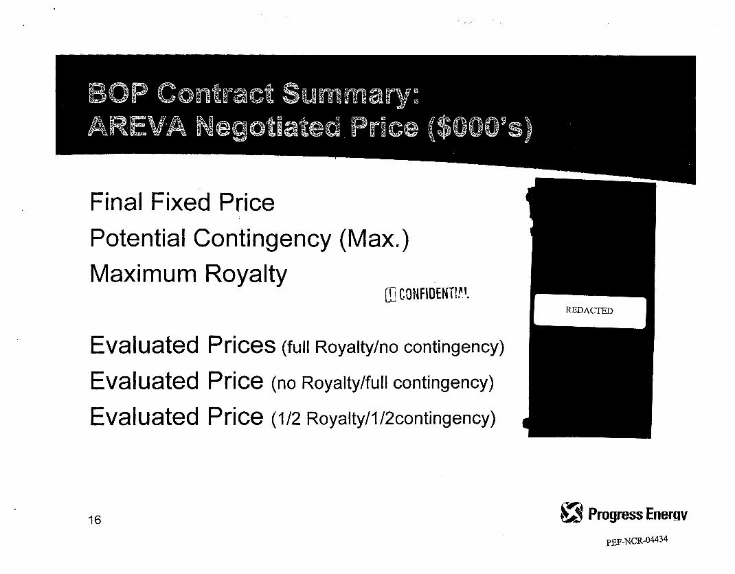
Final Fixed Price Potential Contingency (Max.) Maximum Royalty
Evaluated Prices (full Royalty/no contingency)
Evaluated Price (no Royaltylfull contingency)
Eva I u ated P rice (I /Z Royalty/l/2contingency)
16

5 Tech n ical AREVA has a proven track record with Progress for this work
-
3€Nl i‘. ’- Commercial (li , . t l ’
Proaress has ultimate control of Contingency Funding and should be
--4 -- -
Conclusion AREVA is best from a Technical perspective and on average equal
- cost with opportunity- -
17

Payment Milestones are designed to provide an incentive to complete scheduled work on time and a disincentive for failure to meet schedule.
18 -3 c- ProgressEnergy
PEF-NCR-04436

19 tr, $1 "(? ProaressEnergy
PEF-NCR-0443 7

Project Manager Ted Williams Project Technical Lead Scott Deahna Legal Dave Conley Audit Loyd Graves Contracts Lead Tony Owen Executive Sponsor Danny Roderick
20

Siemens Contract #I45569
Executive Summary Work Authorization #50
' August 8,2007
Turbine Generator Retrofit Purchase & installation
Progress Energy
1
PEF-NCR-044 3 9

iemens Contract Summary:
ontents: D
D
D
D
D
D
D
D
D
D
D
D
D
D
Scope
Schedule
Comparison of Bid Price
Negotiated Savings , Comparison of BNP Pricing
System Bundling
Performance Incentives
Warranty
Liquidated Damages/Dis-Incentive
Limits of Liability/Extension of Insurance
2009 Performance Guarantee
201 I Performance Guarantee I00 Day Performance Guarantee
Project Review Team

Siemens Contract Summary: Scope of Work
Contractor shall provide all labor, supervision, materials, equipment, and tools to supply, replace and install the High Pressure Turbine Rotors, Low Pressure Turbine Rotors, Generator, and Exciter at Crystal River Unit #3.
&,$j Progress Energy PEF-NCR-0444 1

iemens C roiect Sch
ontra edule
ct Summary:
Siemens has a 63 day clearance window for the 2009 refueling outage scope of work and a 24 day clearance window for the 201 I refueling outage scope of work. The Project Schedule consists of three distinct schedules:
+ Engineering Deliverable Schedule + Manufacturing Schedule + Installation Schedule
All three shall be submitted for owner review and approval within 60 days of contract award.
L3 rr) ProQress Energy
PEF-NCR-04442

Siemens Contract Summary: Comparison of Pricing from Bid Submittals ($000’~)
Equipment Prices Als t om Siemens
HP & LP Turbines
Gene rat0 r
Exciter
Field Installation
otal Cost
L 4 c? Progress Energy

Siemens Contract Summary: Negotiated Savings ($000’~)
iscounts Alstom Siemens
Price with Labor
Bundled Discount
Price after Discount
Evaluated Added Scope REDACTED
REDACTED B HP turbine gland steam spillover valve B Machining steam lead inlet flanges B Rotor lifting beam B Extended warranty B Extended property insurance
Total Evaluated Price
II: ~ONFIDENTI!!. b,! C- Progress Energy PEF-NCR-04444

Siemens Contract Summary: Corporate Bundling- I I Rotors

Siemens Contract Summary: Performance Incentives ($000’~)
Safety and Human Performance I nciden ts Bonus Rev. at Risk
Industrial - OSHA
Lost Time Accidents
Human Performance Index
REDACTED
PEF-NCR-04446

mm
ri E S
cn m t U
s
0

31
PEF-NCR-04448

E CONFIDENTIf,!. Y

PEF-NCR-0445 1

Siemens Contract Summary: I 00 Day Performance Guarantee
For I00 days of Continuous Operation Contractor places -at risk for each outage (2009, 201 I)
D The 100 day period begins after completion of commissioning and Unit has reached 100% power
based on the Contractor's Instruction Manual D The unit must be removed from services
fi CONFIDENTIF.!
PEF-NCR-04452

mary:
c \ Proares Energy b PEF-NCR-04453

Discounts AIstom Siemens
Price with Labor
lundled Discount
Price after Discount
ba I uate d Added Scope B HP turbine gland steam spillover val B Machining steam lead inlet flanges D Rotor lifting beam D Extended warranty B Extended property insurance
I Total Evaluated Price
,ve
Progress Energy PEF-NCR-04454

OPC
ST 1 POD
#4
080009
BATES NOS. PEF-NCR- 04455 THROUGH PEF-NCR-04470
NON-RESPONSIVE

st 1 P
#5
080009

I (in mlliions) I 2006 I 2007 I 2008 I 2009 I 2010 I 2011 I 2012 I Total I --
4. (in millions) 2006 2008 I 2009 I 2010 I 2011 I 2012 I Total
0 2008/2009 Projection 6 All major contracts now issued - Reconciling milestone payments
Increased material and labor costs Removed transmission costs Consolidated cooling tower costs with EPU
Future Years Reflecting known milestones and increased labor costs
* POD cost increases due to circulating water flow rates
Confidential
PEF-NCR-0447 1

Confidential 0 POG activity forecasted to be managed by NGG/EPU 'L _ I - -- :-. _ -
0 Studies indicate Transmission work may not be required
PEF-NCR-04472

r, - #b ~ Contract Studies for NSSS & BOP delayed past 2nd quarter, 2007
2007 Actual YTD Spend vs. YE Projection
Turbine Milestone Payments 0 Equipment Orders (MSRs, FWHEs, etc.)
Engineering Analysis .. UR YTD Spend Confidential
I -- REDACTED 2008 Over-run of&.,-,,F
Turbine Generator Bid Higher than Feasibility Study REDACTED
-..-- * Studies - indicate Transmission work may not be required(lP; e
bJj tv Progress Energy
PEF-NCR-04473

c
I
gjtPrOgreSSEnergy
Crvstal River Unit 3 Extended Power Uprate
In-Service Date 3 Actual 50'0 v December 201 1 Q)
1
I
Project L I I I
Q) Authorization Plan I 2o06 15% Fa1!07: Fa11'09: Fall'l 1 :
v) 11MW 25MW 126MW 0 Outage Add Outage Add Outage Add
As of Oct '07
* Measurement Uncertainty Recapture (MUR) Installation during Fall 2007 Refueling Outage - adds 11 MW
- Power Uprate Installation during Fall 2009 Outage - adds 25MW - Power Uprate Installation during Fall 201 1 Outage - adds 126MW -
a
Perform plant modifications that will provide Crystal River Unit 3 with the capability of producing an additional net 162 MW.
n 1 2007 Capital Spend Total Project Cost by Year
t > 0 0 6 2007 2008 2009 2010 2011 2012 Total
-'<? I -Budget -Actual A Projection 1%-
REDACTED
1 - Project costs on target
Confidential
REDACTED
Required Third Party Approvals Iss u ell m pact issue hRact/ACtiOn
finalized through early 2008 Cost management * Firm price contracts for components being
* Contingency funding available for labor and materials price uncertainty
- Seek recovery under the Nuclear Cost Recovery Rule (filing in March. 2008)
* Cost recovery

-
As of Dec '07 QPmgressEnWgy CGNFI ~ E ~ ~ l A~
In-Service Date T7 2% December 201 1 Q)
J 'c3 Project 1 I 1 I
2006 F& ;:;O FaI!J9: Fall'l 1 : 0 Outage Add Outage Add Outage Add v) 11w 25MW 126MW
I
- Authorization
Crystal River Unit 3 Extended Power Uprate Perform plant modifications that will provide Crystal River Unit 3 with the capability of producing an additional net 162 MW.
Measurement Uncertainty Recapture (MUR) Installation durlng Fall 2007 Refueling Outage - adds 11 MW; to be implemented Jan 2008 Power Uprate Installation during Fall 2009 Outage - adds 25MW - Power Uprate Installation during Fall 201 1 Outage - adds 126MW
I- 1
w 0 (0
- E \
# # I
2007 Capital Spend Total Project Cost by Year
issue ImDactl Action
Cost management - Firm price contracts for components being finalized through early 2008
Contingency funding available for labor and materials price uncertainty
Seek recovery under the Nuclear Cost Recovery Rule (filing in March, 2008) - cost recovery
PEF-NCR-04475
c;' 1, 1
- Budget -Actual A Projection ]
-2006 2OQ7 2098 2009 2010 2011 2012 Total IC-, __r
-> +Tb--
REDACTED
Milestone Cost History (16 millions) ' I Initial estimate (Dec '06)
Project to Date
* Total Project costs on target i Confidential
I I
..

0 st I P
C 0
#6
080009

0 st I P
C 0
#7
080009

BprogressEnergy Crystal River Unit 3
Extended Power Uprate
MASTER NUMBER: 20058849
Sponsor, VP - NPC Major Projects Manager, EPU EPU Engineering Superintendant, EPU Implementation
Crystal River Unit 3
Danny Roderick 240-4800 Steve Huntington 240-4752 Ted Williams 240-4356 TBD
Extended Power Uprate
Superintendan t
Proiect Financial Controls Regulatory
Integrated Project Plan
Dave Varner 240-4983 Term Hobbs 240-4746
MASTER NUMBER: 20058849
Page 1 of 27
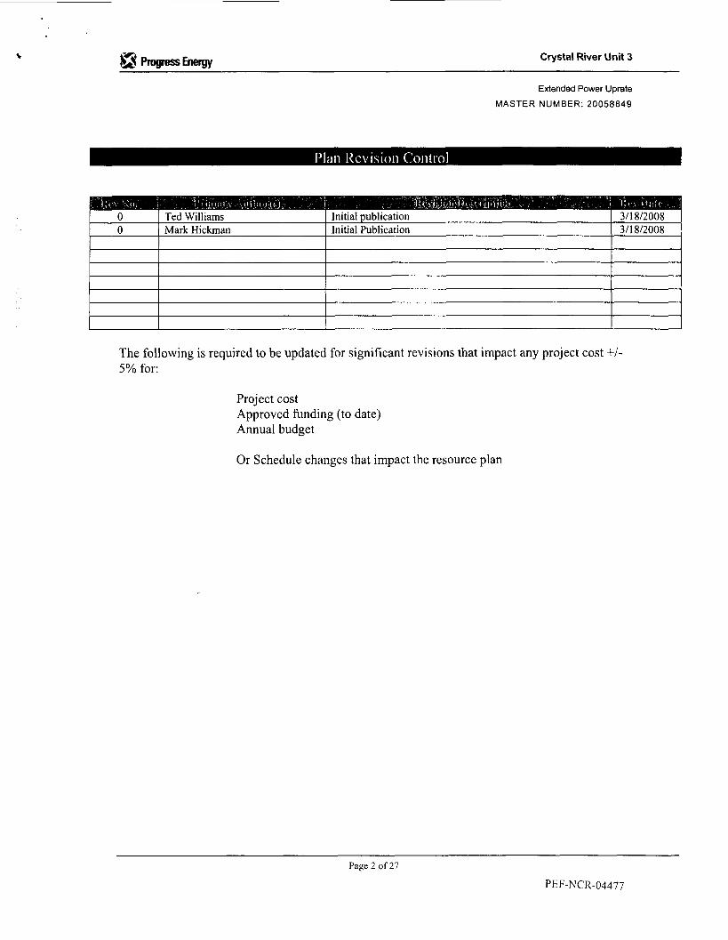
Crystal River Unit 3
Extended Power Uprate
MASTER NUMBER: 20058849
BprogessEnergY
0 0
Ted Williams Initial publication 311 812008 Mark Hickman Initial Publication 311 812008
The following is required to be updated for significant revisions that impact any project cost +/- 5% for:
Project cost Approved funding (to date) Annual budget
Or Schedule changes that impact the resource plan
Page 2 of 27
PEIF-NCR-04477

“=Energy Crystal River Unit 3
Extended Power Uprate
MASTER NUMBER: 20058849
This section contains formal sign-offs for both review & approval of the IPP. “Reviewing” applies to any party reviewing the IPP for accuracy & clarity, while “Approving” applies to those parties responsible for approving project milestone progression & funding.
T. Williams Superintendant, EPU 1 Engineering 1 oo/oo/oo
D. Vamer Manager, Major Projects Support Manager, Major
T. I lobbs Projects Project Controls
Director Site Operations CR3 J. Franke
B. Cumbie Crystal River Plant Manager- Fossil I
D. Roderick VP, Nuclear Projects & Construction
oo/oo/oo VP, Treasurer & CRO
Sr. VP Energy Delivery Carolinas
Tom Sullivan
Jeff Corbett
Sr. VP Energy Delivery Florida I Michael Lewis
Jeff Lyash President and CEO, PGN Florida I
Lloyd Yeats President & CEO PGN Carolinas Sr. VP Corporate
Counsel John McArthur Relations &General
Mark Mulhem Sr. VP Finance
Paula Sims I Sr. VP Power
PEF-NCR-04478 Page 3 of 27

Crystal River Unit 3 aprogessEnergy
Jim Scarola
Peter Scott
William Johnson
Sr. VP & CNO
President &CEO Service Co., CFO PGN Chairman, CEO, and President PGN
Page 4 of 27 PEF-NCR-04479

Extended Power Uprate
MASTER NUMBER: 20058849
1 .o Project Overview / Recommendation
2.0 Scope Statement
3 .O Major Deliverables & Milestone Schedule
4.0 Funding Requirements & Update
5.0 Economic Evaluation
6.0 Assumptions & Constraints 6.1 Risk Strategy 6.2 Contracting & Procurement Strategy 6.3 Regulatory Strategy 6.4 Quality Plan 6.5 Safety Plan 6.6 Environmental Plan
7.0
8.0
9.0
10.0
External Stakeholders
Internal Stakeholders
Project Assurance Plan
Communication Plan / Next Steps
APPENDIX:
Definitions & Acronyms
.
OPC 1 st POD
#7
080009
BATES NOS. PEF-NCR 0448 1 THROUGH PEF-NCR-0450 1
REDACTED

Crystal River Unit 3
Definitions & Acronyms:
of SGR project team members,
ingress and egress of radiation workers required to enter the containment building (also known as the reactor building) to accomplish work.
to provide details on specific tasks required to support the overall project to replace the steam generators.
provides the technical and administrative controls to ensure modifications made the nuclear facility are compliant with all applicable Progress Energy requirements and the Code of Federal Regulations for nuclear facilities. EPU: Extended Power Uprate -An increase in developed reactor power and electrical output derived from a combination of steam efficiencies, margin harvest, and reactor power increase.
ensure activities are controlled within environmental standards.
oversight and support to commercial nuclear power stations.
required to remain operable for operation of the reactor in all modes of operation.
specific parameters key to the project success are measured and used by management to take corrective actions when these parameters are not s expected.
AIMS: Action Item Management System - A database developed to track internal action items
CAF: Containment Access Facility - The structure or area specifically designed to regulate the
DTP: Detailed Task Plans - Specific plans (modeled after project plans) taken to the task level
EC: Engineering Change - A formal document developed by design engineering personnel that
ERP: Environmental Resource Permit - A permitting process required by state regulations to
INPO: Institute of Nuclear Power Operations - The organization specifically formed to provide
ITS: Improved Technical Specifications - The licensing document that outlines the equipment
KPI: Key Performance Indicators - visual indicators that are used to provide insights that
NBC: Net Benefit to Cost Ratio NRC: Nuclear Regulatory Commission - The regulatory body that oversees safe operation of
commercial nuclear facilities. NSOC: Nuclear Security Operations Center - The structure that serves as the entry point and
exit point for entry into the CR3 protected area. OTSG/OTSG's: once through steam generators- heat exchangers designed to transfer heat
from the reactor coolant system into steam used to drive the steam turbine in the generation of electricity.
performed on the nuclear facility or components fabricated in support of operation of the nuclear facility meet the established requirements for quality.
RB: reactor building - one of three designed fission product barriers designed to protect the health and safety of the public from the release of reactor coolant system inventory during a postulated emergency.
QA: Quality Assurance - A specific function internal to the project, designed to ensure activities
SGR: Steam Generator Replacement - The acronym used to describe the project. WBS: Work Breakdown Structure - The fundamental building block that defines the scope of
the steam generator replacement project
~~
Pagc 27 of 27 PEF-NCK-04502
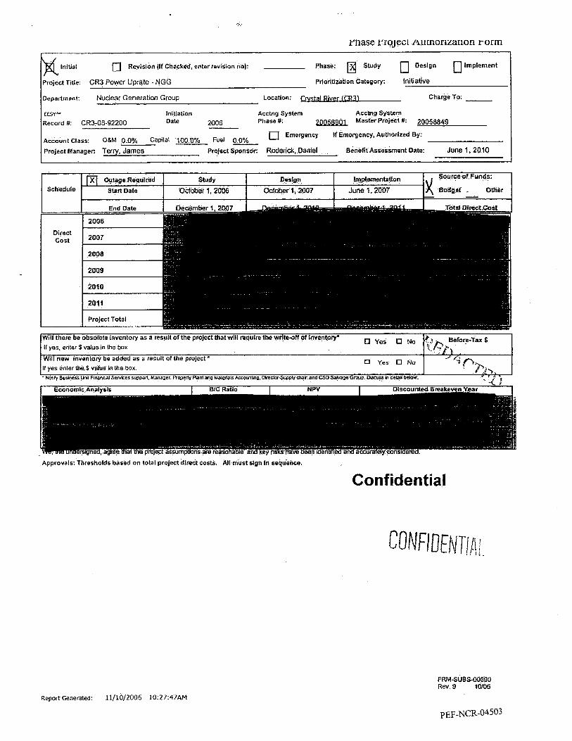
rnase rroject mxnoruation r orm
Will there be obsolete inventory as a result ofthe project thatwlll require the wrlresff of hverltory'
Will new inventory be added as a result of the project' I f yes enter UW S value in Ihe box
0 yes 0 N~
0 Yes 0 N o
If yes, enter S value in h e box
Initial 0 Revislon (If Checked, enter revision no): Phase: a Study 0 Deslgn 0 Implement
priorttizatlon Category: Initia!ive
Department: Nuclear Generation Group Location: Charge To:
6efore-f;UrS <. -'pS
' dp' opj,
lnltiatlon Acctng System Acclng System E E W U Record #: CR3-06-92200 Dale 2006 Phase #: 20058901 Master Projecl #: 20058849
AccountClass: OgM 0.0% Capilal 100.0% Fuel 00% Project Manager: Terry, James Project Sponsor: Raden'ck, Daniel
Emergency If Emergency, Authorized By:
Benefit Assessment Date: June 1,2010
I Source of Funds: Outage Requlred Study Design Imp1,ementati on
Schedule Start Date I October I, 2006 I octaber 1,2007 I June 1, 'LOOT lg BaageI ~ Other I
Approvals: Thresholds based on total project dlrect costs. All must slgn In sequence.
Confidential
C 0 NFI DEN Ti A 1
FRMSUBSoO690 RW.9 16/05
Report Generated: 11/10/2006 10:27:47AM

I

raase rrujwr fiuuiomatwn rorni
Executive Summary:
Project Basic Information:
This Power Uprate Project will add 180 MWe of net generation output io the Crystal River Nuclear Plant
Rammendation and High Level DkcUSion:
A two phase approach will be usitd for this project for steam efficiencies and reactor power uprate for a total
Funding Requirements and Source:
initiative capital project POG and Transmission PPA's will be routed for d Transmisslan costs are not ineluded in this NGG PPA The
addtessed in the Business Analysis Package. Proied C a D b l Allocation Metric Summaw Tabte:
/ + / Confidential , .,,' 'd
Cash Flow Graph:
',\ % / See attached Ecanomic Analysis Report. I- % ... *.* '
fl ". I" f '\)
Strategic Fit (if applicable): >
uclear base load generation plant and a reactor power uprate will achieve increased net power of 180,MWe realizing the economical benBfits of nuclear fuel. This power Uprat6 includes net generaation
increases of 40 MWe for steam efficiencies without fuel costkieases.
Key Risk Analysis:
~- Key Assumptions:
See Business Analysis Package
Confidential
F R M - ~ U B S - ~ I X ~ ~ O Rev, 9 10705
Report Generated: 11/10/2006 10:27:47AM

Project Alternatives Analysis:
Alternatives Considered and Basis of Selection: See Business Analysis Package
Consequences of Non-Authorization or Deferral:
Failure to realize the projected fuel savings and benefits associated with avoided capacity in part if deferred or entirely if not authorized.
Economic Analysis Detail:
Detailed Discussion of Results!
See Business Analysis Package
Scenario Analysis:
See Business Analysis Package
Summary of Financial Indicators:
See 6usiness Analysis Package
Major NPV Components:
See Business Analysis Package
Modeling Tool Used 1 Description of Changes / Approval:
EESY+ Version 5.8.2
Sensitivity Analysis Detail:
See Business Analysis Package
Regulatory Impact Analysis:
Implementation of Phase I and I1 will require FSAR and Tech Spec changes to our existing license. The study will provide for developing a regulatory approval plan.
Contracting and Procurement Strategy:
Change in Inventory Detail (either increasing due to new inventory needs or decreasing due to obsolescence):
Market Analysis:
Customer Analysis:
N/A
Competitor Analysis:
NIA
F RM-SUBS-00690 Rev. 9 10/05
Report Generated: 11/10/2006 !.0:27:47AM
PEF-NCR-04506

Non-Financial Consideratians / Intangibles / Unquantified Financial Considerations / Other:
Co-owner participation may be an option for this project. This option will be pursued independently of this PA.
Integration and Project Performance Assessment Planning:
Organizational Requirements / Integration Issues:
This project will require support from plant Engineering, Licensing, Maintenance, Operations, Chemistry, and plant management. Support from off-site organizations will include NGG Engineering, NGG Fuels, Transmission, Fossil Engineering, and Corp. Strategic Planning. A temporary project team is in place for this project pending apprpoval of the permenant organization and wilt include representation from each key organization.
Project Objectives Goals / Expected Benefits:
The project objective and goals are to effectively implement a power uprate strategy to increase the net generation from the Crystal River Nuclear Plant by 180MWe. This strategy provides the least cost alternative for this added net generation in Florida within the strategic generation plan.
Benefit Assessment Methodology, Schedule and Responsibility for Assessment:
Procurement and installation for)he power uprate project will provide for increased net generatian of 180 MWe from the Crystal River Nuclear Plant. The project will be completed by December 201 1. The project manager will be responsible for the benefits assessment upon completion of each phase.
Resoonslbllitv for Assewn ent: Williams, Ted E.
Wrap-up Conclusions and Recommendations (Pros lk Cons):
The recommendation is to proceed with planning and implementation of Phase I and I I for this project. This is based on the strategic fit for increased net generation in Florida and the steam efficiencieslnuclear fuel least cost alternative to provide 180 MWe of additional net generation. A decision to not implement this project will result in a lost opportunlty for increasing net generation of 180 MWe using the nuclear least cost alternative for steam eficiencies and nuclear fuel. Appendix A: Pro Forma Economic Analysis:
Appendix 8: Pro Forma Financial Sbtemmts:
Other Appendices:
i: 0 N F t U EN TI Ah.
FRM-SUES40690 Rev. 9 10105
Report Generated: 11/10/2006 10:27:47AM
PEF-NCR-04507

Previous Phase Cost Status - Project View Costs
Variance Exolanatlon (if variance outside target range**): I/:>\ ;J -(<*% '
> 'c' . * Use Projections 3 of PRG revlew data, if phase k not dosed out ,y > ** Vanance for any Phase +/- 10% arid greater than $20,000. ?, _.*
Confidential
Previous Phase Schedule Status - Project View Costs
Report Gecterated: 11/10/2006 10:27:47AM
~ O ~ F REN
Sponsoring Business Unit:
Funding Legal Entity:
Date Prepared:
IAi
NGG - CR3
PEF
1 1-1 0-06
Progress Energy Florida
CR3 Power Uprate
Business Analysis Package
Role, DepartmenVGroup Sponsor - CR3 - NGG Financial - CR3 - NGG Engineering - CR3 - NQG Project Manager-CR3-
Name Phone # Danny Rodericlj, - 240-321 9 Dan Taylor Ff-,.. / I - /# - 4 240-31 65 Ted Williams ' 240-3886 Jim Terry 240-4321
NGG

. .
. ............. ... . . . . . . . . . . . .
Table of Contents Executive Summary ................................................................................................................... 1 Strategic Fir ................................................................................................................................. 3 Key Risk Analysis ....................................................................................................................... 3
Key Assump fions ....................................................................................................................... 4
Project Alternative Analysis ..................................................................................................... 5 Economic Analysis .................................................................................................................... 5 Sensrtivrty Analysis Detail ......................................................................................................... 8
Operational Analysis Detail .......................................................................................................
Contracting and Procurement Strategy .................................................................................. 9
. . .
Regulatory Impact Analysis ...................................................................................................... 9
Change in Inventory Detail ........................................................................................................ 9
Market Analysis ........................................................................................................................ 10
Non- Finan cia I Con sidera tiond In tangibled Wnquan ti fied Financial Considerations / Other ........................................................................................................................................... 10
Integration and Project Performance Assessment .............................................................. IO Wrap-up, Conclusions and Recommendations ................................................................... 10 Appendix A: Pro Forma Economic Analysis ........................................................................ 11
Other Appendices ..................................................................................................................... 11
PEF-NCR-045 10

CON FI D ENTI AL Execu the Summary
Project Basic information Description: This Power Uprate Project will add 180 MWe of net generation output to the Crystal River Nuclear Plant
Location: Crystal River Unit 3
EESY Plus Project#: Record # CR3-06-92200 - Master Project # 20058849
Schedule: October 2006 - December 201 1
Recommendation and High Level Discussion
A two phase approach will
additional net generation reactor power from 2,568
grid modifications to accommodate distribution of the added 180 MWe output a being the largest generator in Florida
The recommendation is to proceed wi is based on the strategic fit for reduct/ least cost alternative to provide 180 MWe of additional net generation with this project also addresses the Point of Discharge temperature issues that between proposed fuel adjustment clause and the environmental recovery Economic Anatysis are for th 3 total project cost.
ning and implemen otal fuel costs in FI
Funding Requirements and Source
ns (PPA). NGG-CR3 million. POG will Transmission will
ion. When fhe PPA‘s cument. This Strategy
will do a PPA for
submit a PPA for
departments. The Progress Energy project management organization will have representation from POG and Transmission to coordinate and provide oversight to their work scope‘s.
Page 1 of 16
PEF-NCR-045 1 1

CU NFI DEI? f l A f_
This is the 3-Phase cash flow by department:
Direct Cost in $000 '~
- 2006 2001 2008 2009 2014 2611
si:'
lion study phase will provide the plant specific projkct plan. Water cooling and transmis ill be covered u
project schedule, task cost review. The study will also procurement strategy along Wifh needed con include a detailed review of "pinkh points" to
Project Capital AIIoca
ose individual studies. This plan will include development of a d tes, equipment specifications, license amendment plan, and permit
the needed technical in
Metric Summary Table s enarios: Recommended Alternative
(OBEY) I Operational / Other Metrics I
Confidential
Page 2 of 16
PEF-NCR-045 12

Cash flo w Graph
Cumulative NPV By Year flOOo)
Strategic Fit r CR3 is a nuclear base
production of 18 effective way to
plant and a reactor power uprate ost power uprate prov
Page 3 of 16 Confidential
Key Assumptions
These numbers are the same for base and best case scenarios. For worst case scenario capital costs are increased by 10%.
Escalated Cooling and Transmission Upgrade costs ate as follows for best case, base case and worst case scenarios:
Page 4 of 16 Confidential

0 N FI 0 EN TI A t * P t
--- Page 5 of I S Confidential
PEF-NCR-045 15

Scenario Analysis
case la
Summary of Financial Indicators
REDACTED
Confidentia

CONFl ~ENTIAL
Maior NPV Components (based on July GFfl
Modeling Tool k e d / Description of Changed Approval
EESY+ Version 5.8.2 Confidential
Page 7 of 16
PEF-NCR-045 17

Sen sit i vit y Ana I ysis Detai I
CONF IDEN TI A l
Confidential
Page 8 of 16

CON F f DEN VIAL ODerational Analvsis Detail
on the exfensive fuel the grounds that the result in a lower cost
the public welfare”.
PEF further requested recovery of the pro e ro the fact that this project generate for the customer
ast base rate proceeding. A 2007, and the Commission d
recovery through t h e fuel clause, the Company will i
PEF will also be required to submit
uel clause can be
R3 Uprate. The process for amending commercial nuclear power plant licenses sltions related to power uprates is the same as the process used for other
amendments; therefore, power uprare requests are submitted to the NRC as license amendment requests. The NRC has approved many similar uprate requests and PEF expects approval of our application.
The study will provide for devefoplng a regulatory approval plan.
~
Change in lnventorv Detail
Page 9 of 16
PEF-NCR-045 19

Market Analysis N/A
Intangibles/ Unquantified Financial
Wrap-up, Cohclusio~s and Recommendations
Confidential
Page 10 of 16
PEF-NCR-04520

Appendix A: Pro Forma Economic Analysis
Page 11 of 16

@ hew EESY-Plus Project Analysis Report Record D: 93980 I Altemdiva No: ~lEmacted~Case
DOl(WIUbNa4 hdukd
I REDACTED
Confidential
Page 12of 16

Oocument title
Major Capital Projects - Integrated Project Plan
AOM-SUBS-00080 Rev. 0 (01108)
Oocument number
ADM-S UBS-00080
Applies to Progress Energy Carolinas, Inc.; Progress Energy Florida, Inc.; Progress Energy Service Company, LLC
_ _ Page 1 of a.
Keywords. administration; major projects; capital budget
1.0 APPLICABILITY Energy operating companies and business units conducting non-routine,
project costs, referred to as ‘Major Capital Projects’ O r ‘Major Projects’. projects within the Company (e.g., new generation,
environmental programs, associated transmission, etc.).
2.0 PURPOSE The purpose of this procedure is to govern the overall process flow and expectations for managing Major Projects. Each impacted operating company / business unit is required to integrate their respective project plans and business case analyses for fUnding approval at each major milestone throughout the project I i fecycle.
3.0 GENERAL INFORMATION This procedure is the governing document for authorizing Major Projects and is referenced in procedures ACT-SlJBS-00335, Progress Energy Project Governance Policy, and ACT-SUBS-0026 I , Project Evaluation and Authorization. Each organization managing Major Projects is required to develop and maintain procedures for implementing this procedure.
Initial funding approval is granted by presentation to the Senior Management Committee (SMC). Subsequent funding approval is granted at each major milestone throughout the project lifecycle by presentation to the appropriate member of senior management and other constituents. ‘The communication tool used to request authorization and obtain approval signatures is the Integrated Project Plan (Ipf‘).
4.0 INTEGRATED PROJECT PLAN (IFP) Major Projects can involve multiple operating companies / business units, each developing their own specific project plan (Appendis No. 1). Major Projects require the integration of project plans and information to summarize key touch points (bpendix No. 2). The IPP takes the place of the Business Analysis Package (BAP), but contains similar BAP elements referenced in procedure, ACT-SlJf3S-0027 I , Progress Energy Business Analysis Package.
The IPP is used to: Guide the Project Execution for all impacted operating companies / business units Provide an executive su”ary of each business unit-specific project plaii Document project assumptions, constraints, and decisions
Define review and funding approval milestones Provide a baseline for progress measurement and project control Integrate other sub-plans developed to manage and identify the following:
’ Facilitate communication among stakeholders ’
o Project scope o Major deliverables & milestone schedule
CONFl DENTlA L

AUTHORIZED COPY
ADM-SUBS-00080
0
0
0
0
0
0
0
0
0
0
0 0
0
0
Rev 0 ( O l / O 8 ) I Page 2 of 8
Funding requirements Economic evaluations Assumptions and constraints Risk strategy Contracting / procurement strategy gi supplier diversity Regulatory requirements External stakeholders requirements Internal stakeholders roles & responsibilitics Resource allocation Project assurance Startup and integration Safety & environmental Communication planning Others, as determined by the project
4.1 IPP Development Thc IPP i s summarized using a template available by contacting Capital Planning & Control.
T h e business unit selects a coordinator to be the point contact to develop the IPP; The IPP Ocvelopment Coordinator’s role is to ensure timely submission of each IPP section and collaborates with Capital Planning & Control to schedule the funding approval meetings. The Coordinator sclicdules an IPP kick-off meeting with the project team and assigns sections (APpcndis No. 3) .
U p o n receipt of each written section, thc Coordinator assembles the IPP and submits internally for review and comment. Internal review meetings help to collaborate and expedite the review process, The section writers are responsible to ensure the accuracy and completeness of each section.
NOTE: During Project Initiation, elements of the IPP may not be fully identified. The expectation is that all IPP elements are completely identified and updated throughout the project lifecycle. The initial IPP for the first milestone is to provide adcquate information to justify the funding amount requested.
5.0 PROJECT AUTHORIZATION Project Authorization is governed by the procedure, AC l--SIIUS-00261, Project Evaluation and Authorization. Major I’rojects require funding approval obtained by presentation to the SMC prior to any spending. The IPP and high-lcvcl presentation are the tools used to communicate the milestone funding requests.
5.1 Project Review Group (PRG) Approval ‘l’hc project manager presents the IPP to the corresponding Project Review Group (PRG) for project cvnluation and authorization, as applicable. During this meeting, the PRG reviews the IPP i ti formation, obtains clarification, and approves the project to be submitted for funding approval.
5.2 Senior Management Committee (SMC) Approval Once q ~ p r o v e d by the PRG, the project manager submits thc [PI’ to Capital Planning gi Control for review and submittal to the SMC. Capital Planning & Control will schedule th? SMC presentation.
The project manager and/or sponsor formally present the initial IPP to the SMC. ‘I’he objective of this presentation is to obtain project authorization and funding approval for the first major milestone in the project I i fecycle.
PEF-NCR-04526

AUTHORIZED COPY
I’rior to work beginning for the second and subsequent milestones, the IPP is updated and presented to appropriate members of senior management and other constituents for review and approval. 7 his presentation outlines progress to-date and requests additional funding. This step is repeated throughout the project lifecycle for each major milestone.
5.3 Board of Directors Approval Once approved by the SMC, Capital Planning & Control will coordinate a presentation for final approval to the Board of Directors. The presentation contents, timeframe, and presenters will be detennined in coordination with Capital Planning & Control.
6.0 PROJECT MONITORING & CONTROL The project manager and/or sponsor will present quarterly SMC updates reviewing status on all Major Projects. Capital Planning & Control will schedule and facilitate these review sessions.
Project Authorization Revision (PAR) requirements are detailed in Section 9 of procedure ACT-SUBS-0036 I , Project Evaluation and Authorization.
The expectation is each operating company / business unit involved-with a Major Project develops appropriate monitoring systems ensuring identified project standards are being met, and appropriate corrective action is completed. Capital Planning & Control will facilitate communication betwecn business units, operating company finance committees, the SMC, and Board of Directors, as needed.
7.0 PROJECT CLOSURE Project Closure confirms acceptance of project deliverables by the Sponsor organization. For example, acceptance includes functional testing, punchlist item management, turnover, and financial closeout.
Major I’rojccts require the completion of a Post Project Benefits Assessment (PPBA) as identified in Section 1 1 of procedure &J-SCJHS-0026 I , Project Evaluation and Authorization. The project manager and/or sponsor will present the PPBA to the SMC to determine whether the Company realized its intended benefits.
8.0 REFERENCES ACT- S I J I 3 S -00 3 3 5 - ACT-SIJ13S-00261 - ACT-SlJl3S-0027 I - ADM-SUI3S-OOIO5 - ._ - -_-.___ ADM-CAI’X-0000 I - A [>M -TI< M X -00003 - CON-I’PI>X-0000 I - ___.____ N(i(;M-I’M-0018 -
Progress Energy Project Governance Pol icy Project Evaluation and Authorization Progress Energy Business Analysis Package Project Assurance Program Policy Project Assurance Program Manual Transmission Department Project Management Procedure Execution of Large Construction Projects and Programs NGG Project Management Program Manual
I ADM-SUBS-00080 I Rev. 0 (01108) I. Page 3 of 8 1
PEF-NCR-04527

AUTHORIZED COPY
ADM-SUBS-00080
APPENDIX NO. 1 - Eicmcrits of a Project Plan
Rev. 0 (01108) Page 4 of 8
Business unit-specilic project plans contain, but are not limited to, the following elements. At thc beginning o f the project, sonic elements are riot clearly defined. The expectation i s during Project Planning; these elernents are completed and continually updated during the project lifecycle.
Objectives - The goals o f the project identified as realistic, specific, measurable, time driven, and cost driven. Objectives at a minimum address safety, cost, schedule, and performance; defining success for the project.
Scope - Clear definition of the work required and documented boundaries o f the project consistent with objectives, including applicable specifications and standards. It i s important for the Project Team, Project Sponsor, and key Stakeholders to understand and agree on the scope to minimize future misunderstandings.
Deliverables - Tangible and verifiable tasks, actions, or items required to prove progress towards the objectives. These are also high-level milestones and elenicnts developed from the Work Breakdown Structure.
Work Rreakdown Structure (WBS) - A WBS i s a deliverable o f the project that organizes and defines project activities to complete the entire project scope. The breakdown o f larger tasks into smaller ones.
Schedule - The planned dates for performing activities and meeting niilestones. Activity durations and predecessors assist in preparing
Budget & Cash Flow- The estimated costs for resources identified for the project with anticipated timeframe the costs wil l incur.
Assumptions and Constraints - Known assumptions or constraints that may impact project success. Constraints may be controllable or uncontrollable factors, resources, and conditions which restrict the team’s approach. An example is environmental compliance dates.
Stakeholders - Any individual, group, organization, or agency that can affect, or be affected by, the project. Examples include members of managemcnt (plant, department), senior management, employees, vendors, government leaders, media, arid general public.
Roles and Responsibilities - Roles and responsibilities o f individual Project Team members, identifying who docs what, when, and why.
Regulatory Strategy - Strategy, plan, and schedule for ensuring regulatory recovery of costs, obtaining required regulatory permits and meeting regulatory reporting requirements. Discuss regulatory implications and actions to mitigate.
Procurement Strategy Approach for obtaining major equipment / material for the project in collaboration with Supply Chain Management,
Contracting and Supplier Strategy -
Approach to segregate scope and secure resources internally or externally for engineering, procurement, construction, start-up and commissioning The strategy must follow applicable contract management procedures i n collaboration with Supply Chain Management. I t i s essential that payment be based on production performance.
Resource Plan - Internal and external resources required to execute the WBS per the proposed schedule with the proposed contracting strategy.
CO N F 1 D E NTI nl

AUTHORIZED COPY
ADM-SUBS00080
Lessons Leiirnetl Theplan for how lescons learned from prior similar projects will be incorporated into this project and the mechanism for capturing lessons leamcd on the current project.
Quality Plan - The identification of quality / technical standards and plan for Iiow performance will be evaluated on a regular basis ensuring standards are followed. This includes identification of documents and analyses for review, holdiwitness points for factory and field verification, and guidelines for quality assurance / control documentation.
Rev 0 (01108) Page 5 of 8
Safety Plan - Identification of responsibilities, contractor-specific safety requirements, medical treatment provisions, job safety analyses, inspections, training, reporting, and housekeeping.
Environmental Plan - The permitting strategy and identification of site-specific responsibilities and contractor-specific requirements.
Security Plan - Identification of security needs and how tllese needs and/or requirements will be met during the project.
Star tup and Integration Plan - Tasks, actions, responsibilities and documentation required to integrate the project into the operating organization. The integration plan addresses any interactions between projects and operating sites & the start-up and commissioning process.
Data Management Plan -
The process and infrastructure for electronic data management. This includes, but is not limited to, specification of data management tools, the document review process, records retention and management, and end deliverable transfer.
Communication and Reporting Plan - How the project team will communicate, key meetings to be held (including critical project reviews and checkpoints), and definition of the specitic performance indicators for the project. Indicators are of two types. ( I ) Leading Indicators are a project management tool for prediction and correction of issues before they impact overall project success. ( 2 ) Scorecard indicators are used to report project statw to objectives to stakeholders.
Change Management - The agreed to process for initiating, evaluating, and dispositioning significant changes to project scope, schedule, budget, or functionality. I t is important to consir er internal and external change management. Project Team members and Project Sponsor are required to read and understand the shange management process for the project.
Close-out Criteria -
Tasks, actions, expectations, and deliverables to be satisfied to complete the project. Developing a checklist prior to close-out assists in successfully closing out the project.
Project Assurance Plan Establish the methods where key stakeholders will work together ensuring key decisions made are prudent, documented, retrievable, and support the regulatory process for cost recovery. The Project Assurance organization coordinates plan development i n accordance with the Project Assurance Program Manual.

AUTHORIZED COPY
ADM-SUBS-00080 Rev. 0 (01/08) -
APPENDIX NO. 2 - Business Unit-Specific Project Plans vs. Integrated Project Plan
Page 6 of 8
Zure 1 : Example of Business Unit-Specific Project Plans
Projects can involve multiple business units. Typically, each business unit develops their own, unique project plan enabling it to execute its portion of the project. Generally, each plan identifies their project activities; however, the touch points between the other business units can sometimes be missed.
;urc 2: Integrated Project Plan
U\ A \
I
,---
Major Projects, with their inherent risks, require the need to breakdown the walls between each business unit. Once each business unit develops its own project plan, the plans are summarized and integrated into an Integrated Project Plan (IPP). The template for the IPP is available from Capital Planning & Control.
The IPP is an executive summary document used to gain approval at each major milestone (;.e., critical decision point of the project). The project team updates the IPP during the project lifecycle and presents to the SMC for on-going funding approval at each milestone as defined in the IPP.
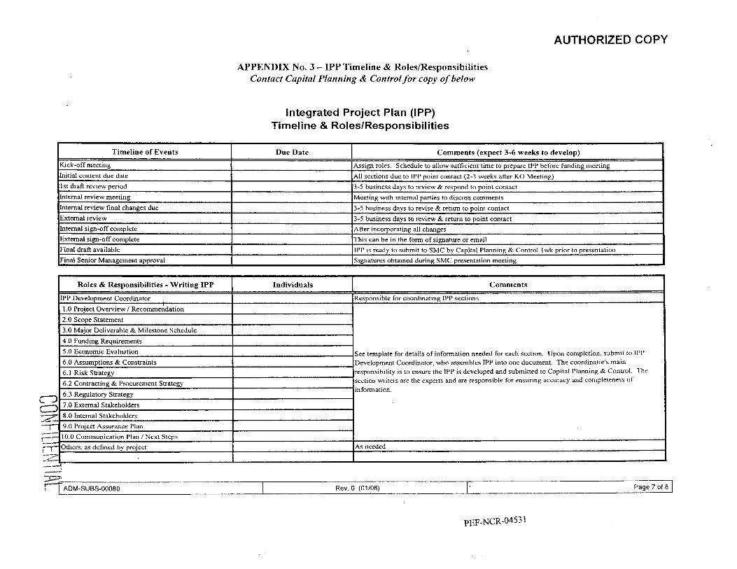
AUTHORIZED COPY
Timeline of Events
Kick-off meeting
Initial content due date
1st draft review period Internal review meeting
Intemal review final changes due External review
APPENDIX No. 3 - IPP Timeline & RoledResponsibilities Contact Capital Planning & Control for copy of below
Due Date Comments (expect 3-6 w e e k to develop)
Assign roles. Schedule to allow sufficient time to prepare LPP before funding meeting
All sections due to LPP point contact (2-3 weeks after KO Meeting) 3-5 business days to review & respond to point contact
Meeting with internal parties to discuss comments 3-5 business days to revise & retum to point contact
3-5 business days to review & r e m to point contact
Integrated Project Pian (IPP) Timeline & Roles/Responsibiiities
Internal sign-off complete External sign-off complete Final draft available Final Senior Management approval
After incorporating all changes This can be in the form of signature or email IPP is ready to submit to SMC by Capital Planning & Control 1 wk prior to presentation Signatures obtained during SMC presentation meeting
See template for details of information needed for each section. Upon completion. submit to IPP Development Coordinator, who assembles IPP into one document. The coordinator’s main responsibility is to ensure the LPP is developed and submitted to Capital Planning & Control. The section writers are the experts and are responsible for ensuring accuracy and completeness of
I I
Page 7 of 8 -7
Rev. 0 (01/08)

AUTHORIZED COPY
APPENDIX No. 3 - IPP Timeline & Roles/Responsibilities
Integrated Project Pian (IPP) Timeline & RoleslResponsibilities
I Roles & Responsibilities - Reviewers I Individuals I Title I
I
I Page 8 of 8 ADM-SUBS-00080 Rev. 0 (01108)
PEF-NCR-04532

' e
Crystal River Unit 3 Extended Power Uprate Project
Additional Cooling Capacity for the Discharge Canal
Project Plan MASTER PROJECT NUMBER: 20058849
Revision History
CONFl DENTI AL

Additional Cooling Capacity for the Discharge Canal Project Plan
Change Basis for Revision
Original Issue
Page 2 of 76
R e v 0
- CONFIDENTIAL PEF-NCR-04534

Additional Cooling Capacity for the Discharge Canal Project Plan
Executive Summary
Rev 0
Progress Energy Florida (PEF) plans to increase the electrical power output of Crystal River 3 (CR3) in order to minimize customer cost and enhance shareholder value. Currently operating at a licensed core power level of 2568 MWt and 903 MWe, PEF intends to achieve a power uprate of approximately 17% at CR3 enabling the unit to safely operate at 3014 MWt and 1080 MWe. The CR 3 modifications to allow additional electrical power generation will be implemented in three stages over the course of three refueling outages. Each modification is described below.
Measurement Uncertainty Recapture (MUR)
This project installs new more accurate and precise feedwater flow measurement equipment. The new instrumentation will enable a power increase of approximately 1.6% or 14 MWe. Existing plant safety analyses will remain unchanged as the analyzed core power will not change.
MUR implementation is scheduled for 2007, during Refueling Outage (RFO) 15.
Balance of Plant (BOP) Efficiency
The low pressure steam turbine and other BOP equipment will be replaced with more efficient equipment. The new BOP equipment will increase the thermal efficiency of the secondary side of the plant and create a potential increase in electrical power of greater than 30 MWe, with no change i n thermal power.
BOP equipment changeout is scheduled for 2009, during RFO 16.
Extended Power Uprate (EPU)
Numerous plant modifications and a significant Licensing effort will enable reactor thermal output to increase by 17% to a total power of 3014 MWt. The corresponding electrical power increase is approximately 1080 MWe. With increased electrical output, both the heat rejected by the CR3’s Circulating Water System to the discharge canal and the rate of heat carried into the discharge canal will increase. The increase in thermal energy transfer is due to the increased energy delivered to the turbines and the increased circulating water flow through the condensers to remove the additional latent heat of condensation. Without mitigation of this additional heat rejection the operation of CR 1 and CR2 may be adversely impacted or the temperature of the discharge canal may increase above permitted levels. Therefore, additional cooling capacity (e& cooling towers) will be required to remove the heat generated from the CK3 EPU.
The EPU modifications will be completed during RFO 17
Modular and Helper Cooling Towers
In order to minimize the derates of CR Units 1 or 2, due to excessive Discharge Canal water temperature, a portion of the Discharge Canal water is cooled by directing its noli. through either a Ifelper or Modular Cooling Tower. The cooled Discharge Canal water then returns to the Discharge Canal were i t mixes with other water that is flowing to the Gulf of Mexico. The I lelper Cooling Towers are permanent Crystal River I W plant systems while the Modular Cooling Towers are leased. The Modular Cooling Tower lease expires at the end of 2010.
CONFl UENTl At

Rev 0 Additional Cooling Capacity for the Discharge Canal Project Plan
Although the Modular Cooling Tower lease will expire, the need for the cooling performed by the Modular Cooling Towers remains. The logical approach to resolve the Discharge Canal cooling issue is to address both the need for additional cooling due the implementation of the Extended Power Uprate Project and the expiration of the Modular Cooling Tower lease at the same time. Therefore, this project includes the combined alternatives analysis of replacing the Modular Cooling Towers, the potential up grade o f the Helper Cooling Towers to obtain maximum efficiency, and addition of cooling capability to support the EPU Project. The Study Phase of the Additional Cooling Capacity for the Discharge Canal Project will perform the Alternatives Analysis and develop a conceptual design of the recommended alternative. The Design Phase will convert the conceptual design into a final design. Then the Implementation Phase will construct the chosen alternative.
This document is the Project Plan for the Additional Cooling Capacity for the Discharge Canal Project, hereinafter called the Plan. The Plan focuses on the identification, selection, & installation of equipment to maintain &he Discharge Canal’s point of discharge (POD) water within acceptable parameters. The Plan identifies the project management strategies, tools, techniques and instructions necessary to safely achieve the additional cooling capacity goals and objectives while minimizing the Project’s cost and risk. The project authorizations and management plans contained in this document include:
A Project Mission Statement
The Project Charter
The Project’s Scope, Schedule, Cost and Risk Management Plans
The Project’s Contract, Procurement and Quality Management Plans
Human Resource and Communication Management Plans
Safety, Human Performance and Environmental Management Plans
The Project will be monitored, controlled, and implemented using the existing Progress Energy Florida and Crystal River infrastructure of policies and procedures.
Page 4 of 44 CONFIDENTIAL

Additional Cooling Capacity for the Discharge Canal Project Plan Rev 0
Acronyms
Page 5 of 44 CONFl DENTI A1

Additional Cooling Capacity for the Discharge Canal Project Plan Rev 0
Table of Contents
Executive Summary ................................................................................................................. ......3
Acronyms ............................................................................................................................ ......5
1 .o
2.0
3.0
4.0
5.0
.............................................................. .................................. Integration Management !. ..8 1. I Introduction and Business Case ................. ............................... 8
1.2 Project lmplementati ............................................................................. 9
1.3 Project Mission & G ............................... 1.4 Project Charter ......... ......................................................................
.......................................................................................................................... I O
....................... ................................. .................................. I8
1.7 Project Deliverables .. 22
Scope Management Plan ................................................................................................. 25
I .6 Project Objectives
.............................................................................
2. I Scope Development ......... .........................
2.2 Work Breakdown Structure (WBS) ........... ..............................
2.3 WBS Dictionary ................ ........................... ...................................... 26
2.4 Scope Control Process .. ...................................
Schedule Development and Management Plan ............................................................. 28 3. I Schedule Development Planning ................ ........................................
3.2 Schedule Management .............. ............................................................................... 29
4.1 Organizational Structure .................................................... .................................... 30
4.3 Project Manager .....................................................................
......... 28
Resources Management / Staffing Plan ...........................................................................
4.2 Project Sponsor.. ........ 7 . . ..................................................................
4.4 Functional Organization - Roles and Responsibilities ...... 4.5 Staffing Plan .................... ........................................... 33
.................................. 4.6 'I'raining Qualification ...... ........................
5.1 Financial Controls ....................................................... ........................................... 34 Cost Management ............................................................................................................ 34
5.2 Project Cost Estimate
Page 6 of 44 CONFIDENTIAL PEF-NCR-04538

Additional Cooling Capacity for the Discharge Canal Project Plan
6.0
7.0
8.0
9.0
10.0
11.0
12.0
13.0
14.0
Table of Contents, continued
Rev 0
Risk Management ........................................................ :... ................................................ 35 ........................ 37 6.1 Decision Analysis .. ............................. .....................
6.2 Known Issues and Risk .................. ........................... ................................. 37
Procurement Management ............................................................................................... 38 7.1 Time & Materials Contract
................. ........................ 38 7.2 Fixed Price Contract ....... ....................
Quality Plan ............................................................................................................... .......39 39 ........................... 8.1 Quality Plan ........................... ............................
8.2 Benchmarking of Similar Projects ........... ...................... ..................... 39
8.3 Engineering Product Quality ........ ........................................................................ 40
Communication Management ......................................................................................... 40
9.1 Information Management ........................ ...................... ................................ 40
Safety Man age men t ...................................................................................................... ..A3
Human Performance Plan ........................................................................................... ....43
Environmental Management ..................................................................................... .....43
Financial Management ............................................................................................... .....43
Contract Management ................................................................................................... ..44
14.1
14.2
14.3
Appendix A
Appendix B
Appendix C
Appendix D
Appendix E
Contract Development ........................... ................. ............................. 44
44
................ 44
Incentive Basis ...................... ................. ..................................
Claim Management ... ................................................................
Appendices
Project Charter ................................................................................................ A-1
Organization Structure .................................................................................... €3- 1
Work Breakdown Structure ........................................................................... C-1
Schedule ............................................................................................................ D-1
Additional Cooling Capacity Project Personnel ............................................ E-1 Action Item Management System (AIMS) Guide for Discharge Canal
Page 7 of 44 CONFIDENTIAL PEF-NCR-04539

*
OPC 1 st POD
#7
080009
BATES NOS. PEF-NCR 04540 THROUGH PEF-NCR-046 12
REDACTED

Crystal River Unit 3 Power Uprate Project
Phase I:
Measurement Uncertainty Recapture
Project Plan
MASTER PROJECT NUMBER: 20058849
Revision History I
Project Sponsor
0 I 4127107 I Danny Roderick
Revision I Date Project Manager I I
I
I 1
I I I
1 I 10103107 avid Varner for Danny Roderick
I'BF-NCR-046 13

Change Basis for Revision
Revision 1:
1.
2.
3 .
4.
5 .
6.
7.
8.
9.
10.
I I .
Pg. 3 , Executive Summary, and throughout Project Plan: For consistency, changed 14 MWe to 12MWe per discussion with Ted Williams. This number ranged from 12 to 14 throughout the document. 12 MWe is the conservative value.
Pg. 4, Acronyms: Deleted “SCP Service Condensate Pump?” It was there with the question mark. Could find no basis to leave it there.
Pg. 5, 6, Table of Contents: Made changes so sectionhubsection names correspond with actual names in plan.
Pg. 7, 1. I , 2”d bullet: changed 26 MWe to 28 MWe per Ted Williams to be consistent and to ensure that-the total increase is 40 MWe (12 + 28).
Pg. 8, 1.2, and throughout document: Where applicable, corrected procedurehanual names and numbers to actual names and numbers.
..
Pg. 8, 1.2, 3rd bullet at top of page: Per-Ted Williams, changed classificationof MUR project from “Medium for MUR(EDACTED)’ to “Large for MU REDACTED Throughout document: Where spectfrc plans are named that will be addressea only by sections in this Project Plan, changed wording to reflect that.
Pg. 9, 1.4 Mission Statement: Per Ted Williams concurrence, to the pyramid of best practices, added “Regulatory Compliance.”
Pg. 26,4.4.3: Changed “See Section 9.0.” to “See Section 7.0 Procurement Management” to reflect correct section.
Throughout: Made many editorial and punctuation changes and corrections. Made many minor editorial changes for consistency (same wordltermlnumber used in all occurrences, etc.). Added new Section 15.0, Project Closure.
Measurement Uncertainty Recapture Project Plan
PEF-NCR-04614
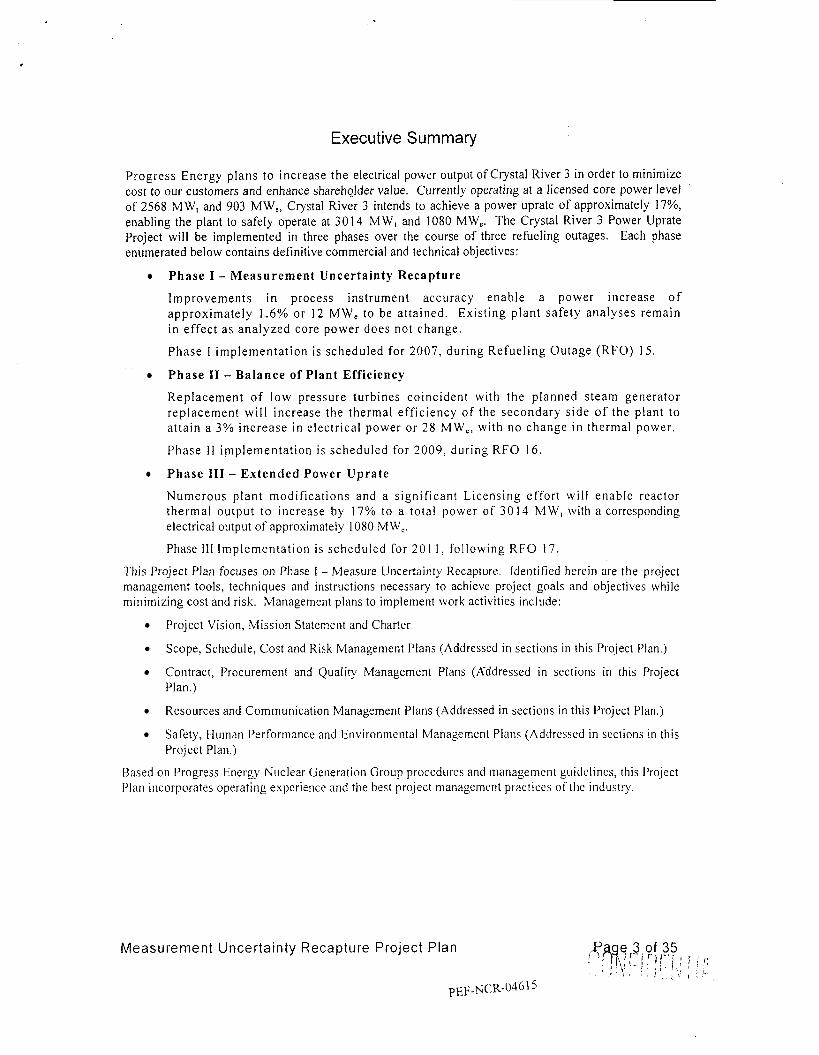
Executive Summary
Progress Energy plans to increase the electrical power output of Crystal River 3 in order to minimize cost to our customers and enhance shareholder value. Currently operating at a licensed core power level of 2568 MW, and 903 MW,, Crystal River 3 intends to achieve a power uprate of approximately 17%, enabling the plant to safely operate at 3 0 1 4 M W , and 1080 MW,. The Crystal River 3 Power Uprate Project will be implemented in three phases over the course of three refueling outages. Each phase enumerated below contains definitive commercial and technical objectives:
Phase I - Measurement Uncertainty Recapture
Improvements in process instrument accuracy enable a power increase o f approximate ly 1.6% or 12 MW, to be at ta ined. Exis t ing plant safety ana lyses remain in effect a s ana lyzed core power does not change .
P h a s e I implementa t ion is scheduled for 2007, dur ing Refue l ing Outage (RFO) 15.
Phase I1 - Balance of Plant Efficiency
Replacement o f low pressure turbines coincident with the planned s team generator replacement wil l increase the thermal eff ic iency o f the secondary s ide o f the plant t o a t ta in a 3% increase i n electrical power or 2 8 MW,, with no change in thermal power.
Phase I 1 implementa t ion is scheduled for 2009, during R F O 1 6 .
Phase 111 - Extended Power Uprate
Numerous plant modif icat ions and a s ignif icant Licensing e f for t will enable reactor thermal output to increase by 17% to a total power o f 3 0 1 4 MW, with a corresponding electrical output of approximately 1080 MW,.
Phase 111 Implementat ion is scheduled for 201 I , fo l lowing R F O 17.
This Project Plan focuses on Phase 1 - Measure Uncertainty Kecapture. Identified herein are the project management tools, techniques and instructions necessary to achieve project goals and objectives while minimizing cost and risk. Management plans to implement work activities include:
f’roject Vision, Mission Statcmcnt and Charter
Scope, Schedule, Cost and Risk Management f’lans (Addressed in sections i n this Project I’lan.)
Contract, Procurement and Quality Management Plans (A-ddressed in sections in this Project Plan.)
Resources and Communication Management Plans (Addressed in sections in this Project Plan.)
Safety, liuman Performance and Environmental Management Plans (Addressed in sections in this Project Plan.)
Based on Progress Energy Nuclear Generation Group procedures and management guidelines. this Project Plan incorporates operating experience and the best projcct management practices o f the industry.
Measurement Uncertainty Recapture Project Plan
~EF-NCR-0461

ACRONYMS
Measurement Uncertainty Recapture Project Plan
p~~-NCR-01616
Page 4,of 35 ' $ \ \ , i ' I , ' *

,
Table of Contents
Execut ive S u m m a r y ............................................................................................................. 3 A c r o n y m s ............................................................................................................................. 4
1.0
1 . 1 1.2 1.3 1.4 1.5 1.6
2.0
2.1 2.2 2.3 2.4
3.0
3.1 3.2
4.0
4. I 4 .2 4.3 4.4 4.5
5.0
5.1 5.2
6.0
6.1 6.2 6.3
7.0
7. I 7.2 7.3 7.4
Integra tion Man a gem ent .......................................................................................... 7
Introduction and Business Case ......................... Project Implementation Approach ............................................................................... 7 Project Vision ............................................................................................................. 9 Mission Statement .............................................................................................. Char te r ..................................................................................................................... 10 Scope Overview ........................................................... ...............................
....................................
S c o p e Management Plan ......................................................................................... 18
Scope Statement ................................................................................
WBS Dictionary ...... ............................................................................................. 19 Scope Control Process ....................................................................................... Schedule Development and Management Plan ....................................................... 21
S c hed u I e Development PI ann i ng S c h e d u 1 e M a nag e m e n t
Resources Management .......................................................................................... 23 Organizational Structure .. ........................................... ............................... 23 Project Sponsor .. ................................................ .................................. 23
Progress Energy Project Manager (PEPM) ... I: u n c t i o na I 0 rgan i za t i o n - Roles and Res po n s i b i I it i es ...............
Cost Management ................................................................................................... 27 Financial Controls ...... ........................... ...................... 27
1’ r o j e c t Cost Est i mat e ......................................... .................................. 27
Risk Management ................................................................................................... 28
........................ 2 8 R i s k M an age m e n t P r o c e s I k c i s i o n Analysis . .. ...................................... ............................... 20 Known Risks ....................................................... ............................................. 29
I’r o c u rem L‘ n t Ma n ageme n t ...................................................................................... 3 0
l ixed f’rice Contract ... ............................................ ............................... 30
Fixed Price with Time .................................. 30 ... 3 I IncentiveiPenalty ’Targets ............................... ................................
Procurement of Materials and Services ................................. ..................... 3 1
Work Breakdown Structure ( W B S ) .... .................................... ............................ 18
........................................ .................... 21 ............................... 22 ...................................................
...... 23 ..................... 2 4 ..................... 26
.......................................
Training Qualificati 3n ............................................
....................................
ricing to be Performed by A
Measurement Uncertainty Recapture Project Plan
p ~ ~ - N C R - 0 4 6 1 7
@age s o f 3 p ,
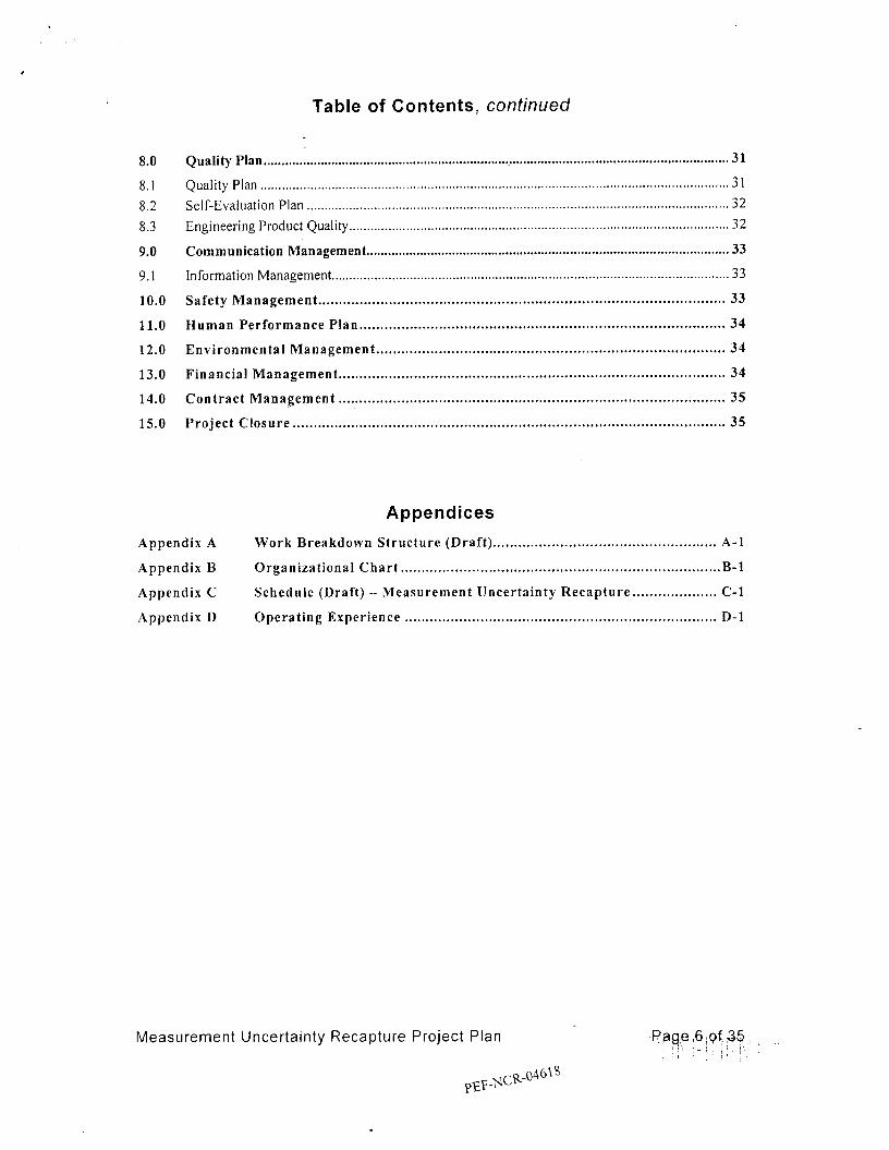
Table of Contents, continued
8.0
8.1 8.2 8.3
9.0
9.1
10.0
11.0
12.0
13.0
14.0
15.0
Quality Plan ......................................................................... . ............................. . ...... . ........... . .... ....31
.................................... 3 1 Self-Evaluation Plan ........................................ ................................................. 32 Engineering Product Quality ................ .... ........ ................................................................ 32
Communication Management .........................................,........................................................... 33
Information Management.
Safety Management ................................................................................................. 33
Human Performance Plan ....................................................................................... 3 4
Environmental Management .......................................................................,........... 3 4
Financial Management ............................................................................................ 34
Contract Management ......,..................................................................................... 35
Project Closure ....................................................................................................... 3 5
.............................................. * ......
............ ........ ................ ... ........ *. ............ .... ................... , ..... , .....
Appendices
Appendix A
Appendix B
Appendix C
Appendix D
Work Breakdown Structure (Draft) ..................................................... A-1
Organizational Chart ..... ... .. .... .. . .. .. ....... ... , .... , .... . .... . . . . . . .. . . . . . . . . . ... . .. . .. . . . . B- 1
Schedule (Draft) - Measurement Uncertainty Recapture .................... C-1
Operating Experience .......................................................................... D-1
Measurement Uncertainty Recapture Project Plan

OPC 1 st POD
#7
080009
BATES NOS. PEF-NCR 046 19 THROUGH PEF-NCR-04758A
REDACTED

Crystal River Unit 3
Extended Power Uprate
Project Plan
MASTER PROJECT NUMBER 20058849
Revision History 1 -I--- __
1 -
. P E I: -N C R - 04 7 5 9

Change Basis for Revision
Original Issue
Extended Power Uprate Project Plan Page 2 of 52
PEF-NCK-04760

Executive Summary
Crystal River Unit 3 (CR3) was initially licensed to operate at a maximum core thermal power level of 2352 MWt. In Technical Specification Amendment 41, dated July 21, 1981, the NRC approved operation of CR3 up to 2544MWt. Subsequently, Amendment 205 was issued by the NRC in 2002 approving a steady-state maximum core power level increase to 2568 MWt. CR3 is currently licensed to operate up to 2568 MWt.
A Measurement Uncertainty Recapture (MUR) power uprate has been initiated and is scheduled for implementation, pending NRC approval, in December 2007. The MUR modifications will allow CK3 to operate up to 2609 MWt. In addition to the 2609 MWt MUR power uprate, CR3 is pursuing thermal efficiency improvements scheduled for implementation in 2009, and an Extended Power Uprate (EPU), expected to be 3014 MWt, scheduled for implementation in 201 1 . The two phases of the Crystal River 3 Power Uprate Project will be implemented in the refueling outages of 2009 and 201 1. Each phase enumerated below contains definitive commercial and technical objectives:
Phase I - Balance of Plant Eff ic iency
Replacement of Low Pressure Turbines, Moisture Separator Reheaters (MSR), and Feedwater Heaters coincident w i t h the planned steam generator replacement wi l l increase the thermal efficiency of the secondary side of the plant to attain a 3% increase i n electrical power or 2 8 MWe with no change in t he rma l power.
Phase 1 implementation is scheduled for 2009, during 16R.
Phase II - Extended Power Uprate
N u m e r o u s p l a n t modifications including new Condensate, Circulating Wate r and Feedwater Booster pumpsimotors, along with and a significant Licensing effort, will enable reactor thermal output to increase by 17% to a total power of 3014 M W t with a corresponding electrical output of approximately 1080 MWe.
I’hasc I I Implementation is scheduled for 201 I , followir~g I 7 R .
’I‘his is the Project Plan for the Extended Power Uprate Project and focuscs on phases I and I I activities ;is listed above. Identified herein are the project management tools, techniques and instructions necessary to achieve project goals and objectivcs while minimizing cost and risk. Management plans to implement work activities include:
Project Vision, Mission Statement and Charter
Scope. Schedule, Cost and Risk Management Plans
Contract. Procurement and Quality Management P1:1ns
I luman Kcsource and Communication Management I’lans
Safety. I luman Performance and Environmental Management Plans
Rased on Progress Energy Nuclear Generation Group procedures and managernent guidelines, this Project Plan incorporates operating experience and the best project managenlent practices of the industry.
Extended Power Uprate Project Plan Page 3 of 52
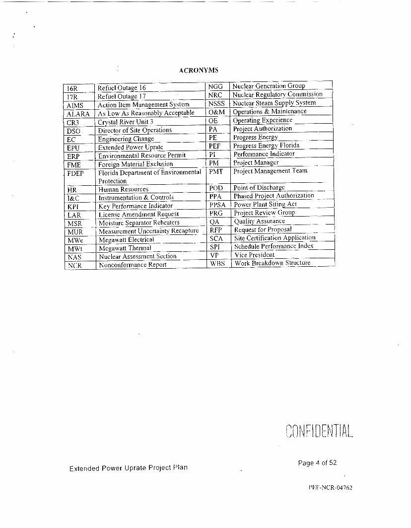
ACRONYMS
Extended Power Uprate Project Plan Page 4 of 52
PEF-NCR-04762

Table of Contents
Executive Summary Acronyms Table of Contents 1.0 1 . 1 1.2 1.3 1.4 1.5 I .6 1.7 1.8 1.9 1.10 1 . 1 1 2.0 2. I 2.2 2.3 2.4 3.0 3.1 3 .2 4.0 4.1 4.2 4.3 4.4 4.5 4.6 4.1 4.8 4.9 4.10 5.0 5. I 5.2 6.0 7.0
Integration Management Introduction and Business Case Implementation Approach Project Mission and Goal C 11 art er Scope Overview Scope Related Considerations & Assumptions Critical Success Factors Technical Objectives Performance Objectives Project Goals Project Acceptance Criteria Scope Management Plan Scope Statement Work Breakdown Structure (WBS) W B S Dictionary Scope Control Process Schedule Development and Management Plan S c hed u 1 e D eve 1 op in en t PI ann in g Schedule Man age men t Res o u rc e s Man age ni e n t Organizational Structiire P r o j e c t Sponsor K e s p o ii s i b i 1 i t i e s Project Manager (P M ) Responsi bi I i t ies Superintendent Major Projects Nuslear - Responsibilities Supervisor Engineering - Component Responsibilities S 11 perv i sor Mechanic al/C i v i I Design Ke s po II s i b i I it i cs Supervisor Design Engineering Electrical/l&C Responsibilities E rig i nee r i ng Team M em be r Res pons i b i I it i e s
S u per i n t enden t M aj or Projects - I in p I e mentation K e s po 11 s i b i I i t i es
Nuclear Project Constrtiction Support Organization I<oles K: Responsibilities Cost Management F i 11 aiic i a I Con t r o I s
Project Cost Estimate Risk Management I' r o c u rem en t Ma nag em e n t
Extended Power Uprate Project Plan
4 5 7 7 9 9
I O I I 1 1 13 14 16 1 8 18 19 19 19 19 20 22 22 23 25 2 5 26 26 28 29 2 9 30 31 33 34 38 38 38 39 40
Page 5 of 52
PEF-NCK-04763

OPC 1 POD st
#8
080009

OPC st 1 POD
#9
080009

lLOIEE LABOR
ICH MATUFURNIEOUIPISUPPLIES
.SIDE LABOR SVC EMPLOYED
IER COSTS
Total
PROGRESS ENERGY COMPANY CONFIDENTIAL EXTENDED POWER UPRATE (Including Point of Discharge)
Does Not Include AFUDC 2008 Variance Report (Actoals Through March 2008)
Fcb M., AP. May J"" Jul A w 5.P NO" Dr MarchYTD AJlW.1
Budget
Budgel
CONFIDENTII!!.


PROGRESS ENERGY COMPANY CONFIDENTIAL EXTENDED POWER UPRATE (Including Point of Discharge)
Does Not Include AFUDC
PURCH U~WURNIEQUIPISUPPUES
2006 Variance Report
P,o(SCla, 0 0 0 0 0 0 0 0 0 0 0 0 0 pm).Saon: - 0 &I!& 0 0 0 0 0 0 0 0 0
Budgal Vananre FavllUnlavi 0 0 0 0 0 0 0 0 0 0 (3.575) (33.736) (17.311) :Izrivt 0
Pra,echoo "ananie Fa"l("nfa"1 0 0 0 0 0 0 0 0 0 0 (3.575) (33.736) (17.311)
Bildoef 0 0 0 0 0 0 0 0 0 0 0 0 0 Budgel: 0
0 0 0 0 0 0 0 0 0 0 0 0 0 Buds& I R d g d
ProlKbm- 0 0 0 0 0 0 0 0 0 0 0 0 0
&&& 0 0 0 0 0 0 0 0 0 0 0 R t i d g ~ l L'anance FaWUnlav) 0 0 0 0 0 0 0 0 0 0 0 (28.148) (28.148)
Proiecl#on Vananre Favl(llnfavi 0 0 0 0 0 0 0 0 0 0 0 (~8.148)1 128.1481
P-m:
::zriv,
OmER COSTS
Total
Q
0
Prqcdo". 0 0 0 0 0 0 0 0 0 0 0 0 0 Prqeam: - 0 0 9 0 0 0 0 0 0 - 0 0 - 1 . 5 W . 5 1 T ( - 0 0 0 0 0 0 0 0 0
0 0 0 0 0 0 0 0 0
0 (638.351) (1.500.517) (2138.168)
0 (638.351) (1.500 517) (2.138.868)
0 F a v l f i h v l
Budget Variance Fau,(Unfavi
Prqcc lm vanancc Farl,"nla",
B.dgr, 0 0 0 0 0 0 0 0 0 0 0 0 0 Budget. 0
0 mqwm: e Prqectlon-
Budget Venancc FavliUnfav) 0 0 0 0 0 0 0 0 0 0
0 0 0 0 0 0 0 0 0 0 0 0
I\sN.l. 0 0 0 0 0 0 0 - 0 0 0 3 2 - 0 7 7 - ( =
0 (32.077) (63.269) (95.341) ::;Eav, 0 (32.077) (63 269) (95.147) 0 0 0 0 0 0 0 0 0 Proicctinn Vananre FauliUnlaui
0 0 0 0 0 0 0 0 0 0 0 0 BYdpsl 0 Budget 0
P.o("bon. 0 0 0 0 0 0 0 0 0 0 0 0 0
BudgelVarlansc F.W(Unhv): 0 0 0 0 0 0 0 0 0 0
0 Prqnctlon:
0 (6T4.0011 (1,625,670) (2.299.573) 2z:zhv, 0 (674.001) (1.625.670) (2,299,675)
0 0 0 0 0 0 0 - - - - - - 0 0 &!x& - - - - 0 w - m
0 0 0 0 0 0 0 0 0 P r o J 4 o n Vmlan~s FavlIUnhy:
OUTSIDE LABOR SVC EMPLOYE0 0 0 0 0 0 0 0 0 0 0 0 0 0 Budpet' I Budgcf
PEF-NCR-05264

st 1 P C 0
#I 0
080009

0 st 1 P
C 0
#I I
080009

Docket NO. U6ulir-ti
OPC's 1" Set for Production of Documents (Nos. 1-11)
Witness: Garrett AlTACH M ENT "A"
Sum:/ 2,299,673.06 I
1

VuCnFL 1 . u . U U U I I J L a
OPC’S I” Set for Production of Documents (Nos. 1-11)
Witness: Garrett A l l A C H MENT “6”
Joint Owner vs. Progress Energy Costs Summary of Power Uprate WO 20058849
Gross Charges 2007 - 2006 - Total
39,075,373.31 2,299,673.06 41,375,046.37 -
JO Exclusions (AFUDC and Other) -951,630.44 0.00 -951,630.44 JO gross charges 38,123,742.87 2,299,673.06 40,423,415.93
JO paid
Gross Charges JO paid Net Charges paid by PEF
x 8.2194% x 8.2194% x 8.2194% 3,133,542.92 189,019.33 3,322,562.25
39.075,373.37 2,299,673.06 41,375,046.37 3,133,542.92 189,019.33 3,322,562.25
35,941,830.39 2 , 1 1 0 , 6 5 3 x 38,052,484.12 In Power Plant a s of Dec 31, 2007
R:\Nuclear Cost Recovery (NCR)\Dockets\Data Respository Docs\[JO power uprate project-recap-2.xlsJSummary
Source: Emily Gibson, Accounting 03/31 108
~ E F -NCR-05266

2006 r&. s ( 4 2 186 2 1 1
Docket NO. 080119-El OPC’s lst Set for Production of
Documents (Nos. 1-11) Witness: Garrett
ATTACHMENT “C”
---_- R \Nuclear Cost Recovery (NCR)\Dockals\Scheduics\Suppon\Power Planl_Liprale projec! 200588491 ds
pEF-NCR-05267