Service and Troubleshooting - Alpine Home Air Products
114
Service and Troubleshooting *VXC20 Inverter Air Conditioner Condenser Units with R-410A Refrigerant Copyright © 2015-2017, 2020-2021 Goodman Manufacturing Company, L.P. RS6115001r11 March 2021 ® is a registered trademark of Maytag Corporation or its related companies and is used under license. All rights reserved. TABLE OF CONTENTS IMPORTANT INFORMATION ............................................. 2 PRODUCT IDENTIFICATION ............................................ 4 SYSTEM OPERATION ....................................................... 6 SERVICING ...................................................................... 13 CHECKING VOLTAGE ............................................... 13 CHECKING WIRING ................................................... 13 CHECKNG THERMOSTAT, WIRING ......................... 13 THERMOSTAT AND WIRING ..................................... 13 THERMOSTAT COMFORTBRIDGE™ SYSTEM ...... 13 COMFORTBRIDGE™ SYSTEM WIRING ................. 13 CHECKING TRANSFORMER AND CONTROL CIRCUIT ....................................................................... 14 CHECKING HIGH PRESSURE SWITCH .................. 14 CHECKING OUTDOOR AND OUTDOOR HI/LOW PRESSURE SENSOR................................................. 14 RESISTANCE CHECK (5 TON ONLY) ....................... 15 CAPACITANCE CHECK (5 TON ONLY) .................... 15 CHECKING COMPRESSOR ...................................... 15 COMPRESSOR WINDING INSULATION TEST ....... 16 GROUND TEST ........................................................... 16 TESTING CRANKCASE HEATER (5 TON ONLY) .... 17 TESTING TEMPERATURE SENSORS AND EEV COIL RESISTANCE..................................................... 17 TESTING EEV COIL RESISTANCE (AVPEC AIR HANDLER) ................................................................... 17 AVPEC HEATER CONTROL (OPTIONAL) ................ 17 REFRIGERATION REPAIR PRACTICE .................... 18 LEAK TESTING (NITROGEN OR NITRO- GEN-TRACED) ............................................................ 19 EVACUATION .............................................................. 19 CHARGING .................................................................. 20 CHECKING COMPRESSOR EFFICIENCY .............. 21 THERMOSTATIC EXPANSION VALVE ..................... 21 OVERFEEDING ........................................................... 21 Pride and workmanship go into every product to provide our customers with quality products. It is possible, however, that during its lifetime a product may require service. Products should be serviced only by a qualified service technician who is familiar with the safety procedures required in the repair and who is equipped with the proper tools, parts, testing instruments and the appropriate service manual. REVIEW ALL SERVICE INFORMATION IN THE APPROPRIATE SERVICE MANUAL BEFORE BEGINNING REPAIRS. Only personnel that have been trained to install, adjust, service or repair(hereinafter, “service”) the equipment specified in this manual should service the equipment. The manufacturer will not be responsible for any injury or property damage arising from improper service or service procedures. If you service this unit, you assume responsi- bility for any injury or property damage which may re- sult. In addition, in jurisdictions that require one or more licenses to service the equipment specified in this manual, only licensed personnel should servise the equipment. Improper installation, adjustment, servicing or repair of the equipment specified in this manual, or attempting to install, adjust, service or repair the equipment specified in this manual without proper training may result in product damage, property damage, personal injury or death. WARNING For service information related to the Bluetooth® Shared Data Loader BTSDL01 referenced in this manual, please refer to the installation instructions for the BTSDL01 at www.coolcloudhvac.com/loaderuserguide
-
Upload
khangminh22 -
Category
Documents
-
view
1 -
download
0
Transcript of Service and Troubleshooting - Alpine Home Air Products
Service and Troubleshooting*VXC20 Inverter Air Conditioner Condenser Units with R-410A Refrigerant
Copyright © 2015-2017, 2020-2021 Goodman Manufacturing Company, L.P.
RS6115001r11March 2021
® is a registered trademark of Maytag Corporation or its related companies and is used under license. All rights reserved.
TABLE OF CONTENTS
IMPORTANT INFORMATION ............................................. 2PRODUCT IDENTIFICATION ............................................ 4SYSTEM OPERATION ....................................................... 6SERVICING ...................................................................... 13
CHECKING VOLTAGE ............................................... 13CHECKING WIRING ................................................... 13 CHECKNG THERMOSTAT, WIRING ......................... 13THERMOSTAT AND WIRING ..................................... 13THERMOSTAT COMFORTBRIDGE™ SYSTEM ...... 13 COMFORTBRIDGE™ SYSTEM WIRING ................. 13CHECKING TRANSFORMER AND CONTROL CIRCUIT ....................................................................... 14CHECKING HIGH PRESSURE SWITCH .................. 14CHECKING OUTDOOR AND OUTDOOR HI/LOW PRESSURE SENSOR................................................. 14RESISTANCE CHECK (5 TON ONLY) ....................... 15 CAPACITANCE CHECK (5 TON ONLY) .................... 15 CHECKING COMPRESSOR ...................................... 15COMPRESSOR WINDING INSULATION TEST ....... 16 GROUND TEST ........................................................... 16TESTING CRANKCASE HEATER (5 TON ONLY) .... 17 TESTING TEMPERATURE SENSORS AND EEV COIL RESISTANCE..................................................... 17TESTING EEV COIL RESISTANCE (AVPEC AIR HANDLER) ................................................................... 17 AVPEC HEATER CONTROL (OPTIONAL) ................ 17REFRIGERATION REPAIR PRACTICE .................... 18LEAK TESTING (NITROGEN OR NITRO-GEN-TRACED) ............................................................ 19 EVACUATION .............................................................. 19CHARGING .................................................................. 20CHECKING COMPRESSOR EFFICIENCY .............. 21THERMOSTATIC EXPANSION VALVE ..................... 21OVERFEEDING ........................................................... 21
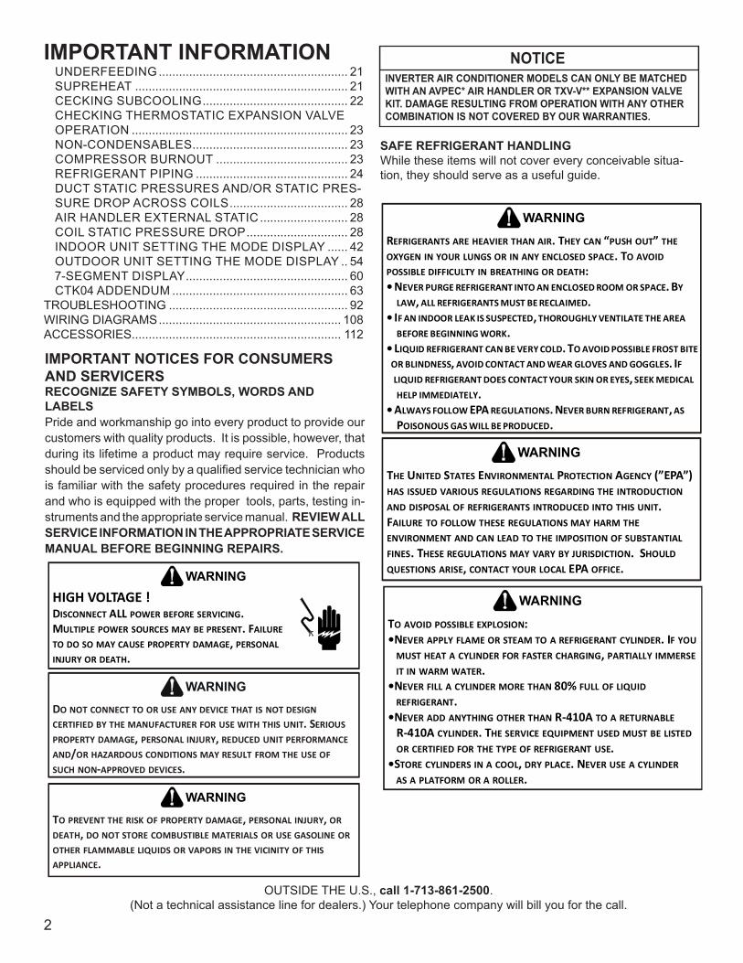
Pride and workmanship go into every product to provide our customers with quality products. It is possible, however,that during its lifetime a product may require service. Products should be serviced only by a qualified service technician who is familiar with the safety procedures required in the repair and who is equipped with the proper tools, parts, testing instruments and the appropriate service manual. REVIEW ALL SERVICE INFORMATION IN THE APPROPRIATE SERVICE MANUAL BEFORE BEGINNING REPAIRS.
Only personnel that have been trained to install, adjust, service or repair(hereinafter, “service”) the equipment specified in this manual should service the equipment. The manufacturer will not be responsible for any injury or property damage arising from improper service or service procedures. If you service this unit, you assume responsi-bility for any injury or property damage which may re-sult. In addition, in jurisdictions that require one or more licenses to service the equipment specified in this manual, only licensed personnel should servise the equipment. Improper installation, adjustment, servicing or repair of the equipment specified in this manual, or attempting to install, adjust, service or repair the equipment specified in this manual without proper training may result in product damage, property damage, personal injury or death.
WARNING
For service information related to the Bluetooth® SharedData Loader BTSDL01 referenced in this manual, pleaserefer to the installation instructions for the BTSDL01 atwww.coolcloudhvac.com/loaderuserguide
IMPORTANT INFORMATION
2
IMPORTANT NOTICES FOR CONSUMERS AND SERVICERSRECOGNIZE SAFETY SYMBOLS, WORDS AND LABELSPride and workmanship go into every product to provide our customers with quality products. It is possible, however, that during its lifetime a product may require service. Products should be serviced only by a qualified service technician who is familiar with the safety procedures required in the repair and who is equipped with the proper tools, parts, testing in-struments and the appropriate service manual. REVIEW ALL SERVICE INFORMATION IN THE APPROPRIATE SERVICE MANUAL BEFORE BEGINNING REPAIRS.
OUTSIDE THE U.S., call 1-713-861-2500.(Not a technical assistance line for dealers.) Your telephone company will bill you for the call.
HIGH VOLTAGE !DISCONNECT ALL POWER BEFORE SERVICING. MULTIPLE POWER SOURCES MAY BE PRESENT. FAILURE TO DO SO MAY CAUSE PROPERTY DAMAGE, PERSONAL INJURY OR DEATH.
WARNING
DO NOT CONNECT TO OR USE ANY DEVICE THAT IS NOT DESIGN CERTIFIED BY THE MANUFACTURER FOR USE WITH THIS UNIT. SERIOUS PROPERTY DAMAGE, PERSONAL INJURY, REDUCED UNIT PERFORMANCE AND/OR HAZARDOUS CONDITIONS MAY RESULT FROM THE USE OF SUCH NON-APPROVED DEVICES.
WARNING
TO PREVENT THE RISK OF PROPERTY DAMAGE, PERSONAL INJURY, OR DEATH, DO NOT STORE COMBUSTIBLE MATERIALS OR USE GASOLINE OR OTHER FLAMMABLE LIQUIDS OR VAPORS IN THE VICINITY OF THIS APPLIANCE.
WARNING
SAFE REFRIGERANT HANDLINGWhile these items will not cover every conceivable situa-tion, they should serve as a useful guide.
REFRIGERANTS ARE HEAVIER THAN AIR. THEY CAN “PUSH OUT” THE OXYGEN IN YOUR LUNGS OR IN ANY ENCLOSED SPACE. TO AVOID POSSIBLE DIFFICULTY IN BREATHING OR DEATH:• NEVER PURGE REFRIGERANT INTO AN ENCLOSED ROOM OR SPACE. BY LAW, ALL REFRIGERANTS MUST BE RECLAIMED.• IF AN INDOOR LEAK IS SUSPECTED, THOROUGHLY VENTILATE THE AREA BEFORE BEGINNING WORK.• LIQUID REFRIGERANT CAN BE VERY COLD. TO AVOID POSSIBLE FROST BITE OR BLINDNESS, AVOID CONTACT AND WEAR GLOVES AND GOGGLES. IF LIQUID REFRIGERANT DOES CONTACT YOUR SKIN OR EYES, SEEK MEDICAL HELP IMMEDIATELY.• ALWAYS FOLLOW EPA REGULATIONS. NEVER BURN REFRIGERANT, AS POISONOUS GAS WILL BE PRODUCED.
WARNING
THE UNITED STATES ENVIRONMENTAL PROTECTION AGENCY (”EPA”) HAS ISSUED VARIOUS REGULATIONS REGARDING THE INTRODUCTION AND DISPOSAL OF REFRIGERANTS INTRODUCED INTO THIS UNIT.FAILURE TO FOLLOW THESE REGULATIONS MAY HARM THE ENVIRONMENT AND CAN LEAD TO THE IMPOSITION OF SUBSTANTIAL FINES. THESE REGULATIONS MAY VARY BY JURISDICTION. SHOULD QUESTIONS ARISE, CONTACT YOUR LOCAL EPA OFFICE.
WARNING
TO AVOID POSSIBLE EXPLOSION:•NEVER APPLY FLAME OR STEAM TO A REFRIGERANT CYLINDER. IF YOU
MUST HEAT A CYLINDER FOR FASTER CHARGING, PARTIALLY IMMERSE IT IN WARM WATER.
•NEVER FILL A CYLINDER MORE THAN 80% FULL OF LIQUID REFRIGERANT.
•NEVER ADD ANYTHING OTHER THAN R-410A TO A RETURNABLE R-410A CYLINDER. THE SERVICE EQUIPMENT USED MUST BE LISTED OR CERTIFIED FOR THE TYPE OF REFRIGERANT USE.•STORE CYLINDERS IN A COOL, DRY PLACE. NEVER USE A CYLINDER
AS A PLATFORM OR A ROLLER.
WARNING
UNDERFEEDING ........................................................ 21SUPREHEAT ............................................................... 21CECKING SUBCOOLING ........................................... 22CHECKING THERMOSTATIC EXPANSION VALVE OPERATION ................................................................ 23NON-CONDENSABLES .............................................. 23 COMPRESSOR BURNOUT ....................................... 23REFRIGERANT PIPING ............................................. 24DUCT STATIC PRESSURES AND/OR STATIC PRES-SURE DROP ACROSS COILS ................................... 28AIR HANDLER EXTERNAL STATIC .......................... 28COIL STATIC PRESSURE DROP .............................. 28INDOOR UNIT SETTING THE MODE DISPLAY ...... 42OUTDOOR UNIT SETTING THE MODE DISPLAY .. 547-SEGMENT DISPLAY ................................................ 60CTK04 ADDENDUM .................................................... 63
TROUBLESHOOTING ..................................................... 92WIRING DIAGRAMS ...................................................... 108ACCESSORIES.............................................................. 112
NOTICEINVERTER AIR CONDITIONER MODELS CAN ONLY BE MATCHED WITH AN AVPEC* AIR HANDLER OR TXV-V** EXPANSION VALVE KIT. DAMAGE RESULTING FROM OPERATION WITH ANY OTHER COMBINATION IS NOT COVERED BY OUR WARRANTIES.
IMPORTANT INFORMATION
3
TO AVOID POSSIBLE INJURY, EXPLOSION OR DEATH, PRACTICE SAFE HANDLING OF REFRIGERANTS.
WARNING
THE COMPRESSOR PVE OIL FOR R-410A UNITS IS EXTREMELY SUSCEPTIBLE TO MOISTURE ABSORPTION AND COULD CAUSE COMPRESSOR FAILURE. DO NOT LEAVE SYSTEM OPEN TO ATMOSPHERE ANY LONGER THAN NECESSARY FOR INSTALLATION.
CAUTION
SYSTEM CONTAMINANTS, IMPROPER SERVICE PROCEDURE AND/OR PHYSICAL ABUSE AFFECTING HERMETIC COMPRESSOR ELECTRICAL TERMINALS MAY CAUSE DANGEROUS SYSTEM VENTING.
WARNING
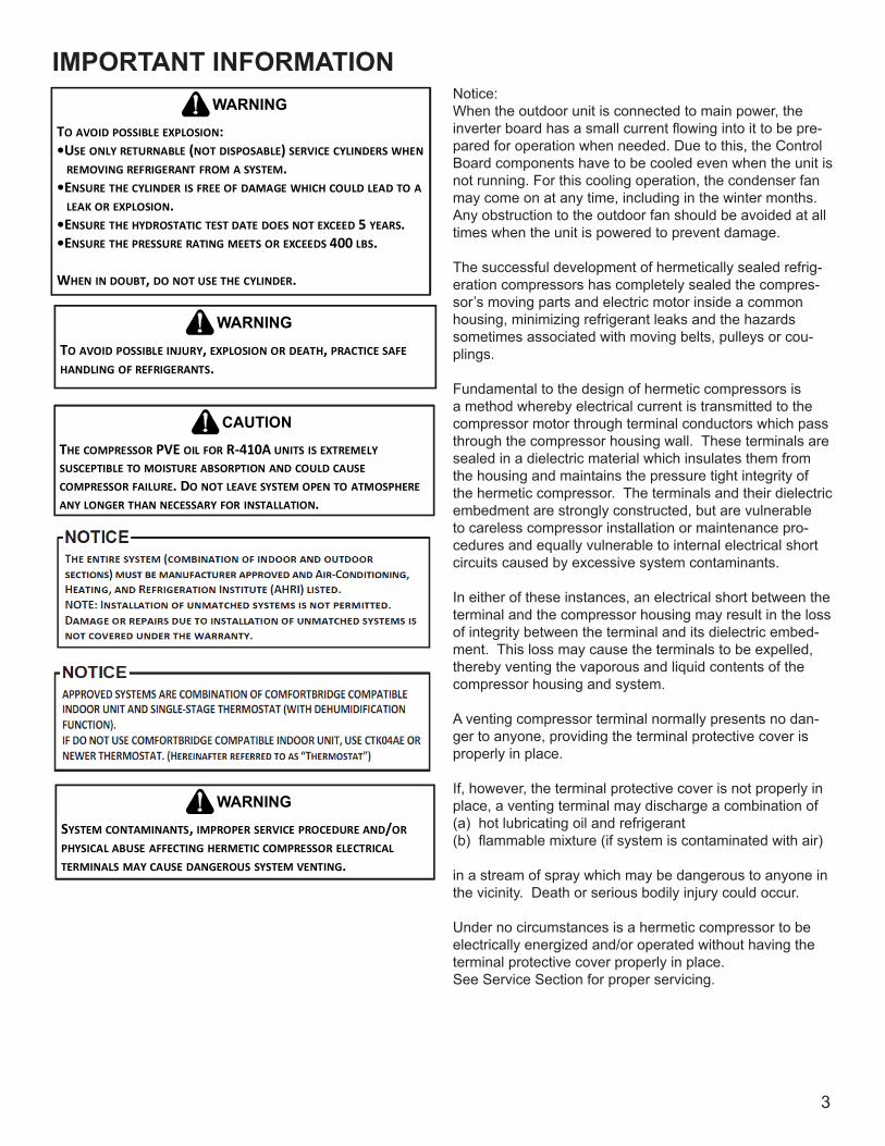
Notice:When the outdoor unit is connected to main power, the inverter board has a small current flowing into it to be pre-pared for operation when needed. Due to this, the Control Board components have to be cooled even when the unit is not running. For this cooling operation, the condenser fan may come on at any time, including in the winter months. Any obstruction to the outdoor fan should be avoided at all times when the unit is powered to prevent damage.
The successful development of hermetically sealed refrig-eration compressors has completely sealed the compres-sor’s moving parts and electric motor inside a common housing, minimizing refrigerant leaks and the hazards sometimes associated with moving belts, pulleys or cou-plings.
Fundamental to the design of hermetic compressors is a method whereby electrical current is transmitted to the compressor motor through terminal conductors which pass through the compressor housing wall. These terminals are sealed in a dielectric material which insulates them from the housing and maintains the pressure tight integrity of the hermetic compressor. The terminals and their dielectric embedment are strongly constructed, but are vulnerable to careless compressor installation or maintenance pro-cedures and equally vulnerable to internal electrical short circuits caused by excessive system contaminants.
In either of these instances, an electrical short between the terminal and the compressor housing may result in the loss of integrity between the terminal and its dielectric embed-ment. This loss may cause the terminals to be expelled, thereby venting the vaporous and liquid contents of the compressor housing and system.
A venting compressor terminal normally presents no dan-ger to anyone, providing the terminal protective cover is properly in place.
If, however, the terminal protective cover is not properly in place, a venting terminal may discharge a combination of (a) hot lubricating oil and refrigerant(b) flammable mixture (if system is contaminated with air)
in a stream of spray which may be dangerous to anyone in the vicinity. Death or serious bodily injury could occur.
Under no circumstances is a hermetic compressor to be electrically energized and/or operated without having the terminal protective cover properly in place.See Service Section for proper servicing.
TO AVOID POSSIBLE EXPLOSION:•USE ONLY RETURNABLE (NOT DISPOSABLE) SERVICE CYLINDERS WHEN
REMOVING REFRIGERANT FROM A SYSTEM.•ENSURE THE CYLINDER IS FREE OF DAMAGE WHICH COULD LEAD TO A
LEAK OR EXPLOSION.•ENSURE THE HYDROSTATIC TEST DATE DOES NOT EXCEED 5 YEARS.•ENSURE THE PRESSURE RATING MEETS OR EXCEEDS 400 LBS.
WHEN IN DOUBT, DO NOT USE THE CYLINDER.
WARNING
PRODUCT IDENTIFICATION
4
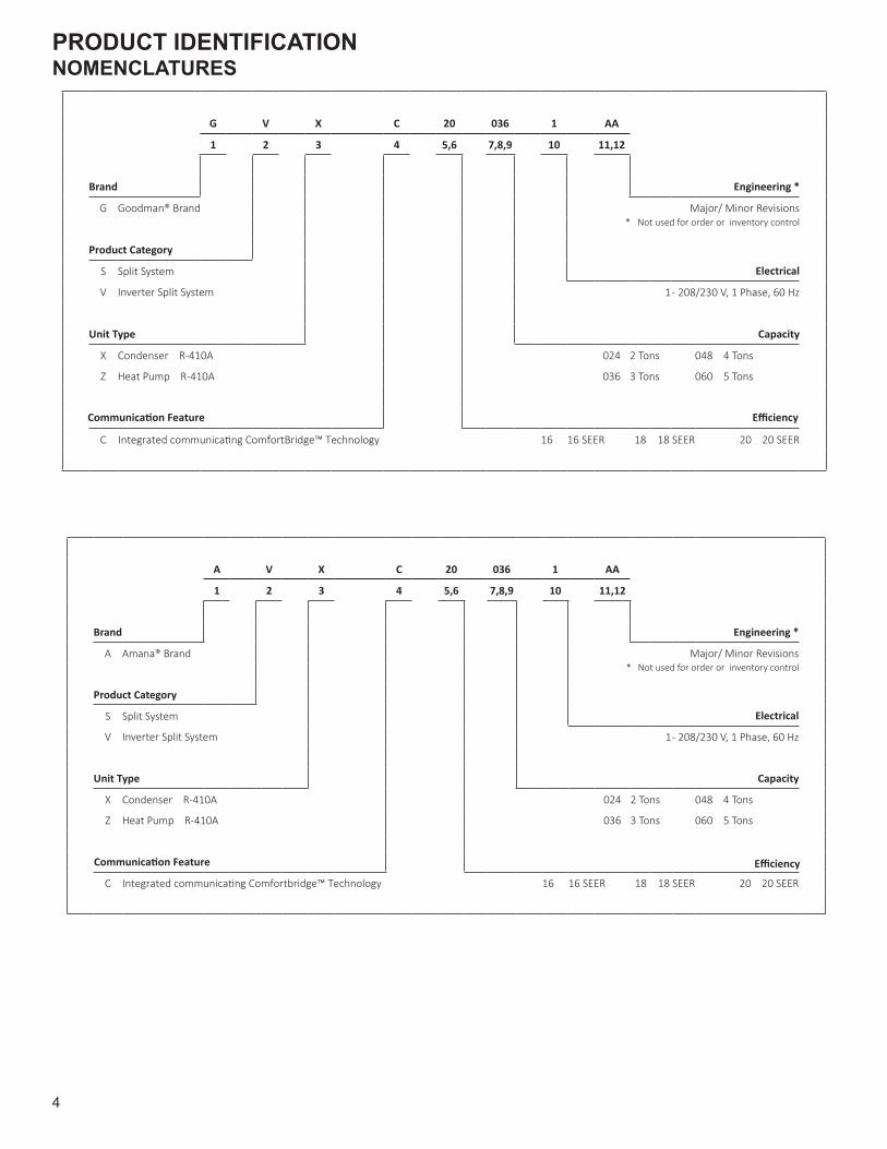
NOMENCLATURES
A V X C 20 036 1 AA
1 2 3 4 5,6 7,8,9 10 11,12
Brand Engineering *
A Amana® Brand Major/ Minor Revisions* Not used for order or inventory control
Product Category
S Split System Electrical
V Inverter Split System 1 - 208/230 V, 1 Phase, 60 Hz
Unit Type Capacity
X Condenser R-410A 024 2 Tons 048 4 Tons
Z Heat Pump R-410A 036 3 Tons 060 5 Tons
C 16 16 SEER 18 18 SEER 20 20 SEER
Communica�on Feature
Integrated communica�ng Comfortbridge™ Technology
Efficiency
G V X C 20 036 1 AA
1 2 3 4 5,6 7,8,9 10 11,12
Brand Engineering *
G Goodman® Brand Major/ Minor Revisions* Not used for order or inventory control
Product Category
S Split System Electrical
V Inverter Split System 1 - 208/230 V, 1 Phase, 60 Hz
Unit Type Capacity
X Condenser R-410A 024 2 Tons 048 4 Tons
Z Heat Pump R-410A 036 3 Tons 060 5 Tons
C 16 16 SEER 18 18 SEER 20 20 SEER
Communica�on Feature
Integrated communica�ng ComfortBridge™ Technology
Efficiency

PRODUCT IDENTIFICATION
5
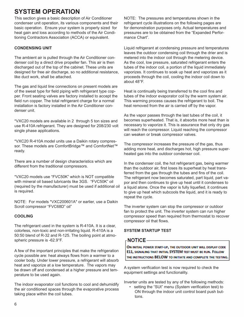
A V P E C 25 B 1 4 AA
1 2 3 4 5 6,7 8 9 10 11,12
Brand Engineering*
A Single-Piece Air Handler Major/Minor Revisions
*Not used for inventory management
Unit Applica�on Refrigerant Charge
R 4 = R-410A
S
V Electrical
1 208/230V, 1 Phase, 60 Hz
Cabinet Finish Cabinet Width
U Unpainted B = 17½"
P Painted "12 = C
D = 24½"
Expansion Device
E Electronic Expansion Valve Nominal Capacity @ 13 SEER
T Expansion Device 24 = 2 Tons 31 = 2½ Tons 48 = 4 Tons
V Inverter Tuned Expansion Valve 25 = 2 Tons 36 = 3 Tons 49 =3-3½ Tons
29 = 2 Tons 37 = 3½ Tons 59 = 4-5 Tons
Communica�ons 30 = 2½ Tons 42 = 3½ Tons 60 = 5 Tons
C = ComfortNet™ Compa�ble 61 = 4-5 Tons
Mul� Posi�on PSC Motor
Mul� Posi�on EEM Motor
Mul� Posi�on Variable-SpeedMotor - Communica�ng
NOMENCLATURES
SYSTEM OPERATION
6
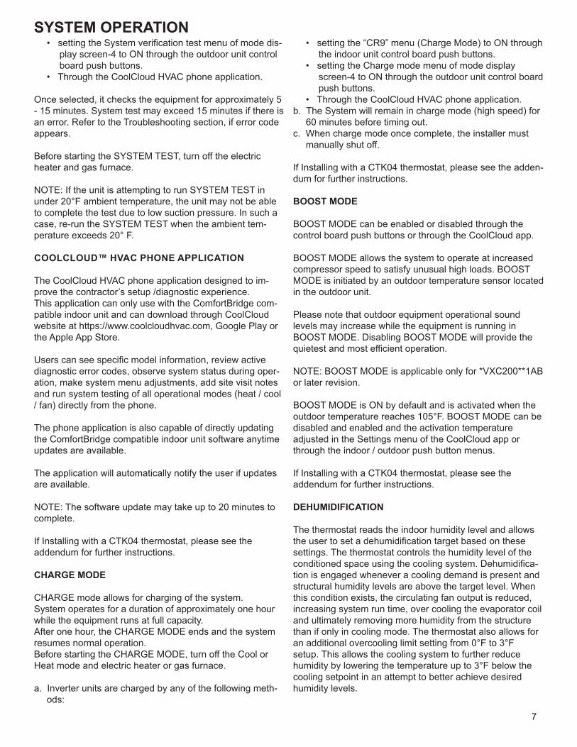
This section gives a basic description of Air Conditioner condenser unit operation, its various components and their basic operation. Ensure your system is properly sized for heat gain and loss according to methods of the Air Condi-tioning Contractors Association (ACCA) or equivalent.
CONDENSING UNIT
The ambient air is pulled through the Air Conditioner con-denser coil by a direct drive propeller fan. This air is then discharged out of the top of the cabinet. These units are designed for free air discharge, so no additional resistance, like duct work, shall be attached.
The gas and liquid line connections on present models are of the sweat type for field piping with refrigerant type cop-per. Front seating valves are factory installed to accept the field run copper. The total refrigerant charge for a normal installation is factory installed in the Air Conditioner con-denser unit.
*VXC20 models are available in 2 through 5 ton sizes and use R-410A refrigerant. They are designed for 208/230 volt single phase applications.
*VXC20 R-410A model units use a Daikin rotary compres-sor. These models are ComfortBridge™ and ComfortNet™ ready.
There are a number of design characteristics which are different from the traditional compressors.
*VXC20 models use “FVC50K” which is NOT compatible with mineral oil based lubricants like 3GS. “FVC50K” oil (required by the manufacturer) must be used if additional oil is required.
NOTE: For models *VXC200601A* or earlier, use a Daikin Scroll compressor “FVC68D” oil”
COOLING
The refrigerant used in the system is R-410A. It is a clear, colorless, non-toxic and non-irritating liquid. R-410A is a 50:50 blend of R-32 and R-125. The boiling point at atmo-spheric pressure is -62.9°F.
A few of the important principles that make the refrigeration cycle possible are: heat always flows from a warmer to a cooler body. Under lower pressure, a refrigerant will absorb heat and vaporize at a low temperature. The vapors may be drawn off and condensed at a higher pressure and tem-perature to be used again.
The indoor evaporator coil functions to cool and dehumidify the air conditioned spaces through the evaporative process taking place within the coil tubes.
NOTE: The pressures and temperatures shown in the refrigerant cycle illustrations on the following pages are for demonstration purposes only. Actual temperatures and pressures are to be obtained from the “Expanded Perfor-mance Chart”.
Liquid refrigerant at condensing pressure and temperatures leaves the outdoor condensing coil through the drier and is metered into the indoor coil through the metering device. As the cool, low pressure, saturated refrigerant enters the tubes of the indoor coil, a portion of the liquid immediately vaporizes. It continues to soak up heat and vaporizes as it proceeds through the coil, cooling the indoor coil down to about 48°F.
Heat is continually being transferred to the cool fins and tubes of the indoor evaporator coil by the warm system air. This warming process causes the refrigerant to boil. The heat removed from the air is carried off by the vapor.
As the vapor passes through the last tubes of the coil, it becomes superheated. That is, it absorbs more heat than is necessary to vaporize it. This is assurance that only dry gas will reach the compressor. Liquid reaching the compressor can weaken or break compressor valves.
The compressor increases the pressure of the gas, thus adding more heat, and discharges hot, high pressure super-heated gas into the outdoor condenser coil.
In the condenser coil, the hot refrigerant gas, being warmer than the outdoor air, first loses its superheat by heat trans-ferred from the gas through the tubes and fins of the coil. The refrigerant now becomes saturated, part liquid, part va-por and then continues to give up heat until it condenses to a liquid alone. Once the vapor is fully liquefied, it continues to give up heat which subcools the liquid, and it is ready to repeat the cycle.
The inverter system can stop the compressor or outdoor fan to protect the unit. The inverter system can run higher compressor speed than required from thermostat to recover compressor oil that flows.
SYSTEM STARTUP TEST
A system verification test is now required to check theequipment settings and functionality.
Inverter units are tested by any of the following methods:• setting the “SUt” menu (System verification test) to
ON through the indoor unit control board push but-tons.
SYSTEM OPERATION
7
• setting the System verification test menu of mode dis-play screen-4 to ON through the outdoor unit control board push buttons.
• Through the CoolCloud HVAC phone application.
Once selected, it checks the equipment for approximately 5 - 15 minutes. System test may exceed 15 minutes if there is an error. Refer to the Troubleshooting section, if error codeappears.
Before starting the SYSTEM TEST, turn off the electric heater and gas furnace.
NOTE: If the unit is attempting to run SYSTEM TEST in under 20°F ambient temperature, the unit may not be able to complete the test due to low suction pressure. In such a case, re-run the SYSTEM TEST when the ambient tem-perature exceeds 20° F.
COOLCLOUD™ HVAC PHONE APPLICATION
The CoolCloud HVAC phone application designed to im-prove the contractor’s setup /diagnostic experience.This application can only use with the ComfortBridge com-patible indoor unit and can download through CoolCloud website at https://www.coolcloudhvac.com, Google Play or the Apple App Store.
Users can see specific model information, review activediagnostic error codes, observe system status during oper-ation, make system menu adjustments, add site visit notes and run system testing of all operational modes (heat / cool / fan) directly from the phone.
The phone application is also capable of directly updating the ComfortBridge compatible indoor unit software anytimeupdates are available.
The application will automatically notify the user if updates are available.
NOTE: The software update may take up to 20 minutes tocomplete.
If Installing with a CTK04 thermostat, please see the addendum for further instructions.
CHARGE MODE
CHARGE mode allows for charging of the system.System operates for a duration of approximately one hourwhile the equipment runs at full capacity.After one hour, the CHARGE MODE ends and the systemresumes normal operation.Before starting the CHARGE MODE, turn off the Cool orHeat mode and electric heater or gas furnace.
a. Inverter units are charged by any of the following meth-ods:
• setting the “CR9” menu (Charge Mode) to ON through the indoor unit control board push buttons.
• setting the Charge mode menu of mode display screen-4 to ON through the outdoor unit control board push buttons.
• Through the CoolCloud HVAC phone application.b. The System will remain in charge mode (high speed) for
60 minutes before timing out.c. When charge mode once complete, the installer must
manually shut off.
If Installing with a CTK04 thermostat, please see the adden-dum for further instructions.
BOOST MODE
BOOST MODE can be enabled or disabled through thecontrol board push buttons or through the CoolCloud app.
BOOST MODE allows the system to operate at increasedcompressor speed to satisfy unusual high loads. BOOSTMODE is initiated by an outdoor temperature sensor locatedin the outdoor unit.
Please note that outdoor equipment operational soundlevels may increase while the equipment is running in BOOST MODE. Disabling BOOST MODE will provide the quietest and most efficient operation.
NOTE: BOOST MODE is applicable only for *VXC200**1AB or later revision.
BOOST MODE is ON by default and is activated when theoutdoor temperature reaches 105°F. BOOST MODE can bedisabled and enabled and the activation temperatureadjusted in the Settings menu of the CoolCloud app orthrough the indoor / outdoor push button menus.
If Installing with a CTK04 thermostat, please see the addendum for further instructions.
DEHUMIDIFICATION
The thermostat reads the indoor humidity level and allows the user to set a dehumidification target based on these settings. The thermostat controls the humidity level of the conditioned space using the cooling system. Dehumidifica-tion is engaged whenever a cooling demand is present and structural humidity levels are above the target level. When this condition exists, the circulating fan output is reduced, increasing system run time, over cooling the evaporator coil and ultimately removing more humidity from the structure than if only in cooling mode. The thermostat also allows for an additional overcooling limit setting from 0°F to 3°Fsetup. This allows the cooling system to further reduce humidity by lowering the temperature up to 3°F below the cooling setpoint in an attempt to better achieve desired humidity levels.
SYSTEM OPERATION
8
DEHUMIDIFICATION TIPS* (ComfortNet Systems Only)
For effective dehumidification operation:• Ensure “Dehumidification” is not set to “OFF”• Verify the cooling airflow profile (cool profiles) is set to
“Profile D”.- See the Cool Set-up section of the InstallatioN
Manual for complete airflow profile details.- By default, “dehumidification selection” is stan-
dard and the cooling airflow profile is set to “ProfileD”
• For additional dehumidification control, airflow settings are field adjustable and can be fine-tuned to a value that is comfortable for the application from a range of Cool Airflow Trim.
• In addition, the system can have Enhanced Dehumidification operation in setting “A”, “B”, or “C” of dehumidification based on dehumidification demand.
- See the Dehumidification Select section for more detail.*The specification of *VXC200241AF, 0361AE,0481AE, and 0601AE or earlier models are differentfrom this specification. For details, see theInstallation Manual or Service Manual that matchesthe Major and Minor revision of the model name.
COMFORTBRIDGE™ SYSTEM OVERVIEW
The ComfortBridge based inverter heating and air conditioning system uses an indoor unit and outdoor unit digitally communicating with one another via a two-way communications path.
The 24 VAC single-stage thermostat sends commands to the indoor and outdoor units.The indoor and outdoor units interacting with one anotherdirectly while taking simple analog commands from thethermostat are the core of unlocking the benefits and fea-tures of the ComfortBridge control system. NOTE: It is strongly recommend the use of thermostat with humidity sensor and dehumidification terminal.Without these functions, Dehumidification operation does not work.
COMFORTBRIDGE SYSTEM ADVANCED FEATURES
The ComfortBridge system permits access to additional system information, advanced set-up features, and ad-vanced diagnostic/troubleshooting features via the control board push buttons or the CoolCloud mobile app.(If using a CTK04 thermostat, please see the addendum forfurther instructions.)
FAULT CODE HISTORY
The Air Conditioner’s diagnostics menu provides access to the most recent faults. The six most recent faults can be ac-cessed through the control board seven segment displays or the CoolCloud mobile app. Any consecutively repeated fault is stored a maximum of three times.
Example: A leak in the system, low refrigerant charge or anincompletely open stop valve can cause the unit to flash error code E15. This error code suggests that the unit is experiencing operation at low pressure. The control will only store this fault the first three consecutive times the fault occurs.NOTE: The fault list can be cleared after performing maintenance or servicing the system to assist in the troubleshooting process.
DEVICE STATUS
This menu displays information about the systems currentstatus. This menu can be utilized to confirm correct func-tionality of the equipment and for troubleshooting purposes.
The following items will be displayed:• Heat Capacity Request Percentage• Cool Capacity Request Percentage• Heat Capacity Request During Defrost Percentage• Dehumidification Request Percentage• Reversing Valve Status• Reported Airflow by Indoor Unit• Boost Mode• Previous Defrost Run Time
SENSOR DATA
The following sensor items will be displayed:• Outdoor Temperature• Coil Temperature• Liquid Line Temperature• Discharge Temperature• Defrost Sensor• Suction Pressure
PUMP DOWN / CHARGE MODE
This function can be enabled this menu.
SET 7-SEGMENT MODE DISPLAY TO PUMP DOWN
Please follow the following sequence to enter PUMP DOWN to accumulate the refrigerant to outdoor unit by 7 Segment Mode. Do not operate COOL ON or HEAT ON mode to enter PUMP DOWN.
Before starting the PUMP DOWN operation, change indoor fan trim, delay and profile back to default and stop elec-tric heater and gas furnace. Remove if no trim feature. In this operation, the gas and liquid service valve should be opened.
1. Set 7-segment display to SCREEN 4 (SETTING MODE 2) Setting No. 8 and change the display from “-01” to “-00” System will then automatically start PUMP DOWN operation. For information on how to set 7-segment display, see the section SETTING THE MODE DISPLAY in this manual.
SYSTEM OPERATION
9
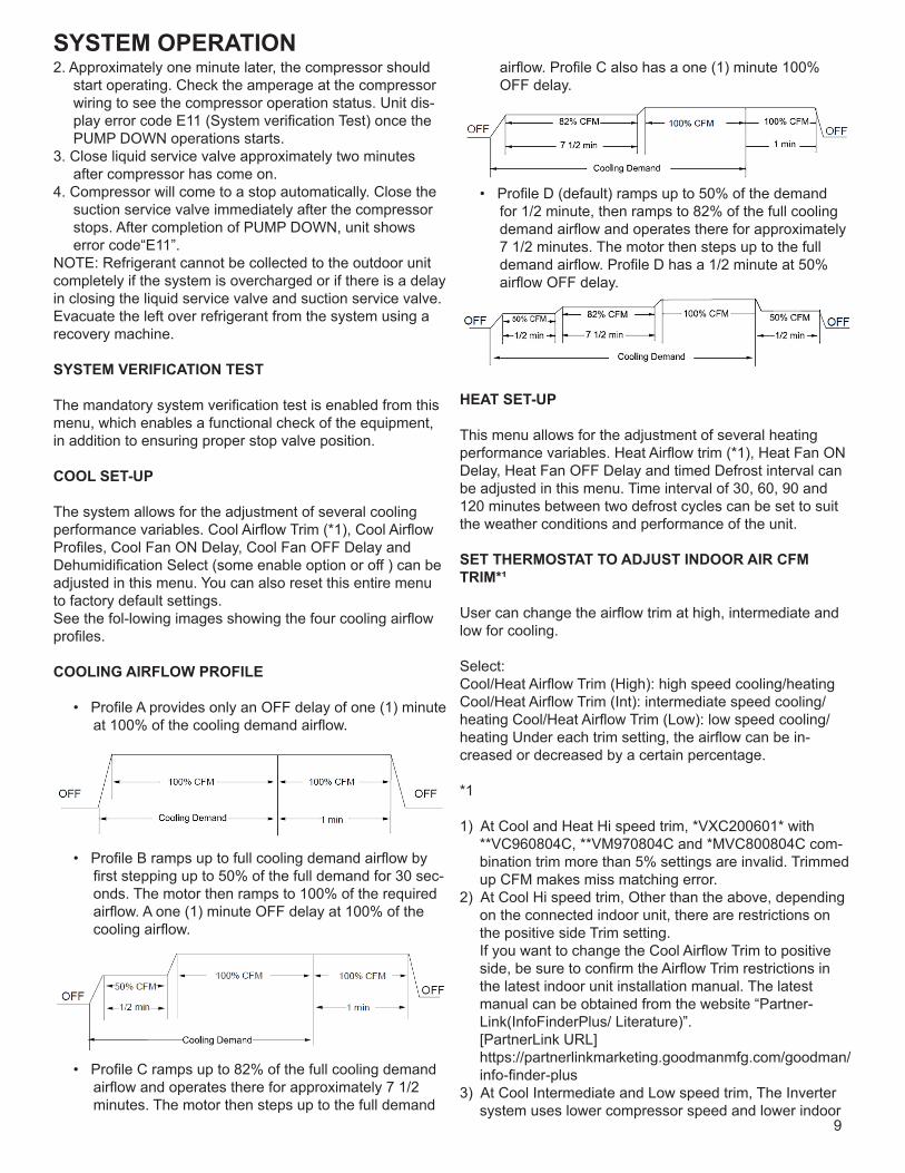
2. Approximately one minute later, the compressor should start operating. Check the amperage at the compressor wiring to see the compressor operation status. Unit dis-play error code E11 (System verification Test) once the PUMP DOWN operations starts.
3. Close liquid service valve approximately two minutes after compressor has come on.
4. Compressor will come to a stop automatically. Close the suction service valve immediately after the compressor stops. After completion of PUMP DOWN, unit shows error code“E11”.
NOTE: Refrigerant cannot be collected to the outdoor unit completely if the system is overcharged or if there is a delay in closing the liquid service valve and suction service valve. Evacuate the left over refrigerant from the system using a recovery machine.
SYSTEM VERIFICATION TEST
The mandatory system verification test is enabled from thismenu, which enables a functional check of the equipment, in addition to ensuring proper stop valve position.
COOL SET-UP
The system allows for the adjustment of several cooling performance variables. Cool Airflow Trim (*1), Cool Airflow Profiles, Cool Fan ON Delay, Cool Fan OFF Delay and Dehumidification Select (some enable option or off ) can be adjusted in this menu. You can also reset this entire menu to factory default settings.See the fol-lowing images showing the four cooling airflowprofiles.
COOLING AIRFLOW PROFILE
• Profile A provides only an OFF delay of one (1) minute at 100% of the cooling demand airflow.
• Profile B ramps up to full cooling demand airflow by first stepping up to 50% of the full demand for 30 sec-onds. The motor then ramps to 100% of the required airflow. A one (1) minute OFF delay at 100% of the cooling airflow.
• Profile C ramps up to 82% of the full cooling demand airflow and operates there for approximately 7 1/2 minutes. The motor then steps up to the full demand
airflow. Profile C also has a one (1) minute 100% OFF delay.
• Profile D (default) ramps up to 50% of the demand for 1/2 minute, then ramps to 82% of the full cooling demand airflow and operates there for approximately 7 1/2 minutes. The motor then steps up to the full demand airflow. Profile D has a 1/2 minute at 50% airflow OFF delay.
HEAT SET-UP
This menu allows for the adjustment of several heating performance variables. Heat Airflow trim (*1), Heat Fan ON Delay, Heat Fan OFF Delay and timed Defrost interval can be adjusted in this menu. Time interval of 30, 60, 90 and 120 minutes between two defrost cycles can be set to suit the weather conditions and performance of the unit.
SET THERMOSTAT TO ADJUST INDOOR AIR CFM TRIM*¹
User can change the airflow trim at high, intermediate and low for cooling.
Select:Cool/Heat Airflow Trim (High): high speed cooling/heating Cool/Heat Airflow Trim (Int): intermediate speed cooling/heating Cool/Heat Airflow Trim (Low): low speed cooling/heating Under each trim setting, the airflow can be in-creased or decreased by a certain percentage.
*1
1) At Cool and Heat Hi speed trim, *VXC200601* with **VC960804C, **VM970804C and *MVC800804C com-bination trim more than 5% settings are invalid. Trimmed up CFM makes miss matching error.
2) At Cool Hi speed trim, Other than the above, depending on the connected indoor unit, there are restrictions on the positive side Trim setting. If you want to change the Cool Airflow Trim to positive side, be sure to confirm the Airflow Trim restrictions in the latest indoor unit installation manual. The latest manual can be obtained from the website “Partner-Link(InfoFinderPlus/ Literature)”. [PartnerLink URL] https://partnerlinkmarketing.goodmanmfg.com/goodman/info-finder-plus
3) At Cool Intermediate and Low speed trim, The Inverter system uses lower compressor speed and lower indoor
SYSTEM OPERATION
10
unit CFM to optimize system performance. To obtain 100% CFM for home circulation, use full Trim setting instead of Int/Low speed. This is recommended for ap-plications with unusually cold return temperatures such as basements.
DEHUMIDIFICATION SELECT*
When Dehumidification mode exists, the circulating fan out-put is reduced, increasing system run time, over cooling the evaporator coil and ultimately removing more humidity from the structure than if only in cooling mode.
The system can have Dehumidification operation in setting “Standard”, “A”, “B” or “C” of “dehumidify with cooling” menu based on dehumidification demand.
Setting “Standard” allows for the widest compressor opera-tion range with lower CFM than Cooling mode.
In the Enhanced Dehumidification (setting A, B and C) the indoor airflow is lower than Standard Dehumidification (Standard).
Setting “A” allows for the same compressor operation range in Dehumidification operation with lower CFM than standard dehumidification (Standard).
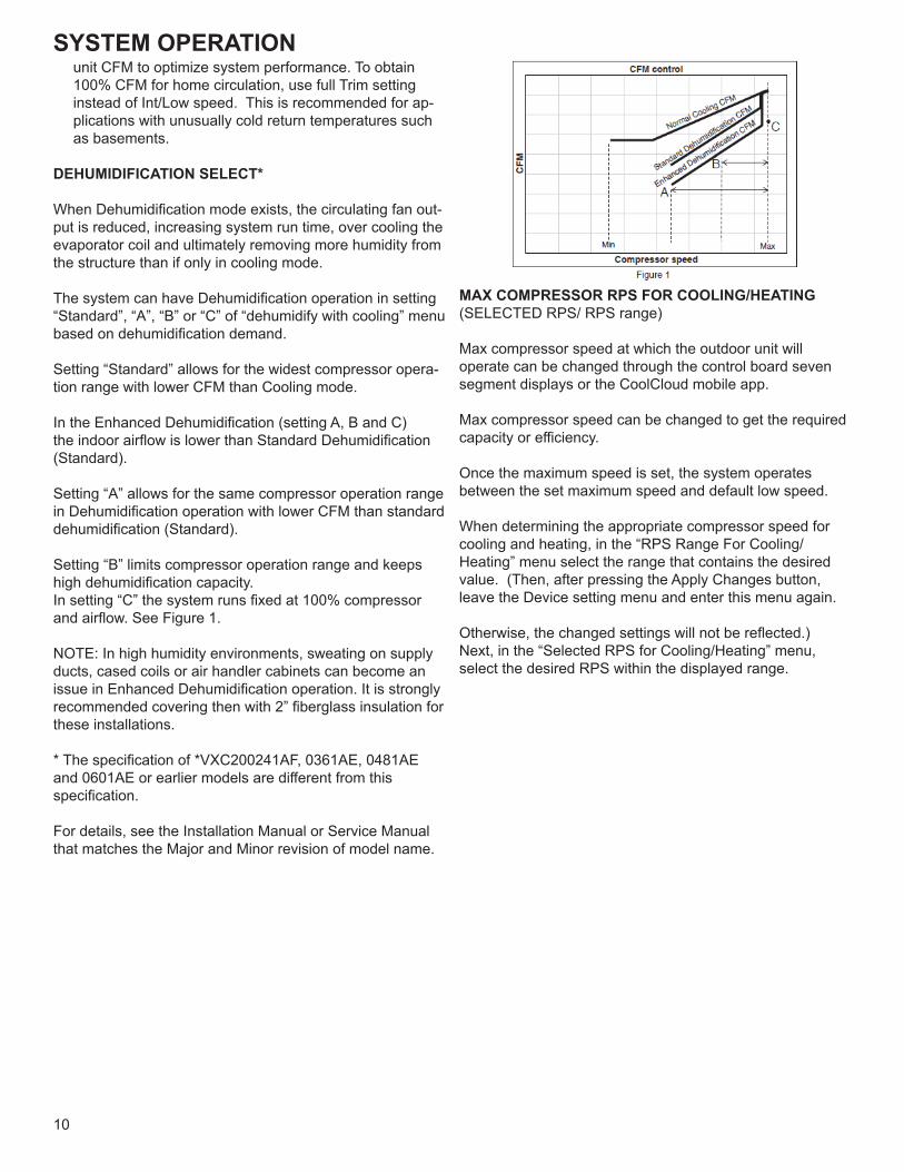
Setting “B” limits compressor operation range and keeps high dehumidification capacity.In setting “C” the system runs fixed at 100% compressor and airflow. See Figure 1.
NOTE: In high humidity environments, sweating on supply ducts, cased coils or air handler cabinets can become an issue in Enhanced Dehumidification operation. It is strongly recommended covering then with 2” fiberglass insulation for these installations.
* The specification of *VXC200241AF, 0361AE, 0481AE and 0601AE or earlier models are different from this specification.
For details, see the Installation Manual or Service Manual that matches the Major and Minor revision of model name.
MAX COMPRESSOR RPS FOR COOLING/HEATING(SELECTED RPS/ RPS range)
Max compressor speed at which the outdoor unit will operate can be changed through the control board seven segment displays or the CoolCloud mobile app.
Max compressor speed can be changed to get the required capacity or efficiency.
Once the maximum speed is set, the system operates between the set maximum speed and default low speed.
When determining the appropriate compressor speed for cooling and heating, in the “RPS Range For Cooling/ Heating” menu select the range that contains the desired value. (Then, after pressing the Apply Changes button, leave the Device setting menu and enter this menu again.
Otherwise, the changed settings will not be reflected.)Next, in the “Selected RPS for Cooling/Heating” menu, select the desired RPS within the displayed range.
SYSTEM OPERATION
11
COOLING CYCLE
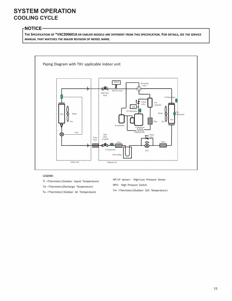
THE SPECIFICATION OF *VXC200601A OR EARLIER MODELS ARE DIFFERENT FROM THIS SPECIFICATION. FOR DETAILS, SEE THE SERVICEMANUAL THAT MATCHES THE MAJOR REVISION OF MODEL NAME.
NOTICE
LEGEND:
Tl =Thermistor( Outdoor Liquid Temperature)
Td =Thermistor(Discharge Temperature)
Ta =Thermistor( Outdoor Air Temperature)
HP/LP sensor= High/Low Pressure Sensor
HPS= High Pressure Switch
Tm =Thermistor(Outdoor Coil Temperature)
Piping Diagram with TXV applicable indoor unit
HexFan
Motor
Filterdryer
StopValve
(Liquid)
Ball Valve(Gas)
Fan
MotorHex
HP/LP
HP/LPs ensor
TmThermistor
Ref cooling
Ta Thermistor
Outdooru nitIndoor unit
TXV
Checkvalve
Td Thermistor
Filter
Compressor
Capillaryt ube
HPS
Oilseparator
Accumulator
T Thermistor
ReversingValve
Checkvalve
EEV
FilterFilter
SYSTEM OPERATION
12
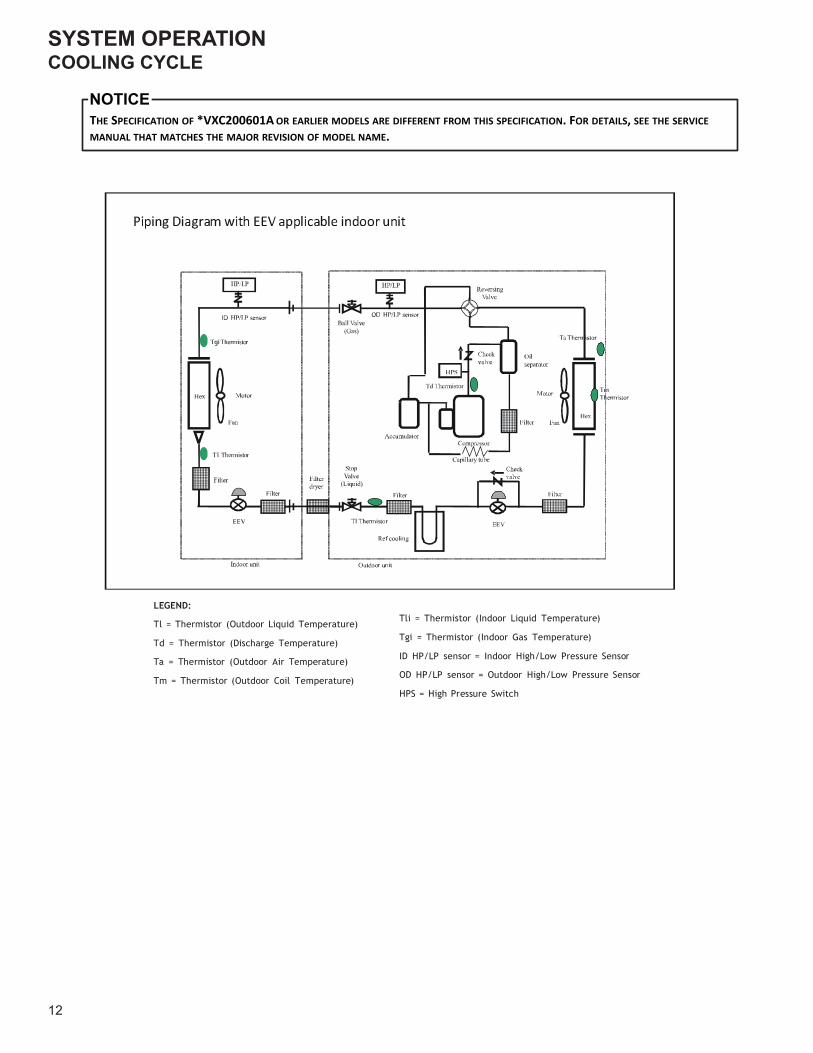
COOLING CYCLE
LEGEND:
Tl = Thermistor (Outdoor Liquid Temperature)
Td = Thermistor (Discharge Temperature)
Ta = Thermistor (Outdoor Air Temperature)
Tm = Thermistor (Outdoor Coil Temperature)
Tli = Thermistor (Indoor Liquid Temperature)
Tgi = Thermistor (Indoor Gas Temperature)
ID HP/LP sensor = Indoor High/Low Pressure Sensor
OD HP/LP sensor = Outdoor High/Low Pressure Sensor
HPS = High Pressure Switch
THE SPECIFICATION OF *VXC200601A OR EARLIER MODELS ARE DIFFERENT FROM THIS SPECIFICATION. FOR DETAILS, SEE THE SERVICEMANUAL THAT MATCHES THE MAJOR REVISION OF MODEL NAME.
NOTICE
SERVICING
13
CHECKING VOLTAGE
1. Remove outer case, control panel cover, etc., from unit being tested.
With power ON:
LINE VOLTAGE NOW PRESENT.
WARNING
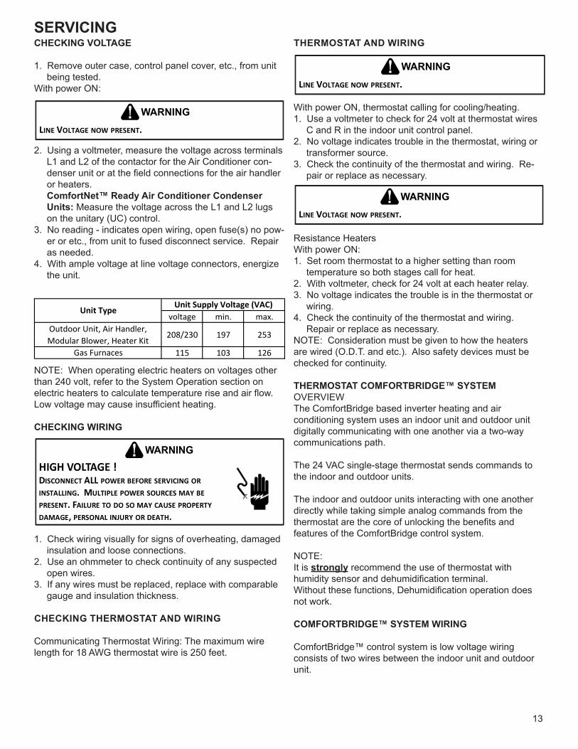
2. Using a voltmeter, measure the voltage across terminals L1 and L2 of the contactor for the Air Conditioner con-denser unit or at the field connections for the air handler or heaters. ComfortNet™ Ready Air Conditioner Condenser Units: Measure the voltage across the L1 and L2 lugs on the unitary (UC) control.
3. No reading - indicates open wiring, open fuse(s) no pow-er or etc., from unit to fused disconnect service. Repair as needed.
4. With ample voltage at line voltage connectors, energize the unit.
voltage min. max.Outdoor Unit, Air Handler,Modular Blower, Heater Kit 208/230 197 253
Gas Furnaces 115 103 126
Unit Supply Voltage (VAC)Unit Type
NOTE: When operating electric heaters on voltages other than 240 volt, refer to the System Operation section on electric heaters to calculate temperature rise and air flow. Low voltage may cause insufficient heating.
CHECKING WIRING
HIGH VOLTAGE !DISCONNECT ALL POWER BEFORE SERVICING OR INSTALLING. MULTIPLE POWER SOURCES MAY BE PRESENT. FAILURE TO DO SO MAY CAUSE PROPERTY DAMAGE, PERSONAL INJURY OR DEATH.
WARNING
1. Check wiring visually for signs of overheating, damaged insulation and loose connections.
2. Use an ohmmeter to check continuity of any suspected open wires.
3. If any wires must be replaced, replace with comparable gauge and insulation thickness.
CHECKING THERMOSTAT AND WIRING
Communicating Thermostat Wiring: The maximum wire length for 18 AWG thermostat wire is 250 feet.
THERMOSTAT AND WIRING
LINE VOLTAGE NOW PRESENT.
WARNING
With power ON, thermostat calling for cooling/heating.1. Use a voltmeter to check for 24 volt at thermostat wires
C and R in the indoor unit control panel.2. No voltage indicates trouble in the thermostat, wiring or
transformer source.3. Check the continuity of the thermostat and wiring. Re-
pair or replace as necessary.
LINE VOLTAGE NOW PRESENT.
WARNING
Resistance HeatersWith power ON:1. Set room thermostat to a higher setting than room
temperature so both stages call for heat.2. With voltmeter, check for 24 volt at each heater relay.3. No voltage indicates the trouble is in the thermostat or
wiring.4. Check the continuity of the thermostat and wiring.
Repair or replace as necessary.NOTE: Consideration must be given to how the heaters are wired (O.D.T. and etc.). Also safety devices must be checked for continuity.
THERMOSTAT COMFORTBRIDGE™ SYSTEMOVERVIEWThe ComfortBridge based inverter heating and airconditioning system uses an indoor unit and outdoor unitdigitally communicating with one another via a two-waycommunications path.
The 24 VAC single-stage thermostat sends commands tothe indoor and outdoor units.
The indoor and outdoor units interacting with one anotherdirectly while taking simple analog commands from thethermostat are the core of unlocking the benefits andfeatures of the ComfortBridge control system.
NOTE:It is strongly recommend the use of thermostat withhumidity sensor and dehumidification terminal.Without these functions, Dehumidification operation doesnot work.
COMFORTBRIDGE™ SYSTEM WIRING
ComfortBridge™ control system is low voltage wiringconsists of two wires between the indoor unit and outdoorunit.
SERVICING
14
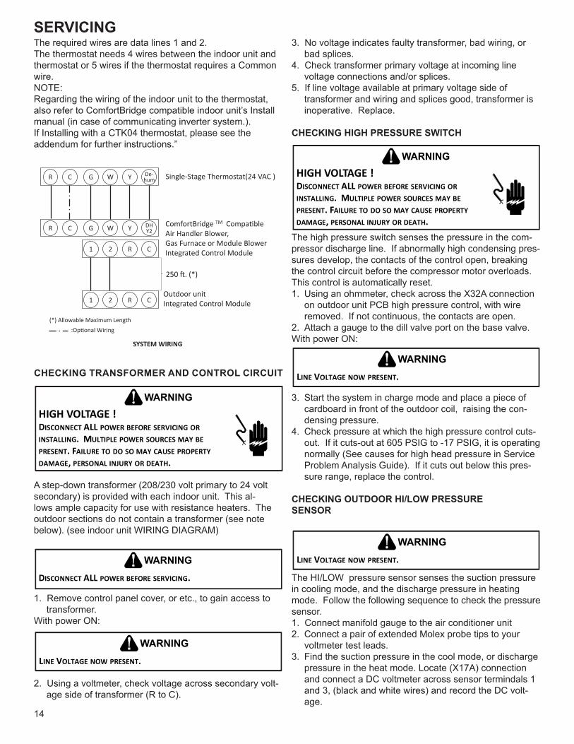
The required wires are data lines 1 and 2.The thermostat needs 4 wires between the indoor unit andthermostat or 5 wires if the thermostat requires a Commonwire.NOTE:Regarding the wiring of the indoor unit to the thermostat,also refer to ComfortBridge compatible indoor unit’s Installmanual (in case of communicating inverter system.).If Installing with a CTK04 thermostat, please see theaddendum for further instructions.”
1 2 R C
ComfortBridge TM Compa�bleAir Handler Blower,Gas Furnace or Module BlowerIntegrated Control Module
(*) Allowable Maximum Length
Outdoor unit Integrated Control Module
250 �. (*)
1 2 R C
SYSTEM WIRING
G W Y DHY2R C
Single-Stage Thermostat(24 VAC )G W Y De-humR C
:Op�onal Wiring
CHECKING TRANSFORMER AND CONTROL CIRCUIT
HIGH VOLTAGE !DISCONNECT ALL POWER BEFORE SERVICING OR INSTALLING. MULTIPLE POWER SOURCES MAY BE PRESENT. FAILURE TO DO SO MAY CAUSE PROPERTY DAMAGE, PERSONAL INJURY OR DEATH.
WARNING
A step-down transformer (208/230 volt primary to 24 volt secondary) is provided with each indoor unit. This al-lows ample capacity for use with resistance heaters. The outdoor sections do not contain a transformer (see note below). (see indoor unit WIRING DIAGRAM)
DISCONNECT ALL POWER BEFORE SERVICING.
WARNING
1. Remove control panel cover, or etc., to gain access to transformer.
With power ON:
LINE VOLTAGE NOW PRESENT.
WARNING
2. Using a voltmeter, check voltage across secondary volt-age side of transformer (R to C).
3. No voltage indicates faulty transformer, bad wiring, or bad splices.
4. Check transformer primary voltage at incoming line voltage connections and/or splices.
5. If line voltage available at primary voltage side of transformer and wiring and splices good, transformer is inoperative. Replace.
CHECKING HIGH PRESSURE SWITCH
HIGH VOLTAGE !DISCONNECT ALL POWER BEFORE SERVICING OR INSTALLING. MULTIPLE POWER SOURCES MAY BE PRESENT. FAILURE TO DO SO MAY CAUSE PROPERTY DAMAGE, PERSONAL INJURY OR DEATH.
WARNING
The high pressure switch senses the pressure in the com-pressor discharge line. If abnormally high condensing pres-sures develop, the contacts of the control open, breaking the control circuit before the compressor motor overloads. This control is automatically reset.1. Using an ohmmeter, check across the X32A connection
on outdoor unit PCB high pressure control, with wire removed. If not continuous, the contacts are open.
2. Attach a gauge to the dill valve port on the base valve.With power ON:
LINE VOLTAGE NOW PRESENT.
WARNING
3. Start the system in charge mode and place a piece of cardboard in front of the outdoor coil, raising the con-densing pressure.
4. Check pressure at which the high pressure control cuts-out. If it cuts-out at 605 PSIG to -17 PSIG, it is operating normally (See causes for high head pressure in Service Problem Analysis Guide). If it cuts out below this pres-sure range, replace the control.
CHECKING OUTDOOR HI/LOW PRESSURE SENSOR
LINE VOLTAGE NOW PRESENT.
WARNING
The HI/LOW pressure sensor senses the suction pressure in cooling mode, and the discharge pressure in heating mode. Follow the following sequence to check the pressure sensor. 1. Connect manifold gauge to the air conditioner unit2. Connect a pair of extended Molex probe tips to your
voltmeter test leads.3. Find the suction pressure in the cool mode, or discharge
pressure in the heat mode. Locate (X17A) connection and connect a DC voltmeter across sensor termindals 1 and 3, (black and white wires) and record the DC volt-age.
SERVICING
15
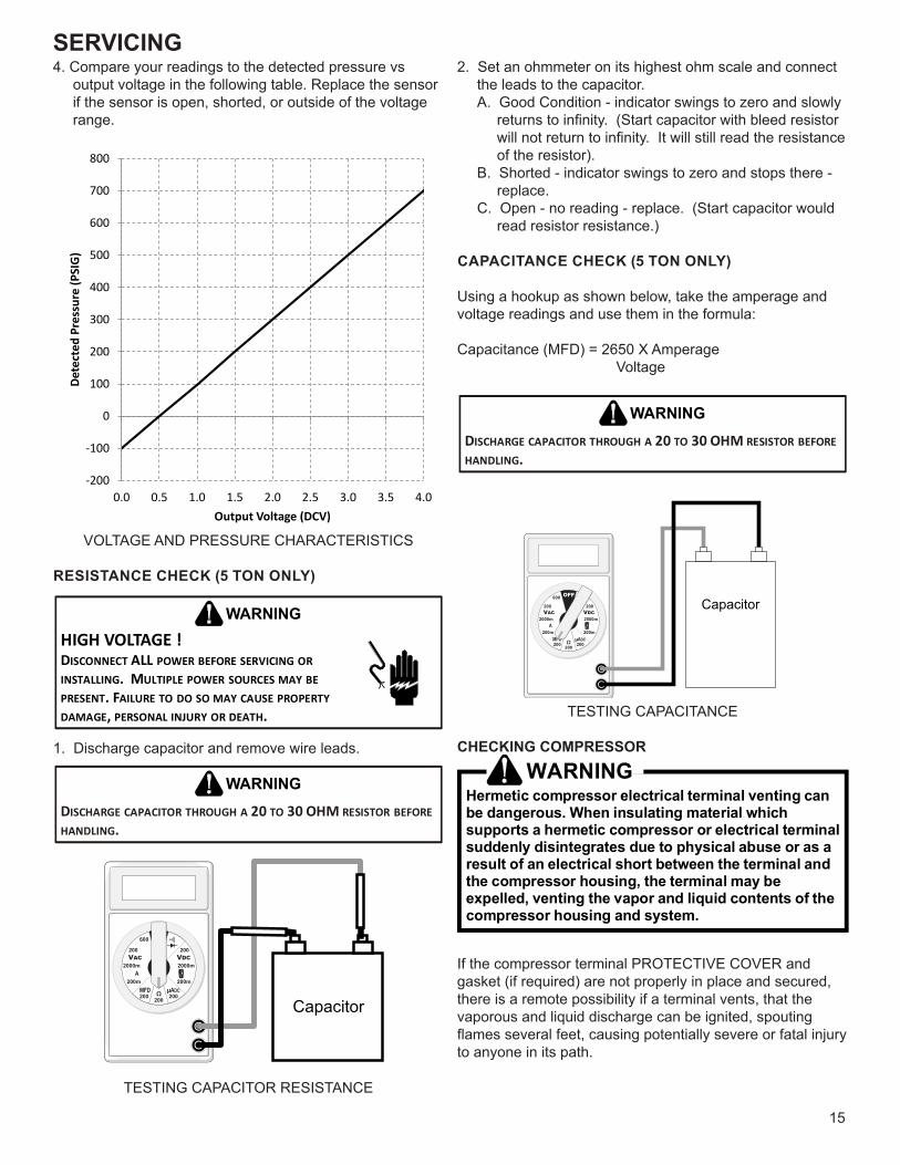
4. Compare your readings to the detected pressure vs output voltage in the following table. Replace the sensor if the sensor is open, shorted, or outside of the voltage range.
-200
-100
0
100
200
300
400
500
600
700
800
0.0 0.5 1.0 1.5 2.0 2.5 3.0 3.5 4.0
Dete
cted
Pre
ssur
e (P
SIG
)
Output Voltage (DCV)
VOLTAGE AND PRESSURE CHARACTERISTICS
RESISTANCE CHECK (5 TON ONLY)
HIGH VOLTAGE !DISCONNECT ALL POWER BEFORE SERVICING OR INSTALLING. MULTIPLE POWER SOURCES MAY BE PRESENT. FAILURE TO DO SO MAY CAUSE PROPERTY DAMAGE, PERSONAL INJURY OR DEATH.
WARNING
1. Discharge capacitor and remove wire leads.
DISCHARGE CAPACITOR THROUGH A 20 TO 30 OHM RESISTOR BEFORE HANDLING.
WARNING
Capacitor
TESTING CAPACITOR RESISTANCE
2. Set an ohmmeter on its highest ohm scale and connect the leads to the capacitor.A. Good Condition - indicator swings to zero and slowly
returns to infinity. (Start capacitor with bleed resistor will not return to infinity. It will still read the resistance of the resistor).
B. Shorted - indicator swings to zero and stops there - replace.
C. Open - no reading - replace. (Start capacitor would read resistor resistance.)
CAPACITANCE CHECK (5 TON ONLY)
Using a hookup as shown below, take the amperage and voltage readings and use them in the formula:
Capacitance (MFD) = 2650 X Amperage Voltage
DISCHARGE CAPACITOR THROUGH A 20 TO 30 OHM RESISTOR BEFORE HANDLING.
WARNING
Capacitor
TESTING CAPACITANCE
CHECKING COMPRESSOR
WARNINGHermetic compressor electrical terminal venting canbe dangerous. When insulating material whichsupports a hermetic compressor or electrical terminalsuddenly disintegrates due to physical abuse or as aresult of an electrical short between the terminal andthe compressor housing, the terminal may beexpelled, venting the vapor and liquid contents of thecompressor housing and system.
If the compressor terminal PROTECTIVE COVER and gasket (if required) are not properly in place and secured, there is a remote possibility if a terminal vents, that the vaporous and liquid discharge can be ignited, spouting flames several feet, causing potentially severe or fatal injury to anyone in its path.
SERVICING
16
This discharge can be ignited external to the compressor if the terminal cover is not properly in place and if the discharge impinges on a sufficient heat source.
Ignition of the discharge can also occur at the venting terminal or inside the compressor, if there is sufficient contaminant air present in the system and an electrical arc occurs as the terminal vents.
Ignition cannot occur at the venting terminal without the presence of contaminant air, and cannot occur externally from the venting terminal without the presence of an external ignition source.
Therefore, proper evacuation of a hermetic system is essential at the time of manufacture and during servicing.To reduce the possibility of external ignition, all open flame, electrical power, and other heat sources should be extinguished or turned off prior to servicing a system.
COMPRESSOR WINDING INSULATION TEST
The Inverter on the outdoor control board takes the position signal from the UVW line, connected with the compressor. If the system detects a malfunction on the compressor, check the insulation resistance in accordance with the fol-lowing procedure.
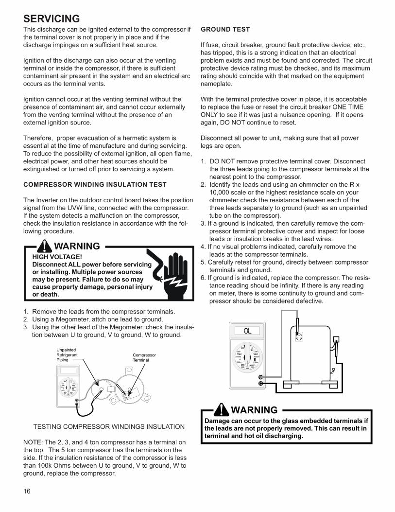
HIGH VOLTAGE!Disconnect ALL power before servicingor installing. Multiple power sourcesmay be present. Failure to do so maycause property damage, personal injuryor death.
1. Remove the leads from the compressor terminals.2. Using a Megometer, attch one lead to ground.3. Using the other lead of the Megometer, check the insula-
tion between U to ground, V to ground, W to ground.
Compressor Terminal
UnpaintedRefrigerantPiping
TESTING COMPRESSOR WINDINGS INSULATION
NOTE: The 2, 3, and 4 ton compressor has a terminal on the top. The 5 ton compressor has the terminals on the side. If the insulation resistance of the compressor is less than 100k Ohms between U to ground, V to ground, W to ground, replace the compressor.
GROUND TEST
If fuse, circuit breaker, ground fault protective device, etc., has tripped, this is a strong indication that an electrical problem exists and must be found and corrected. The circuit protective device rating must be checked, and its maximum rating should coincide with that marked on the equipment nameplate.
With the terminal protective cover in place, it is acceptable to replace the fuse or reset the circuit breaker ONE TIME ONLY to see if it was just a nuisance opening. If it opens again, DO NOT continue to reset.
Disconnect all power to unit, making sure that all power legs are open.
1. DO NOT remove protective terminal cover. Disconnect the three leads going to the compressor terminals at the nearest point to the compressor.
2. Identify the leads and using an ohmmeter on the R x 10,000 scale or the highest resistance scale on your ohmmeter check the resistance between each of the three leads separately to ground (such as an unpainted tube on the compressor).
3. If a ground is indicated, then carefully remove the com-pressor terminal protective cover and inspect for loose leads or insulation breaks in the lead wires.
4. If no visual problems indicated, carefully remove the leads at the compressor terminals.
5. Carefully retest for ground, directly between compressor terminals and ground.
6. If ground is indicated, replace the compressor. The resis-tance reading should be infinity. If there is any reading on meter, there is some continuity to ground and com-pressor should be considered defective.
OL
WARNINGDamage can occur to the glass embedded terminals ifthe leads are not properly removed. This can result interminal and hot oil discharging.
SERVICING
17
TESTING CRANKCASE HEATER (5TON ONLY)
The crankcase heater must be energized a minimum of 2 hours before the unit is operated. Crankcase heaters are used to prevent migration or accumulation of refrigerant in the compressor crankcase during the off cycles and pre-vents liquid slugging or oil pumping on start up. A crankcase heater will not prevent compressor damage due to a flood-back or over charge condition.
WARNINGDisconnect ALL power before servicing.
1. Disconnect the heater lead in wires.2. Using an ohmmeter, check heater continuity - should
test continuous. If not, replace.
NOTE: The positive temperature coefficient crankcase heater is a 33 watt 240 voltage heater. The cool resistance of the heater will be approximately 1745 ohms. The resis-tance will become greater as the temperature of the com-pressor shell increases.
TESTING TEMPERATURE SENSORS AND EEV COIL RESISTANCE
The *VXC20 outdoor units and AVPEC* indoor units are factory equipped with:• (Ta) an outdoor air temperature sensor• (Tm) an outdoor coil temperature sensor• (TI) an outdoor liquid temperature sensor• (Td) a discharge temperature sensor• (Tgi) an indoor gas temperature sensor• (Tli) an indoor liquid temperature sensor
To check above sensors:
HIGH VOLTAGE!Disconnect ALL power before servicingor installing. Multiple power sourcesmay be present. Failure to do so maycause property damage, personal injuryor death.
1. Disconnect power to the Air Conditioner condensor.2. Disconnect the sensor from the electric board.3. Connect an ohmmeter across the sensor terminals. The
ohmmeter should read be the resistance shown in the table THERMISTOR RESISTANCE AND TEMPERA-TURE CHARACTERISTICS CHART (page 31). Replace the sensor if the sensor is open, shorted, or outside the valid resistance range.
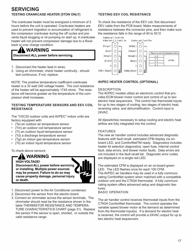
TESTING EEV COIL RESISTANCE
To check the resistance of the EEV coil, first disconnect EEV cable from the PCB board. Make measurements of resistance between the connector pins, and then make sure the resistance falls in the range of 40 to 50 Ʊ.
AVPEC HEATER CONTROL (OPTIONAL)
DESCRIPTIONThe AVPEC models utilize an electronic control that pro-vides ECM blower motor control and control of up to two electric heat sequencers. The control has thermostat inputs for up to two stages of cooling, two stages of electric heat, reversing valve, and dehumidification. Control input is 24VAC.
All dipswitches necessary to setup cooling and electric heat airflow are fully integrated into the control.
FEATURESThe new air handler control includes advanced diagnostic features with fault recall, estimated CFM display via on-board LED, and ComfortNetTM ready. Diagnostics includes heater kit selection diagnostics, open fuse, internal control fault, data errors, and blower motor faults. Data errors are not included in the fault recall list. Diagnostic error codes are displayed on a single red LED.
The estimated CFM is displayed on an on-board green LED. The LED flashes once for each 100 CFM.The AVPEC air handlers may be used in a fully communi-cating ComfortNet system when matched with a compatible outdoor unit and the CTK04 thermostat. A fully communi-cating system offers advanced setup and diagnostic fea-tures.BASIC OPERATION
The air handler control receives thermostat inputs from the CTK04 ComfortNet thermostat. The control operates the variable speed blower motor at the demand as determined from the thermostat input(s). If a demand for electric heat is received, the control will provide a 24VAC output for up to two electric heat sequencers.
SERVICING
18
TROUBLESHOOTING
MOTOR CONTROL CIRCUITS
HIGH VOLTAGE!Disconnect ALL power before servicingor installing. Multiple power sourcesmay be present. Failure to do so maycause property damage, personal injuryor death.
1. Turn on power to air handler or modular.
WARNINGLine Voltage now present.
2. Check voltage between pins 1 and 4 at the 4-wire motor connector on the control board. Voltage should be between 9 and 15 VDC. Replace control if voltage is not as specified.
ELECTRIC HEAT SEQUENCER OUTPUTS
HIGH VOLTAGE!Disconnect ALL power before servicingor installing. Multiple power sourcesmay be present. Failure to do so maycause property damage, personal injuryor death.
1. Turn on power to air handler or modular blower.
WARNINGLine Voltage now present.
2. Disconnect the 4-circuit harness connecting the control to the electric heater kit.
3. Provide a thermostat demand for low stage auxiliary heat. Measure the voltage between pins 1 and 3 at the onboard electric heat connector. Voltage should mea-sure 24VAC. Replace control if no voltage is present.
NOTE: Allow for any built-in time delays before making voltage measurements. Any electric heater faults that are present may prevent the heater output from energizing. Ver-ify that no heater faults are present before making voltage measurements.
4. Provide a thermostat demand for high stage auxiliary heat (W1 + W2). Measure the voltage between pins 1 and 3 at the on-board electric heat connector. Measure the voltage between pins 2 and 3 at the on-board electric heat connector. Voltage should measure 24VAC. Re-place control if no voltage is present.
Communications (Applies only to Systems with Compatible ComfortNetTM Outdoor Unit and CTK04AE* Thermostat)
The integrated air handler control has some on-board tools that may be used to troubleshoot the network. These tools are: red communications LED, green receive (Rx) LED, and learn button. These are described belowa. Red communications LED – Indicates the status of the
network. Refer to the Network Troubleshooting Chart for the LED status and the corresponding potential problem.
b. Green receive LED – Indicates network traffic. Refer to the Network Troubleshooting Chart for the LED status and the corresponding potential problem.
c. Learn button – Used to reset the network. Depress the button for approximately 2 seconds to reset the network.
For details, see NETWORK TROUBLSHOOTING section.
WARNINGDisconnect ALL power before servicing.
REFRIGERATION REPAIR PRACTICE
DANGERAlways remove the refrigerant charge in a propermanner before applying heat to the system.
When repairing the refrigeration system:
HIGH VOLTAGE!Disconnect ALL power before servicingor installing. Multiple power sourcesmay be present. Failure to do so maycause property damage, personal injuryor death.
1. Never open a system that is under vacuum. Air and moisture will be drawn in.
2. Plug or cap all openings.3. Remove all burrs and clean the brazing surfaces of the
tubing with sand cloth or paper. Brazing materials do not flow well on oxidized or oily surfaces.
4. Clean the inside of all new tubing to remove oils and pipe chips.
5. When brazing, sweep the tubing with dry nitrogen to prevent the formation of oxides on the inside surfaces.
6. Complete any repair by replacing the liquid line drier in the system, evacuate and charge.
BRAZING MATERIALS
Important note: Torch heat required to braze tubes of various sizes is proportional to the size of the tube. Tubes of smaller size require less heat to bring the tube to braz-ing temperature before adding brazing alloy. Applying too much heat to any tube can melt the tube. Service personnel must use the appropriate heat level for the size of the tube being brazed.
SERVICING
19
NOTE: The use of a heat shield when brazing is recom-mended to avoid burning the serial plate or the finish on the unit. Heat trap or wet rags should be used to protect heat sensitive components such as stop valves, EEV, TXV and filters.
Copper to Copper Joints - Sil-Fos used without flux (alloy of 15% silver, 80% copper, and 5% phosphorous). Recom-mended heat 1400°F.
Copper to Steel Joints - Silver Solder used without a flux (alloy of 30% silver, 38% copper, 32% zinc). Recommend-ed heat - 1200°F.
LEAK TESTING (NITROGEN OR NITROGEN-TRACED)
To avoid the risk of fire or explosion, never useoxygen, high pressure air or flammable gases for leaktesting of a refrigeration system.
WARNING
To avoid possible explosion, the line from thenitrogen cylinder must include a pressure regulatorand a pressure relief valve. The pressure relief valvemust be set to open at no more than 450 psig.
LEAK TESTING
Leak test the system using dry nitrogen and soapy water to identify leaks. If you prefer to use an electronic leak de-tector, charge the system to 10 PSIG with the appropriate system refrigerant (see Serial Data Plate for refrigerant identification). Do not use an alternative refrigerant. Using dry nitrogen finish charging the system to 450 PSIG. Apply the leak detector to all suspect areas. When leaks are discovered, repair the leaks, and repeat the pressure test. If leaks have been eliminated proceed to system evacuation.
STANDING PRESSURE TEST
Using dry nitrogen, pressurize the system to 450 PSIG. Allow the pressure to stabilize and hold for 15 minutes (min-imum). If the pressure does not drop below 450 PSIG the system is considered leak free. Proceed to system evacu-ation using the Deep Vacuum Method. If after 15 minutes the pressure drops below 450 PSIG follow the procedure outlined below to identify system leaks. Repeat the Stand-ing Pressure Test.
SYSTEM EVACUATION
WARNINGREFRIGERANT UNDER PRESSURE!Failure to follow proper procedures may causeproperty damage, personal injury or death.
IMPORTANT NOTE: Because of the potential damage to compressors, do not allow suction pressure at service valve to drop below 5 PSIG when pumping unit system down for repair. Outdoor section, depending on line set length and amount of charge in system, may not be able to hold the entire system charge.
This is the most important part of the entire service proce-dure. The life and efficiency of the equipment is dependent upon the thoroughness exercised by the serviceman when evacuating air (non-condensables) and moisture from the system.
Air in a system causes high condensing temperature and pressure, resulting in increased power input and reduced performance.
Moisture chemically reacts with the refrigerant oil to form corrosive acids. These acids attack motor windings and parts, causing breakdown.
The equipment required to thoroughly evacuate the system is a vacuum pump, capable of producing a vacuum equiva-lent to 500 microns absolute and a micron gauge to give a true reading of the vacuum in the system
NOTE: Never use the system compressor as a vacuum pump or run when under a high vacuum. Motor damage could occur.
Condensing unit liquid and suction valves are closed to con-tain the charge within the unit. The unit is shipped with the valve stems closed and caps installed. Do not open valves until the system is evacuated.
DEEP VACUUM METHOD
The Deep Vacuum Method requires a vacuum pump rated for 500 microns or less. This method is an effective and effi-cient way of assuring the system is free of non-condensable air and moisture. As an alternative, the Triple Evacuation Method may be used.
It is recommended to remove the Schrader Cores from the service valves using a core-removal tool to expedite the evacuation procedure.
Connect the vacuum pump, micron gauge, and vacuum rat-ed hoses to both service valves. Evacuation must use both service valves to eliminate system mechanical seals.Evacuate the system to less than 500 microns.Isolate the pump from the system and hold vacuum for
SERVICING
20
10 minutes (minimum). Typically, pressure will rise slowly during this period. If the pressure rises to less than 1000 microns and remains steady, the system is considered leak-free; proceed to system charging and startup.If pressure rises above 1000 microns but holds steady below 2000 microns, non-condensable air or moisture may remain or a small leak is present. Return to step 2: If the same result is achieved check for leaks and repair. Repeat the evacuation procedure.
If pressure rises above 2000 microns, a leak is present. Check for leaks and repair. Repeat the evacuation proce-dure
Triple Evacuation Method (Alternate to Deep Vacuum Method)
1. Evacuate the system to 4000 microns and hold for 15 minutes. Then, break the vacuum with dry nitrogen, bring the system pressure up to 2-3 PSIG, and hold for 20 minutes. Release the nitrogen.
2. Evacuate to 1500 microns and hold for 20 minutes. Break the vacuum with dry nitrogen again, bring the system pressure back up to 2-3 PSIG, and hold for 20 minutes.
3. Then, evacuate the system until it is below 500 microns and hold for 60 minutes.
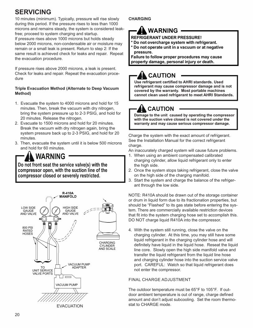
LOW SIDEGAUGE
AND VALVE
HIGH SIDEGAUGE
AND VALVE
TO UNIT SERVICEVALVE PORTS
VACUUM PUMP
VACUUM PUMPADAPTER
800 PSIRATEDHOSES
CHARGINGCYLINDER
AND SCALE
EVACUATION
CHARGING
WARNINGREFRIGERANT UNDER PRESSURE!* Do not overcharge system with refrigerant.* Do not operate unit in a vacuum or at negative pressure.Failure to follow proper procedures may causeproperty damage, personal injury or death.
CAUTIONUse refrigerant certified to AHRI standards. Used refrigerant may cause compressor damage and is not covered by the warranty. Most portable machinescannot clean used refrigerant to meet AHRI Standards.
CAUTIONDamage to the unit caused by operating the compressorwith the suction valve closed is not covered under thewarranty and may cause serious compressor damage.
Charge the system with the exact amount of refrigerant.See the Installation Manual for the correct refrigerant charge.An inaccurately charged system will cause future problems.1. When using an ambient compensated calibrated
charging cylinder, allow liquid refrigerant only to enter the high side.
2. Once the system stops taking refrigerant, close the valve on the high side of the charging manifold.
3. Start the system and charge the balance of the refriger-ant through the low side.
NOTE: R410A should be drawn out of the storage container or drum in liquid form due to its fractionation properties, but should be “Flashed” to its gas state before entering the sys-tem. There are commercially available restriction devices that fit into the system charging hose set to accomplish this. DO NOT charge liquid R410A into the compressor.
4. With the system still running, close the valve on the charging cylinder. At this time, you may still have some liquid refrigerant in the charging cylinder hose and will definitely have liquid in the liquid hose. Reseat the liquid line core. Slowly open the high side manifold valve and transfer the liquid refrigerant from the liquid line hose and charging cylinder hose into the suction service valve port. CAREFUL: Watch so that liquid refrigerant does not enter the compressor.
FINAL CHARGE ADJUSTMENT
The outdoor temperature must be 65°F to 105°F. If out-door ambient temperature is out of range, charge defined amount and don’t adjust subcooling. Set the room thermo-stat to CHARGE mode.
SERVICING
21
After system has stabilized per startup instructions, check subcooling as detailed in the following section.In the event of system overcharge or undercharge, refrig-erant in the system must be adjusted to the appropriate subcooling and superheat as specified in the following sections. Refrigerant amount should be adjusted within +/- 0.5 lb. if the outdoor ambient temperature is greater than 65°F and less than 105°F. Manufacturer recommends that the system should be evacuated and should be charged the initial refrigerant for given line length when the ambient temperature is less than 65°F and more than 105°F. Refer to the Installation Manual to calculate refrigerant amount.
5. With the system still running, remove hose and reinstall both valve caps.
6. Check system for leaks.
NOTE: Subcooling information is valid only while the unit is operating at 100% capacity or 100% of compressor speed in CHARGE MODE. Compressor speed is displayed under STATUS menu in the thermostat.
CHECKING COMPRESSOR EFFICIENCY
The reason for compressor inefficiency is that the com-pressor is broken or damaged, reducing the ability of the compressor to pump refrigerant vapor.The condition of the compressor is checked in the following manner.1. Attach gauges to the high and low side of the system.2. Start the system and run CHARGE MODE.If the test shows:a. Below normal high side pressure.b. Above normal low side pressure.c. Low temperature difference across coil.d. Low amp draw at compressor.And the charge is correct. The compressor is faulty - re-place the compressor.
THERMOSTATIC EXPANSION VALVEThe expansion valve is designed to control the rate of liquid refrigerant flow into an evaporator coil in exact proportion to the rate of evaporation of the refrigerant in the coil. The amount of refrigerant entering the coil is regulated since the valve responds to temperature of the refrigerant gas leaving the coil (feeler bulb contact) and the pressure of the refrig-erant in the coil. This regulation of the flow prevents the return of liquid refrigerant to the compressor. Some TXV valves contain an internal check valve thus eliminating the need for an external check valve and bypass loop. The three forces which govern the operation of the valve are: (1) the pressure created in the power assem-bly by the feeler bulb, (2) evaporator pressure, and (3) the equivalent pressure of the superheat spring in the valve.
0% bleed type expansion valves are used on indoor and outdoor coils. The 0% bleed valve will not allow the system pressures (High and Low side) to equalize during the shut down period. The valve will shut off completely at approxi-mately 100 PSIG.
30% bleed valves used on some other models will continue to allow some equalization even though the valve has shut-off completely because of the bleed holes within the valve. This type of valve should not be used as a replacement for a 0% bleed valve, due to the resulting drop in performance.
The bulb must be securely fastened with two straps to a clean straight section of the suction line. Application of the bulb to a horizontal run of line is preferred. If a vertical installation cannot be avoided, the bulb must be mounted so that the capillary tubing comes out at the top.
THE VALVES PROVIDED BY THE MANUFACTURER ARE DESIGNED TO MEET THE SPECIFICATION REQUIRE-MENTS FOR OPTIMUM PRODUCT OPERATION. DO NOT USE SUBSTITUTES.
OVERFEEDING
Overfeeding by the thermostatic expansion valve results in high suction pressure, cold suction line, and possible liquid slugging of the compressor.If these symptoms are observed:
1. Check for an overcharged unit by referring to the cooling performance charts in the servicing section.
2. Check the operation of the power element in the valve as explained in S-110 Checking Thermostatic Expansion Valve
3. Check for restricted or plugged equalizer tube.
UNDERFEEDING
Underfeeding by the thermostatic expansion valve results in low system capacity and low suction pressures.If these symptoms are observed:1. Check for a restricted liquid line or drier. A restriction will
be indicated by a temperature drop across the drier.2. Check the operation of the power element of the valve
as described in S-110 Checking Thermostatic Expansion Valve Operation.
SUPERHEAT
The thermostatic expansion valve is factory adjusted to maintain 8°F ± 1°F degrees superheat of the suction gas. Before checking the superheat or replacing the valve, perform all the procedures outlined under Air Flow, Refrig-erant Charge, Thermostatic Expansion Valve - Overfeeding, Underfeeding. These are the most common causes for evaporator malfunction.
SERVICING
22
CHECKING SUPERHEAT
Refrigerant gas is considered superheated when its tem-perature is higher than the saturation temperature corre-sponding to its pressure. The degree of superheat equals the degrees of temperature increase above the saturation temperature at existing pressure. See Temperature - Pres-sure Chart on following pages.
1. Run system at least 10 minutes to allow pressure to stabilize.
2. For best results, temporarily install a thermometer on the liquid line at the liquid line service valve and 4-6” from the compressor on the suction line. Ensure the thermom-eter makes adequate contact and is insulated for best possible readings. Use liquid line temperature to deter-mine sub-cooling and vapor temperature to determine superheat.
NOTE: An optional method is to locate the thermometer at the suction line service valve. Ensure the thermometer makes adequate contact and is insulated for best possible readings.
3. Refer to the superheat table provided for proper system superheat. Add charge to lower superheat or recover charge to raise superheat. Superheat Formula = Suct. Line Temp. - Sat. Suct. Temp. EXAMPLE:
a. Suction Pressure = 143 PSIG b. Corresponding Temp. = 50°F. c. Thermometer on Suction Line = 58°F.To obtain the degrees temperature of superheat, subtract 50.0 from 58.0°F.The difference is 8° Superheat. The 8° Superheat would fall in the ± range of allowable superheat.
CHECKING SUBCOOLING
Refrigerant liquid is considered subcooled when its tem-perature is lower than the saturation temperature corre-sponding to its pressure. The degree of subcooling equals the degrees of temperature decrease below the saturation temperature at the existing pressure.
1. Attach an accurate thermometer or preferably a thermo-couple type temperature tester to the liquid service valve as it leaves the condensing unit.
2. Install a high side pressure gauge on the high side (liq-uid) service valve at the front of the unit.
3. Record the gauge pressure and the temperature of the line.
4. Review the technical information manual or specification sheet for the model being serviced to obtain the design subcooling.
5. Compare the hi-pressure reading to the “Required Liquid Line Temperature” chart. Find the hi-pressure value on the left column. Follow that line right to the column under the design subcooling value. Where the two intersect is the required liquid line temperature.
Alternately you can convert the liquid line pressure gauge reading to temperature by finding the gauge read-ing in the R-410A Pressure vs. Temperature Chart, find the temperature in the °F. Column.
6. The difference between the thermometer reading and pressure to temperature conversion is the amount of subcooling.
Add charge to raise subcooling. Recover charge to lower subcooling.Subcooling Formula = Sat. Liquid Temp. - Liquid Line Temp.NOTE: To adjust subcooling, follow the sequence of S-108.
EXAMPLE: a. Liquid Line Pressure = 417 PSIG b. Corresponding Temp. = 120°F. c. Thermometer on Liquid line = 109°F.
To obtain the amount of subcooling subtract 109°F from 120°F.The difference is 11° subcooling. See the specification sheet or technical information manual for the design sub-cooling range for your unit.There are other causes for high head pressure which may be found in the “Cooling / Heating Analysis Chart.”If other causes check out normal, an overcharge or a sys-tem containing non-condensables would be indicated.If this system is observed:
1. Start the system.2. Remove and capture small quantities of gas from the
suction line dill valve until the head pressure is reduced to normal.
3. Observe the system while running a cooling perfor-mance test. If a shortage of refrigerant is indicated, then the system contains non-condensables.
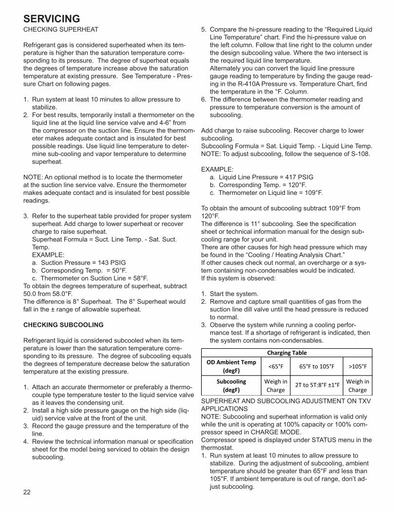
OD Ambient Temp(degF) <65°F 65°F to 105°F >105°F
Subcooling(degF)
Weigh in Charge
2T to 5T:8°F ±1°F Weigh inCharge
Charging Table
SUPERHEAT AND SUBCOOLING ADJUSTMENT ON TXV APPLICATIONSNOTE: Subcooling and superheat information is valid only while the unit is operating at 100% capacity or 100% com-pressor speed in CHARGE MODE.Compressor speed is displayed under STATUS menu in the thermostat.1. Run system at least 10 minutes to allow pressure to
stabilize. During the adjustment of subcooling, ambient temperature should be greater than 65°F and less than 105°F. If ambient temperature is out of range, don’t ad-just subcooling.

SERVICING
23
2. For best results, temporarily install a thermometer on the liquid line at the liquid line service valve and 4-6” from the compressor on the suction line. Ensure the thermom-eter makes adequate contact and is insulated for best possible readings. Use liquid line temperature to deter-mine sub-cooling and vapor temperature to determine superheat.
NOTE: An optional method is to locate the thermometer at the suction line service valve. Ensure the thermometer makes adequate contact and is insulated for best possi-ble readings.
3. The system subcooling should be 8°F ± 1°F(*1). If not in that range, adjust subcooling and superheat according to the following procedure.a. If subcooling and superheat are low, adjust TXV to 7
to 9°F superheat, then check subcooling. NOTE: To adjust superheat, turn the valve stem
clockwise to increase and counter clockwise to de-crease.
b. If subcooling is low and superheat is 7 to 9°F, add charge to rise subcooling to 8°F ± 1°F(*1), then check superheat.
c.If subcooling is low and superheat is high, add charge to rise subcooling to 8°F ± 1°F(*1), then check super-heat.
d. If subcooling is 8°F ± 1°F(*1) and superheat is high, adjust the TXV valve to 7 to 9°F superheat, then check subcooling.
e. If subcooling and superheat are high, adjust the TXV valve to 7 to 9°F superheat, then check subcooling.
f. If subcooling is high and superheat is 7 to 9°F, re-move charge to lower the subcooling to 8°F ± 1°F(*1), then check superheat.
g. If subcooling is high and superheat is low, adjust the TXV valve to 7 to 9°F superheat and remove charge to low the subcooling to 8°F ± 1°F(*1).
h. If subcooling is 8°F ± 1°F(*1) and superheat is low, adjust the TXV valve to 7 to 9°F superheat and re-move charge to lower the subcooling 8°F ± 1°F(*1), then check the superheat.
*1.10°F ± 1°F only for *VXC20060**NOTE: It is recommended to add charge in 4 oz. increments each time to achieve the target subcooling.4. Disconnect manifold set. Installation is complete.
SUBCOOLING ADJUSTMENT ON EEV APPLICATIONS
NOTE: Subcooling information is valid only while the unit isoperating at 100% capacity or 100% compressor speed in CHARGE MODE.
Compressor speed is displayed under STATUS menu in thethermostat.
1. Run system at least 20 minutes to allow pressure to stabilize. During the adjustment of subcooling, ambient temperature should be greater than 65°F and less than 105°F. If ambient temperature is out of range, don’t ad-
just
subcooling.2. For best results, temporarily install a thermometer on the liquid line at the liquid line service valve. Ensure the thermometer makes adequate contact and is insulated
for best possible readings. Use liquid line temperature to determine sub-cooling.3. The system subcooling should fall in the range shown in following table. If not in that range, adjust subcooling according to the following procedure.
a. If subcooling is low, add charge to adjust the subcool-ing to 8°F ± 1°F(*1).
b. If subcooling is high, remove charge to lower the subcooling to specified range.
*1.10°F ± 1°F only for *VXC20060**
NOTE: It is recommended to add charge in 4 oz. increments each time to achieve the target subcooling.
4. Disconnect manifold set. Installation is complete.
CHECKING THERMOSTATIC EXPANSION VALVE OPERATION
1. Remove the remote bulb of the thermostatic expansion valve from the suction line.
2. Start the system and cool the bulb in a container of ice water, closing the valve. As you cool the bulb, the suc-tion pressure should fall and the suction temperature will rise.
3. Next warm the bulb in your hand. As you warm the bulb, the suction pressure should rise and the suction tem-perature will fall.
4. If a temperature or pressure change is noticed, the expansion valve is operating. If no change is noticed, the valve is restricted, the power element is faulty, or the equalizer tube is plugged.
5. Capture the charge, replace the valve and drier, evacu-ate and recharge.
NON-CONDENSABLES
If non-condensables are suspected, shut down the sys-tem and allow the pressures to equalize. Wait at least 15 minutes. Compare the pressure to the temperature of the coldest coil since this is where most of the refrigerant will be. If the pressure indicates a higher temperature than that of the coil temperature, non-condensables are present.
Non-condensables are removed from the system by first removing the refrigerant charge, replacing and/or installing liquid line drier, evacuating and recharging.
COMPRESSOR BURNOUT
When a compressor burns out, high temperature develops causing the refrigerant, oil and motor insulation to decom-pose forming acids and sludge.
SERVICING
24
If a compressor is suspected of being burned-out, attach a refrigerant hose to the liquid line dill valve and properly remove and dispose of the refrigerant.
NOTICEViolation of EPA regulations may result in finesor other penalties.
Now determine if a burn out has actually occurred. Confirm by analyzing an oil sample using a Sporlan Acid Test Kit, AK-3 or its equivalent.
Remove the compressor and obtain an oil sample from the suction stub. If the oil is not acidic, either a burnout has not occurred or the burnout is so mild that a complete clean-up is not necessary.
If acid level is unacceptable, the system must be cleaned by using the clean-up drier method.
CAUTIONDo not allow the sludge or oil to contact the skin.Severe burns may result.
NOTE: The Flushing Method using R-11 refrigerant is no longer approved by Daikin Brand Heating-Cooling.
REFRIGERANT PIPING
The piping of a refrigeration system is very important in relation to system capacity, proper oil return to compressor, pumping rate of compressor and cooling performance of the evaporator. A bi-flow filter drier must be brazed on by the installer onsite. Ensure the bi-flow filter drier pain finish is intact after brazing. If the paint of the steel filter drier has been burned or chipped, repaint or treat with a rust preven-tative. The recommended location of the filter drier is be-fore the expansion device at the indoor unit. The liquid line must be insulated if more han 50 ft. of liquid line will pass through an area that may reach temperatures of 30° F of higher than ambient in cooling mode and/or if the tempera-ture inside the conditioned space may reach a temperature lower than ambient in heating mode. FVC oils maintain a consistent viscosity over a large temperature range which aids in the oil return to the compressor; however, there will be some installations which require oil return traps. These installations should be avoided whenever possible, as adding oil traps to the refrigerant lines also increases the opportunity for debris and moisture to be introduced into the system. Avoid long running traps in horizontal suction line.
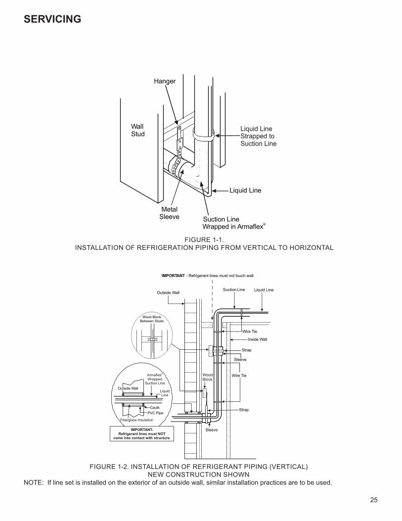
SERVICING
25
Liquid Line
Suction LineWrapped in Armaflex®
MetalSleeve
Hanger
WallStud
Liquid LineStrapped toSuction Line
FIGURE 1-1.INSTALLATION OF REFRIGERATION PIPING FROM VERTICAL TO HORIZONTAL
Outside Wall
Inside Wall
Liquid LineSuction Line
IMPORTANT - Refrigerant lines must not touch wall.
Strap
Sleeve
Strap
Sleeve
Wire Tie
Wire Tie
PVC PipeCaulk
Outside Wall
ArmaflexWrapped
Suction Line
®
LiquidLine
Wood BlockBetween Studs
IMPORTANT:Refrigerant lines must NOT
come into contact with structure.
Fiberglass Insulation
WoodBlock
FIGURE 1-2. INSTALLATION OF REFRIGERANT PIPING (VERTICAL)NEW CONSTRUCTION SHOWN
NOTE: If line set is installed on the exterior of an outside wall, similar installation practices are to be used.
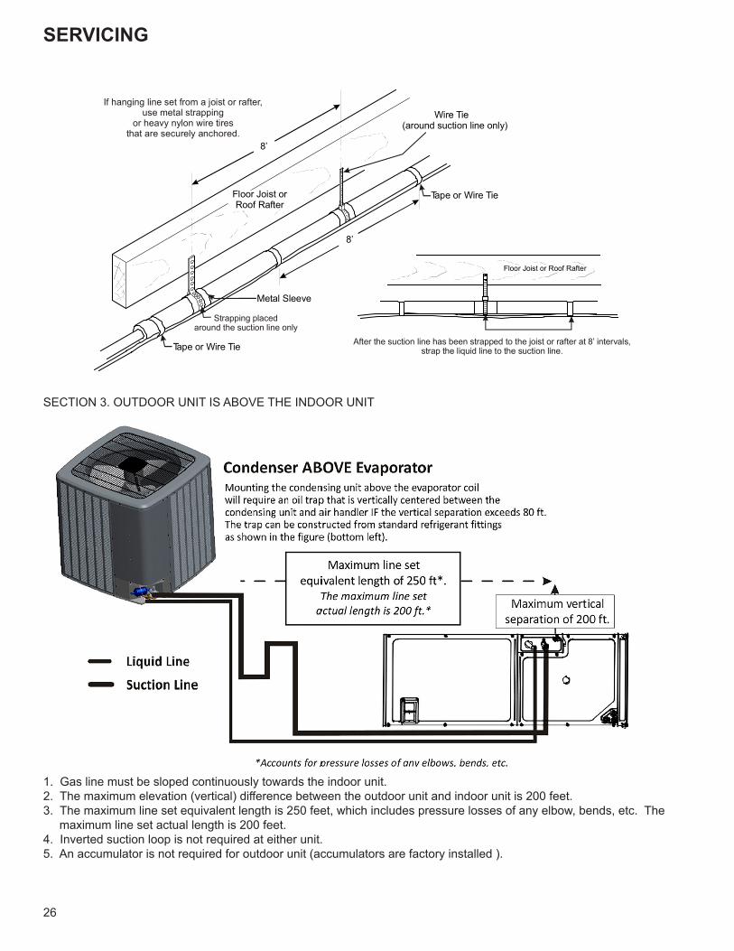
SERVICING
26
Floor Joist or Roof Rafter
After the suction line has been strapped to the joist or rafter at 8’ intervals,strap the liquid line to the suction line.
8’
Metal Sleeve
Wire Tie(around suction line only)
Floor Joist orRoof Rafter
Tape or Wire Tie
Tape or Wire Tie
8’
If hanging line set from a joist or rafter,use metal strapping
or heavy nylon wire tiresthat are securely anchored.
Strapping placedaround the suction line only
SECTION 3. OUTDOOR UNIT IS ABOVE THE INDOOR UNIT
1. Gas line must be sloped continuously towards the indoor unit.2. The maximum elevation (vertical) difference between the outdoor unit and indoor unit is 200 feet.3. The maximum line set equivalent length is 250 feet, which includes pressure losses of any elbow, bends, etc. The
maximum line set actual length is 200 feet.4. Inverted suction loop is not required at either unit.5. An accumulator is not required for outdoor unit (accumulators are factory installed ).

SERVICING
27
SECTION 4. OUTDOOR UNIT IS BELOW THE INDOOR UNIT
1. The maximum elevation (vertical) difference between the outdoor unit and the indoor unit is 90 feet.2. Suction line must be installed in a manner to prevent liquid migration to the outdoor unit from the indoor unit.The Air Conditioner condenser unit is shipped with a predetermined factory charge level as shown in the following chart. For longer line sets greater than 15 feet, add 0.6 ounces of refrigernat per foot.
Oil Trap Construction
45°ELL
SHORT RADIUSSTREET ELL
45°STREET
ELL
LONG RADIUSSTREET ELL
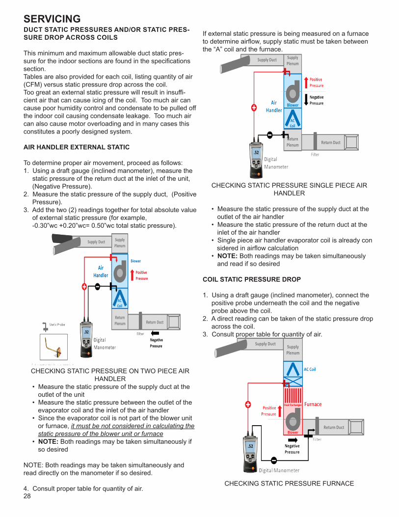
SERVICING
28
DUCT STATIC PRESSURES AND/OR STATIC PRES-SURE DROP ACROSS COILS
This minimum and maximum allowable duct static pres-sure for the indoor sections are found in the specifications section.Tables are also provided for each coil, listing quantity of air (CFM) versus static pressure drop across the coil.Too great an external static pressure will result in insuffi-cient air that can cause icing of the coil. Too much air can cause poor humidity control and condensate to be pulled off the indoor coil causing condensate leakage. Too much air can also cause motor overloading and in many cases this constitutes a poorly designed system.
AIR HANDLER EXTERNAL STATIC
To determine proper air movement, proceed as follows:1. Using a draft gauge (inclined manometer), measure the
static pressure of the return duct at the inlet of the unit, (Negative Pressure).
2. Measure the static pressure of the supply duct, (Positive Pressure).
3. Add the two (2) readings together for total absolute value of external static pressure (for example, -0.30”wc +0.20”wc= 0.50”wc total static pressure).
CHECKING STATIC PRESSURE ON TWO PIECE AIR HANDLER
• Measure the static pressure of the supply duct at the outlet of the unit • Measure the static pressure between the outlet of the evaporator coil and the inlet of the air handler • Since the evaporator coil is not part of the blower unit or furnace, it must be not considered in calculating the static pressure of the blower unit or furnace • NOTE: Both readings may be taken simultaneously if so desired
NOTE: Both readings may be taken simultaneously and read directly on the manometer if so desired.
4. Consult proper table for quantity of air.
If external static pressure is being measured on a furnace to determine airflow, supply static must be taken between the “A” coil and the furnace.
CHECKING STATIC PRESSURE SINGLE PIECE AIR HANDLER
• Measure the static pressure of the supply duct at the outlet of the air handler • Measure the static pressure of the return duct at the inlet of the air handler • Single piece air handler evaporator coil is already con sidered in airflow calculation • NOTE: Both readings may be taken simultaneously and read if so desired
COIL STATIC PRESSURE DROP
1. Using a draft gauge (inclined manometer), connect the positive probe underneath the coil and the negative probe above the coil.
2. A direct reading can be taken of the static pressure drop across the coil.
3. Consult proper table for quantity of air.
CHECKING STATIC PRESSURE FURNACE
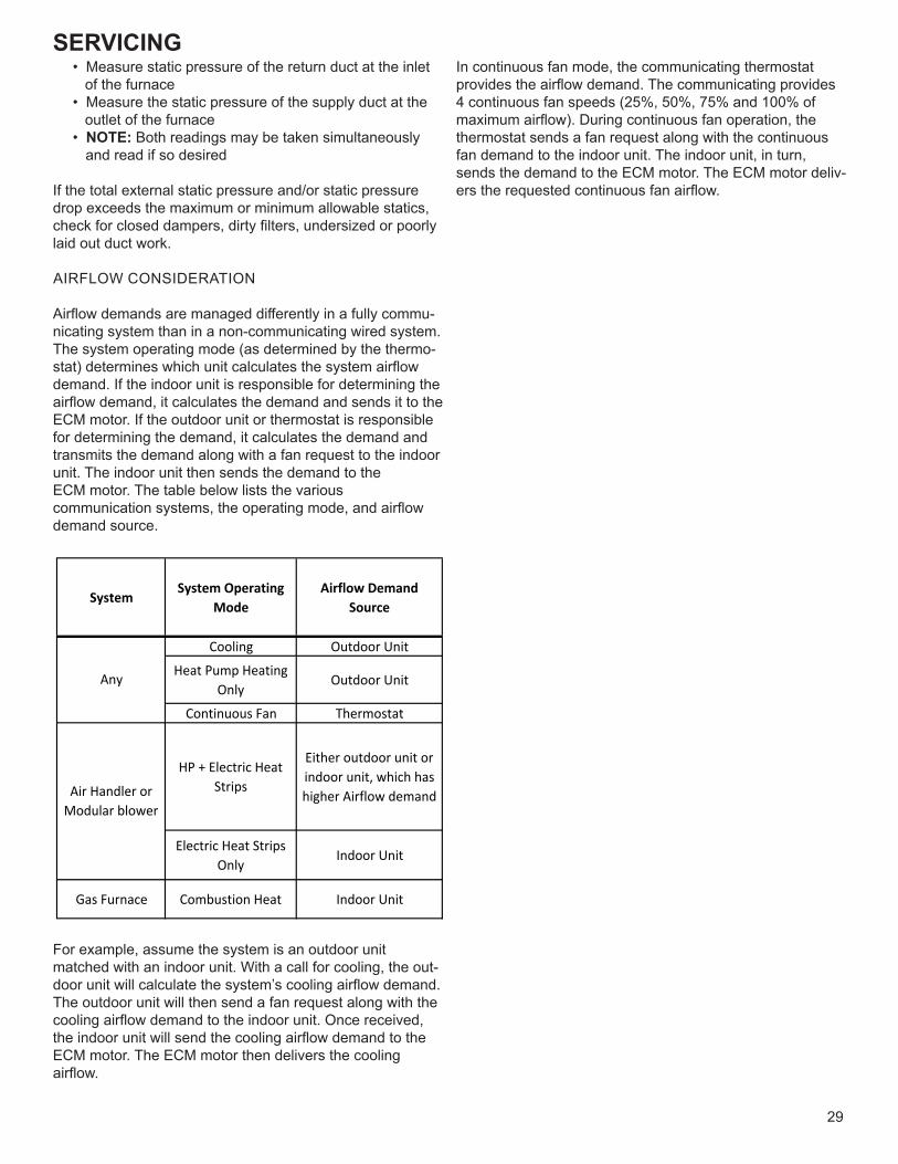
SERVICING
29
• Measure static pressure of the return duct at the inlet of the furnace • Measure the static pressure of the supply duct at the outlet of the furnace • NOTE: Both readings may be taken simultaneously and read if so desired
If the total external static pressure and/or static pressure drop exceeds the maximum or minimum allowable statics, check for closed dampers, dirty filters, undersized or poorly laid out duct work.
AIRFLOW CONSIDERATION
Airflow demands are managed differently in a fully commu-nicating system than in a non-communicating wired system. The system operating mode (as determined by the thermo-stat) determines which unit calculates the system airflow demand. If the indoor unit is responsible for determining the airflow demand, it calculates the demand and sends it to the ECM motor. If the outdoor unit or thermostat is responsible for determining the demand, it calculates the demand and transmits the demand along with a fan request to the indoor unit. The indoor unit then sends the demand to theECM motor. The table below lists the various communication systems, the operating mode, and airflow demand source.
System System OperatingMode
Airflow DemandSource
Cooling Outdoor UnitHeat Pump Heating
Only Outdoor Unit
Continuous Fan Thermostat
HP + Electric HeatStrips
Either outdoor unit orindoor unit, which hashigher Airflow demand
Electric Heat StripsOnly Indoor Unit
Gas Furnace Combustion Heat Indoor Unit
Any
Air Handler orModular blower
For example, assume the system is an outdoor unit matched with an indoor unit. With a call for cooling, the out-door unit will calculate the system’s cooling airflow demand. The outdoor unit will then send a fan request along with thecooling airflow demand to the indoor unit. Once received,the indoor unit will send the cooling airflow demand to theECM motor. The ECM motor then delivers the cooling airflow.
In continuous fan mode, the communicating thermostatprovides the airflow demand. The communicating provides4 continuous fan speeds (25%, 50%, 75% and 100% of maximum airflow). During continuous fan operation, thethermostat sends a fan request along with the continuousfan demand to the indoor unit. The indoor unit, in turn, sends the demand to the ECM motor. The ECM motor deliv-ers the requested continuous fan airflow.

SERVICING
30
COMMUNICATING BOARD
INDOOR UNIT TROUBLESHOOTING FOR TXV APPLICABLE UNIT (MBVC**00AA-1)
AUXILIARY ALARM SWITCH
The control is equipped with two Auxiliary Alarm terminals, labeled CAS, which are typically utilized in series with a condensate switch but could also be used with compatible CO2 sensors or fire alarms.
This feature can be activated or deactivated through the thermostat user menus. The auxiliary alarm switch must be normally closed and open when the alarm occurs. For ex-ample, a normally closed condensate switch will open when the base pan’s water level reaches a particular level. The control will respond by turning off the blower motor and out-door unit and displaying the proper fault codes. If the switch is later detected closed for 30 seconds, normal operation resumes and the error message is removed. The error will be maintained in the equipment’s fault history. See FIGURE 15 on the following page for the connection location.
CIRCULATOR BLOWER
This air handler is equipped with a variable speed circulator blower. This blower provides several automatically-adjusted blower speeds. The Specification Sheet applicable to your model provides an airflow table, showing the relationship between airflow (CFM) and external static pressure (E.S.P.). The electric heat dip switch default position is set to the OFF, OFF, OFF position and should be adjusted by the in-staller to match the installation requirements for the correct electric heating CFM.
Using the Electric Heat Airflow table below, set dip switch-es 9, 10, and 11 for the installed heater kit. Verify selected CFM by counting the green CFM LED blinks. The green CFM LED blinks once for each 100 CFM of airflow.If an electric heater kit has not been installed, set dip switches 9, 10, and 11 to any appropriate heater kit setting (see next page table for valid settings).During the cooling operation, the outdoor unit will determine the indoor airflow.
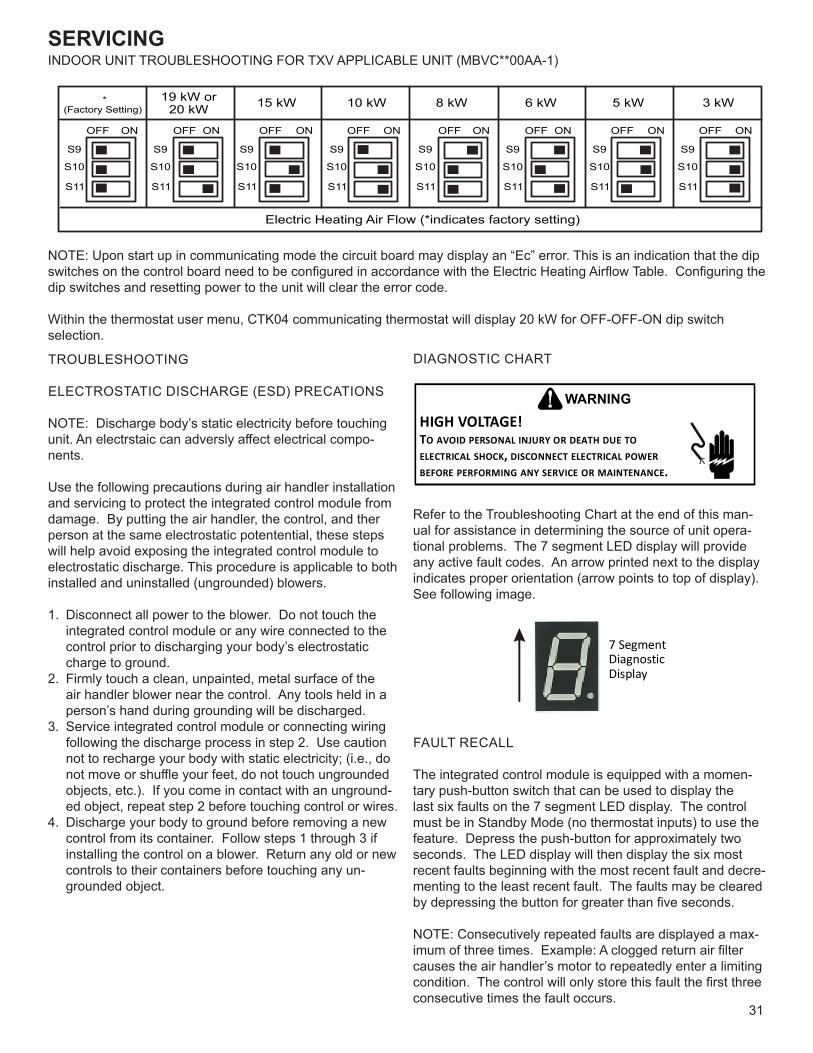
SERVICING
31
INDOOR UNIT TROUBLESHOOTING FOR TXV APPLICABLE UNIT (MBVC**00AA-1)
NOTE: Upon start up in communicating mode the circuit board may display an “Ec” error. This is an indication that the dip switches on the control board need to be configured in accordance with the Electric Heating Airflow Table. Configuring the dip switches and resetting power to the unit will clear the error code.
Within the thermostat user menu, CTK04 communicating thermostat will display 20 kW for OFF-OFF-ON dip switch selection.
TROUBLESHOOTING
ELECTROSTATIC DISCHARGE (ESD) PRECATIONS
NOTE: Discharge body’s static electricity before touching unit. An electrstaic can adversly affect electrical compo-nents.
Use the following precautions during air handler installation and servicing to protect the integrated control module from damage. By putting the air handler, the control, and ther person at the same electrostatic potentential, these steps will help avoid exposing the integrated control module to electrostatic discharge. This procedure is applicable to both installed and uninstalled (ungrounded) blowers.
1. Disconnect all power to the blower. Do not touch the integrated control module or any wire connected to the control prior to discharging your body’s electrostatic charge to ground.
2. Firmly touch a clean, unpainted, metal surface of the air handler blower near the control. Any tools held in a person’s hand during grounding will be discharged.
3. Service integrated control module or connecting wiring following the discharge process in step 2. Use caution not to recharge your body with static electricity; (i.e., do not move or shuffle your feet, do not touch ungrounded objects, etc.). If you come in contact with an unground-ed object, repeat step 2 before touching control or wires.
4. Discharge your body to ground before removing a new control from its container. Follow steps 1 through 3 if installing the control on a blower. Return any old or new controls to their containers before touching any un-grounded object.
DIAGNOSTIC CHART
HIGH VOLTAGE!TO AVOID PERSONAL INJURY OR DEATH DUE TO ELECTRICAL SHOCK, DISCONNECT ELECTRICAL POWER BEFORE PERFORMING ANY SERVICE OR MAINTENANCE.
WARNING
Refer to the Troubleshooting Chart at the end of this man-ual for assistance in determining the source of unit opera-tional problems. The 7 segment LED display will provide any active fault codes. An arrow printed next to the display indicates proper orientation (arrow points to top of display). See following image.
7 SegmentDiagnosticDisplay
FAULT RECALL
The integrated control module is equipped with a momen-tary push-button switch that can be used to display the last six faults on the 7 segment LED display. The control must be in Standby Mode (no thermostat inputs) to use the feature. Depress the push-button for approximately two seconds. The LED display will then display the six most recent faults beginning with the most recent fault and decre-menting to the least recent fault. The faults may be cleared by depressing the button for greater than five seconds.
NOTE: Consecutively repeated faults are displayed a max-imum of three times. Example: A clogged return air filter causes the air handler’s motor to repeatedly enter a limiting condition. The control will only store this fault the first three consecutive times the fault occurs.
S9
S10
OFF OFF OFF OFFON ON ON ON
*(Factory Setting)
19 kW or20 kW
Electric Heating Air Flow (*indicates factory setting)
15 kW 10 kW
OFF OFF OFF OFFON ON ON ON
8 kW 6 kW 5 kW 3 kW
S11
S9
S10
S11
S9
S10
S11
S9
S10
S11
S9
S10
S11
S9
S10
S11
S9
S10
S11
S9
S10
S11
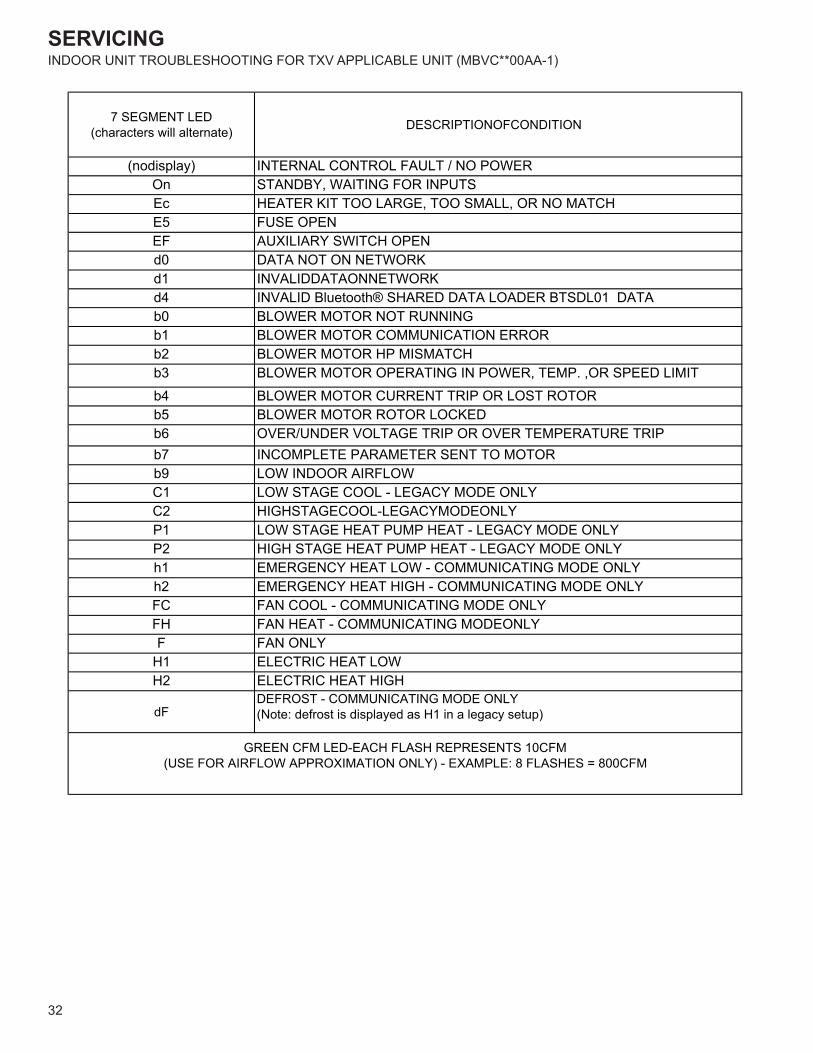
SERVICING
32
INDOOR UNIT TROUBLESHOOTING FOR TXV APPLICABLE UNIT (MBVC**00AA-1)
7 SEGMENT LED(characters will alternate) DESCRIPTIONOFCONDITION
(nodisplay) INTERNAL CONTROL FAULT / NO POWEROn STANDBY, WAITING FOR INPUTSEc HEATER KIT TOO LARGE, TOO SMALL, OR NO MATCHE5 FUSE OPENEF AUXILIARY SWITCH OPENd0 DATA NOT ON NETWORKd1 INVALIDDATAONNETWORKd4 INVALID Bluetooth® SHARED DATA LOADER BTSDL01 DATAb0 BLOWER MOTOR NOT RUNNINGb1 BLOWER MOTOR COMMUNICATION ERRORb2 BLOWER MOTOR HP MISMATCHb3 BLOWER MOTOR OPERATING IN POWER, TEMP. ,OR SPEED LIMITb4 BLOWER MOTOR CURRENT TRIP OR LOST ROTORb5 BLOWER MOTOR ROTOR LOCKEDb6 OVER/UNDER VOLTAGE TRIP OR OVER TEMPERATURE TRIPb7 INCOMPLETE PARAMETER SENT TO MOTORb9 LOW INDOOR AIRFLOWC1 LOW STAGE COOL - LEGACY MODE ONLYC2 HIGHSTAGECOOL-LEGACYMODEONLYP1 LOW STAGE HEAT PUMP HEAT - LEGACY MODE ONLYP2 HIGH STAGE HEAT PUMP HEAT - LEGACY MODE ONLYh1 EMERGENCY HEAT LOW - COMMUNICATING MODE ONLYh2 EMERGENCY HEAT HIGH - COMMUNICATING MODE ONLYFC FAN COOL - COMMUNICATING MODE ONLYFH FAN HEAT - COMMUNICATING MODEONLYF FAN ONLY
H1 ELECTRIC HEAT LOWH2 ELECTRIC HEAT HIGH
dFDEFROST - COMMUNICATING MODE ONLY(Note: defrost is displayed as H1 in a legacy setup)
GREEN CFM LED-EACH FLASH REPRESENTS 10CFM (USE FOR AIRFLOW APPROXIMATION ONLY) - EXAMPLE: 8 FLASHES = 800CFM

SERVICING
33
INDOOR UNIT TROUBLESHOOTING FOR TXV APPLICABLE UNIT (MBVC**00AA-1)
INDOOR UNIT ERROR CODESSy
mpt
oms
of A
bnor
mal
Ope
ratio
n (L
egac
y &
Com
fortN
et™
Ther
mos
tat)
7-Se
gmen
t LED
C
odes
Cha
ract
ers
Will
A
ltern
ate
Faul
t Des
crip
tion
Poss
ible
Cau
ses
Cor
rect
ive
Actio
nsN
otes
& C
autio
ns
• LE
D d
ispl
ay is
ON
con
tinuo
usly
On
• N
orm
al o
pera
tion
Non
eN
one
• N
orm
al o
pera
tion
• N
one
• N
orm
al o
pera
tion
• El
ectri
c he
ater
s fa
il to
ene
rgiz
e on
a c
all f
or
W1
or A
uxilia
ry/ E
mer
genc
y he
at•
Inte
grat
ed c
ontro
l mod
ule
LED
dis
play
pr
ovid
es t
he in
dica
ted
erro
r cod
e.•
Com
fortN
et™
ther
mos
tat “
Cal
l for
Ser
vice
” ic
on il
lum
inat
ed•
Com
fortN
et™
ther
mos
tat s
crol
ls “C
heck
Air
Han
dler
” mes
sage
EC•
Hea
ter k
it se
lect
ed v
ia
dips
witc
hes
is to
o la
rge
for
heat
er k
it s
spec
ified
in
shar
edda
ta s
et
HTR
TO
O
LAR
GE
EC
• H
eate
r kit
sele
cted
via
di
psw
itche
s is
too
larg
e fo
r hea
ter
kits
in s
hare
d da
ta s
et
• Ve
rify
elec
tric
heat
dip
switc
h se
t tin
gs•
Verif
y th
e in
stal
led
elec
tric
heat
er
is v
alid
for t
he a
ir ha
ndle
r blo
wer
. C
heck
nam
epla
te o
r Spe
cific
atio
n Sh
eet a
pplic
able
to y
our m
odel
* for
al
low
able
hea
ter k
it(s)
.•
Verif
y sh
ared
dat
a se
t is
corre
ct
for t
he s
peci
fic m
odel
. Re-
pop
ulat
e da
ta u
sing
cor
rect
Blu
etoo
th®
Sh
ared
Dat
a Lo
ader
BTS
DL0
1if
requ
ired.
• Tu
rn p
ower
OFF
prio
r to
repa
ir.•
Use
Blu
etoo
th®
Sha
red
Dat
a Lo
ader
BTS
DL0
1 fo
r the
sp
ecifi
c m
odel
.•
Inse
rt Bl
ueto
oth®
Sha
red
Dat
a Lo
ader
BTS
DL0
1 BE
FOR
Etur
ning
pow
er O
N. B
luet
ooth
®
Shar
ed D
ata
Load
er
BTSD
L01
may
be
rem
oved
af
ter d
ata
is lo
aded
.•
Turn
pow
er o
ff be
fore
re
mov
ing
Blue
toot
h® S
hare
d D
ata
Load
er B
TSD
L01.
• El
ectri
c he
at a
irflo
w is
hig
her t
han
expe
cted
on
a ca
ll fo
r W1
or
Auxi
liary
/Em
erge
ncy
heat
• In
tegr
ated
con
trol m
odul
e LE
D d
ispl
ay
prov
ides
the
indi
cate
d er
ror c
ode.
EC•
Hea
ter k
it se
lect
ed v
ia
dips
witc
hes
is to
o sm
all f
or
heat
er k
its s
peci
fied
in
shar
edda
ta s
et
HTR
TO
O
SM
ALL
EC
• H
eate
r kit
sele
cted
via
di
psw
itche
s is
too
smal
l for
hea
ter
kits
in s
hare
d da
ta s
et
• Ve
rify
elec
tric
heat
dip
switc
h se
t tin
gs•
Verif
y th
e in
stal
led
elec
tric
heat
er
is v
alid
for t
he a
ir ha
ndle
r blo
wer
. C
heck
nam
epla
te o
r Spe
cific
atio
n Sh
eet a
pplic
able
to y
our m
odel
* for
al
low
able
hea
ter k
it(s)
.•
Verif
y sh
ared
dat
a se
t is
corre
ct
for t
he s
peci
fic m
odel
. Re-
pop
ulat
e da
ta u
sing
cor
rect
Blu
etoo
th®
Sh
ared
Dat
a Lo
ader
BTS
DL0
1if
requ
ired.
• Tu
rn p
ower
OFF
prio
r to
repa
ir.•
Use
Blu
etoo
th®
Sha
red
Dat
a Lo
ader
BTS
DL0
1 fo
r the
sp
ecifi
c m
odel
.•
Inse
rt Bl
ueto
oth®
Sha
red
Dat
a Lo
ader
BTS
DL0
1 BE
FOR
Etur
ning
pow
er O
N. B
luet
ooth
®
Shar
ed D
ata
Load
er
BTSD
L01
may
be
rem
oved
af
ter d
ata
is lo
aded
.•
Turn
pow
er o
ff be
fore
re
mov
ing
Blue
toot
h® S
hare
d D
ata
Load
er B
TSD
L01.
• El
ectri
c he
at a
irflo
w is
hig
her t
han
expe
cted
on
a ca
ll fo
r W1
or A
uxilia
ry/
Emer
genc
y he
at•
Inte
grat
ed c
ontro
l mod
ule
LED
dis
play
pr
ovid
es th
e in
dica
ted
erro
r cod
e.
EC•
Hea
ter k
it se
lect
ed v
ia
dips
witc
hes
does
not
he
ater
kits
spe
cifie
d in
sh
ared
data
set
NO
HTR
M
ATC
HE
C•
Hea
ter k
it se
lect
ed v
ia
dips
witc
hes
is d
oesn
’t m
atch
he
ater
kits
in s
hare
d da
tase
t
• Ve
rify
elec
tric
heat
dip
switc
h se
t tin
gs•
Verif
y th
e in
stal
led
elec
tric
heat
er
is v
alid
for t
he a
ir ha
ndle
r blo
wer
. C
heck
nam
epla
te o
r Spe
cific
atio
n Sh
eet a
pplic
able
to y
our m
odel
* for
al
low
able
hea
ter k
it(s)
.•
Verif
y sh
ared
dat
a se
t is
corre
ct
for t
he s
peci
fic m
odel
. Re-
pop
ulat
e da
ta u
sing
cor
rect
Blu
etoo
th®
Sh
ared
Dat
a Lo
ader
BTS
DL0
1if
requ
ired.
• Tu
rn p
ower
OFF
prio
r to
repa
ir.•
Use
Blu
etoo
th®
Sha
red
Dat
a Lo
ader
BTS
DL0
1 fo
r the
sp
ecifi
c m
odel
.•
Inse
rt Bl
ueto
oth®
Sha
red
Dat
a Lo
ader
BTS
DL0
1 BE
FOR
Etur
ning
pow
er O
N. B
luet
ooth
®
Shar
ed D
ata
Load
er
BTSD
L01
may
be
rem
oved
af
ter d
ata
is lo
aded
.•
Turn
pow
er o
ff be
fore
re
mov
ing
Blue
toot
h® S
hare
d D
ata
Load
er B
TSD
L01.
• In
tegr
ated
con
trol m
odul
e LE
D d
ispl
ay E
F er
ror c
ode.
• C
omfo
rtNet
™th
erm
osta
t “C
all f
or S
ervi
ce”.
EF•
Aux
switc
h op
enAu
x Al
arm
Fa
ult
EF
• H
igh
wat
er le
vel i
n th
e ev
apor
atio
n co
il.•
Che
ck o
verfl
ow p
an a
nd s
ervi
ce•
Turn
pow
er O
FF p
rior t
o se
rvic
e.
Com
fortN
et™
Th
erm
osta
t Onl
yM
essa
ge
Cod
e
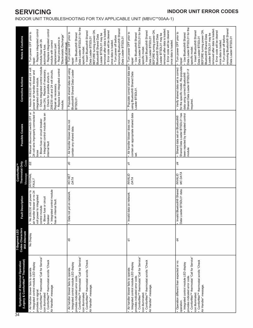
SERVICING
34
INDOOR UNIT TROUBLESHOOTING FOR TXV APPLICABLE UNIT (MBVC**00AA-1)
INDOOR UNIT ERROR CODES
Mes
sage
Cod
e•
Air h
andl
er b
low
er fa
ils to
ope
rate
• In
tegr
ated
con
trol m
odul
e LE
D d
ispl
ay
prov
ides
no
sign
al.
• C
omfo
rtNet
™ th
erm
osta
t “C
all f
or S
ervi
ce”
icon
illu
min
ated
• C
omfo
rtNet
™ th
erm
osta
t scr
olls
“Che
ck
Air H
andl
er” m
essa
ge
No
Dis
play
• N
o 20
8/23
0 vo
lt po
wer
to
air h
andl
er b
low
er o
r no
24
volt
pow
er to
inte
grat
ed
cont
rol m
odul
e•
Blow
n fu
se o
r circ
uit
brea
ker
• In
tegr
ated
con
trol m
odul
e ha
s an
inte
rnal
faul
t.
INTE
RN
AL
FAU
LTE
E•
Man
ual d
isco
nnec
t sw
itch
OFF
or
24 v
olt w
ire im
prop
erly
con
nect
ed o
r lo
ose
• Bl
own
fuse
or c
ircui
t bre
aker
• In
tegr
ated
con
trol m
odul
e ha
s an
in
tern
al fa
ult
• As
sure
208
/230
vol
t and
24
volt
pow
er to
air
hand
ler b
low
er a
nd
inte
grat
ed c
ontro
l mod
ule.
• C
heck
inte
grat
ed c
ontro
l mod
ule
fuse
(3A)
. R
epla
ce if
nec
essa
ry.
• C
heck
for p
ossi
ble
shor
ts in
20
8/23
0 vo
lt an
d 24
vol
t circ
uits
. R
epai
r as
nece
ssar
y.•
Rep
lace
bad
inte
grat
ed c
ontro
l m
odul
e.
• Tu
rn p
ower
OFF
prio
r to
repa
ir.•
Rep
lace
inte
grat
ed c
ontro
l m
odul
e fu
se w
ith 3
A au
tom
otiv
e fu
se.
• R
epla
ce in
tegr
ated
con
trol
mod
ule
with
cor
rect
re
plac
emen
t par
t•
Rea
d pr
ecau
tions
in
“Ele
ctro
stat
ic D
isch
arge
” se
ctio
n of
man
ual.
• Ai
r han
dler
blo
wer
fails
to o
pera
te.
• In
tegr
ated
con
trol m
odul
e LE
D d
ispl
ay
prov
ides
indi
cate
d er
ror c
ode.
• C
omfo
rtNet
™ th
erm
osta
t “C
all f
or S
ervi
ce”
icon
illu
min
ated
.•
Com
fortN
et™
ther
mos
tat s
crol
ls “C
heck
Ai
r Han
dler
” mes
sage
.
d0•
Dat
a no
t yet
on
netw
ork.
NO
NE
T D
ATA
d0•
Air h
andl
er b
low
er d
oes
not
cont
ain
any
shar
ed d
ata.
• Po
pula
te s
hare
d da
ta s
et u
sing
Bl
ueto
oth®
Sha
red
Dat
a Lo
ader
BT
SDL0
1.
• Tu
rn p
ower
OFF
prio
r to
repa
ir•
Use
Blu
etoo
th®
Sha
red
Dat
a Lo
ader
BTS
DL0
1 fo
r the
sp
ecifi
c m
odel
.•
Inse
rt Bl
ueto
oth®
Sha
red
Dat
a Lo
ader
BTS
DL0
1 BE
FOR
E tu
rnin
g po
wer
ON
. Bl
ueto
oth®
Sha
red
Dat
a Lo
ader
BTS
DL0
1 m
ay b
e re
mov
ed a
fter d
ata
is lo
aded
.•
Erro
r cod
e w
ill be
cle
ared
on
ce d
ata
is lo
aded
.•
Turn
pow
er o
ff be
fore
re
mov
ing
Blue
toot
h® S
hare
d D
ata
Load
er B
TSD
L01
• Ai
r han
dler
blo
wer
fails
to o
pera
te.
• In
tegr
ated
con
trol m
odul
e LE
D d
ispl
ay
prov
ides
indi
cate
d er
ror c
ode.
• C
omfo
rtNet
™ th
erm
osta
t “C
all f
or S
ervi
ce”
icon
illu
min
ated
.•
Com
fortN
et™
ther
mos
tat s
crol
ls “C
heck
Ai
r Han
dler
” mes
sage
.
d1•
Inva
lid d
ata
on n
etw
ork.
INV
ALI
D
DA
TAd1
• Ai
r han
dler
blo
wer
doe
s no
t co
ntai
n an
app
ropr
iate
sha
red
data
se
t.
• Po
pula
te c
orre
ct s
hare
d da
ta s
et
usin
g Bl
ueto
oth®
Sha
red
Dat
a Lo
ader
BTS
DL0
1.
• Tu
rn p
ower
OFF
prio
r to
repa
ir•
Use
Blu
etoo
th®
Sha
red
Dat
a Lo
ader
BTS
DL0
1 fo
r the
sp
ecifi
c m
odel
.•
Inse
rt Bl
ueto
oth®
Sha
red
Dat
a Lo
ader
BTS
DL0
1 BE
FOR
E tu
rnin
g po
wer
ON
. Bl
ueto
oth®
Sha
red
Dat
a Lo
ader
BTS
DL0
1 m
ay b
e re
mov
ed a
fter d
ata
is lo
aded
.•
Erro
r cod
e w
ill be
cle
ared
on
ce d
ata
is lo
aded
.
• O
pera
tion
diffe
rent
than
exp
ecte
d or
no
oper
atio
n.•
Inte
grat
ed c
ontro
l mod
ule
LED
dis
play
pr
ovid
es in
dica
ted
erro
r cod
e.•
Com
fortN
et™
ther
mos
tat “
Cal
l for
Ser
vice
” ic
on il
lum
inat
ed.
• C
omfo
rtNet
™ th
erm
osta
t scr
olls
“Che
ck
Air H
andl
er” m
essa
ge.
d4•
Inva
lid B
luet
ooth
® S
hare
d D
ata
Load
er B
TSD
L01
data
.IN
VA
LID
M
C D
ATA
d4•
Shar
ed d
ata
set o
n Bl
ueto
oth®
Sh
ared
Dat
a Lo
ader
BTS
DL0
1 ha
s be
en re
ject
ed b
y in
tegr
ated
con
trol
mod
ule
• Ve
rify
shar
ed d
ata
set i
s co
rrect
fo
r the
spe
cific
mod
el. R
e-po
pula
te
data
usi
ng c
orre
ct B
luet
ooth
®
Shar
ed D
ata
Load
er B
TSD
L01
if re
quire
d.
• Tu
rn p
ower
OFF
prio
r to
repa
ir•
Use
Blu
etoo
th®
Sha
red
Dat
a Lo
ader
BTS
DL0
1 fo
r the
sp
ecifi
c m
odel
.•
Inse
rt Bl
ueto
oth®
Sha
red
Dat
a Lo
ader
BTS
DL0
1 BE
FOR
E tu
rnin
g po
wer
ON
. Bl
ueto
oth®
Sha
red
Dat
a Lo
ader
BTS
DL0
1 m
ay b
e re
mov
ed a
fter d
ata
is lo
aded
.•
Erro
r cod
e w
ill be
cle
ared
on
ce d
ata
is lo
aded
.•
Turn
pow
er o
ff be
fore
re
mov
ing
Blue
toot
h® S
hare
d D
ata
Load
er B
TSD
L01
Not
es &
Cau
tions
Sym
ptom
s of
Abn
orm
al O
pera
tion
(Leg
acy
& C
omfo
rtN
et™
The
rmos
tat)
7-Se
gmen
t LED
C
odes
Cha
ract
ers
Will
Alte
rnat
eFa
ult D
escr
iptio
nC
omfo
rtN
et™
Th
erm
osta
t Onl
yPo
ssib
le C
ause
sC
orre
ctiv
e A
ctio
ns
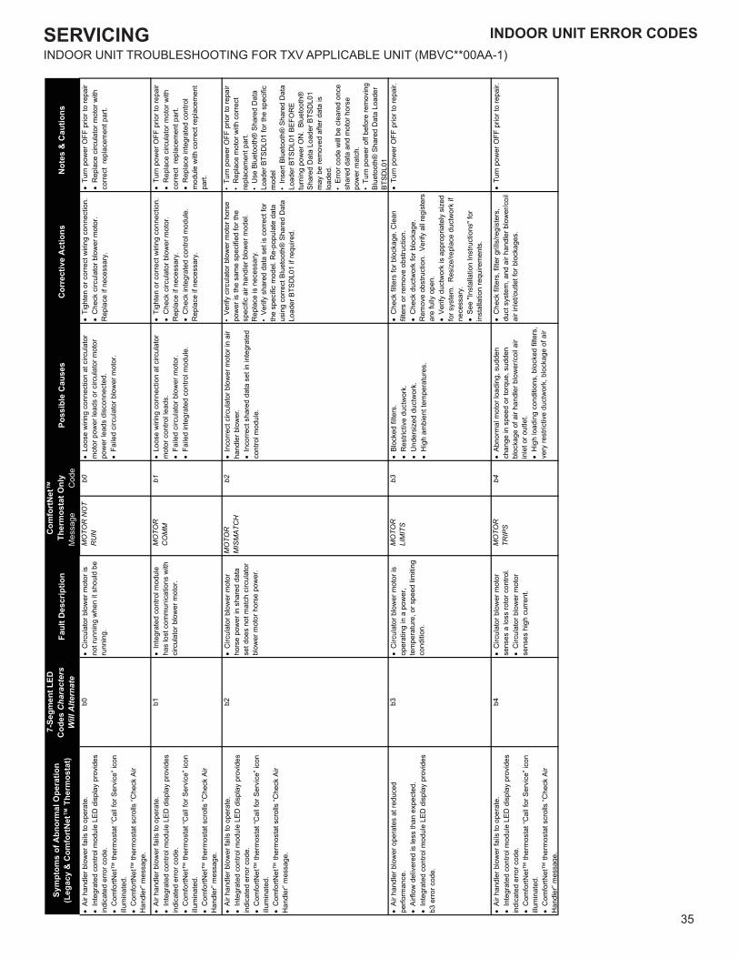
SERVICING
35
INDOOR UNIT ERROR CODES INDOOR UNIT ERROR CODESINDOOR UNIT TROUBLESHOOTING FOR TXV APPLICABLE UNIT (MBVC**00AA-1)
Mes
sage
Cod
e•
Air
hand
ler b
low
er fa
ils to
ope
rate
.•
Inte
grat
ed c
ontro
l mod
ule
LED
dis
play
pro
vide
s in
dica
ted
erro
r cod
e.•
Com
fortN
et™
ther
mos
tat “
Cal
l for
Ser
vice
” ico
n illu
min
ated
.•
Com
fortN
et™
ther
mos
tat s
crol
ls “C
heck
Air
Han
dler
” mes
sage
.
b0•
Circ
ulat
or b
low
er m
otor
is
not r
unni
ng w
hen
it sh
ould
be
runn
ing.
MO
TOR
NO
T R
UN
b0•
Loo
se w
iring
con
nect
ion
at c
ircul
ator
m
otor
pow
er le
ads
or c
ircul
ator
mot
or
pow
er le
ads
disc
onne
cted
.•
Fai
led
circ
ulat
or b
low
er m
otor
.
• T
ight
en o
r cor
rect
wiri
ng c
onne
ctio
n.•
Che
ck c
ircul
ator
blo
wer
mot
or.
Rep
lace
if n
eces
sary
.
• T
urn
pow
er O
FF p
rior t
o re
pair
• R
epla
ce c
ircul
ator
mot
or w
ith
corre
ct r
epla
cem
ent p
art.
• A
ir ha
ndle
r blo
wer
fails
to o
pera
te.
• In
tegr
ated
con
trol m
odul
e LE
D d
ispl
ay p
rovi
des
indi
cate
d er
ror c
ode.
• C
omfo
rtNet
™ th
erm
osta
t “C
all f
or S
ervi
ce” i
con
illum
inat
ed.
• C
omfo
rtNet
™ th
erm
osta
t scr
olls
“Che
ck A
ir H
andl
er” m
essa
ge.
b1•
Inte
grat
ed c
ontro
l mod
ule
has
lost
com
mun
icat
ions
with
ci
rcul
ator
blo
wer
mot
or.
MO
TOR
C
OM
Mb1
• L
oose
wiri
ng c
onne
ctio
n at
circ
ulat
or
mot
or c
ontro
l lea
ds.
• F
aile
d ci
rcul
ator
blo
wer
mot
or.
• F
aile
d in
tegr
ated
con
trol m
odul
e.
• T
ight
en o
r cor
rect
wiri
ng c
onne
ctio
n.•
Che
ck c
ircul
ator
blo
wer
mot
or.
Rep
lace
if n
eces
sary
.•
Che
ck in
tegr
ated
con
trol m
odul
e.
Rep
lace
if n
eces
sary
.
• T
urn
pow
er O
FF p
rior t
o re
pair
• R
epla
ce c
ircul
ator
mot
or w
ith
corre
ct r
epla
cem
ent p
art.
• R
epla
ce in
tegr
ated
con
trol
mod
ule
with
cor
rect
repl
acem
ent
part.
• A
ir ha
ndle
r blo
wer
fails
to o
pera
te.
• In
tegr
ated
con
trol m
odul
e LE
D d
ispl
ay p
rovi
des
indi
cate
d er
ror c
ode.
• C
omfo
rtNet
™ th
erm
osta
t “C
all f
or S
ervi
ce” i
con
illum
inat
ed.
• C
omfo
rtNet
™ th
erm
osta
t scr
olls
“Che
ck A
ir H
andl
er” m
essa
ge.
b2•
Circ
ulat
or b
low
er m
otor
ho
rse
pow
er in
sha
red
data
se
t doe
s no
t mat
ch c
ircul
ator
bl
ower
mot
or h
orse
pow
er.
MO
TOR
M
ISM
ATC
Hb2
• In
corre
ct c
ircul
ator
blo
wer
mot
or in
air
hand
ler b
low
er.
• In
corre
ct s
hare
d da
ta s
et in
inte
grat
ed
cont
rol m
odul
e.
• Ve
rify
circ
ulat
or b
low
er m
otor
hor
se
pow
er is
the
sam
e sp
ecifi
ed fo
r the
sp
ecifi
c ai
r han
dler
blo
wer
mod
el.
Rep
lace
is n
eces
sary
.•
Verif
y sh
ared
dat
a se
t is
corre
ct fo
r th
e sp
ecifi
c m
odel
. Re-
popu
late
dat
a us
ing
corre
ct B
luet
ooth
® S
hare
d D
ata
Load
er B
TSD
L01
if re
quire
d.
• Tu
rn p
ower
OFF
prio
r to
repa
ir•
Rep
lace
mot
or w
ith c
orre
ct
repl
acem
ent p
art.
• U
se B
luet
ooth
® S
hare
d D
ata
Load
er B
TSD
L01
for t
he s
peci
fic
mod
el•
Inse
rt Bl
ueto
oth®
Sha
red
Dat
a Lo
ader
BTS
DL0
1 BE
FOR
E tu
rnin
g po
wer
ON
. Bl
ueto
oth®
Sh
ared
Dat
a Lo
ader
BTS
DL0
1 m
ay b
e re
mov
ed a
fter d
ata
is
load
ed.
• Er
ror c
ode
will
be c
lear
ed o
nce
shar
ed d
ata
and
mot
or h
orse
po
wer
mat
ch.
• Tu
rn p
ower
off
befo
re re
mov
ing
Blue
toot
h® S
hare
d D
ata
Load
er
BTSD
L01
• A
ir ha
ndle
r blo
wer
ope
rate
s at
redu
ced
perfo
rman
ce.
• A
irflo
w d
eliv
ered
is le
ss th
an e
xpec
ted.
• In
tegr
ated
con
trol m
odul
e LE
D d
ispl
ay p
rovi
des
b3 e
rror c
ode.
b3•
Circ
ulat
or b
low
er m
otor
is
oper
atin
g in
a p
ower
, te
mpe
ratu
re, o
r spe
ed li
miti
ng
cond
ition
.
MO
TOR
LI
MIT
Sb3
• B
lock
ed fi
lters
.•
Res
trict
ive
duct
wor
k.•
Und
ersi
zed
duct
wor
k.•
Hig
h am
bien
t tem
pera
ture
s.
• C
heck
filte
rs fo
r blo
ckag
e. C
lean
fil
ters
or r
emov
e ob
stru
ctio
n.•
Che
ck d
uctw
ork
for b
lock
age.
R
emov
e ob
stru
ctio
n. V
erify
all
regi
ster
s ar
e fu
lly o
pen.
• V
erify
duc
twor
k is
app
ropr
iate
ly s
ized
fo
r sys
tem
. R
esiz
e/re
plac
e du
ctw
ork
if ne
cess
ary.
• S
ee "I
nsta
llatio
n In
stru
ctio
ns" f
or
inst
alla
tion
requ
irem
ents
.
• T
urn
pow
er O
FF p
rior t
o re
pair.
• A
ir ha
ndle
r blo
wer
fails
to o
pera
te.
• In
tegr
ated
con
trol m
odul
e LE
D d
ispl
ay p
rovi
des
indi
cate
d er
ror c
ode.
• C
omfo
rtNet
™ th
erm
osta
t “C
all f
or S
ervi
ce” i
con
illum
inat
ed.
• C
omfo
rtNet
™ th
erm
osta
t scr
olls
“Che
ck A
ir H
andl
er” m
essa
ge.
b4•
Circ
ulat
or b
low
er m
otor
se
nses
a lo
ss ro
tor c
ontro
l.•
Circ
ulat
or b
low
er m
otor
se
nses
hig
h cu
rrent
.
MO
TOR
TR
IPS
b4•
Abn
orm
al m
otor
load
ing,
sud
den
chan
ge in
spe
ed o
r tor
que,
sud
den
bloc
kage
of a
ir ha
ndle
r blo
wer
/coi
l air
inle
t or o
utle
t.•
Hig
h lo
adin
g co
nditi
ons,
blo
cked
filte
rs,
very
rest
rictiv
e du
ctw
ork,
blo
ckag
e of
air
• C
heck
filte
rs, f
ilter
gril
ls/re
gist
ers,
du
ct s
yste
m, a
nd a
ir ha
ndle
r blo
wer
/coi
l ai
r inl
et/o
utle
t for
blo
ckag
es.
• T
urn
pow
er O
FF p
rior t
o re
pair.
Not
es &
Cau
tions
Sym
ptom
s of
Abn
orm
al O
pera
tion
(Leg
acy
& C
omfo
rtN
et™
The
rmos
tat)
7-Se
gmen
t LED
C
odes
Cha
ract
ers
Will
Alte
rnat
eFa
ult D
escr
iptio
nC
omfo
rtN
et™
Th
erm
osta
t Onl
yPo
ssib
le C
ause
sC
orre
ctiv
e A
ctio
ns
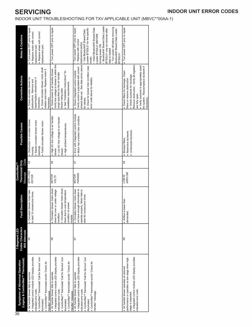
SERVICING
36
INDOOR UNIT ERROR CODESINDOOR UNIT TROUBLESHOOTING FOR TXV APPLICABLE UNIT (MBVC**00AA-1)
Mes
sage
Cod
e•
Air
hand
ler b
low
er fa
ils to
ope
rate
.•
Inte
grat
ed c
ontro
l mod
ule
LED
dis
play
pro
vide
s in
dica
ted
erro
r cod
e.•
Com
fortN
et™
ther
mos
tat “
Cal
l for
Ser
vice
” ico
n illu
min
ated
.•
Com
fortN
et™
ther
mos
tat s
crol
ls “C
heck
Air
Han
dler
” mes
sage
.
b5•
Circ
ulat
or b
low
er m
otor
fails
to
sta
rt 10
con
secu
tive
times
.M
TR L
CK
D
RO
TOR
b5•
Obs
truct
ion
in c
ircul
ator
blo
wer
ho
usin
g.•
Sei
zed
circ
ulat
or b
low
er m
otor
be
arin
gs.
• F
aile
d ci
rcul
ator
blo
wer
mot
or.
• C
heck
circ
ulat
or b
low
er fo
r ob
stru
ctio
ns.
Rem
ove
and
repa
ir/re
plac
e w
heel
/mot
or if
ne
cess
ary.
• C
heck
circ
ulat
or b
low
er m
otor
sha
ft ro
tatio
n an
d m
otor
. Rep
lace
mot
or if
ne
cess
ary.
• T
urn
pow
er O
FF p
rior t
o re
pair
• R
epla
ce m
otor
with
cor
rect
re
plac
emen
t par
t.•
Rep
lace
whe
el w
ith c
orre
ct
repl
acem
ent p
art.
• A
ir ha
ndle
r blo
wer
fails
to o
pera
te.
• In
tegr
ated
con
trol m
odul
e LE
D d
ispl
ay p
rovi
des
indi
cate
d er
ror c
ode.
• C
omfo
rtNet
™ th
erm
osta
t “C
all f
or S
ervi
ce” i
con
illum
inat
ed.
• C
omfo
rtNet
™ th
erm
osta
t scr
olls
“Che
ck A
ir H
andl
er” m
essa
ge.
b6•
Circ
ulat
or b
low
er m
otor
shu
ts
dow
n fo
r ove
r or u
nder
vol
tage
co
nditi
on.
• C
ircul
ator
blo
wer
mot
or s
huts
do
wn
due
to o
ver t
empe
ratu
re
cond
ition
on
pow
erm
odul
e.
MO
TOR
V
OLT
Sb6
• H
igh
AC li
ne v
olta
ge to
air
hand
ler
blow
er.
• L
ow A
C li
ne v
olta
ge to
air
hand
er
blow
er.
• H
igh
ambi
ent t
empe
ratu
res.
• C
heck
pow
er to
air
hand
ler b
low
er.
Verif
y lin
e vo
ltage
to b
low
er is
with
in th
e ra
nge
spec
ified
on
the
air h
andl
er
blow
er ra
ting
plat
e.•
See
"Ins
talla
tion
Inst
ruct
ions
" for
in
stal
latio
n re
quire
men
ts.
• T
urn
pow
er O
FF p
rior t
o re
pair.
• A
ir ha
ndle
r blo
wer
fails
to o
pera
te.
• In
tegr
ated
con
trol m
odul
e LE
D d
ispl
ay p
rovi
des
indi
cate
d er
ror c
ode.
• C
omfo
rtNet
™ th
erm
osta
t “C
all f
or S
ervi
ce” i
con
illum
inat
ed.
• C
omfo
rtNet
™ th
erm
osta
t scr
olls
“Che
ck A
ir H
andl
er” m
essa
ge.
b7•
Circ
ulat
or b
low
er m
otor
doe
s no
t hav
e en
ough
info
rmat
ion
to
oper
ate
prop
erly
. Mot
or fa
ils to
st
art 4
0 co
nsec
utiv
e tim
es.
MO
TOR
P
AR
AM
Sb7
• E
rror w
ith in
tegr
ated
con
trol m
odul
e.•
Mot
or h
as a
lock
ed ro
tor c
ondi
tion.
• C
heck
inte
grat
ed c
ontro
l mod
ule.
Ve
rify
cont
rol i
s po
pula
ted
with
cor
rect
sh
ared
dat
a se
t. S
ee d
ata
erro
rs a
bove
fo
r det
ails
.•
Che
ck fo
r loc
ked
roto
r con
ditio
n (s
ee
erro
r cod
e ab
ove
for d
etai
ls).
• Tu
rn p
ower
OFF
prio
r to
repa
ir.•
Rep
lace
with
cor
rect
re
plac
emen
t par
t(s).
• U
se B
luet
ooth
® S
hare
d D
ata
Load
er B
TSD
L01
for t
he s
peci
fic
mod
el.
• In
sert
Blue
toot
h® S
hare
d D
ata
Load
er B
TSD
L01
BEFO
RE
turn
ing
pow
er O
N.
• Bl
ueto
oth®
Sha
red
Dat
a Lo
ader
BT
SDL0
1 m
ay b
e re
mov
ed a
fter
data
is lo
aded
• Tu
rn p
ower
off
befo
re re
mov
ing
Blue
toot
h® S
hare
d D
ata
Load
er
BTSD
L01.
• A
ir ha
ndle
r blo
wer
ope
rate
s at
redu
ced
perfo
rman
ce o
r ope
rate
s on
low
sta
ge w
hen
high
st
age
is e
xpec
ted.
• In
tegr
ated
con
trol m
odul
e LE
D d
ispl
ay p
rovi
des
indi
cate
d er
ror c
ode.
b9•
Airf
low
is lo
wer
than
de
man
ded.
LOW
ID
AIR
FLO
Wb9
• B
lock
ed fi
lters
.•
Res
trict
ive
duct
wor
k.•
Und
ersi
zed
duct
wor
k.
• C
heck
filte
rs fo
r blo
ckag
e. C
lean
fil
ters
or r
emov
e ob
stru
ctio
n.•
Che
ck d
uctw
ork
for b
lock
age.
R
emov
e ob
stru
ctio
n. V
erify
all
regi
ster
s ar
e fu
lly o
pen.
• V
erify
duc
twor
k is
app
ropr
iate
ly s
ized
fo
r sys
tem
. R
esiz
e/re
plac
e du
ctw
ork
if ne
cess
ary.
• T
urn
pow
er O
FF p
rior t
o re
pair.
Not
es &
Cau
tions
Sym
ptom
s of
Abn
orm
al O
pera
tion
(Leg
acy
& C
omfo
rtN
et™
The
rmos
tat)
7-Se
gmen
t LED
C
odes
Cha
ract
ers
Will
Alte
rnat
eFa
ult D
escr
iptio
nC
omfo
rtN
et™
Th
erm
osta
t Onl
yPo
ssib
le C
ause
sC
orre
ctiv
e A
ctio
ns
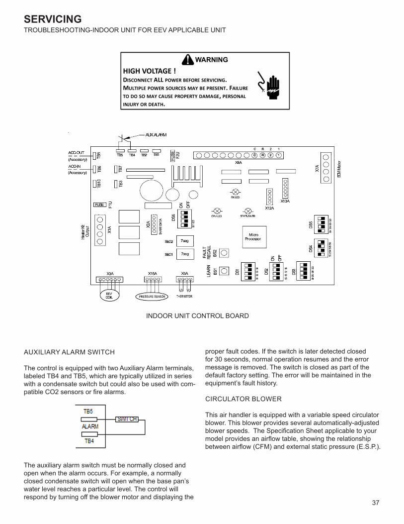
SERVICING
37
INDOOR UNIT ERROR CODESTROUBLESHOOTING-INDOOR UNIT FOR EEV APPLICABLE UNIT
HIGH VOLTAGE !DISCONNECT ALL POWER BEFORE SERVICING. MULTIPLE POWER SOURCES MAY BE PRESENT. FAILURE TO DO SO MAY CAUSE PROPERTY DAMAGE, PERSONAL INJURY OR DEATH.
WARNING
INDOOR UNIT CONTROL BOARD
AUXILIARY ALARM SWITCH
The control is equipped with two Auxiliary Alarm terminals, labeled TB4 and TB5, which are typically utilized in series with a condensate switch but could also be used with com-patible CO2 sensors or fire alarms.
The auxiliary alarm switch must be normally closed and open when the alarm occurs. For example, a normally closed condensate switch will open when the base pan’s water level reaches a particular level. The control will respond by turning off the blower motor and displaying the
proper fault codes. If the switch is later detected closed for 30 seconds, normal operation resumes and the error message is removed. The switch is closed as part of the default factory setting. The error will be maintained in the equipment’s fault history.
CIRCULATOR BLOWER
This air handler is equipped with a variable speed circulator blower. This blower provides several automatically-adjusted blower speeds. The Specification Sheet applicable to your model provides an airflow table, showing the relationship between airflow (CFM) and external static pressure (E.S.P.).
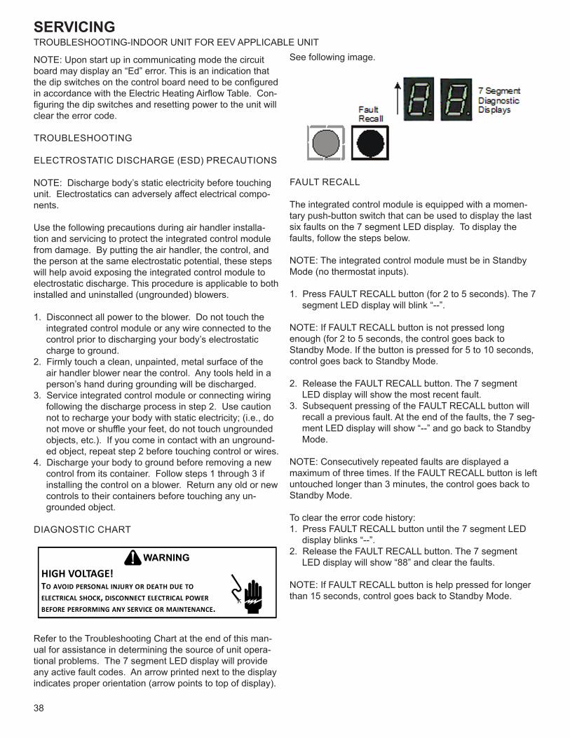
SERVICING
38
TROUBLESHOOTING-INDOOR UNIT FOR EEV APPLICABLE UNIT
NOTE: Upon start up in communicating mode the circuit board may display an “Ed” error. This is an indication that the dip switches on the control board need to be configured in accordance with the Electric Heating Airflow Table. Con-figuring the dip switches and resetting power to the unit will clear the error code.
TROUBLESHOOTING
ELECTROSTATIC DISCHARGE (ESD) PRECAUTIONS
NOTE: Discharge body’s static electricity before touching unit. Electrostatics can adversely affect electrical compo-nents.
Use the following precautions during air handler installa-tion and servicing to protect the integrated control module from damage. By putting the air handler, the control, and the person at the same electrostatic potential, these steps will help avoid exposing the integrated control module to electrostatic discharge. This procedure is applicable to both installed and uninstalled (ungrounded) blowers.
1. Disconnect all power to the blower. Do not touch the integrated control module or any wire connected to the control prior to discharging your body’s electrostatic charge to ground.
2. Firmly touch a clean, unpainted, metal surface of the air handler blower near the control. Any tools held in a person’s hand during grounding will be discharged.
3. Service integrated control module or connecting wiring following the discharge process in step 2. Use caution not to recharge your body with static electricity; (i.e., do not move or shuffle your feet, do not touch ungrounded objects, etc.). If you come in contact with an unground-ed object, repeat step 2 before touching control or wires.
4. Discharge your body to ground before removing a new control from its container. Follow steps 1 through 3 if installing the control on a blower. Return any old or new controls to their containers before touching any un-grounded object.
DIAGNOSTIC CHART
HIGH VOLTAGE!TO AVOID PERSONAL INJURY OR DEATH DUE TO ELECTRICAL SHOCK, DISCONNECT ELECTRICAL POWER BEFORE PERFORMING ANY SERVICE OR MAINTENANCE.
WARNING
Refer to the Troubleshooting Chart at the end of this man-ual for assistance in determining the source of unit opera-tional problems. The 7 segment LED display will provide any active fault codes. An arrow printed next to the display indicates proper orientation (arrow points to top of display).
See following image.
FAULT RECALL
The integrated control module is equipped with a momen-tary push-button switch that can be used to display the last six faults on the 7 segment LED display. To display the faults, follow the steps below.
NOTE: The integrated control module must be in Standby Mode (no thermostat inputs).
1. Press FAULT RECALL button (for 2 to 5 seconds). The 7 segment LED display will blink “--”.
NOTE: If FAULT RECALL button is not pressed long enough (for 2 to 5 seconds, the control goes back to Standby Mode. If the button is pressed for 5 to 10 seconds, control goes back to Standby Mode.
2. Release the FAULT RECALL button. The 7 segment LED display will show the most recent fault.
3. Subsequent pressing of the FAULT RECALL button will recall a previous fault. At the end of the faults, the 7 seg-ment LED display will show “--” and go back to Standby Mode.
NOTE: Consecutively repeated faults are displayed a maximum of three times. If the FAULT RECALL button is left untouched longer than 3 minutes, the control goes back to Standby Mode.
To clear the error code history:1. Press FAULT RECALL button until the 7 segment LED
display blinks “--”.2. Release the FAULT RECALL button. The 7 segment
LED display will show “88” and clear the faults.
NOTE: If FAULT RECALL button is help pressed for longer than 15 seconds, control goes back to Standby Mode.
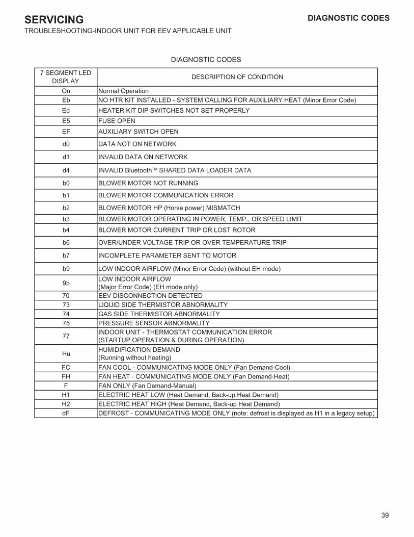
SERVICING
39
TROUBLESHOOTING-INDOOR UNIT FOR EEV APPLICABLE UNIT
DIAGNOSTIC CODES
On Normal OperationEb NO HTR KIT INSTALLED - SYSTEM CALLING FOR AUXILIARY HEAT (Minor Error Code)Ed HEATER KIT DIP SWITCHES NOT SET PROPERLYE5 FUSE OPENEF AUXILIARY SWITCH OPEN
d0 DATA NOT ON NETWORK
d1 INVALID DATA ON NETWORK
d4 INVALID BluetoothTM SHARED DATA LOADER DATA
b0 BLOWER MOTOR NOT RUNNING
b1 BLOWER MOTOR COMMUNICATION ERROR
b2 BLOWER MOTOR HP (Horse power) MISMATCH
b3 BLOWER MOTOR OPERATING IN POWER, TEMP., OR SPEED LIMIT
b4 BLOWER MOTOR CURRENT TRIP OR LOST ROTOR
b6 OVER/UNDER VOLTAGE TRIP OR OVER TEMPERATURE TRIP
b7 INCOMPLETE PARAMETER SENT TO MOTOR
b9 LOW INDOOR AIRFLOW (Minor Error Code) (without EH mode)
9b LOW INDOOR AIRFLOW(Major Error Code) (EH mode only)
70 EEV DISCONNECTION DETECTED73 LIQUID SIDE THERMISTOR ABNORMALITY74 GAS SIDE THERMISTOR ABNORMALITY75 PRESSURE SENSOR ABNORMALITY
77 INDOOR UNIT - THERMOSTAT COMMUNICATION ERROR(STARTUP OPERATION & DURING OPERATION)
Hu HUMIDIFICATION DEMAND(Running without heating)
FC FAN COOL - COMMUNICATING MODE ONLY (Fan Demand-Cool)FH FAN HEAT - COMMUNICATING MODE ONLY (Fan Demand-Heat)F FAN ONLY (Fan Demand-Manual)
H1 ELECTRIC HEAT LOW (Heat Demand, Back-up Heat Demand)H2 ELECTRIC HEAT HIGH (Heat Demand, Back-up Heat Demand)dF DEFROST - COMMUNICATING MODE ONLY (note: defrost is displayed as H1 in a legacy setup)
7 SEGMENT LED DISPLAY DESCRIPTION OF CONDITION
DIAGNOSTIC CODES
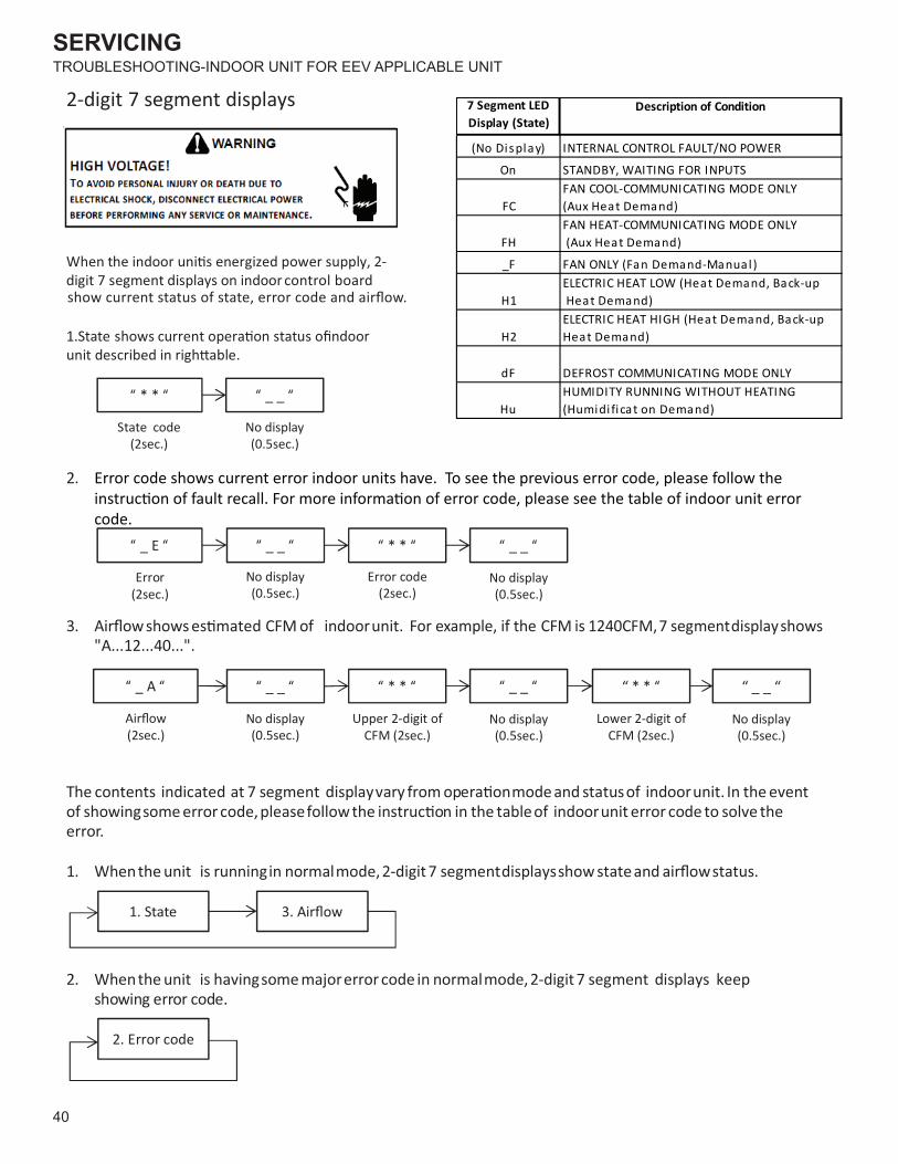
SERVICING
40
TROUBLESHOOTING-INDOOR UNIT FOR EEV APPLICABLE UNIT
error.
“ * * “ “ _ _ “
No display(0.5sec.)
“ _ E “ “ _ _ “ “ * * “ “ _ _ “
Error(2sec.)
“ _ A “ “ _ _ “ “ * * “ “ _ _ “ “ * * “ “ _ _ “
digit 7 segment displays on indoor control board
State code(2sec.)
No display(0.5sec.)
Error code(2sec.)
No display(0.5sec.)
(2sec.)No display(0.5sec.)
Upper 2-digit ofCFM (2sec.)
Lower 2-digit ofCFM (2sec.)
No display(0.5sec.)
No display(0.5sec.)
2-digit 7 segment displays
2.
"A...12...40...".
1. State
2. Error code
2. Whenthe unit is havingsome majorerror code in normalmode,2-digit 7 segment displays keepshowing error code.
indoorunit. In the eventindoorunit error code to solve the
For example, if the CFM is 1240CFM,7 segmentdisplayshows
show current status of state, error code and airflow.
7 Segment LED Display (State)
(No Display) INTERNAL CONTROL FAULT/NO POWER
On
FC
FH
_F
H1
H2
dF
Hu
ELECTRIC HEAT LOW (Heat Demand, Back-up Heat Demand)ELECTRIC HEAT HIGH (Heat Demand, Back-up Heat Demand)
HUMIDITY RUNNING WITHOUT HEATING (Humidi ficat on Demand)
Description of Condition
STANDBY, WAITING FOR INPUTSFAN COOL-COMMUNICATING MODE ONLY (Aux Heat Demand)FAN HEAT-COMMUNICATING MODE ONLY (Aux Heat Demand)
FAN ONLY (Fan Demand-Manual )
DEFROST COMMUNICATING MODE ONLY
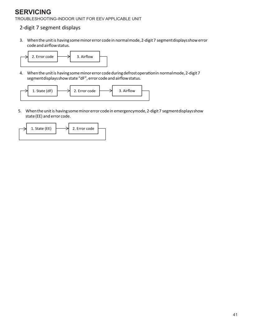
SERVICING
41
TROUBLESHOOTING-INDOOR UNIT FOR EEV APPLICABLE UNIT
1. State (dF) 2. Error code 3. Airflow
1. State (EE) 2. Error code
2-digit 7 segment displays
4. Whenthe unit is havingsome minorerror code duringdefrostopera�onin normalmode,2-digit 7segmentdisplaysshow state “dF”, error code and airflowstatus.
2. Error code 3. Airflow
3. Whenthe unit is havingsome minorerror code in normalmode,2-digit 7 segmentdisplaysshow errorcode and airflowstatus.
5. Whenthe unit is havingsome minorerror code in emergencymode,2-digit 7 segmentdisplaysshowstate (EE) and error code.
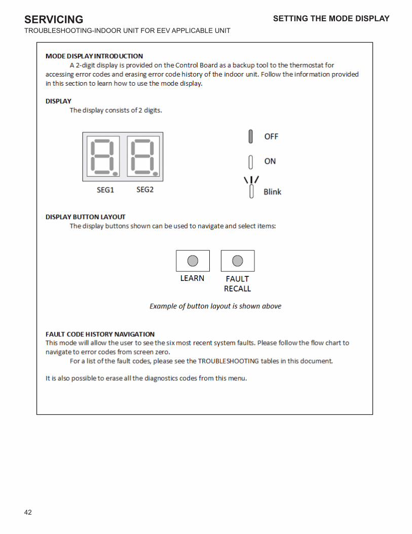
SERVICING
42
TROUBLESHOOTING-INDOOR UNIT FOR EEV APPLICABLE UNIT
SETTING THE MODE DISPLAY
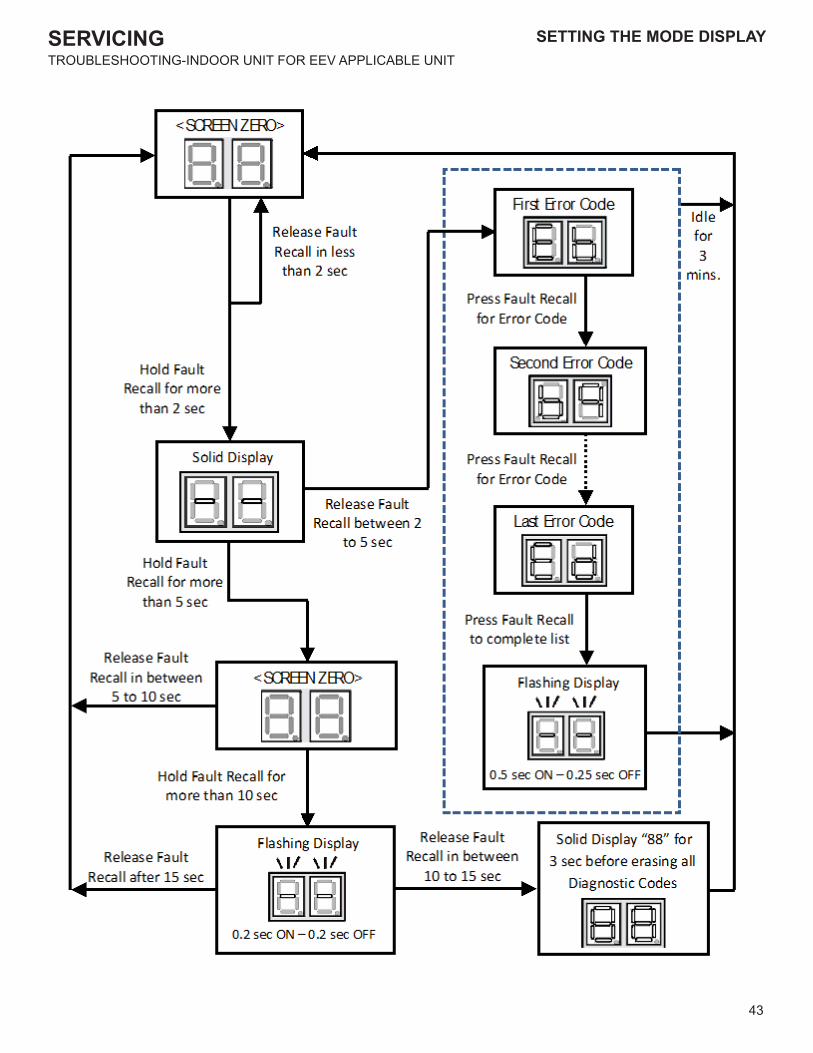
SERVICING
43
SETTING THE MODE DISPLAYTROUBLESHOOTING-INDOOR UNIT FOR EEV APPLICABLE UNIT
SETTING THE MODE DISPLAY
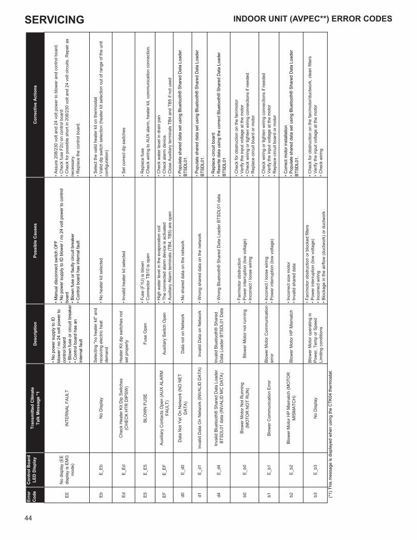
SERVICING
44
INDOOR UNIT (AVPEC**) ERROR CODESEr
ror
Cod
eC
ontr
ol B
oard
LED
Dis
play
Tran
smitt
ed C
limat
eTa
lk M
essa
ge *1
Des
crip
tion
Poss
ible
Cau
ses
Cor
rect
ive
Act
ions
EEN
o di
spla
y (E
E di
spla
y is
EM
G
mod
e)IN
TER
NAL
FAU
LT
• No
pow
er s
uppl
y to
ID
blow
er /
no 2
4 vo
lt po
wer
to
cont
rol b
oard
• Blo
wn
fuse
or c
ircui
t bre
aker
• Con
trol b
oard
has
an
inte
rnal
faul
t
• Man
ual d
isco
nnec
t sw
itch
OFF
• No
pow
er s
uppl
y to
ID b
low
er /
no 2
4 vo
lt po
wer
to c
ontro
l bo
ard
• Blo
wn
fuse
or f
aulty
circ
uit b
reak
er• C
ontro
l boa
rd h
as in
tern
al fa
ult
• Ass
ure
208/
230
volt
and
24 v
olt p
ower
to b
low
er a
nd c
ontro
l boa
rd.
• Che
ck fu
se F
2U o
n co
ntro
l boa
rd• C
heck
for p
ossi
ble
shor
t in
208/
230
volt
and
24 v
olt c
ircui
ts. R
epai
r as
nece
ssar
y.• R
epla
ce th
e co
ntro
l boa
rd.
EbE_
EbN
o D
ispl
aySe
lect
ing
"no
heat
er k
it" a
nd
rece
ivin
g el
ectri
c he
at
dem
and
• No
heat
er k
it se
lect
ed• S
elec
t the
val
id h
eate
r kit
on th
erm
osta
t• V
alid
dip
sw
itch
sele
ctio
n (h
eate
r kit
sele
ctio
n ou
t of r
ange
of t
he u
nit
conf
igur
atio
n)
EdE_
EdC
heck
Hea
ter K
it D
ip S
witc
hes
(CH
ECK
HTR
DIP
SW)
Hea
ter K
it di
p sw
itche
s no
t se
t pro
perly
• Inv
alid
hea
ter k
it se
lect
ed• S
et c
orre
ct d
ip s
witc
hes
E5E_
E5BL
OW
N F
USE
Fuse
Ope
n• F
use
(F1U
) is
blow
n• C
onne
ctor
TB1
0 is
ope
n• R
epla
ce fu
se• C
heck
wiri
ng to
AU
X al
arm
, hea
ter k
it, c
omm
unic
atio
n co
nnec
tion.
EFE_
EFAu
xilia
ry C
onta
cts
Ope
n (A
UX
ALAR
MFA
ULT
)Au
xilia
ry S
witc
h O
pen
• Hig
h w
ater
leve
l in
the
evap
orat
ion
coil
• The
con
nect
ed a
larm
dev
ice
is a
ctiv
ated
• Aux
iliary
Ala
rm te
rmin
als
(TB4
, TB5
) are
ope
n
• Che
ck w
ater
leve
l in
drai
n pa
n• C
heck
ala
rm d
evic
e.• C
lose
Aux
iliary
term
inal
s TB
4 an
d TB
5 if
not u
sed
d0E_
d0D
ata
Not
Yet
On
Net
wor
k (N
O N
ETD
ATA)
Dat
a no
t on
Net
wor
k• N
o sh
ared
dat
a on
the
netw
ork
• Pop
ulat
e sh
ared
dat
a se
t usi
ng B
luet
ooth
® S
hare
d D
ata
Load
er
BTSD
L01.
d1E_
d1In
valid
Dat
a O
n N
etw
ork
(INVA
LID
DAT
A)In
valid
Dat
a on
Net
wor
k• W
rong
sha
red
data
on
the
netw
ork
• Pop
ulat
e sh
ared
dat
a se
t usi
ng B
luet
ooth
® S
hare
d D
ata
Load
er
BTSD
L01.
d4E_
d4In
valid
Blu
etoo
th®
Sha
red
Dat
a Lo
ader
BT
SDL0
1 da
ta (I
NVA
LID
MC
DAT
A)In
valid
Blu
etoo
th®
Sha
red
Dat
a Lo
ader
BTS
DL0
1 D
ata
• Wro
ng B
luet
ooth
® S
hare
d D
ata
Load
er B
TSD
L01
data
• Rep
lace
circ
uit b
oard
• Rew
rite
data
usi
ng th
e co
rrect
Blu
etoo
th®
Sha
red
Dat
a Lo
ader
BT
SDL0
1
b0E_
b0Bl
ower
Mot
or N
ot R
unni
ng(M
OTO
R N
OT
RU
N)
Blow
er M
otor
not
runn
ing
• Fan
/mot
or o
bstru
ctio
n• P
ower
inte
rrupt
ion
(low
vol
tage
)• I
ncor
rect
/ lo
ose
wiri
ng
• Che
ck fo
r obs
truct
ion
on th
e fa
n/m
otor
• Ver
ify th
e in
put v
olta
ge a
t the
mot
or• C
heck
wiri
ng o
r tig
hten
wiri
ng c
onne
ctio
ns if
nee
ded
• Rep
lace
circ
uit b
oard
or m
otor
b1E_
b1Bl
ower
Com
mun
icat
ion
Erro
rBl
ower
Mot
or C
omm
unic
atio
n er
ror
• Inc
orre
ct /
loos
e w
iring
• Pow
er in
terru
ptio
n (lo
w v
olta
ge)
• Che
ck w
iring
or t
ight
en w
iring
con
nect
ions
if n
eede
d• V
erify
the
inpu
t vol
tage
at t
he m
otor
• Rep
lace
circ
uit b
oard
or m
otor
b2E_
b2Bl
ower
Mot
or H
P M
ism
atch
(MO
TOR
M
ISM
ATC
H)
Blow
er M
otor
HP
Mis
mat
ch• I
ncor
rect
siz
e m
otor
• Inv
alid
sha
red
data
• Cor
rect
mot
or in
stal
latio
n• P
opul
ate
shar
ed d
ata
set u
sing
Blu
etoo
th®
Sha
red
Dat
a Lo
ader
BT
SDL0
1.
b3E_
b3N
o D
ispl
ayBl
ower
Mot
or o
pera
ting
in
Pow
er, T
emp
or S
peed
Li
miti
ng c
ondi
tions
• Fan
/mot
or o
bstru
ctio
n or
blo
cked
filte
rs• P
ower
inte
rrupt
ion
(low
vol
tage
)• I
ncor
rect
wiri
ng• B
lock
age
in th
e ai
rflow
(duc
twor
k) o
r duc
twor
k
• Che
ck fo
r obs
truct
ion
on th
e fa
n/m
otor
/duc
twor
k, c
lean
filte
rs• V
erify
the
inpu
t vol
tage
at t
he m
otor
• Che
ck w
iring
(*1)
Thi
s m
essa
ge is
dis
play
ed w
hen
usin
g th
e C
TK04
ther
mos
tat.

SERVICING
45
INDOOR UNIT (AVPEC**) ERROR CODES INDOOR UNIT (AVPEC**) ERROR CODESEr
ror
Cod
eC
ontr
ol B
oard
LED
Dis
play
Tran
smitt
ed C
limat
eTa
lk M
essa
ge *1
Des
crip
tion
Poss
ible
Cau
ses
Cor
rect
ive
Act
ions
b4E_
b4Bl
ower
Trip
or L
ost R
otor
(MO
TOR
TR
IPS)
Blow
er M
otor
- C
urre
nt T
rip
(or)
Lost
Rot
or
• Fan
/mot
or o
bstru
ctio
n or
abn
orm
al m
otor
load
ing
• Pow
er in
terru
ptio
n (lo
w v
olta
ge)
• Hig
h lo
adin
g co
nditi
ons,
blo
cked
filte
rs• B
lock
age
in th
e ai
rflow
(duc
twor
k)
or d
uctw
ork
• Che
ck fo
r obs
truct
ion
on th
e fa
n/m
otor
/duc
twor
k• V
erify
the
inpu
t vol
tage
at t
he m
otor
• Che
ck fi
lters
, gril
ls, d
uct s
yste
m, c
oil a
ir in
let/o
utle
t for
blo
ckag
es.
b6E_
b6Vo
ltage
or T
empe
ratu
re T
rip (M
OTO
R
VOLT
S)
• Blo
wer
mot
or s
tops
for
over
/und
er v
olta
ge• B
ower
mot
or s
tops
due
to
cont
rol b
oard
ove
r hea
ting
• Hig
h AC
line
vol
tage
to ID
blo
wer
• Low
AC
line
vol
tage
to ID
blo
wer
• Hig
h am
bien
t tem
pera
ture
s• F
an/m
otor
obs
truct
ion
or b
lock
age
in th
e ai
rflow
• Ver
ify li
ne v
olta
ge to
blo
wer
is w
ithin
the
rang
e sp
ecifi
ed o
n th
e ID
blo
wer
ra
ting
plat
e• S
ee "I
nsta
llatio
n In
stru
ctio
ns" f
or in
stal
latio
n re
quire
men
ts• C
heck
pow
er to
air
hand
ler b
low
er• C
heck
for o
bstru
ctio
n on
the
fan/
mot
or/d
uctw
ork
• Che
ck w
iring
• Rep
lace
mot
or
b7E_
b7In
com
plet
e Pa
ram
eter
s Se
nd to
Mot
or
(MO
TOR
PAR
AMS)
ID b
low
er m
otor
doe
s no
t ha
ve re
quire
d pa
ram
eter
s to
fu
nctio
n.M
otor
fails
to s
tart
40
• Wro
ng /
no s
hare
d da
ta o
n th
e ne
twor
k• L
ocke
d m
otor
roto
r con
ditio
n
• Che
ck fo
r loc
ked
roto
r con
ditio
n (s
ee a
bove
erro
r cod
e fo
r det
ails
)• R
epla
ce c
ircui
t boa
rd o
r mot
or
b9E_
b9N
o D
ispl
ayLo
w In
door
Airf
low
(with
out
Elec
tric
Hea
t mod
e)
• Fan
/mot
or o
bstru
ctio
n or
blo
cked
filte
rs• R
estri
ctiv
e du
ctw
ork
or d
uctw
ork
unde
rsiz
ed• I
D m
otor
failu
re
• Che
ck fo
r obs
truct
ion
on th
e fa
n/m
otor
• Che
ck d
uctw
ork/
filte
r for
blo
ckag
e, c
lean
filte
rs• R
emov
e ob
stru
ctio
n. V
erify
all
regi
ster
s ar
e fu
lly o
pen
• Che
ck th
e co
nnec
tions
and
the
rota
tion
of th
e m
otor
• Ver
ify th
e in
put v
olta
ge a
t the
mot
or• V
erify
duc
twor
k is
app
ropr
iate
ly s
ized
for s
yste
m. R
esiz
e/re
plac
e du
ctw
ork
if ne
eded
• Rep
lace
mot
or
9bE_
9bLO
W ID
AIR
EH
MO
DE
Low
Indo
or A
irflo
w (w
ith
Elec
tric
Hea
t mod
e)
• Fan
/mot
or o
bstru
ctio
n or
blo
cked
filte
rs• R
estri
ctiv
e du
ctw
ork
or d
uctw
ork
unde
rsiz
ed• I
D m
otor
failu
re• C
ombi
natio
n m
ista
ke o
f out
door
uni
t and
indo
or u
nit
• Che
ck fo
r obs
truct
ion
on th
e fa
n/m
otor
• Che
ck d
uctw
ork/
filte
r for
blo
ckag
e, c
lean
filte
rs• R
emov
e ob
stru
ctio
n. V
erify
all
regi
ster
s ar
e fu
lly o
pen
• Che
ck th
e co
nnec
tions
and
the
rota
tion
of th
e m
otor
• Ver
ify th
e in
put v
olta
ge a
t the
mot
or• V
erify
duc
twor
k is
app
ropr
iate
ly s
ized
for s
yste
m. R
esiz
e/re
plac
e du
ctw
ork
if ne
eded
• Rep
lace
mot
or
70E_
70EE
V O
PEN
CKT
EEV
disc
onne
ctio
n de
tect
ed• I
ndoo
r EEV
coi
l not
con
nect
ed• I
ncor
rect
wiri
ng to
EEV
• Che
ck In
door
EEV
coi
l con
nect
ion
(Con
trol b
oard
and
junc
tion
conn
ecto
r)• R
epla
ce E
EV c
oil
• Che
ck th
e re
sist
ance
val
ue o
f EEV
coi
l (re
fer s
ervi
ce m
anua
l)
73E_
73LI
Q T
EMP
FLT
Liqu
id s
ide
ther
mis
tor
abno
rmal
ity
• Ope
n (o
r) sh
ort c
ircui
t of t
he li
quid
ther
mis
tor (
X5A)
• Liq
uid
ther
mis
tor r
eadi
ng in
corre
ct o
r val
ues
outs
ide
the
norm
al
rang
e
• Che
ck th
e co
nnec
tion
to li
quid
ther
mis
tor (
Con
trol b
oard
and
junc
tion
conn
ecto
r)• C
heck
the
resi
stan
ce v
alue
of t
he th
erm
isto
r (re
fer s
ervi
ce m
anua
l)• R
epla
ce th
erm
isto
r
74E_
74G
AS T
EMP
FLT
Gas
sid
e th
erm
isto
rab
norm
ality
• Ope
n (o
r) sh
ort c
ircui
t of t
he g
as th
erm
isto
r (X5
A)• G
as th
erm
isto
r rea
ding
inco
rrect
or v
alue
s ou
tsid
e th
e no
rmal
ra
nge
• Che
ck th
e co
nnec
tion
to g
as th
erm
isto
r (C
ontro
l boa
rd a
nd ju
nctio
n co
nnec
tor)
• Che
ck th
e re
sist
ance
val
ue o
f the
ther
mis
tor (
refe
r ser
vice
man
ual)
• Rep
lace
ther
mis
tor
75E_
75PR
ESSU
RE
FLT
Pres
sure
sen
sor a
bnor
mal
ity• O
pen
(or)
shor
t circ
uit o
f the
Pre
ssur
e se
nsor
(X15
A)• P
ress
ure
sens
or re
adin
g in
corre
ct o
r val
ues
outs
ide
the
norm
al
rang
e
• Che
ck th
e co
nnec
tion
to p
ress
ure
sens
or (C
ontro
l boa
rd a
nd ju
nctio
n co
nnec
tor)
• Che
ck th
e ou
tput
vol
tage
of t
he p
ress
ure
sens
or (r
efer
ser
vice
man
ual)
• Rep
lace
pre
ssur
e se
nsor
• Rep
lace
the
cont
rol b
oard
77*2
E_77
No
Dis
play
Indo
or U
nit -
The
rmos
tat
com
mun
icat
ion
erro
r (st
art-u
p &
durin
g op
erat
ion)
• Inc
orre
ct w
iring
bet
wee
n ID
uni
t and
ther
mos
tat
• The
rmos
tat f
ailu
re• P
ower
inte
rrupt
ion
(low
vol
tage
)
• Che
ck fo
r the
rmos
tat a
nd in
door
uni
t wiri
ng• V
erify
the
inpu
t vol
tage
at t
he ID
uni
t and
ther
mos
tat
• Rep
lace
con
trol b
oard
or t
herm
osta
t• P
ress
"LEA
RN
" but
ton
on c
ontro
l boa
rd fo
r mor
e th
an 5
sec
onds
to
rees
tabl
ish
netw
ork
(*1)
Thi
s m
essa
ge is
dis
play
ed w
hen
usin
g th
e C
TK04
ther
mos
tat.
(*2)
Net
wor
k co
mm
unic
atio
n er
ror (
Ref
er to
"NET
WO
RK
TRO
UBL
ESH
OO
TIN
G")
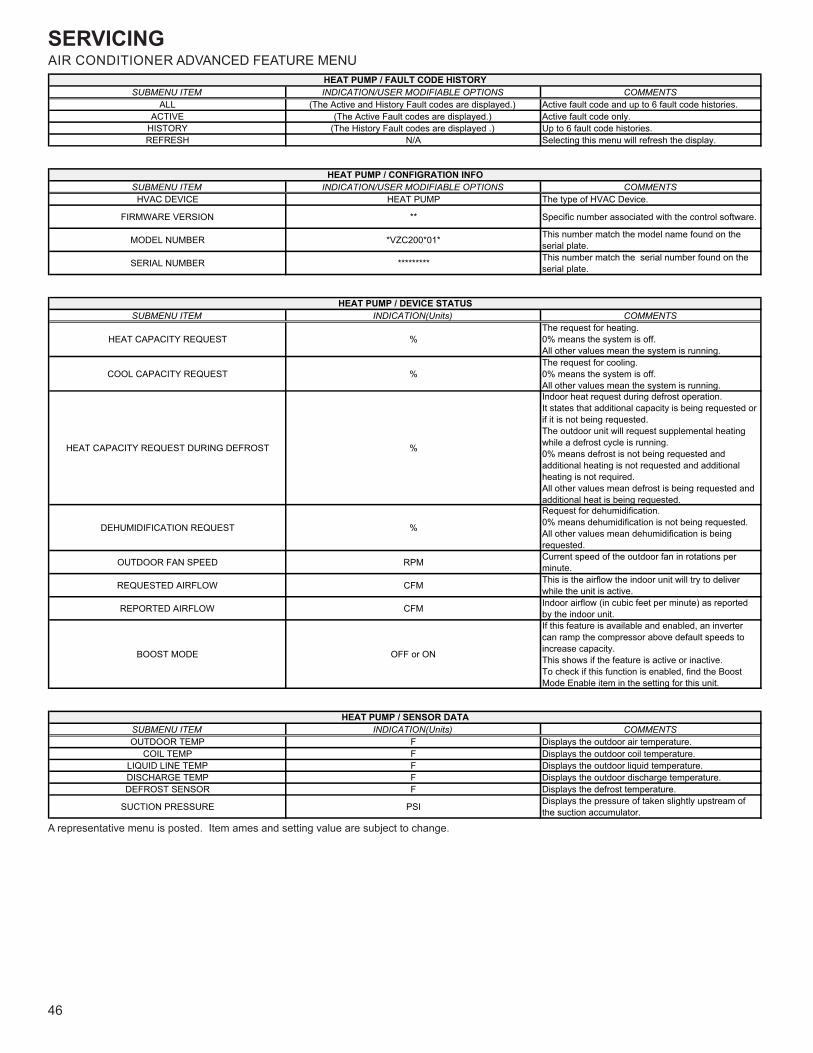
SERVICING
46
AIR CONDITIONER ADVANCED FEATURE MENU
A representative menu is posted. Item ames and setting value are subject to change.
SUBMENU ITEM INDICATION/USER MODIFIABLE OPTIONS COMMENTSALL (The Active and History Fault codes are displayed.) Active fault code and up to 6 fault code histories.
ACTIVE (The Active Fault codes are displayed.) Active fault code only.HISTORY (The History Fault codes are displayed .) Up to 6 fault code histories.REFRESH N/A Selecting this menu will refresh the display.
SUBMENU ITEM INDICATION/USER MODIFIABLE OPTIONS COMMENTSHVAC DEVICE HEAT PUMP The type of HVAC Device.
FIRMWARE VERSION ** Specific number associated with the control software.
MODEL NUMBER *VZC200*01* This number match the model name found on the serial plate.
SERIAL NUMBER ********* This number match the serial number found on the serial plate.
SUBMENU ITEM INDICATION(Units) COMMENTS
HEAT CAPACITY REQUEST %The request for heating.0% means the system is off.All other values mean the system is running.
COOL CAPACITY REQUEST %The request for cooling.0% means the system is off.All other values mean the system is running.
HEAT CAPACITY REQUEST DURING DEFROST %
Indoor heat request during defrost operation.It states that additional capacity is being requested or if it is not being requested.The outdoor unit will request supplemental heating while a defrost cycle is running.0% means defrost is not being requested and additional heating is not requested and additional heating is not required.All other values mean defrost is being requested and additional heat is being requested.
DEHUMIDIFICATION REQUEST %
Request for dehumidification.0% means dehumidification is not being requested.All other values mean dehumidification is being requested.
OUTDOOR FAN SPEED RPM Current speed of the outdoor fan in rotations per minute.
REQUESTED AIRFLOW CFM This is the airflow the indoor unit will try to deliver while the unit is active.
REPORTED AIRFLOW CFM Indoor airflow (in cubic feet per minute) as reported by the indoor unit.
BOOST MODE OFF or ON
If this feature is available and enabled, an inverter can ramp the compressor above default speeds to increase capacity.This shows if the feature is active or inactive.To check if this function is enabled, find the Boost Mode Enable item in the setting for this unit.
SUBMENU ITEM INDICATION(Units) COMMENTSOUTDOOR TEMP F Displays the outdoor air temperature.
COIL TEMP F Displays the outdoor coil temperature.LIQUID LINE TEMP F Displays the outdoor liquid temperature.DISCHARGE TEMP F Displays the outdoor discharge temperature.DEFROST SENSOR F Displays the defrost temperature.
SUCTION PRESSURE PSI Displays the pressure of taken slightly upstream of the suction accumulator.
HEAT PUMP / FAULT CODE HISTORY
HEAT PUMP / CONFIGRATION INFO
HEAT PUMP / DEVICE STATUS
HEAT PUMP / SENSOR DATA
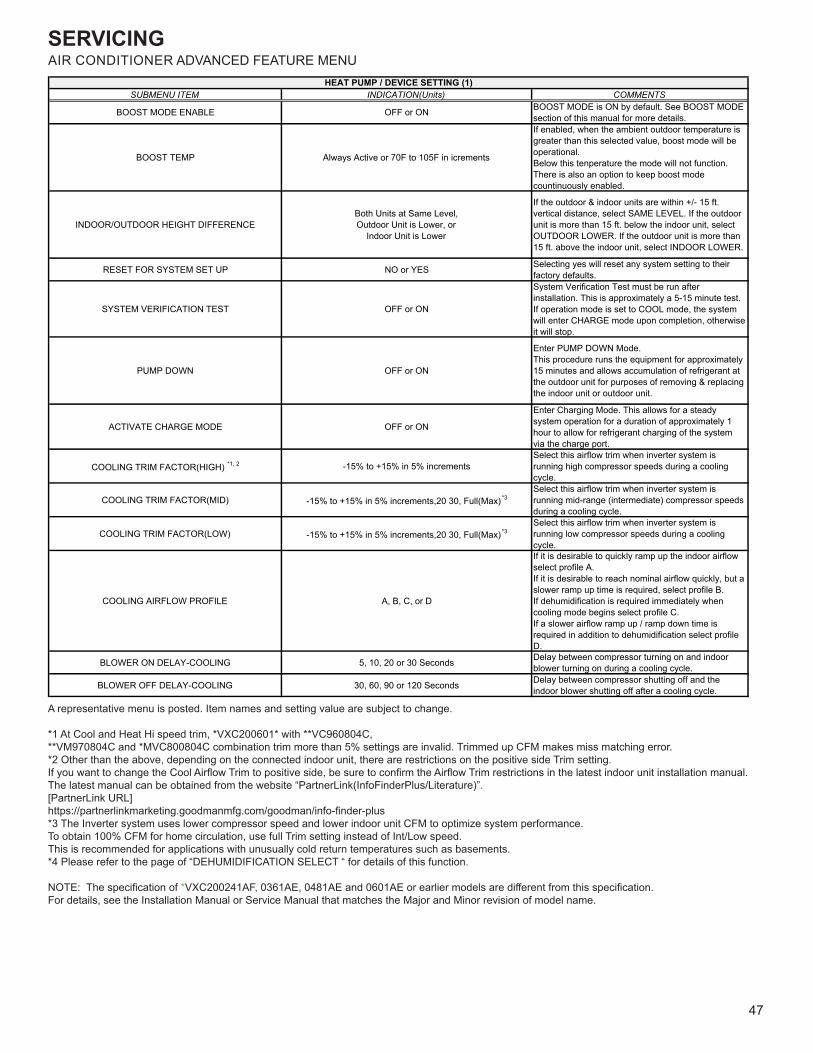
SERVICING
47
AIR CONDITIONER ADVANCED FEATURE MENU
A representative menu is posted. Item names and setting value are subject to change.
*1 At Cool and Heat Hi speed trim, *VXC200601* with **VC960804C,**VM970804C and *MVC800804C combination trim more than 5% settings are invalid. Trimmed up CFM makes miss matching error.*2 Other than the above, depending on the connected indoor unit, there are restrictions on the positive side Trim setting.If you want to change the Cool Airflow Trim to positive side, be sure to confirm the Airflow Trim restrictions in the latest indoor unit installation manual.The latest manual can be obtained from the website “PartnerLink(InfoFinderPlus/Literature)”.[PartnerLink URL]https://partnerlinkmarketing.goodmanmfg.com/goodman/info-finder-plus*3 The Inverter system uses lower compressor speed and lower indoor unit CFM to optimize system performance.To obtain 100% CFM for home circulation, use full Trim setting instead of Int/Low speed.This is recommended for applications with unusually cold return temperatures such as basements.*4 Please refer to the page of “DEHUMIDIFICATION SELECT “ for details of this function.
NOTE: The specification of *VXC200241AF, 0361AE, 0481AE and 0601AE or earlier models are different from this specification.For details, see the Installation Manual or Service Manual that matches the Major and Minor revision of model name.
SUBMENU ITEM INDICATION(Units) COMMENTS
BOOST MODE ENABLE OFF or ON BOOST MODE is ON by default. See BOOST MODE section of this manual for more details.
BOOST TEMP Always Active or 70F to 105F in icrements
If enabled, when the ambient outdoor temperature is greater than this selected value, boost mode will be operational.Below this tenperature the mode will not function.There is also an option to keep boost mode countinuously enabled.
INDOOR/OUTDOOR HEIGHT DIFFERENCEBoth Units at Same Level, Outdoor Unit is Lower, or
Indoor Unit is Lower
If the outdoor & indoor units are within +/- 15 ft. vertical distance, select SAME LEVEL. If the outdoor unit is more than 15 ft. below the indoor unit, select OUTDOOR LOWER. If the outdoor unit is more than 15 ft. above the indoor unit, select INDOOR LOWER.
RESET FOR SYSTEM SET UP NO or YES Selecting yes will reset any system setting to their factory defaults.
SYSTEM VERIFICATION TEST OFF or ON
System Verification Test must be run after installation. This is approximately a 5-15 minute test. If operation mode is set to COOL mode, the system will enter CHARGE mode upon completion, otherwise it will stop.
PUMP DOWN OFF or ON
Enter PUMP DOWN Mode. This procedure runs the equipment for approximately 15 minutes and allows accumulation of refrigerant atthe outdoor unit for purposes of removing & replacing the indoor unit or outdoor unit.
ACTIVATE CHARGE MODE OFF or ON
Enter Charging Mode. This allows for a steady system operation for a duration of approximately 1 hour to allow for refrigerant charging of the system via the charge port.
COOLING TRIM FACTOR(HIGH) *1, 2 -15% to +15% in 5% incrementsSelect this airflow trim when inverter system is running high compressor speeds during a cooling cycle.
COOLING TRIM FACTOR(MID) -15% to +15% in 5% increments,20 30, Full(Max)*3Select this airflow trim when inverter system is running mid-range (intermediate) compressor speeds during a cooling cycle.
COOLING TRIM FACTOR(LOW) -15% to +15% in 5% increments,20 30, Full(Max)*3Select this airflow trim when inverter system is running low compressor speeds during a cooling cycle.
COOLING AIRFLOW PROFILE A, B, C, or D
If it is desirable to quickly ramp up the indoor airflow select profile A.If it is desirable to reach nominal airflow quickly, but a slower ramp up time is required, select profile B.If dehumidification is required immediately when cooling mode begins select profile C.If a slower airflow ramp up / ramp down time is required in addition to dehumidification select profile D.
BLOWER ON DELAY-COOLING 5, 10, 20 or 30 Seconds Delay between compressor turning on and indoor blower turning on during a cooling cycle.
BLOWER OFF DELAY-COOLING 30, 60, 90 or 120 Seconds Delay between compressor shutting off and the indoor blower shutting off after a cooling cycle.
HEAT PUMP / DEVICE SETTING (1)
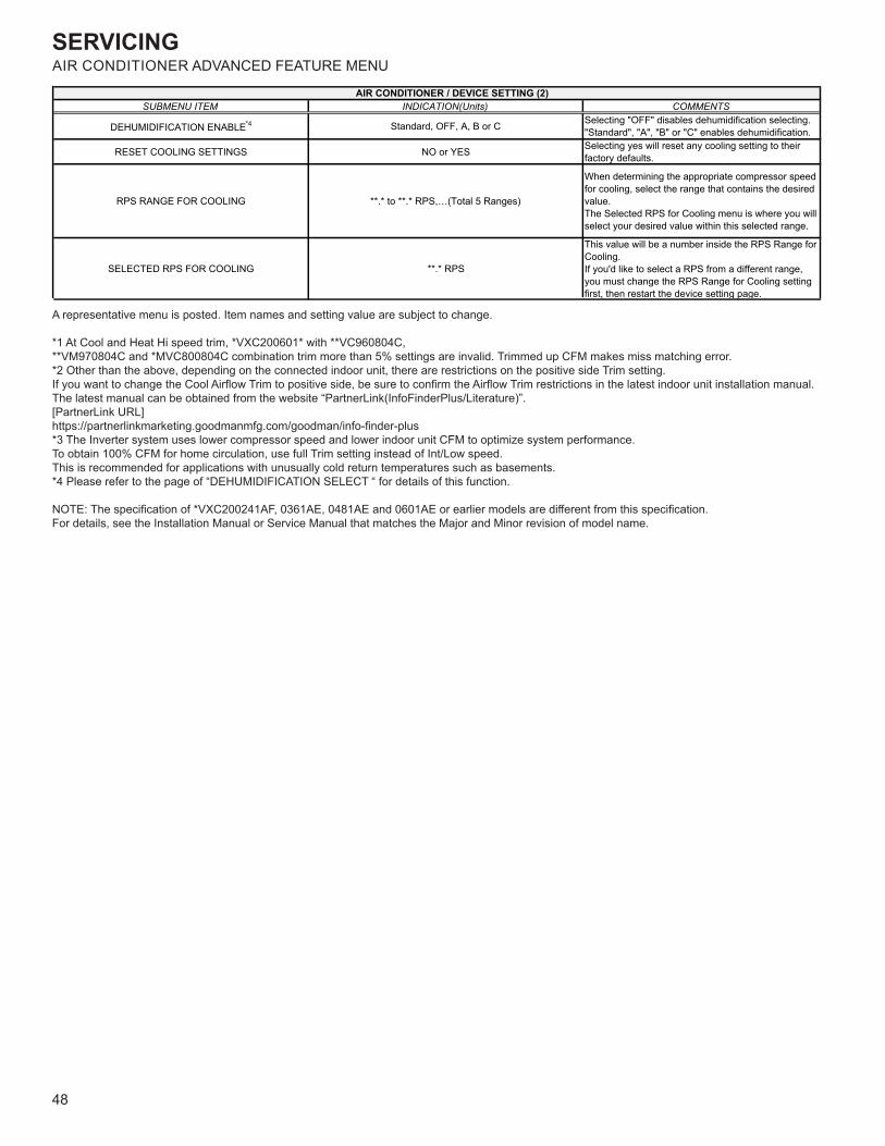
SERVICING
48
AIR CONDITIONER ADVANCED FEATURE MENU
A representative menu is posted. Item names and setting value are subject to change.
*1 At Cool and Heat Hi speed trim, *VXC200601* with **VC960804C,**VM970804C and *MVC800804C combination trim more than 5% settings are invalid. Trimmed up CFM makes miss matching error.*2 Other than the above, depending on the connected indoor unit, there are restrictions on the positive side Trim setting.If you want to change the Cool Airflow Trim to positive side, be sure to confirm the Airflow Trim restrictions in the latest indoor unit installation manual.The latest manual can be obtained from the website “PartnerLink(InfoFinderPlus/Literature)”.[PartnerLink URL]https://partnerlinkmarketing.goodmanmfg.com/goodman/info-finder-plus*3 The Inverter system uses lower compressor speed and lower indoor unit CFM to optimize system performance.To obtain 100% CFM for home circulation, use full Trim setting instead of Int/Low speed.This is recommended for applications with unusually cold return temperatures such as basements.*4 Please refer to the page of “DEHUMIDIFICATION SELECT “ for details of this function.
NOTE: The specification of *VXC200241AF, 0361AE, 0481AE and 0601AE or earlier models are different from this specification.For details, see the Installation Manual or Service Manual that matches the Major and Minor revision of model name.
SUBMENU ITEM INDICATION(Units) COMMENTS
DEHUMIDIFICATION ENABLE*4 Standard, OFF, A, B or C Selecting "OFF" disables dehumidification selecting."Standard", "A", "B" or "C" enables dehumidification.
RESET COOLING SETTINGS NO or YES Selecting yes will reset any cooling setting to their factory defaults.
RPS RANGE FOR COOLING **.* to **.* RPS,…(Total 5 Ranges)
When determining the appropriate compressor speed for cooling, select the range that contains the desired value.The Selected RPS for Cooling menu is where you will select your desired value within this selected range.
SELECTED RPS FOR COOLING **.* RPS
This value will be a number inside the RPS Range for Cooling.If you'd like to select a RPS from a different range, you must change the RPS Range for Cooling setting first, then restart the device setting page.
AIR CONDITIONER / DEVICE SETTING (2)
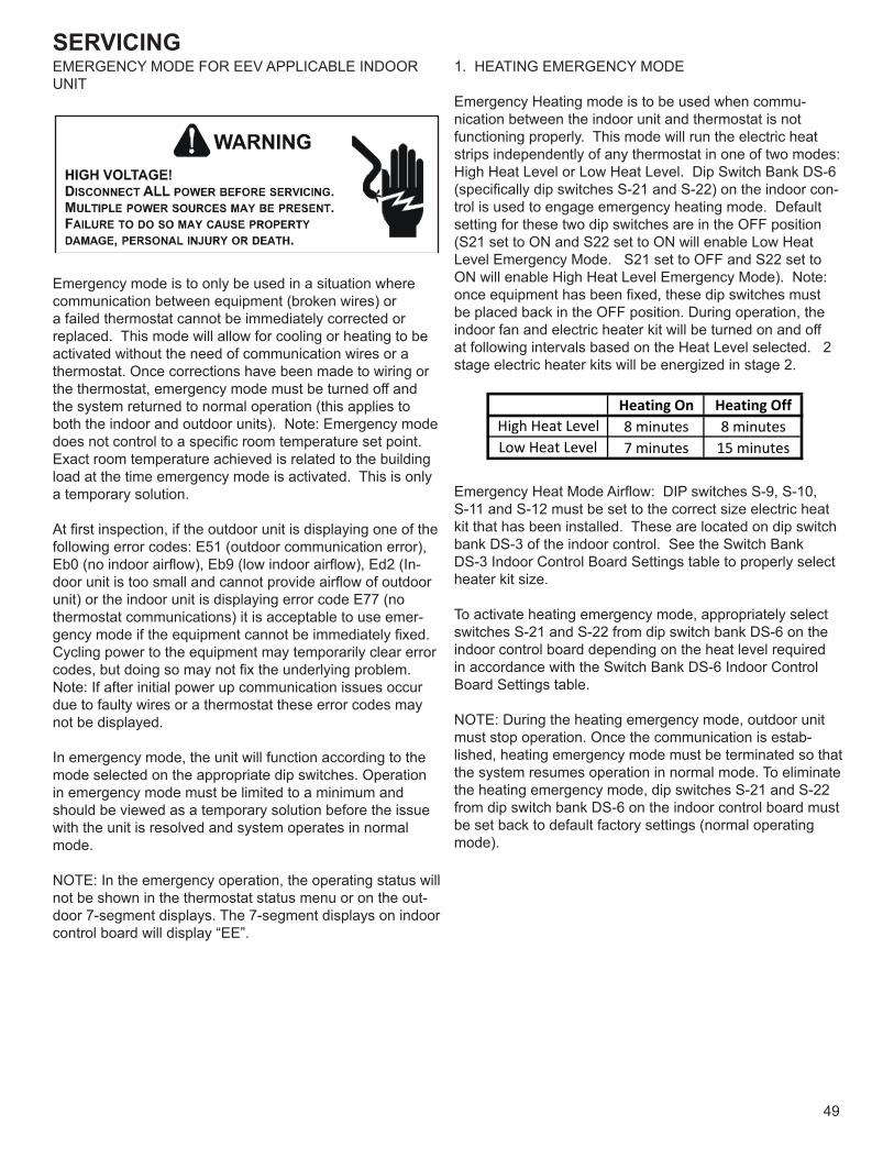
SERVICING
49
EMERGENCY MODE FOR EEV APPLICABLE INDOOR UNIT
Emergency mode is to only be used in a situation where communication between equipment (broken wires) or a failed thermostat cannot be immediately corrected or replaced. This mode will allow for cooling or heating to be activated without the need of communication wires or a thermostat. Once corrections have been made to wiring or the thermostat, emergency mode must be turned off and the system returned to normal operation (this applies to both the indoor and outdoor units). Note: Emergency mode does not control to a specific room temperature set point. Exact room temperature achieved is related to the building load at the time emergency mode is activated. This is only a temporary solution.
At first inspection, if the outdoor unit is displaying one of the following error codes: E51 (outdoor communication error), Eb0 (no indoor airflow), Eb9 (low indoor airflow), Ed2 (In-door unit is too small and cannot provide airflow of outdoor unit) or the indoor unit is displaying error code E77 (no thermostat communications) it is acceptable to use emer-gency mode if the equipment cannot be immediately fixed. Cycling power to the equipment may temporarily clear error codes, but doing so may not fix the underlying problem. Note: If after initial power up communication issues occur due to faulty wires or a thermostat these error codes may not be displayed.
In emergency mode, the unit will function according to the mode selected on the appropriate dip switches. Operation in emergency mode must be limited to a minimum and should be viewed as a temporary solution before the issue with the unit is resolved and system operates in normal mode.
NOTE: In the emergency operation, the operating status will not be shown in the thermostat status menu or on the out-door 7-segment displays. The 7-segment displays on indoor control board will display “EE”.
1. HEATING EMERGENCY MODE
Emergency Heating mode is to be used when commu-nication between the indoor unit and thermostat is not functioning properly. This mode will run the electric heat strips independently of any thermostat in one of two modes: High Heat Level or Low Heat Level. Dip Switch Bank DS-6 (specifically dip switches S-21 and S-22) on the indoor con-trol is used to engage emergency heating mode. Default setting for these two dip switches are in the OFF position (S21 set to ON and S22 set to ON will enable Low Heat Level Emergency Mode. S21 set to OFF and S22 set to ON will enable High Heat Level Emergency Mode). Note: once equipment has been fixed, these dip switches must be placed back in the OFF position. During operation, the indoor fan and electric heater kit will be turned on and off at following intervals based on the Heat Level selected. 2 stage electric heater kits will be energized in stage 2.
Heating On Heating Off8 minutes 8 minutes7 minutes 15 minutes
High Heat LevelLow Heat Level
Emergency Heat Mode Airflow: DIP switches S-9, S-10, S-11 and S-12 must be set to the correct size electric heat kit that has been installed. These are located on dip switch bank DS-3 of the indoor control. See the Switch Bank DS-3 Indoor Control Board Settings table to properly select heater kit size.
To activate heating emergency mode, appropriately select switches S-21 and S-22 from dip switch bank DS-6 on the indoor control board depending on the heat level required in accordance with the Switch Bank DS-6 Indoor Control Board Settings table.
NOTE: During the heating emergency mode, outdoor unit must stop operation. Once the communication is estab-lished, heating emergency mode must be terminated so that the system resumes operation in normal mode. To eliminate the heating emergency mode, dip switches S-21 and S-22 from dip switch bank DS-6 on the indoor control board must be set back to default factory settings (normal operating mode).
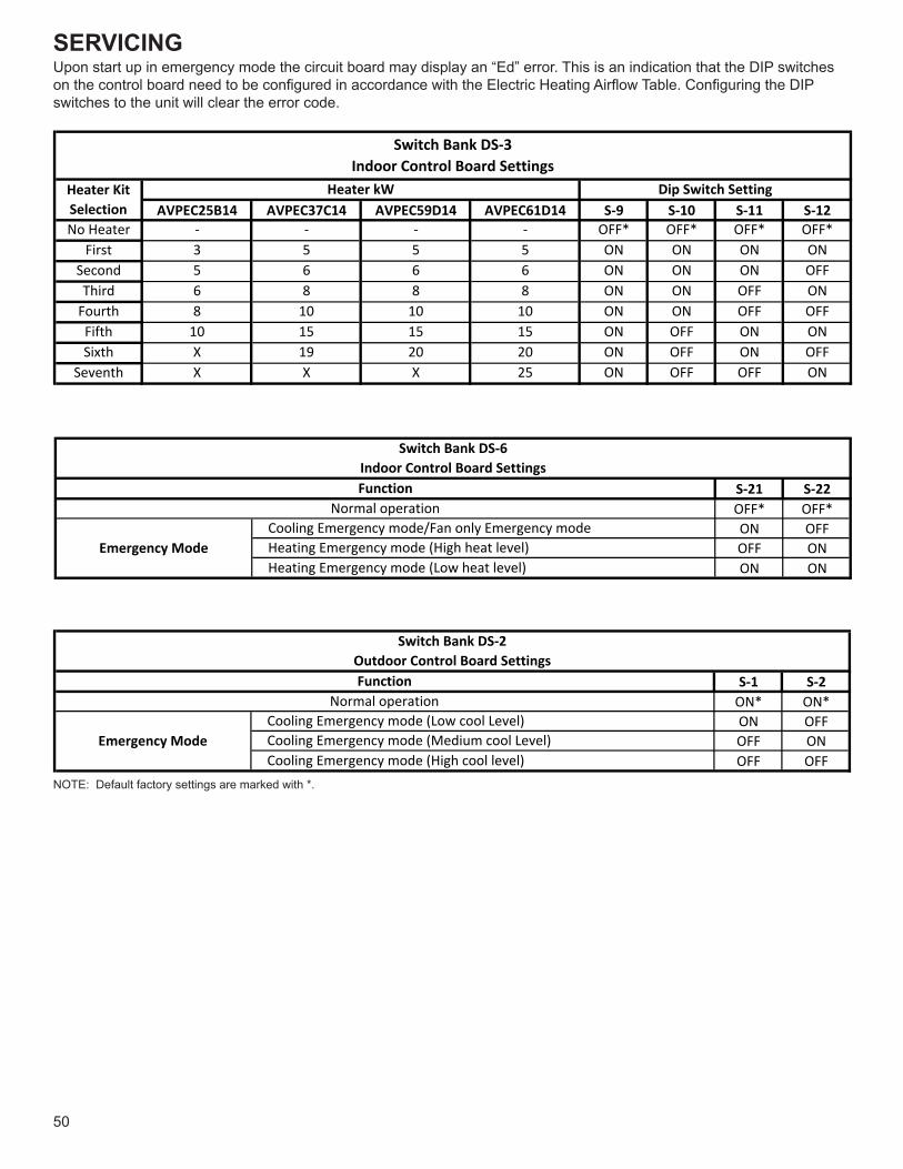
SERVICING
50
Upon start up in emergency mode the circuit board may display an “Ed” error. This is an indication that the DIP switches on the control board need to be configured in accordance with the Electric Heating Airflow Table. Configuring the DIP switches to the unit will clear the error code.
AVPEC25B14 AVPEC37C14 AVPEC59D14 AVPEC61D14 S-9 S-10 S-11 S-12No Heater - - - - OFF* OFF* OFF* OFF*
First 3 5 5 5 ON ON ON ONSecond 5 6 6 6 ON ON ON OFFThird 6 8 8 8 ON ON OFF ON
Fourth 8 10 10 10 ON ON OFF OFFFifth 10 15 15 15 ON OFF ON ONSixth X 19 20 20 ON OFF ON OFF
Seventh X X X 25 ON OFF OFF ON
Switch Bank DS-3Indoor Control Board Settings
Heater Kit Selection
Heater kW Dip Switch Setting
S-21 S-22OFF* OFF*ON OFFOFF ONON ON
Emergency Mode
FunctionNormal operation
Cooling Emergency mode/Fan only Emergency mode Heating Emergency mode (High heat level) Heating Emergency mode (Low heat level)
Switch Bank DS-6Indoor Control Board Settings
S-1 S-2ON* ON*ON OFFOFF ONOFF OFF
Cooling Emergency mode (Medium cool Level) Cooling Emergency mode (High cool level)
Switch Bank DS-2Outdoor Control Board Settings
Emergency Mode
FunctionNormal operation
Cooling Emergency mode (Low cool Level)
NOTE: Default factory settings are marked with *.

SERVICING
51
2. COOLING EMERGENCY MODECooling emergency mode is to be used when communica-tion between the indoor and outdoor units is not functioning properly and temporary cooling operation is required. This mode enables the outdoor unit and indoor unit to run inde-pendently of each other. There are two key steps to setup Cooling Emergency Mode.
a) Select the appropriate airflow on the indoor unit and enable emergency indoor airflow operation (using Dip switches S-13 and S-14 of Switch Bank DS-4 on the indoor unit to select desired 25%, 50%, 75% or 100% airflow. In addition, set switch bank DS-6 dip switches S-21 to ON and S-22 to OFF enabling emergency indoor fan).
b) Select the desired cooling level at the outdoor unit (there are 3 levels available: Low Cool Level, Medium Cool Level, High Cool Level selectable by dip switch bank DS-2 on the outdoor unit). See Dip Switch Position DS2-1 and DS2-2 Table for cooling level selection.
Function Value SW13 SW14 SW15 SW16
25 OFF OFF - -
50 ON* OFF* - -
75 OFF ON ON* -
100 ON ON OFF -
Switch Bank DS-4Indoor Fan Settings
Fan OnlySpeed %
During operation the indoor unit will provide constant airflow as selected (even if the compressor has stopped). The indoor unit will continue to operate the electronic expansion valve for refrigerant super heat control and the compressor will cycle at the interval selected by dip switch bank DS-2.
DS2-1 DS2-2
ON ON Normal Operation
ON OFFEmergency Mode(Low Cool Level)
OFF ONEmergency Mode
(Medium Cool Level)
OFF OFFEmergency Mode(High Cool Level)
Dip Switch PositionFunction
ON time OFF timeAvg.
Run Time
Low CoolLevel
7 minutes 15 minutes 30%
MediumCool Level
8 minutes 10 minutes 50%
High CoolLevel
15 minutes 6 minutes 70%
Note: This mode does not require a thermostat. Any ther-mostat requests will be ignored while in emergency opera-tion.
NOTE: Set indoor DS-4 (Indoor fan setting) and DS-6 (In-door emergency mode enable) before setting outdoor DS-2 dip switch settings. Otherwise, the compressor may be damaged in operation.
Note: When proper communication is established, these switches must be returned to default settings
The compressor speed will automatically adjust based on the outdoor ambient temperature. If ambient temperature is higher than 95 ° F, the outdoor unit can operate at 100% compressor speed. If ambient temperature is lower than 70° F, the unit will run at 50% compressor speed. Between 95 ° F and 70 ° F, the compressor speed will adjust linearly as shown.
100%
50%
70F 95F
CompressorCapacity
Ambienttemp
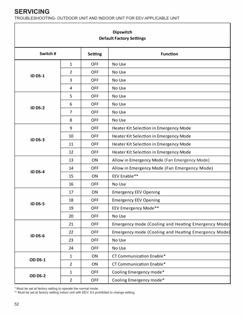
SERVICING
52
TROUBLESHOOTING- OUTDOOR UNIT AND INDOOR UNIT FOR EEV APPLICABLE UNIT
Se�ng Func�on
1 OFF No Use
2 OFF No Use
3 OFF No Use
4 OFF No Use
5 OFF No Use
6 OFF No Use
7 OFF No Use
8 OFF No Use
9 OFF Heater Kit Selec�on in Emergency Mode
10 OFF Heater Kit Selec�on in Emergency Mode
11 OFF Heater Kit Selec�on in Emergency Mode
12 OFF Heater Kit Selec�on in Emergency Mode
13 ON Allow in Emergency Mode (Fan Emergency Mode)
14 OFF Allow in Emergency Mode (Fan Emergency Mode)
15 ON EEV Enable**
16 OFF No Use
17 ON Emergency EEV Opening
18 OFF Emergency EEV Opening
19 OFF EEV Emergency Mode**
20 OFF No Use
21 OFF Emergency mode (Cooling and Hea�ng Emergency Mode)
22 OFF Emergency mode (Cooling and Hea�ng Emergency Mode)
23 OFF No Use
24 OFF No Use
1 ON CT Communica�on Enable*
2 ON CT Communica�on Enable*
1 OFF Cooling Emergency mode*
2 OFF Cooling Emergency mode*
ID DS-5
ID DS-6
OD DS-1
OD DS-2
Switch #
Dipswitch Default Factory Se�ngs
ID DS-1
ID DS-2
ID DS-3
ID DS-4
* Must be set at factory setting to operate the normal mode.** Must be set at factory setting indoor unit with EEV. It’s prohibited to change setting.
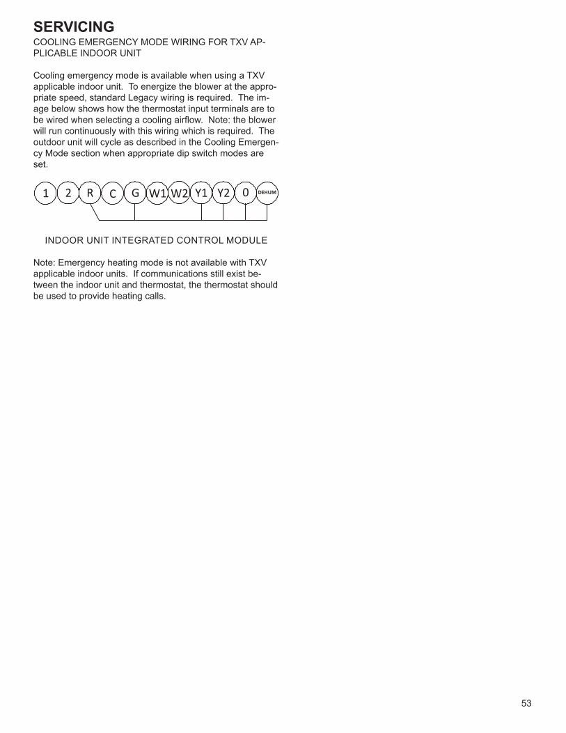
SERVICING
53
COOLING EMERGENCY MODE WIRING FOR TXV AP-PLICABLE INDOOR UNIT
Cooling emergency mode is available when using a TXV applicable indoor unit. To energize the blower at the appro-priate speed, standard Legacy wiring is required. The im-age below shows how the thermostat input terminals are to be wired when selecting a cooling airflow. Note: the blower will run continuously with this wiring which is required. The outdoor unit will cycle as described in the Cooling Emergen-cy Mode section when appropriate dip switch modes are set.
1 2 R C G W1 W2 Y1 Y2 0 DEHUM
INDOOR UNIT INTEGRATED CONTROL MODULE
Note: Emergency heating mode is not available with TXV applicable indoor units. If communications still exist be-tween the indoor unit and thermostat, the thermostat should be used to provide heating calls.
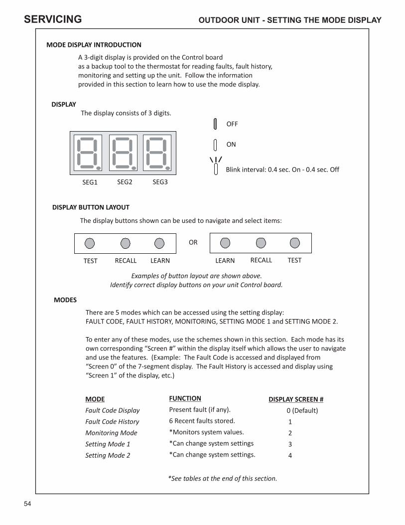
SERVICING
54
MODE DISPLAY INTRODUCTION
SEG1 SEG2 SEG3
TEST RECALL LEARN
A 3-digit display is provided on the Control boardas a backup tool to the thermostat for reading faults, fault history,monitoring and setting up the unit. Follow the informationprovided in this section to learn how to use the mode display.
DISPLAYThe display consists of 3 digits.
DISPLAY BUTTON LAYOUT
The display buttons shown can be used to navigate and select items:
MODES
There are 5 modes which can be accessed using the setting display: and
To enter any of these modes, use the schemes shown in this section. Each mode has itsown corresponding “Screen #” within the display itself which allows the user to navigateand use the features. (Example: The Fault Code is accessed and displayed from“Screen 0” of the 7-segment display. The Fault History is accessed and display using“Screen 1” of the display, etc.)
FAULT CODE, FAULT HISTORY, MONITORING, SETTING MODE 1 SETTING MODE 2.
MODEFault Code DisplayFault Code HistoryMonitoring ModeSetting Mode 1Setting Mode 2
FUNCTIONPresent fault (if any).6 Recent faults stored.*Monitors system values.*Can change system *Can change system settings.
settings
DISPLAY SCREEN # 0 (Default) 1 2 3 4
OFF
ON
Blink interval: 0.4 sec. On - 0.4 sec. Off
*See tables at the end of this section.
TESTRECALLLEARN
OR
Examples of button layout are shown above.Identify correct display buttons on your unit Control board.
OUTDOOR UNIT - SETTING THE MODE DISPLAY
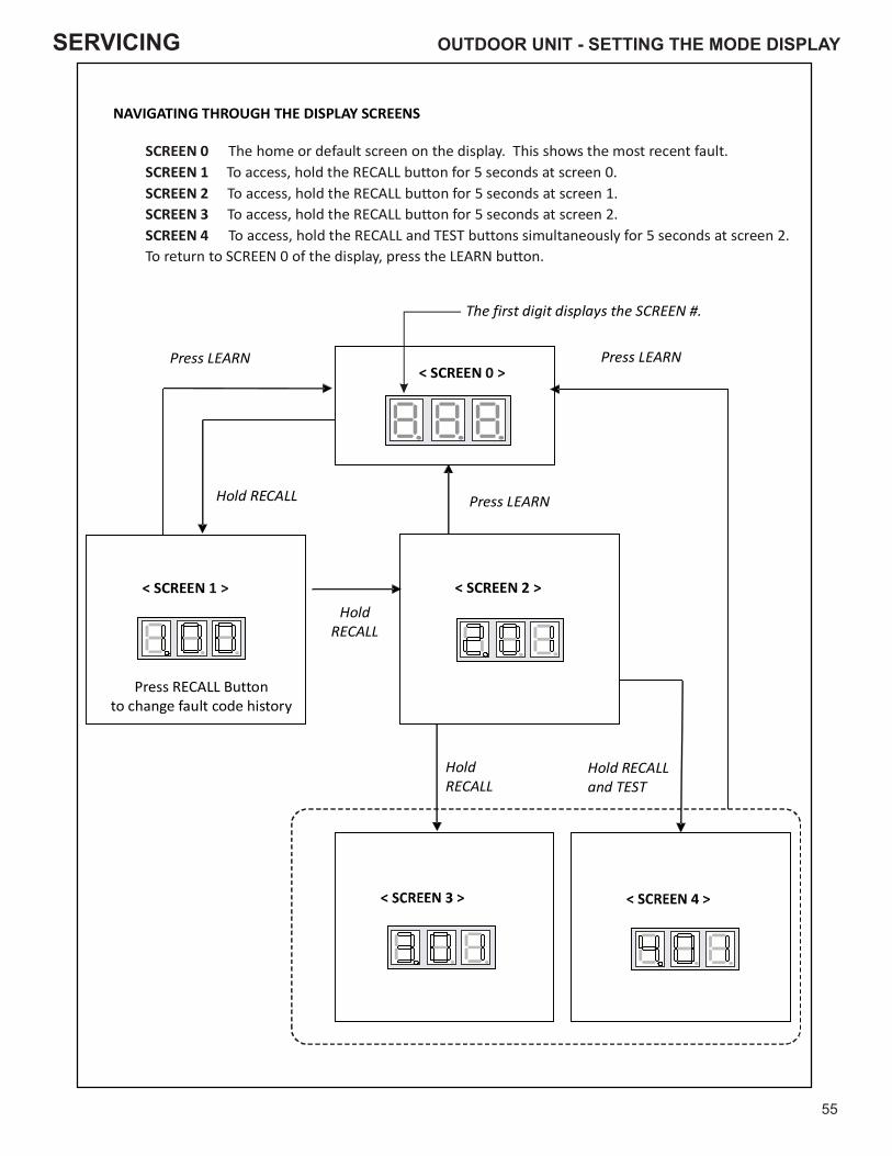
SERVICING
55
< SCREEN 0 >
< SCREEN 1 > < SCREEN 2 >
Press RECALL Buttonto change fault code history
Hold RECALLand TEST
NAVIGATING THROUGH THE DISPLAY SCREENS
SCREEN 0 SCREEN 1 SCREEN 2 SCREEN 3 SCREEN 4
The home or default screen on the display. This shows the most recent fault.To access, hold the RECALL button for 5 seconds at screen 0.To access, hold the RECALL button for 5 seconds at screen 1.To access, hold the RECALL button .To access, hold the RECALL and TEST buttons simultaneously
To return to SCREEN 0 of the display, press the LEARN button.
for 5 seconds at screen 2for 5 seconds at screen 2.
The first digit displays the SCREEN #.
Hold RECALL
Press LEARN Press LEARN
Press LEARN
HoldRECALL
HoldRECALL
OUTDOOR UNIT - SETTING THE MODE DISPLAY
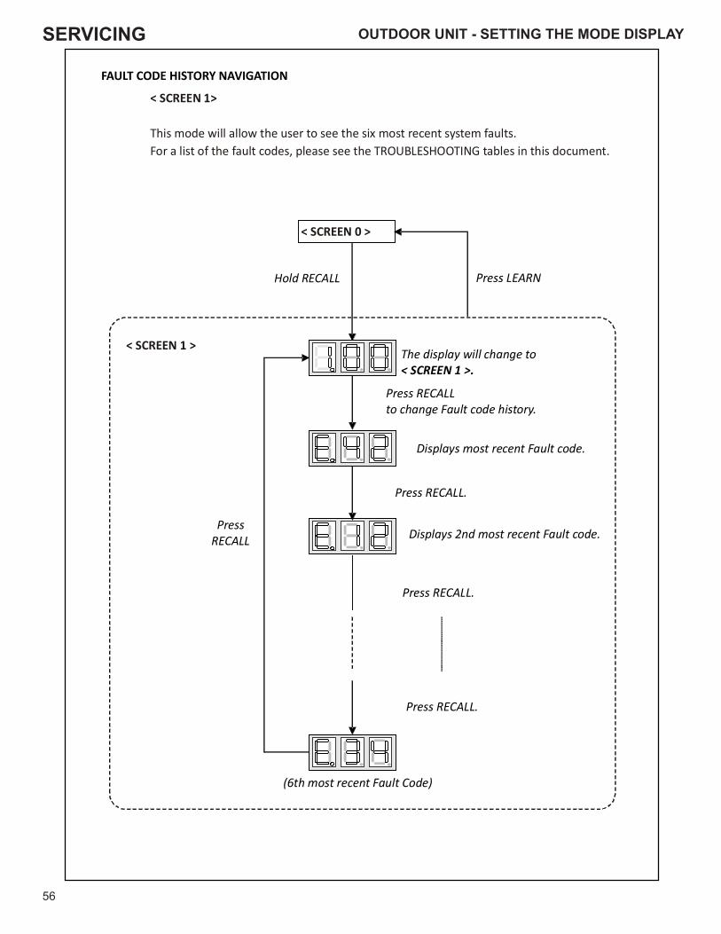
SERVICING
56
Press RECALLto change Fault code history.
Displays most recent Fault code.
Press LEARN
FAULT CODE HISTORY NAVIGATION
< SCREEN
This mode will allow the user to see the six most recent system faults.For a list of the fault codes, please see the TROUBLESHOOTING tables in this document.
1>
< SCREEN 0 >
< SCREEN 1 >The display will change to< SCREEN 1 >.
Displays 2nd most recent Fault code.
(6th most recent Fault Code)
Hold RECALL
Press RECALL.
Press RECALL.
Press RECALL.
PressRECALL
OUTDOOR UNIT - SETTING THE MODE DISPLAY
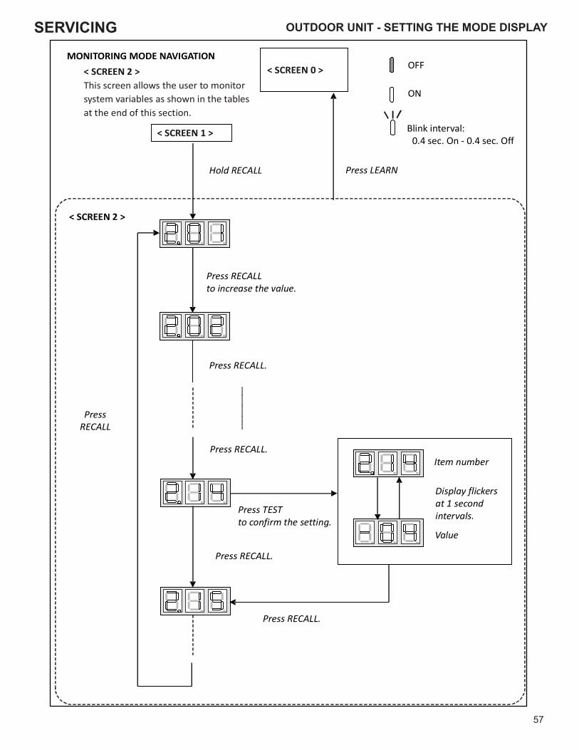
SERVICING
57
< SCREEN 2 >
Press LEARN
< SCREEN 0 >
< SCREEN 1 >
Press RECALL to increase the value.
Press TESTto confirm the setting.
Press RECALL.
PressRECALL
Item number
Display flickersat 1 secondintervals.
Value
MONITORING MODE NAVIGATION< SCRThis screen allows the user to monitorsystem variables as shown in the tablesat the end of this section.
EEN 2 > OFF
ON
Blink interval:0.4 sec. On - 0.4 sec. Off
Hold RECALL
Press RECALL.
Press RECALL.
Press RECALL.
OUTDOOR UNIT - SETTING THE MODE DISPLAY
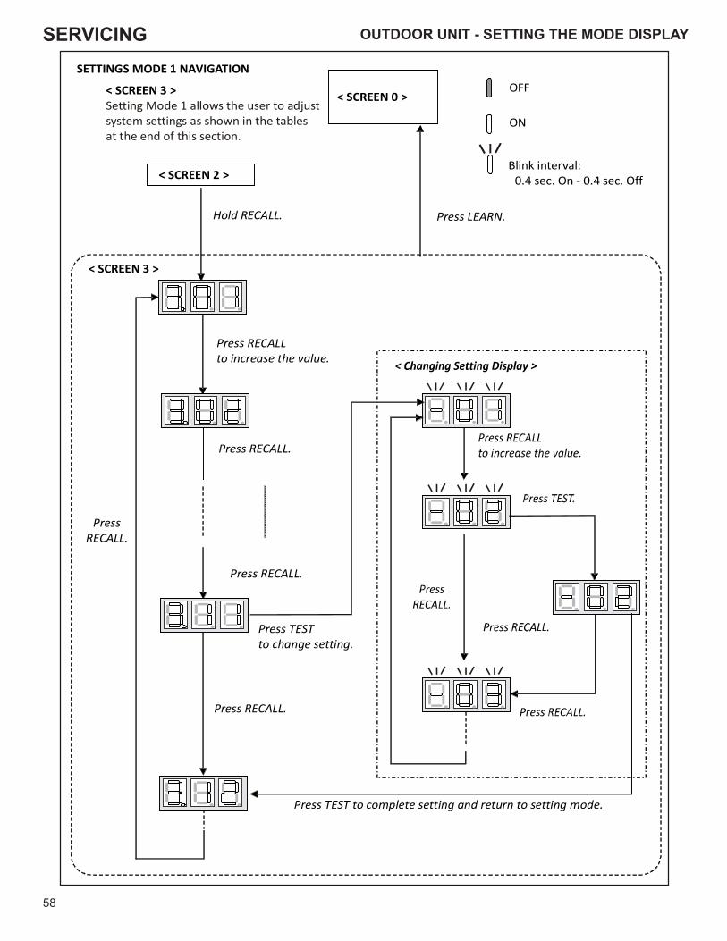
SERVICING
58
Hold RECALL.
SETTINGS MODE 1 NAVIGATION
< SCREEN 3 >Setting Mode 1 allows the user to adjustsystem settings as shown in the tablesat the end of this section.
< SCREEN 0 >
PressRECALL.
Press RECALLto increase the value.
Press TESTto change setting.
Press RECALL.
Press TEST to complete setting and return to setting mode.
< SCREEN 2 >
Press LEARN.
< SCREEN 3 >
Press RECALL.
Press RECALL.
OFF
ON
Blink interval:0.4 sec. On - 0.4 sec. Off
OUTDOOR UNIT - SETTING THE MODE DISPLAY
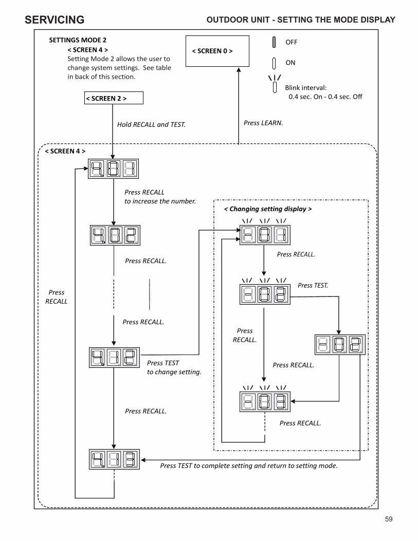
SERVICING
59
Press LEARN.
< Changing setting display >
Hold RECALL and TEST.
< SCREEN 4 >
SETTINGS MODE 2
< SCREEN 2 >
Press RECALLto increase the number.
Press RECALL.
Press TESTto change setting.
PressRECALL
Press TEST to complete setting and return to setting mode.
PressRECALL.
Press RECALL.
Press RECALL.
< SCREEN 0 >OFF
ON
Blink interval:0.4 sec. On - 0.4 sec. Off
Press RECALL.
Press RECALL.
< SCREEN 4 >Setting Mode 2 allows the user tochange system settings. See tablein back of this section.
OUTDOOR UNIT - SETTING THE MODE DISPLAY

SERVICING
60
SCREEN 0 (Display FAULT CODE)
SettingNo. Contents Notes
1 Fault code (present)
SCREEN 1 (Display FAULT CODES)
SettingNo. Contents Notes
1 Fault code (latest) Latest
2 Fault code (2nd) 2nd
3 Fault code (3rd) 3rd
4 Fault code (4th) 4th
5 Fault code (5th) 5th
6 Fault code (6th) 6th
SCREEN 2 (MONITOR MODE)
SettingNo. Contents Notes
1 Compressor operation time unit:hr (Multiply by 200,)
2 Operation code
0: Stop1: Cooling Start-up2: Heating Start-up3: Oil Return Operation4: Heating Operation5: Defrost Operation6: Cooling Operation
3 Compressor Reduction Mode 0:OFF,1:ON
4 % demand unit:%(Cut off the decimal first place.)
5 act % demand unit:%(Cut off the decimal first place.)
6 Requested ID CFM unit:CFM (Multiply by 10)
7 Reported ID CFM unit:CFM (Multiply by 10)
8 Outdoor FAN RPM unit:RPM (Multiply by 10)
9 Ta (Outdoor Air Temperature) unit:F
10 Td (Discharge Temperature) unit:F
11 Tm (Outdoor Coil Temperature) unit:F
12 Tb (Defrost Sensor Temperature) unit:F
13 Tl (Liquid Temperature) unit:F
14 Pressure Sensor unit:PSI
7-SEGMENT DISPLAY
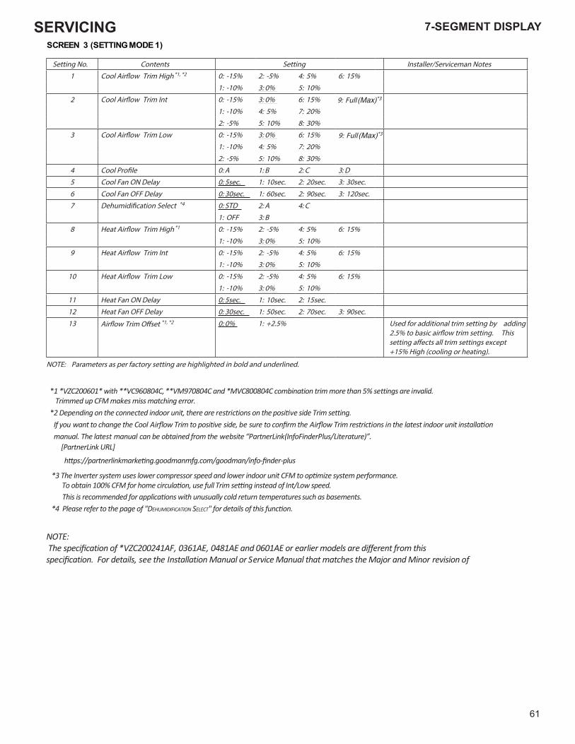
SERVICING
61
SCREEN 3 (SETTING MODE 1)SCREEN 3 (SETTING MODE 1)
Setting No. Contents Setting Installer/Serviceman Notes
1 Cool Air�ow Trim High *1, *2 0: -15% 2: -5% 4: 5% 6: 15%
1: -10% 3: 0% 5: 10%
2 Cool Air�ow Trim Int 0: -15% 3: 0% 6: 15% 9: Full *3
1: -10% 4: 5% 7: 20%
2: -5% 5: 10% 8: 30%
3 Cool Air�ow Trim Low 0: -15% 3: 0% 6: 15% 9: Full *3
1: -10% 4: 5% 7: 20%
2: -5% 5: 10% 8: 30%
4 Cool Pro�le 0: A 1: B 2: C 3: D
5 Cool Fan ON Delay 0: 5sec. 1: 10sec. 2: 20sec. 3: 30sec.
6 Cool Fan OFF Delay 0: 30sec. 1: 60sec. 2: 90sec. 3: 120sec.
7 Dehumidi�cation Select *4 0: STD 2: A 4: C
1: OFF 3: B
8 Heat Air�ow Trim High *1 0: -15% 2: -5% 4: 5% 6: 15%
1: -10% 3: 0% 5: 10%
9 Heat Air�ow Trim Int 0: -15% 2: -5% 4: 5% 6: 15%
1: -10% 3: 0% 5: 10%
10 Heat Air�ow Trim Low 0: -15% 2: -5% 4: 5% 6: 15%
1: -10% 3: 0% 5: 10%
11 Heat Fan ON Delay 0: 5sec. 1: 10sec. 2: 15sec.
12 Heat Fan OFF Delay 0: 30sec. 1: 50sec. 2: 70sec. 3: 90sec.
13 Air�ow Trim O�set *1, *2 0: 0% 1: +2.5% Used for additional trim setting by adding 2.5% to basic air�ow trim setting. This setting a�ects all trim settings except +15% High (cooling or heating).
NOTE: Parameters as per factory setting are highlighted in bold and underlined.
*1 *VZC200601* with **VC960804C, **VM970804C and *MVC800804C combination trim more than 5% settings are invalid. Trimmed up CFM makes miss matching error.
*2 Depending on the connected indoor unit, there are restrictions on the positive side Trim setting.If you want to change the Cool Airflow Trim to positive side, be sure to confirm the Airflow Trim restrictions in the latest indoor unit installation manual. The latest manual can be obtained from the website “PartnerLink(InfoFinderPlus/Literature)”.
[PartnerLink URL]
https://partnerlinkmarketing.goodmanmfg.com/goodman/info-finder-plus
*3 The Inverter system uses lower compressor speed and lower indoor unit CFM to optimize system performance.
*4 Please refer to the page of "DEHUMIDIFICATION SELECT" for details of this function.
To obtain 100% CFM for home circulation, use full Trim setting instead of Int/Low speed. This is recommended for applications with unusually cold return temperatures such as basements.
NOTE: The specification of *VZC200241AF, 0361AE, 0481AE and 0601AE or earlier models are different from this specification. For details, see the Installation Manual or Service Manual that matches the Major and Minor revision of model name.
7-SEGMENT DISPLAY 7-SEGMENT DISPLAY
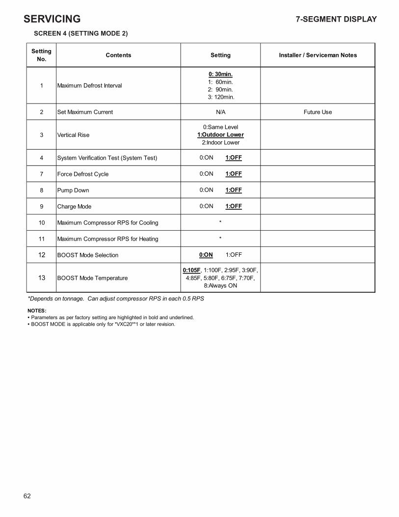
CTK04 ADDENDUMSERVICING
62
SCREEN 4 (SETTING MODE 2)
SettingNo. setoN namecivreS / rellatsnIgnitteSstnetnoC
1 Maximum Defrost Interval
0: 30min.1: 60min.2: 90min. 3: 120min.
esU erutuFA/NtnerruC mumixaM teS2
3 Vertical Rise0:Same Level
1:Outdoor Lower2:Indoor Lower
4 System Verification Test (System Test) 0:ON 1:OFF
7 Force Defrost Cycle 0:ON 1:OFF
8 Pump Down 0:ON 1:OFF
9 Charge Mode 0:ON 1:OFF
*gnilooC rof SPR rosserpmoC mumixaM01
*gnitaeH rof SPR rosserpmoC mumixaM11
12 BOOST Mode Selection 0:ON 1:OFF
13 BOOST Mode Temperature0:105F, 1:100F, 2:95F, 3:90F, 4:85F, 5:80F, 6:75F, 7:70F,
8:Always ON
*Depends on tonnage. Can adjust compressor RPS in each 0.5 RPS
NOTES:• Parameters as per factory setting are highlighted in bold and underlined.• BOOST MODE is applicable only for *VXC20**1 or later revision.
7-SEGMENT DISPLAY
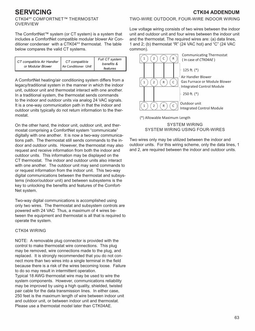
63
CTK04 ADDENDUM CTK04 ADDENDUMSERVICINGCTK04** COMFORTNET™ THERMOSTATOVERVIEW
The ComfortNet™ system (or CT system) is a system that includes a ComfortNet compatible modular blower Air Con-ditioner condenser with a CTK04** thermostat. The table below compares the valid CT systems.
CT compatible Air Handler or Modular Blower
CT compatibleAir Conditioner Unit
Full CT systembenefits & features
A ComfortNet heating/air conditioning system differs from a legacy/traditional system in the manner in which the indoor unit, outdoor unit and thermostat interact with one another. In a traditional system, the thermostat sends commands to the indoor and outdoor units via analog 24 VAC signals. It is a one-way communication path in that the indoor and outdoor units typically do not return information to the ther-mostat.
On the other hand, the indoor unit, outdoor unit, and ther-mostat comprising a ComfortNet system “communicate” digitally with one another. It is now a two-way communica-tions path. The thermostat still sends commands to the in-door and outdoor units. However, the thermostat may also request and receive information from both the indoor and outdoor units. This information may be displayed on the CT thermostat. The indoor and outdoor units also interact with one another. The outdoor unit may send commands to or request information from the indoor unit. This two-way digital communications between the thermostat and subsys-tems (indoor/outdoor unit) and between subsystems is the key to unlocking the benefits and features of the Comfort-Net system.
Two-way digital communications is accomplished using only two wires. The thermostat and subsystem controls are powered with 24 VAC Thus, a maximum of 4 wires be-tween the equipment and thermostat is all that is required to operate the system.
CTK04 WIRING
NOTE: A removable plug connector is provided with the control to make thermostat wire connections. This plug may be removed, wire connections made to the plug, and replaced. It is strongly recommended that you do not con-nect more than two wires into a single terminal in the field because there is a risk of the wires becoming loose. Failure to do so may result in intermittent operation.Typical 18 AWG thermostat wire may be used to wire the system components. However, communications reliability may be improved by using a high quality, shielded, twisted pair cable for the data transmission lines. In either case, 250 feet is the maximum length of wire between indoor unit and outdoor unit, or between indoor unit and thermostat. Please use a thermostat model later than CTK04AE.
TWO-WIRE OUTDOOR, FOUR-WIRE INDOOR WIRING
Low voltage wiring consists of two wires between the indoor unit and outdoor unit and four wires between the indoor unit and the thermostat. The required wires are: (a) data lines, 1 and 2; (b) thermostat “R” (24 VAC hot) and “C” (24 VAC common).
1 2 C R
1 2 R C
1 2 R C
Communica�ng Thermostat( In case of CTK04AE )
125 �. (*)
Air Handler BlowerGas Furnace or Module Blower Integrated Control Module
250 �. (*)
Outdoor unitIntegrated Control Module
(*) Allowable Maximum Length
SYSTEM WIRING SYSTEM WIRING USING FOUR-WIRES
Two wires only may be utilized between the indoor and outdoor units. For this wiring scheme, only the data lines, 1 and 2, are required between the indoor and outdoor units.
7-SEGMENT DISPLAY
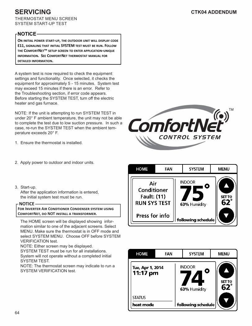
64
CTK04 ADDENDUMSERVICINGTHERMOSTAT MENU SCREENSYSTEM START-UP TEST
ON INITIAL POWER START-UP, THE OUTDOOR UNIT WILL DISPLAY CODE E11, SIGNALING THAT INITIAL SYSTEM TEST MUST BE RUN. FOLLOW THE COMFORTNET™ SETUP SCREEN TO ENTER APPLICATION-UNIQUE INFORMATION. SEE COMFORTNET THERMOSTAT MANUAL FOR DETAILED INFORMATION.
NOTICE
A system test is now required to check the equipmentsettings and functionality. Once selected, it checks theequipment for approximately 5 - 15 minutes. System testmay exceed 15 minutes if there is an error. Refer tothe Troubleshooting section, if error code appears.Before starting the SYSTEM TEST, turn off the electric heater and gas furnace.
NOTE: If the unit is attempting to run SYSTEM TEST in under 20° F ambient temperature, the unit may not be able to complete the test due to low suction pressure. In such a case, re-run the SYSTEM TEST when the ambient tem-perature exceeds 20° F.
1. Ensure the thermostat is installed.
2. Apply power to outdoor and indoor units.
3. Start-up. After the application information is entered, the initial system test must be run.
F�� I������� A�� C��������� C�������� ������ ����� C������N��, �� NOT ������� � �����������.
NOTICE
The HOME screen will be displayed showing infor-mation similar to one of the adjacent screens. Select MENU. Make sure the thermostat is in OFF mode and select SYSTEM MENU. Choose OFF before SYSTEM VERIFICATION test. NOTE: Either screen may be displayed. SYSTEM TEST must be run for all installations. System will not operate without a completed initial SYSTEM TEST. NOTE: The thermostat screen may indicate to run a SYSTEM VERIFICATION test.
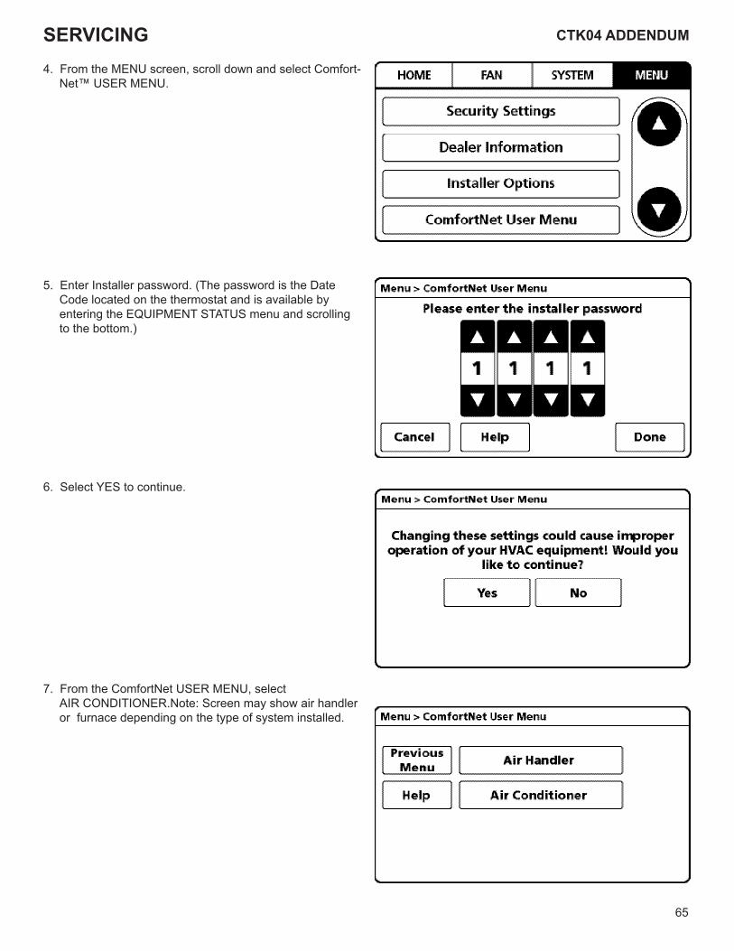
65
CTK04 ADDENDUM CTK04 ADDENDUMSERVICING4. From the MENU screen, scroll down and select Comfort-
Net™ USER MENU.
5. Enter Installer password. (The password is the Date Code located on the thermostat and is available by entering the EQUIPMENT STATUS menu and scrolling to the bottom.)
6. Select YES to continue.
7. From the ComfortNet USER MENU, select AIR CONDITIONER.Note: Screen may show air handler or furnace depending on the type of system installed.
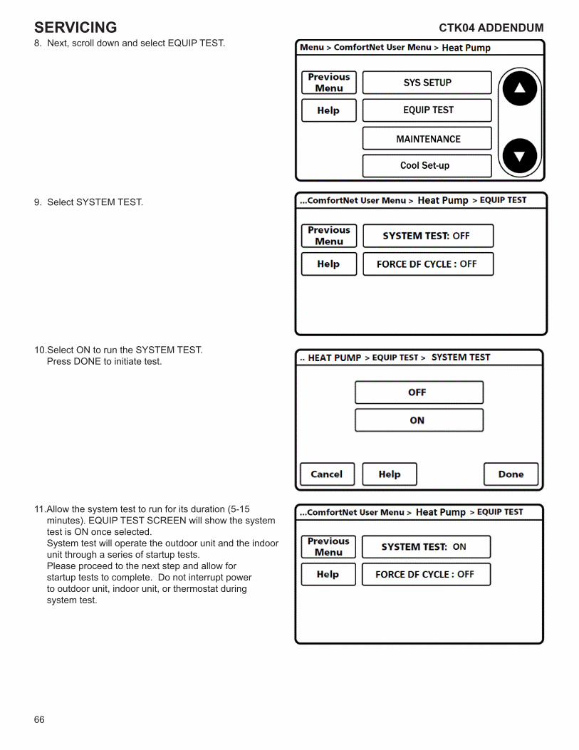
66
CTK04 ADDENDUMSERVICING8. Next, scroll down and select EQUIP TEST.
9. Select SYSTEM TEST.
10.Select ON to run the SYSTEM TEST. Press DONE to initiate test.
11.Allow the system test to run for its duration (5-15 minutes). EQUIP TEST SCREEN will show the system test is ON once selected. System test will operate the outdoor unit and the indoor unit through a series of startup tests. Please proceed to the next step and allow for startup tests to complete. Do not interrupt power to outdoor unit, indoor unit, or thermostat during system test.
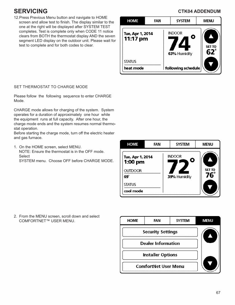
67
CTK04 ADDENDUM CTK04 ADDENDUMSERVICING12.Press Previous Menu button and navigate to HOME
screen and allow test to finish. The display similar to the one at the right will be displayed after SYSTEM TEST completes. Test is complete only when CODE 11 notice clears from BOTH the thermostat display AND the seven segment LED display on the outdoor unit. Please wait for test to complete and for both codes to clear.
SET THERMOSTAT TO CHARGE MODE
Please follow the following sequence to enter CHARGE Mode.
CHARGE mode allows for charging of the system. System operates for a duration of approximately one hour while the equipment runs at full capacity. After one hour, the charge mode ends and the system resumes normal thermo-stat operation.Before starting the charge mode, turn off the electric heater and gas furnace.
1. On the HOME screen, select MENU. NOTE: Ensure the thermostat is in the OFF mode. Select SYSTEM menu. Choose OFF before CHARGE MODE.
2. From the MENU screen, scroll down and select COMFORTNET™ USER MENU.
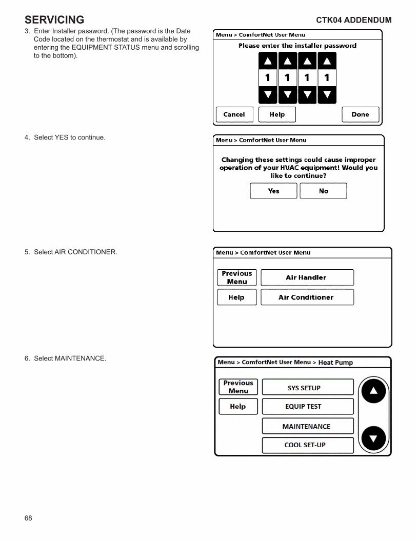
68
CTK04 ADDENDUMSERVICING3. Enter Installer password. (The password is the Date
Code located on the thermostat and is available by entering the EQUIPMENT STATUS menu and scrolling to the bottom).
4. Select YES to continue.
5. Select AIR CONDITIONER.
6. Select MAINTENANCE.
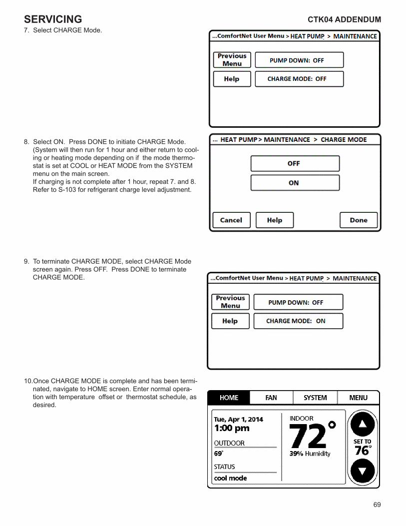
69
CTK04 ADDENDUM CTK04 ADDENDUMSERVICING7. Select CHARGE Mode.
8. Select ON. Press DONE to initiate CHARGE Mode. (System will then run for 1 hour and either return to cool-ing or heating mode depending on if the mode thermo-stat is set at COOL or HEAT MODE from the SYSTEM menu on the main screen. If charging is not complete after 1 hour, repeat 7. and 8. Refer to S-103 for refrigerant charge level adjustment.
9. To terminate CHARGE MODE, select CHARGE Mode screen again. Press OFF. Press DONE to terminate CHARGE MODE.
10.Once CHARGE MODE is complete and has been termi-nated, navigate to HOME screen. Enter normal opera-tion with temperature offset or thermostat schedule, as desired.
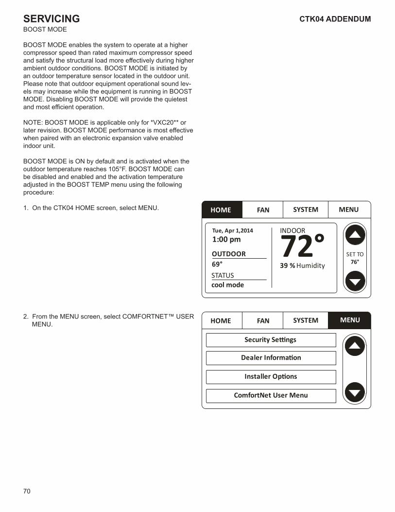
70
CTK04 ADDENDUMSERVICINGBOOST MODE
BOOST MODE enables the system to operate at a higher compressor speed than rated maximum compressor speed and satisfy the structural load more effectively during higher ambient outdoor conditions. BOOST MODE is initiated by an outdoor temperature sensor located in the outdoor unit. Please note that outdoor equipment operational sound lev-els may increase while the equipment is running in BOOST MODE. Disabling BOOST MODE will provide the quietest and most efficient operation.
NOTE: BOOST MODE is applicable only for *VXC20** or later revision. BOOST MODE performance is most effective when paired with an electronic expansion valve enabled indoor unit.
BOOST MODE is ON by default and is activated when the outdoor temperature reaches 105°F. BOOST MODE can be disabled and enabled and the activation temperature adjusted in the BOOST TEMP menu using the following procedure:
1. On the CTK04 HOME screen, select MENU.
2. From the MENU screen, select COMFORTNET™ USER MENU.
HOME FAN SYSTEM MENU
Tue, Apr 1,20141:00 pm
INDOOR
Humidity39 % 72°OUTDOOR
STATUScool mode
69°SET TO
76°
HOME FAN SYSTEM MENU
Security Se�ngs
Dealer Informa�on
Installer Op�ons
ComfortNet User Menu
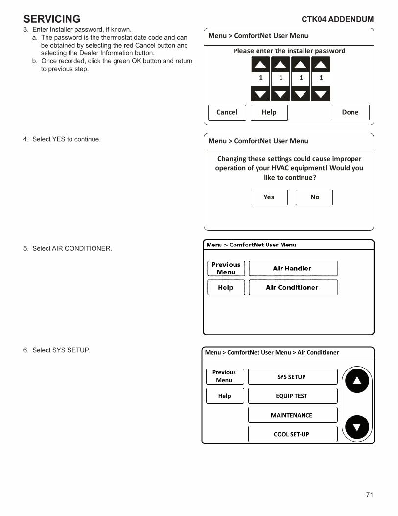
71
CTK04 ADDENDUM CTK04 ADDENDUMSERVICING3. Enter Installer password, if known.
a. The password is the thermostat date code and can be obtained by selecting the red Cancel button and selecting the Dealer Information button.
b. Once recorded, click the green OK button and return to previous step.
4. Select YES to continue.
5. Select AIR CONDITIONER.
6. Select SYS SETUP.
Menu > ComfortNet User Menu
Changing these se�ngs could cause improperopera�on of your HVAC equipment! Would you
like to con�nue?
Yes No
Menu > ComfortNet User Menu
Please enter the installer password
Cancel Help Done
1 1 1 1
Help EQUIP TEST
SYS SETUP
MAINTENANCE
COOL SET-UP
PreviousMenu
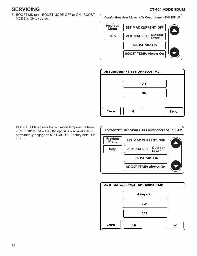
72
CTK04 ADDENDUMSERVICING7. BOOST MD turns BOOST MODE OFF or ON. BOOST
MODE is ON by default.
8. BOOST TEMP adjusts the activation temperature from 70°F to 105°F. “Always ON” option is also available to permanently engage BOOST MODE. Factory default is 105°F.
...ComfortNet User Menu > Air Condi oner > SYS SET-UP
Help
PreviousMenu
VERTICAL RISE:
BOOST MD: ON
BOOST TEMP: Always On
SET MAX CURRENT: OFF
OutdoorLower
...ComfortNet User Menu > Air Condi oner > SYS SET-UP
Help
PreviousMenu
VERTICAL RISE:
BOOST MD: ON
BOOST TEMP: Always On
SET MAX CURRENT: OFF
OutdoorLower
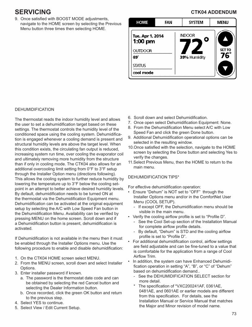
73
CTK04 ADDENDUM CTK04 ADDENDUMSERVICING9. Once satisfied with BOOST MODE adjustments,
navigate to the HOME screen by selecting the Previous Menu button three times then selecting HOME.
DEHUMIDIFICATION
The thermostat reads the indoor humidity level and allows the user to set a dehumidification target based on these settings. The thermostat controls the humidity level of the conditioned space using the cooling system. Dehumidifica-tion is engaged whenever a cooling demand is present and structural humidity levels are above the target level. When this condition exists, the circulating fan output is reduced, increasing system run time, over cooling the evaporator coil and ultimately removing more humidity from the structure than if only in cooling mode. The CTK04 also allows for an additional overcooling limit setting from 0°F to 3°F setup through the Installer Option menu (directions following). This allows the cooling system to further reduce humidity by lowering the temperature up to 3°F below the cooling set-point in an attempt to better achieve desired humidity levels.By default, dehumidification needs to be turned ON at the thermostat via the Dehumidification Equipment menu. Dehumidification can be activated at the original equipment setup by selecting the A/C with Low Speed Fan button in the Dehumidification Menu. Availability can be verified by pressing MENU on the home screen. Scroll down and if a Dehumidification button is present, dehumidification is activated.
If Dehumidification is not available in the menu then it must be enabled through the Installer Options menu. Use the following procedure to enable and disable dehumidification:
1. On the CTK04 HOME screen select MENU.2. From the MENU screen, scroll down and select Installer
Options.3. Enter installer password if known.
a. The password is the thermostat date code and can be obtained by selecting the red Cancel button and selecting the Dealer Information button.
b. Once recorded, click the green OK button and return to the previous step.
4. Select YES to continue.5. Select View / Edit Current Setup.
6. Scroll down and select Dehumidification.7. Once open select Dehumidification Equipment: None.8. From the Dehumidification Menu select A/C with Low
Speed Fan and click the green Done button.9. Additional Dehumidification operational options can be
selected in the resulting window.10.Once satisfied with the selection, navigate to the HOME
screen by selecting the Done button and selecting Yes to verify the changes.
11.Select Previous Menu, then the HOME to return to the main menu.
DEHUMIDIFICATION TIPS*
For effective dehumidification operation:• Ensure “Dehum” is NOT set to “OFF” through the
Installer Options menu and/or in the ComfortNet User Menu (COOL SETUP).- If except OFF, the Dehumidification menu should be
visible in the main menu.• Verify the cooling airflow profile is set to “Profile D”.
- See the Cool Set-up section of the Installation Manual for complete airflow profile details.
- By default, “Dehum” is STD and the cooling airflow profile is set to “Profile D”.
• For additional dehumidification control, airflow settings are field adjustable and can be fine-tuned to a value that is comfortable for the application from a range of Cool Airflow Trim.
• In addition, the system can have Enhanced Dehumidi-fication operation in setting “A”, “B”, or “C” of “Dehum” based on dehumidification demand.. - See the DEHUMIDIFICATION SELECT section for
more detail.* The specification of *VXC200241AF, 0361AE,
0481AE, and 0601AE or earlier models are different from this specification. For details, see the Installation Manual or Service Manual that matches the Major and Minor revision of model name.
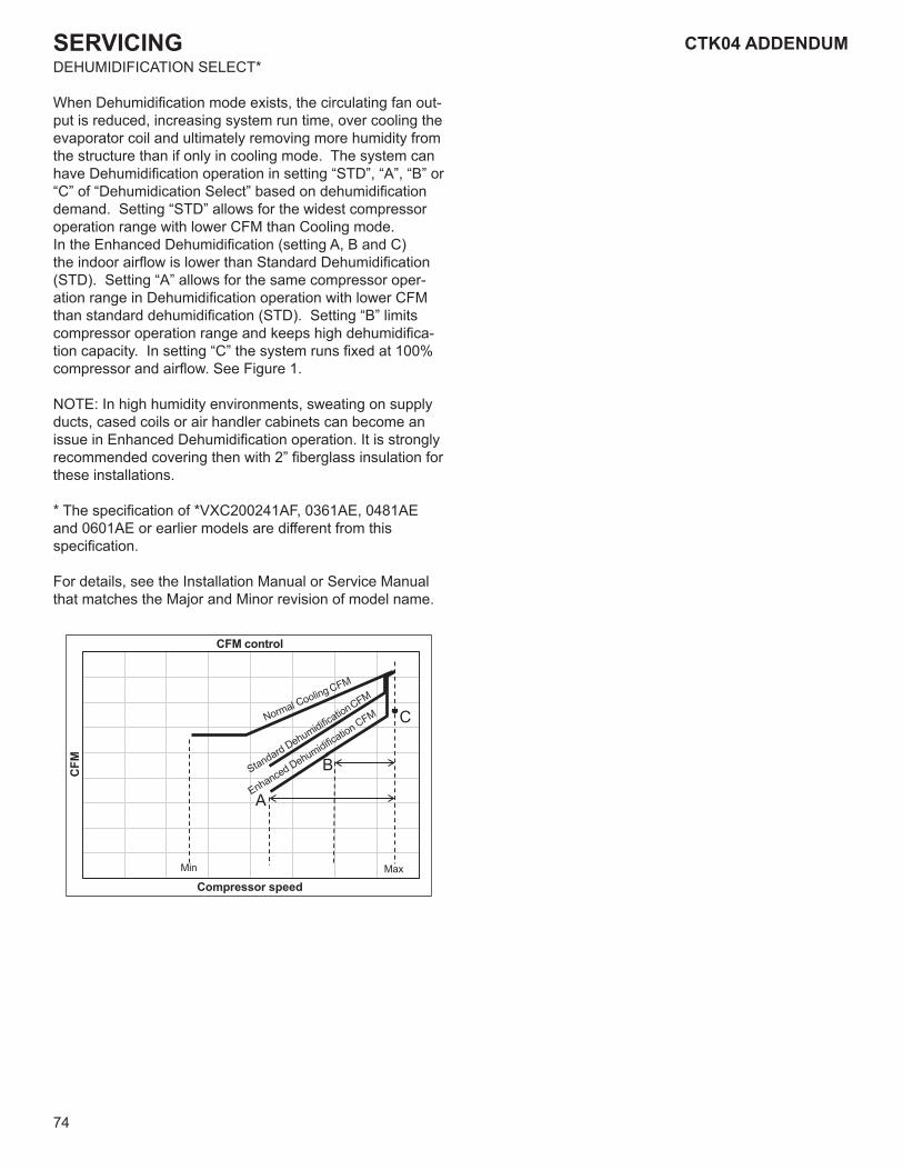
74
CTK04 ADDENDUMSERVICINGDEHUMIDIFICATION SELECT*
When Dehumidification mode exists, the circulating fan out-put is reduced, increasing system run time, over cooling the evaporator coil and ultimately removing more humidity from the structure than if only in cooling mode. The system can have Dehumidification operation in setting “STD”, “A”, “B” or “C” of “Dehumidication Select” based on dehumidification demand. Setting “STD” allows for the widest compressor operation range with lower CFM than Cooling mode.In the Enhanced Dehumidification (setting A, B and C) the indoor airflow is lower than Standard Dehumidification (STD). Setting “A” allows for the same compressor oper-ation range in Dehumidification operation with lower CFM than standard dehumidification (STD). Setting “B” limits compressor operation range and keeps high dehumidifica-tion capacity. In setting “C” the system runs fixed at 100% compressor and airflow. See Figure 1.
NOTE: In high humidity environments, sweating on supply ducts, cased coils or air handler cabinets can become an issue in Enhanced Dehumidification operation. It is strongly recommended covering then with 2” fiberglass insulation for these installations.
* The specification of *VXC200241AF, 0361AE, 0481AE and 0601AE or earlier models are different from this specification.
For details, see the Installation Manual or Service Manual that matches the Major and Minor revision of model name.
CFM
Min
Compressor speedMax
C
B
A
CFM control
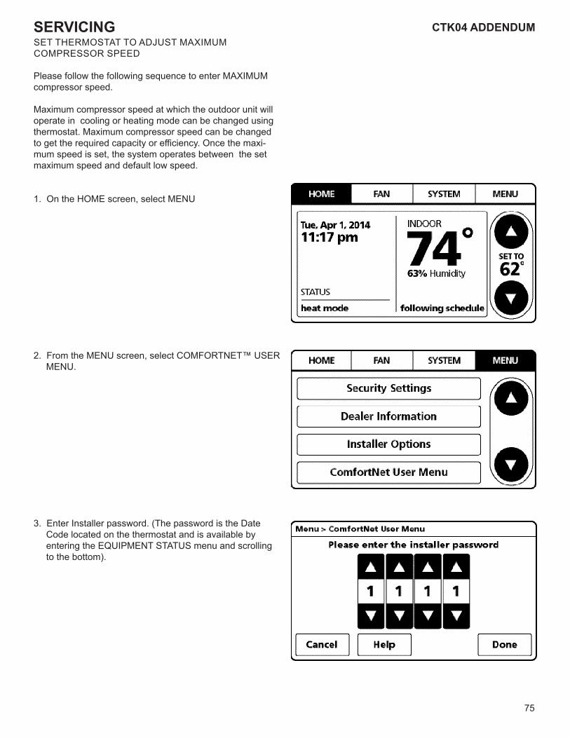
75
CTK04 ADDENDUM CTK04 ADDENDUMSERVICINGSET THERMOSTAT TO ADJUST MAXIMUM COMPRESSOR SPEED
Please follow the following sequence to enter MAXIMUMcompressor speed.
Maximum compressor speed at which the outdoor unit will operate in cooling or heating mode can be changed using thermostat. Maximum compressor speed can be changed to get the required capacity or efficiency. Once the maxi-mum speed is set, the system operates between the set maximum speed and default low speed.
1. On the HOME screen, select MENU
2. From the MENU screen, select COMFORTNET™ USER MENU.
3. Enter Installer password. (The password is the Date Code located on the thermostat and is available by entering the EQUIPMENT STATUS menu and scrolling to the bottom).
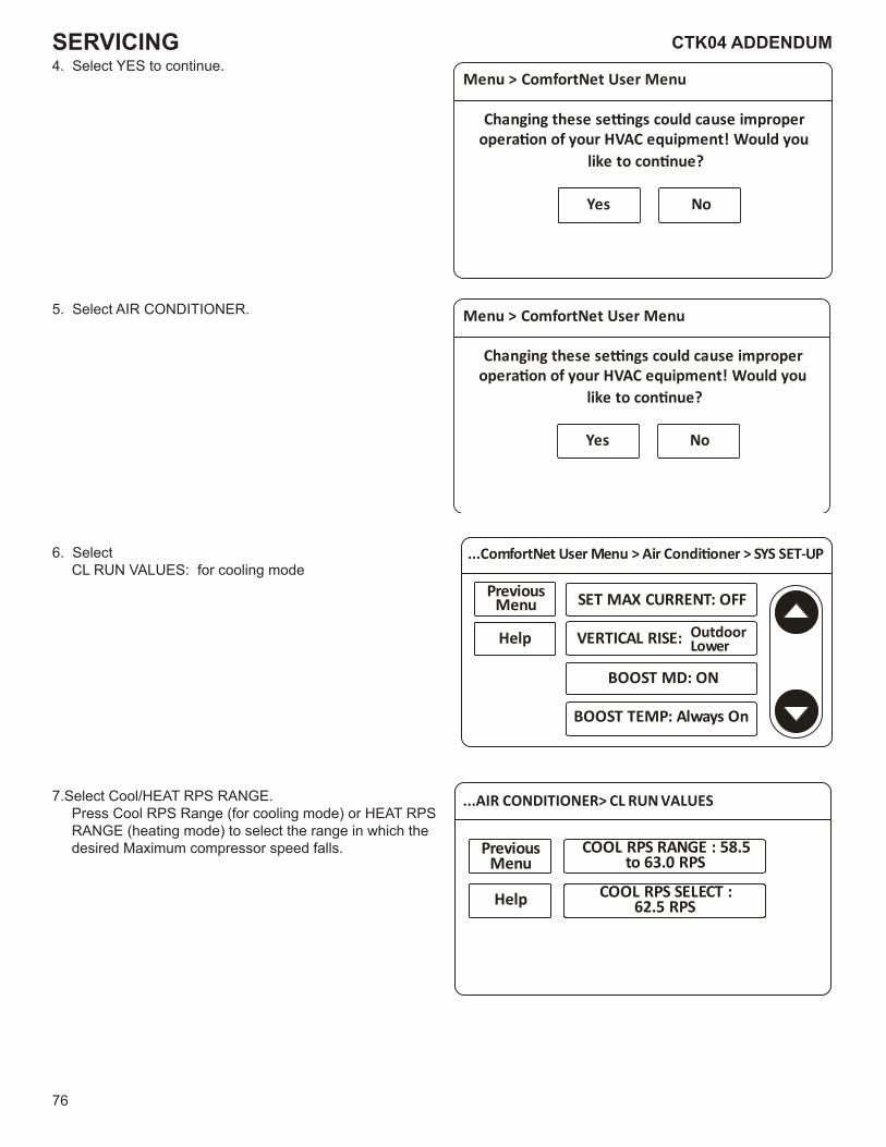
76
CTK04 ADDENDUMSERVICING4. Select YES to continue.
5. Select AIR CONDITIONER.
6. Select CL RUN VALUES: for cooling mode
7.Select Cool/HEAT RPS RANGE. Press Cool RPS Range (for cooling mode) or HEAT RPS RANGE (heating mode) to select the range in which the desired Maximum compressor speed falls.
Menu > ComfortNet User Menu
Changing these se�ngs could cause improperopera�on of your HVAC equipment! Would you
like to con�nue?
Yes No
Menu > ComfortNet User Menu
Changing these se�ngs could cause improperopera�on of your HVAC equipment! Would you
like to con�nue?
Yes No
...ComfortNet User Menu > Air Condi oner > SYS SET-UP
Help
PreviousMenu
VERTICAL RISE:
BOOST MD: ON
BOOST TEMP: Always On
SET MAX CURRENT: OFF
OutdoorLower
...AIR CONDITIONER> CL RUN VALUES
Help
PreviousMenu
COOL RPS RANGE : 58.5 to 63.0 RPS
COOL RPS SELECT : 62.5 RPS
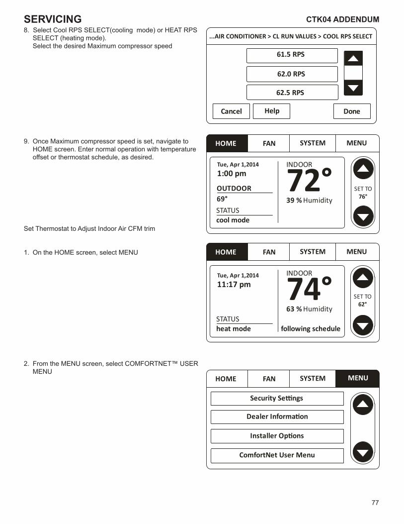
77
CTK04 ADDENDUM CTK04 ADDENDUMSERVICING8. Select Cool RPS SELECT(cooling mode) or HEAT RPS
SELECT (heating mode). Select the desired Maximum compressor speed
9. Once Maximum compressor speed is set, navigate to HOME screen. Enter normal operation with temperature
offset or thermostat schedule, as desired.
Set Thermostat to Adjust Indoor Air CFM trim
1. On the HOME screen, select MENU
2. From the MENU screen, select COMFORTNET™ USER MENU
HOME FAN SYSTEM MENU
Security Se�ngs
Dealer Informa�on
Installer Op�ons
ComfortNet User Menu
HOME FAN SYSTEM MENU
Tue, Apr 1,201411:17 pm
INDOOR
Humidity63 % 74°
following scheduleSTATUSheat mode
SET TO62°
HOME FAN SYSTEM MENU
Tue, Apr 1,20141:00 pm
INDOOR
Humidity39 % 72°OUTDOOR
STATUScool mode
69°SET TO
76°
...AIR CONDITIONER > CL RUN VALUES > COOL RPS SELECT
Help
61.5 RPS
62.0 RPS
Cancel Done
62.5 RPS
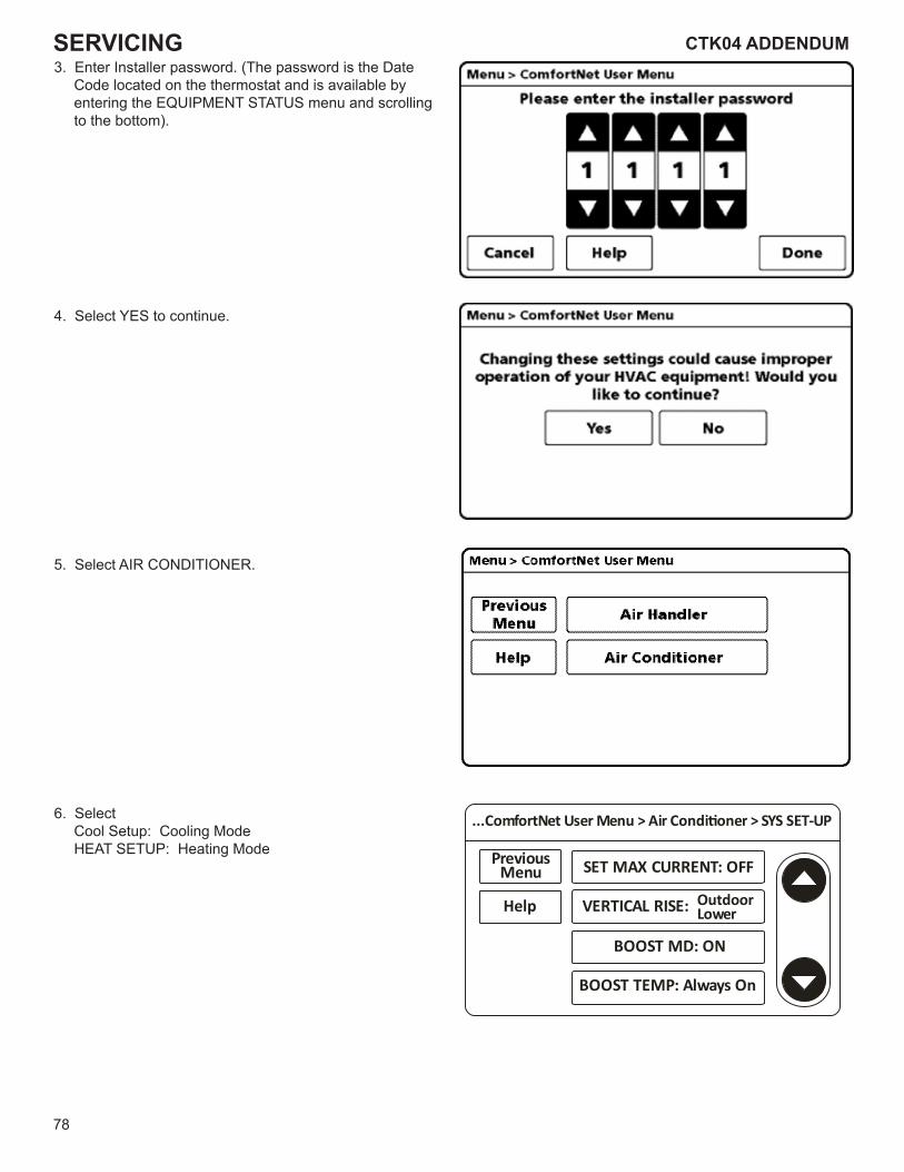
78
CTK04 ADDENDUMSERVICING3. Enter Installer password. (The password is the Date
Code located on the thermostat and is available by entering the EQUIPMENT STATUS menu and scrolling to the bottom).
4. Select YES to continue.
5. Select AIR CONDITIONER.
6. Select Cool Setup: Cooling Mode HEAT SETUP: Heating Mode
...ComfortNet User Menu > Air Condi oner > SYS SET-UP
Help
PreviousMenu
VERTICAL RISE:
BOOST MD: ON
BOOST TEMP: Always On
SET MAX CURRENT: OFF
OutdoorLower
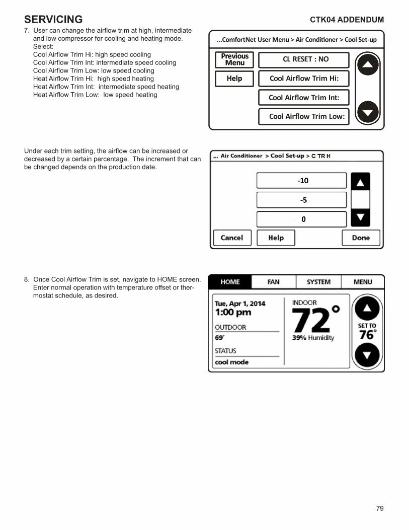
79
CTK04 ADDENDUM CTK04 ADDENDUMSERVICING7. User can change the airflow trim at high, intermediate
and low compressor for cooling and heating mode.Select: Cool Airflow Trim Hi: high speed cooling Cool Airflow Trim Int: intermediate speed cooling Cool Airflow Trim Low: low speed cooling Heat Airflow Trim Hi: high speed heating Heat Airflow Trim Int: intermediate speed heating Heat Airflow Trim Low: low speed heating
Under each trim setting, the airflow can be increased or decreased by a certain percentage. The increment that can be changed depends on the production date.
8. Once Cool Airflow Trim is set, navigate to HOME screen. Enter normal operation with temperature offset or ther-mostat schedule, as desired.
...ComfortNet User Menu > Air Condi�oner > Cool Set-up
Help
PreviousMenu CL RESET : NO
Cool Airflow Trim Hi:Help
PreviousMenu
Cool Airflow Trim Int:
Cool Airflow Trim Low:
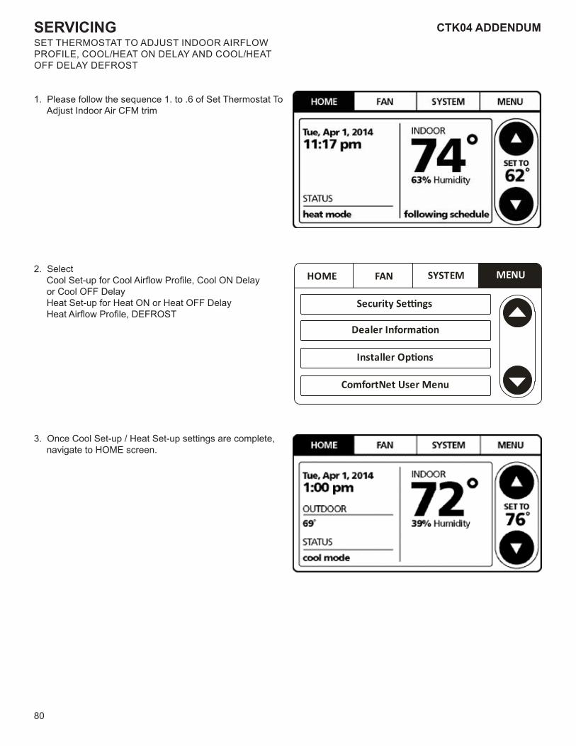
80
CTK04 ADDENDUMSERVICINGSET THERMOSTAT TO ADJUST INDOOR AIRFLOWPROFILE, COOL/HEAT ON DELAY AND COOL/HEAT OFF DELAY DEFROST
1. Please follow the sequence 1. to .6 of Set Thermostat To Adjust Indoor Air CFM trim
2. Select Cool Set-up for Cool Airflow Profile, Cool ON Delay
or Cool OFF Delay Heat Set-up for Heat ON or Heat OFF Delay Heat Airflow Profile, DEFROST
3. Once Cool Set-up / Heat Set-up settings are complete, navigate to HOME screen.
HOME FAN SYSTEM MENU
Security Se�ngs
Dealer Informa�on
Installer Op�ons
ComfortNet User Menu
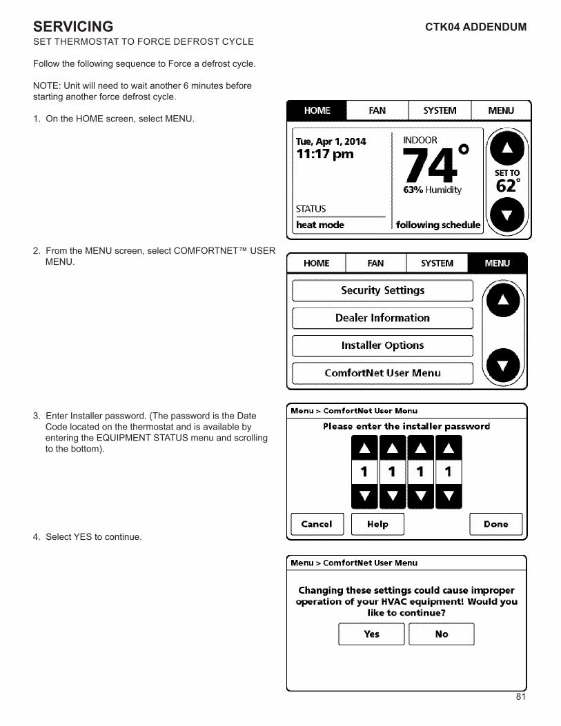
81
CTK04 ADDENDUM CTK04 ADDENDUMSERVICINGSET THERMOSTAT TO FORCE DEFROST CYCLE
Follow the following sequence to Force a defrost cycle.
NOTE: Unit will need to wait another 6 minutes before starting another force defrost cycle.
1. On the HOME screen, select MENU.
2. From the MENU screen, select COMFORTNET™ USER MENU.
3. Enter Installer password. (The password is the Date Code located on the thermostat and is available by entering the EQUIPMENT STATUS menu and scrolling to the bottom).
4. Select YES to continue.
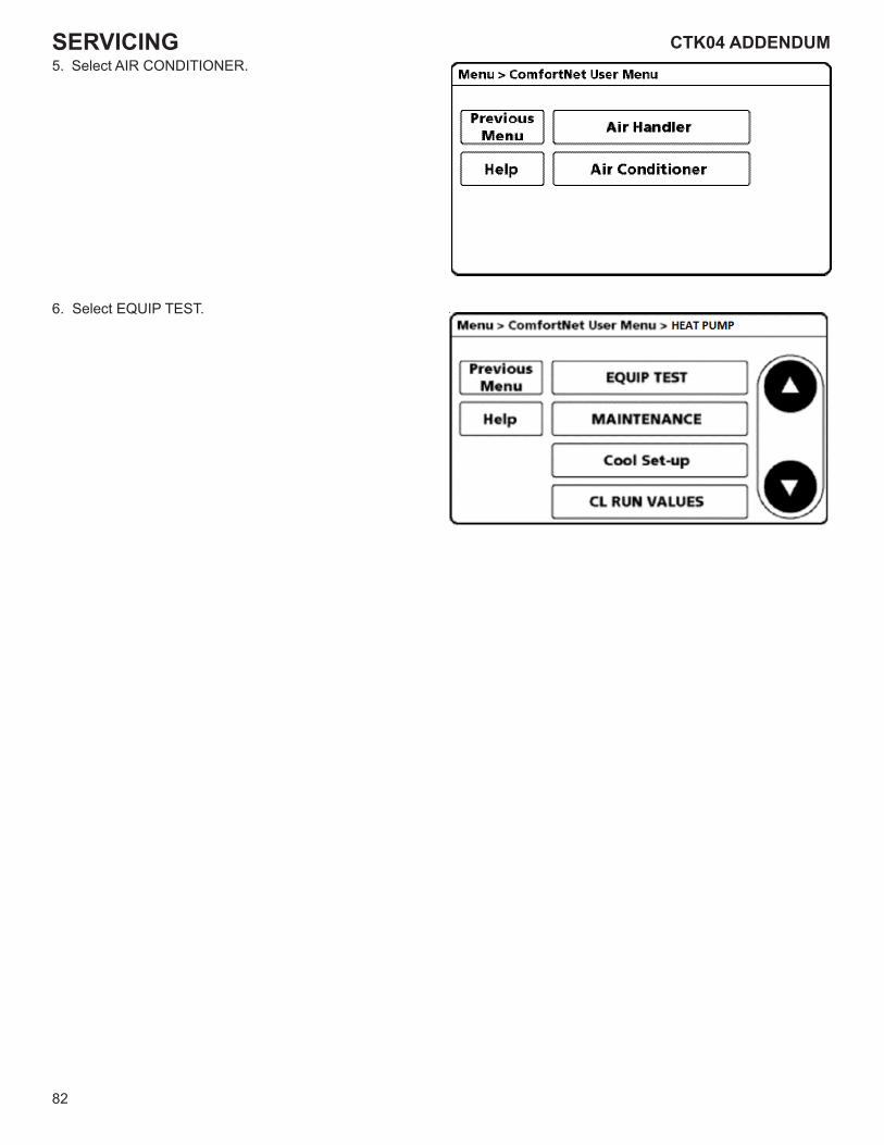
82
CTK04 ADDENDUMSERVICING5. Select AIR CONDITIONER.
6. Select EQUIP TEST.
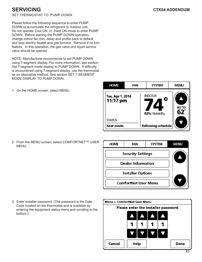
83
CTK04 ADDENDUM CTK04 ADDENDUMSERVICINGSET THERMOSTAT TO PUMP DOWN
Please follow the following sequence to enter PUMP DOWN to accumulate the refrigerant to outdoor unit.Do not operate Cool ON or Heat ON mode to enter PUMP DOWN. Before starting the PUMP DOWN operation, change indoor fan trim, delay and profile back to default and stop electric heater and gas furnace. Remove if no trim feature. In this operation, the gas valve and liquid service valve should be opened.
NOTE: Manufacturer recommends to set PUMP DOWN using 7-segment display. For more information, see section Set 7-segment mode display to PUMP DOWN. If difficulty is encountered using 7-segment display, use the thermostat as an alternative method. See section SET 7-SEGMENT MODE DISPLAY TO PUMP DOWN.
1. On the HOME screen, select MENU.
2. From the MENU screen, select COMFORTNET™ USER MENU.
3. Enter installer password. (The password is the Date Code located on the thermostat and is available by entering the equipment status menu and scrolling to the bottom.)
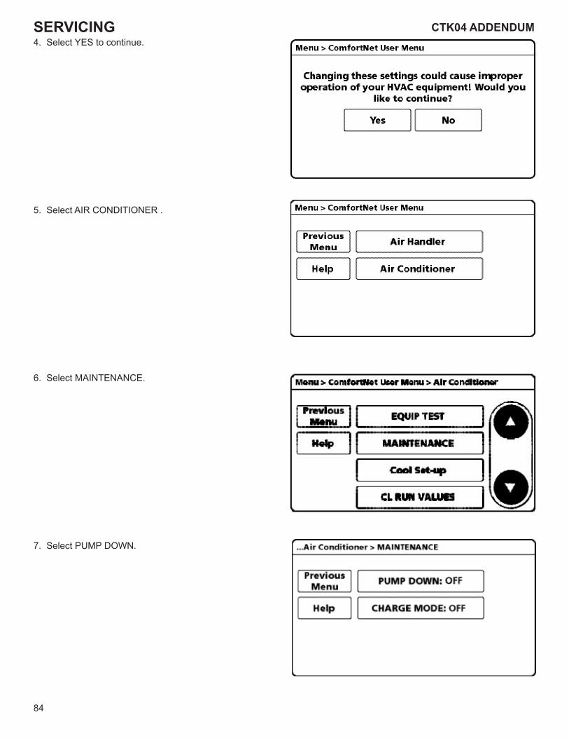
84
CTK04 ADDENDUMSERVICING4. Select YES to continue.
5. Select AIR CONDITIONER .
6. Select MAINTENANCE.
7. Select PUMP DOWN.
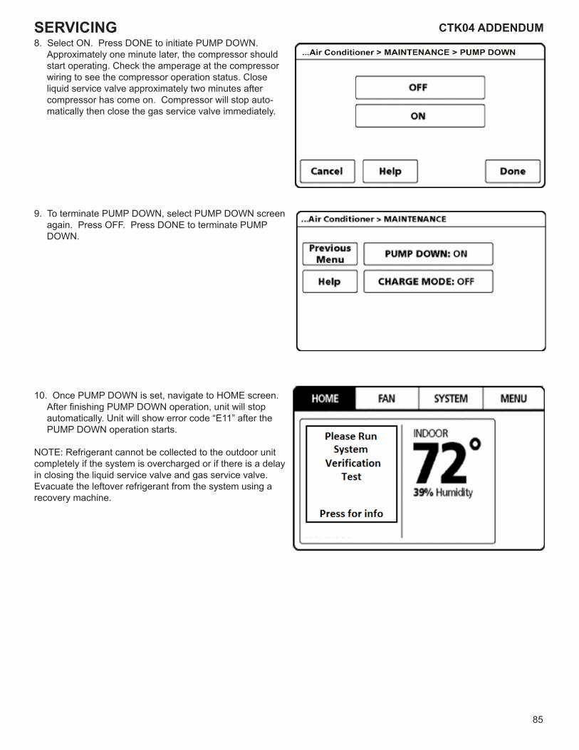
85
CTK04 ADDENDUM CTK04 ADDENDUMSERVICING8. Select ON. Press DONE to initiate PUMP DOWN.
Approximately one minute later, the compressor should start operating. Check the amperage at the compressor wiring to see the compressor operation status. Close liquid service valve approximately two minutes after compressor has come on. Compressor will stop auto-matically then close the gas service valve immediately.
9. To terminate PUMP DOWN, select PUMP DOWN screen again. Press OFF. Press DONE to terminate PUMP DOWN.
10. Once PUMP DOWN is set, navigate to HOME screen. After finishing PUMP DOWN operation, unit will stop automatically. Unit will show error code “E11” after the PUMP DOWN operation starts.
NOTE: Refrigerant cannot be collected to the outdoor unit completely if the system is overcharged or if there is a delay in closing the liquid service valve and gas service valve. Evacuate the leftover refrigerant from the system using a recovery machine.
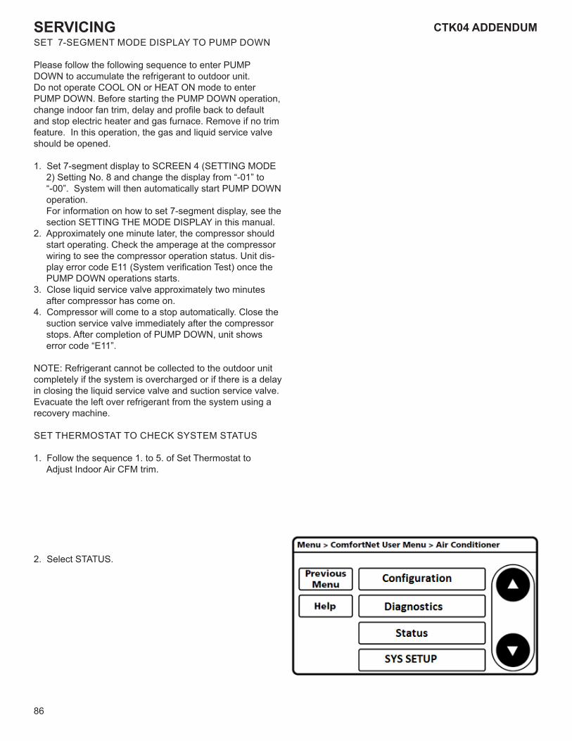
86
CTK04 ADDENDUMSERVICINGSET 7-SEGMENT MODE DISPLAY TO PUMP DOWN
Please follow the following sequence to enter PUMP DOWN to accumulate the refrigerant to outdoor unit.Do not operate COOL ON or HEAT ON mode to enter PUMP DOWN. Before starting the PUMP DOWN operation, change indoor fan trim, delay and profile back to default and stop electric heater and gas furnace. Remove if no trim feature. In this operation, the gas and liquid service valve should be opened.
1. Set 7-segment display to SCREEN 4 (SETTING MODE 2) Setting No. 8 and change the display from “-01” to “-00”. System will then automatically start PUMP DOWN operation. For information on how to set 7-segment display, see the section SETTING THE MODE DISPLAY in this manual.
2. Approximately one minute later, the compressor should start operating. Check the amperage at the compressor wiring to see the compressor operation status. Unit dis-play error code E11 (System verification Test) once the PUMP DOWN operations starts.
3. Close liquid service valve approximately two minutes after compressor has come on.
4. Compressor will come to a stop automatically. Close the suction service valve immediately after the compressor stops. After completion of PUMP DOWN, unit shows error code “E11”.
NOTE: Refrigerant cannot be collected to the outdoor unit completely if the system is overcharged or if there is a delay in closing the liquid service valve and suction service valve. Evacuate the left over refrigerant from the system using a recovery machine.
SET THERMOSTAT TO CHECK SYSTEM STATUS
1. Follow the sequence 1. to 5. of Set Thermostat to Adjust Indoor Air CFM trim.
2. Select STATUS.
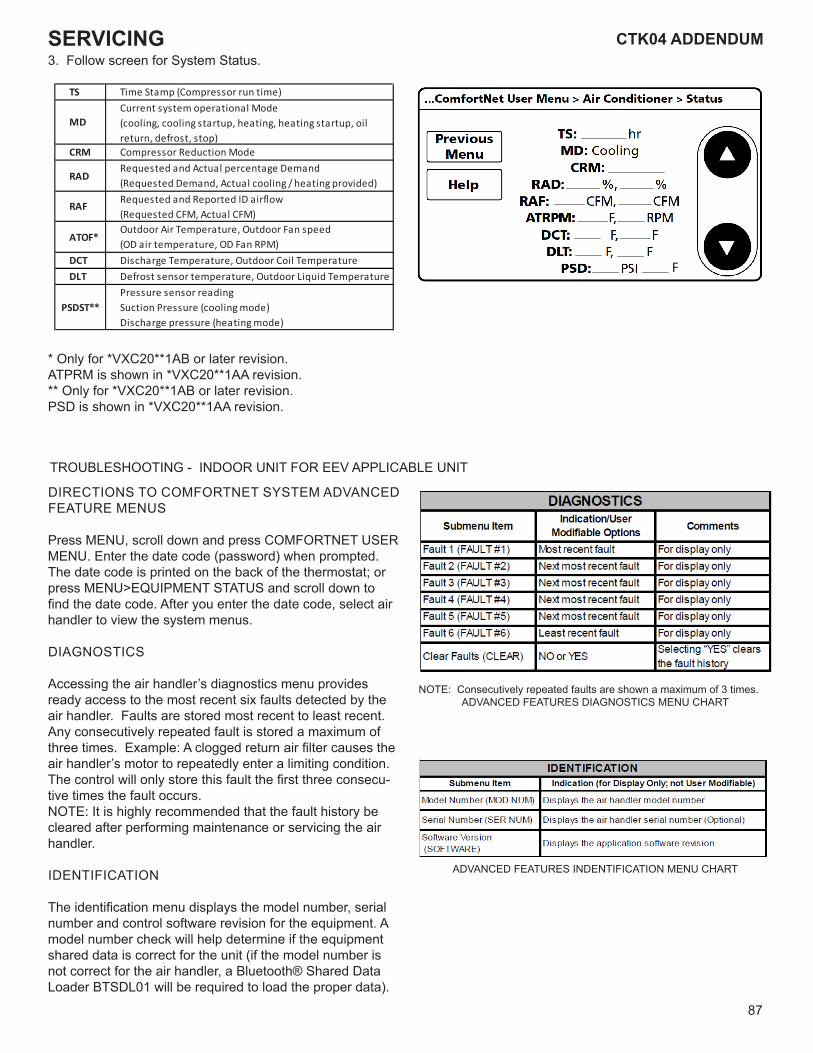
87
CTK04 ADDENDUM CTK04 ADDENDUMSERVICING3. Follow screen for System Status.
TS Time Stamp (Compressor run time)
MDCurrent system operational Mode(cooling, cooling startup, heating, heating startup, oil return, defrost, stop)
CRM Compressor Reduction Mode
RADRequested and Actual percentage Demand(Requested Demand, Actual cooling / heating provided)
RAFRequested and Reported ID airflow(Requested CFM, Actual CFM)
ATOF*Outdoor Air Temperature, Outdoor Fan speed(OD air temperature, OD Fan RPM)
DCT Discharge Temperature, Outdoor Coil TemperatureDLT Defrost sensor temperature, Outdoor Liquid Temperature
PSDST**Pressure sensor reading Suction Pressure (cooling mode)Discharge pressure (heating mode)
* Only for *VXC20**1AB or later revision.ATPRM is shown in *VXC20**1AA revision.** Only for *VXC20**1AB or later revision.PSD is shown in *VXC20**1AA revision.
TROUBLESHOOTING - INDOOR UNIT FOR EEV APPLICABLE UNIT
DIRECTIONS TO COMFORTNET SYSTEM ADVANCED FEATURE MENUS
Press MENU, scroll down and press COMFORTNET USER MENU. Enter the date code (password) when prompted. The date code is printed on the back of the thermostat; or press MENU>EQUIPMENT STATUS and scroll down to find the date code. After you enter the date code, select air handler to view the system menus.
DIAGNOSTICS
Accessing the air handler’s diagnostics menu provides ready access to the most recent six faults detected by the air handler. Faults are stored most recent to least recent. Any consecutively repeated fault is stored a maximum of three times. Example: A clogged return air filter causes the air handler’s motor to repeatedly enter a limiting condition. The control will only store this fault the first three consecu-tive times the fault occurs. NOTE: It is highly recommended that the fault history be cleared after performing maintenance or servicing the air handler.
IDENTIFICATION
The identification menu displays the model number, serial number and control software revision for the equipment. A model number check will help determine if the equipment shared data is correct for the unit (if the model number is not correct for the air handler, a Bluetooth® Shared Data Loader BTSDL01 will be required to load the proper data).
NOTE: Consecutively repeated faults are shown a maximum of 3 times.ADVANCED FEATURES DIAGNOSTICS MENU CHART
ADVANCED FEATURES INDENTIFICATION MENU CHART
F
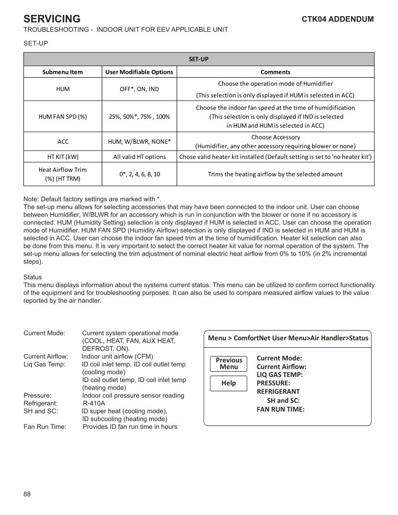
88
CTK04 ADDENDUMSERVICING
Submenu Item User Modifiable Options Comments
Choose the operation mode of Humidifier
(This selection is only displayed if HUM is selected in ACC)
HUM FAN SPD (%) 25%, 50%*, 75% , 100%Choose the indoor fan speed at the time of humidification
(This selection is only displayed if IND is selected in HUM and HUM is selected in ACC)
ACC HUM, W/BLWR, NONE*Choose Accessory
(Humidifier, any other accessory requiring blower or none)
HT KIT (kW) All valid HT options Chose valid heater kit installed (Default setting is set to 'no heater kit')
Heat Airflow Trim(%) (HT TRM)
0*, 2, 4, 6, 8, 10 Trims the heating airflow by the selected amount
SET-UP
HUM OFF*, ON, IND
Note: Default factory settings are marked with *.The set-up menu allows for selecting accessories that may have been connected to the indoor unit. User can choose between Humidifier, W/BLWR for an accessory which is run in conjunction with the blower or none if no accessory is connected. HUM (Humidity Setting) selection is only displayed if HUM is selected in ACC. User can choose the operation mode of Humidifier. HUM FAN SPD (Humidity Airflow) selection is only displayed if IND is selected in HUM and HUM is selected in ACC. User can choose the indoor fan speed trim at the time of humidification. Heater kit selection can also be done from this menu. It is very important to select the correct heater kit value for normal operation of the system. The set-up menu allows for selecting the trim adjustment of nominal electric heat airflow from 0% to 10% (in 2% incremental steps).
StatusThis menu displays information about the systems current status. This menu can be utilized to confirm correct functionality of the equipment and for troubleshooting purposes. It can also be used to compare measured airflow values to the value reported by the air handler.
Current Mode: Current system operational mode (COOL, HEAT, FAN, AUX HEAT, DEFROST, ON).
Current Airflow: Indoor unit airflow (CFM)Liq Gas Temp: ID coil inlet temp, ID coil outlet temp
(cooling mode) ID coil outlet temp, ID coil inlet temp (heating mode)
Pressure: Indoor coil pressure sensor readingRefrigerant: R-410ASH and SC: ID super heat (cooling mode),
ID subcooling (heating mode)Fan Run Time: Provides ID fan run time in hours
TROUBLESHOOTING - INDOOR UNIT FOR EEV APPLICABLE UNIT
SET-UP
Menu > ComfortNet User Menu>Air Handler>Status
Help
PreviousMenu
Current Mode:Current Airflow:LIQ GAS TEMP:PRESSURE:REFRIGERANT
SH and SC:FAN RUN TIME:

89
CTK04 ADDENDUM CTK04 ADDENDUMSERVICINGAIR CONDITIONER ADVANCED FEATURE MENU
SUBMENU ITEMINDICATION/USERMODIFIABLE OPTIONS COMMENTS
.yrotsih tluaf eht sraelc "SEY" gnitceleSSEY ro ONstluaF raelC
tluaf PH tnecer tsoM1 tluaF
tluaf PH tnecer tsom dn22 tluaF
tluaf PH tnecer tsom dr33 tluaF
tluaf PH tnecer tsom ht44 tluaF
tluaf PH tnecer tsom ht55 tluaF
tluaf PH tnecer tsom ht66 tluaF
STNEMMOCMETI UNEMBUS
Time Stamp (TS)
Mode (MD)
Compressor Reduc�on Mode (CRM)
Requested and Actual % Demand (RAD)
Requested and Reported ID CFM (RAF)
Outdoor Air Temperature and Outdoor Fan RPM (ATOF*)Discharge Temperature and Outdoor Coil Temperature (DCT)Defrost sensor and Outdoor Liquid Temperature (DLT)
Pressure Sensor (PSDST**)
DIAGNOSTICS
STATUS
Provides compressor run �me in hours.
Current system opera�on mode (COOLING, COOLING STARTUP, HEATING, HEATING STARTUP, DEFROST, OIL RETURN, STOP).Displays ON or OFF status. ON indicates that the reduc�on mode is opera�ng and the compressor is running at a lower speed than the cooling load would normally require.Displays a 0-100% value, based on a ra�o of the requested cooling demand to what the system is actually providing.
Compares the requested indoor airflow to what the indoor equipment has reported.
Displays the outdoor air temperature as well as the outdoor fan speed (RPM).
Displays the discharge temperature and outdoor coil temperature sensor readings.
Displays the defrost temperature sensor and outdoor liquid temperature sensor reading.
Displays the pressure sensor reading which is taken slightly upstream of the suc�on accumulator.
* Only for *VZC20** or later revision. ATPRM is shown in *VZC20** revision.
** Only for *VZC20** or later revision. PSD is shown in *VZC20** revision.
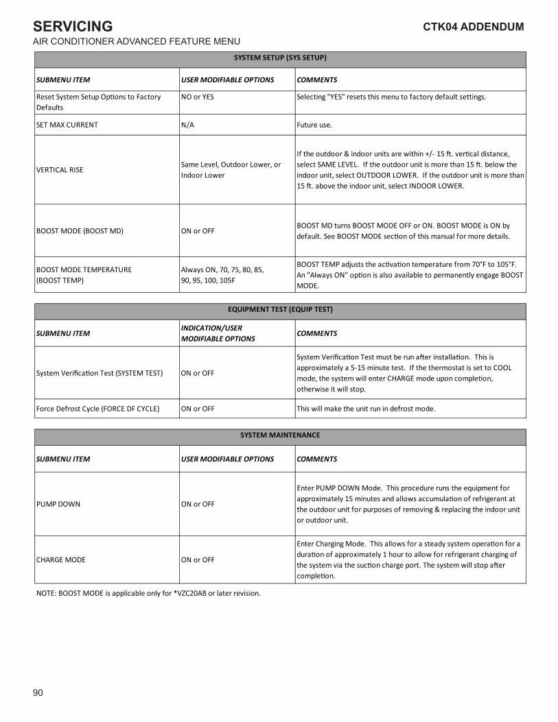
90
CTK04 ADDENDUMSERVICINGAIR CONDITIONER ADVANCED FEATURE MENU
STNEMMOCSNOITPO ELBAIFIDOM RESUMETI UNEMBUS
Reset System Setup Op�ons to Factory Defaults
.sgnittes tluafed yrotcaf ot unem siht steser "SEY" gnitceleSSEY ro ON
.esu erutuFA/NTNERRUC XAM TES
VERTICAL RISESame Level, Outdoor Lower, or Indoor Lower
If the outdoor & indoor units are within +/- 15 �. ver�cal distance, select SAME LEVEL. If the outdoor unit is more than 15 �. below the indoor unit, select OUTDOOR LOWER. If the outdoor unit is more than 15 �. above the indoor unit, select INDOOR LOWER.
BOOST MODE (BOOST MD) ON or OFFBOOST MD turns BOOST MODE OFF or ON. BOOST MODE is ON by default. See BOOST MODE sec�on of this manual for more details.
BOOST MODE TEMPERATURE(BOOST TEMP)
Always ON, 70, 75, 80, 85,90, 95, 100, 105F
BOOST TEMP adjusts the ac�va�on temperature from 70°F to 105°F. An "Always ON" op�on is also available to permanently engage BOOST MODE.
SUBMENU ITEMINDICATION/USERMODIFIABLE OPTIONS
COMMENTS
System Verifica�on Test (SYSTEM TEST) ON or OFF
System Verifica�on Test must be run a�er installa�on. This is approximately a 5-15 minute test. If the thermostat is set to COOL mode, the system will enter CHARGE mode upon comple�on, otherwise it will stop.
.edom tsorfed ni nur tinu eht ekam lliw sihTFFO ro NO)ELCYC FD ECROF( elcyC tsorfeD ecroF
STNEMMOCSNOITPO ELBAIFIDOM RESUMETI UNEMBUS
FFO ro NONWOD PMUP
Enter PUMP DOWN Mode. This procedure runs the equipment for approximately 15 minutes and allows accumula�on of refrigerant at the outdoor unit for purposes of removing & replacing the indoor unit or outdoor unit.
FFO ro NOEDOM EGRAHC
Enter Charging Mode. This allows for a steady system opera�on for a dura�on of approximately 1 hour to allow for refrigerant charging of the system via the suc�on charge port. The system will stop a�er comple�on.
NOTE: BOOST MODE is applicable only for *VZC20AB or later revision.
SYSTEM SETUP (SYS SETUP)
EQUIPMENT TEST (EQUIP TEST)
SYSTEM MAINTENANCE
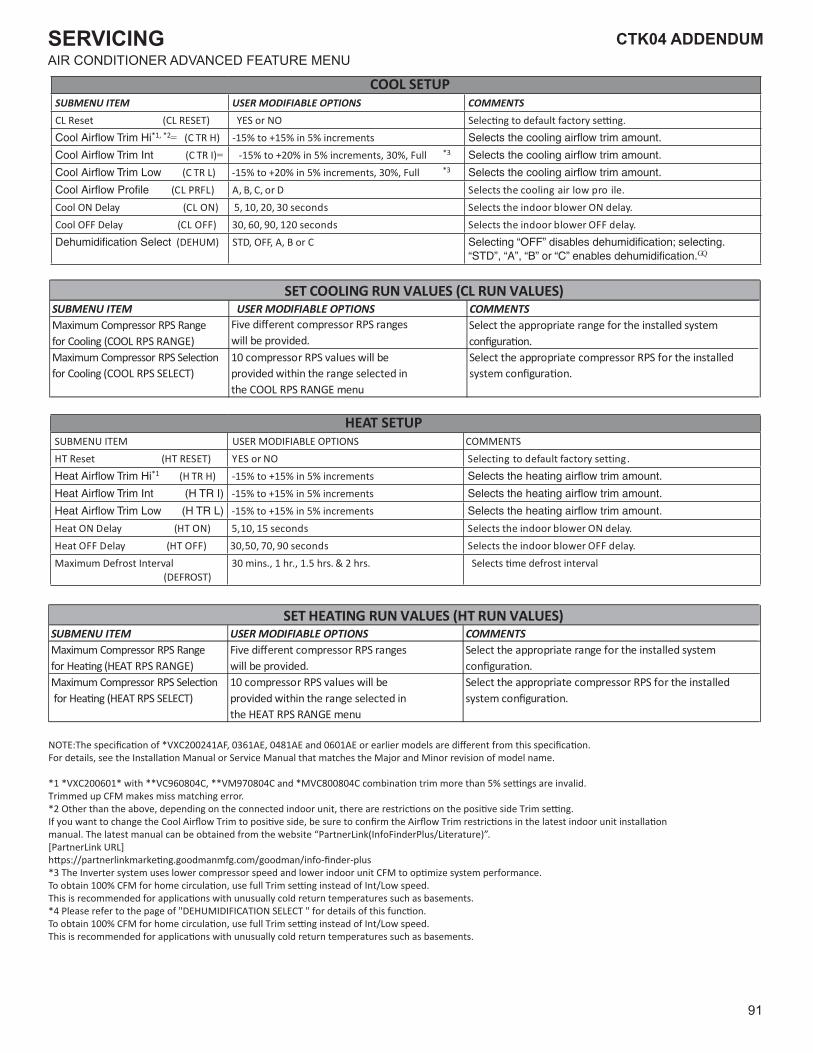
91
CTK04 ADDENDUM CTK04 ADDENDUMSERVICINGAIR CONDITIONER ADVANCED FEATURE MENU
COOL SETUPSUBMENU ITEM USER MODIFIABLE OPTIONS COMMENTSCL Reset (CL RESET)
*1, *2= (C TR H) -15% to +15% in 5% increments(C TR I)= -15% to +20% in 5% increments, 30%, Full *3
(C TR L) -15% to +20% in 5% increments, 30%, Full *3
.eliorp wolria gnilooc eht stceleSD ro ,C ,B ,A)LFRP LC(Cool ON Delay .yaled NO rewolb roodni eht stceleSsdnoces 03 ,02 ,01 ,5)NO LC(Cool OFF Delay .yaled FFO rewolb roodni eht stceleSsdnoces 021 ,09 ,06 ,03)FFO LC(
(DEHUM) STD, OFF, A, B or CGQ
SUBMENU ITEM USER MODIFIABLE OPTIONS COMMENTSMaximum Compressor RPS Range for Cooling (COOL RPS RANGE) will be provided.
Select the appropriate range for the installed system
Maximum Compressor RPS for Cooling (COOL RPS SELECT)
10 compressor RPS values will be provided within the range selected in the COOL RPS RANGE menu
Select the appropriate compressor RPS for the installed
SET COOLING RUN VALUES (CL RUN VALUES)
HEAT SETUPSUBMENU ITEM USER MODIFIABLE OPTIONS COMMENTS
.gnittes yrotcaf tluafed ot gnitceleSON ro SEY)TESER TH( teseR TH*1 (H TR H) -15% to +15% in 5% increments
-15% to +15% in 5% increments-15% to +15% in 5% increments
.yaled NO rewolb roodni eht stceleSsdnoces 51 ,01 ,5)NO TH( yaleD NO taeH .yaled FFO rewolb roodni eht stceleS sdnoces 09 ,07 ,05,03)FFO TH( yaleD FFO taeH
Maximum Defrost Interval(DEFROST)
30 mins., 1 hr., 1.5 hrs. & 2 hrs. Selects �me defrost interval
SUBMENU ITEM USER MODIFIABLE OPTIONS COMMENTSMaximum Compressor RPS Rangefor H (HEAT RPS RANGE) will be provided.
Select the appropriate range for the installed system
Maximum Compressor RPS for H RPS SELECT)
10 compressor RPS values will be provided within the range selected in the HEAT RPS RANGE menu
Select the appropriate compressor RPS for the installed
SET HEATING RUN VALUES (HT RUN VALUES)
YES or NO
NOTE:The specifica�on of *VXC200241AF, 0361AE, 0481AE and 0601AE or earlier models are different from this specifica�on. For details, see the Installa�on Manual or Service Manual that matches the Major and Minor revision of model name.
*1 *VXC200601* with **VC960804C, **VM970804C and *MVC800804C combina�on trim more than 5% se�ngs are invalid.Trimmed up CFM makes miss matching error.*2 Other than the above, depending on the connected indoor unit, there are restric�ons on the posi�ve side Trim se�ng.If you want to change the Cool Airflow Trim to posi�ve side, be sure to confirm the Airflow Trim restric�ons in the latest indoor unit installa�on manual. The latest manual can be obtained from the website “PartnerLink(InfoFinderPlus/Literature)”.[PartnerLink URL]h�ps://partnerlinkmarke�ng.goodmanmfg.com/goodman/info-finder-plus*3 The Inverter system uses lower compressor speed and lower indoor unit CFM to op�mize system performance.To obtain 100% CFM for home circula�on, use full Trim se�ng instead of Int/Low speed.This is recommended for applica�ons with unusually cold return temperatures such as basements.*4 Please refer to the page of "DEHUMIDIFICATION SELECT " for details of this func�on.To obtain 100% CFM for home circula�on, use full Trim se�ng instead of Int/Low speed.This is recommended for applica�ons with unusually cold return temperatures such as basements.
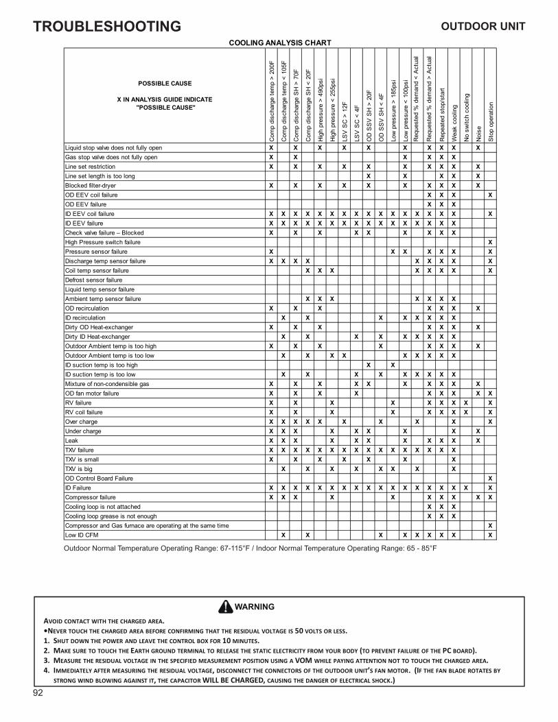
TROUBLESHOOTING
92
POSSIBLE CAUSE
X IN ANALYSIS GUIDE INDICATE "POSSIBLE CAUSE"
Com
p di
scha
rge
tem
p >
200F
Com
p di
scha
rge
tem
p <
105F
Com
p di
scha
rge
SH
> 7
0F
Com
p di
scha
rge
SH
< 2
0F
Hig
h pr
essu
re >
490
psi
Hig
h pr
essu
re <
255
psi
LSV
SC
> 1
2F
LSV
SC
< 4
F
OD
SS
V S
H >
20F
OD
SS
V S
H <
4F
Low
pre
ssur
e >
185p
si
Low
pre
ssur
e <
100p
siR
eque
sted
% d
eman
d <
Act
ual
Req
uest
ed %
dem
and
> A
ctua
l
Rep
eate
d st
op/s
tart
Wea
k co
olin
g
No
switc
h co
olin
g
Noi
se
Sto
p op
erat
ion
Liquid stop valve does not fully open X X X X X X X X X XGas stop valve does not fully open X X X X X XLine set restriction X X X X X X X X X XLine set length is too long X X X X XBlocked filter-dryer X X X X X X X X X XOD EEV coil failure X X X XOD EEV failure X X XID EEV coil failure X X X X X X X X X X X X X X X X XID EEV failure X X X X X X X X X X X X X X X XCheck valve failure – Blocked X X X X X X X X XHigh Pressure switch failure XPressure sensor failure X X X X X X XDischarge temp sensor failure X X X X X X X X XCoil temp sensor failure X X X X X X X XDefrost sensor failureLiquid temp sensor failureAmbient temp sensor failure X X X X X X XOD recirculation X X X X X X XID recirculation X X X X X X X XDirty OD Heat-exchanger X X X X X X XDirty ID Heat-exchanger X X X X X X X X XOutdoor Ambient temp is too high X X X X X X X XOutdoor Ambient temp is too low X X X X X X X X XID suction temp is too high X XID suction temp is too low X X X X X X X X XMixture of non-condensible gas X X X X X X X X X XOD fan motor failure X X X X X X X X XRV failure X X X X X X X X XRV coil failure X X X X X X X X XOver charge X X X X X X X X X XUnder charge X X X X X X X X XLeak X X X X X X X X X X XTXV failure X X X X X X X X X X X X X X X XTXV is small X X X X X X XTXV is big X X X X X X X XOD Control Board Failure XID Failure X X X X X X X X X X X X X X X X X XCompressor failure X X X X X X X X X XCooling loop is not attached X X XCooling loop grease is not enough X X XCompressor and Gas furnace are operating at the same time XLow ID CFM X X X X X X X X X
COOLING ANALYSIS CHART
Outdoor Normal Temperature Operating Range: 67-115°F / Indoor Normal Temperature Operating Range: 65 - 85°F
AVOID CONTACT WITH THE CHARGED AREA.•NEVER TOUCH THE CHARGED AREA BEFORE CONFIRMING THAT THE RESIDUAL VOLTAGE IS 50 VOLTS OR LESS.1. SHUT DOWN THE POWER AND LEAVE THE CONTROL BOX FOR 10 MINUTES.2. MAKE SURE TO TOUCH THE EARTH GROUND TERMINAL TO RELEASE THE STATIC ELECTRICITY FROM YOUR BODY (TO PREVENT FAILURE OF THE PC BOARD).3. MEASURE THE RESIDUAL VOLTAGE IN THE SPECIFIED MEASUREMENT POSITION USING A VOM WHILE PAYING ATTENTION NOT TO TOUCH THE CHARGED AREA.4. IMMEDIATELY AFTER MEASURING THE RESIDUAL VOLTAGE, DISCONNECT THE CONNECTORS OF THE OUTDOOR UNIT’S FAN MOTOR. (IF THE FAN BLADE ROTATES BY
STRONG WIND BLOWING AGAINST IT, THE CAPACITOR WILL BE CHARGED, CAUSING THE DANGER OF ELECTRICAL SHOCK.)
WARNING
OUTDOOR UNIT
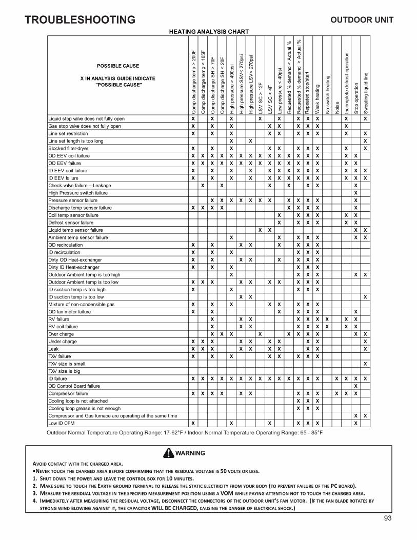
TROUBLESHOOTING
93
OUTDOOR UNIT
POSSIBLE CAUSE
X IN ANALYSIS GUIDE INDICATE "POSSIBLE CAUSE"
Com
p di
scha
rge
tem
p >
200F
Com
p di
scha
rge
tem
p <
105F
Com
p di
scha
rge
SH
> 7
0F
Com
p di
scha
rge
SH
< 2
0F
Hig
h pr
essu
re >
490
psi
Hig
h pr
essu
re S
SV
< 27
0psi
Hig
h pr
essu
re L
SV
< 27
0psi
LSV
SC
> 1
2F
LSV
SC
< 4
F
Low
pre
ssur
e <
40ps
i
Req
uest
ed %
dem
and
< A
ctua
l %
Req
uest
ed %
dem
and
> A
ctua
l %R
epea
ted
stop
/sta
rt
Wea
k he
atin
g
No
switc
h he
atin
g
Noi
se
Inco
mpl
ete
defro
st o
pera
tion
Sto
p op
erat
ion
Sw
eatin
g liq
uid
line
Liquid stop valve does not fully open X X X X X X X X X XGas stop valve does not fully open X X X X X X X X XLine set restriction X X X X X X X X X XLine set length is too long X X XBlocked filter-dryer X X X X X X X X X XOD EEV coil failure X X X X X X X X X X X X X X X XOD EEV failure X X X X X X X X X X X X X X X XID EEV coil failure X X X X X X X X X X X X XID EEV failure X X X X X X X X X X X X XCheck valve failure – Leakage X X X X X X XHigh Pressure switch failure XPressure sensor failure X X X X X X X X X X X XDischarge temp sensor failure X X X X X X X X XCoil temp sensor failure X X X X X XDefrost sensor failure X X X X X XLiquid temp sensor failure X X X XAmbient temp sensor failure X X X X X X XOD recirculation X X X X X X X XID recirculation X X X X X XDirty OD Heat-exchanger X X X X X X X XDirty ID Heat-exchanger X X X X X XOutdoor Ambient temp is too high X X X X X XOutdoor Ambient temp is too low X X X X X X X X X XID suction temp is too high X X X X XID suction temp is too low X X XMixture of non-condensible gas X X X X X X X XOD fan motor failure X X X X X X XRV failure X X X X X X X X XRV coil failure X X X X X X X X XOver charge X X X X X X X X X XUnder charge X X X X X X X X X XLeak X X X X X X X X X XTXV failure X X X X X X X XTXV size is small XTXV size is bigID failure X X X X X X X X X X X X X X X X X XOD Control Board failure XCompressor failure X X X X X X X X X X X XCooling loop is not attached X X XCooling loop grease is not enough X X XCompressor and Gas furnace are operating at the same time X XLow ID CFM X X X X X X X
HEATING ANALYSIS CHART
AVOID CONTACT WITH THE CHARGED AREA.•NEVER TOUCH THE CHARGED AREA BEFORE CONFIRMING THAT THE RESIDUAL VOLTAGE IS 50 VOLTS OR LESS.1. SHUT DOWN THE POWER AND LEAVE THE CONTROL BOX FOR 10 MINUTES.2. MAKE SURE TO TOUCH THE EARTH GROUND TERMINAL TO RELEASE THE STATIC ELECTRICITY FROM YOUR BODY (TO PREVENT FAILURE OF THE PC BOARD).3. MEASURE THE RESIDUAL VOLTAGE IN THE SPECIFIED MEASUREMENT POSITION USING A VOM WHILE PAYING ATTENTION NOT TO TOUCH THE CHARGED AREA.4. IMMEDIATELY AFTER MEASURING THE RESIDUAL VOLTAGE, DISCONNECT THE CONNECTORS OF THE OUTDOOR UNIT’S FAN MOTOR. (IF THE FAN BLADE ROTATES BY
STRONG WIND BLOWING AGAINST IT, THE CAPACITOR WILL BE CHARGED, CAUSING THE DANGER OF ELECTRICAL SHOCK.)
WARNING
Outdoor Normal Temperature Operating Range: 17-62°F / Indoor Normal Temperature Operating Range: 65 - 85°F
OUTDOOR UNIT
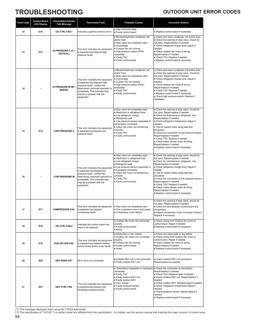
TROUBLESHOOTING
94
Fault Code Control Board LED Display
Transmitted ClimateTalk Message Thermostat Fault Probable Causes Corrective Actions
12 E12 OD CTRL FAIL1 Indicates a general memory error.● High electrical noise● Faulty control board ● Replace control board if necessary
13 E13 HI PRESSURE C (C = CRITICAL)
This error indicates the equipment is experiencing frequent high pressure faults.
● Blocked/restricted condenser coil and/or lines● Stop valve not completely open● Overcharge● Outdoor fan not running● High pressure switch (HPS) inoperable● Faulty TXV● Faulty control board
● Check and clean condenser coil and/or lines● Check the opening of stop valve, should be full open; Repair/replace if needed● Check refrigerant charge level; Adjust if needed● Check outdoor fan motor & wiring; Repair/replace if needed● Check TXV; Replace if needed● Replace control board if necessary
14 - HI PRESSURE M (M = MINOR)
This error indicates the equipment is experiencing frequent high pressure faults. Control has determined continued operation is acceptable. This indicates they may be a problem with the equipment.
● Blocked/restricted condenser coil and/or lines● Stop valve not completely open● Overcharge● Outdoor fan not running● High pressure switch (HPS) inoperable● Faulty TXV● Faulty control board
● Check and clean condenser coil and/or lines● Check the opening of stop valve, should be full open; Repair/replace if needed● Check refrigerant charge level; Adjust if needed● Check outdoor fan motor & wiring; Repair/replace if needed● Check TXV; Replace if needed● Replace control board if necessary● Check high pressure switch; Replace if necessary
15 E15 LOW PRESSURE CThis error indicates the equipment is experiencing frequent low pressure faults.
● Stop valve not completely open● Restriction in refrigerant lines● Low refrigerant charge● Refrigerant leak● Low pressure sensor inoperable or not properly connected● Indoor fan motor not functioning correctly● Faulty TXV● Faulty control board
● Check the opening of stop valve, should be full open; Repair/replace if needed● Check for restrictions in refrigerant line; Repair/replace if needed● Check refrigerant charge level; Adjust if needed● Test for system leaks using leak test procedure● Check the connection to low pressure sensor; Repair/replace if needed● Check TXV; Replace if needed● Check indoor blower motor & wiring; Repair/replace if needed● Replace control board if necessary
16 - LOW PRESSURE M
This error indicates the equipment is experiencing frequent low pressure faults. Control has determined continued operation is acceptable. This indicates they may be a problem with the equipment.
● Stop valve not completely open● Restriction in refrigerant lines● Low refrigerant charge● Refrigerant leak● Low pressure sensor inoperable or not properly connected● Indoor fan motor not functioning correctly● Faulty TXV● Faulty control board
● Check the opening of stop valve, should be full open; Repair/replace if needed● Check for restrictions in refrigerant line; Repair/replace if needed● Check refrigerant charge level; Adjust if needed● Test for system leaks using leak test procedure● Check the connection to low pressure sensor; Repair/replace if needed● Check TXV; Replace if needed● Check indoor blower motor & wiring; Repair/replace if needed● Replace control board if necessary
17 E17 COMPRESSOR FAILThis error indicates the equipment is experiencing frequent compressor faults.
● Stop valve not completely open● The compressor wire is lost phase● Compressor motor failure
● Check the opening of stop valve, should be full open; Repair/replace if needed● Check the wire between control board and compressor● Inspect compressor motor for proper function; Replace if necessary
18 E18 OD CTRL FAIL2 Indicates the control board may need to be replaced.
● Outdoor fan motor not connected properly● Faulty control board● Noise
● Check wiring from Outdoor fan motor to control board; Repair if needed.● Replace control board if necessary
19 E19 PCB OR FAN FAILThis error indicates the equipment is experiencing frequent outdoor control board and/or motor faults.
● Obstruction in fan rotation● Outdoor fan motor not connected properly● Outdoor fan not running● Faulty control borad● Noise
● Check and clean grille or any debris● Check wiring from Outdoor fan motor to control board; Repair if needed● Check outdoor fan motor & wiring. Repair/replace if needed● Replace control board if necessary
20 E20 EEV OPEN CKT EEV coil is not connected. ● Outdoor EEV coil is not connected.● Faulty outdoor EEV coil.
● Check outdoor EEV coil connection. Repair/replace as needed.
21 E21 EEV CTRL FAILThis error indicates the equipment is experiencing frequent low discharge superheat faults.
● Thermistors inoperable or improperly connected● Faulty TXV● Faulty outdoor EEV coil● Faulty outdoor EEV● Over charge● Faulty pressure sensor● Faulty control board
● Check the connection to thermistors; Repair/replace if needed● Check TXV; Replace/repair if needed● Check outdoor EEV coil; Repair/replace if needed● Check outdoor EEV; Replace/repair if needed● Check refrigerant charge level; Adjust if needed● Check pressure sensor; Repair/replace if needed● Replace control board if necessary
(*1) This message displayed when using the CTKO4 thermostat.(*2) This specification of *VXC20**1 or earlier model are different from this specification. For details, see the service manual that matches the major revisoin of model name.
OUTDOOR UNIT ERROR CODES
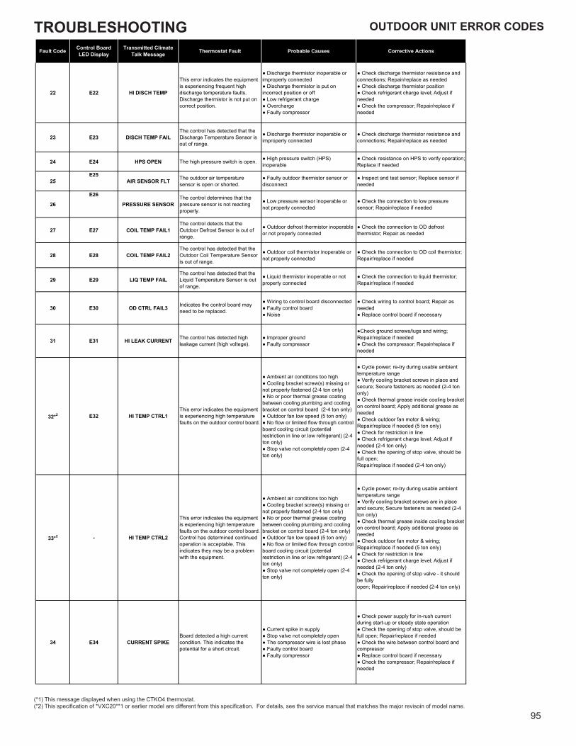
TROUBLESHOOTING
95
OUTDOOR UNIT ERROR CODES
(*1) This message displayed when using the CTKO4 thermostat.(*2) This specification of *VXC20**1 or earlier model are different from this specification. For details, see the service manual that matches the major revisoin of model name.
Fault Code Control Board LED Display
Transmitted ClimateTalk Message Thermostat Fault Probable Causes Corrective Actions
22 E22 HI DISCH TEMP
This error indicates the equipment is experiencing frequent high discharge temperature faults.Discharge thermistor is not put on correct position.
● Discharge thermistor inoperable or improperly connected● Discharge thermistor is put on incorrect position or off● Low refrigerant charge● Overcharge● Faulty compressor
● Check discharge thermistor resistance and connections; Repair/replace as needed● Check discharge thermistor position● Check refrigerant charge level; Adjust if needed● Check the compressor; Repair/replace if needed
23 E23 DISCH TEMP FAILThe control has detected that the Discharge Temperature Sensor is out of range.
● Discharge thermistor inoperable or improperly connected
● Check discharge thermistor resistance and connections; Repair/replace as needed
24 E24 HPS OPEN The high pressure switch is open. ● High pressure switch (HPS) inoperable
● Check resistance on HPS to verify operation; Replace if needed
25E25
AIR SENSOR FLT The outdoor air temperature sensor is open or shorted.
● Faulty outdoor thermistor sensor or disconnect
● Inspect and test sensor; Replace sensor if needed
26
E26
PRESSURE SENSORThe control determines that the pressure sensor is not reacting properly.
● Low pressure sensor inoperable or not properly connected
● Check the connection to low pressure sensor; Repair/replace if needed
27 E27 COIL TEMP FAIL1The control detects that the Outdoor Defrost Sensor is out of range.
● Outdoor defrost thermistor inoperable or not properly connected
● Check the connection to OD defrost thermistor; Repair as needed
28 E28 COIL TEMP FAIL2The control has detected that the Outdoor Coil Temperature Sensor is out of range.
● Outdoor coil thermistor inoperable or not properly connected
● Check the connection to OD coil thermistor; Repair/replace if needed
29 E29 LIQ TEMP FAILThe control has detected that the Liquid Temperature Sensor is out of range.
● Liquid thermistor inoperable or not properly connected
● Check the connection to liquid thermistor; Repair/replace if needed
30 E30 OD CTRL FAIL3 Indicates the control board may need to be replaced.
● Wiring to control board disconnected● Faulty control board● Noise
● Check wiring to control board; Repair as needed● Replace control board if necessary
31 E31 HI LEAK CURRENT The control has detected high leakage current (high voltege).
● Improper ground● Faulty compressor
●Check ground screws/lugs and wiring; Repair/replace if needed● Check the compressor; Repair/replace if needed
32*2 E32 HI TEMP CTRL1This error indicates the equipment is experiencing high temperature faults on the outdoor control board.
● Ambient air conditions too high● Cooling bracket screw(s) missing or not properly fastened (2-4 ton only)● No or poor thermal grease coating between cooling plumbing and cooling bracket on control board (2-4 ton only)● Outdoor fan low speed (5 ton only)● No flow or limited flow through control board cooling circuit (potential restriction in line or low refrigerant) (2-4 ton only)● Stop valve not completely open (2-4 ton only)
● Cycle power; re-try during usable ambient temperature range● Verify cooling bracket screws in place and secure; Secure fasteners as needed (2-4 ton only)● Check thermal grease inside cooling bracket on control board; Apply additional grease as needed● Check outdoor fan motor & wiring; Repair/replace if needed (5 ton only)● Check for restriction in line● Check refrigerant charge level; Adjust if needed (2-4 ton only)● Check the opening of stop valve, should be full open;Repair/replace if needed (2-4 ton only)
33*2 - HI TEMP CTRL2
This error indicates the equipment is experiencing high temperature faults on the outdoor control board. Control has determined continued operation is acceptable. This indicates they may be a problem with the equipment.
● Ambient air conditions too high● Cooling bracket screw(s) missing or not properly fastened (2-4 ton only)● No or poor thermal grease coating between cooling plumbing and cooling bracket on control board (2-4 ton only)● Outdoor fan low speed (5 ton only)● No flow or limited flow through control board cooling circuit (potential restriction in line or low refrigerant) (2-4 ton only)● Stop valve not completely open (2-4 ton only)
● Cycle power; re-try during usable ambient temperature range● Verify cooling bracket screws are in place and secure; Secure fasteners as needed (2-4 ton only)● Check thermal grease inside cooling bracket on control board; Apply additional grease as needed● Check outdoor fan motor & wiring; Repair/replace if needed (5 ton only)● Check for restriction in line● Check refrigerant charge level; Adjust if needed (2-4 ton only)● Check the opening of stop valve - it should be fullyopen; Repair/replace if needed (2-4 ton only)
34 E34 CURRENT SPIKEBoard detected a high current condition. This indicates the potential for a short circuit.
● Current spike in supply● Stop valve not completely open● The compressor wire is lost phase● Faulty control board● Faulty compressor
● Check power supply for in-rush current during start-up or steady state operation● Check the opening of stop valve, should be full open; Repair/replace if needed● Check the wire between control board and compressor● Replace control board if necessary● Check the compressor; Repair/replace if needed
OUTDOOR UNIT ERROR CODES

TROUBLESHOOTING
96
(*1) This message displayed when using the CTKO4 thermostat.(*2) This specification of *VXC20**1 or earlier model are different from this specification. For details, see the service manual that matches the major revisoin of model name.
Fault Code Control Board LED Display
Transmitted ClimateTalk Message Thermostat Fault Probable Causes Corrective Actions
35 E35 HIGH CURRENT Board detected a high current condition.
● Short circuit condition● Stop valve not completely open● Overcharge● Faulty control board● Faulty compressor
● Check installation clearances.● Check the opening of stop valve, should be full open; Repair/replace if needed● Check refrigerant charge level; Adjust if needed● Replace control board if necessary● Check the compressor; Repair/replace if needed.
36 E36 STARTUP ERRORThe control encountered an abnormal condition during the startup procedure.
● Blocked/restricted condenser coil and/or lines● The compressor wire is lost phase● Inconsistent compressor load● Faulty control board
● Check and clean condenser coil and/or lines● Check the wire between control board and compressor● Replace control board if necessary
37 E37 OD CTRL FAIL4 Indicates the control board may need to be replaced.
● Outdoor fan motor not connected properly● Faulty control board
● Check wiring from outdoor fan motor to control board; Repair if needed● Replace control board if necessary
38 E38 COMP VOLTAGE The control has detected a voltage related issue with the compressor.
● High or low voltage from supply● The compressor wire is lost phase● Faulty control board
● Correct low/high line voltage condition; Contact local utility if needed● Check the wire between control board and compressor● Replace control board if necessary
39 E39 OD CTRL FAIL5 Indicates the control board may need to be replaced.
● Thermistors inoperable or improperly connected● Faulty control board
● Check the connection to thermistors; Repair/replace if needed● Replace control board if necessary
40 E40 COMP MISMATCHControl determines that its compressor requirement is different than the compressor capability.
● Bluetooth® Shared Data Loader BTSDL01 not correct● Control board mismatch
● Check Bluetooth® Shared Data Loader BTSDL01 data vs. air conditioner model● Verify control board size vs. air conditioner model; Replace control board if necessary
41 E41 LOW REFRIGERANT The control has detected a low refrigerant condition.
● Refrigerant leak● Low refrigerant charge● Thermisters inoperable or not properly connected
● Test for system leaks using leak test procedure● Check refrigerant charge level; Adjust if needed● Checkthe connection to thermistor; Repair/replace if needed
42 E42 LOW LINE VOLT Control detects a low power supply voltage condition. ● Low line voltage supply
● Check circuit breakers and fuses; Replace if needed● Verify unit is connected to power supply as specified on rating plate● Correct low line voltage condition; Contact local utility ifneeded
43 E43 HIGH LINE VOLT Control detects a high power supply voltage condition. ● High line voltage supply
● Verify unit is connected to power supply as specified on rating plate● Correct high line voltage condition; Contact local utilityif needed
44 E44 OP TEMP RANGE
The control detects the outdoor temperature outside recommended operational range. Unit may continue to operate normally.
● Ambient air conditions too high or low
● Cycle power; re-try during usable ambient temperature range
45 E45 NO COOLING TEST
The control is unable to start the Cooling mode test because indoor heat has been turned on by thermostat. Please set thermostat to off position.
● Heat provided by secondary heating source
● Turn off heater using thermostat before running AHRI mode
46 E46 NO HEATING TEST
The control is unable to sart the Heating mode test becaue indoor heat has been turned on by thermostat. Please set thermostat to off position.
● Heat provided by secondary heating source
● Turn off heater using thermostat before running AHRI mode
47 E47 NO SYS VER TEST
The control is unable to start the System Verification test because indoor heat has been turned on by thermostat. Please set thermostat to off position.
● Heat provided by secondary heating source
● Turn off heater using thermostat before operation
48 E48 NO PUMP DOWN
The control is unable to enter the Pump Down Mode because indoor heat has been turned on by thermostat. Please set thermostat to off position.
● Heat provided by secondary heating source
● Turn off heater using thermostat before operation
49 E49 NO CHARGE MODE
The control is unable to enter Charging Mode because indoor heat has been turned on by thermostat. Please set thermostat to off position.
● Heat provided by secondary heating source
● Turn off heater using thermostat before operation
50 E50 LINE VOLT CTRL
This indicates there is a voltage issue on the control board. See service manual for troubleshooting information.
● High or low voltage from supply● Faulty control board
● Correct low/high line voltage condition; Contact local utility if needed● Replace control board if necessary
51*2 E51 OD COMM ERROR
This indicates potential communication issues have been detected by the outdoor control board.
● Communication wiring disconnected ● Check communication wiring; Repair as needed
52 - COMP FAIL MINOR
This error indicates the equipment is experiencing frequent compressor faults. Control has determined continued operation is acceptable. This indicates they may be a problem with the equipment.
● Stop valve not completely open● The compressor wire is lost phase● Compressor motor failure
● Check the opening of stop valve, should be full open; Repair/replace if needed● Check the wire between control board and compressor● Inspect compressor motor for proper function; Replace if necessary
OUTDOOR UNIT ERROR CODES
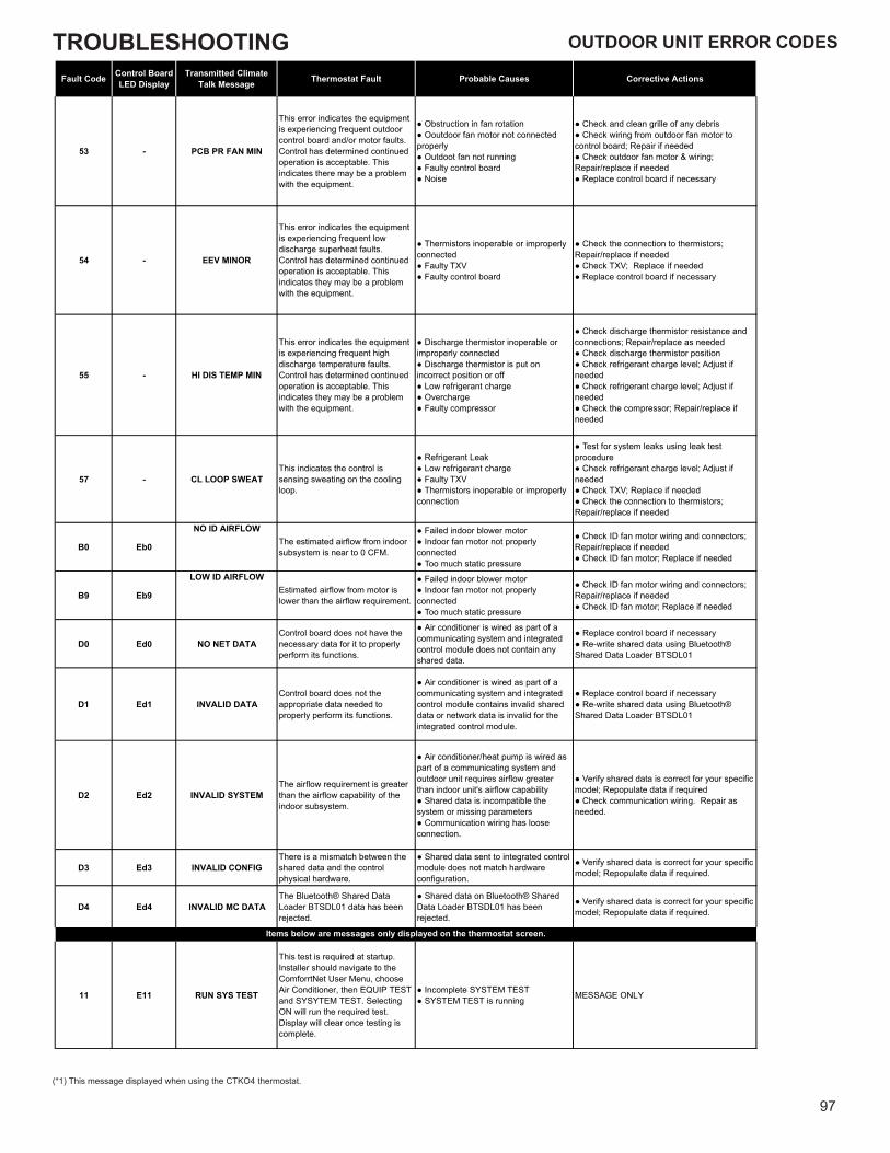
TROUBLESHOOTING
97
(*1) This message displayed when using the CTKO4 thermostat.
Fault Code Control Board LED Display
Transmitted ClimateTalk Message Thermostat Fault Probable Causes Corrective Actions
53 - PCB PR FAN MIN
This error indicates the equipment is experiencing frequent outdoor control board and/or motor faults.Control has determined continued operation is acceptable. This indicates there may be a problem with the equipment.
● Obstruction in fan rotation● Ooutdoor fan motor not connected properly● Outdoot fan not running● Faulty control board● Noise
● Check and clean grille of any debris● Check wiring from outdoor fan motor to control board; Repair if needed● Check outdoor fan motor & wiring; Repair/replace if needed● Replace control board if necessary
54 - EEV MINOR
This error indicates the equipment is experiencing frequent low discharge superheat faults.Control has determined continued operation is acceptable. This indicates they may be a problem with the equipment.
● Thermistors inoperable or improperly connected● Faulty TXV● Faulty control board
● Check the connection to thermistors; Repair/replace if needed● Check TXV; Replace if needed● Replace control board if necessary
55 - HI DIS TEMP MIN
This error indicates the equipment is experiencing frequent high discharge temperature faults. Control has determined continued operation is acceptable. This indicates they may be a problem with the equipment.
● Discharge thermistor inoperable or improperly connected● Discharge thermistor is put on incorrect position or off● Low refrigerant charge● Overcharge● Faulty compressor
● Check discharge thermistor resistance and connections; Repair/replace as needed● Check discharge thermistor position● Check refrigerant charge level; Adjust if needed● Check refrigerant charge level; Adjust if needed● Check the compressor; Repair/replace if needed
57 - CL LOOP SWEATThis indicates the control is sensing sweating on the cooling loop.
● Refrigerant Leak● Low refrigerant charge● Faulty TXV● Thermistors inoperable or improperly connection
● Test for system leaks using leak test procedure● Check refrigerant charge level; Adjust if needed● Check TXV; Replace if needed● Check the connection to thermistors; Repair/replace if needed
B0 Eb0
NO ID AIRFLOWThe estimated airflow from indoor subsystem is near to 0 CFM.
● Failed indoor blower motor● Indoor fan motor not properly connected● Too much static pressure
● Check ID fan motor wiring and connectors; Repair/replace if needed● Check ID fan motor; Replace if needed
B9 Eb9
LOW ID AIRFLOWEstimated airflow from motor is lower than the airflow requirement.
● Failed indoor blower motor● Indoor fan motor not properly connected● Too much static pressure
● Check ID fan motor wiring and connectors; Repair/replace if needed● Check ID fan motor; Replace if needed
D0 Ed0 NO NET DATAControl board does not have the necessary data for it to properly perform its functions.
● Air conditioner is wired as part of a communicating system and integrated control module does not contain any shared data.
● Replace control board if necessary● Re-write shared data using Bluetooth® Shared Data Loader BTSDL01
D1 Ed1 INVALID DATAControl board does not the appropriate data needed to properly perform its functions.
● Air conditioner is wired as part of a communicating system and integrated control module contains invalid shared data or network data is invalid for the integrated control module.
● Replace control board if necessary● Re-write shared data using Bluetooth® Shared Data Loader BTSDL01
D2 Ed2 INVALID SYSTEMThe airflow requirement is greater than the airflow capability of the indoor subsystem.
● Air conditioner/heat pump is wired as part of a communicating system and outdoor unit requires airflow greater than indoor unit's airflow capability● Shared data is incompatible the system or missing parameters● Communication wiring has loose connection.
● Verify shared data is correct for your specific model; Repopulate data if required● Check communication wiring. Repair as needed.
D3 Ed3 INVALID CONFIGThere is a mismatch between the shared data and the control physical hardware.
● Shared data sent to integrated control module does not match hardware configuration.
● Verify shared data is correct for your specific model; Repopulate data if required.
D4 Ed4 INVALID MC DATAThe Bluetooth® Shared Data Loader BTSDL01 data has been rejected.
● Shared data on Bluetooth® Shared Data Loader BTSDL01 has been rejected.
● Verify shared data is correct for your specific model; Repopulate data if required.
11 E11 RUN SYS TEST
This test is required at startup. Installer should navigate to the ComforrtNet User Menu, choose Air Conditioner, then EQUIP TEST and SYSYTEM TEST. Selecting ON will run the required test. Display will clear once testing is complete.
● Incomplete SYSTEM TEST● SYSTEM TEST is running MESSAGE ONLY
Items below are messages only displayed on the thermostat screen.
OUTDOOR UNIT ERROR CODES
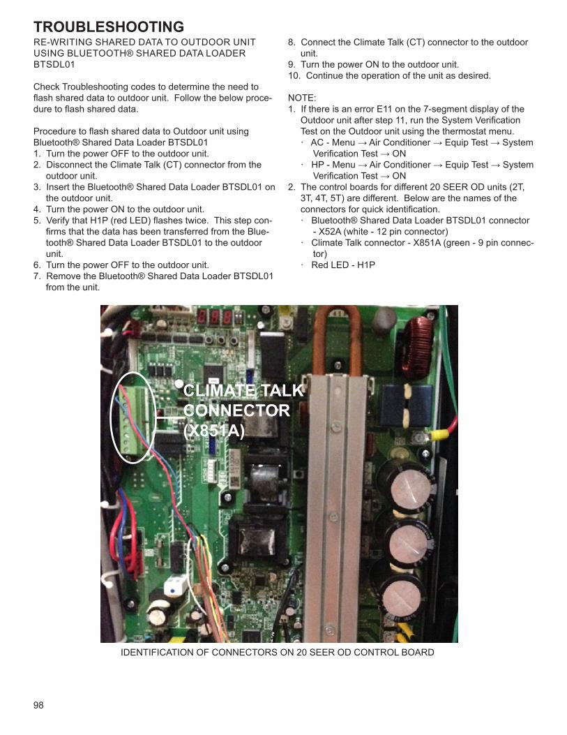
TROUBLESHOOTING
98
RE-WRITING SHARED DATA TO OUTDOOR UNIT USING BLUETOOTH® SHARED DATA LOADER BTSDL01
Check Troubleshooting codes to determine the need to flash shared data to outdoor unit. Follow the below proce-dure to flash shared data.
Procedure to flash shared data to Outdoor unit using Bluetooth® Shared Data Loader BTSDL011. Turn the power OFF to the outdoor unit.2. Disconnect the Climate Talk (CT) connector from the
outdoor unit.3. Insert the Bluetooth® Shared Data Loader BTSDL01 on
the outdoor unit.4. Turn the power ON to the outdoor unit.5. Verify that H1P (red LED) flashes twice. This step con-
firms that the data has been transferred from the Blue-tooth® Shared Data Loader BTSDL01 to the outdoor unit.
6. Turn the power OFF to the outdoor unit.7. Remove the Bluetooth® Shared Data Loader BTSDL01
from the unit.
8. Connect the Climate Talk (CT) connector to the outdoor unit.
9. Turn the power ON to the outdoor unit.10. Continue the operation of the unit as desired.
NOTE:1. If there is an error E11 on the 7-segment display of the
Outdoor unit after step 11, run the System Verification Test on the Outdoor unit using the thermostat menu.· AC - Menu → Air Conditioner → Equip Test → System
Verification Test → ON· HP - Menu → Air Conditioner → Equip Test → System
Verification Test → ON2. The control boards for different 20 SEER OD units (2T,
3T, 4T, 5T) are different. Below are the names of the connectors for quick identification.· Bluetooth® Shared Data Loader BTSDL01 connector
- X52A (white - 12 pin connector)· Climate Talk connector - X851A (green - 9 pin connec-
tor)· Red LED - H1P
IDENTIFICATION OF CONNECTORS ON 20 SEER OD CONTROL BOARD
CLIMATE TALK CONNECTOR (X851A)
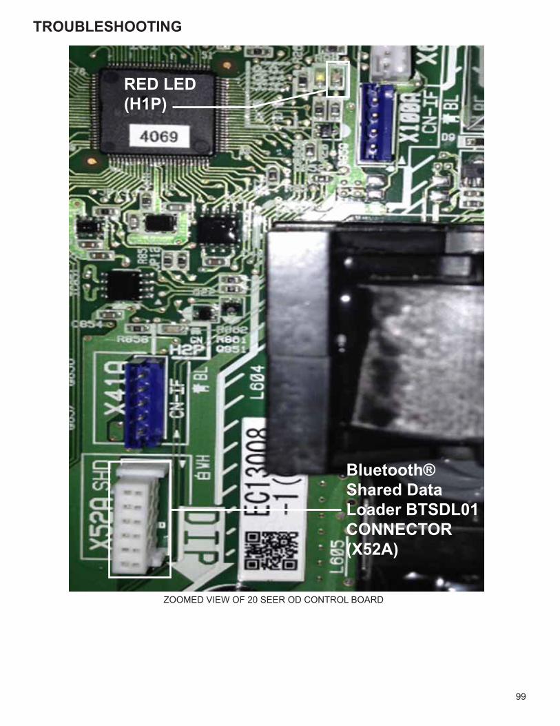
TROUBLESHOOTING
99
RED LED(H1P)
Bluetooth® Shared Data Loader BTSDL01CONNECTOR(X52A)
ZOOMED VIEW OF 20 SEER OD CONTROL BOARD
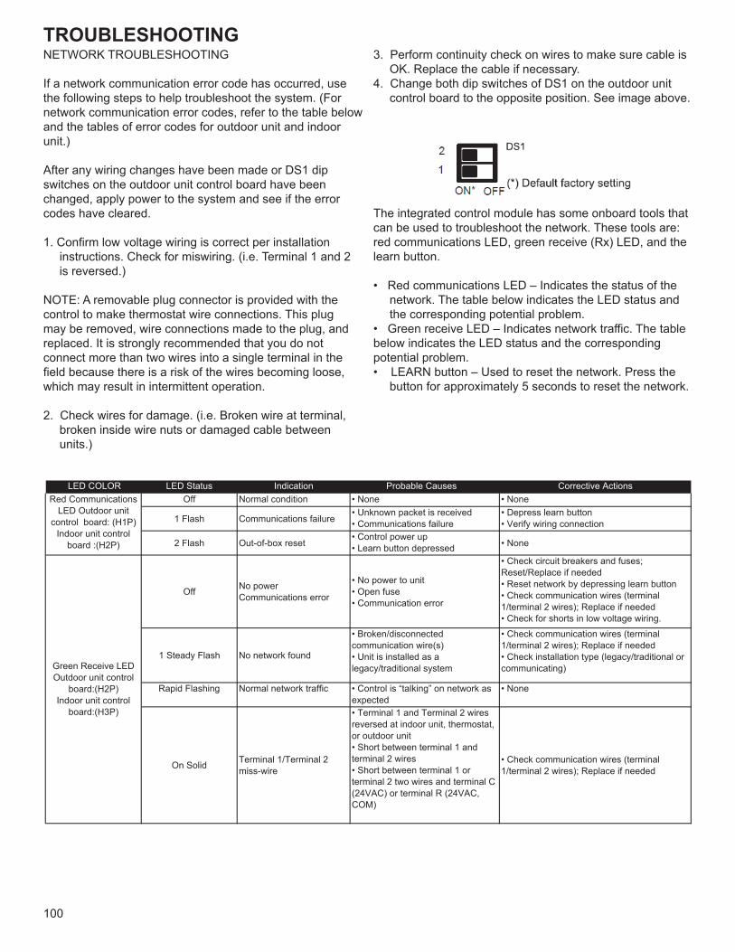
TROUBLESHOOTING
100
NETWORK TROUBLESHOOTING
If a network communication error code has occurred, usethe following steps to help troubleshoot the system. (Fornetwork communication error codes, refer to the table belowand the tables of error codes for outdoor unit and indoorunit.)
After any wiring changes have been made or DS1 dipswitches on the outdoor unit control board have beenchanged, apply power to the system and see if the errorcodes have cleared.
1. Confirm low voltage wiring is correct per installation instructions. Check for miswiring. (i.e. Terminal 1 and 2 is reversed.)
NOTE: A removable plug connector is provided with thecontrol to make thermostat wire connections. This plugmay be removed, wire connections made to the plug, andreplaced. It is strongly recommended that you do notconnect more than two wires into a single terminal in thefield because there is a risk of the wires becoming loose,which may result in intermittent operation.
2. Check wires for damage. (i.e. Broken wire at terminal, broken inside wire nuts or damaged cable between units.)
3. Perform continuity check on wires to make sure cable is OK. Replace the cable if necessary.
4. Change both dip switches of DS1 on the outdoor unit control board to the opposite position. See image above.
The integrated control module has some onboard tools thatcan be used to troubleshoot the network. These tools are: red communications LED, green receive (Rx) LED, and the learn button.
• Red communications LED – Indicates the status of the network. The table below indicates the LED status and the corresponding potential problem.
• Green receive LED – Indicates network traffic. The tablebelow indicates the LED status and the correspondingpotential problem.• LEARN button – Used to reset the network. Press the
button for approximately 5 seconds to reset the network.
LED COLOR LED Status Indication Probable Causes Corrective ActionsOff Normal condition • None • None
1 Flash Communications failure• Unknown packet is received• Communications failure
• Depress learn button• Verify wiring connection
2 Flash Out-of-box reset• Control power up• Learn button depressed • None
Off No power Communications error
• No power to unit• Open fuse• Communication error
• Check circuit breakers and fuses; Reset/Replace if needed• Reset network by depressing learn button• Check communication wires (terminal 1/terminal 2 wires); Replace if needed• Check for shorts in low voltage wiring.
1 Steady Flash No network found
• Broken/disconnected communication wire(s)• Unit is installed as a legacy/traditional system
• Check communication wires (terminal 1/terminal 2 wires); Replace if needed• Check installation type (legacy/traditional or communicating)
Rapid Flashing Normal network traffic • Control is “talking” on network as expected
• None
On Solid Terminal 1/Terminal 2 miss-wire
• Terminal 1 and Terminal 2 wires reversed at indoor unit, thermostat, or outdoor unit• Short between terminal 1 and terminal 2 wires• Short between terminal 1 or terminal 2 two wires and terminal C (24VAC) or terminal R (24VAC, COM)
• Check communication wires (terminal 1/terminal 2 wires); Replace if needed
Red Communications LED Outdoor unit
control board: (H1P)Indoor unit control
board :(H2P)
Green Receive LED Outdoor unit control
board:(H2P)Indoor unit control
board:(H3P)
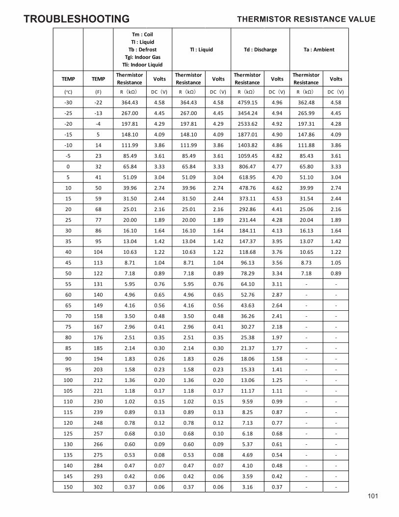
TROUBLESHOOTING
101
TEMP TEMPThermistorResistance Volts
ThermistorResistance Volts
ThermistorResistance Volts
ThermistorResistance Volts
(℃) (F) R(kΩ) DC(V) R(kΩ) DC(V) R(kΩ) DC(V) R(kΩ) DC(V)
-30 -22 364.43 4.58 364.43 4.58 4759.15 4.96 362.48 4.58
-25 -13 267.00 4.45 267.00 4.45 3454.24 4.94 265.99 4.45
-20 -4 197.81 4.29 197.81 4.29 2533.62 4.92 197.31 4.28
-15 5 148.10 4.09 148.10 4.09 1877.01 4.90 147.86 4.09
-10 14 111.99 3.86 111.99 3.86 1403.82 4.86 111.88 3.86
-5 23 85.49 3.61 85.49 3.61 1059.45 4.82 85.43 3.61
0 32 65.84 3.33 65.84 3.33 806.47 4.77 65.80 3.33
5 41 51.09 3.04 51.09 3.04 618.95 4.70 51.10 3.04
10 50 39.96 2.74 39.96 2.74 478.76 4.62 39.99 2.74
15 59 31.50 2.44 31.50 2.44 373.11 4.53 31.54 2.44
20 68 25.01 2.16 25.01 2.16 292.86 4.41 25.06 2.16
25 77 20.00 1.89 20.00 1.89 231.44 4.28 20.04 1.89
30 86 16.10 1.64 16.10 1.64 184.11 4.13 16.13 1.64
35 95 13.04 1.42 13.04 1.42 147.37 3.95 13.07 1.42
40 104 10.63 1.22 10.63 1.22 118.68 3.76 10.65 1.22
45 113 8.71 1.04 8.71 1.04 96.13 3.56 8.73 1.05
50 122 7.18 0.89 7.18 0.89 78.29 3.34 7.18 0.89
55 131 5.95 0.76 5.95 0.76 64.10 3.11 - -
60 140 4.96 0.65 4.96 0.65 52.76 2.87 - -
65 149 4.16 0.56 4.16 0.56 43.63 2.64 - -
70 158 3.50 0.48 3.50 0.48 36.26 2.41 - -
75 167 2.96 0.41 2.96 0.41 30.27 2.18 - -
80 176 2.51 0.35 2.51 0.35 25.38 1.97 - -
85 185 2.14 0.30 2.14 0.30 21.37 1.77 - -
90 194 1.83 0.26 1.83 0.26 18.06 1.58 - -
95 203 1.58 0.23 1.58 0.23 15.33 1.41 - -
100 212 1.36 0.20 1.36 0.20 13.06 1.25 - -
105 221 1.18 0.17 1.18 0.17 11.17 1.11 - -
110 230 1.02 0.15 1.02 0.15 9.59 0.99 - -
115 239 0.89 0.13 0.89 0.13 8.25 0.87 - -
120 248 0.78 0.12 0.78 0.12 7.13 0.77 - -
125 257 0.68 0.10 0.68 0.10 6.18 0.68 - -
130 266 0.60 0.09 0.60 0.09 5.37 0.61 - -
135 275 0.53 0.08 0.53 0.08 4.69 0.54 - -
140 284 0.47 0.07 0.47 0.07 4.10 0.48 - -
145 293 0.42 0.06 0.42 0.06 3.59 0.42 - -
150 302 0.37 0.06 0.37 0.06 3.16 0.37 - -
Tm : CoilTI : Liquid
Tb : DefrostTgi: Indoor Gas
Tli: Indoor Liquid
Tl : Liquid Td : Discharge Ta : Ambient
THERMISTOR RESISTANCE VALUE
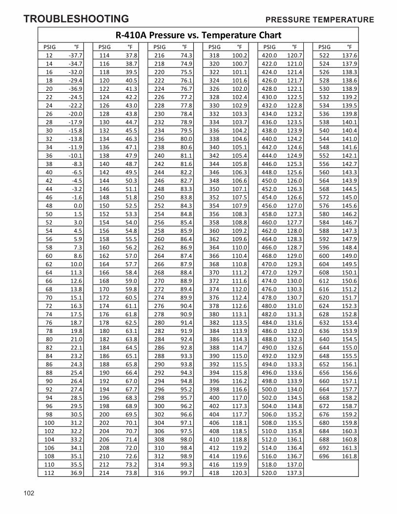
TROUBLESHOOTING
102
PSIG °F PSIG °F PSIG °F PSIG °F PSIG °F PSIG °F12 -37.7 114 37.8 216 74.3 318 100.2 420.0 120.7 522 137.614 -34.7 116 38.7 218 74.9 320 100.7 422.0 121.0 524 137.916 -32.0 118 39.5 220 75.5 322 101.1 424.0 121.4 526 138.318 -29.4 120 40.5 222 76.1 324 101.6 426.0 121.7 528 138.620 -36.9 122 41.3 224 76.7 326 102.0 428.0 122.1 530 138.922 -24.5 124 42.2 226 77.2 328 102.4 430.0 122.5 532 139.224 -22.2 126 43.0 228 77.8 330 102.9 432.0 122.8 534 139.526 -20.0 128 43.8 230 78.4 332 103.3 434.0 123.2 536 139.828 -17.9 130 44.7 232 78.9 334 103.7 436.0 123.5 538 140.130 -15.8 132 45.5 234 79.5 336 104.2 438.0 123.9 540 140.432 -13.8 134 46.3 236 80.0 338 104.6 440.0 124.2 544 141.034 -11.9 136 47.1 238 80.6 340 105.1 442.0 124.6 548 141.636 -10.1 138 47.9 240 81.1 342 105.4 444.0 124.9 552 142.138 -8.3 140 48.7 242 81.6 344 105.8 446.0 125.3 556 142.740 -6.5 142 49.5 244 82.2 346 106.3 448.0 125.6 560 143.342 -4.5 144 50.3 246 82.7 348 106.6 450.0 126.0 564 143.944 -3.2 146 51.1 248 83.3 350 107.1 452.0 126.3 568 144.546 -1.6 148 51.8 250 83.8 352 107.5 454.0 126.6 572 145.048 0.0 150 52.5 252 84.3 354 107.9 456.0 127.0 576 145.650 1.5 152 53.3 254 84.8 356 108.3 458.0 127.3 580 146.252 3.0 154 54.0 256 85.4 358 108.8 460.0 127.7 584 146.754 4.5 156 54.8 258 85.9 360 109.2 462.0 128.0 588 147.356 5.9 158 55.5 260 86.4 362 109.6 464.0 128.3 592 147.958 7.3 160 56.2 262 86.9 364 110.0 466.0 128.7 596 148.460 8.6 162 57.0 264 87.4 366 110.4 468.0 129.0 600 149.062 10.0 164 57.7 266 87.9 368 110.8 470.0 129.3 604 149.564 11.3 166 58.4 268 88.4 370 111.2 472.0 129.7 608 150.166 12.6 168 59.0 270 88.9 372 111.6 474.0 130.0 612 150.668 13.8 170 59.8 272 89.4 374 112.0 476.0 130.3 616 151.270 15.1 172 60.5 274 89.9 376 112.4 478.0 130.7 620 151.772 16.3 174 61.1 276 90.4 378 112.6 480.0 131.0 624 152.374 17.5 176 61.8 278 90.9 380 113.1 482.0 131.3 628 152.876 18.7 178 62.5 280 91.4 382 113.5 484.0 131.6 632 153.478 19.8 180 63.1 282 91.9 384 113.9 486.0 132.0 636 153.980 21.0 182 63.8 284 92.4 386 114.3 488.0 132.3 640 154.582 22.1 184 64.5 286 92.8 388 114.7 490.0 132.6 644 155.084 23.2 186 65.1 288 93.3 390 115.0 492.0 132.9 648 155.586 24.3 188 65.8 290 93.8 392 115.5 494.0 133.3 652 156.188 25.4 190 66.4 292 94.3 394 115.8 496.0 133.6 656 156.690 26.4 192 67.0 294 94.8 396 116.2 498.0 133.9 660 157.192 27.4 194 67.7 296 95.2 398 116.6 500.0 134.0 664 157.794 28.5 196 68.3 298 95.7 400 117.0 502.0 134.5 668 158.296 29.5 198 68.9 300 96.2 402 117.3 504.0 134.8 672 158.798 30.5 200 69.5 302 96.6 404 117.7 506.0 135.2 676 159.2
100 31.2 202 70.1 304 97.1 406 118.1 508.0 135.5 680 159.8102 32.2 204 70.7 306 97.5 408 118.5 510.0 135.8 684 160.3104 33.2 206 71.4 308 98.0 410 118.8 512.0 136.1 688 160.8106 34.1 208 72.0 310 98.4 412 119.2 514.0 136.4 692 161.3108 35.1 210 72.6 312 98.9 414 119.6 516.0 136.7 696 161.8110 35.5 212 73.2 314 99.3 416 119.9 518.0 137.0112 36.9 214 73.8 316 99.7 418 120.3 520.0 137.3
R-410A Pressure vs. Temperature ChartPRESSURE TEMPERATURE
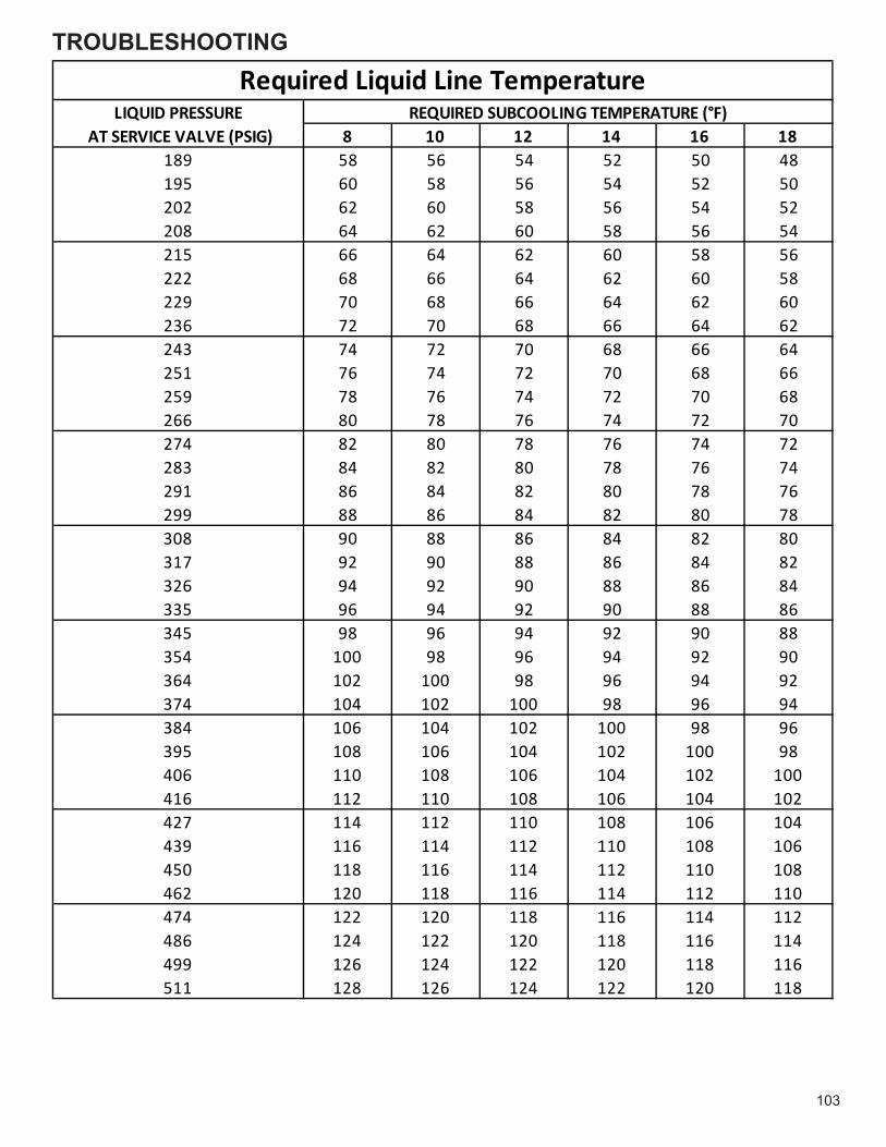
TROUBLESHOOTING
103
LIQUID PRESSURE AT SERVICE VALVE (PSIG) 8 10 12 14 16 18
189 58 56 54 52 50 48195 60 58 56 54 52 50202 62 60 58 56 54 52208 64 62 60 58 56 54215 66 64 62 60 58 56222 68 66 64 62 60 58229 70 68 66 64 62 60236 72 70 68 66 64 62243 74 72 70 68 66 64251 76 74 72 70 68 66259 78 76 74 72 70 68266 80 78 76 74 72 70274 82 80 78 76 74 72283 84 82 80 78 76 74291 86 84 82 80 78 76299 88 86 84 82 80 78308 90 88 86 84 82 80317 92 90 88 86 84 82326 94 92 90 88 86 84335 96 94 92 90 88 86345 98 96 94 92 90 88354 100 98 96 94 92 90364 102 100 98 96 94 92374 104 102 100 98 96 94384 106 104 102 100 98 96395 108 106 104 102 100 98406 110 108 106 104 102 100416 112 110 108 106 104 102427 114 112 110 108 106 104439 116 114 112 110 108 106450 118 116 114 112 110 108462 120 118 116 114 112 110474 122 120 118 116 114 112486 124 122 120 118 116 114499 126 124 122 120 118 116511 128 126 124 122 120 118
Required Liquid Line TemperatureREQUIRED SUBCOOLING TEMPERATURE (°F)
PRESSURE TEMPERATURE
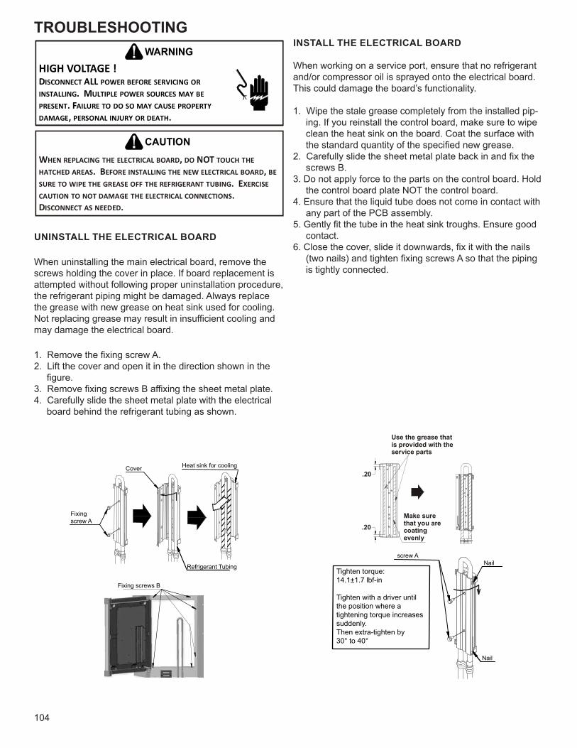
TROUBLESHOOTING
104
HIGH VOLTAGE !DISCONNECT ALL POWER BEFORE SERVICING OR INSTALLING. MULTIPLE POWER SOURCES MAY BE PRESENT. FAILURE TO DO SO MAY CAUSE PROPERTY DAMAGE, PERSONAL INJURY OR DEATH.
WARNING
WHEN REPLACING THE ELECTRICAL BOARD, DO NOT TOUCH THE HATCHED AREAS. BEFORE INSTALLING THE NEW ELECTRICAL BOARD, BE SURE TO WIPE THE GREASE OFF THE REFRIGERANT TUBING. EXERCISE CAUTION TO NOT DAMAGE THE ELECTRICAL CONNECTIONS. DISCONNECT AS NEEDED.
CAUTION
UNINSTALL THE ELECTRICAL BOARD
When uninstalling the main electrical board, remove the screws holding the cover in place. If board replacement is attempted without following proper uninstallation procedure, the refrigerant piping might be damaged. Always replace the grease with new grease on heat sink used for cooling. Not replacing grease may result in insufficient cooling and may damage the electrical board.
1. Remove the fixing screw A.2. Lift the cover and open it in the direction shown in the
figure.3. Remove fixing screws B affixing the sheet metal plate.4. Carefully slide the sheet metal plate with the electrical
board behind the refrigerant tubing as shown.
Use the grease thatis provided with theservice parts
.20
.20Make surethat you arecoating evenly
Cover Heat sink for cooling
Fixingscrew A
Refrigerant Tubing
Fixing screws B
screw ANail
Nail
Tighten torque:14.1±1.7 lbf-in
Tighten with a driver untilthe position where a tightening torque increases suddenly.Then extra-tighten by 30° to 40°
INSTALL THE ELECTRICAL BOARD
When working on a service port, ensure that no refrigerant and/or compressor oil is sprayed onto the electrical board. This could damage the board’s functionality.
1. Wipe the stale grease completely from the installed pip-ing. If you reinstall the control board, make sure to wipe clean the heat sink on the board. Coat the surface with the standard quantity of the specified new grease.
2. Carefully slide the sheet metal plate back in and fix the screws B.
3. Do not apply force to the parts on the control board. Hold the control board plate NOT the control board.
4. Ensure that the liquid tube does not come in contact with any part of the PCB assembly.
5. Gently fit the tube in the heat sink troughs. Ensure good contact.
6. Close the cover, slide it downwards, fix it with the nails (two nails) and tighten fixing screws A so that the piping is tightly connected.
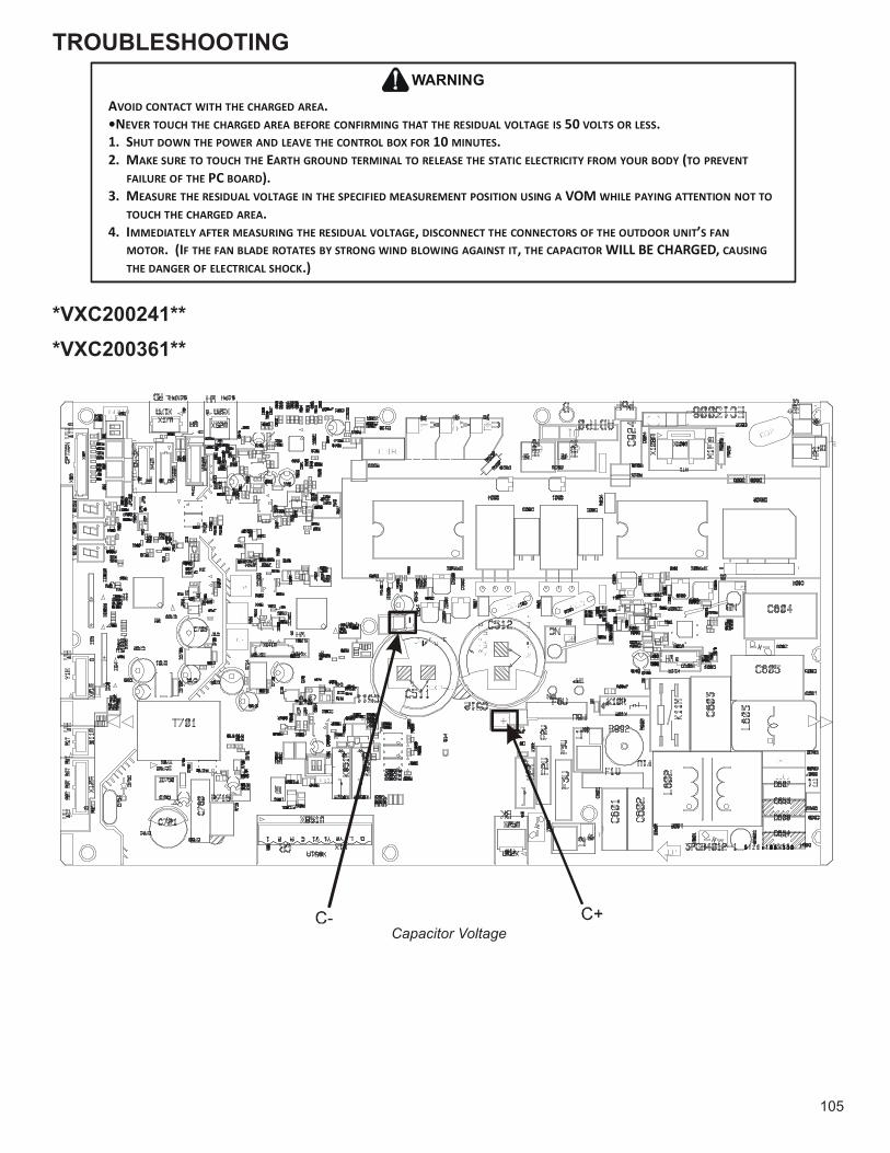
TROUBLESHOOTING
105
*VXC200241***VXC200361**
AVOID CONTACT WITH THE CHARGED AREA.•NEVER TOUCH THE CHARGED AREA BEFORE CONFIRMING THAT THE RESIDUAL VOLTAGE IS 50 VOLTS OR LESS.1. SHUT DOWN THE POWER AND LEAVE THE CONTROL BOX FOR 10 MINUTES.2. MAKE SURE TO TOUCH THE EARTH GROUND TERMINAL TO RELEASE THE STATIC ELECTRICITY FROM YOUR BODY (TO PREVENT
FAILURE OF THE PC BOARD).3. MEASURE THE RESIDUAL VOLTAGE IN THE SPECIFIED MEASUREMENT POSITION USING A VOM WHILE PAYING ATTENTION NOT TO
TOUCH THE CHARGED AREA.4. IMMEDIATELY AFTER MEASURING THE RESIDUAL VOLTAGE, DISCONNECT THE CONNECTORS OF THE OUTDOOR UNIT’S FAN
MOTOR. (IF THE FAN BLADE ROTATES BY STRONG WIND BLOWING AGAINST IT, THE CAPACITOR WILL BE CHARGED, CAUSING THE DANGER OF ELECTRICAL SHOCK.)
WARNING
Capacitor Voltage
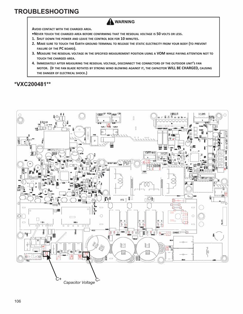
TROUBLESHOOTING
106
*VXC200481**
AVOID CONTACT WITH THE CHARGED AREA.•NEVER TOUCH THE CHARGED AREA BEFORE CONFIRMING THAT THE RESIDUAL VOLTAGE IS 50 VOLTS OR LESS.1. SHUT DOWN THE POWER AND LEAVE THE CONTROL BOX FOR 10 MINUTES.2. MAKE SURE TO TOUCH THE EARTH GROUND TERMINAL TO RELEASE THE STATIC ELECTRICITY FROM YOUR BODY (TO PREVENT
FAILURE OF THE PC BOARD).3. MEASURE THE RESIDUAL VOLTAGE IN THE SPECIFIED MEASUREMENT POSITION USING A VOM WHILE PAYING ATTENTION NOT TO
TOUCH THE CHARGED AREA.4. IMMEDIATELY AFTER MEASURING THE RESIDUAL VOLTAGE, DISCONNECT THE CONNECTORS OF THE OUTDOOR UNIT’S FAN
MOTOR. (IF THE FAN BLADE ROTATES BY STRONG WIND BLOWING AGAINST IT, THE CAPACITOR WILL BE CHARGED, CAUSING THE DANGER OF ELECTRICAL SHOCK.)
WARNING
C+ C-Capacitor Voltage
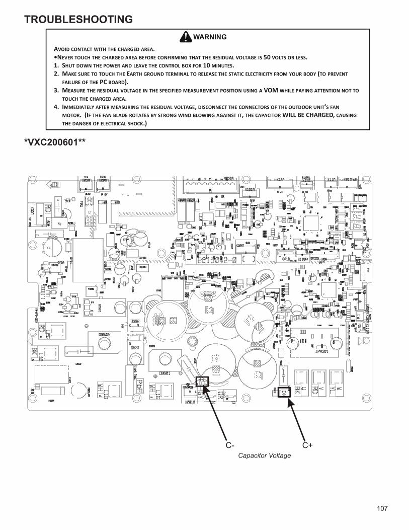
TROUBLESHOOTING
107
*VXC200601**
AVOID CONTACT WITH THE CHARGED AREA.•NEVER TOUCH THE CHARGED AREA BEFORE CONFIRMING THAT THE RESIDUAL VOLTAGE IS 50 VOLTS OR LESS.1. SHUT DOWN THE POWER AND LEAVE THE CONTROL BOX FOR 10 MINUTES.2. MAKE SURE TO TOUCH THE EARTH GROUND TERMINAL TO RELEASE THE STATIC ELECTRICITY FROM YOUR BODY (TO PREVENT
FAILURE OF THE PC BOARD).3. MEASURE THE RESIDUAL VOLTAGE IN THE SPECIFIED MEASUREMENT POSITION USING A VOM WHILE PAYING ATTENTION NOT TO
TOUCH THE CHARGED AREA.4. IMMEDIATELY AFTER MEASURING THE RESIDUAL VOLTAGE, DISCONNECT THE CONNECTORS OF THE OUTDOOR UNIT’S FAN
MOTOR. (IF THE FAN BLADE ROTATES BY STRONG WIND BLOWING AGAINST IT, THE CAPACITOR WILL BE CHARGED, CAUSING THE DANGER OF ELECTRICAL SHOCK.)
WARNING
Capacitor VoltageC+C-
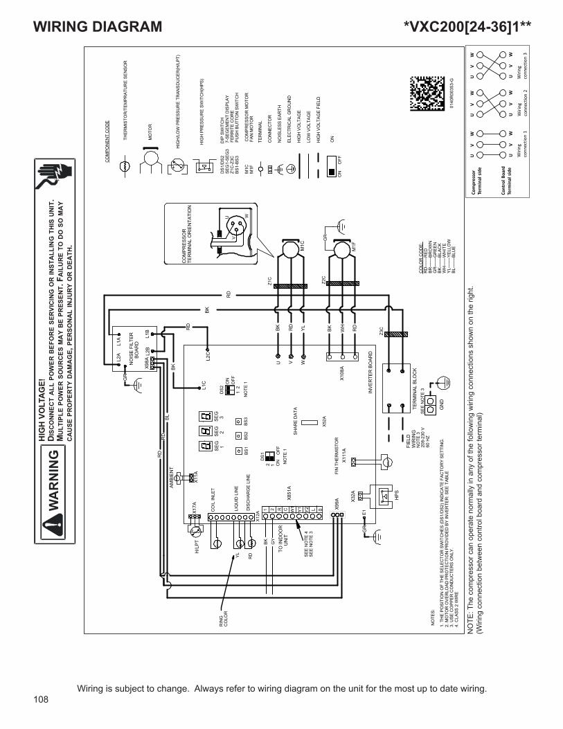
WIRING DIAGRAMH
IGH
VO
LTAG
E!D I
SCO
NN
ECT
ALL
PO
WER
BEF
OR
E SE
RVI
CIN
G O
R IN
STA
LLIN
G T
HIS
UN
IT.
MU
LTIP
LE P
OW
ER S
OU
RC
ES M
AY
BE
PRES
ENT.
FA
ILU
RE
TO D
O S
O M
AY
CA
USE
PR
OPE
RTY
DA
MA
GE,
PER
SON
AL
INJU
RY
OR
DEA
TH.
108Wiring is subject to change. Always refer to wiring diagram on the unit for the most up to date wiring.
Cont
rol B
oard
Term
inal
sid
e
Com
pres
sor
Term
inal
sid
e
UV
W
UV
W
UV
W
UV
W
UV
W
UV
W
Wiri
ng
conn
ectio
n 1
Wiri
ng
conn
ectio
n 2
Wiri
ng
conn
ectio
n 3
NO
TE: T
he c
ompr
esso
r can
ope
rate
nor
mal
ly in
any
of t
he fo
llow
ing
wiri
ng c
onne
ctio
ns s
how
n on
the
right
.(W
iring
con
nect
ion
betw
een
cont
rol b
oard
and
com
pres
sor t
erm
inal
)
*VXC200[24-36]1**
1. T
HE
POSI
TIO
N O
F TH
E SE
LEC
TOR
SW
ITC
HES
(DS1
/DS2
) IN
DIC
ATE
FAC
TOR
Y SE
TTIN
G.
2. M
OTO
R O
VER
LOAD
PR
OTE
CTI
ON
PR
OVI
DED
BY
INVE
RTE
R: S
EE T
ABLE
3. U
SE C
OPP
ER C
ON
DU
CTE
RS
ON
LY.
4. C
LASS
2 W
IRE
NO
TES:
1 2 R C W1
Y1 Y2 L 0
TO IN
DO
OR
U
NIT
X11A
AMBI
ENT
SEG
1SE
G 2
SEG
3
X17A
X851
A
X99A
HPS
RD
RD
BL
M1C
BK RD
YL
M1F
BK WH
RDRD
L2B
L1B
BK
NO
ISE
FILT
ER
BO
ARD
L2A
L1A
BK
RD
L1C
L2C
TER
MIN
AL B
LOC
KFI
ELD
WIR
ING
H/L
PT
GN
D
INVE
RTE
R B
OAR
D
CO
MPR
ESSO
RTE
RM
INAL
OR
IEN
TATI
ON
X32A
X108
A
GR
+ -
Z1C
Z2C
Z3C
X12A
CO
IL IN
LET
LIQ
UID
LIN
E
DIS
CH
ARG
E LI
NE
U V W
1O
FFO
ND
S2 2
NO
TE 1
BS1
BS2
BS3
X111
AFI
N T
HER
MIS
TOR
X52A
SHAR
E D
ATA
NO
TE 1
1O
FFO
NDS1
2
X98A
RIN
GC
OLO
R
RDYL
GY
BK
+ -
THER
MIS
TOR
/TEM
PRAT
UR
E SE
NSO
R
MO
TOR
HIG
H/L
OW
PR
ESSU
RE
TRAN
SDU
CER
(H/L
PT)
HIG
H P
RES
SUR
E SW
ITC
H(H
PS)
DS1
/DS2
D
IP S
WIT
CH
SEG
1-SE
G3
7
-SEG
EMEN
T D
ISPL
AYZ1
C-Z
3C
FER
RIT
E C
OR
EBS
1-BS
3
PU
SH B
UTT
ON
SW
ITC
H
M1C
CO
MPR
ESSO
R M
OTO
RM
1F
F
AN M
OTO
R
TER
MIN
AL
CO
NN
ECTO
R
NO
ISLE
SS E
ARTH
ELEC
TRIC
AL G
RO
UN
D
HIG
H V
OLT
AGE
LOW
VO
LTA
GE
HIG
H V
OLT
AGE
FIEL
D
CO
MPO
NEN
T C
OD
E
NO
TE 3
SEE
NO
TE 3
WUV
0140
R00
353-
G
GR
GR
E1
208-
230
V60
HZ
SEE
NO
TE 4
CO
LOR
CO
DE:
RD
------
------
-----
BR---
------
------
--G
R---
------
------
--BK
------
------
-----
WH
------
------
---YL
------
------
-----
BL---
------
------
--
RED
BRO
WN
GR
EEN
BLAC
KW
HIT
EYE
LLO
WBL
UE
SEE
NO
TE 3
ON
ON
OFF
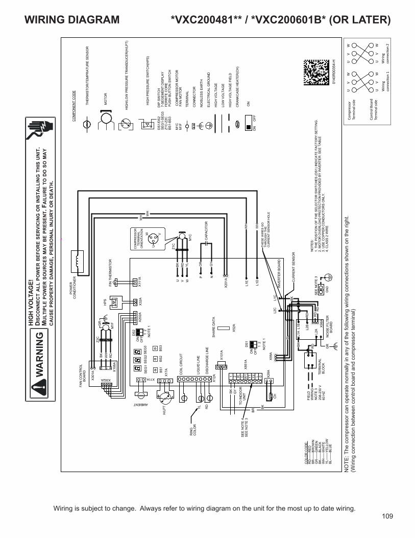
WIRING DIAGRAMH
IGH
VO
LTAG
E!D I
SCO
NN
ECT
ALL
PO
WER
BEF
OR
E SE
RVI
CIN
G O
R IN
STA
LLIN
G T
HIS
UN
IT.
MU
LTIP
LE P
OW
ER S
OU
RC
ES M
AY
BE
PRES
ENT.
FA
ILU
RE
TO D
O S
O M
AY
CA
USE
PR
OPE
RTY
DA
MA
GE,
PER
SON
AL
INJU
RY
OR
DEA
TH.
109Wiring is subject to change. Always refer to wiring diagram on the unit for the most up to date wiring.
NO
TE: T
he c
ompr
esso
r can
ope
rate
nor
mal
ly in
any
of t
he fo
llow
ing
wiri
ng c
onne
ctio
ns s
how
n on
the
right
.(W
iring
con
nect
ion
betw
een
cont
rol b
oard
and
com
pres
sor t
erm
inal
)
Cont
rol B
oard
Term
inal
side
Com
pres
sor
Term
inal
side
UV
W
UV
W
UV
W
UV
W
Wiri
ng
conn
ec�o
n 1
Wiri
ng
conn
ec�o
n 2
*VXC200481** / *VXC200601B* (OR LATER)
TO IN
DO
OR
U
NIT
SEG
1SE
G2
SEG
3
X17A
X851
A X99A
HPS
U V WM
1C
BK RD YL
M1F
BK WH
RD
WH
OR
TER
MIN
AL B
LOC
K
FIEL
DW
IRIN
G
H/L
PT
GN
DINVE
RTE
R B
OAR
D
CO
MPR
ESSO
R
TER
MIN
AL O
RIE
NTA
TIO
NX3
2A
GR
+ -Z1
C
Z2C
L1A L2
AL1B
L2B X9
8A
NO
ISE
FILT
ER
BO
ARD
L2C
L1C
X11A
AMBIENT
X111
A
FIN
TH
ERM
ISTO
R
X202
A
X301
A X108
A
X302A
P N
L1D
L1E
X201
A
GY
WH
WH W
HW
U
V
FAN
CO
NTR
OL
BOAR
D
P
OW
ER
CO
ND
ITIO
NER
BR
BK
CU
RR
ENT
SEN
SOR
X12A
CO
IL C
IRC
UIT
LIQ
UID
LIN
E
DIS
CH
ARG
E LI
NE
X101
A
NO
TE 1
1O
FFON
DS2
2
1. T
HE
POSI
TIO
N O
F TH
E SE
LEC
TOR
SW
ITC
HES
(DS1
) IN
DIC
ATE
FAC
TOR
Y SE
TTIN
G.
2. M
OTO
R O
VER
LOAD
PR
OTE
CTI
ON
PR
OVI
DED
BY
INVE
RTE
R: S
EE T
ABLE
3. U
SE C
OPP
ER C
ON
DU
CTO
RS
ON
LY.
4. C
LASS
2 W
IRE
NO
TES:
BS1
BS2
BS3
+ -
THER
MIS
TOR
/TEM
PRAT
UR
E SE
NSO
R
MO
TOR
HIG
H/L
OW
PR
ESSU
RE
TRAN
SDU
CER
(H/L
PT)
HIG
H P
RES
SUR
E SW
ITC
H(H
PS)
DS1
/DS2
D
IP S
WIT
CH
SEG
1-SE
G3
7
-SEG
EMEN
T D
ISPL
AYZ1
C-Z
2C
FER
RIT
E C
OR
EBS
1-BS
3
PU
SH B
UTT
ON
SW
ITC
H
M1C
CO
MPR
ESSO
R M
OTO
RM
1F
F
AN M
OTO
R
TER
MIN
AL
CO
NN
ECTO
R
NO
ISLE
SS E
ARTH
ELEC
TRIC
AL G
RO
UN
D
HIG
H V
OLT
AGE
LOW
VO
LTA
GE
HIG
H V
OLT
AGE
FIEL
D
CR
ANKC
ASE
HEA
TER
(CH
)
CO
MPO
NE N
T C
OD
E
CAP
ACIT
OR
X28A
CH
GR
RD
RD
BL
BK RD
BK
RD
RD
YL
RIN
GC
OLO
R
BK GY
0140
R00
354-
H
NO
TE 1
1O
FFON
DS1 2
X52A
SHAR
E D
ATA
SEE
NO
TE 3
NO
TE 3
208-
230
V60
HZ
THES
E W
IRES
GO
THR
OU
GH
TH
EC
UR
REN
T SE
NSO
R H
OLE
.
1 2 R C W1
Y1 Y2 L 0
CO
LOR
CO
DE:
RD
------
------
-----
BR---
------
------
--G
R---
------
------
--BK
------
------
-----
WH
------
------
---YL
------
------
-----
BL---
------
------
--
RED
BRO
WN
GR
EEN
BLAC
KW
HIT
EYE
LLO
WBL
UE
SEE
NO
TE 4
SEE
NO
TE 3
ON
ON
OFF
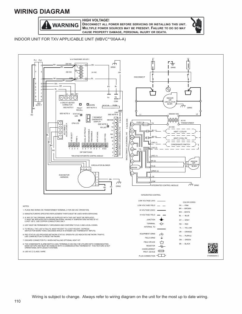
WIRING DIAGRAMHIGH VOLTAGE!DISCONNECT ALL POWER BEFORE SERVICING OR INSTALLING THIS UNIT. MULTIPLE POWER SOURCES MAY BE PRESENT. FAILURE TO DO SO MAY CAUSE PROPERTY DAMAGE, PERSONAL INJURY OR DEATH.
110Wiring is subject to change. Always refer to wiring diagram on the unit for the most up to date wiring.
�� ��+,
-��./��.����,��/
�� ����/
���
�./���,��/�����/
���� �����
�./���,��/
�./���,��/
/�
�
��
�.�/�
/
�,����
,./
�����,�
������� �
�.,� ���.�
�.���,�
��
��� �����
�
�����
-��./��.������/
�� ����/
�-��,�
/�
-
��/��,/
�
�.���.�����
,./
-���,
�
�
�
�
-���,��/, �+�/��/������ ����
�
�. ���/
�
�-��,�
-
��
�
��
���
+������,
���������,�
�/ �
��������/
�,/ ���
�/ �
�
��
�
�
���
�/
�
�
. ���/,������ �/���������
�-
�
�
��
�
�-�����/����,���� ���.� �
���
�
��
�.��� ���
���� �����
�
��
��
��
�/
�
�
�/ ���-�
�
�
. ���/
�
/�
��
������
�
�����,�
��
��
��
/!����
/� �/ �
-
�-�����,
�/ �
-
�
�
/
+,���
/��,��
�
�
���
�
/�
�����
�!����
��
��"��,���. ���/,������ �/���������
�
�/ �
��,������.���/�
/�
�/, �+�/��/�-������/����,���� ���.� �
��,�����.��/
�
�
�/
�
��/
�#�.��� ���/ �
��/�. ,�
������� ���.�
�������,���+.���
�.�����,���+.���
$� ��.�
�.�����,���������
�/��%����.��
. ���/,������ �/��
�������,�����-��
+.�������.��
�������. ��/ ,����
+.�����/ �
����/��//� �
���""""���,��
�/�""""��/, ��
���""""������
���""""��. �
���""""��/,�
/��""""�/��
��""""�.��
���""""���/���
���""""������
�/�""""��/�
����/������&
� �""""��/��
����&
%���,���/���./���� ��/, �+�/��/���/�. ,����+�/������,�����/,�.� %
�%��, �+,���/�/'������.+.���/���,���� ���,/������������������ ���/�.�. �%
�%�.+�, ���+������/.�. ,��./���,�������.���.�����.��� .����������/���,��������.����������/���,����.���./. ���,��/.,���,�. ��,������/,��/��/,�. ���+�,�������,�����(�%����������/��� �����/��� ��%
-%�� .������������/�, � �����/�� ����, ���� +�/����� %�%��, �����,�������%
�%����/��,��������,�����+,�����������/��� �������,���/��� ������/��������.����+�/���/����, ������� ����.���. ���, ����� �����/����,��. �����
�%�/�����,���������/��.���� ���/����,���%��/�� �/!�����. �.�,��� ���/���/,++.�%����������,/ ������ ����/����� ���/�%
�%��.��,/���� ����/������ �. ��,��. �����.� ,����,���.�%
�%������� �� �,���,�,/���.������,�����/�. ,����, �� ��������.�.)���.�������� .�,�. �����������������, ����������� ,�����.���,������ .�,�. �����/����,�%���.��+�,��/��.�� ���������/,�.� ,��.������,����������%
�%����� %�%����,�����./�%
�-�,���--"�
�
�
�� �� �,����.���
�,�����
�����
+���
�,�
���� �����
�+�����
��,���
���
���� �����
���� �����
/!����
��/��.����
�����,+��/�+.��
������� ,���
�/.��� ,���
�/.��*
,+�������
/��.���/
�
�
�
�
�
�
-
�
�
�
�
�
�
�
�
�
�
�
�
�
��
�
�
- � �
� �
��
��
��
/�
���� �����
���� �����
INDOOR UNIT FOR TXV APPLICABLE UNIT (MBVC**00AA-A)
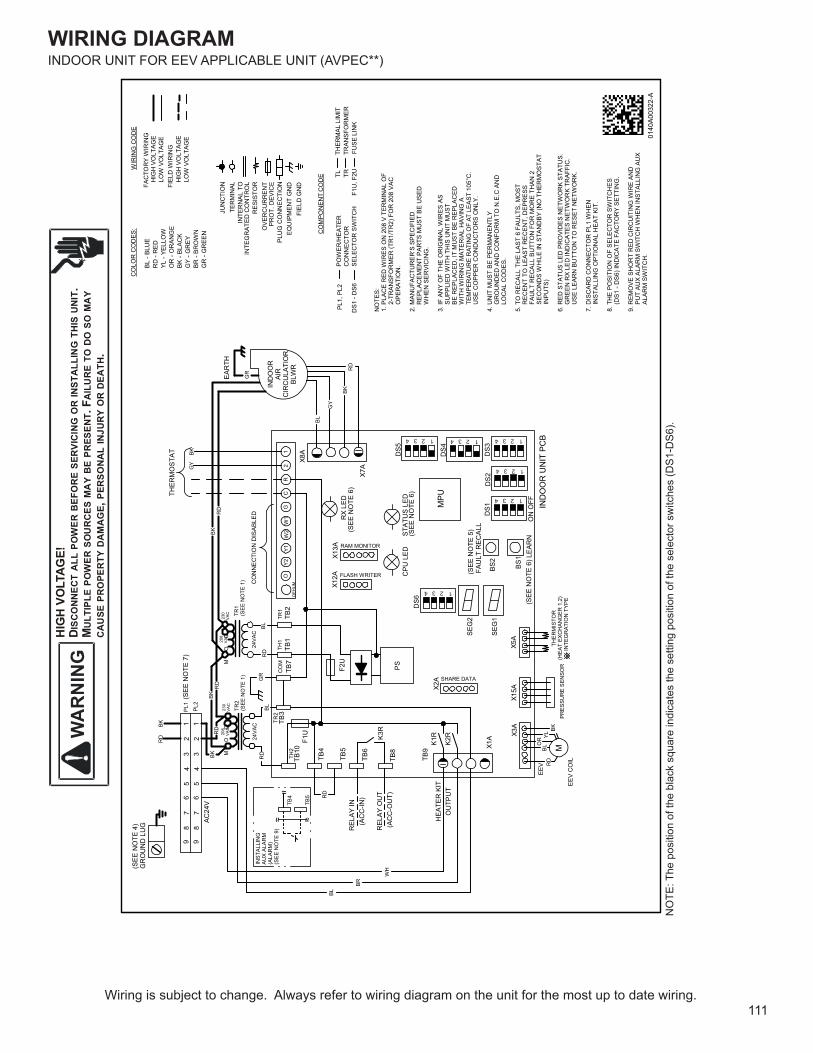
WIRING DIAGRAMH
IGH
VO
LTAG
E!D I
SCO
NN
ECT
ALL
PO
WER
BEF
OR
E SE
RVI
CIN
G O
R IN
STA
LLIN
G T
HIS
UN
IT.
MU
LTIP
LE P
OW
ER S
OU
RC
ES M
AY
BE
PRES
ENT.
FA
ILU
RE
TO D
O S
O M
AY
CA
USE
PR
OPE
RTY
DA
MA
GE,
PER
SON
AL
INJU
RY
OR
DEA
TH.
111Wiring is subject to change. Always refer to wiring diagram on the unit for the most up to date wiring.
INDOOR UNIT FOR EEV APPLICABLE UNIT (AVPEC**)
WIR
ING
CO
DE
0140
A003
22-A
POW
ER/H
EATE
RC
ON
NEC
TOR
PL1,
PL2
CO
MPO
NEN
T C
OD
E TL
F1U
, F2UTR
THER
MAL
LIM
ITTR
ANSF
OR
MER
FUSE
LIN
K
FAC
TOR
Y W
IRIN
G
HIG
H V
OLT
AGE
LO
W V
OLT
AGE
FIEL
D W
IRIN
G
HIG
H V
OLT
AGE
LO
W V
OLT
AGE
EQU
IPM
ENT
GN
D
TER
MIN
AL
PLU
G C
ON
NEC
TIO
N
JUN
CTI
ON
RES
ISTO
R
PRO
T. D
EVIC
E
INTE
GR
ATED
CO
NTR
OL
IN
TER
NAL
TO
FIEL
D G
ND
OVE
RC
UR
REN
T
BL -
BLU
ER
D -
RED
YL -
YELL
OW
OR
- O
RAN
GE
BK -
BLAC
KG
Y - G
REY
BR -
BRO
WN
GR
- G
REE
N
CO
L OR
CO
DES
:
NO
TES:
1. P
LAC
E R
ED W
IRES
ON
208
V T
ERM
INAL
OF
2-T
RAN
SFO
RM
ER (T
R1/
TR2)
FO
R 2
08 V
ACO
PER
ATIO
N.
2. M
ANU
FAC
TUR
ER’S
SPE
CIF
IED
REP
LAC
EMEN
T PA
RTS
MU
ST B
E U
SED
WH
EN S
ERVI
CIN
G.
3. IF
AN
Y O
F TH
E O
RIG
INAL
WIR
ES A
S S
UPP
LIED
WIT
H T
HIS
UN
IT M
UST
BE
REP
LAC
ED, I
T M
UST
BE
REP
LAC
EDW
ITH
WIR
ING
MAT
ERIA
L H
AVIN
G A
USE
CO
PPER
CO
ND
UC
TOR
S O
NLY
.
4. U
NIT
MU
ST B
E PE
RM
ANEN
TLY
GR
OU
ND
ED A
ND
CO
NFO
RM
TO
N.E
.C A
ND
LO
CAL
CO
DES
.
5. T
O R
ECAL
L TH
E LA
ST
6 FA
ULT
S, M
OST
REC
ENT
TO L
EAS
T R
ECEN
T, D
EPR
ESS
FAU
LT R
ECAL
L BU
TTO
N F
OR
MO
RE
THAN
2SE
CO
ND
S W
HIL
E IN
STA
ND
BY (N
O T
HER
MO
STAT
INPU
TS)
6. R
ED S
TATU
S LE
D P
RO
VID
ES N
ETW
OR
K ST
ATU
S. G
REE
N R
X LE
D IN
DIC
ATES
NET
WO
RK
TRAF
FIC
.U
SE L
EAR
N B
UTT
ON
TO
RES
ET N
ETW
OR
K.
7. D
ISC
ARD
CO
NN
ECTO
R P
L1 W
HEN
INST
ALLI
NG
OPT
ION
AL H
EAT
KIT.
8. T
HE
POSI
TIO
N O
F SE
LEC
TOR
SW
ITC
HES
(DS1
- D
S6) I
ND
ICAT
E FA
CTO
RY
SETT
ING
.
9. R
EMO
VE S
HO
RT
RED
CIR
CU
ITIN
G W
IRE
AND
PUT
AUX
ALAR
M S
WIT
CH
WH
EN IN
STAL
LIN
G A
UX
ALAR
M S
WIT
CH
.
DS6
X1A X3
AX1
5A
BS2
X5A
X2A
BS1
SEG
2
SEG
1D
S1D
S2D
S3
DS4DS5
X7A
X12A
X13A
RX
LED
X8A
IND
OO
R U
NIT
PC
BTH
ERM
ISTO
R(H
EAT
EXC
HAN
GER
1,2
)
IN
TEG
RAT
ION
TYP
E
MPU
CPU
LED
STAT
US
LED
FAU
LT R
ECAL
L
PRES
SUR
E SE
NSO
REE
V C
OIL
EEV
M
IND
OO
RAI
RC
IRC
ULA
TIO
RBL
WR
EAR
TH
K1R
TB9
K3R
TB6
TB8
K2R
HEA
TER
KIT
OU
TPU
T
LEAR
N
PSF2U
TB5
TB10
TB4
TB3
TB1
TB7
TB2
F1U
REL
AY IN
(AC
C-O
UT)
REL
AY O
UT
(AC
C-IN
)
AC24
V
TH1
CO
MY2
OTR
1W
2Y1
CG
W1
R2
1
89
67
34
51
2
DEH
UM
BKR
D
RD
BKR
D
BK
GY
BL
WH
BR
BL
RD
BK RD
BL
SHARE DATA
FLASH WRITER
RAM MONITOR
ON
OFF
BKR
DYL
OR
BL
BLR
D
PL1
(SEE
NO
TE 7
)
RD
BK
SELE
CTO
R S
WIT
CH
DS1
- D
S6
GR
GR
GR
OU
ND
LU
G
TH2
TR2
THER
MO
STAT
CO
NN
ECTI
ON
DIS
ABLE
D
BKG
Y
(SEE
NO
TE 6
)
(SEE
NO
TE 5
)(SEE
NO
TE 6
)
(SEE
NO
TE 6
)
(SEE
NO
TE 4
) 89
67
34
51
2PL
2
24VA
C
TB5
TB4
INST
ALLI
NG
AUX
ALAR
M(A
LAR
M)
(SEE
NO
TE 9
)
RD
~~ ~~
~~24
VAC
MO
CM
OC
208
VAC
230
VAC
208
VAC
230
VAC
TR2
(SEE
NO
TE 1
)TR
1(S
EE N
OTE
1)
4 3 2 1
4 3 2 1
4 3 2 14 3 2 14 3 2 1
4 3 2 1TE
MPE
RAT
UR
E R
ATIN
G O
F AT
LEA
ST 1
05°C
.
NO
TE: T
he p
ositi
on o
f the
bla
ck s
quar
e in
dica
tes
the
setti
ng p
ositi
on o
f the
sel
ecto
r sw
itche
s (D
S1-D
S6).
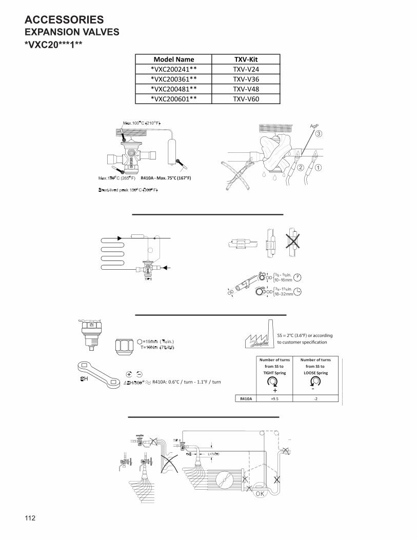
ACCESSORIES
112
EXPANSION VALVES*VXC20***1**
SS = 2°C (3.6°F) or according cation
Number of turns
from SS to
tight spring
Number of turns
from SS to
loose spring
R22 +7.25 –4.25
R410A +9.5 –2
R410A: 0.6°C / turn - 1.1°F / turn
R410A - Max. 75°C (167°F)
Number of turns Number of turnsfrom SS to from SS to
TIGHT Spring LOOSE Spring
R410A +9.5 -2
-
+
Model Name TXV-Kit*VXC200241** TXV-V24*VXC200361** TXV-V36*VXC200481** TXV-V48*VXC200601** TXV-V60
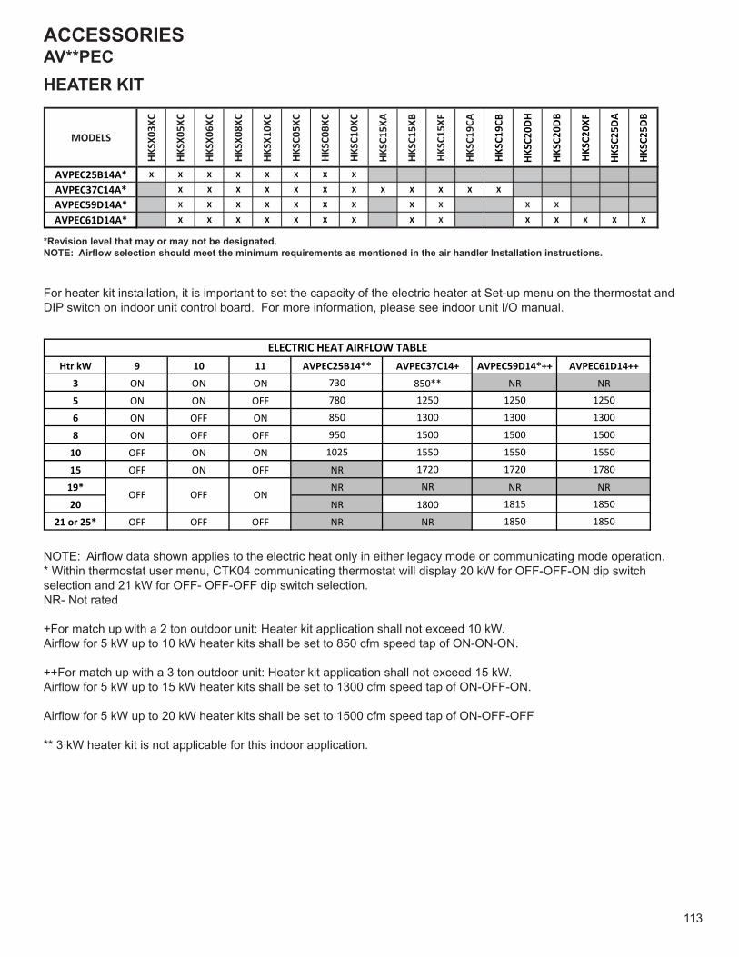
ACCESSORIES
113
AV**PECHEATER KIT
MODELSHK
SX03
XC
HKSX
05XC
HKSX
06XC
HKSX
08XC
HKSX
10XC
HKSC
05XC
HKSC
08XC
HKSC
10XC
HKSC
15XA
HKSC
15XB
HKSC
15XF
HKSC
19CA
HKSC
19CB
HKSC
20DH
HKSC
20DB
HKSC
20XF
HKSC
25DA
HKSC
25DB
AVPEC25B14A* X X X X X X X X
AVPEC37C14A* X X X X X X X X X X X X
AVPEC59D14A* X X X X X X X X X X X
AVPEC61D14A* X X X X X X X X X X X X X X
*Revision level that may or may not be designated.NOTE: Airflow selection should meet the minimum requirements as mentioned in the air handler Installation instructions.
For heater kit installation, it is important to set the capacity of the electric heater at Set-up menu on the thermostat and DIP switch on indoor unit control board. For more information, please see indoor unit I/O manual.
NOTE: Airflow data shown applies to the electric heat only in either legacy mode or communicating mode operation. * Within thermostat user menu, CTK04 communicating thermostat will display 20 kW for OFF-OFF-ON dip switch selection and 21 kW for OFF- OFF-OFF dip switch selection. NR- Not rated
+For match up with a 2 ton outdoor unit: Heater kit application shall not exceed 10 kW. Airflow for 5 kW up to 10 kW heater kits shall be set to 850 cfm speed tap of ON-ON-ON. ++For match up with a 3 ton outdoor unit: Heater kit application shall not exceed 15 kW. Airflow for 5 kW up to 15 kW heater kits shall be set to 1300 cfm speed tap of ON-OFF-ON. Airflow for 5 kW up to 20 kW heater kits shall be set to 1500 cfm speed tap of ON-OFF-OFF ** 3 kW heater kit is not applicable for this indoor application.
Htr kW 9 10 11 AVPEC25B14** AVPEC37C14+ AVPEC59D14*++ AVPEC61D14++3 ON ON ON 730 850** NR NR5 ON ON OFF 780 1250 1250 12506 ON OFF ON 850 1300 1300 13008 ON OFF OFF 950 1500 1500 1500
10 OFF ON ON 1025 1550 1550 155015 OFF ON OFF NR 1720 1720 1780
19* NR NR NR NR20 NR 1800 1815 1850
21 or 25* OFF OFF OFF NR NR 1850 1850
ON
ELECTRIC HEAT AIRFLOW TABLE
OFF OFF
114
CUSTOMER FEEDBACKWe are very interested in all product comments.Please fill out the feedback form on one of the following links:Goodman® Brand Products: (http://www.goodmanmfg.com/about/contact-us).Amana® Brand Products: (http://www.amana-hac.com/about-us/contact-us).You can also scan the QR code on the right for the product brandyou purchased to be directed to the feedback page. GOODMAN® BRAND AMANA® BRAND
is a registered trademark of Maytag Corporation or its related companies and is used under license.All rights reserved.
Copyright © 2015-2017, 2020-2021 Goodman Manufacturing Company, L.P.
®