Design, construction, and characterization of a six-electrode ...
Upload
independentCategory
view
0download
0
This article appeared in a journal published by Elsevier. The attachedcopy is furnished to the author for internal non-commercial researchand education use, including for instruction at the authors institution
and sharing with colleagues.
Other uses, including reproduction and distribution, or selling orlicensing copies, or posting to personal, institutional or third party
websites are prohibited.
In most cases authors are permitted to post their version of thearticle (e.g. in Word or Tex form) to their personal website orinstitutional repository. Authors requiring further information
regarding Elsevier’s archiving and manuscript policies areencouraged to visit:
http://www.elsevier.com/copyright
Author's personal copy
Sensing electrochemical activity in polymer-coated metals during the early stagesof coating degradation by means of the scanning vibrating electrode technique
J.J. Santana 1, J. González-Guzmán, J. Izquierdo, S. González, R.M. Souto ⇑Department of Physical Chemistry, University of La Laguna, E-38205 La Laguna, Tenerife, Canary Islands, Spain
a r t i c l e i n f o
Article history:Received 27 May 2010Accepted 7 August 2010Available online 11 August 2010
Keywords:A. Organic coatingsB. Scanning vibrating electrode techniqueC. Anodic dissolutionC. CorrosionC. Oxygen reduction
a b s t r a c t
Application of scanning vibrating electrode technique (SVET) for corrosion studies of organic coatings onreactive metals is presented. SVET was used to monitor the electrochemical processes at painted steelimmersed in either 10 mM Na2SO4 or 10 mM NaCl aqueous solutions. The coated samples were investi-gated after a scratch was operated through the polymer matrix down to the metal–substrate surface inorder to simulate a defect across the coating. SVET imaging probes that the electrochemical behaviour ofthe system is different depending on the electrolyte employed. Enhanced coating delamination originat-ing from the defect is observed when chloride ions are present in the environment.
� 2010 Elsevier Ltd. All rights reserved.
1. Introduction
The testing of metal–coating systems for efficacy and screeningof trial products is generally carried out by atmospheric exposureand accelerated salt spray laboratory tests. But these methods pro-vide very little information about the complex interactions withinthe system comprising metal, polymer film and corrosion medium.Therefore, electrochemical methods, particularly electrochemicalimpedance spectroscopy (EIS) have come to be widely employedin monitoring the physicochemical changes occurring during theexposure of a metal–coating system to a given corrosive environ-ment, and recently a standard testing procedure based on EIS hasbeen implemented [1]. A recent review on uses of EIS in the fieldof corrosion can be found in Ref. [2]. In this way, the EIS techniquehave probed to be very useful for ranking the corrosion resistanceof different metal–coating systems, and though difficulties are of-ten met during attempts to correlate accelerated laboratory testswith the results of conventional atmospheric exposures, this tech-nique has shown to be a very effective tool for the detection ofpores or defects in the coating [2,3] at significantly earlier timesthan non-electrochemical tests. Indeed, relevant informationregarding both the electrochemical behaviour of the metal–coatingsystem and the extent of the unprotected metallic areas can be ex-tracted from the analysis of the impedance spectra [3].
For corrosion protection to be optimized, the localized degrada-tion mechanisms operating in coated metals should be fully under-stood. Only then the most effective metal–coating combination canbe chosen for a particular application and the exact causes of dam-age be ascertained. Though conventional electrochemical tech-niques, including electrochemical impedance spectroscopy,provide valuable information about these processes, they are inte-gral methods that average the behaviour of the sample and theylack spatial resolution. As a consequence, the current understand-ing of how coatings protect and the mechanisms of corrosionbreakdown are not yet completely known.
To characterize localized processes occurring in the degradationof coated metals, during the past two decades, several local electro-chemical measurement techniques have been introduced to theinvestigation of these processes because they provide spatially re-solved information typically at microscopic and submicroscopicranges. Among them, the use of the Scanning Kelvin Probe (SKP)has produced the biggest number of publications in the field untilnow, since this technique is suited to monitor buried interfaces,such as those originating from defects and cut edges at coated met-als [3–6]. But this technique do not actually operate in situ, that is,in the electrolytic environment responsible for the corrosive at-tack, with the outcome that the real electrical state of the underly-ing metal substrate which develops in the aggressive environmentcannot be established. Thus, there is need for other microelectro-chemical techniques to be employed, including scanning referenceelectrode technique (SRET) [7–9], scanning vibrating electrodetechnique (SVET) [6,8,9], local electrochemical impedance spec-troscopy (LEIS) [10,11], and scanning electrochemical microscopy(SECM) [12–14]. Scanning electrochemical microscopy consists of
0010-938X/$ - see front matter � 2010 Elsevier Ltd. All rights reserved.doi:10.1016/j.corsci.2010.08.010
⇑ Corresponding author. Tel.: +34 922 318067; fax: +34 922 318002.E-mail address: [email protected] (R.M. Souto).
1 On leave from the Department of Process Engineering, University of Las Palmas deGran Canaria, Campus Universitario de Tafira, E-35017 Las Palmas de Gran Canaria,Canary Islands, Spain.
Corrosion Science 52 (2010) 3924–3931
Contents lists available at ScienceDirect
Corrosion Science
journal homepage: www.elsevier .com/locate /corsc i
Author's personal copy
measuring a faradaic current at the ultramicroelectrode tip, whichresults from the redox transformation of an oxidizable/reduciblespecies used as mediator in the solution or originating from thecorrosion process at the surface [15]. The technique thus suppliesboth topographic and electrochemical reactivity informationwhereas the tip scans a substrate, and has been successfully em-ployed to investigate intact as well as defective coatings. In the firstcase, local swelling could be detected for the first time at earlyexposures [16–20], whereas in the second, the release of metal ionsat the microanodes and the consumption of oxygen at the micro-cathodes could be monitored [21–23]. Localized electrochemicalimpedance spectroscopy also utilizes a polarizable microelectrode,but it can exclusively be employed to characterize defective coat-ings by measuring the local impedance at the exposed metal–elec-trolyte interface [10,11], and it has no chemical selectivity.
An alternative approach is employed in the remaining twomicroelectrochemical techniques, which consist basically of scan-ning a reference microelectrode over the immersed specimen,either in static mode (scanning reference electrode) or in a vibrat-ing mode (scanning vibrating electrode) and thus allow for poten-tial distributions in the electrolyte around the defect to bedetected. Among the two, the highest sensitivity is exhibited bySVET because it detects local gradients instead of absolute poten-tial distributions in the electrolytic phase [9]. Furthermore, SVETcan monitor ionic fluxes arising from the defect provided the con-ductivity of the electrolyte is known [6], which is especially usefulto monitor the homogeneous interaction of the chemical speciesgenerated at the locally separated anodic and cathodic areas onthe surface in corrosion reactions (cf. Fig. 1). And the SVET datacan be calibrated and converted into a measurement of metal lossusing Faraday’s law [24]. Thus, the SVET has become a very power-ful technique for probing a variety processes in metal–coating sys-tems, including delamination processes from cut edges andscratches, as well as self-healing processes at defects [25–36]. Acommon observation from these previous works is that the currentfluxes related to the anodic and cathodic half-cell reactions cannotbe balanced, thus suggesting that most of the cathodic activity oc-curs under coatings and could not be detected by SVET. It has al-ready been established by other researchers on the basis of SKPmeasurements, that the cathodic reaction progresses below thecoated film. Yet, the transport of oxygen (an uncharged species)to fuel the cathodic half reaction could not be monitored so far. Sig-nificant evidence on this direction is provided by the work con-ducted by Khobaib et al. [29] on thin sol–gel based coatingsystems, for which they monitored corrosion activity under thecoatings using SVET. Nevertheless, a similar observation for thickerfilms such as those formed by polymeric organic coatings have notyet been attained.
In the course of a research project conducted at our laboratory de-voted to establish correlations between accelerated laboratory tests
based on the application of electrochemical techniques and atmo-spheric exposure tests employed in industry, a variety of corrosionprotection paint systems have been investigated using EIS. Theinvestigated paint systems covered several polymeric matrixes[37–40], as well as the possible addition of different pigments to agiven polymer composition [41–43]. During that work, a paint for-mulation exhibiting a greater porosity in the submicron range com-pared to those previously considered was found, though allowed tocure at room temperature for sufficiently long periods. EIS spectra ofthe intact coating immersed in a chloride-containing aqueous elec-trolyte shown in Fig. 2 do not exhibit a purely capacitive behaviourin the high frequency range at any times. Conversely, they exhibitedtwo time constants even at early exposures, and could be satisfacto-rily modeled by considering a defective-barrier coating film [44,45].On the other hand, SECM imaging of the coated sample does not de-tect any electrochemical activity in the micrometric and submicro-metric ranges when scanned in the feedback mode [46]. That is, nodetectable area of the metal is directly exposed to the electrolyteas to produce electrochemically-active localized sites. Therefore,we considered this system to be an interesting candidate for inves-tigation with the SVET.
Herein we report on the electrochemical performance of a com-mercial paint system for the corrosion protection of mild steel pan-els as derived from experiments employing the scanning vibratingelectrode technique. The choice of this technique has been deter-mined by the previous finding that an epoxy-polyamine resin con-taining glass flakes applied on steel originates a highly porouslayer, compared to the polymer matrix without pigments, as de-duced from electrochemical impedance spectroscopy measure-ments [43]. The special nature of this coating layer may affectthe local distribution of the corrosion reactions in and around ascratch produced through the polymer film until the underlyingmetal, which should be monitored in the micrometric range. Spe-cifically, we report SVET images of complex electrochemical behav-iour that occurs on metallic substrates protected by organiccoatings in the vicinity of a defect when exposed to different elec-trolyte solutions.
2. Experimental
2.1. Materials and substrate preparation
A commercial two-component epoxy-polyamine primer con-taining glass flakes as pigment (SIGMACOVER TCP GLASSFLAKE,
Mn+(aq)
O2(aq)
OH-(aq)
M(OH)n(s)
Metal e-
Electrolyte
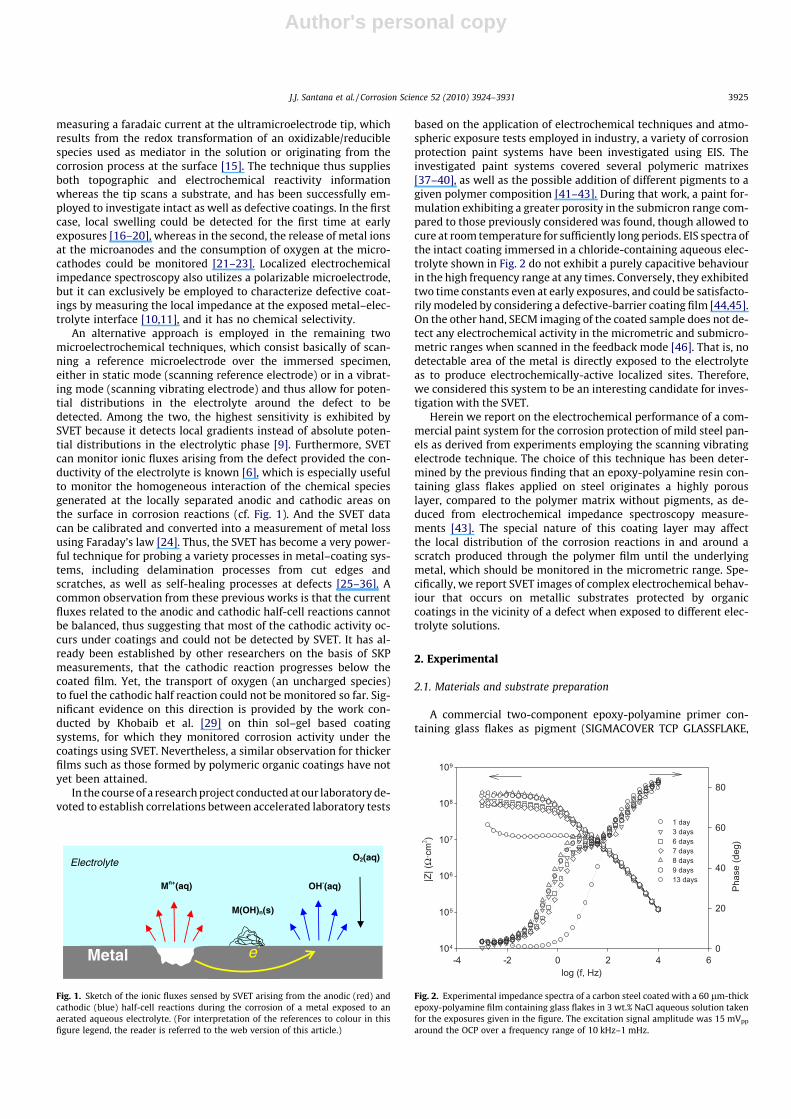
Fig. 1. Sketch of the ionic fluxes sensed by SVET arising from the anodic (red) andcathodic (blue) half-cell reactions during the corrosion of a metal exposed to anaerated aqueous electrolyte. (For interpretation of the references to colour in thisfigure legend, the reader is referred to the web version of this article.)
log (f, Hz)-4 -2 0 2 4 6
|Z| (
Ω·c
m2 )
104
105
106
107
108
109
Pha
se (d
eg)
0
20
40
60
80
1 day3 days6 days7 days8 days9 days13 days
Fig. 2. Experimental impedance spectra of a carbon steel coated with a 60 lm-thickepoxy-polyamine film containing glass flakes in 3 wt.% NaCl aqueous solution takenfor the exposures given in the figure. The excitation signal amplitude was 15 mVpp
around the OCP over a frequency range of 10 kHz–1 mHz.
J.J. Santana et al. / Corrosion Science 52 (2010) 3924–3931 3925
Author's personal copy
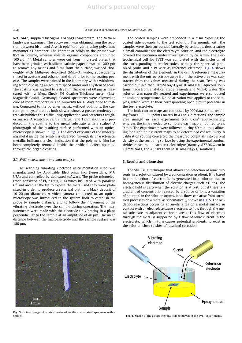
Ref. 7447) supplied by Sigma Coatings (Amsterdam, The Nether-lands) was examined. The epoxy resin was obtained from the reac-tion between bisphenol A with epichlorohydrin, using polyaminemonomer as hardener. The content of solids in the primer was85% in volume, whereas volatile organic compounds amounted105 g dm�3. Metal samples were cut from mild steel plates thathave been grinded with silicon carbide paper down to 1200 gritto remove any oxides and films from the surface, washed thor-oughly with Millipore deionised (Milli-Q) water, subsequentlyrinsed in acetone and ethanol, and dried prior to the coating pro-cess. The samples were painted in the laboratory with a withdraw-ing technique using an accurate speed motor and a system of gears.The coating was applied to a dry film thickness of 60 lm as mea-sured with a Mega-Check FN Coating-Thickness-meter (List-Magnetik GmbH, Germany). Coated specimens were allowed tocure at room temperature and humidity for 10 days prior to test-ing. Compared to the polymer matrix without additions, the cur-rent paint system cures both slower, shows a greater tendency totrap air bubbles thus difficulting application, and presents a rough-er surface. A scratch of ca. 1 cm length and 1 mm width was pro-duced in the coating to the metal substrate with a scalpel. Aphotograph of the resulting surface performed with an opticalmicroscope is shown in Fig. 3. The direct exposure of the underly-ing metal inside the scratch is observed through its characteristicmetallic brilliance, a clear indication that the polymeric film hasbeen completely removed inside the artificial defect operatedthrough the organic coating.
2.2. SVET measurement and data analysis
The scanning vibrating electrode instrumentation used wasmanufactured by Applicable Electronics Inc. (Forestdale, MA,USA) and controlled by dedicated software. The probe microelec-trode consisted of Pt/Ir (80%/20%) wires insulated with paraleneC� and arced at the tip to expose the metal, and they were plati-nized in order to produce a spherical platinum black deposit of10–20 lm diameter. A video camera connected to an opticalmicroscope was introduced in the system both to establish theprobe to sample distance, and to follow the movement of thevibrating electrode over the sample during operation. The mea-surements were made with the electrode tip vibrating in a planeperpendicular to the sample at an amplitude of 40 lm. The meandistance between the microelectrode and the sample surface was150 lm.
The coated samples were embedded in a resin exposing thecoated side upwards to the test solution. The mounts with thesamples were then surrounded laterally by sellotape, thus creatinga small container for the electrolyte solution, and the electrolytecovered the specimen under investigation by ca. 4 mm. The elec-trochemical cell for SVET was completed with the inclusion ofthe corresponding microelectrodes, namely the spherical plati-nized probe and a Pt wire as reference electrode. Fig. 4 showsthe distribution of the elements in the cell. A reference measure-ment with the microelectrode away from the active area was sub-tracted from the values measured during the scan. Testing wascarried out in either 10 mM Na2SO4 or 10 mM NaCl aqueous solu-tions made from analytical grade reagents and Milli-Q water. Thesolution was naturally aerated and experiments were conductedat ambient temperature. No polarization was applied to the sam-ples, which were at their corresponding open circuit potential inthe test electrolyte.
The ionic current maps are composed by 900 data points, result-ing from a 30 � 30 points matrix in X and Y directions. The samplearea imaged in each experiment was 6 cm2 approximately,whereas the time needed to complete each map amounted to ca.9 min. The experiments were followed during 80 min, thus allow-ing for eight ionic current maps to be determined consecutively. Acalibration routine converted the measured potentials into currentdensity at the corroding surface by using the experimental conduc-tivities measured in each test electrolyte (namely, 877.96 X cm in10 mM NaCl, and 483.09 X cm in 10 mM Na2SO4 solutions).
3. Results and discussion
The SVET is a technique that allows the detection of ionic cur-rents in a solution caused by a concentration gradient. It is basedin the detection of electric fields generated in a solution due tohomogeneous distribution of electric charges such as ions. Theelectric field is zero when the solution is at rest, but if there is agradient of concentration caused by a source of ions, a variationof potential in the solution occurs. Ionic flows can arise from corro-sion processes on a metal as schematically shown in Fig. 5. The oxi-dation reactions occurring at anodic sites on a metal surface incontact with an electrolyte cause electrons to flow through the me-tal substrate to adjacent cathodic areas. This flow of electronsthrough the metal is supported by a flow of ionic current in theelectrolyte, which in turn causes potential gradients to exist inthe solution close to sites of localized corrosion.
Fig. 3. Optical image of scratch produced in the coated steel specimen with ascalpel. Fig. 4. Sketch of the electrochemical cell employed in the SVET experiments.
3926 J.J. Santana et al. / Corrosion Science 52 (2010) 3924–3931
Author's personal copy
3.1. Imaging a scratch in epoxy-polyamine coated carbon steel duringimmersion in 10 mM Na2SO4
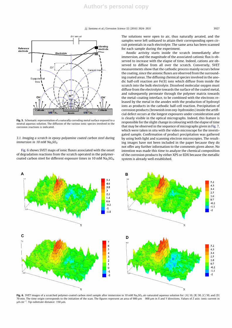
Fig. 6 shows SVET maps of ionic fluxes associated with the onsetof degradation reactions from the scratch operated in the polymer-coated carbon steel for different exposure times in 10 mM Na2SO4.
The solutions were open to air, thus naturally aerated, and thesamples were left unbiased to attain their corresponding open cir-cuit potentials in each electrolyte. The same area has been scannedfor each sample during the experiment.
Anodic activity starts inside the scratch immediately afterimmersion, and the magnitude of the associated cationic flux is ob-served to increase with the elapse of time. Indeed, cations are ob-served to diffuse from all over the scratch. Conversely, SVETmeasurements show that the cathodic process mainly occurs belowthe coating, since the anionic fluxes are observed from the surround-ing coated areas. The diffusing chemical species involved in the ano-dic half-cell reaction are Fe(II) ions which diffuse from inside thescratch into the bulk electrolyte. Dissolved molecular oxygen mustdiffuse from the electrolyte towards the surface of the coated metal,and subsequently permeate through the polymer matrix towardsthe metal–coating interface, to be combined with the electrons re-leased by the metal in the anodes with the production of hydroxylions as products in the cathodic half-cell reaction. Precipitation ofcorrosion products (brownish iron oxy-hydroxides) inside the artifi-cial defect occurs at the longest exposures under consideration andis clearly visible in the optical micrographs. Indeed, this feature isresponsible for the slight change in colouring with the elapse of timethat may be observed in the sequence of micrographs given in Fig. 7,which were taken in situ with the video microscope for the investi-gated sample. Confirmation of product precipitation was gatheredby using both light and scanning electron microscopies. The result-ing images have not been included in the paper because they donot offer any further information to the comments given above. Nointention was made this time to analyze the chemical compositionof the corrosion products by either XPS or EDX because the metallicsystem is already well established.
Fig. 5. Schematic representation of a naturally corroding metal surface exposed to aneutral aqueous solution. The diffusion of the various ionic species involved in thecorrosion reactions is indicated.
Fig. 6. SVET images of a scratched polymer-coated carbon steel sample after immersion in 10 mM Na2SO4 air-saturated aqueous solution for: (A) 10, (B) 30, (C) 50, and (D)70 min. The time origin corresponds to the initiation of the scan. The figures represent an area of 900 lm � 900 lm in X and Y directions. Values of Z axis: ionic current inlA cm�1. Tip-substrate distance: 150 lm.
J.J. Santana et al. / Corrosion Science 52 (2010) 3924–3931 3927
Author's personal copy
In summary, when the defective sample was imaged with theSVET during its immersion in 0.1 M Na2SO4 air-saturated aque-ous solution, all the information from the maps is exclusivelyfrom ionic currents due to the diffusion of charged soluble spe-cies. Collection efficiency is thus hindered when product precip-itation occurs [47], though this effect is regarded to be rather
small in this case as supported by the optical images shown inFig. 7. On the other hand, SVET measurements support thatthe anodic process is distributed over the exposed metal insidethe scratch, whereas the corresponding cathodic reactions areobserved to occur below the coating in zones surrounding thedefect.
Fig. 7. Optical micrograph images of the scratched polymer-coated carbon steel sample considered in Fig. 6. They show the time evolution of the scratch during immersion in10 mM Na2SO4 air-saturated aqueous solution.
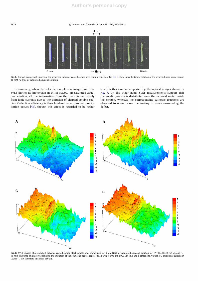
Fig. 8. SVET images of a scratched polymer-coated carbon steel sample after immersion in 10 mM NaCl air-saturated aqueous solution for: (A) 10, (B) 30, (C) 50, and (D)70 min. The time origin corresponds to the initiation of the scan. The figures represent an area of 900 lm x 900 lm in X and Y directions. Values of Z axis: ionic current inlA cm�1. Tip-substrate distance: 150 lm.
3928 J.J. Santana et al. / Corrosion Science 52 (2010) 3924–3931
Author's personal copy
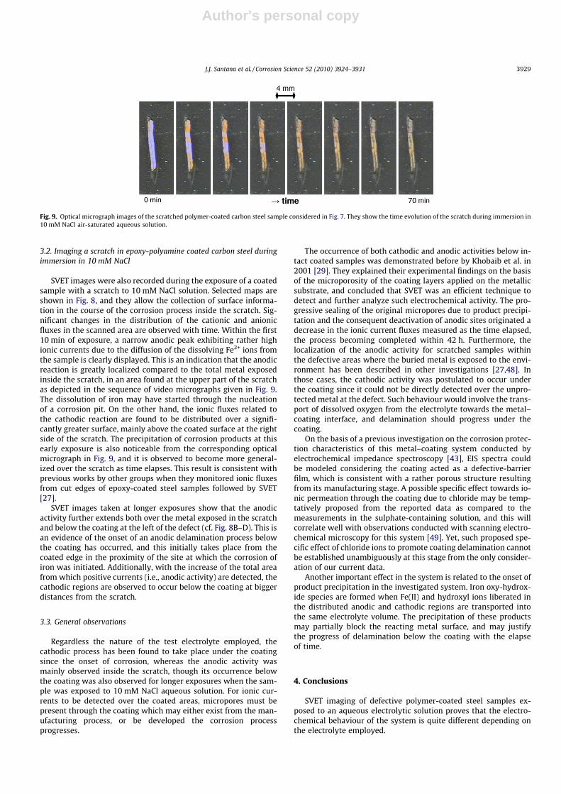
3.2. Imaging a scratch in epoxy-polyamine coated carbon steel duringimmersion in 10 mM NaCl
SVET images were also recorded during the exposure of a coatedsample with a scratch to 10 mM NaCl solution. Selected maps areshown in Fig. 8, and they allow the collection of surface informa-tion in the course of the corrosion process inside the scratch. Sig-nificant changes in the distribution of the cationic and anionicfluxes in the scanned area are observed with time. Within the first10 min of exposure, a narrow anodic peak exhibiting rather highionic currents due to the diffusion of the dissolving Fe2+ ions fromthe sample is clearly displayed. This is an indication that the anodicreaction is greatly localized compared to the total metal exposedinside the scratch, in an area found at the upper part of the scratchas depicted in the sequence of video micrographs given in Fig. 9.The dissolution of iron may have started through the nucleationof a corrosion pit. On the other hand, the ionic fluxes related tothe cathodic reaction are found to be distributed over a signifi-cantly greater surface, mainly above the coated surface at the rightside of the scratch. The precipitation of corrosion products at thisearly exposure is also noticeable from the corresponding opticalmicrograph in Fig. 9, and it is observed to become more general-ized over the scratch as time elapses. This result is consistent withprevious works by other groups when they monitored ionic fluxesfrom cut edges of epoxy-coated steel samples followed by SVET[27].
SVET images taken at longer exposures show that the anodicactivity further extends both over the metal exposed in the scratchand below the coating at the left of the defect (cf. Fig. 8B–D). This isan evidence of the onset of an anodic delamination process belowthe coating has occurred, and this initially takes place from thecoated edge in the proximity of the site at which the corrosion ofiron was initiated. Additionally, with the increase of the total areafrom which positive currents (i.e., anodic activity) are detected, thecathodic regions are observed to occur below the coating at biggerdistances from the scratch.
3.3. General observations
Regardless the nature of the test electrolyte employed, thecathodic process has been found to take place under the coatingsince the onset of corrosion, whereas the anodic activity wasmainly observed inside the scratch, though its occurrence belowthe coating was also observed for longer exposures when the sam-ple was exposed to 10 mM NaCl aqueous solution. For ionic cur-rents to be detected over the coated areas, micropores must bepresent through the coating which may either exist from the man-ufacturing process, or be developed the corrosion processprogresses.
The occurrence of both cathodic and anodic activities below in-tact coated samples was demonstrated before by Khobaib et al. in2001 [29]. They explained their experimental findings on the basisof the microporosity of the coating layers applied on the metallicsubstrate, and concluded that SVET was an efficient technique todetect and further analyze such electrochemical activity. The pro-gressive sealing of the original micropores due to product precipi-tation and the consequent deactivation of anodic sites originated adecrease in the ionic current fluxes measured as the time elapsed,the process becoming completed within 42 h. Furthermore, thelocalization of the anodic activity for scratched samples withinthe defective areas where the buried metal is exposed to the envi-ronment has been described in other investigations [27,48]. Inthose cases, the cathodic activity was postulated to occur underthe coating since it could not be directly detected over the unpro-tected metal at the defect. Such behaviour would involve the trans-port of dissolved oxygen from the electrolyte towards the metal–coating interface, and delamination should progress under thecoating.
On the basis of a previous investigation on the corrosion protec-tion characteristics of this metal–coating system conducted byelectrochemical impedance spectroscopy [43], EIS spectra couldbe modeled considering the coating acted as a defective-barrierfilm, which is consistent with a rather porous structure resultingfrom its manufacturing stage. A possible specific effect towards io-nic permeation through the coating due to chloride may be temp-tatively proposed from the reported data as compared to themeasurements in the sulphate-containing solution, and this willcorrelate well with observations conducted with scanning electro-chemical microscopy for this system [49]. Yet, such proposed spe-cific effect of chloride ions to promote coating delamination cannotbe established unambiguously at this stage from the only consider-ation of our current data.
Another important effect in the system is related to the onset ofproduct precipitation in the investigated system. Iron oxy-hydrox-ide species are formed when Fe(II) and hydroxyl ions liberated inthe distributed anodic and cathodic regions are transported intothe same electrolyte volume. The precipitation of these productsmay partially block the reacting metal surface, and may justifythe progress of delamination below the coating with the elapseof time.
4. Conclusions
SVET imaging of defective polymer-coated steel samples ex-posed to an aqueous electrolytic solution proves that the electro-chemical behaviour of the system is quite different depending onthe electrolyte employed.
Fig. 9. Optical micrograph images of the scratched polymer-coated carbon steel sample considered in Fig. 7. They show the time evolution of the scratch during immersion in10 mM NaCl air-saturated aqueous solution.
J.J. Santana et al. / Corrosion Science 52 (2010) 3924–3931 3929
Author's personal copy
The anodic activity, related to the electrodissolution of theunderlying metal, occurs almost exclusively within the scratch inthe sulphate-containing solution. Conversely, the cathodic activityis observed always below the coating around the defect, as fol-lowed by the diffusion of hydroxyl ions towards the electrolyticphase. The precipitation of iron oxy-hydroxide may eventually takeplace from the electrolyte with the elapse of time, due to the localalkalinization of the aqueous phase in the proximity of the corrod-ing sites. Furthermore, in 10 mM Na2SO4 solution, the anionicfluxes measured are smaller than those due to the cations, indicat-ing that the anodic activity is more localized and the techniqueexhibits higher collection efficiency towards the metal ions in thiscase. This is a further confirmation that the cathodic sites are dis-tributed under the coating. No significant changes in the magni-tude of the ionic fluxes monitored by SVET with time isobserved, which supports the observation that the precipitationof corrosion products only occurs in a small extent in thisenvironment.
Greater anionic and cationic fluxes are measured by SVET forthe same system when immersed in 10 mM NaCl aqueous solution,which is evidence that the corrosion process occurs faster in thisenvironment. This effect may be tentatively attributed to a specificeffect of chloride ions towards facilitating an increase transport ofionic species through the coating towards the metal-polymerinterface. Delamination effects are also observed to occur in thiscase, when even anodic activity occurs below the coated areas,though still the main contributions towards metal electrodissolu-tion are observed from the scratch. Increased precipitation of cor-rosion products is also observed.
To our knowledge, the detection of ionic fluxes related to thecathodic reaction from below the coated metal has been observedfor the first time using SVET, which can be ascribed to the particu-lar microporous characteristics of the intact coating derived fromelectrochemical impedance spectroscopy (EIS) data [43].
Acknowledgements
This work was supported by the Ministerio de Ciencia y Tec-nología (Madrid, Spain) under Project No. CTQ2009-14322. A grantawarded to JJS by the Gobierno de Canarias (Spain) to conduct a re-search stay at the University of La Laguna is gratefully acknowl-edged. Thanks are due to Sigma Coatings (Amsterdam, TheNetherlands) for providing the coatings.
References
[1] Paints and varnishes – Electrochemical impedance spectroscopy (EIS) on high-impedance coated specimens. ISO 16773 norm. International Organization forStandardization, Geneva, 2007–2009.
[2] F. Mansfeld, Electrochemical impedance spectroscopy, in: P. Marcus, F.Mansfeld (Eds.), Analytical Methods in Corrosion Science and Engineering,CRC Press, Boca Raton (FL), 2006, pp. 463–565.
[3] G. Grundmeier, A. Simões, Corrosion protection by organic coatings, in: A.J.Bard, M. Stratmann (Eds.), Encyclopedia of Electrochemistry, vol. 4, Wiley-VCH, Weinheim, 2003, pp. 500–566.
[4] M. Rohwerder, G.S. Frankel, M. Stratmann, P. Leblanc, Application of scanningKelvin probe in corrosion science, in: P. Marcus, F. Mansfeld (Eds.), AnalyticalMethods in Corrosion Science and Engineering, CRC Press, Boca Raton (FL),2006, pp. 605–648.
[5] M. Rohwerder, F. Turcu, High-resolution Kelvin probe microscopy in corrosionscience. Scanning Kelvin probe force microscopy (SKPFM) versus classicalscanning Kelvin probe (SKP), Electrochim. Acta 53 (2007) 290–299.
[6] S. Rossi, M. Fedel, F. Deflorian, M.C. Vadillo, Localized electrochemicaltechniques: theory and practical examples in corrosion studies, C. R. Chim.11 (2008) 984–994.
[7] I. Sekine, Recent evaluation of corrosion protective paint films byelectrochemical methods, Prog. Org. Coat. 31 (1997) 73–80.
[8] R. Oltra, V. Maurice, R. Akid, P. Marcus (Eds.), Local probe techniques forcorrosion research, Woodhead, Cambridge, 2007.
[9] R.S. Lillard, in: P. Marcus, F. Mansfeld (Eds.), Analytical methods in corrosionscience and engineering, CRC Press, Boca Raton (FL), 2006, pp. 571–601.
[10] J.-B. Jorcin, E. Aragon, C. Merlatti, N. Pébère, Delaminated areas beneathorganic coating: a local electrochemical impedance approach, Corros. Sci. 48(2006) 1779–1790.
[11] C.F. Dong, A.Q. Fu, X.G. Li, Y.F. Cheng, Localized EIS characterization ofcorrosion of steel at coating defect under cathodic protection, Electrochim.Acta 54 (2008) 628–633.
[12] A.C. Bastos, A.M. Simões, S. González, Y. González-García, R.M. Souto,Application of the scanning electrochemical microscope to the examinationof organic coatings on metallic substrates, Prog. Org. Coat. 53 (2005) 177–182.
[13] S.E. Pust, W. Maier, G. Wittstock, Investigation of localized catalytic andelectrocatalytic processes and corrosion reactions with scanningelectrochemical microscopy (SECM), Z. Phys. Chem. 222 (2008) 1463–1517.
[14] L. Niu, Y. Yin, W. Guo, M. Lu, R. Qin, S. Chen, Application of scanningelectrochemical microscope in the study of corrosion of metals, J. Mater. Sci.44 (2009) 4511–4521.
[15] Y. González-García, J.J. Santana, J. González-Guzmán, J. Izquierdo, S. González,R.M. Souto, Scanning electrochemical microscopy for the investigation oflocalized degradation processes in coated metals, Prog. Org. Coat. 69 (2010)110–117.
[16] R.M. Souto, Y. González-García, S. González, G.T. Burstein, Damage to paintcoatings caused by electrolyte immersion as observed in situ by scanningelectrochemical microscopy, Corros. Sci. 46 (2004) 2621–2628.
[17] R.M. Souto, Y. González-García, S. González, Evaluation of the corrosionperformance of coil-coated steel sheet as studied by scanning electrochemicalmicroscopy, Corros. Sci. 50 (2008) 1637–1643.
[18] R.M. Souto, Y. González-García, S. González, Characterization of coatingsystems by scanning electrochemical microscopy: surface topology andblistering, Prog. Org. Coat. 65 (2009) 435–439.
[19] R.M. Souto, Y. González-García, S. González, G.T. Burstein, Imaging the originsof coating degradation and blistering caused by electrolyte immersion assistedby SECM, Electroanalysis 21 (2009) 2569–2574.
[20] R.M. Souto, Y. González-García, J. Izquierdo, S. González, Examination oforganic coatings on metallic substrates by scanning electrochemicalmicroscopy in feedback mode: revealing the early stages of coatingbreakdown in corrosive environments, Corros. Sci. 52 (2010) 748–753.
[21] R.M. Souto, Y. González-García, S. González, In situ monitoring of electroactivespecies by using the scanning electrochemical microscope. A application to theinvestigation of degradation processes at defective coated metals, Corros. Sci.47 (2005) 3312–3323.
[22] A.M. Simões, D. Battocchi, D.E. Tallman, G.P. Bierwagen, SVET and SECMimaging of cathodic protection of aluminium by a Mg-rich coating, Corros. Sci.49 (2007) 3838–3849.
[23] R.M. Souto, L. Fernández-Mérida, S. González, SECM imaging of interfacialprocesses in defective organic coatings applied on metallic substrates usingoxygen as redox mediator, Electroanalysis 21 (2009) 2640–2646.
[24] D.A. Worsley, H.N. McMurray, J.H. Sullivan, I.P. Williams, Quantitativeassessment of localized corrosion occurring on galvanized steel samples usingthe scanning vibrating electrode technique, Corrosion 60 (2004) 437–447.
[25] D.A. Worsley, H.N. McMurray, A. Belghazi, Determination of localisedcorrosion mechanisms using a scanning vibrating reference electrodetechnique, Chem. Commun. (1997) 2369–2370.
[26] K. Ogle, V. Baudu, L. Garrigues, X. Philippe, Localized electrochemical methodsapplied to cut edge corrosion, J. Electrochem. Soc. 147 (2000) 3654–3660.
[27] J. He, V.J. Gelling, D.E. Tallman, G.P. Bierwagen, A scanning vibrating electrodestudy of chromated-epoxy primer on steel and aluminum, J. Electrochem. Soc.147 (2000) 3661–3666.
[28] D.A. Worsley, D. Williams, J.S.G. Ling, Mechanistic changes in cut-edgecorrosion induced by variation of organic coating porosity, Corros. Sci. 43(2001) 2335–2348.
[29] M. Khobaib, A. Rensi, T. Matakis, M.S. Donley, Real time mapping of corrosionactivity under coatings, Prog. Org. Coat. 41 (2001) 266–272.
[30] K. Ogle, S. Morel, D. Jacquet, Observation of self-healing functions on the cutedge of galvanized steel using SVET and pH microscopy, J. Electrochem. Soc.153 (2006) B1–B5.
[31] D.J. Penney, J.H. Sullivan, D.A. Worsley, Investigation into the effects of metalliccoating thickness on the corrosion properties of Zn–Al alloy galvanisingcoatings, Corros. Sci. 49 (2007) 1321–1339.
[32] G. Bierwagen, D. Battocchi, A. Simões, A. Stamness, D. Tallman, The use ofmultiple electrochemical techniques to characterize Mg-rich primers for Alalloys, Prog. Org. Coat. 59 (2007) 172–178.
[33] M.L. Zheludkevich, K.A. Yasakau, A.C. Bastos, O.V. Karavai, M.G.S. Ferreira, Onthe application of electrochemical impedance spectroscopy to study the self-healing properties of protective coatings, Electrochem. Commun. 9 (2007)2622–2628.
[34] F. Thébault, B. Vuillemin, R. Oltra, K. Ogle, C. Allely, Investigation of self-healing mechanism on galvanized steels cut edges by coupling SVET andnumerical modeling, Electrochim. Acta 53 (2008) 5226–5234.
[35] A.M. Simões, J. Torres, R. Picciochi, J.C.S. Fernandes, Corrosion inhibition atgalvanized steel cut edges by phosphate pigments, Electrochim. Acta 54 (2009)3857–3865.
[36] R.M. Souto, B. Normand, H. Takenouti, M. Keddam, Self-healing processes incoil-coated cladding studied by the scanning vibrating electrode, Electrochim.Acta 55 (2010) 4551–4557.
[37] S. González, M.A. Gil, J.O. Hernández, V. Fox, R.M. Souto, Resistance tocorrosion of galvanized steel covered with an epoxy-polyamide primercoating, Prog. Org. Coat. 41 (2001) 167–170.
3930 J.J. Santana et al. / Corrosion Science 52 (2010) 3924–3931

Author's personal copy
[38] S. González, V. Fox, R.M. Souto, Laboratory evaluation of corrosion resistance atmetallic substrates by an organic coating: delamination effects, J. Adhes. Sci.Technol. 18 (2004) 455–464.
[39] Y. González-García, S. González, R.M. Souto, Coil-coated steel: corrosionresistance and adhesion as a function of the composition of the intermediategalvanic layer, J. Adhes. Sci. Technol. 19 (2005) 1141–1155.
[40] R.M. Souto, L. Fernández-Mérida, S. González, D.J. Scantlebury, ComparativeEIS study of different Zn-based intermediate metallic layers in coil-coatedsteels, Corros. Sci. 48 (2006) 1182–1192.
[41] S. González, I.C. Mirza Rosca, R.M. Souto, Investigation of the corrosionresistance characteristics of pigments in alkyd coatings on steel, Prog. Org.Coat. 43 (2001) 282–285.
[42] S. González, F. Cáceres, V. Fox, R.M. Souto, Resistance of metallic substratesprotected by an organic coating containing aluminium powder, Prog. Org.Coat. 46 (2003) 317–323.
[43] J. González-Guzmán, J.J. Santana, S. González, R.M. Souto, Resistance ofmetallic substrates protected by an organic coating containing glass flakes,Prog. Org. Coat. 68 (2010) 240–243.
[44] F. Mansfeld, M. Kendig, Electrochemical impedance spectroscopy of protectivecoatings, Werkst. Korros. 36 (1985) 473–483.
[45] F. Mansfeld, Use of electrochemical impedance spectroscopy for the study ofcorrosion protection by polymer coatings, J. Appl. Electrochem. 25 (1995) 187–202.
[46] J.A. González-Guzmán, Protección frente a la corrosión metálica conrecubrimientos poliméricos, Doctoral Thesis, University of La Laguna, Spain,2010, (chapter 5).
[47] R.M. Souto, Y. González-García, A.C. Bastos, A.M. Simões, Investigatingcorrosion processes in the micrometric range: a SVET study of the galvaniccorrosion of zinc coupled with iron, Corros. Sci. 49 (2007) 4568–4580.
[48] A.C. Bastos, M.G. Ferreira, A.M. Simões, Corrosion inhibition by chromate andphosphate extracts for iron substrates studied by EIS and SVET, Corros. Sci. 48(2006) 1500–1512.
[49] J.J. Santana, J. González-Guzmán, L. Fernández-Mérida, S. González, R.M. Souto,Visualization of local degradation processes in coated metals by means ofscanning electrochemical microscopy in the redox competition mode,Electrochim. Acta 55 (2010) 4488–4494.
J.J. Santana et al. / Corrosion Science 52 (2010) 3924–3931 3931
Copyright © 2022 FDOKUMEN