Selective refinement queries for volume visualization of unstructured tetrahedral meshes
17
Selective Refinement Queries for Volume Visualization of Unstructured Tetrahedral Meshes Paolo Cignoni, Leila De Floriani, Member, IEEE Computer Society, Paola Magillo, Enrico Puppo, Member, IEEE Computer Society, and Roberto Scopigno, Member, IEEE Computer Society Abstract—In this paper, we address the problem of the efficient visualization of large irregular volume data sets by exploiting a multiresolution model based on tetrahedral meshes. Multiresolution models, also called Level-Of-Detail (LOD) models, allow encoding the whole data set at a virtually continuous range of different resolutions. We have identified a set of queries for extracting meshes at variable resolution from a multiresolution model, based on field values, domain location, or opacity of the transfer function. Such queries allow trading off between resolution and speed in visualization. We define a new compact data structure for encoding a multiresolution tetrahedral mesh built through edge collapses to support selective refinement efficiently and show that such a structure has a storage cost from 3 to 5.5 times lower than standard data structures used for tetrahedral meshes. The data structures and variable resolution queries have been implemented together with state-of-the art visualization techniques in a system for the interactive visualization of three-dimensional scalar fields defined on tetrahedral meshes. Experimental results show that selective refinement queries can support interactive visualization of large data sets. Index Terms—Unstructured tetrahedral meshes, volume data visualization, multiresolution geometric modeling, selective refinement. æ 1 INTRODUCTION A volume data set consists of a set of points in three- dimensional space, where one or more field values are associated with each point, and of a mesh (either structured or unstructured) spanning the domain, formed by cells having their vertices at the data points. In this paper, we focus on the case of irregularly distributed volumetric data defined in a three-dimensional domain with a nonconvex boundary, which are represented by unstructured tetrahe- dral meshes. Unstructured tetrahedral meshes arise in a variety of applications, which include computational fluid dynamics, thermodynamics, structural mechanics, etc. Recently, research has been focused on visualization techniques that work directly on these kinds of meshes, thus making it possible to avoid resampling the field onto a regular grid [2], [15], [25]. Resampling is often not feasible because of the large variation of cell size and of the nonconvex shape of the domain. Resampling is sometimes not even desirable since the user may want to zoom in on small portions of the mesh and analyze details and the shape of the tetrahedral elements directly in the original decomposition. The approach proposed in this paper is specific for multiresolution unstructured tetrahedral meshes and is not intended to be an alternative to multiresolution techniques for regular grids. The problem we tackle is the online efficient simplification of unstructured tetrahedral meshes when such meshes can be loaded into main memory, but are too large to be interactively visualized. Data simplification is a form of lossy compression that became popular in the last few years for solving similar problems in surface and scene rendering and has been more recently extended to volume data. The general idea is to reduce the resolution of the input mesh while preserving its ability to approximate the original mesh at high resolution in the best possible way. Unfortunately, producing very accurate simplified representations is hard. Even slow and accurate simplification algorithms often fail to obtain high simplification rates with a low error [3]. On the other hand, accuracy is a critical requirement and, also, lossy compres- sion is often not accepted in the scientific visualization community. Our solution consists of using a multiresolution technique. The original data can be easily and efficiently recovered from a multiresolution model, when and where needed. In this way, the user can exploit the advantages of simplifi- cation—less data to be rendered and processed—in a safe way. Original (lossless) data can be used on a selected focus region, while simplification (lossy compression) is applied on less relevant regions of the domain and/or in the IEEE TRANSACTIONS ON VISUALIZATION AND COMPUTER GRAPHICS, VOL. 10, NO. 1, JANUARY/FEBRUARY 2004 29 . P. Cignoni and R. Scopigno are with the Istituto di Scienza e Tecnologie dell’Informazione (ISTI), Consiglio Nazionale delle Ricerche, Via G. Moruzzi, 1, 56124 Pisa, Italy. E-mail: [email protected], [email protected]. . L. De Floriani, P. Magillo, and E. Puppo are with the Dipartimento di Informatica e Scienze dell’Informazione, Universita` di Genova, Via Dodecaneso, 35, 16146 Genova, Italy. E-mail: {deflo, magillo, puppo}@disi.unige.it. Manuscript received 9 Mar. 2001; revised 2 Nov. 2001; accepted 13 June 2002. For information on obtaining reprints of this article, please send e-mail to: [email protected], and reference IEEECS Log Number 113775. 1077-2626/04/$17.00 ß 2004 IEEE Published by the IEEE Computer Society
Transcript of Selective refinement queries for volume visualization of unstructured tetrahedral meshes
Selective Refinement Queries forVolume Visualization of
Unstructured Tetrahedral MeshesPaolo Cignoni, Leila De Floriani, Member, IEEE Computer Society,
Paola Magillo, Enrico Puppo, Member, IEEE Computer Society, and
Roberto Scopigno, Member, IEEE Computer Society
Abstract—In this paper, we address the problem of the efficient visualization of large irregular volume data sets by exploiting a
multiresolution model based on tetrahedral meshes. Multiresolution models, also called Level-Of-Detail (LOD) models, allow encoding
the whole data set at a virtually continuous range of different resolutions. We have identified a set of queries for extracting meshes at
variable resolution from a multiresolution model, based on field values, domain location, or opacity of the transfer function. Such
queries allow trading off between resolution and speed in visualization. We define a new compact data structure for encoding a
multiresolution tetrahedral mesh built through edge collapses to support selective refinement efficiently and show that such a structure
has a storage cost from 3 to 5.5 times lower than standard data structures used for tetrahedral meshes. The data structures and
variable resolution queries have been implemented together with state-of-the art visualization techniques in a system for the interactive
visualization of three-dimensional scalar fields defined on tetrahedral meshes. Experimental results show that selective refinement
queries can support interactive visualization of large data sets.
Index Terms—Unstructured tetrahedral meshes, volume data visualization, multiresolution geometric modeling, selective refinement.
�
1 INTRODUCTION
Avolume data set consists of a set of points in three-dimensional space, where one or more field values are
associated with each point, and of a mesh (either structuredor unstructured) spanning the domain, formed by cellshaving their vertices at the data points. In this paper, wefocus on the case of irregularly distributed volumetric datadefined in a three-dimensional domain with a nonconvexboundary, which are represented by unstructured tetrahe-dral meshes. Unstructured tetrahedral meshes arise in avariety of applications, which include computational fluiddynamics, thermodynamics, structural mechanics, etc.Recently, research has been focused on visualizationtechniques that work directly on these kinds of meshes,thus making it possible to avoid resampling the field onto aregular grid [2], [15], [25]. Resampling is often not feasiblebecause of the large variation of cell size and of thenonconvex shape of the domain. Resampling is sometimesnot even desirable since the user may want to zoom in onsmall portions of the mesh and analyze details and the
shape of the tetrahedral elements directly in the originaldecomposition.
The approach proposed in this paper is specific for
multiresolution unstructured tetrahedral meshes and is not
intended to be an alternative to multiresolution techniques
for regular grids. The problem we tackle is the online
efficient simplification of unstructured tetrahedral meshes
when such meshes can be loaded into main memory, but
are too large to be interactively visualized.Data simplification is a form of lossy compression that
became popular in the last few years for solving similar
problems in surface and scene rendering and has been more
recently extended to volume data. The general idea is to
reduce the resolution of the input mesh while preserving its
ability to approximate the original mesh at high resolution
in the best possible way. Unfortunately, producing very
accurate simplified representations is hard. Even slow and
accurate simplification algorithms often fail to obtain high
simplification rates with a low error [3]. On the other hand,
accuracy is a critical requirement and, also, lossy compres-
sion is often not accepted in the scientific visualization
community.Our solution consists of using a multiresolution technique.
The original data can be easily and efficiently recovered
from a multiresolution model, when and where needed. In
this way, the user can exploit the advantages of simplifi-
cation—less data to be rendered and processed—in a safe
way. Original (lossless) data can be used on a selected focus
region, while simplification (lossy compression) is applied
on less relevant regions of the domain and/or in the
IEEE TRANSACTIONS ON VISUALIZATION AND COMPUTER GRAPHICS, VOL. 10, NO. 1, JANUARY/FEBRUARY 2004 29
. P. Cignoni and R. Scopigno are with the Istituto di Scienza e Tecnologiedell’Informazione (ISTI), Consiglio Nazionale delle Ricerche, Via G.Moruzzi, 1, 56124 Pisa, Italy.E-mail: [email protected], [email protected].
. L. De Floriani, P. Magillo, and E. Puppo are with the Dipartimento diInformatica e Scienze dell’Informazione, Universita di Genova, ViaDodecaneso, 35, 16146 Genova, Italy.E-mail: {deflo, magillo, puppo}@disi.unige.it.
Manuscript received 9 Mar. 2001; revised 2 Nov. 2001; accepted 13 June2002.For information on obtaining reprints of this article, please send e-mail to:[email protected], and reference IEEECS Log Number 113775.
1077-2626/04/$17.00 � 2004 IEEE Published by the IEEE Computer Society

proximity of less relevant field values. This process isusually called selective refinement.
In two-dimensional applications, it is now customary todecouple the simplification phase, which is usually slow ifperformed accurately, from the selective refinement phase,which is performed online. A multiresolution model is builtin a preprocessing phase, which encodes the modificationperformed by the simplification algorithm as a partialorder. A virtually continuous set of meshes at differentLevels-Of-Detail (LODs) can be interactively and dynami-cally obtained from such a model. The extension of theseconcepts, data structures, and algorithms to volume data isthe basis of the work described here.
Here, we exploit the ideas underlying a general multi-resolution model we defined in [9], called a Multi-Tessellation (MT), to define a specific three-dimensionalmultiresolution model based on unstructured tetrahedralmeshes, and on an edge-collapse simplification strategy.
The major novel contributions of this paper can besummarized as follows:
1. A set of queries are defined for extracting meshes atvariable resolution from a multiresolution model,based on field values (to enhance isosurface visua-lization), domain location (to enhance visualizationinside a focus volume), or opacity of the transferfunction (to enhance direct volume rendering). Suchqueries allow trading off between resolution andspeed in visualization, according to user needs andhardware constraints. We show that these queriescan be expressed as instances of a general selectiverefinement query and answered through an efficientincremental algorithm.
2. We define and implement a compact data structurefor a three-dimensional Multi-Tessellation that weshow requires three times less storage space withrespect to a simple indexed data structure encodingthe original mesh at full resolution and 5.5 times lessspace than a data structure for the original meshencoding both connectivity and adjacency informa-tion (as required, e.g., by direct volume renderingalgorithms based on cell projection).
3. We describe a modular system for renderingunstructured volumetric meshes, that we call Tetra-hedra Analyzer 2 (TAn2), obtained by integrating amultiresolution engine, based on the above datastructure and on an incremental selective refinementstrategy, with state-of-the-art components forvolume rendering. To our knowledge, this is thefirst system for interactive volume visualizationbased on unstructured tetrahedral meshes thatperforms online selective refinement. We reportexperimental results on a few data sets which showhow selective refinement queries can support inter-active visualization.
The remainder of this paper is organized as follows: InSection 2, we review some related work. In Section 3, weintroduce some notions about volume data sets, three-dimensional meshes, and mesh approximation. In Section 4,we present the edge-based Multi-Tessellation (MT) andbriefly describe an algorithm to build it and an incremental
algorithm for online selective refinement. In Section 5, wepresent a new compact data structure to encode the MT andto support selective refinement. In Section 6, we introduce aset of variable resolution queries relevant for volumevisualization and show how these latter can be expressedin terms of selective refinement. In Section 7, we describethe architecture of the TAn2 system. In Section 8, we presentresults and images obtained with TAn2, including executiontimes. Finally, in Section 9, we draw some concludingremarks and discuss future work.
2 RELATED WORK
In the past few years, several research efforts have beendevoted to the development of multiresolution geometricmodels with contributions from the fields of computergraphics, computational geometry, and finite elementanalysis. Topics somewhat related to the work presentedhere are tetrahedral mesh simplification, multiresolutionmodels for triangle and tetrahedral meshes, and multi-resolution rendering of large tetrahedral meshes.
2.1 Mesh Simplification
The problem of mesh simplification has been extensivelystudied for triangle meshes [17]. Several methods are basedon incremental techniques, which perform a sequence ofatomic modifications on a given mesh by either removingdetails from a mesh at high resolution or adding details to acoarse mesh. This approach is especially interesting forconstructing multiresolution models since the intermediatesteps of the process produce meshes at decreasing (orincreasing) LODs.
Some incremental techniques have been proposed forsimplification of tetrahedral meshes [3], [5], [19], [35]. Allsuch techniques are based on edge collapse and differ in theway they control the error for producing a simplified mesh.In this paper, we use a variant of the method described in[3] to build the multiresolution model proposed here.
2.2 Multiresolution Tetrahedral Models
There is a large body of literature on multiresolutionmodels for surfaces based either on unstructured trianglemeshes or on nested regular grids (see [16] for a survey).Here, we focus on the three-dimensional case, i.e., onmultiresolution models based on tetrahedral meshes. Thesimplest multiresolution models encode a coarse mesh plusa linear sequence of updates that can be applied in order toprogressively refine it [19], [31]. Such models support theextraction of a mesh only at those intermediate resolutionswhich can be obtained by truncating the sequence ofrefinements at some point.
The ability to support selective refinement, i.e., to extractmeshes at a variable resolution, derives from organizingupdates according to a partial order based on a dependencyrelation. This means that a virtually continuous set ofrepresentations inwhich the resolutionmay vary in differentparts of the domain can be extracted from such models.Dependencies between updates may be represented directlythrough a directed acyclic graph (DAG) [9], [21] or withsimilar structures [39] or through forests of binary trees ofvertices [26]. The former solutioncould lead todata structures
30 IEEE TRANSACTIONS ON VISUALIZATION AND COMPUTER GRAPHICS, VOL. 10, NO. 1, JANUARY/FEBRUARY 2004

with high storage costs when dealing with large meshes,while vertex hierarchies may result in extraction of incon-sistent meshes [16]. For the special case of edge collapse to aninterior point in triangle meshes, El-Sana and Varshney [13]have proposed a vertex enumeration scheme which canrepresent the actual dependency relations by storing just abinary forest of vertices. In this work, we use a similarstructure for encoding the partial order in the edge-basedMulti-Tessellation.
Much research has been devoted to multiresolutionmodels for regular data sets. Such models are based onhierarchical space subdivision, in particular, nested tetra-hedral meshes generated by recursive bisection of tetra-hedra [18], [24], [28], [41] and red/green tetrahedrarefinement [20], which have been introduced for domaindecomposition in finite element analysis. A nested decom-position of the underlying space is also the basis of methodsbased on octrees [32], [37], [36]. An important issue in usingnested meshes is that, if the domain is refined selectively,the field associated with the extracted mesh (and, thus, theresulting isosurfaces) may present discontinuities in areasof transition. Different authors have different solutions tothis problem, including error saturation [18], [41], projection[28], remeshing [20], insertion of points [32], and efficientneighbor-finding [24]. Hierarchical tetrahedral meshesbased on tetrahedron bisection also allow an easy andspace/time-efficient progressive encoding of isosurfaces atvariable resolution [29]. Various hierarchical techniqueshave been proposed specifically for efficiently renderingregular volumetric data sets. The regular structure of thedata allows the use of wavelets that provide an effectiveapproach to multiresolution representation and analysis[22], [23], [27]. Other approaches exploit the graphicshardware and efficiently represent a regular data set byusing hierarchical 3D textures [12].
However, methods for regular data sets are difficult togeneralize to irregular data sets. Resampling an irregulardata set on a regular grid is not acceptable for a number ofreasons. First of all, the size of cells in irregular data sets canbe extremely variable. It is common that the ratio betweenthe sizes of the smallest and the largest cell in such a dataset is about 1:10,000, and large cells may lie in any positionacross the domain. This would require an adaptiveresampling strategy that often makes it hard to usestandard techniques for regular data sets. Second, mostirregular data sets have nonconvex domains and the regulargrid should properly contain the original data domain. Inthis case, the field will necessarily have a sharp disconti-nuity across the boundary of such a domain since it isunknown outside that boundary. Methods based onhierarchical space subdivision, including those based onwavelets, cannot be adopted because of the need fordiscriminating between the interior and the exterior of adomain: Only cells at the highest levels of resolution wouldaccurately model the boundary, while cells at coarser levelswould cross it. This problem can be partially hidden at therendering stage by adopting a solution based on alphamasking to eliminate inexistent domain regions when usinga 3D texture-based selective-refinement renderer [34].
However, this approach does not ensure that interpolationand RGB mapping are correct.
Multiresolution models based on irregular tetrahedralmeshes are highly adaptive and can capture the geometricshape of the field domain accurately even at low resolution.
2.3 Multiresolution Visualization
Only a few papers discuss the design and implementationof multiresolution visualization systems for irregular datasets. To our knowledge, previous systems often present anincomplete set of data management functions (data simpli-fication, uniform and selective refinement) and of renderingapproaches (usually, either isosurfaces or Direct VolumeRendering (DVR)).
A very efficient management of isosurfaces at variableresolution is proposed in [29], but this approach has beendeveloped only for tetrahedral data sets defined on aregular mesh built through recursive tetrahedra bisection. Asystem for time-critical DVR on irregular meshes isproposed in [14], which supports only DVR of irregulargrids. Such a system adopts a ray tracing approach andrenders data under a time budget either by undersamplingimage space or by using decimated representations. Asystem for rendering very large tetrahedral meshes at highresolution without any underlying multiresolution datastructure is described in [40]. The rendering of the mesh isperformed directly from a compressed representation. Alossless compressed tetrahedral mesh is rendered incre-mentally while being decompressed, thus cutting downboth runtime memory footprint and disk I/O bandwidthrequirements.
The TAn (Tetrahedral Analyzer) system [4], [5] is the firstexample of a system for volume visualization based onunstructured tetrahedral meshes with multiresolution cap-abilities. Its multiresolution functions, however, are limitedto extracting uniform resolution representations and thedata structure implementing the multiresolution model hasa relevant overhead with respect to encoding the originalmesh at full resolution.
In the case of very large data sets, out-of-core solutionscan be very effective. Even when a multiresolutionapproach is adopted, out-of-core approaches can be usefulto process the data at the maximum resolution, e.g., to fitisosurfaces [1] or to run a DVR renderer [15]. Moreover, themultiresolution representations of a huge data set canexceed the available in-core memory and, therefore, theextraction of LOD models should be implemented out-of-core. Out-of-core issues are beyond the scope of this paper,but the approach we present here is open to extensions inthis direction.
3 APPROXIMATED TETRAHEDRAL DATA SETS
A volume data set is a geometric mesh decomposing athree-dimensional domain such that one or more fieldvalues are given at each vertex of the mesh. We assume thatthe domain is a manifold. In particular, a tetrahedral data setis defined as a collection of tetrahedra � ¼ f�1; . . . ; �mghaving their vertices at a set of points V ¼ fv1; . . . ; vng in3D space and a collection of one or more scalar fieldsF ¼ ðf1; . . . ; fkÞ, each defined at all points of V . The size of
CIGNONI ET AL.: SELECTIVE REFINEMENT QUERIES FOR VOLUME VISUALIZATION OF UNSTRUCTURED TETRAHEDRAL MESHES 31

mesh � is the number m of its tetrahedra. For data sets usedin practical applications, we can assume that m � 6n.
Each field fj of F is extended by linear interpolation onthe cells of �, thus on the whole domain. The gradient ofeach field fj is constant, by definition, inside each cell of �.We extend the gradient at the vertices of � by computing, ateach vertex v, the weighted average of gradients of fj at alltetrahedra incident at v, where weights correspond to theamplitude of solid angles formed by such tetrahedra at v.The direction of each gradient at each vertex v, called avertex normal, is maintained, together with the correspond-ing field for shading purposes in isosurface visualization.
Without lack of generality, we will assume that all fieldsof F are rescaled to span interval ½0; 1�. The original fieldvalues can be easily recovered by maintaining just twonumbers (scale factor and offset) for each field. We willoccasionally treat F as a unique vector field in a metricspace with the max norm, i.e., the distance between twovectors is given by the maximum of the differences betweentheir components. In the following, we will refer to � as thereference mesh and to F as the reference field. � and F togetherdefine the reference data set.
An approximated data set is defined as a tetrahedralmesh �0 with m0ð< mÞ tetrahedra and with n0ð< nÞ verticesat a set V 0. A collection of scalar fields F 0 ¼ ðf 0
1; . . . ; f0kÞ is
piecewise defined on �0, similarly to F . The idea is that theapproximated data set should not differ much from thereference data set.
A common approach to measure the error associatedwith such an approximation is range-oriented. For everypoint in the data domain, the difference between the valueof the field computed at P by using the reference data setand the approximated data set is computed. This gives anestimate of how the approximated data set differs from thereference data set (error in the input), but it is not alwaysmeaningful to predict how this will affect visualization(error in the output). For instance, an approximated isosur-face can be arbitrarily far in space from the true isosurface,even with a small error in range, in areas in which the fieldhas a low gradient.
For the above reason, we adopt also a space-oriented error,which is orthogonal to the range-oriented error and is morerelated to error in the output. For every point P in thereference mesh, we measure its distance to the closestpoint P 0 in the approximated mesh that has the same fieldvalue as P , where the field values at P and P 0 are computed
by using the reference and the approximated field,respectively.
Fig. 1 illustrates the difference between range-orientedand space-oriented error metrics in a simple one-dimen-sional case. Such errors will actually be computed at eachcell of the approximated data set, according to thedefinitions given below.
We introduce first some notation. Each tetrahedron �0 of�0 approximates a given portion ��0 of the domain of � andthe field F 0 computed on �0 approximates the correspond-ing field F computed on ��0 . We assume that F and F 0 spanthe same range of values over ��0 and �0, respectively. Wewill warrant later that this condition is always fulfilledwhile building our approximated data set. Given a pointP 2 ��0 , the point in �0 corresponding to it is the point P 0
that minimizes Euclidean distance from P . Thus, P 0
coincides with P if P is internal to �0. Usually, P and P 0
are distinct only if �0 is close to the boundary of �. In thislatter case, P 0 lies on the boundary of �0.
The range error at �0 is defined as:
"F ð�0Þ ¼ maxP2��0
kF ðP Þ � F 0ðP 0Þk:
In order to define the space error, we first define adistance between a point P 2 ��0 and its closest pointhaving the same field value in the approximated data set:
dIðP; �0Þ ¼ maxfj2F
minP 02�0 : f 0jðP 0Þ¼fjðP Þ
jjP � P 0jj !
:
Note that dI is the largest Hausdorff distance between P
and an isosurface of value fjðP Þ, for all j, extracted from theapproximated data set. The space error at �0 is defined as:
"Ið�0Þ ¼ maxP2��0
ðdIðP; �0ÞÞ:
An approximated mesh �0 obtained using edge-collapsesimplification usually covers a domain slightly differentfrom that of the initial mesh � because simplification mayaffect the boundary of the mesh. However, the space errorcan be used also to measure the warping induced by �0 onthe domain of �. This is simply done by adding one moredummy field f0 ¼ f 0
0 to both F and F 0, where the value of f0is one on vertices of � and zero elsewhere. The contributionof f0 to "Ið�0Þ corresponds to the (nonsymmetric) one-sidedHausdorff distance between �0 and ��0 . Note that the choiceof direction in the one-sided Hausdorff distance is critical.
32 IEEE TRANSACTIONS ON VISUALIZATION AND COMPUTER GRAPHICS, VOL. 10, NO. 1, JANUARY/FEBRUARY 2004
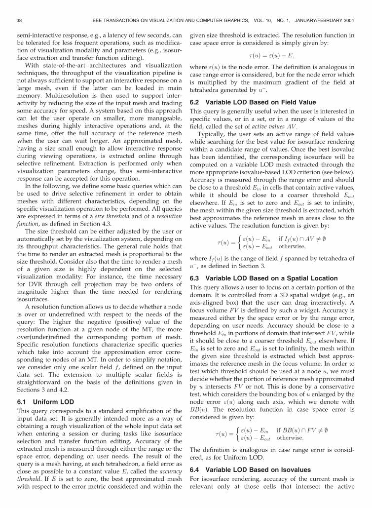
Fig. 1. Range error (a) and space error (b) in an approximated representation of a one-dimensional scalar data set. The original data set is drawn
with a thin line, the approximated data set with a bold line, and the error at some relevant points is represented by a dotted red line.

There is a differential relation between range error and
space error, which is given by the gradient of the field. In
our implementation, we decided to maintain only the space
error at each tetrahedron in the data structure encoding an
approximated data set and to estimate the corresponding
range error as
"F ð�0Þ ’ "Ið�0Þrð�0Þ;
where rð�0Þ is the magnitude of the largest gradient of a
component of F 0 on �0. Another possibility is maintaining
just the range error, but, in this case, the estimate of space
error would be divergent where the gradient is very low.
Since regions with low gradient are more common than
regions with very high gradient, we prefer the former
possibility.Giving an accurate measure of error in the output for
DVR techniques may be more complicated. In principle, an
approach similar to that used for defining the range error
can be used. By assuming an Euclidean distance in the
space RGB of colors, for a given field fj and a given transfer
function, the difference between the colors at each point P
of ��0 obtained through fj and f 0j, respectively, can be
computed. Such a difference is weighted with the alpha
value computed at fjðP Þ and the result is integrated over
��0 along the view direction. However, this definition of
error involves cumbersome computations that should be
performed at each change in view, with a computational
cost possibly higher than the straight DVR of the original
mesh. On the other hand, in our experiments, we found that
the visual differences in DVR images of approximated data
sets is closely related to range errors that occur in areas of
high opacity. Therefore, we have adopted a simpler
estimate of the transfer function error by just weighting the
range error with the alpha value. Given a tetrahedron �0, the
interval spanned by any component of F over ��0 is
contained in
IF ð�0Þ ¼ minf 0j2F 0
minP 02�0
f 0jðP 0Þ � "F ð�0Þ;max
f 0j2F 0maxP 02�0
f 0jðP 0Þ þ "F ð�0Þ" #
:
Interval IF ð�0Þ is easily obtained from the values of F 0 at the
vertices of �0. The maximum alpha value for a point inside
��0 is thus given by
�maxðF; �0Þ ¼ maxx2IF ð�0Þ
�ðxÞ;
where �ðÞ is the opacity component of the transfer function.
This value is easy to compute since �ðÞ is usually piecewise
linear. Then, we define the transfer function error as:
"DVRð�0Þ ¼ �maxð�0Þ"F ð�0Þ:
In Section 6, we will consider range error, space error,
and transfer function error to define multiresolution
visualization queries. Note that only the space error will
be maintained explicitly. Range error and transfer function
error are estimated, at each tetrahedron �0, on the basis of
space error, the geometry of �0, and the value of the field at
its vertices.
4 THE MULTIRESOLUTION MODEL
The multiresolution model at the heart of our approach is aspecific three-dimensional version of the general, dimen-sion-independent model introduced in [9], called the Multi-
Tessellation (MT). The algorithm for building such a modelis based on the mesh decimation method described in [3].The algorithm for selective refinement on the MT is similarto the one proposed in [8], improved with ideas from [11].
4.1 The Edge-Based Multi-Tessellation
Edge collapse [19] is a local update that acts on a tetrahedralmesh by contracting an edge e, with endpoints v0 and v00, toits midpoint v. The mesh around e is deformed by replacingvertices v0 and v00 with v and tetrahedra incident at both v0
and v00 collapse into triangles (see Fig. 2 from left to right).The reverse operation of an edge collapse, called a vertex
split, expands a vertex v into an edge e having its endpointsat v0 and v00. A vertex split partitions the tetrahedra incidentat v into two subsets, which are separated by a fan oftriangles incident at v. Tetrahedra of the two subsets aredeformed to become incident at v0 and v00, respectively.Triangles belonging to the fan become tetrahedra incident atboth v0 and v00 (see Fig. 2 from right to left).
Alternatively, an edge collapse can be seen as amodification that removes tetrahedra incident at v0 or v00
and replaces them with new tetrahedra incident at v. Avertex split can be seen as a modification that removestetrahedra incident at v and replaces them with newtetrahedra incident at v0 and v00.
A sequence of edge collapses transforms a referencemesh into a simplified mesh, while the correspondingsequence of vertex splits recovers the reference meshstarting at the simplified mesh. Fig. 3 shows a sequence ofvertex splits that progressively refine a triangle mesh (theexample is given in two dimensions, for the sake of clarity).
In the rest of the paper, we will use the followingnotation. A node u represents both an edge collapse u�
(coarsening update) and the corresponding vertex split uþ
(refinement update). The edge collapsed by applying u�
and the vertex split by applying uþ are denoted as eu and vu,respectively. Fig. 4a shows the nodes corresponding to thesequence of updates of Fig. 3.
CIGNONI ET AL.: SELECTIVE REFINEMENT QUERIES FOR VOLUME VISUALIZATION OF UNSTRUCTURED TETRAHEDRAL MESHES 33
Fig. 2. Modification of a tetrahedral mesh through an edge collapse anda vertex split (exploded view). On the left, tetrahedra that degenerateinto triangles after edge collapse are colored. On the right, tetrahedramarked with 0 and with 1 result from the deformation of tetrahedraincident at v0 and at v00.

An edge-based Multi-Tessellation is composed of a base
mesh at a coarse resolution plus a set of nodes defined asabove. A partial order among nodes is induced by thefollowing dependency relation: A node u depends on anothernode w if uþ removes some cell that has been introduced bywþ. This means that uþ cannot be applied unless wþ hasfirst been applied and, conversely, w� cannot be appliedunless u� has first been applied. Fig. 4b shows the partialorder encoded in the MT describing the sequence ofupdates depicted in Fig. 3.
We say that a subset S of nodes of an MT is consistent if,for every node u 2 S, all nodes w such that w precedes u inthe partial order are also in S. Nodes belonging to aconsistent subset S can be applied to the base mesh in anytotal order that extends the partial order, thus producing amesh �S .
The base mesh and the reference mesh are the coarsestand the most refined mesh that can be obtained from anMT, respectively. The reference mesh can be obtained fromthe base mesh by applying all vertex splits corresponding tonodes of the MT. Other meshes, at a virtually continuous setof levels of detail, can be extracted from an MT byperforming different consistent subsets of the updatescorresponding to its nodes. Consistency ensures that suchmeshes will not contain cracks or overlapping tetrahedra.
4.2 Construction of an Edge-Based MT
The construction of an edge-based MT is performed offlinethrough a variant of the simplification algorithm fortetrahedral meshes presented in [3]. The algorithm follows
a classical iterative approach: It starts with the reference
mesh and builds the MT by performing one edge collapse at
a time until a mesh of given size is obtained. An edge can be
collapsed only if the following conditions hold:
1. It does not introduce nonmanifold conditions;2. The total number of vertices adjacent to its two
endpoints is not larger than 32;3. Its two endpoints are not both local extrema (one
maximum and the other minimum) of any data fieldin the current mesh.
The algorithm collapses an edge to its middle point,
computing the value(s) of field(s) and the vertex normal(s)
at the new vertex by linear interpolation. In case one of the
endpoints of the edge is a local extreme value of some data
field in the current mesh, we assign that field value to the
new vertex instead. This fact, together with Condition 3
above guarantees that the range of the field in the influence
region of an edge collapse remains the same before and
after collapse, as required in Section 3. Condition 2 is
imposed essentially to guarantee a bound to the size of the
data structure that we use to encode collapses (see
Section 5.1). The experiments we have performed confirm
that this limit works well in practice.Each edge collapse generates a new node of the MT.
Dependencies on other MT nodes are detected and stored in
a data structure representing the partial order. The
simplified mesh obtained at the end of the simplification
process becomes the base mesh of the MT.
34 IEEE TRANSACTIONS ON VISUALIZATION AND COMPUTER GRAPHICS, VOL. 10, NO. 1, JANUARY/FEBRUARY 2004
Fig. 3. A sequence of vertex splits progressively refining a triangulation. The mesh portion affected by each update is shaded and the split vertex is
circled. The new edge introduced by a split is thickened.
Fig. 4. (a) The nodes corresponding to the example of Fig. 3. (b) The partial order among such updates, depicted as a DAG where each node
represents an update and each arc represents a dependency. Nodes are labeled with the indices of the corresponding split vertices.

Simplification is driven by a priority queue. A cost isassigned to each edge which is proportional to the increasein space error caused by its collapse. The edge of lowest costhas the highest priority. The priority queue is initializedwith all edges of the reference mesh which can be collapsedwithout violating mesh consistency and it is updated aftereach collapse by only updating those edges whose cost mayhave changed (i.e., only at edges in the proximity of thecollapsed edge).
The cost cðeuÞ of collapsing an edge is defined by themaximum of space errors evaluated at the tetrahedra �0
generated by the corresponding edge collapse. In order toget a correct estimation of the error, each vertex of theoriginal mesh that was eliminated because of a collapse isassigned to the tetrahedron containing it in the currentmesh (if a vertex lies outside the current mesh, then it isassigned to its closest tetrahedron in the mesh). The error ata tetrahedron �0 is computed by using the set of verticesassigned to �0 as a discrete approximation of ��0 . Theassignment of vertices to tetrahedra is updated locallyduring the simplification process. Once an edge eu iscollapsed and a corresponding node u is generated for theMT, we define and store the node error "ðuÞ ¼ cðeuÞ.
The construction algorithm assumes that the mesh has amanifold domain and makes sure that edge collapses do notintroduce nonmanifold features. The consistency of themultiresolution model guarantees that the same property ismaintained during selective refinement.
The current implementation of the MT constructionalgorithm works with just one field value per data set.However, the extension to deal with more field values isstraightforward.
Although the specific implementation presented in thispaper complies with the above description, we point outthat the mechanism for selective refinement and thevisualization system presented in the following sections iscompletely parametric with respect to the specific construc-tion technique and error metric adopted, as long as asequence of edge collapses is generated, which preservesthe manifold property of the mesh during simplification,and an error can be evaluated at each tetrahedron of anapproximated mesh.
4.3 An Incremental Algorithm for SelectiveRefinement
Selective refinement consists of extracting a tetrahedralmesh from an MT that fulfills some resolution requirementsand has a size smaller than or equal to a size threshold.
The selective refinement algorithm is based on anincremental approach, similar to the one proposed in [8],and improved with ideas from [11] (use of two priorityqueues). The algorithm starts with a consistent set S ofnodes of an MT and its associated mesh �S (called thecurrent set and the current mesh, respectively), which havebeen generated as the solution of a previous query. Atstartup, set S is empty and mesh �S is initialized to be thebase mesh. The algorithm modifies the current set (and thecurrent mesh, as a consequence) by iteratively adding anddeleting nodes to and from S. A node can be added to S, ordeleted from it, provided that the resulting set is stillconsistent (i.e., if and only if the corresponding update can
be made on �S). An update that can be performed withoutviolating consistency is called feasible. At each step, nodescorresponding to feasible edge collapses are considered fordeletion and nodes corresponding to feasible vertex splitsare considered for addition. Nodes to be inserted/deletedare selected on the basis of their priorities, which depend onresolution requirements.
Specific instances of resolution requirements, which areapplication dependent, will be defined in Section 6 forvarious queries related to volume visualization. In general,we assume that a resolution function �ðuÞ can be evaluatedat each node u of an MT, which defines the level ofresolution of node u, with respect to the desired require-ments. A value �ðuÞ > 0 means that the portion of meshcovered by u is underrefined (with respect to the currentrequirements) if vertex split uþ is not performed. A value�ðuÞ < 0 means that the portion of mesh covered by u isoverrefined (with respect to the current requirements) if edgecollapse u� is not performed. The larger the positive(negative) value of �ðuÞ, the more underrefined (over-refined) the portion of current mesh covered by u.
On this basis, a selective refinement on an MT produces amesh �S , associated with a consistent set S, such that: 1) Thesize of �S is � b, where b is the size threshold of the query;2) maxf�ðuÞ j u can be added to Sg is minimized;3) minf�ðuÞ j u can be deleted from Sg � 0. Requirement 1)can always be achieved, provided that threshold b is notsmaller than the size of the basemesh. Requirement 2)meansthat at least the most relevant vertex splits must be in S.Ideally, we would like to have no underrefined portions of amesh, but this can be achieved only if the size bound b is largeenough. Requirement 3) means that S must not contain anyoverrefinednode, i.e.,mesh�S mustbe the coarsestmesh thatcan be extracted based on requirements 1) and 2).
In order to perform priority-based insertions anddeletions, the selective refinement algorithm maintainstwo priority queues of nodes:
. A queue Qadd of candidate nodes to be added to set S(i.e., of candidate vertices to be split in �S). Qadd
contains the nodes u 62 S such that vertex vu belongsto �S , sorted by decreasing values of �ðuÞ.
. AqueueQdel of candidate nodes to be deleted from setS (i.e., of candidate edges to be collapsed in �S). Qdel
contains the nodes u 2 S such that edge eu is in�S andu� is feasible, sorted by increasing values of �ðuÞ.
Note that Qdel only contains feasible nodes, unlike Qadd.The algorithm consists of a loop in which the generic step
considers the values of � for the first nodes uadd in queueQadd and udel in queue Qdel and the size (#) of mesh �S . Therelevant cases and the actions taken by the algorithm ineach case are summarized below:
1. �ðudelÞ � 0, �ðuaddÞ, and #�S are any value: deleteudel from S and perform u�
del on �S .2. �ðudelÞ and �ðuaddÞ are any value, #�S > b: delete udel
from S and perform u�del on �S .3. �ðudelÞ > 0, �ðuaddÞ � 0, and #�S � b: exit and out-
put �S as the solution.4. �ðudelÞ > 0, �ðuaddÞ > 0, #�S � b: consider the set U
of all nodes u 62 S which are ancestors of uadd, and
CIGNONI ET AL.: SELECTIVE REFINEMENT QUERIES FOR VOLUME VISUALIZATION OF UNSTRUCTURED TETRAHEDRAL MESHES 35

test if the size of the mesh associated with S [ U [fuaddg is � b:
a. If true: add all nodes of U and node uadd to S; foreach node u added to S, perform uþ on �S .
b. If false and �ðudelÞ < �ðuaddÞ: delete udel from Sand perform u�
del on �S .c. If false and �ðuaddÞ � �ðudelÞ: exit and output �S
as the solution.
One or more applications of Case 4b will turn into a Case 4a
and, thus, will allow adding a node to S.After adding a node to S or deleting a node from it, the
two queues are updated by taking into account the new
situation in the neighborhood of the mesh portion that has
been modified.
5 A COMPACT DATA STRUCTURE FOR AN
EDGE-BASED MT
In order to encode an edge-based MT and to implement the
selective refinement algorithm described in Section 4, we
must maintain:
. A data structure for encoding the base mesh and thecurrent mesh, which supports edge collapses andvertex splits efficiently.
. Information about the partial order of the MTnodes, which allows testing whether an updateu� or uþ is feasible, and retrieving the directancestors of a node u.
. Information about updates u� and uþ correspondingto a node u of the MT, which allows applying suchupdates on the current mesh.
In order to manage large data sets, we have designed a
compact data structure which represents both the MT nodes
and the partial order in an implicit way. For encoding the
partial order, we elaborate on a result obtained by El-Sana
and Varshney [13] for the two-dimensional case. For
encoding nodes, we propose an original method based on
a bit vector.
5.1 Encoding the Base and the Current Meshes
Both the base mesh and the current mesh �S are encoded in
an adjacency-based data structure, implemented as an array
of vertices and an array of tetrahedra. For each vertex v, we
store:
v1. its three coordinates, the field value associatedwith v,and the normal (computed as explained in Section 3)at v;
v2. the index of one tetrahedron incident at v;v3. the index of the node corresponding to v in the MT
data structure.
For each tetrahedron t, we store:
t1. the indexes of the four vertices of t;t2. the indexes of the four tetrahedra adjacent to t along
a face;t3. the reverse indexes giving the position of t with
respect to each of its adjacent tetrahedra.
The dimension of the arrays used for the base mesh is
fixed. The dimension of arrays for the working structure
representing the current mesh is defined based on the given
size threshold b in such a way as to contain the largest
admissible mesh. Since the content of the structure is
dynamic, a simple mechanism of garbage collection (based
on reference counting) is used.We store four bytes per coordinate/value/index, four
bytes for the normal, and one byte for the reverse indexes. If�nn and �mm ( �mm � 6�nn) denote the number of vertices and
tetrahedra in a mesh, respectively, this data structure
requires 33 �mmþ 28 �nn ’ 226�nn bytes.The space required for the base mesh is, in general,
negligible because its size is typically about two orders of
magnitude smaller than the reference mesh. The space
required by the current mesh depends on the size threshold.Note that this data structure, except for field v3 (4 bytes),
is the same as a standard adjacency-based data structure
that is necessary to support DVR through cell projection,
which would therefore cost 222�nn bytes. For visualization
through isosurfaces or cross sections, a data structure
storing just fields v1 and t1 is sufficient. This structure,
which is usually called an indexed data structure, would
require 16 �mmþ 20 �nn ’ 116 �nn bytes.
5.2 Encoding the Partial Order
Since an explicit encoding of the DAG describing the partial
order could be too expensive, we encode it implicitly
through a mechanism proposed by El-Sana and Varshney
[13] for triangle meshes. This mechanism is based on a
binary forest of vertices and on a vertex enumeration
scheme.The forest contains one node for each vertex of the MT
and one node for each vertex of the reference mesh. The
leaves of the forest correspond to the vertices of the
reference mesh, while the other nodes are in a one-to-one
correspondence with the MT nodes. In particular, the roots
correspond to vertices of the base mesh. The two children of
each internal node vu correspond to the endpoints v0u and v00uof the edge eu created when splitting vu. Fig. 5 shows the
forest for the MT of Fig. 4.The n vertices of the reference mesh are labeled
arbitrarily with numbers from 1 to n. The remaining
vertices are assigned consecutive numbers in a total order
that extends the partial order of the MT. An example of
enumeration can be seen in Fig. 3 by reading the figure from
right to left as a sequence of edge collapses. In this way, if a
node u depends on node w in the MT, then the label of
vertex vu must be lower than that of vw.
36 IEEE TRANSACTIONS ON VISUALIZATION AND COMPUTER GRAPHICS, VOL. 10, NO. 1, JANUARY/FEBRUARY 2004
Fig. 5. The forest of binary trees encoding the MT of Fig. 4. Circles
represent vertices corresponding to MT nodes, squares represent
vertices of the original mesh.

The forest can be implemented as an array in whichevery node u is stored at the position corresponding to itslabel. The entry for u stores:
. an index u:WIDE which points either to the parentup of u, if u is the second child of up (by convention,the child having the smallest label), or to the siblingof u, if u is the first child of up,
. an index u:DEEP pointing to the first child of u (byconvention, the child having the largest label).
The parent of a node u is determined as u:WIDE, ifu:WIDE > u, or as u:WIDE:WIDE otherwise. The childrenof u are found as u:DEEP and u:DEEP:WIDE.
Note that a leaf u of the forest requires just indexu:WIDE. Therefore, our implementation consists of twoseparate arrays, one for the leaves and one for the internalnodes. The storage cost of maintaining the forest is equal to4 nþ 8 nin ’ 12n bytes, where n is the number of vertices ofthe reference mesh (i.e., of leaves in the forest) and nin is thenumber of internal nodes (nin ’ n).
Given a mesh �S corresponding to a consistent set S, thefollowing properties hold [13]:
1. A vertex split uþ is feasible on �S if and only ifvertex vu belongs to �S and all the labels of verticesadjacent to vu are lower than that of vu. If u
þ is notfeasible, then it can be made feasible by first splittingall the adjacent vertices of vu which have a labelgreater than vu. If any of such adjacent splits is notfeasible, the rule is recursively applied.
2. An edge collapse u� is feasible on �S if and only ifedge eu belongs to �S and, for each vertex w adjacentto the endpoints of eu in �S , either w is one of theroots in the forest or the label of the parent of w isgreater than that of vu.
5.3 Encoding MT Nodes
Information stored for a node u of the MT must be sufficientto perform both operations u� (edge collapse) and uþ
(vertex split) on the current mesh �S . All geometric andattribute information about each vertex of the current meshare maintained in the working data structure for �S , whichis dynamically linked to the corresponding node of theforest. In particular, each entry corresponding to a vertex ofthe current mesh has a pointer to the node in the forestcorresponding to the same vertex (see Section 5.1).
Let u� be a feasible edge collapse for �S , which shouldcontract an edge eu, having as endpoints a pair of vertices v0uand v00u, to a vertex vu. Since we have built the MT bycollapsing edges to their midpoints, the position, field, andvertex normals of vertex vu are obtained by linearinterpolation. We modify �S by replacing v0u or v00u with vuin all tetrahedra containing either of such two vertices anddeleting those tetrahedra which become degenerate. Thecurrent mesh, together with the forest, provides sufficientinformation to support edge collapse.
Conversely, let uþ be a feasible vertex split for �S , whichshould expand vertex vu into edge eu with endpoints v0u andv00u. In order to perform uþ, we also need to know thepositions, field values, and normals of v0u and v00u, and apartition of the tetrahedra incident into vu into tetrahedra
that must replace vu with v0u and tetrahedra that mustreplace v00u. For this purpose, we store the followingadditional information at a node u:
. an offset vector, which is used to find the positionsof vertices v0u and v00u from that of vu,
. an offset value, which is used to obtain the fieldvalues at v0u and v00u from that of vu,
. the normal nv0u of v0. The other normal nv00u of v00 canbe found as 2 � nvu � nv0u , where nvu is the normal atvu.
. a bit mask which is used to partition the star of vu,i.e., the set of tetrahedra incident at vu.
The bit mask contains one bit for each tetrahedron incident atvu. Incident tetrahedra are sorted lexicographically accordingto the triplets formed by their vertices different from vu,where the vertices are sorted according to their index. Then,the following rule is applied: Tetrahedramarkedwith 0mustreplace vu with v0u; tetrahedra marked with 1 must replace vuwith v00u; each triangular face shared by two differentlymarked tetrahedra must be expanded into a tetrahedronincident at both v0u and v00u (see Fig. 2, right side).
In order to resolve ambiguities in boundary configura-tions, we assume the existence of dummy tetrahedraattached to the faces lying on the mesh boundary andincident to a dummy vertex. In the case of a boundaryupdate u, the bit vector includes one bit for each dummytetrahedron.
In selective refinement, the evaluation of the priorityfunction �ðuÞ for an update u may depend on the nodeerror, as described in Section 4.2. Therefore, we also storesuch a value at each node u.
Since we collapse only edges so that the total number ofadjacent vertices to their two endpoints is not larger than 32(see Section 4.2), the number of tetrahedra incident in avertex is bounded by 64 and, thus, the bit mask can bestored in 8 bytes. Moreover, we compress the normal andthe error to 4 bytes: We pack the normal in the first 18 bitsby using the compression scheme described in [10] and wequantize the node error on the remaining 14 bits, using alogarithmic scale to have a finer grained quantization atsmall errors.
The storage cost for the information associated with asingle node contributes for a cost of 28 bytes. Since this cost isadded to all nin ’ n entries of the array of internal nodes, thetotal cost of the MT data structure is 12nþ 28n ¼ 40n bytes,plus the cost of the base mesh, which is negligible. Thus, ourdata structure for the MT achieves a compression factor ofabout 5.5 or 3, compared with the mesh at full resolutionencoded into an adjacency-based data structure or into anindexed one, respectively, as reported in Section 5.1.
6 SELECTIVE REFINEMENT QUERIES
An interactive response is crucial for the effective use of avisualization system. In a context where volume data areanalyzed and rendered through different techniques, suchas isosurfaces, planar cross sections, and DVR, thefollowing requirements should be fulfilled: Standardviewing operations, such as data rotation, panning, andzooming must be performed at a rate of at least 10 fps; a
CIGNONI ET AL.: SELECTIVE REFINEMENT QUERIES FOR VOLUME VISUALIZATION OF UNSTRUCTURED TETRAHEDRAL MESHES 37
semi-interactive response, e.g., a latency of few seconds, canbe tolerated for less frequent operations, such as modifica-tion of visualization modality and parameters (e.g., isosur-face extraction and transfer function editing).
With state-of-the-art architectures and visualizationtechniques, the throughput of the visualization pipeline isnot always sufficient to support an interactive response on alarge mesh, even if the latter can be loaded in mainmemory. Multiresolution is then used to support inter-activity by reducing the size of the input mesh and tradingsome accuracy for speed. A system based on this approachcan let the user operate on smaller, more manageable,meshes during highly interactive operations and, at thesame time, offer the full accuracy of the reference meshwhen the user can wait longer. An approximated mesh,having a size small enough to allow interactive responseduring viewing operations, is extracted online throughselective refinement. Extraction is performed only whenvisualization parameters change, thus semi-interactiveresponse can be accepted for this operation.
In the following, we define some basic queries which canbe used to drive selective refinement in order to obtainmeshes with different characteristics, depending on thespecific visualization operation to be performed. All queriesare expressed in terms of a size threshold and of a resolutionfunction, as defined in Section 4.3.
The size threshold can be either adjusted by the user orautomatically set by the visualization system, depending onits throughput characteristics. The general rule holds thatthe time to render an extracted mesh is proportional to thesize threshold. Consider also that the time to render a meshof a given size is highly dependent on the selectedvisualization modality: For instance, the time necessaryfor DVR through cell projection may be two orders ofmagnitude higher than the time needed for renderingisosurfaces.
A resolution function allows us to decide whether a nodeis over or underrefined with respect to the needs of thequery: The higher the negative (positive) value of theresolution function at a given node of the MT, the moreover(under)refined the corresponding portion of mesh.Specific resolution functions characterize specific querieswhich take into account the approximation error corre-sponding to nodes of an MT. In order to simplify notation,we consider only one scalar field f , defined on the inputdata set. The extension to multiple scalar fields isstraightforward on the basis of the definitions given inSections 3 and 4.2.
6.1 Uniform LOD
This query corresponds to a standard simplification of theinput data set. It is generally intended more as a way ofobtaining a rough visualization of the whole input data setwhen entering a session or during tasks like isosurfaceselection and transfer function editing. Accuracy of theextracted mesh is measured through either the range or thespace error, depending on user needs. The result of thequery is a mesh having, at each tetrahedron, a field error asclose as possible to a constant value E, called the accuracythreshold. If E is set to zero, the best approximated meshwith respect to the error metric considered and within the
given size threshold is extracted. The resolution function incase space error is considered is simply given by:
�ðuÞ ¼ "ðuÞ �E;
where "ðuÞ is the node error. The definition is analogous incase range error is considered, but for the node error whichis multiplied by the maximum gradient of the field attetrahedra generated by u�.
6.2 Variable LOD Based on Field Value
This query is generally useful when the user is interested inspecific values, or in a set, or in a range of values of thefield, called the set of active values AV .
Typically, the user sets an active range of field valueswhile searching for the best value for isosurface renderingwithin a candidate range of values. Once the best isovaluehas been identified, the corresponding isosurface will becomputed on a variable LOD mesh extracted through themore appropriate isovalue-based LOD criterion (see below).Accuracy is measured through the range error and shouldbe close to a threshold Ein in cells that contain active values,while it should be close to a coarser threshold Eout
elsewhere. If Ein is set to zero and Eout is set to infinity,the mesh within the given size threshold is extracted, whichbest approximates the reference mesh in areas close to theactive values. The resolution function is given by:
�ðuÞ ¼ "ðuÞ �Ein if IfðuÞ \AV 6¼ ;"ðuÞ �Eout otherwise;
�
where IfðuÞ is the range of field f spanned by tetrahedra ofu�, as defined in Section 3.
6.3 Variable LOD Based on a Spatial Location
This query allows a user to focus on a certain portion of thedomain. It is controlled from a 3D spatial widget (e.g., anaxis-aligned box) that the user can drag interactively. Afocus volume FV is defined by such a widget. Accuracy ismeasured either by the space error or by the range error,depending on user needs. Accuracy should be close to athreshold Ein in portions of domain that intersect FV , whileit should be close to a coarser threshold Eout elsewhere. IfEin is set to zero and Eout is set to infinity, the mesh withinthe given size threshold is extracted which best approx-imates the reference mesh in the focus volume. In order totest which threshold should be used at a node u, we mustdecide whether the portion of reference mesh approximatedby u intersects FV or not. This is done by a conservativetest, which considers the bounding box of u enlarged by thenode error "ðuÞ along each axis, which we denote withBBðuÞ. The resolution function in case space error isconsidered is given by:
�ðuÞ ¼ "ðuÞ � Ein if BBðuÞ \ FV 6¼ ;"ðuÞ � Eout otherwise:
�
The definition is analogous in case range error is consid-ered, as for Uniform LOD.
6.4 Variable LOD Based on Isovalues
For isosurface rendering, accuracy of the current mesh isrelevant only at those cells that intersect the active
38 IEEE TRANSACTIONS ON VISUALIZATION AND COMPUTER GRAPHICS, VOL. 10, NO. 1, JANUARY/FEBRUARY 2004

isovalues. This query is intended as a mean to display anaccurate isosurface once an interesting isovalue has beenidentified. Given a collection of isovalues IV , accuracy,measured by the space error, should be close to a thresholdEin in portions of domain that intersect IV , while it can bearbitrarily large elsewhere. In case Ein is set to zero, theextracted isosurfaces coincide with those obtained from thereference mesh. The resolution function is given by:
�ðuÞ ¼ "ðuÞ � Ein if IfðuÞ \ IV 6¼ ;�1 otherwise;
�
where IfðuÞ is the range of field f spanned by tetrahedra ofu�, as defined in Section 3.
6.5 Variable LOD Based on the Transfer Function
This query is reserved for the DVR modality. It permits usto have an accuracy proportional to the opacity of the fieldwith respect to the current transfer function. In this case, theextracted mesh is the mesh within the given size thresholdhaving the best accuracy, which is measured by the transferfunction error. The resolution function is simply given by
�ðuÞ ¼ "DVRfðuÞ;
where "DVRfis the transfer function error at a node u, as
defined as in Section 3.Besides reducing the size of the current mesh, this
approach may produce visual results that are even betterthan those obtained by using the reference mesh. In fact, theuse of high resolution everywhere may introduce consider-able quantization error in regions with low opacity becausemost current graphics subsystems support only one byteper RGBA channel. Thus, small size cells with a very lowopacity would be rendered as completely transparent. Onthe contrary, the contribution of low opacity regions is notlost if larger cells are used over them.
Our approach could support other LOD criteria as well.In particular, view-dependent criteria could be definedsimply by using the projected value of space error on thescreen, rather than space error itself, in defining the variousresolution functions. However, in our opinion, view-dependent LOD is of marginal importance in volumevisualization since we typically deal with a single volumedata set that has small extension in space compared to thedistance from the viewer. Moreover, view-dependent LODwould force us to make a new selective refinement eachtime a view operation is performed, i.e., during interactiveviewing, which is not supported in the current implementa-tion. For these reasons, we did not implement view-dependent criteria in our prototype system.
7 THE TAN2 SYSTEM
TAn2 is an interactive visualization system that uses anedge-based MT to efficiently generate isosurfaces, planarcross sections, and direct volume rendering.
The architecture ofTAn2 consists of sixmodules, as shownin Fig. 6. It is mainly based on aMultiresolution Enginewhich,according to the user’s needs, performs selective refinementoperations on the MT data structure and extracts tetrahedralmeshes. The most recently generated tetrahedral model is
maintained in Current Model Manager and is subsequently
used by all the other rendering and interaction modules.
The algorithms used for isosurface extraction and DVR are
standard algorithms, which require short setup times. In
this prototype system, we have favored the simplicity of
such algorithms. On the other hand, given the modular
structure of the system, they can be easily replaced with
more advanced and efficient ones. The six modules and
their interactions are described below:
1. The GUI Manager, which manages the user interface(except for rendering) and controls user interaction.It provides GUI devices for three main classes ofoperations: viewing operations (rotation, zooming,and panning of the visualized object), visualizationoperations (editing of the transfer function, selectionof isovalues, and cross planes), and multiresolutionoperations (selection of a LOD query, selection ofsize and accuracy thresholds, and manual request toperform a mesh extraction).
2. The Transfer Function Manager, which stores allresolution and visualization parameters receivedfrom the user through the GUI manager. Suchparameters are the field-to-color mapping (definedby piecewise-linear functions on the RGBA compo-nents), used to assign colors to the vertices of thecurrent mesh to be rendered; the active isovalues,used to generate the isosurfaces; the active cross planeparameters, used to generate cross sections; thecurrent size threshold; and the accuracy thresholds.
3. The Multiresolution Engine, which performs selectiverefinement on the MT data structure each time itreceives new user-defined thresholds from theTransfer Function Manager.
4. The Current Model Manager, which stores the currentmesh enriched with additional information requiredfor rendering, including colors (received from theTransfer Function Manager), isosurfaces, and crosssections (computed by the Isosurface Engine, seebelow).
CIGNONI ET AL.: SELECTIVE REFINEMENT QUERIES FOR VOLUME VISUALIZATION OF UNSTRUCTURED TETRAHEDRAL MESHES 39
Fig. 6. The architecture of the TAn2 system.

5. The Isosurface Engine, which extracts isosurfaces andcross planes from the current mesh, based onparameters received from the Transfer FunctionManager. Both isosurfaces and cross planes arecomputed through a standard Marching Tetrahedraalgorithm. The normals of the isosurface at itsvertices are computed according to the vertexnormal stored into the tetrahedral model, as definedin Section 3.
6. The Rendering Engine, which performs renderingthrough isosurfaces, cross sections, and DVR. It canrender a data set by drawing its points, the edges ofthe tetrahedral mesh, or the triangle mesh formingits boundary. The DVR approach adopted is basedon depth-sorting and composition of the contribu-tion of the tetrahedral cells [33], [38]. The depthsorting of the tetrahedral mesh is based on anapproximate centroid sorting of boundary cellsfollowed by a topological sort of internal cells. Wehave included in the system a more sophisticatedrendering mode that allows rendering the isosur-faces together with the DVR cell contributionaccording to the current TF (see Fig. 11). A morecorrect depth sorting algorithm, like the one of [7],could be also added.
8 RESULTS
In this section, we show images and performance statisticsobtained from TAn2 on four sample data sets:
. Fighter (13,832 vertices, 70,125 tetrahedra): Anirregular tetrahedral mesh which is the result of anair flow simulation over a jet fighter from a windtunnel model developed at NASA Langley ResearchCenter (courtesy of R.W. Neely and J.T. Batina,NASA, 1992);
. BluntFin (40,960 vertices, 222,528 tetrahedra): Air-flow over a flat plate with a blunt fin rising from the
plate (courtesy of C.M. Hung and P.G. Buning,NASA, 1990);
. Turbine Blade (106,795 vertices, 576,576 tetrahedra):A curvilinear mesh (courtesy of AVS Inc., tetrahe-dralized by O.G. Staadt);
. Plasma64 (262,144 vertices, 1,500,282 tetrahedra): Alarge regular synthetic data set of three-dimensionalPerlin noise [30].
The first two data sets have multiple fields: We have usedjust one of them, namely, the density field, for our experi-ments. The initial tetrahedral mesh of Plasma64 has beenobtained from the regular grid by decomposing each cubiccell into six tetrahedra. Curvilinear grids (BluntFin andTurbine Blade) are cubic grids to which deformations havebeen applied and have been tetrahedralized in a similar way.We needed to start from regular data sets because fewirregular data sets are available in the public domain due tothe security policies of research agencies and industries.
The above data sets have been chosen to present a set ofdifferent characteristics. Fighter has a very complex bound-ary with small scale features (such as thin wings). BluntFinhas an extremely uneven cell distribution. Turbine Blade is arather large data set, with many degenerate cells (i.e., cellswith zero volume). Plasma64 is the largest one and its fielddistribution contains strong variations of gradient; there-fore, it cannot be approximated well with linear patches,i.e., concise representations are hard to obtain for it. Thisfeature of the Plasma64 data set is exemplified by the fourisosurfaces depicted in Fig. 7a. All experiments have beenperformed on a Pentium III at 800 MHz.
Table 1 shows the statistical parameters characterizingthe four meshes. The average size of an isosurface on thesedata sets has been computed by considering nine fieldvalues equally distributed in the data set field range. Notethat if we use standard rendering techniques and low costPC hardware, then isosurface visualization of the twolargest data sets often runs at noninteractive frame rates(especially if displaying several isosurfaces at a time).
40 IEEE TRANSACTIONS ON VISUALIZATION AND COMPUTER GRAPHICS, VOL. 10, NO. 1, JANUARY/FEBRUARY 2004
Fig. 7. Two images for the Plasma64 data set: (a) Four isosurfaces extracted from the mesh at full resolution to show the complexity of the field.
(b) Two isosurfaces from a mesh at variable LOD based on isovalue with threshold Ein ¼ 0:0%. The size of the selectively refined mesh is only about
7 percent of the size of the reference mesh.

Moreover, interactive DVR rendering usually runs atnoninteractive frame rates on all the data sets consideredin the experiments.
The simplification process used to build the MTs (asdescribed in Section 4.2) is accurate but far from beinginteractive. For instance, simplifying the Plasma64 and theTurbine data sets required about 35 minutes and 13 minutes,respectively.
Table 2 reports results about the extraction of meshes at auniform LOD based on the field error from the MTs ofPlasma64 and Turbine data sets. Meshes are extracted withthe selective refinement algorithm, starting at the base meshof the MT, thus in the worst possible situation. Indeed, thenumber of updates (vertex splits) necessary in this case toextract a mesh is roughly equal to the number of its vertices.Better performances are obtained in a more dynamiccontext, where a mesh is extracted starting from anothermesh, larger than the base mesh, thus requiring a smallernumber of updates. On average, we have found that theselective refinement algorithm can process about 60Kupdates per second. This is sufficient to guarantee extrac-tion in semi-interactive time for even the largest mesh wehave considered.
Table 3 reports results of isosurface generation onmeshes extracted with variable LOD based on isovalue from
the Plasma64 data set. Note that, with an accuracy thresholdEin ¼ 0:0, we obtain fully accurate isosurfaces, while thesize of meshes from which they are extracted spans between3 percent (best case) and 58 percent (worst case) of the sizeof the reference mesh. Thus, when the change in isosurfaceis small, computing isosurfaces with Ein ¼ 0:0 can be fasterthan computing them on the reference mesh. Fig. 7b showstwo isosurfaces, together with wire frame of the boundaryof the selectively refined tetrahedral mesh. Note how onlythe portion of mesh close to isosurfaces contains cells athigh resolution.
Also, in this case, times for selective refinement are takenin the worst case, i.e., each refinement is performed startingat the base mesh. In practical applications, the userselectively refines a mesh by focusing on a range ofinteresting values, then she/he repeatedly extracts andvisualizes isosurfaces from that mesh. Moreover, if the userdecides next to focus on a different, but close, range ofvalues, then the time necessary for selective refinement willbe much shorter.
If an isosurface intersects a large fraction of tetrahedra,even a mesh extracted at a variable LOD cannot be veryconcise. In this case, variable LOD based on spatial location canbe combined with variable LOD based on isovalue in order toincrease data reduction further, by focusing on a subvolume
CIGNONI ET AL.: SELECTIVE REFINEMENT QUERIES FOR VOLUME VISUALIZATION OF UNSTRUCTURED TETRAHEDRAL MESHES 41
TABLE 1Parameters Characterizing the Meshes Used in the Experiments
Number of vertices and of tetrahedra in the mesh, size (number of triangles) of the triangulated surface bounding the mesh, field range, average size(number of triangles) of an isosurface.
TABLE 2Meshes Extracted at a Uniform LOD from an MT for Plasma64 and Turbine
Number of vertices and tetrahedra of meshes are shown, together with time to extract them starting at the base mesh.
TABLE 3Results of Isosurface Generation from Meshes at a Variable LOD Based on Isovalue from the Plasma64 Data Set
Times are in milliseconds.

of interest. A focus box, such as those depicted in Fig. 8 and
Fig. 9, can be dragged interactively since only a few
thousand updates are necessary to selectively refine a mesh
after moving the box.The comparison of results presented in Tables 2 and 3
confirms that the availability of tools for refining the mesh
representation only in selected regions, according to criteria
based on field and space, permits us to generate concise
meshes that also give an accurate representation of the data
set. The multiresolution approach shows its benefit espe-
cially on large data sets, such as Plasma64 and Turbine, and
at high resolutions.Fig. 8 shows two isosurfaces extracted from BluntFin by
using variable LOD based on spatial location. The size of the
tetrahedral mesh is about 1/3 of the size of the reference
mesh (64K cells instead of 222K cells) and the error bound
inside the box is 0.01 percent of the field range. Images in
Fig. 9 also refer to variable LOD based on spatial location, but
they just show the boundary mesh of Fighter, with zero
error inside the box. The two meshes are of approximately
the same size, which is about 1/4 of the size of the reference
mesh (16K cells instead of 70K cells) and correspond to
different positions of the focus volume.In Figs. 10 and 11, more complex examples of rendering
from variable LOD meshes are shown. Fig. 10 shows an
image of the Turbine data set obtained by extracting a mesh
at variable LOD based on spatial location by focusing on a cross
plane. The size threshold is 40K tetrahedra, and the error
threshold is 2.0 percent of field range. The cross plane is
visualized together with one isosurface and the wire frame
of the mesh boundary. In Fig. 11, the same mesh is rendered
with DVR and hybrid DVR and isosurface rendering.
42 IEEE TRANSACTIONS ON VISUALIZATION AND COMPUTER GRAPHICS, VOL. 10, NO. 1, JANUARY/FEBRUARY 2004
Fig. 8. BluntFin data set. Two isosurfaces from a mesh at variable LOD based on spatial location, obtained by using a box as a focus volume (full and
zoomed view).
Fig. 9. The two images show how well the multiresolution model preserves the fine-grain detail on the mesh boundary: No self-intersection or strong
variation from the original surface are introduced on the mesh boundary.

9 CONCLUDING REMARKS
In this paper, we have addressed the problem of efficiently
visualizing large irregular volume data sets by using a
multiresolution model. The model is a specialization of the
Multi-Tessellation (MT) [9] for tetrahedral meshes simpli-
fied through edge-collapse operations. We have defined
LOD queries on an MT suitable to support volumevisualization operations. A new compact data structurehas been provided for a three-dimensional MT built basedon a sequence of general edge collapses, which is about 3 to5.5 times smaller than a standard data structure encodingjust the reference mesh. We have briefly described TAn2(Tetrahedra Analyzer 2), an interactive system for visualiza-tion of three-dimensional scalar fields that we haveimplemented based on the concepts and methods presentedin this paper. The system supports common renderingtechniques for 3D data (isosurface fitting, cross planes andDVR) and can deal with large irregular data sets thanks tothe multiresolution approach. To our knowledge, TAn2 isthe only volume visualization system supporting onlineselective refinement on unstructured meshes and able todeal with irregular and nonconvex data sets efficiently.
Further possible extensions of the work presented hereare concerned with the support of more sophisticatedrendering features, including the use of more effectivevisualization-oriented error metrics, and with the out-of-core management of the multiresolution model.
In particular, out-of-core techniques would allow us todeal with data sets that are not just too large to be rendered,but even too large to be stored in main memory. Our futureresearch work will be devoted to the design and develop-ment of data structures for encoding an edge-based MT onsecondary storage and of out-of-core algorithms [6] for itsconstruction and selective refinement. If such techniqueswere available, it would be easy to integrate them in TAn2,due to the modular architecture of the system, by simplyreplacing its Multiresolution Engine.
ACKNOWLEDGMENTS
The authors wish to thank Raffaele Dell’Aversana andDavide Sobrero for implementing parts of the TAn2 system.
CIGNONI ET AL.: SELECTIVE REFINEMENT QUERIES FOR VOLUME VISUALIZATION OF UNSTRUCTURED TETRAHEDRAL MESHES 43
Fig. 10. An image of the Turbine data set produced from a mesh at a
variable LOD based on spatial location focusing on a cross plane.
Fig. 11. A DVR image (a) and a hybrid image, which integrates isosurfaces plus DVR (b) from the same mesh used in Fig. 10.

This work has been partially supported by the Research
Training Network EC Project on Multiresolution in Geometric
Modeling (MINGLE), under contract HPRN-CT-1999-00117,
by the EC Project Virtual Planet within the Fifth Framework
Program for Information Society Technologies, under
contract IST-2000-28095, and by the National Project funded
by the Italian Ministry of Education, University and
Research (MIUR) on Representation and Processing of Spatial
Data in Geographic Information Systems.
REFERENCES
[1] Y. Chiang and C.T. Silva, “I/O Optimal Isosurface Extraction,”Proc. IEEE Visualization ’97, R. Yagel and H. Hagen, eds., 1997.
[2] Y. Chiang and C.T. Silva, “Interactive Out-of-Core IsosurfaceExtraction,” Proc. IEEE Visualization ’98, pp. 167-174, 1998.
[3] P. Cignoni, D. Costanza, C. Montani, C. Rocchini, and R.Scopigno, “Simplification of Tetrahedral Volume with AccurateError Evaluation,” Proc. IEEE Visualization 2000, pp. 85-92, 2000.
[4] P. Cignoni, L. De Floriani, C. Montani, E. Puppo, and R. Scopigno,“Multiresolution Modeling and Rendering of Volume Data Basedon Simplicial Complexes,” Proc. 1994 Symp. Volume Visualization,pp. 19-26, 1994.
[5] P. Cignoni, C. Montani, E. Puppo, and R. Scopigno, “Multi-resolution Modeling and Visualization of Volume Data,” IEEETrans. Visualization and Computer Graphics, vol. 3, no. 4, pp. 352-369, Oct.-Dec. 1997.
[6] P. Cignoni, C. Montani, C. Rocchini, and R. Scopigno, “ExternalMemory Management and Simplification of Huge Meshes,” IEEETrans. Visualization and Computer Graphics, to appear.
[7] J. Comba, J.T. Klosowski, N. Max, J.S.B. Mitchell, C.T. Silva, andP.L. Williams, “Fast Polyhedral Cell Sorting for InteractiveRendering of Unstructured Grids,” Computer Graphics Forum(Eurographics ’99 Conf. Issue), vol. 18, no. 3, pp. C369-C376, 1999.
[8] L. De Floriani, P. Magillo, F. Morando, and E. Puppo, “DynamicView-Dependent Multiresolution on a Client-Server Architec-ture,” CAD J., vol. 32, no. 13, pp. 805-823, 2000.
[9] L. De Floriani, E. Puppo, and P. Magillo, “A Formal Approach toMultiresolution Modeling,” Geometric Modeling: Theory and Prac-tice, R. Klein, W. Straßer, and R. Rau, eds., Springer-Verlag, 1997.
[10] M. Deering, “Geometry Compression,” Computer Graphics Proc.,Ann. Conf. Series (SIGGRAPH ’95), pp. 13-20, 1995.
[11] M. Duchaineau, M. Wolinsky, D.E. Sigeti, M.C. Miller, C. Aldrich,M.B. Mineed-Weinstein, “ROAMing Terrain: Real-Time Opti-mally Adapting Meshes,” Proc. IEEE Visualization ’97, pp. 81-88,1997.
[12] B. Hamann, E. LaMar, and K.I. Joy, “High-Quality Rendering ofSmooth Isosurfaces,” J. Visualization and Computer Animation,vol. 10, pp. 79-90, 1999.
[13] J. El-Sana and A. Varshney, “Generalized View-DependentSimplification,” Computer Graphics Forum, vol. 18, no. 3, pp. C83-C94, 1999.
[14] R. Farias, J.S. Mitchell, C.T. Silva, and B. Wylie, “Time-CriticalRendering of Irregular Grids,” Proc. Sibgrapi 2000 (XIII BrazilianSymp. Computer Graphics and Image Processing), pp. 243-250, 2000.
[15] R. Farias and C.T. Silva, “Out-of-Core Rendering of Large,Unstructured Grids,” IEEE Computer Graphics and Applications,vol. 21, no. 4, pp. 42-50, July/Aug. 2001.
[16] L. De Floriani and P. Magillo, “Multiresolution Meshes,” Principlesof Multiresolution in Geometric Modeling—PRIMUS Summer School,Munich, Aug. 2001.
[17] M. Garland, “Multiresolution Modeling: Survey & Future Oppor-tunities,” Eurographics ’99—State of the Art Reports, pp. 111-131,1999.
[18] T. Gerstner and R. Pajarola, “Topology Preserving and ControlledTopology Simplifying Multiresolution Isosurface Extraction,”Proc. IEEE Visualization 2000, pp. 259-266, 2000.
[19] M.H. Gross and O.G. Staadt, “Progressive Tetrahedralizations,”Proc. IEEE Visualization ’98, pp. 397-402, 1998.
[20] R. Grosso, C. Luerig, and T. Ertl, “The Multilevel Finite ElementMethod for Adaptive Mesh Optimization and Visualization ofVolume Data,” Proc. IEEE Visualization ’97, R. Yagel and H. Hagen,eds., pp. 387-394, 1997.
[21] A. Gueziec, G. Taubin, F. Lazarus, and W. Horn, “Simplicial Mapsfor Progressive Transmission of Polygonal Surfaces,” Proc. ACMInt’l Conf. Virtual Reality and Modeling Language (VRML ’98), pp.25-31, 1998.
[22] I. Ihm and S. Park, “Wavelet-Based 3D Compression Scheme forVery Large Volume Data,” Proc. Graphics Interface, pp. 107-116,1998.
[23] T. Kim and Y. Shin, “An Efficient Wavelet-Based CompressionMethod for Volume Rendering,” Proc. Pacific Graphics 1999,pp.147-157, 1999.
[24] M. Lee, L. De Floriani, and H. Samet, “Constant-Time NeighborFinding in Hierarchical Meshes,” Proc. Int’l Conf. Shape Modeling,2001.
[25] P. Lindstrom, “Out-of-Core Simplification of Large PolygonalModels,” Computer Graphics Proc., Ann. Conf. Series (SIGGRAPH2000), pp. 259-262, 2000.
[26] D. Luebke and C. Erikson, “View-Dependent Simplification ofArbitrary Polygonal Environments,” ACM Computer GraphicsProc., Ann. Conf. Series (SIGGRAPH ’97), pp. 199-207, 1997.
[27] S. Muraki, “Volume Data and Wavelet Transforms,” IEEEComputer Graphics and Applications, vol. 13, no. 4, pp. 50-56, July1993.
[28] M. Ohlberger and M. Rumpf, “Adaptive Projection Operators inMultiresolution Scientific Visualization,” IEEE Trans. Visualizationand Computer Graphics, vol. 5, no. 1, pp. 74-93, Jan.-Mar. 1999.
[29] V. Pascucci and C.L. Bajaj, “Time Critical Isosurface Refinementand Smoothing,” Proc. 2000 IEEE Symp. Volume Visualization,pp. 33-42, 2000.
[30] K. Perlin and E.M. Hoffert, “Hypertexture,” Computer Graphics(SIGGRAPH ’89 Proc.), vol. 23, no. 3, pp. 253-262, 1989.
[31] J. Popovic and H. Hoppe, “Progressive Simplicial Complexes,”ACM Computer Graphics Proc., Ann. Conf. Series (SIGGRAPH ’97),pp. 217-224, 1997.
[32] R. Shekhar, E. Fayyad, R. Yagel, and J. Cornhill, “Octree-BasedDecimation of Marching Cubes Surfaces,” Proc. IEEE Visualization’96, R. Yagel and G. Nielson, eds., pp. 335-344, 1996.
[33] P. Shirley and A. Tuchman, “A Polygonal Approximation toDirect Scalar Volume Rendering,” Computer Graphics (San DiegoWorkshop Volume Visualization), vol. 24, no. 5, pp. 63-70, 1990.
[34] D.E. Sigeti, B.F. Gregorski, J. Ambrosiano, G. Graham, M.A.Duchaineau, B. Haman, and K.I. Joy, “Approximating MaterialInterfaces in Two- and Three-Dimensional Meshes during DataSimplification,” Proc. NSF/DoE Lake Tahoe Workshop HierarchicalApproximation and Geometrical Methods for Scientific Visualization,2000.
[35] I.J. Trotts, B. Hamann, and K.I. Joy, “Simplification of TetrahedralMeshes with Error Bounds,” IEEE Trans. Visualization andComputer Graphics, vol. 5, no. 3, pp. 224-237, 1999.
[36] R. Westermann, L. Kobbelt, and T. Ertl, “Real-Time Exploration ofRegular Volume Data by Adaptive Reconstruction of Isosurfaces,”The Visual Computer, pp. 100-111, 1999.
[37] J. Wilhelms and A. van Gelder, “Multi-Dimensional Trees forControlled Volume Rendering and Compression,” Proc. 1994Symp. Volume Visualization, pp. 27-34, 1994.
[38] P.L. Williams, N.L. Max, and C.M. Stein, “A High AccuracyVolume Renderer for Unstructured Data,” IEEE Trans. Visualiza-tion and Computer Graphics, vol. 4, no. 1, pp. 37-54, Jan.-Mar. 1998.
[39] J.C. Xia, J. El-Sana, and A. Varshney, “Adaptive Real-Time Level-of-Detail-Based Rendering for Polygonal Models,” EEE Trans.Visualization and Computer Graphics, vol. 3, no. 2, pp. 171-183, 1997.
[40] C. Yang, T. Mitra, and T. Chiueh, “On-the-Fly Rendering ofLosslessly Compressed Irregular Volume Data,” Proc. IEEEVisualization 2000, T. Ertl, B. Hamann, and A. Varshney, eds.,pp. 101-108, 2000.
[41] Y. Zhou, B. Chen, and A. Kaufman, “Multiresolution TetrahedralFramework for Visualizing Regular Volume Data,” Proc. IEEEVisualization ’97, R. Yagel and H. Hagen, eds., pp. 135-142, 1997.
44 IEEE TRANSACTIONS ON VISUALIZATION AND COMPUTER GRAPHICS, VOL. 10, NO. 1, JANUARY/FEBRUARY 2004

Paolo Cignoni received the advanced degree(Laurea) in 1992 and the PhD degree incomputer science in 1998 from the Universityof Pisa. He is a research scientist at theIstituto Scienza e Tecnologie dell’Informazione(formerly I.E.I.-CNR) of the National ResearchCouncil in Pisa, Italy. His research interestsinclude computational geometry and its inter-action with computer graphics, scientific vi-sualization, 3D scanning, simplification andmultiresolution.
Leila De Floriani received the Laurea degree inmathematics from the University of Genova in1977. She has been a professor of computerscience at the University of Genova since 1990,where she leads the Geometric Modeling andComputer Graphics Group. She is currently avisiting professor in the Department of ComputerScience of the University of Maryland. She haswritten more than 140 publications in the fields ofsolid and geometric modeling, computer gra-
phics, geographic data processing, and image analysis. Her currentresearch interests include multiresolution geometric modeling, shapemodeling, geometric algorithms and data structures for applications inscientific visualization, virtual reality, and Geographical InformationSystems. She is a member of the ACM and of the IEEE ComputerSociety and a fellow of the International Association for PatternRecognition (IAPR).
Paola Magillo received the advanced degree incomputer science from the University of Geno-va, Italy, in 1992, and the PhD degree incomputer science from the same university in1999. Since 1994, she has been working withthe research group in Geometric Modeling andComputer Graphics at the Department of Com-puter and Information Sciences (DISI) of theUniversity of Genova, where she became anassistant professor in 1996. Her research inter-
ests include computational geometry, geometric modeling, geographicinformation systems, and computer graphics.
Enrico Puppo received the Laurea degree inmathematics from the University of Genova,Italy, in March 1986. He is a professor ofcomputer science in the Department of Compu-ter and Information Sciences (DISI) of theUniversity of Genova. He has written more than70 technical publications on the subjects ofalgorithms and data structures for spatial datahandling, geometric modeling, computationalgeometry, parallel algorithms, and image pro-
cessing. His current research interests are in multiresolution modeling,geometric algorithms and data structures, and object reconstruction,with applications to virtual reality, Geographical Information Systems,and scientific visualization. He is a member of the ACM, IEEE ComputerSociety, and International Association for Pattern Recognition (IAPR).
Roberto Scopigno received the advanceddegree (Laurea) in computer science from theUniversity of Pisa in 1984. He is a seniorresearch scientist at the Istituto Scienza eTecnologie dell’Informazione (formerly CNUCE-CNR) of the National Research Council in Pisa,Italy. He is currently engaged in researchprojects concerned with scientific visualization,volume rendering, web-based graphics, multi-resolution data modeling and rendering, 3D
scanning, and applications of 3D computer graphics to cultural heritage.He is a member of the IEEE Computer Society, Eurographics, andSiggraph. Since 2001, he has been the co-editor-in-chief of ComputerGraphics Forum.
. For more information on this or any computing topic, please visitour Digital Library at http://computer.org/publications/dlib.
CIGNONI ET AL.: SELECTIVE REFINEMENT QUERIES FOR VOLUME VISUALIZATION OF UNSTRUCTURED TETRAHEDRAL MESHES 45