Flexible representation of computational meshes
38
Flexible Representation of Computational Meshes Matthew G. Knepley and Dmitry A. Karpeev A new representation of computational meshes is proposed in terms of a covering relation defined by discrete topological objects we call sieves. Fields over a mesh are handled locally by using the notion of refinement, dual to covering, and are later reassembled. In this approach fields are modeled by sections of a fiber bundle over a sieve. This approach cleanly separates the topology of the mesh from its geometry and other value-storage mechanisms. With these abstractions, finite element calculations are expressed using algorithms that are independent of mesh dimension, global topology, element shapes, and the finite element itself. Extensions and other applications are discussed. Categories and Subject Descriptors: G.4 [Mathematical Software]: Algorithm design and anal- ysis; G.1.m [Numerical Analysis]: Miscellaneous; E.2 [Data Storage Representations]: Composite structures General Terms: Algorithms, Theory Additional Key Words and Phrases: mesh, discretization, finite elements, sieve 1. INTRODUCTION Many mesh generators are freely available [Shewchuk 2005; Si 2005], in which the interfaces presented to the user closely mirror the specific characters of these meshes (e.g., triangular or hexahedral) and the specific algorithms used in the construction (e.g., incircle tests). It has become common practice to transfer these interfaces directly into PDE simulation packages in order to represent the domain. However, such practice severely reduces the flexibility and extensibility of those packages. To rectify this situation, we must return to the underlying mathematical abstractions on which the discretization algorithms themselves are based. An essential feature of PDEs is their locality: (1) a differential operator needs the input field values only from a neighborhood of point x to compute the output value there, and (2) locally defined fields can be extended to the larger set covered by their domains if they agree on the domain intersections. This feature is reflected in the finite element method (FEM) approach to the discretized problem: operators are assembled from local pieces operating on fields restricted to mesh elements, with the assembly performed on the intersections. The intersection structure of the local pieces determines the global data flow and provides a natural index into the global data objects. Here we formalize the notion of a computational domain and Author’s address: Matthew Knepley, Mathematics and Computer Science Division, Argonne National Laboratory, 9700 S. Cass Ave., Argonne, IL 60439. Permission to make digital/hard copy of all or part of this material without fee for personal or classroom use provided that the copies are not made or distributed for profit or commercial advantage, the ACM copyright/server notice, the title of the publication, and its date appear, and notice is given that copying is by permission of the ACM, Inc. To copy otherwise, to republish, to post on servers, or to redistribute to lists requires prior specific permission and/or a fee. c 20YY ACM 0098-3500/20YY/1200-0001 $5.00 ACM Transactions on Mathematical Software, Vol. V, No. N, Month 20YY, Pages 1–0??.
Transcript of Flexible representation of computational meshes

Flexible Representation of Computational Meshes
Matthew G. Knepley and Dmitry A. Karpeev
A new representation of computational meshes is proposed in terms of a covering relation defined
by discrete topological objects we call sieves. Fields over a mesh are handled locally by using
the notion of refinement, dual to covering, and are later reassembled. In this approach fields aremodeled by sections of a fiber bundle over a sieve. This approach cleanly separates the topology of
the mesh from its geometry and other value-storage mechanisms. With these abstractions, finite
element calculations are expressed using algorithms that are independent of mesh dimension,global topology, element shapes, and the finite element itself. Extensions and other applications
are discussed.
Categories and Subject Descriptors: G.4 [Mathematical Software]: Algorithm design and anal-
ysis; G.1.m [Numerical Analysis]: Miscellaneous; E.2 [Data Storage Representations]:Composite structures
General Terms: Algorithms, Theory
Additional Key Words and Phrases: mesh, discretization, finite elements, sieve
1. INTRODUCTION
Many mesh generators are freely available [Shewchuk 2005; Si 2005], in which theinterfaces presented to the user closely mirror the specific characters of these meshes(e.g., triangular or hexahedral) and the specific algorithms used in the construction(e.g., incircle tests). It has become common practice to transfer these interfacesdirectly into PDE simulation packages in order to represent the domain. However,such practice severely reduces the flexibility and extensibility of those packages. Torectify this situation, we must return to the underlying mathematical abstractionson which the discretization algorithms themselves are based.
An essential feature of PDEs is their locality: (1) a differential operator needs theinput field values only from a neighborhood of point x to compute the output valuethere, and (2) locally defined fields can be extended to the larger set covered bytheir domains if they agree on the domain intersections. This feature is reflected inthe finite element method (FEM) approach to the discretized problem: operatorsare assembled from local pieces operating on fields restricted to mesh elements,with the assembly performed on the intersections. The intersection structure of thelocal pieces determines the global data flow and provides a natural index into theglobal data objects. Here we formalize the notion of a computational domain and
Author’s address: Matthew Knepley, Mathematics and Computer Science Division, ArgonneNational Laboratory, 9700 S. Cass Ave., Argonne, IL 60439.
Permission to make digital/hard copy of all or part of this material without fee for personal
or classroom use provided that the copies are not made or distributed for profit or commercial
advantage, the ACM copyright/server notice, the title of the publication, and its date appear, andnotice is given that copying is by permission of the ACM, Inc. To copy otherwise, to republish,to post on servers, or to redistribute to lists requires prior specific permission and/or a fee.c© 20YY ACM 0098-3500/20YY/1200-0001 $5.00
ACM Transactions on Mathematical Software, Vol. V, No. N, Month 20YY, Pages 1–0??.

2 · Matthew G. Knepley and Dmitry A. Karpeev
e2 2
e2 3
e1 1
e1 2
e1 3
e1 4
e1 5
e1 6
e1 7e2
1
e0 1
e0 3
e0 2
e0 4e0
5
e2 3
e1 1
e1 3
e1 2
e1 4
e1 5
e1 6
e1 7
e1 8
e1 9
e1 10
e2 2
e2 1
e0 4
e0 5
e0 6
e0 3
e0 2
e0 1
e0 7
e0 8
Fig. 1. Examples of simple 2D polyhedral complexes: simplicial (left) and cubic (right). Cells are
labeled by their indices (subscript) within each dimension (superscript).
a field over it. The ultimate goal is the definition of discrete operators acting onfields and the solution of discretized PDEs couched in these terms.
Moreover, in the spirit of the FENICS [Dupont et al. 2005] project in computa-tional mathematical modeling, we focus on mathematics that describes the com-putation itself, rather than the solution. For instance, much effort has gone intocharacterizing the convergence and accuracy properties of finite element algorithms,but little work — apart from FIAT [Kirby 2004] — has sought to characterize struc-tures capable of representing or calculating with classes of finite elements. Similarto the FIAT effort [Kirby 2006], we seek to define computational structures thatcan represent very general hierarchies and operations over these structures, fromwhich we may construct very general algorithms.
2. COMPUTATIONAL SPACE ABSTRACTIONS
The typical setting where a need for computational domains arises is the applicationof the finite element method to the discretization of PDEs. The first requisiteof the finite element method, according to the Ciarlet definition [Ciarlet 1978],is a bounded domain K with a piecewise smooth boundary. These elementaryobjects are images in Rd of some polyhedral sets assembled into a mesh by matchingpolyhedra faces. On the basis of this purely combinatorial information, a meshcorresponds exactly to the elements of a polyhedral cell complex. The best knownof polyhedral cell complexes are simplicial complexes [Aleksandrov 1957], althoughwe do not restrict the shape of cells a priori (see Figure 1 for examples). Thebasis of the complex topology is the incidence relation between adjacent cells andbetween the cells and their faces.
Alternatively, we can say that the mesh is covered by its elements. In fact, themesh topology itself may be expressed in terms of the covering relation among itselements. For example, an edge is covered by each endpoint, and it in turn coversthe faces it borders. In general, an element e′ covers another element e if it is partof the boundary or e′ ∈ ∂e, and all elements cover themselves. At the momentACM Transactions on Mathematical Software, Vol. V, No. N, Month 20YY.

Flexible Representation of Computational Meshes · 3
this definition appears unsatisfactory because it apparently omits the interior ofthe elements, but it does capture the main idea of the covering relation, which wewant to extract and refine. It is inspired by Grothendieck’s notion of a site [Barrand Wells 1985], as a category with an etale (or covering) topology, in which thenotion of covering is axiomatized. We will examine the categorical ramificationsof our approach in subsequent publications [Knepley and Karpeev 2006]. Here wepresent a more traditional graph-theoretic development of these ideas.
In a sense, a cover carries all the information about the covered domain localizedin its subdomains. The main advantage of such an approach to topology is thatit makes natural the notion of localization, which is useful for defining and manip-ulating fields (see Section 3). Any field defined on a domain can be restricted toa covering subdomain by composition with a covering arrow, manipulated locally,and then reassembled from the pieces supported on the elements of the cover. Arecursive application of this decomposition allows one to separate a field into piecesthat can be conveniently manipulated independently and then reassembled in an-other recursive process or with the equivalent one-step procedure comprising theindividual assembly stages.
To express the idea of covering in a compact and intuitive way, we introduce theSieve interface. It consists of a directed acyclic graph (DAG) with covering arrowsbetween the nodes, also known as points. In many cases, the primitive input andoutput object is a chain,1, or set of sieve nodes.
2.1 Basic Queries
The key operation on a sieve is the cone: for any sieve point p the output ofcone(p) is the chain that completely covers point p — the set of all points with anarrow to p. By taking the cone recursively after a finite number of steps (thanks toacyclicity) we obtain the closure(p) of node p — the chain of all points from whichp is reachable. The dual operations of support and star are defined analogouslyby reversing the arrows: support(p) and star(p) respectively produce the chainsof all nodes pointed to by p and reachable from p.
A less trivial operation, the meet(p1, p2) of two points p1 and p2, is defined asthe chain m of all the points from which both p1 and p2 are reachable and whichis minimal in the sense that for any such point the paths to p1 and p2 necessarilyfactor through m. Equivalently, the meet can be described as the minimal separatorof the two points — a set whose removal ensures that no point can simultaneouslyreach p1 and p2. The dual of meet is the join of two points.2 Together meet andjoin make the set of sieve chains into a lattice. Alternatively, a lattice structurecould be introduced on the set of sieve’s nodes by adjoining (perhaps implicitly)special nodes: an emptyNode, covering each of the root nodes (nodes that, in theabsence of special nodes, have zero in-degree), and a totalSieve node, covered byall leaf nodes (nodes that, in the absence of the special nodes, have zero out-degree).
1Despite what the name might suggest no extra relations between the elements of the chain arepresumed. From the point of view of combinatorial topology we are dealing with chains mod 2 orchains with coefficients in the two-point field F2. However, we shall not use the algebraic structure
or homology in this publication.2The obvious analogy with the categorical notions of product and coproduct will be clarified in
our forthcoming paper [Knepley and Karpeev 2006].
ACM Transactions on Mathematical Software, Vol. V, No. N, Month 20YY.

4 · Matthew G. Knepley and Dmitry A. Karpeev
0,6
0,4 0,50,3
0,1 0,2 1,1
0,10
0,60,5
0,1
0,11
0,8 0,9
0,4
0,7
0,30,2
1,5
1,3 1,4
1,2
0,5
1,10,2
process 0
(0,11)
(0,9)(0,6)
(0,10)(0,7)
(0,5) (0,8)
(0,1)
(0,2)
(0,3)
(0,4)
process 1
(0,1)
(0,2)
(1,2)
(0,2)
(0,4)
(0,3)
(0,5)
(0,5)
(1,3)
(1,4)
(0,6) (1,5)
(1,1) (1,1)
Fig. 2. Mesh representation using a sieve.
This approach, however, in many cases provides no information on the relationshipbetween the nodes within a sieve. On the other hand, with chains used as theprimitive objects the special objects are represented simply by an empty chain aswell as the chain of all leaves.
As we see, it is really the chains that play the principal role in all sieve construc-tions, nodes being the special case of a singleton chain. All of the above methods,such as meet and join, are defined on chains simply by taking the unions of thepointwise results. In the case of meet and join the result is the union of all pairwiseoperations with one point from each of the two chains. We extend the notion ofcovering from nodes to chains by saying that a chain c′ covers another chain c iffeach node of c′ is itself a node of c or covers some node of c. More strongly, we saythat c′ completely covers c (denoted c′ � c) iff, in addition to covering c, wheneverc′ omits a node p of c, it contains cone(p).
The methods described above are sufficient to express all of the mesh topologysemantics. In particular, interpreting a sieve as a cell complex with the arrowsindicating face inclusion, the closure and star operations correspond exactly tothe same operations on the complex [Aleksandrov 1957]. In Figure 2, we illustratethe use of sieves for representing meshes.
2.2 Parallel Queries
Since sieves are inherently parallel objects, all of their nodes are labeled with integer(prefix, index) pairs to allow for independent insertion of nodes on differentprocesses without fear of label collision. For example, the processor rank can beused as the prefix, although arbitrary integer prefixes are allowed and identicallylabeled nodes on different processes are treated as identical. At the same time,ACM Transactions on Mathematical Software, Vol. V, No. N, Month 20YY.

Flexible Representation of Computational Meshes · 5
0,6
0,4 0,50,3
0,1 0,2 1,1
1,5
1,3 1,4
1,2
0,5
1,10,2
� �� �� �
� �� �� �
� �� �� �
� �� �� �
� �� �� �
� �� �� �
� �� �� �
� �� �� �
process 0
1,5
1,3
process 1
0,6
0,3
0,1 1,0
Fig. 3. Support completion (dashed) and the corresponding footprint (dotted) of a mesh sieve.
the same node on different processes may have distinct cone or support sets sothat in general each process possesses only partial information about the sieve —its localSieve — which is a subsieve of the totalSieve. In fact, the abilityto complete the local picture on any process is, in our view, the most powerfulfeature of sieves. Such a completion operation obtains the remote portion of thecone (coneCompletion) or the support (supportCompletion) over each locally heldnode and stores it in a separate completion sieve. If necessary, the completion canbe added to the original sieve by using the add method, creating a new sieve with thenode and arrow sets formed by the unions of the node and arrow sets, respectively,of the added sieves. We note that even after completion, the local sieve may containonly partial information about the total sieve, as illustrated in Figure 3.
At this point we introduce the notions of a base and cap of a sieve as the setsof nodes of nonzero in-degress and out-degrees, respectively. Intuitively, the basecan be thought of as the domain of incoming arrows and the cap as the domain ofoutgoing arrows, and the sieve may be conveniently pictured as a bipartite graphwith the cap lined above the base and the two levels joined by arrows. Since theintersection of the base and the cap is nonempty in general, a sieve is not a bona fidebipartite graph unless the occurrences of the same node in the base and the cap aredistinguished as separate nodes. It can be a useful way of viewing sieves, however,as well as a source of interface and implementation simplifications. The methodsreturning the base and cap sets are base and cap, respectively, while space returnstheir union — all of the points in a sieve.
We note that during cone completion no new base points are introduced on anygiven process. Only additional cap points, present in the remote cone over an ex-isting base point, are added, together with the corresponding arrows. Similarly,during support completion no new cap points are introduced, so that recursive in-vocation of the completion methods is necessary for the total completion of the localsieves. Since in most applications this is rarely required, and given the complexi-ties of communicating the nodes and arrows, we do not implement this procedureinternally.
Sometimes it is useful to expand the definition of the base and cap sets by intro-ducing into them nodes with no arrows at all. In this case the base and cap can beviewed as the sets from which the terminating or originating arrow nodes can be
ACM Transactions on Mathematical Software, Vol. V, No. N, Month 20YY.

6 · Matthew G. Knepley and Dmitry A. Karpeev
0,50,2
� �� �� �
� �� �� �1,5
� � �� � �� � �
� � �� � �� � �
1,3
� �� �� �
� �� �� �1,3
0,2 0,5
� �� �� �
� �� �� �0,3 � �
� �� �
0,6
0,4 0,50,3
0,1 0,2 1,1 0,3 0,50,4 1,21,10,20,5 1,3 1,4
0,5 1,3 1,4base
cap
1,50,6
0,4 0,50,3
0,1 0,2 1,1 0,3 0,50,4 1,21,10,20,5 1,3 1,4
0,5 1,3 1,40,6
� �� �� �1,5 1,5� �
� �� �
0,6 � �
� �� �
� �� �� �0,3
process 1process 0
cap
process 0 process 1
process 0 process 1
cap
base
base
Fig. 4. A base-cap view of the mesh sieve (top), its completion (middle), and the result of additionof the completion (bottom).
drawn. These “placeholder” nodes can be used for distributing data from a subsetof processes to the rest of the communicator universe. For example, a local sievecan be prepared on the root process assigning mesh elements residing in the cap tothe nodes representing the processes residing in the base. Each of the remainingprocessors adds a single empty node to the base representing the process itself, andupon cone completion each process contains exactly the mesh elements assigned toit in the cap of the completion sieve. An example of this process can be found inSection 7.3.
The origin, or contributing process, of the nodes added during completion isoptionally recorded in a footprint sieve with arrows from the nodes to the origi-nating processes, themselves encoded as sieve nodes. This illustrates the utility ofsieves even for sieve-specific bookkeeping purposes. In fact, the cone and supportcompletion operations can be implemented by a single, generic completion routine.Not only is a single routine easier to maintain and optimize, but this generalitymakes parallel, dimension-independent code possible. More generally, we believethat Sieve and its completion methods can encode a wide variety of unstructureddistributed data and associated communication procedures used in scientific com-puting and beyond. The scalability of the communication methods is limited atmost by memory requirements of order P , the size of the communication universe,or the communicator [MPI Forum 2005]. With the advent of architectures havinghundreds of thousands of processors, such as IBM’s BlueGene/L [Fitch et.al. 2005],memory may become a limiting factor, and a hierarchical approach to communi-cation may be warranted. Such organization is also likely to be reflected in theunderlying architecture of the future massively parallel computers, as is evidentfrom BlueGene/L experiences.ACM Transactions on Mathematical Software, Vol. V, No. N, Month 20YY.

Flexible Representation of Computational Meshes · 7
2.3 General Manipulation
We list here some of the basic sieve operations. All main sieve construction opera-tions are defined in terms of arrows between cap and base points. A point p can beadded to the base or the cap set, unless it is already there, by addBasePoint(p)or addCapPoint(p), or to both sets by addPoint(p), with its cone and supportsets initially empty. An arrow between a cap point q and base point p is added byaddArrow(q,p), which inserts the appropriate points into the cap and base sets.An arrow is removed by removeArrow(q,p), while leaving the endpoints in thecap and base sets, respectively, even if the support of q or the cone of p becomesempty upon the removal. To get rid of the points themselves, along with all of thearrows to or from them, one uses removeBasePoint(p) or removeCapPoint(q), orremovePoint(p) to do both at once. These “precise” manipulations are useful for“sieve surgery”, as exemplified in Section 7.1.
In addition to these basic operations, wholesale addition of a chain c to the coneor support of a point p is accomplished by addCone(c,p) or addSupport(q,c),which adds all of the arrows from the points of c to p or from q to the pointsof c. Likewise, setCone(c,p) and setSupport(q,c) replaces the existing arrows.Mass point removals, such as restrictBase(c) or restrictCap(c), retain only thenodes from chain c in the base or the cap of the sieve, eliminating the others alongwith the arrows to or from them. For example, these can be used to eliminate thespurious nodes from the mesh partition sieve on the root process as in the exampleof Section 7.3.
Since sieves are acyclic graphs, each node can be ascribed a height, measured aslongest path from any leaf node, and a depth, measured as the longest path fromany root node, while the sieve as a whole can be given a diameter, measured as thelongest path between any root and any leaf. These quantities are retrieved withdepth(p), height(p), and diameter, respectively. The sieve can be viewed asbeing divided into strata (sets) of points at different heights from 0 to diameter orinto strata of points at different depths from 0 to diameter. For a mesh sieve, suchas that in Figure 2, the points at depth 0 are the mesh vertices, those at depth 1 arethe edges, and so on. In Figure 2 the strata are indicated by color. In general, in amesh sieve the points at depth k are k-dimensional cells, and the points at height kare k-codimensional cells, with the mesh dimension equal to diameter. The chainscontaining these strata are retrieved by heightStratum(k) and depthStratum(k)respectively.
2.4 Stacks
In many applications, it is useful to distinguish between different “kinds” of arrows.For example, in Section 7.5 we use a covering of mesh elements for both topologyand assignment of degrees of freedom to elements. To accomplish this, we providea composition mechanism embodied in the Stack interface, which links two sievesby using vertical arrows. The two sieves function as the base and the cap of thestack and can be shared among multiple stacks.
Stack is a subclass of Sieve and therefore inherits all the sieve operations; how-ever, they now operate over the vertical arrows. New methods include setTopand setBottom. The only controvesial point concerns stack point insertion and
ACM Transactions on Mathematical Software, Vol. V, No. N, Month 20YY.

8 · Matthew G. Knepley and Dmitry A. Karpeev
deletion, since these translate into nontrivial structural changes in the cap or basesieves. To prevent unintended side effects, we block point insertions and deletions,including those implied by restrictBase and restrictCap; these methods removearrows only in the context of stacks. As arrows can be added only between existingcap and base points, the necessary insertions must be performed explicitly on thecorresponding sieves returned by the getTop and getBottom methods.
3. DATA STORAGE ABSTRACTIONS
Sieved arrays are envisioned as a discrete counterpart to the continuum concept ofa field. Intuitively, fields represent quantities with spatial extent defined over somedomain. They can be restricted to convenient subdomains or even defined locally,manipulated locally, and then (re)assembled if they agree on the intersections of thesubdomains. To represent fields in the discrete setting, we formalize this “sewingtogether” property in terms of the covering relation on the sieve of subdomains.If we reverse the covering arrows and replace subdomains with fields defined overthem, we obtain a sieve with the arrows signifying restriction relations that meetsome natural consistency constraints. These restriction relations between fields arethe dual of the covering relations of the subdomains and the core of finite elementmethods.
The SievedArray abstraction formalizes the notion of a discrete field as a con-tainer of (distributed) numerical data that can be addressed at different levels ofgranularity reflecting the organization of the underlying “base” sieve.3 The base isregarded as a representation of some computational domain, typically a mesh, andits decomposition into progressively finer covering subdomains. A chain of basesieve nodes is selected as the “support” of the sieved array: supp(X). A sievedarray X is indexed by its support nodes: we can retrieve the array values “resid-ing” at a given support node p into a contiguous “native” array X(p) using thegetValues(p) method. This retrieves the data stored “at p” in the same way asthe value at a given index i of an ordinary array is returned in a single variable.Similarly, setValues(p,values) sets the new values of X(p) supplied in a contigu-ous native array values. The only guarantee made at this point is that the valuesare retrieved in the same order as they are set.
Any “subarray” X(p) can be refined by restricting it to each node q of the coneover p, thereby generating a subarray X(q) at each q. In this way each coveringarrow q → p is converted to an oppositely oriented restriction arrow X(q)← X(p).After such a refinement p is replaced by its cone in the support of the sievedarray, and the values can be addressed at a lower level of granularity. Indeed,instead of a single array X(p) we can retrieve any one of the “smaller” arrays{X(q)}. In general, to any support chain c = {r} there corresponds a cochain (achain in the dual sieve) of arrays Xc = {X(r) : r ∈ c}. Indeed, to each coveringrelation between the elements of chains there corresponds a dual restriction relationbetween the corresponding cochain elements. Likewise, for any complete coveringc′ � c the corresponding cochains are in a refinement relation: Xc′ � Xc; in thediscussion of a single cochain element refinement we have c = {p}, c′ = cone(p),and X{p} � Xcone(p).
3As we shall see, the subdomain sieve is typically represented as the base of an appropriate stack.
ACM Transactions on Mathematical Software, Vol. V, No. N, Month 20YY.

Flexible Representation of Computational Meshes · 9
(0,11)
(0,9)(0,6)
(0,10)
(0,5) (0,8)
(0,3)
[7,8,9]
[13,14,15]
[16,17,18] [25,26,27]
[28,29,30] [31,32,33]
[22,23,24]
[4,5,6](0,2)
[19,20,21](0,7)
[10,11,12](0,1)[1,2,3]
(0,4)
Fig. 5. A discrete field defined over the doublet mesh. Each element carries three numbereddegrees of freedom indicated in square brackets. A sieved array can be defined by associating with
each mesh sieve element the degrees of freedom contained in its geometric closure.
Thus, a sieved array is a collection of cochains that are refinements of one another.At any given time a single cochain represents the sieved array. The followingexample illustrates the introduced concepts and introduces the bundle constructionused in the implementation. Consider a discrete field defined on a doublet mesh byattaching three degrees of freedom to the interior of each mesh element (Figure 5).Such a field may result, for example, from a mixed-order finite element discretizationof some continuous fields over the domain discretized by the mesh.
The assignment of degrees of freedom to mesh elements can be encoded by thevertical arrows of a stack, which we call the bundle, whose cap contains the degreesof freedom themselves in a discrete4 sieve, and the base is the mesh sieve, sometimesreferred to as the topology. The bundle is set and retrieved by using getBundle()and setBundle(bundle), respectively, where any object implementing the Stackinterface can serve as the bundle.
Given a base element e, the vertical cone over its horizontal closure represents thedegrees of freedom supported at e (see top of Figure 6). If e is among the supportelements of the array, then using e as an index into the array will return only thevalues of the degrees of freedom supported on e in a contiguous native array.
A sieved array starts out supported on the leaves of the base sieve (chain c0) andin the course of computation may be refined to have a more convenient supportchain c. The refine(c) method will refine the each of the element of c ⊂ supp(X).The inverse operation of assembly, discussed below, is implemented by the methodassemble(c) and takes the same input as refine. It reconstructs the subchainsupported on c from its complete covering c′ ⊂ supp(X) and replaces c′ with c in
4Discrete, in this case, means “without arrows”, by analogy with a discrete category, which sucha sieve uniquely determines. This is also reminiscent of a space with discrete topology; in this
case, it means “absence of coverings”.
ACM Transactions on Mathematical Software, Vol. V, No. N, Month 20YY.

10 · Matthew G. Knepley and Dmitry A. Karpeev
1 32 5 8 10
1413 16 17 18 19 20 21 23
1211
2422
2928 3031 32 33
4 6 7 9
15 0,1
0,6 0,7
0,10 0,11
0,8 0,90,5
25 26 27
0,0
0,2 0,3 0,4
edges
vertices
triangles
local sieve
13 14 15654321 16 17 18321 10 11 12 10 11 12987
28 29 30
31 32 33
987654
16 17 1813 14 15987654321
25 26 2722 23 2419 20 2110 11 12987
31 32 3328 29 3025 26 2722 23 2419 20 2116 17 1813 14 1510 11 12987654321
654
654
987
0,0
0,10
0,11
0,5 0,6
0,7
0,8 0,9
321
0,20,1 0,3
10 11 12
0,4
987 654
19 20 21
22 23 24 25 26 27
19 20 21
3 3 33
9 9 9 9
9
21
21
33
Fig. 6. A bundle stack (top), assigning degrees of freedom to the elements of the doublet meshby vertical arrows (dashed), and the dual sieve (bottom) with each support element replaced by
a contiguous array of values corresponding to the degrees of freedom over its closure. The dotted
arrows of the dual sieve represent restriction relations.
ACM Transactions on Mathematical Software, Vol. V, No. N, Month 20YY.

Flexible Representation of Computational Meshes · 11
������������������������������������
������������������������������������
������������������������������������
������������������������������������
��������������������������������������������
��������������������������������������������
������������������������������������
������������������������������������
����������������
����������������
������������������������������������
������������������������������������
� � � � � � � � � � � � � � � �
������������������������������������
������������������������������������
������������������������������������
������������������������������������
������������������������������������
������������������������������������
������������������������������������
���������������������������������������������
���������������������������������������������
���������������������������������������������
���������������������������������������������
���������������������������������������������
���������������������������������������������
���������������������������������������������
���������������������������������������������
���������������������������������������������
���������������������������������������������
���������������������������������������������
� � � � � � � � � � � � � � � � � � � �
!�!�!�!�!!�!�!�!�!!�!�!�!�!!�!�!�!�!
"�"�"�"�""�"�"�"�""�"�"�"�""�"�"�"�"
#�#�#�#�##�#�#�#�##�#�#�#�##�#�#�#�#
$�$�$�$�$$�$�$�$�$$�$�$�$�$$�$�$�$�$
%�%�%�%�%�%%�%�%�%�%�%%�%�%�%�%�%%�%�%�%�%�%
&�&�&�&�&�&&�&�&�&�&�&&�&�&�&�&�&&�&�&�&�&�&
0,10
0,0
0,5 0,6 0,7
31 32 3328 29 3025 26 2722 23 2416 17 1813 14 1510 11 12321
0,11
22 23 2410 11 12 31 32 3325 26 2719 20 219874 65
A CB
13 14 15 16 17 18 19 20 21
4 65
A
987
B
31 32 3325 26 274
0,11
13 14 15987 19 20 21 28 29 30321
D
4 65
A
19 20 21
C
4 65
A
321
D
987
B
321
D
987
B
4 65
A
CB
65 10 11 12 22 23 2419 20 21987
16 17 18
Fig. 7. A refinement process on a sieved array over the doublet mesh sieve. From the bottom up:
first the single node leaf support chain (totalSieve) is refined into its two covering nodes (meshtriangles); then the left triangle is refined into the set of covering edges. The degrees of freedom
duplicated at each state are indicated by color.
supp(X). Another method, restrict(c), leapfrogs all of the intermediate levelsof refinement between supp(X) and c, where c � . . . � supp(X), and refines Xall the way to c. Assembly can be done by using assemble(c′), where c � c′.
Since the leaves become roots in the dual sieve, the initial state is a cochain ofall roots, or root cochain Xc0 . In some situations it may be convenient to adjoina unique leaf node to the base sieve or stack signifying the total (or local) sieve,as illustrated in Figure 6. After the maximal number of refinements the supportreaches the roots c∞ through a series of complete coverings c∞ � . . . � c0, andthe corresponding cochain is reached from the coroot chain through a series ofrefinements Xc∞ �, . . . � Xc0 , as illustrated in Figure 7.
More generally, it may be desirable to have each cochain element support repre-sent a chain of mesh elements (rather than a single element) that are not readilypresent in the mesh sieve. For an example think of a decomposition of a meshinto the boundary and the interior, the set of submeshes employed in a domain-decomposition method, or progressively finer meshes of a multilevel method. Eachchain of elements can be represented by a single stack point covered by the corre-sponding mesh elements, residing in the cap of the stack. This additional structurecan be conveniently represented by setting this new stack into the base of the bun-dle (recall that a stack is a sieve by inheritance), as illustrated in Figure 8. Thedegrees of freedom at any support point are easily calculated as a composition ofcone operations: the result of the cone operation in the inner stack is used in theinput for the cone operation in the outer stack. To disambiguate the situation, we
ACM Transactions on Mathematical Software, Vol. V, No. N, Month 20YY.

12 · Matthew G. Knepley and Dmitry A. Karpeev
����������������������������������������������������������������������������������������������������������������������������������������������������������������������������������������������������������������������������������������������������������������������������������������������������������������������������������������������������������������������������������������������������������������������������������������������������������������������������������������������������������������������������������������������������������������������������������������������������������������������������������������������������������������������������������������������������������������������������������������������������������������������������������������������������������������������������������������������������������������������������������������������������������������������������������������������������������������������������������������������������������������������������������������������������������������������������������������������������������������������������������������������������������������������������������������������������������������������������������������������������������������������������������������������������������������������������������������������������
����������������������������������������������������������������������������������������������������������������������������������������������������������������������������������������������������������������������������������������������������������������������������������������������������������������������������������������������������������������������������������������������������������������������������������������������������������������������������������������������������������������������������������������������������������������������������������������������������������������������������������������������������������������������������������������������������������������������������������������������������������������������������������������������������������������������������������������������������������������������������������������������������������������������������������������������������������������������������������������������������������������������������������������������������������������������������������������������������������������������������������������������������������������������������������������������������������������������������������������������������������������������������������������������������������������������������������������������������
DOFs
Base = inner Stack
Top
Mesh
Supports
Fig. 8. A nested stack bundle construction: the internal base stack contains supports representingmesh element chains. Dashed arrows are the result of composition of the arrows from two stacks
— inner and outer (bundle) — and can be stored explicitly as a form of caching.
will refer to a base stack to denote the base of the bundle and a base sieve to denotethe top of the base stack. If the base stack is in fact no more than a sieve, the twonotions coincide.
3.1 Refinement
The example above clearly shows that the values of different cochain elementsobtained by refinement of a root chain need not be independent. In fact, thesedependencies are encoded in the covering structure of the base sieve through therestriction procedure. The nodes covering p presumably all obtained their valuesfrom a single source, a cochain element at p, so we expect correlations between them.This notion can be made precise if we consider iterated restrictions. Consider theACM Transactions on Mathematical Software, Vol. V, No. N, Month 20YY.

Flexible Representation of Computational Meshes · 13
following diagram.r
q1�
q2
-
p?�
-
(1)
The dashed vertical arrow denotes the composition of the diagonal sieve arrowsand is not necessarily present in the sieve. Still, we demand that there be aunique restriction X(p) → X(r). Naturally, there are two candidates for the def-inition of this restriction — the iterated restrictions X(p) → X(q1) → X(r) andX(p)→ X(q2)→ X(r) obtained by following the two paths from r to p composedof the explicitly stored sieve arrows. We now impose the requirement that thetwo compositions be identical, thereby defining the unique restriction from p to r.It follows that a restriction operator resp′′
p is defined for any pair of points con-nected by a path of zero or more arrows p′′ → · · · → p satisfying the compositionrequirement5
p′′ → p′ → p ⇒ respp′′X{p} = resp′
p′′ ◦ respp′X{p}. (2)
In fact, in the example above, the proviso regarding the taking of horizontal closuresin order to determine the degrees of freedom residing at each cochain elementensures that the restriction operator res respects the composition of covering arrowsin the base sieve, as expressed in Equation 2.
Returning to diagram 1, since r lies in the meet of q1 and q2, the just introducedconsistency requirement states that the cochain elements X(q1) and X(q2) agreeon the intersection in the sense that the cochain generated on the points of themeet of q1 and q2 via refinement of X{q1} or X{q2} are independent of the sourceand the path refinement takes. A cochain such as X{q1,q2} whose elements agree ontheir meets is called a cocycle. In the simplest case, such as in Figure 6, the relatedvalues are duplicated at each of the nodes with nonempty intersections.
From the property of the restriction operator (2), it follows that cocycles arepreserved under refinements. Clearly, a cochain defined on the root chain of a sieveis a cocycle, since roots have empty cones, and hence empty meets. If the base sievepossesses a single leaf, such as in Figure 6, any cochain defined on it is a cocycle,since clearly any cochain element agrees with itself. In fact, any cochain obtainedfrom such a singleton root cochain will be a cocycle.
5This gives the assignment of cochains to sieve nodes, with the restriction operators as described,
a functorial character.
ACM Transactions on Mathematical Software, Vol. V, No. N, Month 20YY.

14 · Matthew G. Knepley and Dmitry A. Karpeev
Fig. 9. Distinct P2 discretizations of scalar fields represented by sieved arrays over a triangle
boundary with identical refinements down to the vertex level.
3.2 Assembly
A fundamental feature of continuum6 fields is the equivalence of local and globaldescriptions given by cocycles. Clearly, a global field over some open domainD =
⋃Di defines a cochain of fields with analogous properties (continous, smooth)
by restriction to a chain of open subdomains Di constituting a covering of D. Con-versely, a cochain of local fields uniquely defines a global field precisely becausethey agree on overlaps, so that any cocycle is a refinement of a global field.
This feature characterizes continuous fields as a sheaf over the underlying do-main, which can be concisely rephrased as. . . a field is fully determined by its re-strictions. It is a property of the restriction operator that is rooted both in thenature of the fields, which are defined by their pointwise values, and in the natureof the covering — a set-theoretic covering by open sets, — which ensures that eachpoint is represented in at least one subdomain.
If the analogous sheaf property is to hold in the discrete case, a sieved array mustbe uniquely defined by its refinement to the root chain of the base sieve. However,this is not the case for the example in Figure 6: the cochain values at the finestlevel reflect only 12 degrees of freedom, while the whole array is specified by 33!Similarly, a piecewise quadratic representation of a continuous scalar field definedat the boundary of a triangle can be represented by a sieved array with supportsat the nodes indicated in Figure 9. However, its refinement to the vertex level canbe obtained by restriction of a whole family of piecewise quadratic fields, since theinterior edge node is omitted from the vertex-based description.
What went wrong? The main problem is a flawed geometric interpretation ofa purely syntactical construction represented by the mesh sieve. Indeed, whenattaching the degrees of freedom we identify the sieve nodes with mesh elements’interiors, while when retrieving the cochain values the same nodes are identifiedwith the closures of the corresponding elements, and their coverings are identifiedwith the boundary during refinement. In short, the topology of the mesh sieve isinadequate for a consistent defintion of this discrete field.
The situation can be rectified in various ways, but essentially all of them amount
6The adjective “continuum” in this context is used as the opposite of “discrete”
ACM Transactions on Mathematical Software, Vol. V, No. N, Month 20YY.

Flexible Representation of Computational Meshes · 15
to supplying a better topology for the base of the sieved array. The basic structureof coverings among mesh elements is sufficient to express only piecewise linear dis-cretizations of continuum fields adequately, and mostly likely on simplicial meshesonly. Higher-order methods typically attach degrees of freedom to element interiors(except Hermite-based, perhaps), requiring a finer topology and a richer sieve, asin the example above and Figure 9.
The simplest solution would be to cover each (nonroot) element e with a newnode e◦ representing the interior of e. A refined cochain would now be supportedon the boundary and the interior. Such an augmentation, however, would nearlydouble the size of the base sieve while addiing essentially no new information aboutthe structure of the space — an interior node has exactly one arrow attached to it,and everything about it can be inferred from the element node.
3.3 Sifting
We can shift some of the complexity from the structure of the bundle to the func-tionality of the interface controlling access to the array data, which we will terma Sifter. A Sifter, whose function may be directly implemented by a sieved ar-ray class, implements a particular sifting policy. The policy defines (among otherthings) the inputs acceptable as indices into a sieved array, even though they maynot be present in the base stack. For example, assuming only positive (p,i) pairsare used to label the base sieve nodes, a node labeled by (-p,-i) may be rec-ognized, within a given sifting policy, as the interior of a valid base node (p,i).A cochain supported on (p,i) is then implicitly supported on (-p,-i), and thecorresponding cochain element contains the interior values only. Likewise, a siftermay admit chains of base stack points as input to encode a finer indexing of cochaindata.
3.3.1 Fiber Bundles and Orientation. The main function of a sifter, and thesifting policy it defines, is to define the effect that the refinement (and restriction,on which refinement depends) and assembly operators have on the array data. Inthe simplest, yet most ubiquitous, case as in Figure 7, restriction amounts to re-ordering and gathering of data. More broadly, restriction may involve interpolationor more general coordinate transformations on the data, when transferring it fromone level of granularity to another. For example, the underlying continuum fieldmay take values in a topologically nontrivial manifold, such as a sphere. The valuesof the corresponding global discrete field can be stored in a sieved array in an arbi-trary fashion. Upon refinement to the level where each elements maps into a singlecoordinate system, restriction will perform the appropriate coordinate transforma-tions. The exact input sequences indicating the coordinate system will be dictatedby the sifting policy of the sieved array.
A simple, yet important, example of a coordinate transformation is array compo-nent reordering. This may be necessary, among other situations, if the user expectsthe output of cochain subscripting to be stored in some desired order. For example,in using higher-order finite element methods, say P2, retrieval of the discrete fieldcomponents supported at a mesh edge must reflect the interpolation node order.There are three nodes per edge in this case: one for each of the two endpointse01, e0
2 and one in the edge itself (interior) e11. The two orientations of the edge
ACM Transactions on Mathematical Software, Vol. V, No. N, Month 20YY.

16 · Matthew G. Knepley and Dmitry A. Karpeev
321 231 132
e0 1
e1 1
e0 2
e0 1
e1 1
e0 2
e0 1
e1 1
e0 2
e )1 1
(e , 0 1
(e , 0 2
e )1 1
21
3
0,1 0,2
1,1
21
3
0,1 0,2
1,1
21
3
0,1 0,2
1,1
(e ) 1 1
Fig. 10. Coordinate transformation of the cochain subsripting output consisting in reordering.Indexing by the edge element outputs the data supported on its closure in an arbitrary ordering
(left). Indexing by cell-tuples forces a prescribed ordering (middle) and (right).
can exactly specify the two corresponding orders of retrieved components. An ori-entation can be unambiguously prescribed by a cell-tuple [Brisson 1989] consistingof an endpoint and its supporting edge. Admitting element chains representingsuch cell-tuples into the bundle structure (representing them by base points in thebundle) or into the sifter interface (allowing as input) enables the user to specifythe desired output order, as illustrated in Figure 10.
In general, use of cell-tuples corresponding to paths through the mesh sieve allowsfor a unique ordering of the faces of the mesh element at which the path terminates[Brisson 1989], and hence for a unique ordering of the cochain data indexed bythat element. The idea behind this relies on the use of generalized barycentricsubdivisions for the specification of a unique coordinate system on each cell of acomplex. It is particularly transparent in the simplicial complex case: the originof the coordinate system specified by the initial vertex of the chain tuple, the firstcoordinate direction from that point, is along the edge following the vertex downthe chain. The second coordinate direction is any direction complementary to theedge in the the triangle — the next element in the cell-tuple after the edge —containing the edge, and so on. The simplest case of a two-dimensional simplicialcomplex with the usual barycentric subdivision is illustrated in Figure 11.
Allowing nontrivial transformations of the cochain data during refinement, re-striction, and data retrieval makes sieved arrays suitable for the modeling of sectionsof fiber bundles over base spaces with discretizations encoded by sieves in terms ofcoverings. In fact, sieved arrays can be interpreted as local sections of fiber bundlesover the underlying sieves. In all of these situations, simple and complex, the onlycommon constraint placed on the restriction operator is expressed by Equation 2.
3.3.2 Sifting Identities. Assembly is inextricably linked to restriction becauseit is the process of recovery of a coarser cochain from its refinement. We may insistthat both refinement and assembly be reversible and act as each other’s inverses.As we have seen (e.g., in Figure 9 and Figure 6), this is impossible in generalACM Transactions on Mathematical Software, Vol. V, No. N, Month 20YY.

Flexible Representation of Computational Meshes · 17
0,30,2
0,5
0,6� �� �� �
� �� �� �
� �� �� �
� �� �� �
� �� �� �
� �� �� �
(0,1)
(0,7)
(0,2)
(0,5)(0,6)
(0,3)
(0,4)
0,1
0,4
0,7
Fig. 11. An orientation on a simplex defined by an ordering of the vertices of a barycentric
subdivision or, equivalently, by a path from a root node (0,1) to a to a leaf node (0,7) (enclosed,nodes hatched).
because the assembly operator is not epimorphic when acting on the values ofthe fine cochain alone. We can weaken the inversion requirement to demand thatrefinement be a left inverse of assembly. In other words, given a support chain cand its complete covering by c′, c′ � c, if Rc
c′ is a refinement operator and Ac′
c isthe corresponding assembly operator, then
Rc′
c ◦Ac′
c = Ic′ , (3)
where Ic′ is the identity acting on the cochains supported on c′.In practice, we do not expect refinement to discard data but simply to expose
the appropriate cochain representing the array at a certain level of granularity.Therefore, since assembly acts on all of the sieved array, not only on the exposedcochain, the ambiguity in the reconstruction of a coarser cochain array can beremoved, and the other inversion identity will hold:
Ac′
c ◦Rcc′ = Ic. (4)
In this way, assembly can be interpreted as an update of the sieved array from thecurrent representative cochain. Refinement can then be viewed as splitting a coarsecochain into complementary parts, one of which, the refined cochain, is open forquery and updates, while the data over other is kept fixed. Then assembly of thecoarser cochain consists of reconstructing it from the two pieces: the updated andthe fixed.
3.3.3 Bundle Stack Structure. In this light it appears natural that the life cycleof a sieved array should start at the coarsest level. In practice, however, a sievedarray is referenced at the same level of granularity throughout the computation7:it is refined to the appropriate level, and cochain elements indexed by the suitableelements of the refined support are examined or assigned. Assembly is performedoccasionally to enforce the cocycle condition and thus to produce a global field overthe totalSieve, followed by refinement back to the “working level” of granularity.To encapsulate this commonly occurring sequence of operations, we provide anequivalent update(c) method, where assembly is done down to the level of chainc. An empty chain is conventionally used to denote the totalSieve, and hence the“total assembly.”
7A notable exception is furnished by multilevel methods.
ACM Transactions on Mathematical Software, Vol. V, No. N, Month 20YY.

18 · Matthew G. Knepley and Dmitry A. Karpeev
The sifting policy should also specify the procedure for distributed assembly ofbundles. In particular, different processes may specify different fibers — verticalcones of degrees of freedom — over the same element. At least two natural conflict-resolution policies exist: taking the union of all contributed fibers and assigningprecedence to a unique process (e.g., the one with the lowest rank). This situationsuggests that a separate Bundle interface, extending that of Stack, should be intro-duced. Such an interface would allow the specification of this bundle sifting policyby the user, and the explicit execution of the bundle assembly procedure.
4. OPERATORS
The role of assembly is not merely reconstruction of coarse cochains from the cov-ering cocycles. A more important function is the assembly of cochains that are notcocycles (i.e., whose elements do not agree on the meets of the supports). Thissituation arises commonly in the application of operators to discrete fields. In atypical continuum setting, a differential operator acts equally well on the globaland local fields, generating the same pointwise values on output, which can thenbe trivially assembled for any cocycle. Indeed, being local, a differential operatorrequires only the data from an arbitrarily small neighborhood of a point, which isavailable in full for any local field over an open subdomain.
Indexing the local operator values can be conveniently implemented by using asifting policy. In particular, the local matrix entries, corresponding to the restrictionof an operator to a sieve element, may be indexed by chain pairs, analogous to the“row-column” indices.
4.1 Finite Difference Sifting
In a typical discrete setting, the situation is markedly different. A discrete operatorP arising as a discretization of a differential operator acting on a local portion ofa discrete field X defined over a subdomain of a mesh can generate only partialdata for the resulting discrete field Y . If finite difference discretizations are used,the operator can compute values of Y only at “interior” points — a designationdepending on the stencil being used — with the rest computed on different subdo-mains and designated as “ghosts.” The refinement procedure in this case consists ofreplacement, where a single process (e.g., with the lowest rank) containing a givenmesh element e in the interior of a locally structured grid block scatters its localcochain element X(e) to all other processes storing the same data.
4.2 Finite Element Sifting
Finite element methods are more symmetric in the sense that operators discretizedthis way typically contribute output data for any input degree of freedom. However,the input data and the output contribution correspond only to the componentsof X and Y along the local basis elements supported on the local subdomain.The output contributions must be incorporated from each subdomain to obtain acomplete representation of the result in the finite element basis. When representingthis situation in terms of sieved arrays, the refinement-assembly pair of operatorsacts as a partition of unity, resolving a field, usually by using projections, intocomponents supported at a given covering of the domain by subdomains and thenassembling results, usually by addition, in general using a linear map.ACM Transactions on Mathematical Software, Vol. V, No. N, Month 20YY.

Flexible Representation of Computational Meshes · 19
(0,1)
(0,6)
(0,2)
(0,5)
(0,7)
(0,3)
(0,9)
(0,10)
(0,8)
(0,12)
(0,13)
(0,11)
(0,4)
0,7
0,1
0,2
0,3
0,4
0,6
0,5
0,7
0,6
0,5
0,8
0,9
0,10
0,11
0,12
0,13
0,1
0,2
0,3
0,4
(0,1)
(0,5)
(0,2)
(0,4)
(0,7)(0,6)
(0,3)
Fig. 12. Stack structure specifying the topology of a multilevel mesh. The structure of a multilevelsieved array would be prescribed by a bundle over such a stack; prolongation and restriction would
naturally correspond to refinement and assembly with an appropriate linear sifting policy.
This discussion demonstrates that assembly must be general enough to assemblecochains that are not cocycles, while on cocycles it must reproduce the expectedresults (i.e., the array whose restrictions generate the cocyle). This property canbe nicely expressed by using the update operator introduced above. Denoting thesupport of a sieved array by c′, denoting the update operator by Uc′
c = Rc′
c ◦ Acc′
and comparing with (3), we conclude that Uc′
c reduces to the identity operator onc′-cocycles, while all other chains are “projected” on this cocycle space.
4.3 General Linear Sifting
We can admit into refinement-assembly pairs the restriction-prolongation operatorsof multilevel methods. Here different supports of a sieved array may correspond tomeshes of different resolution, with covering arrows encoding the relations betweenthe elements at different levels. This configuration can be conveniently representedby using stacks with the base and the cap being sieves representing meshes at differ-ent levels (see Figure 12). A sieved array defined over such as stack would representa field at different levels of resolution at once. Clearly, in this case we cannot insiston a unique reconstruction of a fine state from a coarsened state, although as men-tioned before, if assembly is viewed as an update, it is possible in practice. Similarlywe can deal with the assembly of sieved arrays defined over nonconforming meshesas in Figure 13. In both cases the construction of the refinement and assembly op-erators involves nontrivial choices, such as the interpolation or averaging methods,which are highly problem dependent.
Together the refinement and assembly operations define the sifting policy imple-mented by the sifter, which can be thought of as representing a particular class orspace of sieved arrays with operators acting on the appropriate spaces only. Op-erators themselves can be easily represented by sieved arrays. Indeed, if the local
ACM Transactions on Mathematical Software, Vol. V, No. N, Month 20YY.

20 · Matthew G. Knepley and Dmitry A. Karpeev
1,10,3
0,4
1,5
1,6
1,4
0,1
0,21,4
1,5
1,6
1,1
1,3
0,1
1,2
0,4
0,3
process 0 process 1
(1,1) (1,1)
(0,1) (0,1)
(0,3)
(0,4)
(0,2)
(1,2)
(1,3)
(1,5)
(1,6)
(1,4)
process 0 process 1
Fig. 13. Stack structure specifying the topology of a nonconforming mesh. In serial, such a
structure would contains cycles; it could be handled by using PreSieves. A sieved array over sucha mesh would use a linear assembly policy to reconcile (interpolate) values on the nonconforming
interface.
action of an operator, application to a chain at a given support node generatingthe values of a chain at the same node, depends on some numerical values, suchas local matrix coefficients (Jacobi matrix in the FEM case), they can be stored inanother chain with the same support. The application of an operator X
P−→ Y thenconsists in refinement of a sieved arrays representing X, Y , and P to the necessarylevel, then local calculations of values in Y , followed by assembly, if necessary, asillustrated in Figure 14.
The assembly of a fully distributed field proceeds as an assembly from any cov-ering. The totalSieve can be viewed as a sieve node covered by the localSievesupport points residing on different processes with the same sifting policy appliedon the meets of local sieves when assembling the chain supported at the total sievenode, the coarsest array state.
Figure 15 illustrates different assembly procedures. At the top of the figure isa cochain of two matching scalar fields discretized by using piecewise-linear ele-ments. If those values disagree, they must be coerced to produce a consistent field,illustrated at the bottom of Figure 15.
If we think in terms of the old contiguous vector approach to FEM, we can likenthe approach embodied in sieved arrays to indexing into the storage by using meshelements rather than integers. In fact, the common domain decomposition approachto parallelism, used in the Portable Extensible Toolkit for Scientific computing(PETSc), can be seen as a special case of refinement. The field is refined to acollection of subdomains, serial calculations are done, and the results are combinedalong the parallel interface.ACM Transactions on Mathematical Software, Vol. V, No. N, Month 20YY.

Flexible Representation of Computational Meshes · 21
0,20,1
0,0
P
X Y
X 1 Y 1
P 1 P 2
X 2 Y 2
coarse
fine
(1)
(2)
(3)
Fig. 14. Action of a sieved operator P on a sieved array X producing a sieved array Y , all
sharing the same base sieve. The refinement-assembly resolution of identity intervenes at stage 1
(refinement) and at stage 3 (assembly) after the local operator application generates a refined Yin stage 2.
5. MESH
We have defined all of the ingredients of a flexible mesh representation. The topol-ogy of a mesh is represented by a sieve. The boundary submesh can be implementedas a stack with the bottom containing the subsieve representing the boundary withthe induced covering relations, the top being the mesh itself, and the vertical arrowsidentifying the elements of the boundary with their embedding into the full mesh.The boundary elements in the full mesh are easily identified as the vertical supportof the total boundary sieve.
Analogously we can represent any subsets of a mesh or its partition into subdo-mains; hence, discussion of field restrictions to those subdomains becomes simple,using the SievedArray interface. We feel this approach is superior to the represen-tation of boundaries and subdomains using markers because it eliminates havingto sift through the element space by hand, identifying the boundary or subdomainelements by marker examination; with sieves, the process is accomplished by a sin-gle cone or support operation, which can be efficiently implemented, both in serialand in parallel.
As mentioned in the Introduction, it is common to include geometry in the def-inition of the mesh itself. For instance, Triangle [Shewchuk 2005] assumes thatvertices alone carry geometric information. Other mesh formats allow coordinatesto be associated with other parts of the mesh but tend to store this informationas part of the mesh data structure. This approach seems counterintuitive becausea given topology can be embedded in many different spaces and in many differentways into the same space. Thus the geometry appears as an external property,imposed on the mesh from outside and subject to change. It is therefore natu-ral to separate the geometric information of the embedding from the topologicalinformation of the mesh itself.
In fact, the geometry of the mesh can be implemented as a field represented bya sieved array. If the embedding is done into a nontrivial space (e.g., a sphere or
ACM Transactions on Mathematical Software, Vol. V, No. N, Month 20YY.

22 · Matthew G. Knepley and Dmitry A. Karpeev
Fig. 15. Assembly of a sieved array over a doublet mesh. A cochain over the triangles matchingon the intersection (top), and not matching (middle). In order to define a field on the total mesh,
the nonmatching cochain must be coerced by one cochaing taking precedence (bottom left), oraveraging (bottom right).
a torus to emulate periodic geometry), coordinate transformations that were dis-cussed above may be necessary. In fact, the fields may take values in essentiallyarbitrary target spaces amenable to computational representation (think of fiberbundles with specific typical fibers). Thus it may represent tensor fields (represen-tation of operators in Section 4 is an example), discrete markers, and even fieldswith values in object classes.
The mesh generator, refiner, and coarsener may now be merged into a singleACM Transactions on Mathematical Software, Vol. V, No. N, Month 20YY.

Flexible Representation of Computational Meshes · 23
��������������������������������������������
��������������������������������������������
������������������������������������
������������������������������������
������������������������������������
������������������������������������
���������������������������������������������
���������������������������������������������
��������������������
��������������������
���������������������������������������������
���������������������������������������������
� � � � � � � � � � � � � � � � � � � �
���������������������������������������������
���������������������������������������������
���������������������������������������������
���������������������������������������������
���������������������������������������������
������������������������������������
������������������������������������
������������������������������������
������������������������������������
������������������������������������
������������������������������������
������������������������������������
������������������������������������
��������������������������������������������
��������������������������������������������
������������������������������������
������������������������������������
31 32 3328 29 3025 26 2722 23 2416 17 1813 14 1510 11 12321
0,0
19 20 219874 65
A B Z
13 14 15321 4 65 987 19 20 21 28 29 3016 17 18
0,10
CA B
22 23 2410 11 12 31 32 3325 26 2719 20 219874 65
0,11
X ZY
0,10
13 14 15321 4 65 987 19 20 21 28 29 3016 17 18
A B Z
22 23 2410 11 12 31 32 3325 26 2719 20 219874 65
0,11
A B ZAssembly
Refinement
Update
���������������������������������������������
���������������������������������������������
���������������������������������������������
���������������������������������������������
���������������������������������������������
���������������������������������������������
���������������������������������������������
���������������������������������������������
��������������������
��������������������
���������������������������������������������
���������������������������������������������
� � � � � � � � � � � � � � � � � � � �
��������������������������������������������
������������������������������������
������������������������������������
������������������������������������
������������������������������������
��������������������������������������������
��������������������������������������������
������������������������������������
������������������������������������
������������������������������������
������������������������������������
������������������������������������
������������������������������������
������������������������������������
������������������������������������
������������������������������������
������������������������������������
13 14 15321 4 65 987 19 20 21 28 29 3016 17 18
0,10
CA B
22 23 2410 11 12 31 32 3325 26 2719 20 219874 65
0,11
X ZY
31 32 3328 29 3025 26 2722 23 2416 17 1813 14 1510 11 12321
0,0
19 20 21987
22 23 2410 11 12 31 32 3325 26 2719 20 219874 65
0,11
0,10
4 65
13 14 15321 4 65 987 19 20 21 28 29 3016 17 18
Assembly
Refinement
Update
A+X B+Y C+Z
A+X B+Y C+Z
C+ZB+YA+X
Fig. 16. Array assembly and update implementing the replacement policy (top) and addition
policy (bottom).
ACM Transactions on Mathematical Software, Vol. V, No. N, Month 20YY.

24 · Matthew G. Knepley and Dmitry A. Karpeev
interface acting on a stack representing the embedding of the boundary into themesh. A stack with an empty top indicates the request to generate the mesh fromthe boundary data. Its geometry can be supplied separately as a sieved array, oras a full mesh object referencing the bottom of the stack. Likewise, the refinementor coarsening constraints on the mesh can be easily implemented as sieved arraysattaching, for example, the maximal or minimal volumes to the elements to berefined.
5.1 Implementation
We provide a reference implementation of the interfaces discussed above. The corealgorithms are implemented in C/C++ on top of PETSc (see [Balay et al. 2005])and the Message Passing Interface (MPI) (see [MPI Forum 2005]). This ensures ahigh level of performance and scalability of the core sieve and array code.
To ensure interoperability and the ease of code deployment, we employ a lan-guage interoperability environment ASE developed at Argonne National Labora-tory [Knepley et al. 2005] and providing interfaces to the core capabilities in variouslanguages. At the moment C/C++ and Python are supported, although we planto support Fortran and Matlab interfaces.
6. HOW DOES IT STACK UP?
We attempt here to contrast the conceptual foundation of the sieve paradigm withother mesh abstractions, and also give an indication of future theoretical develop-ments and applications.
6.1 Value of Abstraction
The Sieve abstraction retains a minimum of structure to ensure the greatest possi-ble expressivity. For example, although the connectivity, or incidence, informationis not explicitly specified in a sieve-based description of mesh topology, it can be re-covered through an application of a concise and elegant fully parallel algorithm (seeSection 7.2). Moreover, even basic topological information such as the dimensionand shape of an element, though not explicitly preserved, can be recovered throughsimple sieve operations. However, the absence of this information in the objects andespecially in the operations over a sieve make it possible to write algorithms thatare independent of these extraneous details, as demonstrated throughout Section 7.
6.2 Triangle
The most common scheme for representing a computational mesh is exemplifiedin the format used by the Triangle [Shewchuk 2005] mesh generator. Vertices areidentified by their spatial coordinates, and then faces are specified by the collectionof vertices they contain; edges are left implicit. This is also the strategy employedby the TSTT interface [Brown et al. 2005]. Here the geometric information isembedded directly into the mesh description rather than being expressed separately,as in our fibre bundle construction. In fact, material attributes are also allowedusing another mechanism, when they could be handled in an identical mannerusing bundles. Moreover, Triangle makes explicit distinctions between topologicalelements of differing dimension and shape. Our sieve construction, on the otherACM Transactions on Mathematical Software, Vol. V, No. N, Month 20YY.

Flexible Representation of Computational Meshes · 25
hand, treats all elements equally. This approach simplifies greatly the task ofcoding algorithms that are independent of the intrinsic dimension of the mesh.
6.3 Incidence Relations
Previously (unpublished) we formulated the covering relations in terms of an equiva-lent incidence relation graded by dimension. Thus, the user could ask for all incidentelements of dimension d rather than the cone or composition of cones. Restrictionwas similarly expressed in the interface, but its duality to the covering categorywas obscured, and it still possessed unnecessary distinctions in dimension. Theuser interfaces presented here are similar; however, the basic structures are muchsimpler in the Sieve case and extend much more readily to other scenarios, suchas parallel partitioning. Furthermore, the underlying implementation was vastlysimplified by using sieves.
6.4 Ramifications and Further Applications
The Sieve concept is much more general than the traditional mesh structures com-monly used for numerical solution of PDEs, and it can represent many more struc-tures commonly implemented separately. Using sieves, we can easily define quad-and oct-tree decompositions used in methods for fast evaluation of integral opera-tors, such as the fast multipole method. Such global computational space decom-positions exploit the decay properties of integral operator kernels away from thediagonal to agglomerate the effects of interaction of a point with a whole subdomain,if the two are sufficiently separated. Such structures map well on global physicalnetwork topologies, such as the tree network of the BlueGene/L architecture.
Another example of nonlocal interactions can be found in metabolic networks,whose degree distribution follows a power law resulting in many highly connectednodes. Recently decomposition algorithms have been proposed for separation ofsuch graphs into a locally connected (meshlike) part and a global “shortcut”graph [Chung et al. 2004]. Using sieves, we can model this situation and inves-tigate different mappings of the nonlocal portions of the networks onto BGL-likecommunication topologies. This capability could open a computational avenue toproblems on metabolic, or more broadly scalefree, graphs.
In micromagnetics, modeled by the Landau-Lifschitz-Gilbert equations, the mag-netic spin takes values not in a Euclidean vector space but rather on the sphere.Consequently, a single coordinate chart cannot cover the entire space. When re-trieving values in the overlap between charts, one may need to perform a coordinatetransformation before returning the values. This complication is handled in ourformalism by changing the sifting policy to incorporate coordinate transformationsduring refinement or assembly. This approach has the potential to simplify the useof geometric integration algorithms, such as multisymplectic and Lie group- basedalgorithms.
The computational use of fiber bundle ideas by itself raises several interestingpoints. For example, the computation of fields may require changes to the basesieve. Assume that for the sieved array in Figure 6 after a computational step thelocal field over (0,10) no longer “fits” into the given coordinate chart. This situationis quite possible in certain applications, such as micromagnetics. The only way todeal with this situtation may be to refine the base mesh and to generate a finer
ACM Transactions on Mathematical Software, Vol. V, No. N, Month 20YY.
26 · Matthew G. Knepley and Dmitry A. Karpeev
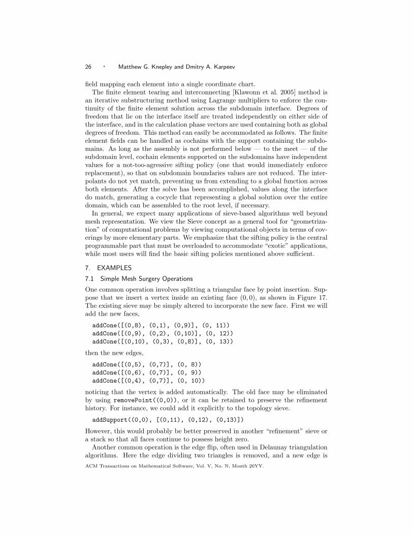
field mapping each element into a single coordinate chart.The finite element tearing and interconnecting [Klawonn et al. 2005] method is
an iterative substructuring method using Lagrange multipliers to enforce the con-tinuity of the finite element solution across the subdomain interface. Degrees offreedom that lie on the interface itself are treated independently on either side ofthe interface, and in the calculation phase vectors are used containing both as globaldegrees of freedom. This method can easily be accommodated as follows. The finiteelement fields can be handled as cochains with the support containing the subdo-mains. As long as the assembly is not performed below — to the meet — of thesubdomain level, cochain elements supported on the subdomains have independentvalues for a not-too-agressive sifting policy (one that would immediately enforcereplacement), so that on subdomain boundaries values are not reduced. The inter-polants do not yet match, preventing us from extending to a global function acrossboth elements. After the solve has been accomplished, values along the interfacedo match, generating a cocycle that representing a global solution over the entiredomain, which can be assembled to the root level, if necessary.
In general, we expect many applications of sieve-based algorithms well beyondmesh representation. We view the Sieve concept as a general tool for “geometriza-tion” of computational problems by viewing computational objects in terms of cov-erings by more elementary parts. We emphasize that the sifting policy is the centralprogrammable part that must be overloaded to accommodate “exotic” applications,while most users will find the basic sifting policies mentioned above sufficient.
7. EXAMPLES
7.1 Simple Mesh Surgery Operations
One common operation involves splitting a triangular face by point insertion. Sup-pose that we insert a vertex inside an existing face (0, 0), as shown in Figure 17.The existing sieve may be simply altered to incorporate the new face. First we willadd the new faces,
addCone([(0,8), (0,1), (0,9)], (0, 11))addCone([(0,9), (0,2), (0,10)], (0, 12))addCone([(0,10), (0,3), (0,8)], (0, 13))
then the new edges,
addCone([(0,5), (0,7)], (0, 8))addCone([(0,6), (0,7)], (0, 9))addCone([(0,4), (0,7)], (0, 10))
noticing that the vertex is added automatically. The old face may be eliminatedby using removePoint((0,0)), or it can be retained to preserve the refinementhistory. For instance, we could add it explicitly to the topology sieve.
addSupport((0,0), [(0,11), (0,12), (0,13)])
However, this would probably be better preserved in another “refinement” sieve ora stack so that all faces continue to possess height zero.
Another common operation is the edge flip, often used in Delaunay triangulationalgorithms. Here the edge dividing two triangles is removed, and a new edge isACM Transactions on Mathematical Software, Vol. V, No. N, Month 20YY.

Flexible Representation of Computational Meshes · 27
(0,5)
(0,11)
(0,4)
(0,6)
(0,3)
(0,2) (0,1)
(0,13)
(0,10)
(0,9)
(0,8)
(0,7)
(0,12)
(0,0)
Fig. 17. Point insertion into a triangular face.
inserted joining the opposite vertices, as shown in Figure 18. Two operations onthe sieve are necessary to perform the flip. First, the cone of the flipped edgebecomes the two opposite vertices of the quadrangle, in this case (0,7) and (0,10).Next, the triangle cones must swap a pair of opposite edges. In this case we choose(0,3) and (0,6). If we had chosen the other pair,(0,2) and (0,5), it would merelyhave placed (0,0) on the bottom. This latter change is more easily carried out byadding and deleting the individual arrows rather than by setting whole cones.
7.2 Constructing the Dual Graph
An example illustrating the power and simplicity of the Sieve construct is the forma-tion of the essential part of a dual mesh, or element connectivity graph, in parallel.This is typically required to compute a mesh partition by using graph partitioningalgorithms such as those implemented in ParMetis [Karypis et al. 2005]. Consideragain the doublet mesh divided between two processes, shown in Figure 2. As evi-dent from the serial sieve on the left of Figure 2, the two simplices (0,10) and (0,11)are adjacent as they share the edge (0, 7). In the partitioned sieve on the right,however, this determination cannot be made on either process separately.
To make the adjacency determination in parallel, we use the support completionoperation. We use only the part of the parallel doublet mesh sieve from Figure 2(right) representing edges and triangles, which is sufficient for triangle adjacencydetermination. Clearly the local support for (0, 3) contains a single element. How-ever, we can use supportCompletion and add to construct the completed sieveon each process, shown at the top of Figure 19; the completion portion is dashed.Both processes now contain the two triangles (0,6) and (1,5) covered by a singleedge (0, 5). The edge separates adjacent triangles, and this fact is recorded in thetriangle adjacency graph, illustrated at the bottom of Figure 19. This process canbe carried out for any mesh, producing the triangle connectivity graph. Othertypes of connectivity data structures can be computed in an analogous manner. In
ACM Transactions on Mathematical Software, Vol. V, No. N, Month 20YY.

28 · Matthew G. Knepley and Dmitry A. Karpeev
(0,2) (0,3) (0,5) (0,6)
(0,7) (0,10)
(0,0) (0,1)
(0,4)
(0,8) (0,9)
(0,1)(0,0)
(0,2)
(0,3)(0,4) (0,5)
(0,6)
(0,7)
(0,8)
(0,9)
(0,10)
(0,2) (0,3) (0,5) (0,6)
(0,7) (0,10)
(0,0) (0,1)
(0,4)
(0,8) (0,9)
(0,2)
(0,3) (0,5)
(0,6)
(0,7)
(0,8)
(0,9)
(0,10)
(0,1)
(0,0)(0,4)
Fig. 18. Edge (0,4) is flipped.
ACM Transactions on Mathematical Software, Vol. V, No. N, Month 20YY.

Flexible Representation of Computational Meshes · 29
0,6
0,4 0,50,3 1,3 1,40,5
process 0 process 1
process 0 process 1
0,6
� �� �� �
� �� �� �
1,5
� �� �� �
� �� �� �
1,5
� �� �� �
� �� �� �
0,6
� �� �� �
� �� �� �
0,6 1,5
1,5
Fig. 19. One stage in the construction of a mesh connectivity graph from a (partial) distributed
mesh sieve. Without completion, adjacency of nodes (0,6) and (1,5) cannot be derived.
dualTopology = ALE.Sieve.Sieve()
dualTopology.setComm(comm)
completion, footprint = topology.supportCompletion(footprintTypeSupport)
for face in topology.heightStratum(1):
support = topology.support(face)
if len(support) == 2:
dualTopology.addCone(support, face)
elif len(support) == 1 and completion.capContains(face):
dualTopology.addCone((support[0], completion.support(face)[0]), face)
Fig. 20. Python code to create the dual mesh.
particular, using completion methods we can compute the dual mesh with an edgebetween the two members of any face with support of size two.8 Figure 20 containsPython code to construct the dual mesh. Notice that no part of this code refers tothe dimension of the mesh or any element, or to the shape or connectivity of anyelement, and thus will work for any general mesh.
7.3 Partitioning in Parallel
Since partitions are merely collection of mesh elements, we may view a partitionas covered by the elements it contains, and thus enlarge our sieve to include thepartitions themselves. The cone of each partition point is now the set of elementsin that partition. Using this construction, we may redistribute the mesh using onlythe cone completion operation.
First we consider the case of distributing a serial mesh that has been partitioned.The initial process will contain the full mesh sieve and an assignment of elementsto processes in a partition sieve. The other processes will add the partition nodecorresponding to that process, for example, the prefix given by the size of thecommunicator and index by the process rank as in the top diagram of Figure 21.
8Recall that in a mesh sieve each cell of codimension 1 can be shared by at most two other cells.
ACM Transactions on Mathematical Software, Vol. V, No. N, Month 20YY.

30 · Matthew G. Knepley and Dmitry A. Karpeev
process 1process 0
process 0 process 1
2,1
1,3 1,40,3 0,4 0,5 0,6 1,5
0,30,1 0,2 1,41,30,50,41,1 1,2
2,12,0
0,1 0,2 1,1 1,2 1,41,30,50,3 0,4 0,6 1,5
P
T
process 1process 0
process 0 process 1
1,21,10,2 0,5 1,51,3 1,40,3 0,4 0,5 0,6 1,5
0,30,1 0,2 1,41,30,50,41,1 1,2
2,12,0
0,1 0,2 1,1 1,2 1,41,30,50,3 0,4 0,6 1,5
2,1
� �� �� �
� �� �� �1,1 � �
� �� �
� �� �� �1,5� � �
� � �� � �
� � �� � �� � �
� �� �� �
� �� �� �
� �� �� �
� � �� � �� � �
� �� �� �
P
T
1,3 1,4
1,2 1,3 1,40,2 0,5
process 1process 0
process 0 process 1
1,41,3
1,21,10,2 0,5 1,5
0,51,1 1,20,2
2,1
1,3 1,40,3 0,4 0,5
0,1 0,50,4
2,12,0
0,1 0,2 1,1 1,2 1,41,30,50,3 0,4 0,6 1,5
1,1
P
T
1,3 1,4
1,2 1,3 1,40,2 0,51,1 1,5
0,30,2
0,6
Fig. 21. Three states of sieves involved in doublet mesh partitioning. Initial state of the parti-tioning (P) and the topology (T) sieves (top); after completion of P (middle); after completion of
T (bottom).
ACM Transactions on Mathematical Software, Vol. V, No. N, Month 20YY.

Flexible Representation of Computational Meshes · 31
completion, footprint = topology.coneCompletion(footprintTypeCone)
topology.add(completion)
for point in topology.cone((-1, rank)):
topology.addBasePoint(point)
completion, footprint = topology.coneCompletion(footprintTypeCone)
topology.add(completion)
topology.restrictBase(topology.cone((-1, rank)))
Fig. 22. Python code to partition a mesh
In the case of the doublet mesh used in the figure, it is sufficient to partition thetriangles — elements of highest dimension — into disjoint sets corresponding toprocesses. Then all of the covering elements of each triangle are added to thecorresponding set, possibly duplicating lower order elements on different processes.Such a partitioning strategy is sufficient to retain all information about a serialsieve after its distribution.
After the initial setup, cone completion will transfer the entire cone of each par-tition element to the remaining processes. This completion consists of all elementsin that partition and is merged into the sieve (see middle diagrams in Figure 21);on all processes other than root, the cap of the completed sieve is a duplicate ofthe base of the topology sieve. A second completion will transfer all the cover-ing relations to the other processes. Finally, the local sieve on the root process ispruned of all elements whose support does not contain its partition element (seethe bottom diagrams in Figure 21). In the case of fully parallel rebalancing, eachprocess creates partition nodes and cones exactly as the first process in the serialcase, and then the partitioning proceeds exactly as in the serial case. Notice thatthe code in Figure 22 is again independent of dimension and element connectivity.
Upon cone completion, the full topology will be available on all processes; how-ever, the element ownership will still appear as it was prior to the partition. We canrenumber the elements to reflect the partition by completing the sieve once more,thereby putting all shared elements into the completion. Then a simple tie-breakingrule can be used to divide up shared elements. This method will be used to createvariable numberings in Section 7.5; however, element identity is immaterial for thisso we will not bother to carry it out.
7.4 Meshing in Parallel
The strategy for meshing in parallel is now similar to that for partitioning. Weuse a serial mesh generator to generate a mesh on each individual process, usingan initial boundary communicated to all processes. These meshes may disagree onthe boundary; however, we will construct a cover of the original edges by any edgesproduced by splitting. Then, using cone completion, we can construct a completecovering of the boundary. We must then resolve incommensurate coverings of eachboundary edge either by merging two close points or by introducing another edgebetween the two. Any newly introduced boundary edges are incorporated into theexisting process mesh. As a final step, we may run a parallel mesh improvementalgorithm, without topology change, to smooth out any distortions caused by merg-ing [Munson 2004]. This procedure will result in a mesh that may be artificially
ACM Transactions on Mathematical Software, Vol. V, No. N, Month 20YY.

32 · Matthew G. Knepley and Dmitry A. Karpeev
refined along process boundaries, but this effect becomes negligible as the meshgrows, and we argue that it is far outweighed by the simplicity of the algorithmitself.
We also note that a serial mesh generator can be used to construct periodicmeshes. Just as in the parallel mesh example, we must merge a boundary, in thiscase the identified periodic boundary. This merge is accomplished in exactly thesame manner, resulting in a fully periodic mesh.
7.5 Constructing a Finite Element
We have remarked above that the restriction and prolongation operations are ex-actly the mechanism responsible for finite element assembly. Here we demonstratethis in detail for a higher-order Lagrange element on multiple fields. The restric-tion of a continuum field to an element T is what we approximate using our finiteelement space P . For our Lagrange element, we use a nodal basis, meaning thatthe basis {φi} for P and the basis of functionals {Lj} for its dual P ′ satisfy
Lj(φi) = δij .
Thus, the restriction process can be thought of as a selection of the coefficientsfor basis functions in P that are nonvanishing on T , and each coefficient can beidentified with the particular Lj which does not annihilate that basis function.Furthermore, each Lj is identified with a certain topological piece of the element.In the case of point evaluations, this is merely the piece on which the evaluationpoint occurs.
Consider the third-order Lagrange element on a triangle. In Figure 23, the circlesrepresent the point evaluation functionals that form a basis for P ′. If we, forinstance, restrict to e2, then we will require the four coefficients associated with(v0, v1, e2). Restricting to T , we need the coefficients from all the labeled topologicalelements, which we can recognize from above as the cone of f0.
In traditional finite element code, one represents the discretized field by an arrayof basis function coefficients. This approach forces the user to construct a number-ing on the basis functions and then select the correct indices for each element. Thus,the code is more complicated, and its relation to the mathematics is obfuscated.In our paradigm, we replace the integers in indexing with the topological elementsthemselves, and selection occurs through the cone construction. In addition, whenwe consider the problem of representing multiple discrete fields over the mesh, werealize the full power of the stack as lattice operations are incorporated. We canrepresent degrees of freedom as points in a discrete sieve (i.e., a sieve without ar-rows). Variables may be associated with topological elements by vertical arrowswith the topology as the base. However, we would like a mechanism to segregatevariables in each field. Each field is represented by a point in an auxiliary sieve,which is then used as the base of a stack whose vertical arrows connect to the degreeof freedom sieve. The cone over each field point is the set of variables in the field,as depicted in Figure 24, and the degrees of freedom from a given field over a givenelement are simply the meet of the cones in the corresponding base points. Thisapproach also allows us to order the degrees of freedom in a manner suitable fora given application, or even reorder them for different stages of the computation,without affecting the retrieval code.ACM Transactions on Mathematical Software, Vol. V, No. N, Month 20YY.

Flexible Representation of Computational Meshes · 33
f_0
e_0
v_0 v_1e_2
v_2
e_1
Fig. 23. Third-order Lagrange element.
As a concrete example, we create a numbering for two fields over the doubletmesh. The first is a P2 vector field and the second a P3 scalar field. Figure 25shows these initial choices and the creation of the numbering stack. In Figure 27we present the numbering algorithm itself.
We loop over all elements in the topology. If the element is present on morethan one process, only the lowest-rank process will create degrees of freedom overit. We then loop over each field and decide how many degrees of freedom the fieldpossesses on that element. FIAT can provide the size of the dual space on anelement of that dimension, and we equate dimension with depth in the sieve. Weassume that tensor fields have dimension equal to the dimension of the mesh. Weadd these new degrees of freedom to the cone of the current field and then addthe collective degrees of freedom for the current element to its vertical cone in thenumbering stack. Lastly, the stack is completed over vertical arrows so that ghostdegrees of freedom are available. The full stack is shown in Figure 26.
If we let f and K be the local element vector and matrix, F a global discretefield, and J its Jacobian, the code in Figure 28 will assemble the function and itsJacobian.
Using both sieves and stacks, we have provided routines that partition a meshin parallel, calculate the finite element variable ordering, integrate the weak form,
ACM Transactions on Mathematical Software, Vol. V, No. N, Month 20YY.

34 · Matthew G. Knepley and Dmitry A. Karpeev
���������������������������������������������������������������������������������������������������������������������������������������������������������������������������������������������������������������������������������������������������������������������������������������������������������������������������������������������������������������������������������������������������������������������������������������������������������������������������������������������������������������������������������������������������������������������������������������������������������������������������������������������������������������������������������������
���������������������������������������������������������������������������������������������������������������������������������������������������������������������������������������������������������������������������������������������������������������������������������������������������������������������������������������������������������������������������������������������������������������������������������������������������������������������������������������������������������������������������������������������������������������������������������������������������������������������������������������������������������������������������������������
�������������������������������������������������������������������������������������������������������������������������������������������������������������������������������������������������������������������������������������������������������������������������������������������������������������������������������������������������������������������������������������������������������������������������������������������������������������������������������������������������������������������������������������������������������������������������������������������������������������������
�������������������������������������������������������������������������������������������������������������������������������������������������������������������������������������������������������������������������������������������������������������������������������������������������������������������������������������������������������������������������������������������������������������������������������������������������������������������������������������������������������������������������������������������������������������������������������������������������������������������
Topology
DOFs
Fields
Fig. 24. Degrees of freedom for multiple fields.
elements = [FIAT.Lagrange.Lagrange(FIAT.shapes.TRIANGLE, 2),
FIAT.Lagrange.Lagrange(FIAT.shapes.TRIANGLE, 3)]
ranks = [1, 0]
dim = mesh.getDimension()
dof = ALE.Sieve.Sieve()
dof.setComm(comm)
numbering = ALE.Stack.Stack()
numbering.setComm(comm)
numbering.setTop(dof)
numbering.setBottom(topology)
Fig. 25. Initial specifications for the finite elements.
and assemble the operator. These routines are independent of the mesh dimension,global topology, element shapes, and finite element.
8. CONCLUSIONS
A key conclusion of this effort is that better mathematical abstractions in softwarebring concrete benefits. In current FEM simulation packages, reusability rarelygoes beyond the linear algebra level. The reason is a lack of effective mathemati-cal abstractions for hierarchically structured data and operations that adequatelyreflect the modeled problem. Components cannot be shared when operations areinextricably linked in the implementation. Furthermore, the complexity of the ex-isting hierarchical solvers written without the benefit of these abstractions increasesquickly, creating inpenetrable and unmaintainable code. This low-level approachACM Transactions on Mathematical Software, Vol. V, No. N, Month 20YY.

Flexible Representation of Computational Meshes · 35
1 2 5 8 10
1514 17 20 21 24
1211
2825
3334
4 6 7 9
16 0,1
0,6 0,7
0,10 0,11
0,8 0,90,5
29 30 31
0,0
0,2 0,3 0,4
3
32
18 19 22 23 26 27
13
edges
vertices
triangles
local sieve
Fig. 26. DOF stack for the trial discretization over a doublet mesh.
completion, footprint = topology.supportCompletion(footprintTypeSupport)
index = 0
for p in topology.space():
if completion.capContains(p):
neighbors = footprint.support([p]+list(completion.support(p)))
if [0 for processTie in neighbors if processTie[1] < rank]:
continue
indices = []
for field in range(len(elements)):
scalarDof = len(elements[field].dual_basis().getNodeIDs(topology.depth(p))[0])
entityDof = scalarDof*max(1, dim*ranks[field])
if entityDof:
var = [(-(rank+1), index+i) for i in range(entityDof)]
indices.extend(var)
index += entityDof
dof.addCone(var, (0, field))
numbering.addCone(indices, p)
completion, footprint = numbering.coneCompletion(footprintTypeCone)
Fig. 27. Python code to create a variable ordering.
to implementation has also greatly hindered generalization of these algorithms, forinstance to regions with nontrivial global topology.
However, many of these difficulties can be rectified by using the Sieve constructand sieved array structures. Discarding the explicit dimensionality and shape in-formation in the algorithms not only reduces the complexity but also results inmuch greater generality. All operations are expressed in terms of a single cover-ing relation, which captures the ubiquitous notion of a decomposition of objectsinto more elementary parts. With only a single routine with parallel communi-cation, optimization and portability also become much easier. Furthermore, sincethis approach assumes much less about the structure of the problem, sieves can bemore easily incorporated into existing PDE frameworks, and perhaps frameworks
ACM Transactions on Mathematical Software, Vol. V, No. N, Month 20YY.

36 · Matthew G. Knepley and Dmitry A. Karpeev
elements = mesh.topology.space()
elemU = u.restrict(elements)
# Loop over highest dimensional elements
for element in mesh.topology.heightStratum(0):
# We want values over the element’s closure
coeffs = elemU.getValues([element])
# Calculate the stiffness matrix and load vector
K, f = self.integrate(coeffs, self.jacobian(element, mesh, space))
# Place results in global storage
elemF.setValues([element], f)
elemJ.setValues([[element], [element]], K)
F = elemF.assemble([])
J = elemJ.assemble([])
Fig. 28. Python code to assemble the linear system. The sifting policy identifies elements with
their closures, and local matrix indexing is treated as block diagonal. Empty chain signifiestotalSieve for assembly purposes.
for other problems as well. Moreover, the generality of the interface enhances thecapabilities of existing PDE solvers. Sieves can seamlessly handle hybrid meshes,complicated global topologies as in micromagnetics, and intricate structures em-bedded in the mesh such as fault systems in seismic modeling.
Glossary
chain: A set of sieve points, often identified with a set of topological meshelements.cochain: A set of points in a dual sieve, often identified with a set of functionsover toplogical mesh elements.cocycle: A cochain satisfying consistency conditions on the meet of the elements,often identified with the agreement along element intersections of functions de-fined on the elements.covering: A relation between two sieve points, expressed by a sieve arrow. Thenotion can be extended to a relation between two chains.complete covering: A chain covering another that, for each member of thecovered chain, includes either that member or its entire cone.localSieve: An artificial sieve point covered by all of the leaves on the process.sieve: A directed acyclic graph that expresses a covering relation between points,meant to encode an etale topology.stack: A sieve that has other sieves for both its cap and base. Sieve operationsoperate only over arrows between these sieves, not inside them.sieved array: Storage structured according to the covering relations of a sieve.totalSieve: An artificial sieve point covered by all of the leaves in the sieve.
ACKNOWLEDGMENTS
We thank Barry Smith for many helpful discussions and suggestions for improvingthe paper; Robert Kirby for careful readings of the drafts; and Gail Pieper for a veryACM Transactions on Mathematical Software, Vol. V, No. N, Month 20YY.

Flexible Representation of Computational Meshes · 37
thorough reading of the draft. This work was supported in part by the Mathemat-ical, Information, and Computational Sciences Division subprogram of the Officeof Advanced Scientific Computing Research, Office of Science, U.S. Department ofEnergy, under Contract W-31-109-ENG-38.
REFERENCES
Aleksandrov, P. 1957. Combinatorial Topology. Graylock Press, Rochester, N.Y.
Balay, S., Buschelman, K., Eijkhout, V., Gropp, W. D., Kaushik, D., Knepley, M. G.,
McInnes, L. C., Smith, B. F., and Zhang, H. 2005. PETSc Web page. http://www.mcs.anl.
gov/petsc.
Barr, M. and Wells, C. 1985. Toposes, Triples and Theories. Springer, Berlin.
Brisson, E. 1989. Representing geometric structures in d dimensions: Topology and order. In
SCG ’89: Proceedings of the Fifth Annual Symposium on Computational Geometry. ACM
Press, New York, 218–227.
Brown, D., Glimm, J., and Freitag, L. 2005. Terascale Simulation Tools and Technology(TSTT) Center. http://www.tstt-scidac.org.
Chung, F., Andersen, R., and Lu, L. 2004. Drawing power law graphs. In 12th International
Symposium on Graph Drawing.
Ciarlet, P. 1978. The Finite Element Method for Elliptic Problems. North-Holland.
Dupont, T., Hoffman, J., Jansson, J., Johnson, C., Kirby, R. C., Knepley, M., Larson, M.,Logg, A., and Scott, R. 2005. FENICS Web Page. http://www.fenics.org.
Fitch et.al., B. G. 2005. Blue matter: Strong scaling of molecular dynamics on BlueGene/L.
Research Report W0508-035, IBM Research. August.
Karypis et al., G. 2005. ParMETIS Web page. http://www.cs.umn.edu/~karypis/metis/
parmetis.
Kirby, R. C. 2004. Algorithm 839: FIAT: A new paradigm for computing finite element basis
function. ACM Transactions on Mathematical Software 30, 4 (Dec.), 502–516.
Kirby, R. C. 2006. Optimizing FIAT with Level 3 BLAS. ACM Transactions on Mathematical
Software.
Klawonn, A., Rheinbach, O., and Widlund, O. B. 2005. Some computational results for dual-
primal feti methods for three dimensional elliptic problems. In Domain Decomposition Methods
in Science and Engineering, R. Kornhuber et.al., Ed. Lect. Notes Comput. Sci. Eng., vol. 40.Springer, Berlin, Germany, 361–368.
Knepley, M. and Karpeev, D. 2006. A categorial approach to computational meshes. in
preparation.
Knepley et al., M. 2005. Argonne SIDL Environment Web page. http://www.mcs.anl.gov/ase.
MPI Forum. 2005. MPI forum home page. http://www.mpi.org.
Munson, T. 2004. Mesh shape-quality optimization using the inverse mean-ratio metric. PreprintANL/MCS-P1136-0304, Argonne National Laboratory. April.
Shewchuk, J. 2005. Triangle: A Two-Dimensional Quality Mesh Generator and Delaunay Trian-
gulator. http://www-2.cs.cmu.edu/~quake/triangle.html.
Si, H. 2005. TetGen: A Quality Tetrahedral Mesh Generator and Three-Dimensional DelaunayTriangulator. http://tetgen.berlios.de.
ACM Transactions on Mathematical Software, Vol. V, No. N, Month 20YY.

38 · Matthew G. Knepley and Dmitry A. Karpeev
The submitted manuscript has been created bythe University of Chicago as Operator of ArgonneNational Laboratory (”Argonne”) under ContractNo. W-31-109-ENG-38 with the U.S. Departmentof Energy. The U.S. Government retains for itself,and others acting on its behalf, a paid-up, nonex-clusive, irrevocable worldwide license in said ar-ticle to reproduce, prepare derivative works, dis-tribute copies to the public, and perform publiclyand display publicly, by or on behalf of the Gov-ernment.
ACM Transactions on Mathematical Software, Vol. V, No. N, Month 20YY.