Sedimentological processes in a scarp-controlled rocky shoreline to upper continental slope...
26
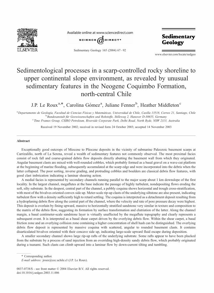
Sedimentological processes in a scarp-controlled rocky shoreline to upper continental slope environment, as revealed by unusual sedimentary features in the Neogene Coquimbo Formation, north-central Chile J.P. Le Roux a, * , Carolina Go ´mez a , Juliane Fenner b , Heather Middleton c a Departamento de Geologı `a, Facultad de Ciencias Fı `sicas y Matema ´ticas, Universidad de Chile, Casilla 13518, Correo 21, Santiago, Chile b Bundesanstalt fu ¨r Geowissenschaften und Rohstoffe, Stilleweg 2, Hanover D-30655, Germany c Time Frames Group, CSIRO Petroleum, Riverside Corporate Park, Delhi Road, North Ryde, NSW 2113, Australia Received 19 November 2002; received in revised form 24 October 2003; accepted 14 November 2003 Abstract Exceptionally good outcrops of Miocene to Pliocene deposits in the vicinity of submarine Paleozoic basement scarps at Carrizalillo, north of La Serena, reveal a wealth of sedimentary features not commonly observed. The most proximal facies consist of rock fall and coarse-grained debris flow deposits directly abutting the basement wall from which they originated. Angular basement clasts are mixed with well-rounded cobbles, which probably formed as a basal gravel on a wave-cut platform at the beginning of marine flooding, subsequently accumulated at the scarp edge and were incorporated into the debris when the latter collapsed. The poor sorting, inverse grading, and protruding cobbles and boulders are classical debris flow features, with good clast imbrication indicating a laminar shearing action. A medial facies is represented by secondary channels running parallel to the major scarp about 1 km downslope of the first locality. In the largest channel, megaflutes at the base indicate the passage of highly turbulent, nondepositing flows eroding the soft, silty substrate. In the deepest, central part of the channel, a pebbly coquina shows horizontal and trough cross-stratification, with most of the bivalves oriented convex side up. Meter-scale rip-up clasts of the underlying siltstone are also present, indicating turbulent flow with a density sufficiently high to retard settling. The coquina is interpreted as a detachment deposit resulting from a hydroplaning debris flow along the central part of the channel, where the velocity and rate of pore pressure decay were highest. This deposit is overlain by fining upward, massive to horizontally stratified sandstone very similar in texture and composition to the matrix of the debris flow, suggesting its formation by surface transformation and elutriation of the latter. Along the channel margin, a basal centimeter-scale sandstone layer is virtually unaffected by the megaflute topography and clearly represents a subsequent event. It is interpreted as a basal shear carpet driven by the overlying debris flow. Within the shear carpet, a basal friction zone and an overlying collision zone containing a higher concentration of shell hash can be distinguished. The overlying debris flow deposit is represented by massive coquina with scattered, angular to rounded basement clasts. It contains disarticulated bivalves oriented with their concave side up, indicating large-scale upward fluid escape during deposition. A smaller secondary channel shows large rip-up rafts of the underlying substrate. Some rafts appear to have been plucked from the substrate by a process of sand injection from an overriding high-density sandy debris flow, which probably originated during a tsunami. Such clasts can climb upward into a laminar flow by down-current tilting and tumbling. 0037-0738/$ - see front matter D 2004 Elsevier B.V. All rights reserved. doi:10.1016/j.sedgeo.2003.11.006 * Corresponding author. E-mail address: [email protected] (J.P. Le Roux). www.elsevier.com/locate/sedgeo Sedimentary Geology 165 (2004) 67 – 92
-
Upload
independent -
Category
Documents
-
view
1 -
download
0
Transcript of Sedimentological processes in a scarp-controlled rocky shoreline to upper continental slope...
www.elsevier.com/locate/sedgeo
Sedimentary Geology 165 (2004) 67–92
Sedimentological processes in a scarp-controlled rocky shoreline to
upper continental slope environment, as revealed by unusual
sedimentary features in the Neogene Coquimbo Formation,
north-central Chile
J.P. Le Rouxa,*, Carolina Gomeza, Juliane Fennerb, Heather Middletonc
aDepartamento de Geologıa, Facultad de Ciencias Fısicas y Matematicas, Universidad de Chile, Casilla 13518, Correo 21, Santiago, ChilebBundesanstalt fur Geowissenschaften und Rohstoffe, Stilleweg 2, Hanover D-30655, Germany
cTime Frames Group, CSIRO Petroleum, Riverside Corporate Park, Delhi Road, North Ryde, NSW 2113, Australia
Received 19 November 2002; received in revised form 24 October 2003; accepted 14 November 2003
Abstract
Exceptionally good outcrops of Miocene to Pliocene deposits in the vicinity of submarine Paleozoic basement scarps at
Carrizalillo, north of La Serena, reveal a wealth of sedimentary features not commonly observed. The most proximal facies
consist of rock fall and coarse-grained debris flow deposits directly abutting the basement wall from which they originated.
Angular basement clasts are mixed with well-rounded cobbles, which probably formed as a basal gravel on a wave-cut platform
at the beginning of marine flooding, subsequently accumulated at the scarp edge and were incorporated into the debris when the
latter collapsed. The poor sorting, inverse grading, and protruding cobbles and boulders are classical debris flow features, with
good clast imbrication indicating a laminar shearing action.
A medial facies is represented by secondary channels running parallel to the major scarp about 1 km downslope of the first
locality. In the largest channel, megaflutes at the base indicate the passage of highly turbulent, nondepositing flows eroding the
soft, silty substrate. In the deepest, central part of the channel, a pebbly coquina shows horizontal and trough cross-stratification,
with most of the bivalves oriented convex side up. Meter-scale rip-up clasts of the underlying siltstone are also present, indicating
turbulent flow with a density sufficiently high to retard settling. The coquina is interpreted as a detachment deposit resulting from
a hydroplaning debris flow along the central part of the channel, where the velocity and rate of pore pressure decay were highest.
This deposit is overlain by fining upward, massive to horizontally stratified sandstone very similar in texture and composition to
the matrix of the debris flow, suggesting its formation by surface transformation and elutriation of the latter. Along the channel
margin, a basal centimeter-scale sandstone layer is virtually unaffected by the megaflute topography and clearly represents a
subsequent event. It is interpreted as a basal shear carpet driven by the overlying debris flow. Within the shear carpet, a basal
friction zone and an overlying collision zone containing a higher concentration of shell hash can be distinguished. The overlying
debris flow deposit is represented by massive coquina with scattered, angular to rounded basement clasts. It contains
disarticulated bivalves oriented with their concave side up, indicating large-scale upward fluid escape during deposition.
A smaller secondary channel shows large rip-up rafts of the underlying substrate. Some rafts appear to have been plucked
from the substrate by a process of sand injection from an overriding high-density sandy debris flow, which probably originated
during a tsunami. Such clasts can climb upward into a laminar flow by down-current tilting and tumbling.
0037-0738/$ - see front matter D 2004 Elsevier B.V. All rights reserved.
doi:10.1016/j.sedgeo.2003.11.006
* Corresponding author.
E-mail address: [email protected] (J.P. Le Roux).

J.P. Le Roux et al. / Sedimentary Geology 165 (2004) 67–9268
The most distal facies occurs below a second scarp oriented more or less parallel to the present coastline, where finer-grained
turbidites onlap and backlap onto the stoss and lee sides of an obstacle formed by eroded boulder conglomerates. The onlap
deposits resemble inclined sandy macroforms recently described in submarine canyon settings. They are interbedded with
diatom-containing, volcanic ash beds with cross-stratification dipping eastwards and containing deepwater microflora typical of
continental upwelling zones.
D 2004 Elsevier B.V. All rights reserved.
Keywords: Coastal sedimentation; Submarine canyon; Continental shelf; Continental slope; Debris flow; Turbidite
1. Introduction 100-m topographic and bathymetric contours and
One of the least studied and most complex sedi-
mentary environments is that of rocky shorelines
(Felton, 2002). This environment is bounded by the
Fig. 1. Map indicating location of study area (small square north of La
described in text. The direction of transport as derived from channel trend
(n= 44).
occurs preferentially in tectonically active settings
(e.g., on the narrow shelves of active continental
margins). Typical geomorphic features are terraces
and cliffs transected by canyons, where erosional
Serena on inset of South America), as well as places and outcrops
s, cross-lamination, and flute casts is indicated in the rose diagram

J.P. Le Roux et al. / Sedimentary Geology 165 (2004) 67–92 69
and depositional agents such as waves, ocean currents,
gravity flows, and tsunamis are dominant (Felton,
2002). In this paper, we describe Miocene–Pliocene
deposits of the Coquimbo Formation in a remote
section of the Chilean coast some 80 km north of
La Serena (Fig. 1), which are attributed partly to this
environment. Exceptionally good exposures along
Quebrada Chanaral to the north of the hamlet Carri-
zalillo exhibit a wealth of sedimentary features that we
interpret in the light of various transport and deposi-
tional processes. This provides some new insights into
the sedimentology of rocky shoreline and associated
environments.
2. Geologic and tectonic setting
The study area lies within a region characterised by
four topographic domains, from west to east, com-
prising the Coastal Plain, Coastal Range, Central
Depression, and Andean Range. Basement rocks, onto
which the Coquimbo Formation was deposited direct-
ly, are represented by the Paleozoic Coastal Metamor-
phites, a metasedimentary succession underlying most
of the Coastal Plain.
The region falls within the Chilean flat-slab zone
between about 26jS and 33jS (Pardo et al., 2002).
Le Roux et al. (in press) studied the tectonic
history of the area during the Miocene–Pliocene
using paleobathymetry, backstripping, and dating of
the stratigraphic units based on Sr isotopes as well
as microfossils and macrofossils. They concluded
that the area underwent strong subsidence during
the late Burdigalian–early Langhian, which caused
marine transgression to continental shelf depths
over the coastal basement platform. The subsequent
approach and subduction of the Juan Fernandez
Ridge between about 13 and 8 Ma produced
tectonic uplift, but not sufficient to elevate the shelf
above the contemporaneous sea level. Renewed
submergence of the shelf between 8 and 3 Ma in
the wake of the southeastward-migrating Juan Fer-
nandez Ridge was followed by rapid uplift, with
the shelf finally emerging above sea level during
the Quaternary.
Water depths on the shelf after the initial flooding
fluctuated between about 20 and 200 m, as indicated
by the sedimentological facies (including bored phos-
phatic hardground) and foraminifera such as Bulimina
elongata, Buliminella elegantissima, Globigerina bul-
loides, Globigerinella calida, and Globigerinita glu-
tinata. On the seaward side of a basement scarp
running parallel to the present coastline, upper conti-
nental slope sedimentation is reflected by foraminifera
such as Brizalina aenariensis, sinistrally coiled Neo-
globoquadrina pachyderma, Globorotalia inflata, and
Orbulina universa, as well as a diatom assemblage
typical of marine upwelling on the continental slope
or outer shelf, including the Thalassiosira spp. Tha-
lassiosira eccentrica, Thalassiosira oestrupii, and
Thalassiosira leptopus; Stephanopyxis spp.; as well
as Azpeitia curvatulus, Actinocyclus curvatulus, Acti-
noptychus senarius, Actinoptychus splendens, Paralia
sulcata, Thalassionema nitzschiodes, and Nitzschia
fossilis (Le Roux et al., in press). Chaetoceros resting
spores, one of the most evident signs of upwelling, are
also common.
The best exposures are encountered along three dry
river valleys or ‘‘quebradas’’ that traverse the coastal
plain in a westerly to southwesterly direction. Along
the northernmost and largest of these, Quebrada
Chanaral (Fig. 1), a variety of Miocene–Pliocene
continental shelf and associated environments can be
identified. In its upper reaches, where the quebrada
approaches the rising Coastal Range, beach conglom-
erates with wave-polished pebbles partly covered with
barnacles are associated with poorly sorted fluvial
conglomerates showing upstream-dipping imbrica-
tion. Downstream along the quebrada, these rocks
pass into typical lower shoreface deposits with inter-
bedded, bioturbated (Thalassinoides) sandstones and
shales. Rare hummocky and swaley cross-lamination
attest to deposition by storms below the fair weather
wave base.
3. Basement topography
In the study area north of Carrizalillo, the Coastal
Plain is 10–14 km wide and slopes at about 1j from
sea level to the foot of the Coastal Range, which rises
from 200 m to elevations exceeding 1000 m in places.
Le Roux et al. (in press) suggested that the Coastal
Plain mirrors the palaeotopography during the Mio-
cene, when a coastal platform was carved into the
Coastal Metamorphites. A somewhat irregular plat-

J.P. Le Roux et al. / Sedimentary Geology 165 (2004) 67–9270
form topography is shown by the presence of local
basement hillocks rising to elevations of about 200 m
above present sea level, with the surrounding plain
lying between 125 and 175 m over most of the study
area (Fig. 2). That the basement platform was at sea
level during the early Langhian is suggested by the
fact that it is overlain by large, wave-smoothed
basement boulders partly covered with Balanus sp.
on the southeastern side of Quebrada Chanaral just
southwest of Chanaral de Aceituna (Fig. 1). A unit
directly overlying the boulder bed was dated by87Sr/86Sr at 14.6 Ma (Le Roux et al., in press). Ostrea
sp., which like Balanus sp. are particular to the littoral
(Stenzel, 1944) or sublittoral zone, are also found
clinging to the rocky surface of small gullies draining
into Quebrada Chanaral.
Basement rocks crop out mostly to the area
northwest of Quebrada Chanaral, which may be
due to a major fault displacing them downward to
the southeast. Evidence indicating such a fault is
seen, for example, at locality 1 (Fig. 1), where the
basement forms a vertical to slightly overhanging
cliff striking 204j, against which the Coquimbo beds
abut sharply from the southeast. There is a 2-m-wide
sheared zone in the basement along its contact with
the Coquimbo Formation, but towards the northeast
and base of the cliff, this zone is separated from the
Coquimbo Formation by a few meters of unbrecci-
Fig. 2. Diagrammatic representation of the basement topography
ated metamorphites. As the Coquimbo Formation
itself shows no sign of shearing, it probably post-
dates the fault. This is supported by an outcrop in a
small secondary quebrada northeast of Chanaral de
Aceituna, where the Coquimbo Formation similarly
abuts against a vertical basement wall, but also
overlies a horizontal ledge within the latter without
any sign of displacement.
This SSW-striking, probably fault-controlled
scarp formed by the basement appears to have had
a major influence on sedimentation patterns during
the Miocene–Pliocene, as suggested by the deposi-
tional facies encountered in its vicinity and de-
scribed in this paper. Downstream along Quebrada
Chanaral, however, the scarp gradually changes into
a southeastward-sloping surface (Fig. 2) onlapped
towards the northwest by younger stratigraphic units
of the Coquimbo Formation. It possibly formed by
erosion of the scarp prior to the Miocene–Pliocene
sedimentation.
About 1 km from the present coastline on both
sides of Quebrada Chanaral, another 320j trending
basement scarp dipping about 50jSW (Fig. 2) sep-
arates mainly shelf deposits on its landward side
from upper continental slope deposits on its seaward
side. This scarp possibly represents an ancient shore-
line cliff that was converted into the Miocene con-
tinental shelf break after the early Langhian
(not to scale) showing the location of the submarine scarps.

J.P. Le Roux et al. / Sedimentary Geology 165 (2004) 67–92 71
transgression, with the Coquimbo beds dipping at
about 3j seaward below it and draping landward
over the platform. At the platform edge/shelf break,
the basement slopes gently towards Quebrada Cha-
naral from both sides (Fig. 2), indicating that a
valley already existed here before deposition of the
Coquimbo Formation.
The SSW-trending scarp and valley described
above have about the same strike as the present
Quebrada Chanaral, possibly indicating topographic
inheritance (Le Roux, 1994). This is confirmed by
the trends of secondary channels as well as sedimen-
tary structures such as flutes and trough cross-beds
in the vicinity of these features. A rose diagram of
44 measured directional features (Fig. 1) shows a
mean transport direction of 194j, as compared to the
218j mean trend of Quebrada Chanaral. The ba-
thymetry of the present continental shelf and slope
opposite Carrizalillo also shows that the valley con-
tinues offshore to a depth of about 4000 m, termi-
nating in what seems to be a submarine fan on the
continental slope (Bundesanstalt fur Geowissenschaf-
ten und Rohstoffe, 2001).
Water depths at the foot of the SSW-trending scarp
could have reached 50–500 m, as suggested by the
presence of sinistrally coiled N. pachyderma within
the deposits. This planktonic foraminifer is a deep-
water species that lives in the photic zone during its
juvenile stage but, on maturing, descends to depths
normally exceeding 50 m, preferably below the ther-
mocline (Be and Tolderlund, 1971; Sautter and Thu-
nell, 1991). West of the NW-trending basement scarp,
water depths were on the order of 200–500 m, as
indicated by the foraminifera and diatom species
mentioned in Section 2.
4. Facies description
Three key outcrops in the vicinity of the submarine
scarps are described in this paper. The first is located
about 1 km northeast of the Chanaral de Aceituna
homestead (Fig. 1), where the SSW-trending scarp is
beautifully exposed. South and southwest of the
homestead, the basement dips gently southeastward,
where it is overlain by deposits including several
channelised features. The largest of these forms the
second locality described here (Fig. 1). The third
exposure is located about 800 m from the mouth of
Quebrada Chanaral below the NW-trending scarp,
where inclined macroforms are developed around
obstacles formed by gravelly deposits.
4.1. Facies association A: shelly sandstone interbed-
ded with poorly sorted conglomerate
At locality 1, the Coquimbo Formation dips 28jtowards the southeast against the basement scarp, but
flattens out rapidly away from the cliff (Fig. 3). A
total thickness of 35 m of deposits was measured (Fig.
4), representing the minimum height from the top of
the scarp to the basement floor (which is not exposed).
The platform edge here lies at an elevation of 150 m
above present sea level.
The age of the exposed succession is uncertain, but
it lies below unit S4 at locality 2 (Fig. 4), which field
relationships indicate is older than another unit dated
by 87S/86Sr at 5.6 Ma (Le Roux et al., in press). A
maximum age of 11 Ma is given by the presence of
the foraminifer N. pachyderma (which made its first
appearance in the Tortonian) at the base of the
succession.
4.1.1. Facies A1: shelly sandstone (biocalcarenite)
with lenses of coquina
More than 6 m of shelly sandstones (S1 in Fig.
4) are exposed below the first conglomerate (C1),
whereas the thickest conglomerates (C3/C4) are
overlain by about 8 m of similar deposits (S2).
These consist of brownish yellow, generally fine-
grained, poorly consolidated sandstone with frag-
mented to whole shells dominated by oysters
(Ostrea sp.) and pecten (Chlamys sp.). The frag-
ments are oriented parallel to the horizontal lami-
nation, except around fallen basement blocks where
they assume an orientation parallel to the sides of
the latter. Lenticular beds of coquina with larger
fragments and occasionally whole shells of oysters,
pecten, and barnacles (Balanus sp.) occur within
the shelly sandstone. Although the larger shell
fragments are parallel to the bedding, they show
no preferred convex-up or convex-down orientation.
The coquina lenses generally display irregular,
sharp basal contacts and also contain angular base-
ment clasts mostly less than 5 cm but up to 40 cm
in diameter. Towards the top of the measured

Fig. 3. View, looking NW, of scarp wall (basement) at locality 1, with biocalcarenites and coquina (S1–S3; light-coloured deposits at base of
cliff), as well as rock fall and debris flow conglomerates (C1–C5; dark deposits containing boulders and clasts). Human figure (encircled) for
scale (see also Fig. 4).
J.P. Le Roux et al. / Sedimentary Geology 165 (2004) 67–9272
succession, there are more bivalves and gastropods,
including Turritella sp. The foraminifera Textularia
gramen, G. bulloides, and the sinistral form of N.
pachyderma were identified within these deposits.
4.1.2. Facies A2: poorly sorted conglomerate
The lowermost conglomerate (C1) forms lenses up
to 30 cm thick and consists of very poorly sorted,
closely packed, angular to subangular basement clasts
that grade laterally into openwork debris. Isolated,
angular boulders or cobble clusters are present along
the same horizon, protruding into the overlying co-
quina. Towards the south, obliquely away from the
basement wall, this deposit cuts down into the under-
lying units at a low angle. Where the basement clasts
disappear in the same direction, the horizon continues
as a 5-cm-thick massive sandstone with only very
small shell fragments.
The second conglomerate (C2) is separated from
C1 by 1 m of coquina with a yellow sand matrix,
similar to the coquina lenses described above. This
unit is also thin and lenticular, with small, densely
packed basement pebbles filling 20-cm-deep, 30- to
80-cm-wide pockets in the underlying coquina. It is

Fig. 4. Measured stratigraphic columns at localities 1 and 2. On the left are the deposits of facies association A, with facies association B
deposits on the right. Dotted line shows probable correlation of units. Vertical scale applies to both columns.
J.P. Le Roux et al. / Sedimentary Geology 165 (2004) 67–92 73
overlain by 20 cm of fine shelly sandstones with
scattered, larger fragments of oysters.
The first major conglomerate (C3) has a sharp,
somewhat irregular basal contact. It exceeds 7 m in
thickness near the basement cliff but pinches out
about 100 m further south, oblique to the west–
southwestward transport direction indicated by the
clast imbrication. In the northernmost section, close
to the basement wall, this unit can be divided into
three subunits (Fig. 4). At the base, against the
cliff, is a boulder conglomerate thinning rapidly to
a 160-cm-thick zone of mostly small-pebble debris
with a fine sand matrix, but with large cobbles and
boulders up to 3 m in diameter protruding into the
middle sandstone subunit. Its upper contact is
mixed gradational. The clasts are mostly angular,
but they are intermixed with well-rounded basement
cobbles. Both clast types are oriented with their
long axes dipping up to 12j towards the basement
wall and varying in orientation between 240j and
270j. The middle subunit is a normally graded,
pebbly biocalcarenite, clasts decreasing upward
from a few centimeters in diameter to less than 1
cm. The upper subunit overlies an irregularly
scoured surface and contains cobbles and boulders
(up to several meters in diameter), which are
generally angular but intermixed with well-rounded
cobbles. The clasts are imbricated and indicate
transport between 250j and 270j. The upper part
of this subunit is normally graded, with outsized
clasts protruding into the overlying, brownish yel-
low sandstone.
About 15 m south of the thickest part of the
wedge, the lower and upper subunits merge. From

J.P. Le Roux et al. / Sedimentary Geology 165 (2004) 67–9274
this point, the conglomerate to all outward appear-
ance represents a single, uninterrupted bed gradual-
ly coarsening upward from pebble debris to cobble
and boulder debris. The basal part of the conglom-
erate in this section shows steep-sided, slightly
undercut scours filled with closely packed cobbles
and boulders (Fig. 5). The chutes are up to 80 cm
deep and 110 cm wide, with their sides parallel to
the orientation of clast long axes. The latter are
oriented between 228j and 258j, with maximum
dips of 25j towards the canyon wall. Shell frag-
ments directly below the scours are oriented parallel
to the contact.
The second major conglomerate (C4) varies in
thickness from 80 to 180 cm, showing a sharp,
erosional basal contact that incises into C3 towards
the south, where the contact between the two units
is formed by a shell-rich sandstone with horizontal
lamination. In the northern section close to the
basement cliff, the basal part of this unit consists
of small, densely packed pebbles with scattered
outsized clasts, showing inverse grading changing
upward into normal grading, where the unit has a
diffuse, gradational contact with the overlying lime-
rich sandstone. The clasts generally increase in size
towards the south, where one boulder reaches a
diameter of more than 4 m. Their orientation varies
between 242j and 295j.
Fig. 5. Boulder indentation chute, possibly undercut slightly by turbulent c
1). Note that the large boulder on the right did not produce loading, which
chute) for scale.
Unit C5 is a lenticular, poorly sorted conglom-
erate with a well-cemented, shelly matrix. It is
clast-supported. In contrast, unit C6 has an open
framework of small pebbles with some scattered
large, angular clasts, together with mostly whole
bivalve shells and barnacle fragments.
4.2. Facies association B: channelised coquina and
sedimentary breccia
This facies association is characterised by the
fact that it occurs in wide, relatively shallow
channels eroded into fine-grained sediments. These
channels trend parallel to the SSW-trending base-
ment scarp, the largest being located in Quebrada
Algarrobo southeast of Chanaral de Aceituna (Fig.
1). The base of the channel, where exposed along
the northeastern margin of the quebrada, lies about
125 m above sea level. This channel has a maxi-
mum depth exceeding 14 m (the base not being
exposed in its central, deepest part) and its width is
at least 200–300 m, but the eastern margin is
covered by surface sediments. The channel was
incised into ochre-coloured, silty sandstone, which
is horizontally laminated with thin, light green
argillaceous bands showing ripple lamination and
horizontal bioturbation. Lenses of brown-weathered
coquina with Turritella and other gastropods, as
urrent caused by water displacement in front of debris flow (locality
argues against such an origin for the chutes. Geological hammer (in
J.P. Le Roux et al. / Sedimentary Geology 165 (2004) 67–92 75
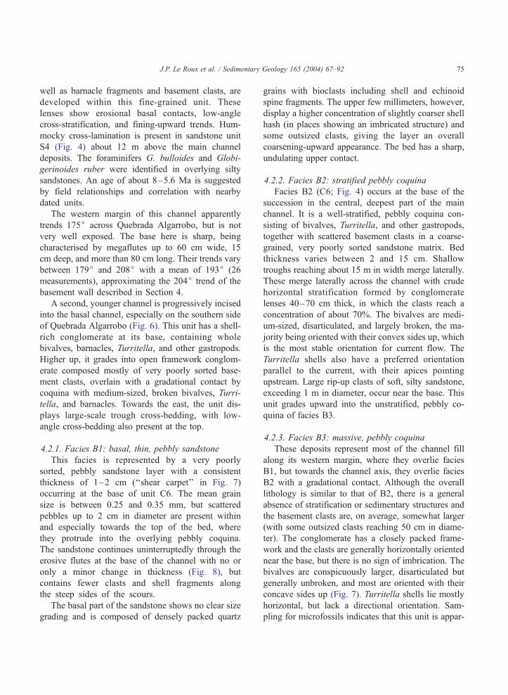
well as barnacle fragments and basement clasts, are
developed within this fine-grained unit. These
lenses show erosional basal contacts, low-angle
cross-stratification, and fining-upward trends. Hum-
mocky cross-lamination is present in sandstone unit
S4 (Fig. 4) about 12 m above the main channel
deposits. The foraminifers G. bulloides and Globi-
gerinoides ruber were identified in overlying silty
sandstones. An age of about 8–5.6 Ma is suggested
by field relationships and correlation with nearby
dated units.
The western margin of this channel apparently
trends 175j across Quebrada Algarrobo, but is not
very well exposed. The base here is sharp, being
characterised by megaflutes up to 60 cm wide, 15
cm deep, and more than 80 cm long. Their trends vary
between 179j and 208j with a mean of 193j (26
measurements), approximating the 204j trend of the
basement wall described in Section 4.
A second, younger channel is progressively incised
into the basal channel, especially on the southern side
of Quebrada Algarrobo (Fig. 6). This unit has a shell-
rich conglomerate at its base, containing whole
bivalves, barnacles, Turritella, and other gastropods.
Higher up, it grades into open framework conglom-
erate composed mostly of very poorly sorted base-
ment clasts, overlain with a gradational contact by
coquina with medium-sized, broken bivalves, Turri-
tella, and barnacles. Towards the east, the unit dis-
plays large-scale trough cross-bedding, with low-
angle cross-bedding also present at the top.
4.2.1. Facies B1: basal, thin, pebbly sandstone
This facies is represented by a very poorly
sorted, pebbly sandstone layer with a consistent
thickness of 1–2 cm (‘‘shear carpet’’ in Fig. 7)
occurring at the base of unit C6. The mean grain
size is between 0.25 and 0.35 mm, but scattered
pebbles up to 2 cm in diameter are present within
and especially towards the top of the bed, where
they protrude into the overlying pebbly coquina.
The sandstone continues uninterruptedly through the
erosive flutes at the base of the channel with no or
only a minor change in thickness (Fig. 8), but
contains fewer clasts and shell fragments along
the steep sides of the scours.
The basal part of the sandstone shows no clear size
grading and is composed of densely packed quartz
grains with bioclasts including shell and echinoid
spine fragments. The upper few millimeters, however,
display a higher concentration of slightly coarser shell
hash (in places showing an imbricated structure) and
some outsized clasts, giving the layer an overall
coarsening-upward appearance. The bed has a sharp,
undulating upper contact.
4.2.2. Facies B2: stratified pebbly coquina
Facies B2 (C6; Fig. 4) occurs at the base of the
succession in the central, deepest part of the main
channel. It is a well-stratified, pebbly coquina con-
sisting of bivalves, Turritella, and other gastropods,
together with scattered basement clasts in a coarse-
grained, very poorly sorted sandstone matrix. Bed
thickness varies between 2 and 15 cm. Shallow
troughs reaching about 15 m in width merge laterally.
These merge laterally across the channel with crude
horizontal stratification formed by conglomerate
lenses 40–70 cm thick, in which the clasts reach a
concentration of about 70%. The bivalves are medi-
um-sized, disarticulated, and largely broken, the ma-
jority being oriented with their convex sides up, which
is the most stable orientation for current flow. The
Turritella shells also have a preferred orientation
parallel to the current, with their apices pointing
upstream. Large rip-up clasts of soft, silty sandstone,
exceeding 1 m in diameter, occur near the base. This
unit grades upward into the unstratified, pebbly co-
quina of facies B3.
4.2.3. Facies B3: massive, pebbly coquina
These deposits represent most of the channel fill
along its western margin, where they overlie facies
B1, but towards the channel axis, they overlie facies
B2 with a gradational contact. Although the overall
lithology is similar to that of B2, there is a general
absence of stratification or sedimentary structures and
the basement clasts are, on average, somewhat larger
(with some outsized clasts reaching 50 cm in diame-
ter). The conglomerate has a closely packed frame-
work and the clasts are generally horizontally oriented
near the base, but there is no sign of imbrication. The
bivalves are conspicuously larger, disarticulated but
generally unbroken, and most are oriented with their
concave sides up (Fig. 7). Turritella shells lie mostly
horizontal, but lack a directional orientation. Sam-
pling for microfossils indicates that this unit is appar-

Fig. 6. Panoramic view (looking SW) of secondary channels south of Quebrada Algarrobo. Note erosional nature of younger channel (C7) and
elutriation sandstones overlying basal channel (C6). Unit C6 has a maximum thickness of about 3 m on photograph.
J.P. Le Roux et al. / Sedimentary Geology 165 (2004) 67–9276
ently sterile, compared with other stratigraphic units
where abundant foraminifers were encountered.
4.2.4. Facies B4: massive, fining-upward
biocalcarenite
Overlying facies B3 (unit C6) in the central part
of the channel with a generally sharp contact is a
buff, medium to very coarse sandstone with scat-
tered, millimeter-scale shell fragments, very similar
to the matrix of the underlying coquina. The unit is
massive, but grades upward into fine-grained, argil-
laceous sandstone. It is eroded by the overlying
pebbly coquina, so that a maximum thickness of
about 350 cm is preserved on the southwestern side
of Quebrada Algarrobo. Towards the east, this sand-
stone becomes more shell-rich, with many broken,
small fragments of barnacles. Here it is horizontally
stratified into more and less shell-rich beds 10–15
cm thick.
4.2.5. Facies B5: sedimentary breccia
A second, much smaller channel occurs a few
hundred meters south of the Chanaral de Aceituna
homestead at an elevation of about 100 m. The deep-
est part of the channel is filled by shelly conglomerate
containing many large, unoriented clasts of the sandy

Fig. 7. Shear carpet at base of debris flow deposit (thin white sandstone layer) at locality 2. Concave-upward bivalves in the debris flow
conglomerate indicate fluid escape.
J.P. Le Roux et al. / Sedimentary Geology 165 (2004) 67–92 77
and silty substrate. Just to the north of the channel
axis, a ruptured 1-m-thick bed of sandstone is appar-
ently enclosed in a massive, coarser-grained sandstone
bed. The latter becomes very thin at the base of the
block, disappearing in places, but is apparently linked
to its upper part by large cracks traversing the block
(Fig. 9).
Fig. 8. Megaflute in fallen block representing base of channel at locality 2
and the overlying debris flow (facies B3) can be clearly seen, the former be
shear carpet does not change significantly within the flute, indicating its d
4.3. Facies association C: fining-upward sandstones,
poorly sorted conglomerates, inclined sandy macro-
forms, and diatom-containing tuffs
The outcrop from locality 3 described here lies at
an elevation of 20 m above sea level on the southern
side of Quebrada Chanaral below the NW-trending
a. The textural difference between the basal shear carpet (facies B1)
ing much finer (smoother appearance on photo). The thickness of the
eposition during a subsequent, nonturbulent event.

Fig. 9. Sandstone bed traversed by cracks injected with coarser-grained sand from above, locality 2. Similar cracks apparently injected from the
base occur in the same bed. For explanation, see text and Fig. 13.
J.P. Le Roux et al. / Sedimentary Geology 165 (2004) 67–9278
scarp (Fig. 1), along the shallow trough formed by the
basement topography (Fig. 2). It shows a basal suc-
cession of sandstones and conglomerates dated at
7.3–5.2 Ma by Sr isotopes and the foraminifer B.
aenariensis (Le Roux et al., in press). These deposits
were truncated by a land- and seaward-dipping ero-
sional surface, forming a prominent ‘‘ridge’’ that was
subsequently onlapped by argillaceous, very fine-
grained sandstones as well as diatom-containing vol-
canic tuffs (Figs. 10 and 11). The onlap succession
was dated at between 4.5 and 3.4 Ma by the joint
presence of B. aenariensis and G. calida (Le Roux et
al., in press). A younger conglomerate directly over-
lies the basal succession as well as the upper onlap
units with an erosional contact. It has a probable age
of 3.4–2.6 Ma as indicated by the joint presence of
the pelecypod Chlamys hupeanus (Late Pliocene) and
the gastropods Chorus blainvillei (Late Miocene to
Late Pliocene) and Chorus giganteus (Late Pliocene
to middle Pleistocene). The basal and onlap sediments
are also overlain by shales containing the foraminifer
G. inflata, indicating a probable age of less than 2.6
Ma, in turn overlain by a coquina dated by 87Sr/86Sr at
2.0–1.8 Ma (Le Roux et al., in press).
4.3.1. Facies C1: massive, bioturbated biocalcarenite
The lowermost unit exposed below the onlap
surface is a massive, fine-grained, intensely biotur-
bated (Thalassinoides) sandstone with scattered shell
fragments, exceeding 4 m in thickness. Its uppermost
20 cm is rich in organic material, showing 1-m-wide
troughs and linguoid ripple cross-lamination as well
as small slumps. This unit is sharply overlain by
massive, bioturbated sandstone grading upward into
very poorly sorted, coarse-grained sandstone contain-
ing angular quartz, feldspar, and volcanic clasts ex-
ceeding 1 cm in diameter. The grain size varies
irregularly, but there is a generally coarsening-upward
trend up to about 90 cm from the base, from where
this second unit passes gradually into a meter-thick,
medium-grained sandstone with pockets of very poor-
ly sorted sandstone containing clasts up to 5 mm in
diameter. No sedimentary structures except bioturba-
tion are visible.
A prominent (at least 5 m deep) narrow chute cuts
through the upper sandstone into the lower sandy unit.
It has very steep edges (76j) and trends between 178jand 208j, being filled by a succession of 3- to 15-cm-
thick beds of gritty sandstone grading upwards into
fine, massive sandstone (Fig. 11). Contacts between
the units are sharp and bedding dips increase to about
48j against the chute edges.
4.3.2. Facies C2: coarse, pebbly coquina
The units described above are truncated and over-
lain by up to 1 m of medium to coarse, pebbly coquina

Fig. 10. Outcrop showing basal succession of sandy debris flow deposits overlain by conglomerate deposited by turbulent flow at locality 3
(looking E). Geological hammer (encircled) for scale. Outlined is a deep scour chute truncating the sandy debris flow deposits, which is filled by
several subsequent sandy turbidites. On the right, the erosional surface is onlapped from the southwest by argillaceous sandy turbidites. The
diatom-containing tuffs were deposited by upwelling currents.
J.P. Le Roux et al. / Sedimentary Geology 165 (2004) 67–92 79
with very poorly sorted, angular to well-rounded
cobbles and boulders of basement, intrusive rocks,
lava, phosphate, and yellowish sandstone. No imbri-
cation is observed, but the largest boulders (reaching
110 cm in diameter) tend to fill the deepest chutes.
The shelly matrix is dominated by barnacle and pecten
Fig. 11. Measured stratigraphic columns at locality 3. The lower left column
right shows details of the onlap units. Dotted lines show stratigraphic rela
fragments, and is very poorly sorted. Towards the
northeast, the basal contact of the conglomerate cuts
into the underlying units, where the unit presents
large, shallow troughs (trending 188j) lined with
scattered cobbles and filled by low-angle cross-bed-
ded coquina with clasts and boulders. The coquina
shows the succession below the erosional onlap surface. That on the
tionships. Vertical scale applies to both columns.

J.P. Le Roux et al. / Sedimentary Geology 165 (2004) 67–9280
grades upward into 35 cm of massive to horizontally
and low-angle cross-stratified, medium-grained bio-
calcarenite with fine-grained shell fragments oriented
parallel to the bedding.
4.3.3. Facies C3: inclined sandy macroforms
The erosional onlap surface strikes 293j with a dip
decreasing downward from 20j to 12jS. The onlap
succession consists of a series of 20- to 180-cm thick
sandstone beds, the thickness of each bed increasing
away from the ridge formed by the onlap surface (Fig.
10). All the sandstones have sharp bases in places
overlain directly by isolated shells, cobbles, pebbles,
or pebble lenses, but there is a scarcity of floating
larger clasts within them. The grain size of all beds
increases conspicuously towards the onlap surface
(e.g., from very fine-grained to coarse-grained over
a distance of 10–15 m). The sandstones consist of
very poorly sorted grains in a highly argillaceous
matrix that generally decreases in percentage upward,
with some exceptions where the opposite trend is
observed. A conspicuous coarse-tail normal grading
is present, however, with sorting improving notice-
ably towards the bed tops. Although most beds are
massive, some show horizontal lamination or small-
scale trough cross-lamination at the top, where bio-
turbation is also present. The burrows are filled by
coarser material from the base of the overlying unit.
On the northeastern, poorly exposed side of the
basal ridge, onlap relationships are also evident. The
southwestward-onlapping units are fine- to very fine-
grained sandstones with horizontal and ripple lamina-
tion, varying in thickness between 40 and 50 cm.
They also have sharp basal contacts.
4.3.4. Facies C4: diatom-containing tuffs
Interbedded with the sandy beds are a few white-
weathering, tuffaceous, argillaceous sandstone beds
containing diatoms, including Chaetoceros resting
spores, Stephanopyxis, Thalassiosira, and Gramma-
tophora species, as well as P. sulcata. These units
vary in thickness between and 180 and 280 cm, have
sharp basal contacts, and, in some cases, display
planar cross-lamination dipping at angles of 3–13jtowards the northeast (038j) (i.e., against the general
current flow). Horizontal and ripple lamination (also
oriented towards the northeast) and extensive biotur-
bation (Megagrapton) consisting of branched hori-
zontal tubes about 1 cm in diameter and up to 30 cm
in length are also present.
5. Facies interpretation
5.1. Facies association A: foot-of-scarp traction
current, rock fall, and debris flow deposits
Field relationships in this spectacular outcrop
clearly indicate that the poorly sorted, unstratified
conglomerates of this facies formed by sporadic
collapse of the basement wall onto the channel floor,
which consists of finer-grained shelly sandstones and
coquinas.
5.1.1. Facies A1: foot-of-scarp traction current
deposits
The fine-grained, shelly sandstones are similar to
the deposits filling modern submarine canyons. Scott
and Birdsall (1978), for example, described samples
collected at water depths between 14 and 400 m along
the Hueneme Canyon on the Californian coast. Sedi-
ments occurring along the canyon wall in this case
consist of thinly laminated, silty sands with pelecypod
and gastropod shells and few biogenic structures,
contrasting with the highly bioturbated central canyon
floor deposits.
The presence of mostly disarticulated, fragmented
shells of oysters (Ostrea sp.), pecten, barnacles, and
Turritella in facies A1 suggests that these sediments
were probably derived from shallower water and were
transported along the scarp by currents. The forami-
nifera also seem to represent a mixture of sedimentary
environments: T. gramen is a robust species found in
beach deposits (Boltovskoy, 1955), G. bulloides lives
preferentially in intermediate water depths between 50
and 100 m (Be and Tolderlund, 1971), and sinistrally
coiled N. pachyderma is essentially a deep-water
species (Be and Tolderlund, 1971; Sautter and Thu-
nell, 1991), although it may also occur in shallower
water. The first two species were therefore probably
derived from shallow coastal areas, whereas the last
may represent an actual water depth of between 50
and 500 m.
The orientation of shell fragments parallel to the
borders of basement blocks indicates sedimentation
from suspension, possibly representing material

J.P. Le Roux et al. / Sedimentary Geology 165 (2004) 67–92 81
churned up by blocks falling and sliding from the
scarp. The coquina lenses were probably deposited by
stronger currents capable of transporting coarser ma-
terial and eroding the sandy substrate.
5.1.2. Facies A2: rock fall and debris flow deposits
All six conglomerate units (C1–C6) are interpreted
as rock fall and debris flow deposits originating
directly from the basement cliff against which they
terminate. This is suggested by their poor sorting,
generally angular clasts, absence of stratification, and
the presence of outsized clasts along the upper contact
of the beds, as well as the imbrication dipping
obliquely towards the basement wall.
The thin sandstone layer continuing laterally
from unit C1 may represent material churned up
by and/or expelled from the debris flow and
deposited beyond the stalled head and margins of
the latter, thus representing surface transformation
and elutriation deposits (Hampton, 1972; Fisher,
1983).
The pebble pockets at the base of unit C2 have
been described as typical of slurried beds, interpreted
to be deposits of debris flow (Mutti et al., 1978;
Shanmugam, 2000). However, the small scale of these
lenses, as well as the tight packing of the pebbles, may
indicate an origin as debris falls rather than flows.
In unit C3, the juxtaposition of the conglomerate
and basement wall in the northern part of the outcrop
implies that sedimentation processes must have been
somewhat different from those normally assumed for
mass flows. Imbrication in both units dips obliquely
towards the basement cliff, indicating the latter as the
principal source of the angular clasts, whereas the
well-rounded cobbles could not have been shaped by
transport over a distance of only a few meters. They
must therefore have originated by falling from the
scarp edge, where they had been rounded by wave
action at the beginning of marine transgression over
the basement platform (Fig. 12). The fact that they are
intermingled with angular scarp debris indicates that
at least the upper part of the wall collapsed. Due to the
close proximity of the debris flow deposits to the wall,
this in turn implies that some of the clasts fell freely or
bounced to their present position. The middle sandy
subunit in C3 may thus represent material churned up
by these falling basement cobbles and boulders,
forming a suspension cloud settling out on top of
the debris, similar to that observed around isolated
basement cobbles and boulders in the traction current
foot-of-scarp deposits. This is supported by its fining-
upward trend.
The upper subunit of C3 overlies an irregular
contact scoured into the underlying sandy subunit,
which was apparently caused by turbulent flow. Such
flows may originate from water displaced away from
the foot of the cliff by the large volume of material
free-falling and sliding from above.
The apparently uninterrupted nature of unit C3
away from the basement wall suggests that caution
should be exercised when interpreting inverse grading
in such deposits. Obviously, some time elapsed be-
tween the deposition of the middle sandy subunit from
suspension and the second major collapse of the
canyon wall. It is therefore unlikely that the apparent-
ly merged, coarsening-upward basal and upper debris
flows represent one event at a greater distance from
the source.
The scoured and undercut basal contact of unit C3
at this locality obviously did not originate from
turbulent flow alone, as indicated by the contact-
parallel orientation of shell fragments in the silty
sandstones below the deeper chute forms. The latter
were probably formed by large blocks bouncing and
sliding ahead of the debris flows, indenting the soft
substrate and reorienting the shell fragments by their
weight. A load cast origin in this case seems unlikely
because large basement boulders lying just above the
contact are not associated with a deepening basal
contact directly below them, as would have been
expected in this case (Fig. 5). However, minor subse-
quent modification of the boulder indentation chutes
by turbulent flow is indicated by their slightly under-
cut walls, unlikely to have been caused by the
boulders. These flows may have originated from water
displaced by the falling debris and accelerating along
the indentation chutes.
The erosional basal contact of unit C4 suggests the
passage of an earlier nondepositing turbulent flow.
The inverse-to-normal grading indicates basal shear-
ing accompanied by surface flow transformation,
perhaps with the elutriation of fines by escaping fluids
(Fisher, 1983). An increase in clast size along the flow
path accompanied by the presence of some very large
boulders is also typical of debris flow fronts, where
debris fall blocks are common (Bagnold, 1968; Suwa,

Fig. 12. Wave-reworked boulders overlying basement platform, which formed during a marine transgression between 16 and 15 Ma. These are
‘‘broken rounds’’ [i.e., well-rounded clasts that have subsequently been broken by (a) very-high-energy event(s)]. Geological hammer (next to
boulder in centre of photograph) for scale. At locality 1, similar boulders were incorporated into the rock falls, mixing with the angular clasts of
the latter.
J.P. Le Roux et al. / Sedimentary Geology 165 (2004) 67–9282
1988; Sohn, 2000). These features occurring within a
relatively short distance from the debris source sug-
gest that the flow rapidly froze.
In spite of the proximity of these conglomerates
to their origin, it is interesting that they already
exhibit many of the characteristics of typical debris
flow deposits, such as protruding outsized clasts. As
it is difficult to visualise shear sorting taking effect at
a distance of only meters from the source, it is
possible that many such clasts owe their position at
the top of debris flows to the fact that they fell
directly from the collapsing wall onto the developing
flow, being unable to sieve through to the bottom as
would have been the case for smaller clasts. Such
outsized clasts may ride for long distances down
submarine canyons, perhaps in the process advancing
towards the snout of the flow by virtue of their
greater momentum.
The presence of imbrication so close to the
canyon wall also indicates that laminar shearing
already commenced at the collapse-and-slide stage,
in this case probably enhanced by the up to 28jangle of the beds against the wall. Imbrication in
debris flow deposits has been reported by various
authors (e.g., Nemec, 1990; Sohn, 2000), but it
may be that its development requires a high shear-
ing rate, as this structure was not noted in any of
the more distal debris flow deposits described in
Section 5.2.
5.2. Facies association B: detachment, shear carpet,
debris flow, elutriation, and rip-up raft deposits
The general setting of these channels is shown by
the nature of the underlying and overlying deposits.
The underlying silty sandstone with horizontal bio-
turbation obviously represents a low-energy environ-
ment, whereas the fining-upward lenses of coquina
indicate minor, waning currents transporting coarser
material and disturbing the tranquil environment from
time to time. Water depths were probably on the order
of 100–140 m, as indicated by the presence of
hummocky cross-lamination as well as the foramini-
fers G. bulloides and G. ruber, which according to
Phleger (1960) are typical of the inner continental
shelf. The presence of megaflutes at the base of the
channel indicates that it was eroded by a highly
turbulent flow, but the channel-fill facies B1–B5
apparently represent different stages of deposition.
5.2.1. Facies B1: shear carpet deposits
The fact that this sandstone layer was apparently
unaffected by the megaflute topography indicates that
its deposition postdated the formation of the flutes and

J.P. Le Roux et al. / Sedimentary Geology 165 (2004) 67–92 83
that its nature was not that of a typical turbulent flow,
which would have filled the scours more evenly as a
result of the sudden drop in current velocity in areas of
expanding flow depth.
The sandstone layer is considered to represent a
basal shear carpet. The term ‘‘traction carpet’’ has
been applied to such deposits by various authors (e.g.,
Dzulynski and Sanders, 1962; Sohn, 1997), but as
correctly pointed out by Shanmugam (2000), such
dense flow layers have a plastic rheology and laminar
flow state, so that the term ‘‘traction’’ in this case is
misleading. These deposits are commonly only a few
centimeters thick and normally develop beneath rap-
idly dissipating, turbulent sediment flows including
turbidity currents (Yagishita, 1994), pyroclastic flows
(Chough and Sohn, 1990), and subaerial hypercon-
centrated flows (Todd, 1989). Energy is provided to
basal shear carpets by the shearing action of the
overlying flow, so that grain-to-grain interactions
dominate. Although some authors have attributed
the inverse grading typical of basal shear carpets to
the dispersive pressure characterising such flows (e.g.,
Todd, 1989; Hiscott, 1994), this concept as originally
proposed by Bagnold (1954) has been challenged
recently. Sohn (1997) considered a variety of process-
es, including kinematic sieving (Middleton, 1970), a
geometrical mechanism whereby large grains climb
over smaller grains (Haff, 1991), as well as the
drifting of larger grains toward the zone of least
dispersive stress at the top of the collision zone, which
overlies a basal friction zone in basal shear carpets.
Legros (2002) argued that dispersive pressure in grain
flows or basal shear carpets cannot be invoked as a
mechanism for the upward segregation of large par-
ticles because an increase in dispersive pressure
would cause an immediate expansion of the flow until
it equals the applied normal stress again. Only par-
ticles lighter than the bulk density of the flow can
therefore be pushed upward. Le Roux (2003), how-
ever, challenged this concept, arguing that basal shear
carpets represent a stage of disequilibrium before
expansion can dissipate the dispersive pressure. He
proposed a combination of kinematic sieving in the
upper, expansional collision zone and kinematic
squeezing in the basal, compressive friction zone as
a mechanism for inverse size grading.
In the present case, the nonorganic fraction of the
basal shear carpet is not clearly size-graded, with the
exception of some outsized clasts (up to 2 cm in
diameter) floating within or occurring at the top of the
layer and protruding into the overlying debris flow.
However, the upper few millimeters do contain more
shell hash, which is slightly coarser (in length, but not
in volume) than the nonorganic grains. The absence of
large shell fragments so typical of the overlying debris
flow deposit also indicates that these were in some
manner eliminated from the basal shear carpet. To
explain this observation, the following mechanism is
envisaged: As the shear carpet developed, expansion
in the upper collision zone caused kinematic sieving
(i.e., the momentary creation of holes in the agitated
granular mass, through which the smaller particles
could fall more easily than the larger ones) (Middle-
ton, 1970; Savage and Lun, 1988). Due to the shear-
ing action, shell fragments would be oriented
horizontally, presenting their largest surface areas to
the holes and consequently being unable to penetrate
to the base of the flow. The concentration of small
grains in the developing, basal friction zone would
also lead to fluid expulsion, perhaps helping to
suspend the small shell fragments in the overlying
collision zone.
Sohn (1997) suggested that basal shear carpets
should increase progressively in thickness with con-
tinued sedimentation. If the base of the collision zone,
which is initially thicker than the friction zone (Fig. 3;
Sohn, 1997), shifts upward simultaneously with the
growth of the latter (Le Roux, 2003), this would lead
to an ungraded basal friction zone showing only a
slight change in grain size or in the percentage of shell
fragments at the top where it grades into the collision
zone. The relative thickness of the friction and colli-
sion zones may depend therefore on the duration of
the flow more than on the type of flow, with the
friction zone increasing in importance during more
sustained flows.
5.2.2. Facies B2: detachment deposits
The occurrence of traction structures and large
sandstone rafts within this facies indicates turbulent
flow capable of eroding the soft, but cohesive sandy
substrate and incorporating chunks of it into the
resulting deposits. However, the fact that these giant
rip-up clasts do not rest on the base itself suggests
hindered settling owing to a high concentration of
suspended particles.

J.P. Le Roux et al. / Sedimentary Geology 165 (2004) 67–9284
These deposits are interpreted as having formed by
detachment of debris from a hydroplaning debris flow
front, its disintegration and partial dilution by mixing
with the ambient seawater, followed by deposition
well ahead of the more slowly advancing main debris
flow. Similar processes have been described in lahars
by Pierson and Scott (1985), Smith (1986, 1987), and
Scott (1988), who referred to sediments of this origin
as hyperconcentrated flow deposits. They have char-
acteristics intermediate between debris flows and
streamflows, producing ungraded or normally graded
gravel and crudely stratified gravelly sand deposits
(Harrison and Fritz, 1982). However, the term is
currently ambiguous, having been applied to both
Newtonian fluids characterized by a turbulent state
in which coarse and fine particles settle together, or to
Bingham fluids characterized by a high sediment
concentration and laminar state, in which coarse and
fine particle are deposited together by freezing (Qian
et al., 1980). The genetic term ‘‘detachment deposits’’
is preferred here to avoid confusion.
The fact that this facies only occurs in the deepest
part of the channel and not along its margins may
reveal an important concept concerning the processes
involved. It is to be expected that a debris flow would
attain its highest velocity along the channel axis. One
of the conditions for hydroplaning is that the densio-
metric Froude number Frd be higher than 0.4 (Mohrig
et al., 1998). Frd is given by:
Frd ¼ V=M½ðqd=qf � 1Þghcosh� ð1Þ
where V is the velocity of the debris flow, qd is the
density of the debris flow, qf is the density of the
ambient fluid, g is the acceleration of gravity, h is the
debris flow thickness, and h is the slope angle. It
follows that Frd would be highest in the channel
centre, so that 0.4 may be exceeded here and not
along the slower-moving channel margins.
A second factor conditioning hydroplaning is the
time scale of pore pressure decay R (Iverson and
LaHusen, 1989; Mohrig et al., 1998; Sohn, 2000):
R ¼ d2l=kE ð2Þ
where d is a characteristic length identified with the
average flow depth, l is the viscosity of the interstitial
fluid, k is the permeability of the debris, and E is the
uniaxial compression modulus or stiffness of the
debris. R would thus be higher in the channel centre
due to the increased flow depth, enhancing the possi-
bility of hydroplaning. It is thus conceivable that the
fastest-moving central part of a channelised debris
flow may hydroplane and produce detachment depos-
its directly downslope, whereas the margins may be
nonhydroplaning and lack such underlying deposits.
5.2.3. Facies B3: cohesionless debris flow deposits
The massive, ungraded nature of this facies,
together with its poor sorting and sandy matrix, is
typical of cohesionless debris flow deposits domi-
nated by frictional grain interactions (Kim et al.,
1995; Sohn, 1997). The horizontal clast alignment
suggests laminar shear (Fisher, 1971), which is
supported by the presence of a basal shear carpet
normally associated with laminar, (pseudo)plastic
flow (Postma et al., 1988; Shanmugam, 2000). It
therefore probably behaved as a Bingham fluid. The
concave-up orientation of the bivalves indicates
fluid escape, which may be supported by the
absence of microfossils. Although foraminifera have
the density of calcite (2.71), their hollow interiors
would have diminished their settling velocity and
thus facilitated their expulsion. According to Shan-
mugam (2000), water escape is common in sub-
aqueous debris flows. In experimental studies, sandy
debris flows showed water entrapment beneath the
flow, followed by water escape to form dish struc-
tures, vertical pipes, and sand volcanoes (Mohrig et
al., 1998). Owing to the coarse nature of the debris
flow deposits described here, however, these types
of structures would be difficult to observe, if
formed at all.
5.2.4. Facies B4: elutriation deposits
The similarity between the sandstone and the
matrix of the underlying debris flow deposit suggests
that it may have been derived from the latter by
surface transformation and elutriation (Fisher, 1983).
Dilution and stripping of sand from the top of the
debris flow (Hampton, 1972) and expulsion of fines
from within the latter by escaping fluids would have
generated an upper turbulent cloud, in this case
lagging behind the faster-moving debris flow deposits.
Sohn et al. (1999) interpreted thinly stratified, coarse
to fine-grained sandstone overlying debris flow con-
glomerate as the deposits of hyperconcentrated flows

J.P. Le Roux et al. / Sedimentary Geology 165 (2004) 67–92 85
generated behind the debris flow head by surface flow
transformation. This is exhibited towards the western
channel margin in the present case. According to
Shanmugam (2000), sandy turbidites show a general
lack of cross-bedding and a characteristic normal
grading, which is displayed in the central part of the
channel. The difference in sedimentation style may be
due to larger volumes of sand having been expelled in
the central, faster-moving, and hydroplaning part of
the debris flow, leading to denser turbidity currents
and rapid dumping of the sediment load (as in the
basal unit of the Bouma cycle), whereas the channel
margin may have experienced less elutriation, forming
more dilute turbidity currents and depositing horizon-
tal beds (second unit of the Bouma cycle).
5.2.5. Facies B5: rip-up raft deposits
The fact that sandstone rafts occur throughout the
channel thickness of several meters may suggest that
they originated by undercutting and collapse of the
channel margin, but an alternative mechanism is
suggested by the cracks described above (Fig. 9).
The medium to coarse sandstone filling the cracks
appears to have been injected into the latter from both
above and below (not shown in Fig. 9), apparently
under high pressure. As the fractures are obviously
not mudcracks, a likely explanation is that they
formed during an earthquake, followed soon after by
a tsunami, causing a strong high-density backflow
accentuated along the scarp and secondary channel
axes. Experiments have shown that high-concentra-
tion beds may develop at the base of currents under-
going rapid deposition by sediment falling out from
suspension (Middleton, 1967; Vrolijk and Southard,
1997). They are driven by shear from the overriding
flow. The high dispersive pressures developing within
such pseudoplastic quick beds could cause injection
of sand into fractures, widening the latter and even
penetrating the entire bed and proceeding along its
basal contact, as seems to have been the case here.
Similar features have been reported in submarine
canyons by Morris and Busby-Spera (1988), as well
as in subaqueous volcaniclastic gravity flows (Bal-
lance and Gregory, 2001). Sand-injected cracks may
thus be a characteristic feature of high-pressure hyper-
concentrated flows and especially of tsunami events.
Fractured bed blocks can be lifted and separated from
the substrate in this manner, riding down the channels
on a cushion of high-pressure quicksand. Down-
current tilting of some fractured blocks would expose
their up-current margins to the upward-increasing,
laminar shearing action of the quick bed and also
assist in their being plucked from the substrate (Fig.
13). Camacho et al. (2002) show such a tilted margin
frozen in place (their Fig. 8A). Due to the upward
increase in the shear velocity of laminar flows, some
blocks thus separated from the substrate may be
transported down-current in a tumbling fashion, pro-
gressively climbing upward into the flow as assisted
by kinematic sieving. The high density of the quick
bed would prevent them from sinking.
5.3. Facies association C: continental slope deposits
An upper continental slope environment is indi-
cated for this facies (Figs. 10 and 11) by the
presence of sinistrally coiled N. pachyderma, which
is often encountered at depths greater than 200 m
on the upper continental slope (Lagoe, 1984) as
well as G. inflata and O. universa, foraminifers
common in hemipelagic sediments (Natland, 1976).
The presence of rare grass phytoliths may indicate
transport by turbidity currents from shallow coastal
areas.
5.3.1. Facies C1: sandy debris flows
The two units at the base of the measured section
(Fig. 11) are interpreted as sandy debris flows because
of their massive nature, floating clasts, and coarsen-
ing-upward trend in the case of the upper sandstone.
The sedimentary structures in the uppermost part of
the basal unit indicate current flow, possibly due to
surface flow transformation, whereas the small slumps
may be the result of shearing by the overlying sandy
debris flow. Pebbly pockets in the upper part of the
latter flow are also typical of slurried beds and debris
flows (Mutti et al., 1978). The presence of Thalassi-
noides in submarine canyons and deeper marine
environments is well documented (Buatois et al.,
2002).
The massive, fining-upward, chute-filling beds
were probably deposited from suspension, as sup-
ported by the fact that they drape upward against
the steep channel walls. They are interpreted as
turbidites deposited after the channel had been eroded
by a turbulent nondepositing flow.

Fig. 13. Plucking process by quicksand injection into cracks, widening the latter and separating the block from the substrate. Tilting of the block
exposes it to the laminar shearing action of the quick bed and overturns it in a down-current direction, in the process climbing into the flow.
J.P. Le Roux et al. / Sedimentary Geology 165 (2004) 67–9286
5.3.2. Facies C2: gravelly, turbulent flows
The conglomerate was apparently deposited by a
highly competent, turbulent flow, as indicated by the
large-scale traction structures. Komar (1970) pro-
posed that pebble and cobble-size material may be
transported by turbidity currents along confined
environments such as channels, which is thus sup-
ported by the present study. The fining-upward
nature of the conglomerate indicates waning flow
conditions.
5.3.3. Facies C3: inclined turbiditic macroforms
The fact that the dip direction (203j) of the
erosional onlap surface parallels the erosion chute
described above as well as the transport direction
given by megaflutes at the base of the channelised
debris flow deposits implies that it was eroded by a
nondepositing turbulent current flowing in the same
general direction.
The massive, fining-upward nature of the sand-
stones, together with their high clay content, is typical
of turbidites and indicates Newtonian rheology and
fluid turbulence (Pettijohn, 1957; Sullwold, 1960).
According to Shanmugam (2000), sands in true tur-
bidity currents are transported by suspended load and
thus show a general lack of cross-bedding and a
characteristic normal grading. The very last stages of
sand transport by the ‘‘dilute tail’’ end of turbidity
currents, however, may form thin divisions of parallel
lamination by reworking (Kuenen, 1953, 1964), as
also observed here. The fact that larger pebbles only
occur at the base of the beds suggests unhindered
settling, thus distinguishing these sandstones from
sandy debris flows. An unusual feature of these
turbidites is the fact that the clay matrix generally
decreases upward, which may be due to high sediment
concentrations dampening turbulence in the basal
parts of the flows and leading to rapid deposition,
while increased turbulence in the more diluted, upper
parts of the flows kept the finest grains in suspension.
Stanley et al. (1978) referred to similar beds as coarse,
truncated turbidites, which may form the largest
proportion of channelised sequences in the distal
sectors of submarine canyons. Middleton (1967) also
observed that high-concentration turbulent flows can
develop coarse-tail grading as a function of pseudo-
plastic behaviour.
The onlapping bedform architecture is similar to
structures recently described in a submarine canyon in
Spain by Pickering et al. (2001). This new type of
bedform was named ‘‘inclined backstepping macro-
forms’’ by these authors and also occur in the up-
stream depression immediately behind a wave-like
ridge on the surface of cohesive debris flow deposits.
The coarse-grained sandy turbidites composing the
macroforms similarly have significantly coarser up-
stream tails and show partial bioturbation towards the
bed tops. These macroforms are sigmoidal and in-
clined upstream, however, in contrast with the down-
stream-dipping macroforms described here. Pickering

J.P. Le Roux et al. / Sedimentary Geology 165 (2004) 67–92 87
et al. (2001) attribute the origin of these structures to
the deposition of high-velocity gravity flow conglom-
erates overlying erosion surfaces left by nondeposit-
ing turbidity currents. The conglomerates had a wave-
like upper surface, which acted as a seeding structure
for the accumulation of sand from successive turbidity
currents behind the crests. Lower shear velocities over
the depressions behind the crests caused the preferen-
tial deposition of sand behind these obstacles, with
flow stripping leaving pockets of coarser-grained
sediments on the upstream side of the macroforms.
The absence of modification features to the macro-
forms was taken to indicate rapid deposition and
backfilling.
A similar origin is proposed for the inclined macro-
forms described here, with the difference that the
inclined depositional surface at the base of the macro-
forms formed by nondepositing turbulent flows erod-
ing the underlying conglomerate. Subsequent sandy
turbidites were deposited not only on the downstream
side of these obstacles, however, but also on the
upstream side. The depressions on both sides were
filled in by high-density turbidity flows rapidly dump-
ing their loads due to the increase in water depth and
decrease in flow velocity, with successive turbidites
onlapping onto the crest from both sides. The ridge
was initially left bare due to an increase in flow
velocity (decrease in water depth) over its top, but
as the depressions filled up, their effect became less
until the crest itself was buried by successive flows.
Although Pickering et al. (2001) attributed the down-
stream-fining trends of their beds to flow stripping, a
more likely explanation may be simply that the
coarsest sediment load was dumped in the zone of
flow expansion immediately behind the ridge crests,
with successively finer grains settling out as flow
deceleration proceeded down the inclined surface.
The inclined macroforms would thus have grown in
a down-current direction away from the ridge crests
and not up-current from the depression onto the ridge
crest, although successive turbidites do show a back-
stepping architecture onto the latter.
5.3.4. Facies C4: upwelling deposits
The diatom assemblage of these beds is charac-
teristic of highly productive deep-water upwelling
over the continental slope (Le Roux et al., in press).
This is supported by the up-channel directed planar
cross-lamination, although the latter may also be
related to flood tidal currents rising along the sub-
marine canyon.
The upwelling deposits and the bioturbated bed
tops of the turbidites suggest that infilling of the
depression behind the ridge crest was sporadic, with
relatively long periods between successive turbidite
flows.
6. Facies relationships and sedimentological
history
The study area is characterized by numerous
lateral facies changes and units pinching out over
short distances. This is exemplified, for example, at
locality 1, where debris flow conglomerates pinch
out within 100 m from the basement cliff against
which they originated or grade into sandstone in the
direction of transport. Within secondary erosion
channels, there are also rapid facies changes per-
pendicular to the direction of transport, where
detachment deposits showing traction structures
within the channel centres grade into massive debris
flow deposits towards the channel margins. Flow
transformation processes in the down-channel direc-
tion also caused different vertical facies representing
the same event, for example, where basal shear
carpets underlie debris flow deposits or where
elutriation deposits overlie detachment deposits. In
addition, obstacles along the main canyon floor
were responsible for local facies variation by alter-
ing the hydrodynamics of turbidity currents, caus-
ing, for example, backstepping macroforms in their
wake.
Because of these abrupt facies changes and incom-
plete exposures along Quebrada Chanaral, com-
pounded by the irregular basement topography, it is
very difficult to correlate the different stratigraphic
units. At locality 1, for example, units were deposited
simultaneously on the basement platform and the
scarp floor, although the two environments were
separated vertically by at least 35 m. Here, rounded
basement boulders formed along the edge of the scarp
during marine transgression in the early Langhian (Le
Roux et al., in press) were subsequently incorporated
in Tortonian or even younger deposits at the foot of
the scarp when the wall collapsed, as indicated by the
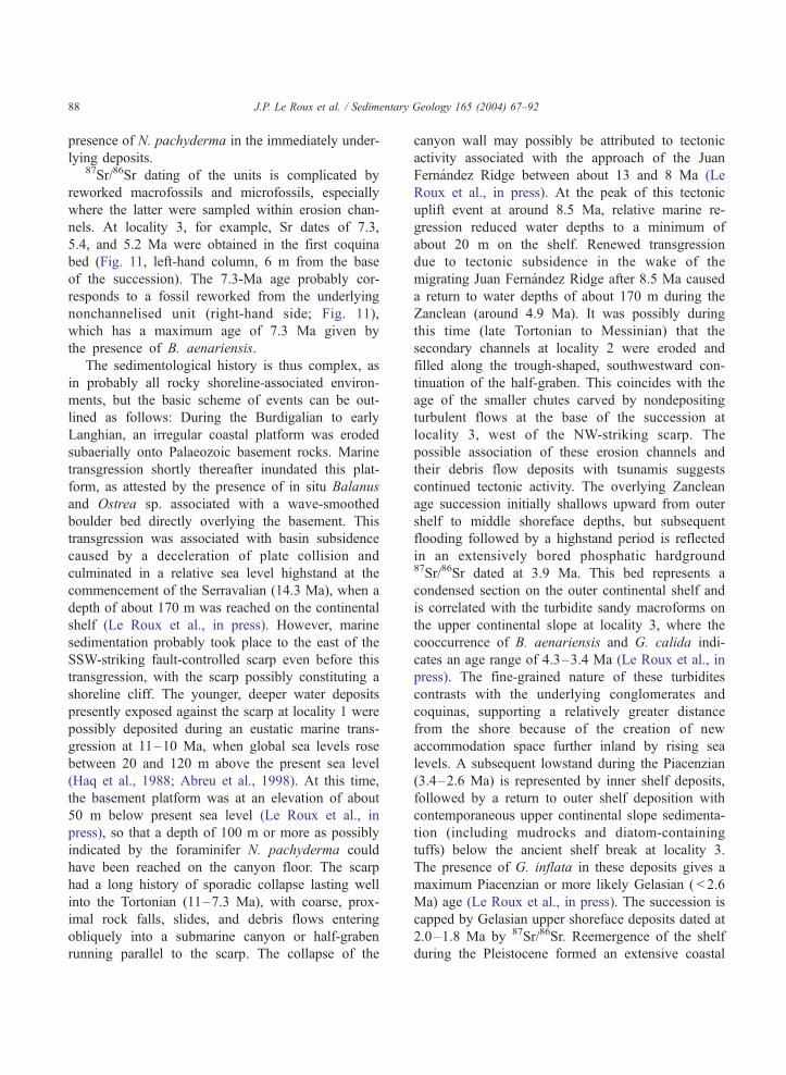
J.P. Le Roux et al. / Sedimentary Geology 165 (2004) 67–9288
presence of N. pachyderma in the immediately under-
lying deposits.87Sr/86Sr dating of the units is complicated by
reworked macrofossils and microfossils, especially
where the latter were sampled within erosion chan-
nels. At locality 3, for example, Sr dates of 7.3,
5.4, and 5.2 Ma were obtained in the first coquina
bed (Fig. 11, left-hand column, 6 m from the base
of the succession). The 7.3-Ma age probably cor-
responds to a fossil reworked from the underlying
nonchannelised unit (right-hand side; Fig. 11),
which has a maximum age of 7.3 Ma given by
the presence of B. aenariensis.
The sedimentological history is thus complex, as
in probably all rocky shoreline-associated environ-
ments, but the basic scheme of events can be out-
lined as follows: During the Burdigalian to early
Langhian, an irregular coastal platform was eroded
subaerially onto Palaeozoic basement rocks. Marine
transgression shortly thereafter inundated this plat-
form, as attested by the presence of in situ Balanus
and Ostrea sp. associated with a wave-smoothed
boulder bed directly overlying the basement. This
transgression was associated with basin subsidence
caused by a deceleration of plate collision and
culminated in a relative sea level highstand at the
commencement of the Serravalian (14.3 Ma), when a
depth of about 170 m was reached on the continental
shelf (Le Roux et al., in press). However, marine
sedimentation probably took place to the east of the
SSW-striking fault-controlled scarp even before this
transgression, with the scarp possibly constituting a
shoreline cliff. The younger, deeper water deposits
presently exposed against the scarp at locality 1 were
possibly deposited during an eustatic marine trans-
gression at 11–10 Ma, when global sea levels rose
between 20 and 120 m above the present sea level
(Haq et al., 1988; Abreu et al., 1998). At this time,
the basement platform was at an elevation of about
50 m below present sea level (Le Roux et al., in
press), so that a depth of 100 m or more as possibly
indicated by the foraminifer N. pachyderma could
have been reached on the canyon floor. The scarp
had a long history of sporadic collapse lasting well
into the Tortonian (11–7.3 Ma), with coarse, prox-
imal rock falls, slides, and debris flows entering
obliquely into a submarine canyon or half-graben
running parallel to the scarp. The collapse of the
canyon wall may possibly be attributed to tectonic
activity associated with the approach of the Juan
Fernandez Ridge between about 13 and 8 Ma (Le
Roux et al., in press). At the peak of this tectonic
uplift event at around 8.5 Ma, relative marine re-
gression reduced water depths to a minimum of
about 20 m on the shelf. Renewed transgression
due to tectonic subsidence in the wake of the
migrating Juan Fernandez Ridge after 8.5 Ma caused
a return to water depths of about 170 m during the
Zanclean (around 4.9 Ma). It was possibly during
this time (late Tortonian to Messinian) that the
secondary channels at locality 2 were eroded and
filled along the trough-shaped, southwestward con-
tinuation of the half-graben. This coincides with the
age of the smaller chutes carved by nondepositing
turbulent flows at the base of the succession at
locality 3, west of the NW-striking scarp. The
possible association of these erosion channels and
their debris flow deposits with tsunamis suggests
continued tectonic activity. The overlying Zanclean
age succession initially shallows upward from outer
shelf to middle shoreface depths, but subsequent
flooding followed by a highstand period is reflected
in an extensively bored phosphatic hardground87Sr/86Sr dated at 3.9 Ma. This bed represents a
condensed section on the outer continental shelf and
is correlated with the turbidite sandy macroforms on
the upper continental slope at locality 3, where the
cooccurrence of B. aenariensis and G. calida indi-
cates an age range of 4.3–3.4 Ma (Le Roux et al., in
press). The fine-grained nature of these turbidites
contrasts with the underlying conglomerates and
coquinas, supporting a relatively greater distance
from the shore because of the creation of new
accommodation space further inland by rising sea
levels. A subsequent lowstand during the Piacenzian
(3.4–2.6 Ma) is represented by inner shelf deposits,
followed by a return to outer shelf deposition with
contemporaneous upper continental slope sedimenta-
tion (including mudrocks and diatom-containing
tuffs) below the ancient shelf break at locality 3.
The presence of G. inflata in these deposits gives a
maximum Piacenzian or more likely Gelasian ( < 2.6
Ma) age (Le Roux et al., in press). The succession is
capped by Gelasian upper shoreface deposits dated at
2.0–1.8 Ma by 87Sr/86Sr. Reemergence of the shelf
during the Pleistocene formed an extensive coastal

J.P. Le Roux et al. / Sedimentary Geology 165 (2004) 67–92 89
plain covered by fluvio-estuarine, shelly gravel, Sr
dated at 1.0 Ma.
7. Discussion and conclusions
Many of the features described in this paper are
similar to the deposits of rocky shorelines and
associated submarine canyons. In the present case,
a fault-controlled basement scarp apparently
deflected and concentrated seaward-directed debris
flows and turbidity currents, with the development
of secondary channels parallel to the scarp. Al-
though sedimentologically active submarine canyons
have been studied fairly extensively, for example,
off California (Shepard and Dill, 1966; Shepard and
Marshall, 1973; Scott and Birdsall, 1978) and the
northeastern United States (Keller and Shepard,
1978; Drake et al., 1978), they are rarely well
exposed in the rock record (Stanley et al., 1978).
The same can be said of rocky shorelines, which
have not been well studied even in modern exam-
ples because of the difficult and often dangerous
field conditions. The exposures described here rep-
resent a wide variety of shoreline, scarp-, and
canyon-related deposits and sedimentary features
that give further insights into depositional processes
not readily revealed by dives or observations from
submersibles, coring programs, and seismic surveys.
This confirms the observation by Kelling and Stan-
ley (1978) that in some environments, ‘‘the ancient
record still appears to be providing a key to the
present.’’
The existence of turbulent, extremely erosive cur-
rents roaring down submarine channels without leav-
ing any deposits has been postulated by various
authors (e.g., Mutti and Normark, 1987), which is
supported by the presence of wide, large-scale chan-
nels or narrow, deep chutes with deposits representing
subsequent events, such as at localities 2 and 3.
Although the existence of clear water currents has
been postulated by Bouma and Hollister (1973), it
seems more likely that highly turbulent, sediment-
loaded currents carved the erosion surfaces but simply
traveled too fast to dump their load. It is also likely
that these currents are related to tsunami events, which
are fairly common along the Chilean coast and may
have been amplified by the scarp and canyon topog-
raphy. It is to be expected that such tsunamis eroded
the coastline and would have been capable of trans-
porting a fairly coarse sediment load down to the foot
of the continental slope, where a permeable deep sea
fan probably exists.
Local currents may precede debris flows due to the
displacement of water away from the base of scarps or
canyon walls suffering catastrophic collapse, leading
to basal erosion surfaces as recorded at locality 1. The
irregular basal surfaces of some debris flows may also
be related to large fall blocks bouncing, rolling, and
sliding ahead of the flows and indenting the soft
bottom sediments. These indentation chutes may be
subsequently enhanced by local turbulent flows pro-
ceeding ahead of the debris flow by water displace-
ment. Large blocks may also fall onto developing
debris flows and ride down canyons, so that protrud-
ing outsized clasts do not necessarily imply shear
sorting.
Flow transformation by hydroplaning, detach-
ment, and elutriation may be restricted to certain
parts of debris flows, in particular the deepest parts
of channels where the highest velocities are attained
and where the time scale of pore pressure decay is
also the largest. Turbulent flow developing by de-
tachment and dilution of the debris flow front may
proceed ahead of the latter and deposit somewhat
finer material showing sedimentary structures such as
horizontal and trough cross-stratification. In shelly
debris flow deposits, fluid escape structures such as
pillars and dishes may not be visible, but bivalve
shells may be oriented concave-side up. Shear car-
pets apparently also occur at the base of debris
flows, where they show floating clasts and a larger
concentration of small shell fragments in their upper
part (collision zone). This can be attributed to their
orientation (by shearing) parallel to the base and
consequent inability to infiltrate the basal friction
zone.
Sand injected from high-density, pseudoplastic
quick beds into fractures penetrating underlying strata
probably indicates earthquakes followed by tsunamis
and may thus be a characteristic feature of such
events. Plucking of large rafts from the substrate in
this manner may tilt them down-current, exposing
them to the laminar shearing action of the flow. They
may thus proceed down-current in a tumbling fashion
and climb upward into the flow at the same time,

J.P. Le Roux et al. / Sedimentary Geology 165 (2004) 67–9290
assisted by kinematic sieving, dispersive pressure, and
upward-escaping fluids.
Inclined sandy macroforms, such as recently de-
scribed for the first time in Spain, are not necessarily
sigmoidal in shape and can also dip downstream
instead of upstream on the lee sides of obstacles on
the canyon floor. Their fining-downstream trends may
be attributed to flow expansion behind canyon floor
obstacles and do not necessarily imply flow stripping.
They are thus envisaged to have grown in a down-
stream direction, with successive beds backstepping
onto the ridge crests. On the upstream side of
obstacles, similar onlapping beds may be deposited.
Acknowledgements
We are greatly indebted to K.A.W. Crook, Y.K.
Sohn, and F. Ricci-Luchi for their very helpful
comments and suggestions. Petrysia Le Roux and
Carlos Vinegas are thanked for assisting with field-
work. We also appreciate the help of Daniel
Frassinetti and Margarita Marchant in identifying the
macrofossils and foraminifera, respectively. The
research was funded by Project Fondecyt 1010691.
References
Abreu, V.S., Hardenbol, J., Haddad, G.A., Baum, G.R., Droxler,
A.W., Vail, P.R., 1998. Oxygen isotope synthesis: a Cretaceous
ice-house? In: Graciansky, P.-C., Hardenbol, J., Jacquin, T., Vail,
P.R. (Eds.), Mesozoic and Cenozoic Sequence Stratigraphy of
European Basins. SEPM Special Publication 60, SEPM Special
Publication, Tulsa, OK, pp. 75–80.
Bagnold, R.A., 1954. Experiments on gravity-free dispersion of
large solid spheres in a Newtonian fluid under shear. Proceed-
ings of the Royal Society A225, London, pp. 49–63.
Bagnold, R.A., 1968. Deposition in the process of hydraulic trans-
port. Sedimentology 10, 45–56.
Ballance, P.F., Gregory, M.R., 2001. Parnell Grits– large subaqu-
eous volcaniclastic gravity flows with multiple particle-sup-
port mechanisms. In: Fisher, R.V., Smith, G.A. (Eds.),
Sedimentation in Volcanic Settings. SEPM Special Publica-
tion 45, Tulsa, OK, pp. 189–200.
Be, A.W., Tolderlund, D.S., 1971. Distribution and ecology of liv-
ing planktonic foraminifera in surface waters of the Atlantic and
Indian Oceans. In: Funnell, B.M., Riedel, W.R. (Eds.), The
Micropaleontology of the Oceans. Cambridge Univ. Press, Cam-
bridge, pp. 105–149.
Boltovskoy, E., 1955. Recent foraminifera from shore sands at
Quequen, Province of Buenos Aires, and changes in the
foraminiferal fauna to the north and south. Contributions
to the Cushman Foundation for Foraminiferal Research 6,
39–42.
Bouma, A.H., Hollister, C.D., 1973. Deep ocean basin sedimenta-
tion. In: Middleton, G.V., Bouma, A.H. (Eds.), Turbidites and
Deep-Water Sedimentation. Proceedings of the Society for Eco-
nomic Paleontologists and Mineralogists, Pacific Section, Short
Course Lecture Notes Anaheim, pp. 79–118.
Buatois, L., Mangano, G., Acenolaza, F., 2002. Trazas Fosiles:
Senales de Comportamiento en el Registro Estratigrafico. Mu-
seo Paleontologico Egidio Feruglio, Chubut, Argentina. 381 pp.
Bundesanstalt fur Geowissenschaften und Rohstoffe, 2001. Sub-
duction processes off Chile. Cruise Report SO-161, Legs 2
and 3. SPOC, Hannover.
Camacho, H., Busby, C.J., Kneller, B., 2002. A new depositional
model for the classical turbidite locality at San Clemente State
Beach, California. American Association of Petroleum Geolo-
gists Bulletin 86, 1543–1560.
Chough, S.K., Sohn, Y.K., 1990. Depositional mechanics and se-
quences of base surges, Songaksan tuff ring, Cheju Island, Ko-
rea. Sedimentology 37, 1115–1135.
Drake, D.E., Hatcher, P.G., Keller, G.H., 1978. Suspended particle
matter and mud deposition in upper Hudson submarine canyon.
In: Stanley, D.J., Kelling, G. (Eds.), Sedimentation in Submar-
ine Canyons, Fans and Trenches. Dowden Hutchinson and Ross,
Stroudsburg, PA, pp. 33–41.
Dzulynski, S., Sanders, J.E., 1962. Current marks on firm mud
bottoms. Connecticut Academy of Arts and Science Transac-
tions 42, 57–96.
Felton, E.A., 2002. Sedimentology of rocky shorelines: 1. A review
of the problem, with analytical methods, and insights gained
from the Hulopoe Gravel and the modern rocky shoreline of
Lanai, Hawaii. Sedimentary Geology 152, 221–245.
Fisher, R.V., 1971. Features of coarse-grained, high-concentration
fluids and their deposits. Journal of Sedimentary Petrology 41,
916–927.
Fisher, R.V., 1983. Flow transformation in sediment gravity flows.
Geology 11, 273–274.
Haff, P.K., 1991. Basic physical models in sediment transport. In:
Kraus, N.C., Gingerich, K.J., Kriebel, D.L. (Eds.), Coastal Sedi-
ments ’91: Proceedings of a Specialty Conference onQuantitative
Approaches to Coastal Sediment Processes, vol. 1. American
Society of Civil Engineers, Reston, VA, pp. 1–14.
Hampton, M.A., 1972. The role of subaqueous debris flows in
generating turbidity currents. Journal of Sedimentary Petrology
42, 775–793.
Haq, B.U., Hardenbol, J., Vail, P.R., 1988. Mesozoic and Cen-
ozoic chronostratigraphy and cycles of sea level change. In:
Wilgus, C.K., Hastings, B.S., Kendall, C.G.St.C., Posament-
ier, H.W., Ross, C.A., Van Wagoner, J.C. (Eds.), Sea Level
Changes: An Integrated Approach. SEPM Special Publication
42, Tulsa, OK, pp. 71–108.
Harrison, S., Fritz, W.J., 1982. Depositional features of March 1982
Mount St. Helens sediment flows. Nature 299, 720–722.
Hiscott, R.N., 1994. Traction-carpet stratification in turbidites—fact
or fiction? Journal of Sedimentary Petrology A64, 204–208.

J.P. Le Roux et al. / Sedimentary Geology 165 (2004) 67–92 91
Iverson, R.M., LaHusen, R.G., 1989. Dynamic pore-pressure fluc-
tuations in rapidly shearing granular materials. Science 346,
796–799.
Keller, G.H., Shepard, F.P., 1978. In: Stanley, D.J., Kelling, G.
(Eds.), Sedimentation in Submarine Canyons, Fans and
Trenches. Dowden Hutchinson and Ross, Stroudsburg, PA,
pp. 15–32.
Kelling, G., Stanley, D.J., 1978. In: Stanley, D.J., Kelling, G.
(Eds.), Sedimentation in Submarine Canyons, Fans and
Trenches. Dowden Hutchinson and Ross, Stroudsburg, PA,
pp. 377–388.
Kim, S.B., Chough, S.K., Chun, S.S., 1995. Bouldery deposits in
the lowermost part of the Cretaceous Kyokpori Formation, SW
Korea: cohesionless debris flows and debris falls on a steep-
gradient delta slope. Sedimentary Geology 98, 97–119.
Komar, P.D., 1970. The competence of turbidity current flow. Geo-
logical Society of America Bulletin 81, 1555–1562.
Kuenen, Ph.H., 1953. Significant features of graded bedding.
American Association of Petroleum Geologists Bulletin 37,
1044–1066.
Kuenen, Ph.H., 1964. Deep-sea sands and ancient turbidites. In:
Bouma, A.H., Brouwer, A. (Eds.), Turbidites: Developments
in Sedimentology, vol. 3. Elsevier, Amsterdam, pp. 3–33.
Lagoe, M.B., 1984. Recent foraminiferal biofacies in the Arctic
Ocean. In: Oertli, H.J. (Ed.), Benthos ’83. Proceedings of the
2nd International Symposium on Benthic Foraminifera, Pau et
Bordeaux, 353.
Legros, F., 2002. Can dispersive pressure cause inverse grading in
grain flows? Journal of Sedimentary Research 72, 166–170.
Le Roux, J.P., 1994. Persistence of topographic features as a result
of non-tectonic processes. Sedimentary Geology 89, 33–42.
Le Roux, J.P., 2003. Can dispersive pressure cause inverse grading
in grain flows? (Discussion). Journal of Sedimentary Research
73, 331–332.
Le Roux, J.P., Gomez, C., Venegas, C., Fenner, J., Middleton, H.,
Marchant, M., Buchbinder, B., Frassinetti, D., Marquardt, C.,
Gregory-Wodzicki, K.M., Lavenu, A., 2004. Neogene–Quater-
nary coastal and offshore sedimentation in north-central Chile:
record of sea level changes and implications for Andean tecton-
ism. Journal of South American Earth Sciences (in press).
Middleton, G.V., 1967. Experiments on density and turbidity cur-
rents: III. Deposition of sediment. Canadian Journal of Earth
Science 3, 523–546.
Middleton, G.V., 1970. Experimental studies related to problems of
flysch sedimentation. In: Lajoie, J. (Ed.), Flysch Sedimentology
in North America. Special Paper 7, Geological Association of
Canada, pp. 253–272.
Mohrig, D., Whipple, K.X., Hondzo, M., Ellis, C., Parker, G., 1998.
Hydroplaning of subaqueous debris flows. Geological Society
of America Bulletin 110, 387–394.
Morris, W.R., Busby-Spera, C.J., 1988. Sedimentologic evolution
of a submarine canyon in a forearc basin, upper Cretaceous
Rosario Formation, San Carlos, Mexico. American Association
of Petroleum Geologists Bulletin 72, 717–737.
Mutti, E., Normark, W.R., 1987. Comparing examples of modern
and ancient turbidite systems: problems and concepts. In: Leg-
gett, J.R., Zuffa, G.G. (Eds.), Marine Clastic Sedimentology:
Concepts and Case Studies. G. Graham and Trotman, London,
pp. 1–37.
Mutti, E., Nilsen, T.H., Ricci Lucchi, F., 1978. Outer fan deposi-
tional lobes of the laga formation (Upper Miocene and Lower
Pliocene), east-central Italy. In: Stanley, D.J., Kelling, G. (Eds.),
Sedimentation in Submarine Canyons, Fans and Trenches.
Dowden, Hutchinson and Ross, Stroudsburg, PA, pp. 210–223.
Natland, M.L., 1976. Presidential address: paleoecology and tur-
bidites. In: Curtis, D.M. (Ed.), Depositional Environments
and Paleoecology: Foraminiferal Paleoecology. Reprint Series
2, Tulsa, OK, pp. 946–951.
Nemec, W., 1990. Aspects of sediment movement on steep delta
slopes. In: Colella, A., Prior, D.B. (Eds.), Coarse-Grained Del-
tas. Special Publication of the International Association of Sed-
imentologists 10, Tulsa, OK, pp. 29–73.
Pardo, M., Comte, D., Monfret, T., 2002. Seismotectonic and stress
distribution in the central Chile subduction zone. Journal of
South American Earth Sciences 15, 11–22.
Pettijohn, F.J., 1957. Sedimentary Rocks, 2nd ed. Harper, New
York. 718 pp.
Phleger, F.B., 1960. Ecology and Distribution of Recent Foramin-
ifera. John Hopkins Press, Baltimore. 297 pp.
Pickering, K.T., Hodgson, D.M., Platzman, E., Clark, J.D., Ste-
phens, C., 2001. A new type of bedform produced by back-
filling processes in a submarine channel, late Miocene,
Tabernas-Sorbas basin, SE Spain. Journal of Sedimentary Re-
search 71, 692–704.
Pierson, T.C., Scott, K.M., 1985. Downstream dilution of a lahar:
transition from debris flow to hyperconcentrated stream flow.
Water Resources Research 21, 1511–1524.
Postma, G., Nemec, W., Kleinspehn, K.L., 1988. Large floating
clasts in turbidites: a mechanism for their emplacement. Sedi-
mentary Geology 58, 47–61.
Qian, Y., Yang, W., Zhao, W., Cheng, X., Zhang, L., Lu, W., 1980.
Basic characteristics of flow with hyperconcentrations of sedi-
ment. Proceedings of the International Symposium on River
Sedimentation. Chinese Society of Hydraulic Engineering, Bei-
jing, pp. 175–184.
Sautter, L.R., Thunell, R., 1991. Seasonal variability in the d18Oand d13C of planktonic foraminifera from an upwelling environ-
ment: sediment trap result from San Pedro Basin, southern Cal-
ifornia bight. Paleoceanography 6, 307–334.
Savage, S.B., Lun, C.K.K., 1988. Particle size segregation in in-
clined chute flow of dry cohesionless granular solids. Journal of
Fluid Mechanics 189, 311–335.
Scott, K.M., 1988. Origins, behavior, and sedimentology of la-
hars and lahar-runout flows in the Toutle–Cowlitz River Sys-
tem. U.S. Geological Survey Professional Paper 1447-A,
A1–A74.
Scott, R.M., Birdsall, B.C., 1978. Physical and biogenic character-
istics of sediments from Hueneme submarine canyon, California
coast. In: Stanley, D.J., Kelling, G. (Eds.), Sedimentation in
Submarine Canyons, Fans and Trenches. Dowden, Hutchinson
and Ross, Stroudsburg, PA, pp. 51–64.
Shanmugam, G., 2000. 50 Years of the turbidite paradigm (1950’s–
1990’s): deep-water processes and facies models—a critical per-
spective. Marine and Petroleum Geology 17, 285–342.

J.P. Le Roux et al. / Sedimentary Geology 165 (2004) 67–9292
Shepard, F.P., Dill, R.F., 1966. Submarine Canyons and Other Sea
Valleys. Rand McNally, Chicago, 381 pp.
Shepard, F.P., Marshall, N.F., 1973. Currents along floors of sub-
marine canyons. American Association of Petroleum Geologists
Bulletin 57, 244–264.
Smith, G.A., 1986. Coarse-grained nonmarine volcaniclastic sedi-
ment: terminology and depositional process. Geological Society
of America Bulletin 97, 1–10.
Smith, G.A., 1987. The influence of explosive volcanism on
fluvial sedimentation: the Deschutes Formation (Neogene)
in central Oregon. Journal of Sedimentary Petrology 57,
613–629.
Sohn, Y.K., 1997. On traction-carpet sedimentation. Journal of
Sedimentary Research 67, 502–509.
Sohn, Y.K., 2000. Depositional processes of submarine debris flows
in the Miocene fan deltas, Pohang Basin, SE Korea with special
reference to flow transformation. Journal of Sedimentary Re-
search 70, 491–503.
Sohn, Y.K., Rhee, C.W., Kim, B.C., 1999. Debris flow and hyper-
concentrated flood-flow deposits in an alluvial fan, northwestern
part of the Cretaceous Yongdong Basin, Central Korea. Journal
of Geology 107, 111–132.
Stanley, D.J., Palmer, H.D., Dill, R.F., 1978. Coarse sediment trans-
port by mass flow and turbidity current processes and down-
slope transformations in Annot sandstone canyon– fan valley
systems. In: Stanley, D.J., Kelling, G. (Eds.), Sedimentation in
Submarine Canyons, Fans and Trenches. Dowden, Hutchinson
and Ross, Stroudsburg, PA, pp. 85–115.
Stenzel, H.B., 1944. Sections of Weches Formation: AAPG-SEPM
field trip guidebook. Houston Geological, 44–49.
Sullwold, H.H., 1960. Tarzana Fan, deep submarine fan of Late
Miocene age, Los Angeles County, California. American Asso-
ciation of Petroleum Geologists Bulletin 44, 433–457.
Suwa, H., 1988. Focusing mechanism of large boulders to a debris-
flow front. Transactions of the Japanese Geomorphological
Union 9, 151–178.
Todd, S.P., 1989. Stream-driven, high-density gravelly traction car-
pets: possible deposits in the Trabeg Conglomerate Formation,
SW Ireland and some theoretical considerations of their origin.
Sedimentology 36, 513–530.
Vrolijk, P.J., Southard, J.B., 1997. Experiments on rapid deposi-
tion of sand from high-velocity flows. Geoscience Canada 24,
45–54.
Yagishita, K., 1994. Antidunes and traction-carpet deposits in deep-
water channel sandstones, Cretaceous, British Columbia, Cana-
da. Journal of Sedimentary Petrology A64, 34–41.