Section – 2.1 11 KV RING MAIN UNITS AND ACCESSORIES
35
1 Section – 2.1 11 KV RING MAIN UNITS AND ACCESSORIES 11 KV RMU (RING MAIN UNITS) 1. Scope: - Design, engineering, manufacture, assembly, stage testing, inspection and testing before supply and delivery at site, storing, erection, installation, testing, commissioning and handing over of SCADA compatible, motorized, both side extensible/ outdoor type Ring Main Units (RMUs) with various combinations of SF6 insulated/arc quenching Load Break Switches and Vacuum Circuit breakers suitable for 11KV/433V Distribution Transformers as listed below with cable termination kits, terminal protectors, current transformers, protection relays, and with metering facility for breakers, complete with all materials and accessories, spares etc.. ( except plinth, excavation, earthing ) i. 11kV Ring Main units with 2nos. load break switches and 1 No. circuit breaker. – 18 Nos ii. 11kV Ring Main units with 4 nos. load break switches . – 3 Nos The bidder shall separately quote for the (a) Supply of each items of RMUs , (b) installation, Testing and Commissioning seperately. 2. Standards : The equipment shall conform in all respects with the requirements of the latest editions of the IEC standards stated below except where specified otherwise. Indian Title International and Standard Internationally recognized Standard IS 13118 High Voltage Alternating Current Circuit Breaker IEC 60056, 62271-100 :1991 IS High Voltage Switches IEC 60265, BS 5463 9920:1981, 1982
-
Upload
khangminh22 -
Category
Documents
-
view
2 -
download
0
Transcript of Section – 2.1 11 KV RING MAIN UNITS AND ACCESSORIES
1
Section – 2.1
11 KV RING MAIN UNITS AND ACCESSORIES
11 KV RMU (RING MAIN UNITS)
1. Scope: - Design, engineering, manufacture, assembly, stage testing, inspection and
testing before supply and delivery at site, storing, erection, installation, testing,
commissioning and handing over of SCADA compatible, motorized, both side
extensible/ outdoor type Ring Main Units (RMUs) with various combinations of SF6
insulated/arc quenching Load Break Switches and Vacuum Circuit breakers suitable
for 11KV/433V Distribution Transformers as listed below with cable termination kits,
terminal protectors, current transformers, protection relays, and with metering
facility for breakers, complete with all materials and accessories, spares etc.. (
except plinth, excavation, earthing )
i. 11kV Ring Main units with 2nos. load break switches and 1 No. circuit
breaker. – 18 Nos
ii. 11kV Ring Main units with 4 nos. load break switches . – 3 Nos
The bidder shall separately quote for the (a) Supply of each items of RMUs , (b) installation, Testing and Commissioning seperately.
2. Standards :
The equipment shall conform in all respects with the requirements of the
latest editions of the IEC standards stated below except where specified
otherwise.
Indian Title International and Standard Internationally
recognized Standard
IS 13118 High Voltage Alternating Current Circuit Breaker IEC 60056, 62271-100
:1991
IS High Voltage Switches IEC 60265, BS 5463 9920:1981,
1982
2
IS 2099 Dimensions of Indoor and Outdoor post insulators with IEC 60273
voltages > 1000 volts
IS 9921 Alternative current disconnectors and earthing switches IEC 60129, 62271-102
IS 12729: General requirements for switchgear and control gear for IEC 60298
1988 voltages exceeding 1000V.
IS 13947 Degrees of protection provided by enclosures for low IEC 60529
Part-1 voltage switchgear and control gear.
IS 2705 Current Transformers IEC-60185, 60044-1
:1992
IS: 3156 Voltage Transformers IEC 60044-2
IS: 3231 Electric Relays for power system IEC 60255
IS:1248 Meters and Instruments
IS:14697- Specification for AC static transformer operated watt IEC-62053-22-2003
1999 hour and VAR hour meters class 0.2 S & 0.5 S. IEC-62052-11-2003
Equivalent Monitoring and Control IEC 60801
IS
Equivalent Common clauses for High Voltage switchgear and IEC 60694, 62271-1
IS control gear standards
IS-3427 AC metal-enclosed switchgear and controlgear for rated IEC 62271-200
voltage above 1 kV and up to and including 52 kV
Control switches (low-voltage switching devices for IEC 60337
control and auxiliary circuits, including contactor relays)
Classification of degree of protection provided by IEC 60529
enclosures
Metallic coatings – protection of iron and steel against ISO 2063
corrosion – metal spraying of Zinc and Aluminum
Specification and acceptance of new sulphur IEC 60376
hexafluoride, Filling of SF6 Gas in RMU
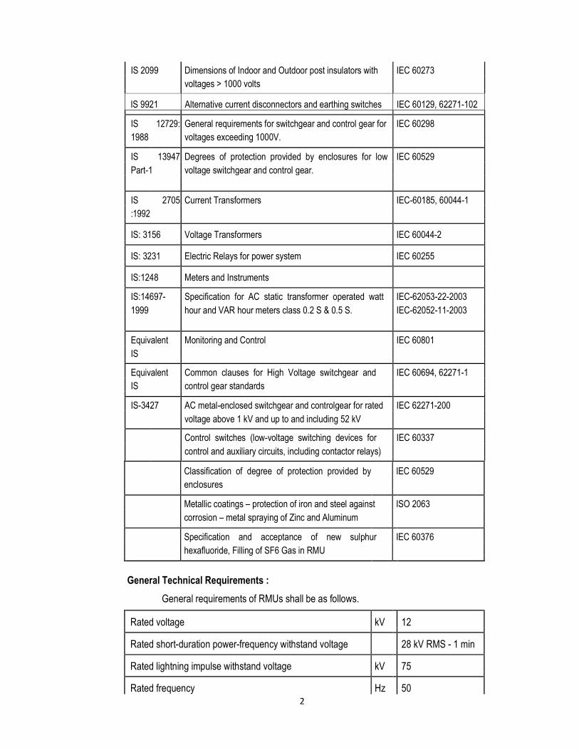
General Technical Requirements :
General requirements of RMUs shall be as follows.
Rated voltage kV 12
Rated short-duration power-frequency withstand voltage 28 kV RMS - 1 min
Rated lightning impulse withstand voltage kV 75
Rated frequency Hz 50
3
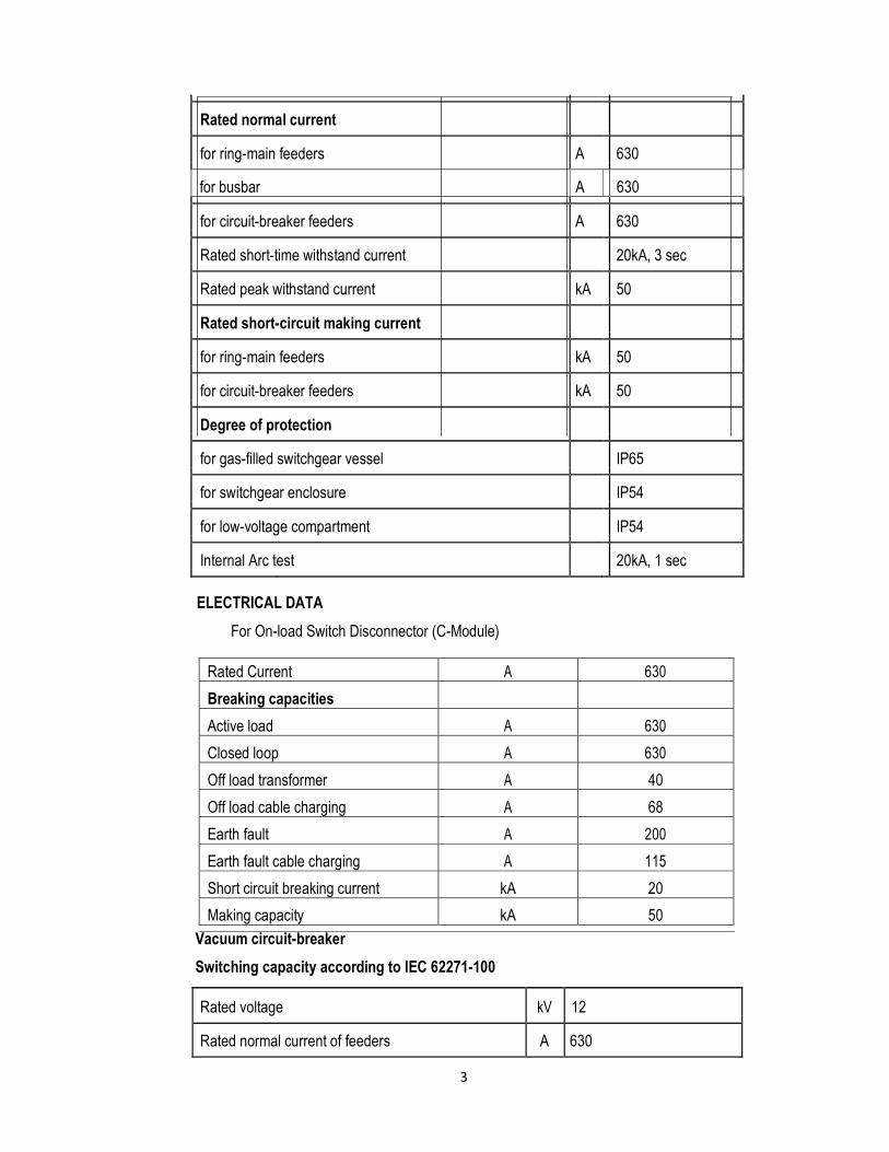
Rated normal current
for ring-main feeders A 630
for busbar A 630
for circuit-breaker feeders A 630
Rated short-time withstand current 20kA, 3 sec
Rated peak withstand current kA 50
Rated short-circuit making current
for ring-main feeders kA 50
for circuit-breaker feeders kA 50
Degree of protection
for gas-filled switchgear vessel IP65
for switchgear enclosure IP54
for low-voltage compartment IP54
Internal Arc test 20kA, 1 sec
ELECTRICAL DATA
For On-load Switch Disconnector (C-Module)
Rated Current A 630
Breaking capacities
Active load A 630
Closed loop A 630
Off load transformer A 40
Off load cable charging A 68
Earth fault A 200
Earth fault cable charging A 115
Short circuit breaking current kA 20
Making capacity kA 50 Vacuum circuit-breaker Switching capacity according to IEC 62271-100
Rated voltage kV 12
Rated normal current of feeders A 630
4
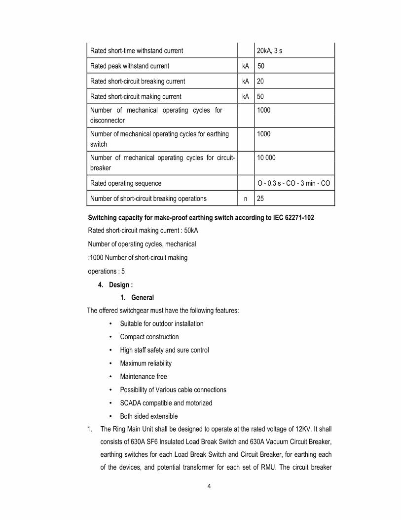
Rated short-time withstand current 20kA, 3 s
Rated peak withstand current kA 50
Rated short-circuit breaking current kA 20
Rated short-circuit making current kA 50
Number of mechanical operating cycles for 1000
disconnector
Number of mechanical operating cycles for earthing 1000
switch
Number of mechanical operating cycles for circuit- 10 000
breaker
Rated operating sequence O - 0.3 s - CO - 3 min - CO
Number of short-circuit breaking operations n 25
Switching capacity for make-proof earthing switch according to IEC 62271-102 Rated short-circuit making current : 50kA
Number of operating cycles, mechanical
:1000 Number of short-circuit making
operations : 5
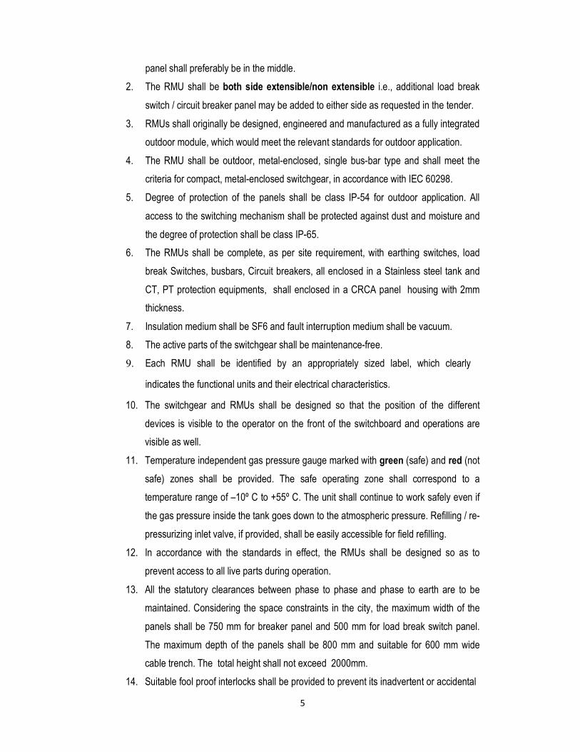
4. Design :
1. General The offered switchgear must have the following features:
• Suitable for outdoor installation
• Compact construction
• High staff safety and sure control
• Maximum reliability
• Maintenance free
• Possibility of Various cable connections
• SCADA compatible and motorized
• Both sided extensible
1. The Ring Main Unit shall be designed to operate at the rated voltage of 12KV. It shall
consists of 630A SF6 Insulated Load Break Switch and 630A Vacuum Circuit Breaker,
earthing switches for each Load Break Switch and Circuit Breaker, for earthing each
of the devices, and potential transformer for each set of RMU. The circuit breaker
5
panel shall preferably be in the middle.
2. The RMU shall be both side extensible/non extensible i.e., additional load break
switch / circuit breaker panel may be added to either side as requested in the tender. 3. RMUs shall originally be designed, engineered and manufactured as a fully integrated
outdoor module, which would meet the relevant standards for outdoor application. 4. The RMU shall be outdoor, metal-enclosed, single bus-bar type and shall meet the
criteria for compact, metal-enclosed switchgear, in accordance with IEC 60298. 5. Degree of protection of the panels shall be class IP-54 for outdoor application. All
access to the switching mechanism shall be protected against dust and moisture and
the degree of protection shall be class IP-65. 6. The RMUs shall be complete, as per site requirement, with earthing switches, load
break Switches, busbars, Circuit breakers, all enclosed in a Stainless steel tank and
CT, PT protection equipments, shall enclosed in a CRCA panel housing with 2mm
thickness. 7. Insulation medium shall be SF6 and fault interruption medium shall be vacuum. 8. The active parts of the switchgear shall be maintenance-free. 9. Each RMU shall be identified by an appropriately sized label, which clearly
indicates the functional units and their electrical characteristics.
10. The switchgear and RMUs shall be designed so that the position of the different
devices is visible to the operator on the front of the switchboard and operations are
visible as well. 11. Temperature independent gas pressure gauge marked with green (safe) and red (not
safe) zones shall be provided. The safe operating zone shall correspond to a
temperature range of –10º C to +55º C. The unit shall continue to work safely even if
the gas pressure inside the tank goes down to the atmospheric pressure. Refilling / re-
pressurizing inlet valve, if provided, shall be easily accessible for field refilling. 12. In accordance with the standards in effect, the RMUs shall be designed so as to
prevent access to all live parts during operation. 13. All the statutory clearances between phase to phase and phase to earth are to be
maintained. Considering the space constraints in the city, the maximum width of the
panels shall be 750 mm for breaker panel and 500 mm for load break switch panel.
The maximum depth of the panels shall be 800 mm and suitable for 600 mm wide
cable trench. The total height shall not exceed 2000mm.
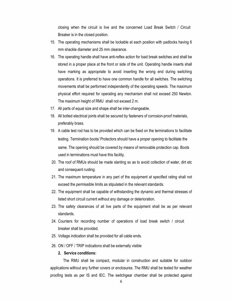
14. Suitable fool proof interlocks shall be provided to prevent its inadvertent or accidental
6
closing when the circuit is live and the concerned Load Break Switch / Circuit
Breaker is in the closed position. 15. The operating mechanisms shall be lockable at each position with padlocks having 6
mm shackle diameter and 25 mm clearance. 16. The operating handle shall have anti-reflex action for load break switches and shall be
stored in a proper place at the front or side of the unit. Operating handle inserts shall
have marking as appropriate to avoid inserting the wrong end during switching
operations. It is preferred to have one common handle for all switches. The switching
movements shall be performed independently of the operating speeds. The maximum
physical effort required for operating any mechanism shall not exceed 250 Newton.
The maximum height of RMU shall not exceed 2 m.
17. All parts of equal size and shape shall be inter-changeable. 18. All bolted electrical joints shall be secured by fasteners of corrosion-proof materials,
preferably brass. 19. A cable test rod has to be provided which can be fixed on the terminations to facilitate
testing. Termination boots/ Protectors should have a proper opening to facilitate the
same. The opening should be covered by means of removable protection cap. Boots
used in terminations must have this facility. 20. The roof of RMUs should be made slanting so as to avoid collection of water, dirt etc
and consequent rusting. 21. The maximum temperature in any part of the equipment at specified rating shall not
exceed the permissible limits as stipulated in the relevant standards. 22. The equipment shall be capable of withstanding the dynamic and thermal stresses of
listed short circuit current without any damage or deterioration. 23. The safety clearances of all live parts of the equipment shall be as per relevant
standards. 24. Counters for recording number of operations of load break switch / circuit
breaker shall be provided. 25. Voltage indication shall be provided for all cable ends.
26. ON / OFF / TRIP indications shall be externally visible
2. Service conditions:
The RMU shall be compact, modular in construction and suitable for outdoor
applications without any further covers or enclosures. The RMU shall be tested for weather
proofing tests as per IS and IEC. The switchgear chamber shall be protected against
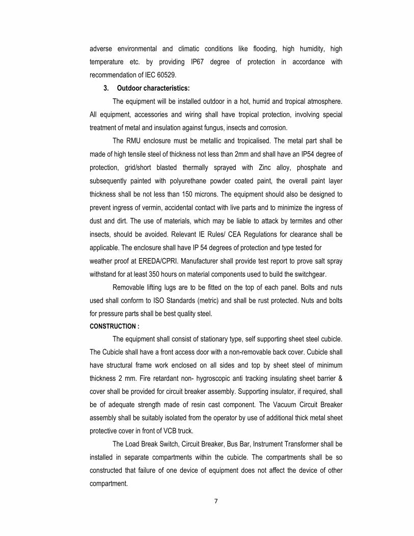
7
adverse environmental and climatic conditions like flooding, high humidity, high
temperature etc. by providing IP67 degree of protection in accordance with
recommendation of IEC 60529.
3. Outdoor characteristics:
The equipment will be installed outdoor in a hot, humid and tropical atmosphere.
All equipment, accessories and wiring shall have tropical protection, involving special
treatment of metal and insulation against fungus, insects and corrosion.
The RMU enclosure must be metallic and tropicalised. The metal part shall be
made of high tensile steel of thickness not less than 2mm and shall have an IP54 degree of
protection, grid/short blasted thermally sprayed with Zinc alloy, phosphate and
subsequently painted with polyurethane powder coated paint, the overall paint layer
thickness shall be not less than 150 microns. The equipment should also be designed to
prevent ingress of vermin, accidental contact with live parts and to minimize the ingress of
dust and dirt. The use of materials, which may be liable to attack by termites and other
insects, should be avoided. Relevant IE Rules/ CEA Regulations for clearance shall be
applicable. The enclosure shall have IP 54 degrees of protection and type tested for
weather proof at EREDA/CPRI. Manufacturer shall provide test report to prove salt spray
withstand for at least 350 hours on material components used to build the switchgear.
Removable lifting lugs are to be fitted on the top of each panel. Bolts and nuts
used shall conform to ISO Standards (metric) and shall be rust protected. Nuts and bolts
for pressure parts shall be best quality steel. CONSTRUCTION :
The equipment shall consist of stationary type, self supporting sheet steel cubicle.
The Cubicle shall have a front access door with a non-removable back cover. Cubicle shall
have structural frame work enclosed on all sides and top by sheet steel of minimum
thickness 2 mm. Fire retardant non- hygroscopic anti tracking insulating sheet barrier &
cover shall be provided for circuit breaker assembly. Supporting insulator, if required, shall
be of adequate strength made of resin cast component. The Vacuum Circuit Breaker
assembly shall be suitably isolated from the operator by use of additional thick metal sheet
protective cover in front of VCB truck.
The Load Break Switch, Circuit Breaker, Bus Bar, Instrument Transformer shall be
installed in separate compartments within the cubicle. The compartments shall be so
constructed that failure of one device of equipment does not affect the device of other
compartment.
8
Meters, Lamps, Switches shall be flush mounting type and shall be installed in
easy accessible position within the appropriate chamber on the front of the cubicle. All
fixing bolts, screws etc. appearing on the panel shall be so arranged as to present a neat
appearance. Door hinges shall be concealed type.
5. Mounting :
The equipment shall be mounted on base channels with anchor bolt holes for
installation in a concrete plinth. The RMU shall be suitable for mounting on a trench. The
RMU shall be complete with all necessary supporting frame works, Nuts and bolts etc. for
securing the same to the plinth.
6. Extensiblity
The whole switchgear (RMU) should be suitable for extension on both the sides,
with separate bushings for left and right extensibility, located on both the sides on the
upper part of the tank.
Extensible bus-bar bushings on the roof or rear or bottom are not acceptable as
they increase the dimensions of the switchgear during extension.
The exetensible Busbars should be plug-in/push on type to facilitate easy and fast
connection and installation.
Bolted type extensible busbars are not acceptable, except for the existing RMU
add on modules.
Switchgear installation, extension or panel replacement shall be possible without
gas work.
They should be designed in such a way that after connection the Busbars are not
visible / exposed to the atmosphere.
The gap between the RMU on connection should be minimum, preferably 10mm.
Addition of Interconnecting busbars should not exceed the dimension of the
complete switchgear.
7. Stainless Steel metallic Tank :
The switchgear and busbar shall be contained in a stainless steel enclosure as
per IS, filled with SF6 gas, so as to protect against adverse environmental and climatic
conditions. The enclosure should meet the "sealed pressure system" criterion in
accordance with the IEC 60298 standard (i.e. a system for which no handling of gas is
required throughout the 30 years of service life), so that refilling is not required. In addition,
manufacturer shall confirm that maximum leakage rate is lower than 0.1 % per year.
Temperature compensated SF6 gas pressure indication system shall be provided in RMUs

9
for giving early warning of pressure loss. All live parts except for the cable connection shall
be insulated with SF6 enclosure. The tank shall be made of stainless steel material
conforming to IP 67 degree of protection and the thickness shall be not be less than 2mm
and also shall withstand the pressure test as per standards.
8. Dielectric medium:
SF6 gas is the preferred dielectric medium for MV RMUs. SF6 gas used for the
filling of the RMU shall be in accordance with IEC 60376. It is preferable to have an
absorption material in the tank to absorb the moisture from the SF6 gas and to regenerate
the SF6 gas following arc interruption.
9. Load Break Switches :
The Load Break Switches shall be maintenance-free, with breaking in low pressure
SF6 gas. Ring switches shall be full load break and fault-making type. Ring switches shall
be designed for interrupting full rated current, small inductive or capacitive currents
involved in disconnecting of unloaded transformers, cables or overhead lines. It shall be
suitable for full fault-making current, simultaneously for 3 poles, by a common shaft.
Ring switch shall consist of a moving contact assembly with three positions; ‘ON’/
closed, ‘OFF’ /open-disconnected, and ‘Earth’ and will be constructed in such a way that
natural interlocking prevents unauthorized operations. Two independent manual operating
mechanisms for ring and earth switches are also acceptable. The design shall prevent
simultaneous closing of the main switch contacts and the earth switch contacts. The earth
switch contacts shall be designed to close into a fault and shall have the same short circuit
capacity as the main contacts. The switches shall be fully mounted and inspected in the
factory.
LBS shall be operated by 24V DC operated motor ( possible to operate manualy,
without removal of motor ). The switches shall be of the "increased operating frequency" in
accordance with IEC 60265-1. The switch and earthing switch operating mechanism shall
have a mechanical endurance of at least 1000 operations.
The switching operation shall be manual by means of an operating handle and
independent fast acting operating mechanism. Closing and opening speeds of the switch
shall be independent of the speed with which the operating handle is moved.
Ring switch operating mechanism shall have provision for geared motor
mechanism and associated closing and opening coils with necessary contactors for remote
and future tele-control operations in the distribution network.
The position of the power contacts and earthing contacts shall be clearly visible on
10
the front of the switchboard with the help of mechanical indicator. The position indicator
shall provide positive contact indication in accordance with IEC 60265-1 standard. In
addition, manufacturer shall prove reliability of indication in accordance with IEC 60129.
10. Circuit Breakers :
Circuit breaker shall be of fixed type. It shall have SF6 gas as insulation medium
and vacuum as interruption medium. The circuit breaker shall be maintenance-free. The
duty of the circuit breaker shall involve satisfactory interruption of short circuit currents as
listed in the specification. The breaker shall be capable of interruption of low reactive
current (lagging/leading) without undue over voltage.
The circuit breaker shall withstand system voltage at atmospheric gas pressure.
The circuit breaker can be operated safely (load make/break) at atmospheric gas pressure.
The circuit breakers shall have at least 2 positions: open-disconnected and closed
and shall be constructed in such a way that interlocking system prevents all undesired
operations. The earth switch shall be mechanically interlocked with the isolators/ breakers
to prevent any unauthorized operation. They shall be fully mounted and factory inspected.
Circuit breaker shall be designed to open, close and trip by local push buttons,
remote signals and tripping through protective relay circuit. Local and remote operation
selection shall be by a selector switch on the front panel.
Circuit breaker shall be provided with manual and electrical switching operation.
An operating mechanism can be used to manually close the circuit breaker and charge the mechanism. It shall be fitted with a local system for manual tripping by an
integrated push button. There will be no automatic re-closing.
Geared motor mechanism for spring charging and associated closing and opening
coils with necessary contactors for remote and tele-control operations shall be included.
Earthing of circuit breaker shall be by means of a switch with same fault level
capacity of the breaker.
Operating mechanism shall be fast acting and independent of the operator action
when operating manually and shall indicate the following positions:
• Circuit breaker ON and OFF
• Off-Load Isolator ON and OFF
• Earthing ON and OFF
The circuit breaker panel shall be equipped with an off-load isolator switch, and it
shall be fully interlocked with the circuit breaker.
The position of the power and earthing contacts shall be clearly visible on the front

11
of the switchboard. The position indicator shall provide positive contact indication in
accordance with IEC 60265-1 standard. In addition, manufacturer shall prove reliability of
indication in accordance with IEC 60129.
The circuit breaker shall be associated with an integrated protection unit that will
operate without any auxiliary power supply for Over Current, Short Circuit and Earth Fault
protection using Class 5P10, epoxy cast resin type CTs, setting range of 5A to 80A.
11. Main Contacts
The main contacts shall have adequate area and contact pressure for carrying
rated continuous and short time current without excessive heating liable to cause pitting
and welding.
The breakers may be provided with silver plated contacts, if necessary, to meet
the requirement of IS:13118/IEC56 where higher temperature rise is permitted with silver
plated contacts. The quantity of silver facing shall be such that after carrying out one tenth
of total number of operations specified for mechanical endurance tests, there is still
continuous layer of silver on contacts.
12. Bus Bar
Switchgear (Load Break Switch, Vacuum Circuit breakers etc.) and control gear
(CTs, PTs, relays etc.) shall be mounted on the same Kiosk. Bus bars shall be air insulated
with PVC insulation/sleeves on electrostatic powder coating. The bus bars should be of
electrolytic high grade copper with permissible limits of current density. Size of the bus
bars and current density should be specified in the offer. The bus bars conductor shall
conform to IS 8084 and 3427 and shall be rated for 630 A. It shall withstand the
mechanical stresses of the rated short circuit current.
13. Earthing :
The cables shall be earthed by an earthing switch with short-circuit making
capacity, in compliance with IEC 60129 standard. The earthing switch can only be
operated when the main Load Break Switch/ Circuit Breaker is open. The earthing switch
shall be fitted with its own / common operating mechanism and manual closing shall be
driven by a fast-acting mechanism, independent of operator action. Mechanical interlocking
systems shall prevent access to the operating shaft to avoid all operator errors such as
closing the earthing switch when the load switches are closed.
All ring main units (RMUs) shall have a special earth bar with a sectional area of
not less than 120sq.mm. Copper run along the whole of metal enclosed switch structure,
each end being connected to the main earthing system where metal cases are used on

12
instruments these shall be connected to this bar by conductors of not less than 16 sq.mm
section. There shall be continuity between the metallic parts of the switchboard and armour
of cables so that there is no electric field pattern in the surrounding air, thereby ensuring
the safety of people. That is, all the power cables shall be suitably glanded to the
equipment while termination.
In addition, a terminal having M12 stud and nut shall be provided in the back of the
panel with clear grounding mark.
14. HV Bushings :
The bushing should be conveniently located for working with cables specified, and
allow for the termination of these cables in accordance with the instructions of
Manufacturers. The profiles of the cable connection bushing shall be in compliance with
EN-50181/DIN-47636 standards.
15. Cable termination in RMUs :
Cable termination for Load Break Switches and Circuit Breakers shall be Heat
Shrinkable/ Push On type suitable for 3Core x 300sq.mm XLPE cable. A cable test rod has
to be provided which can be fixed on the terminations to facilitate testing. Termination
boots/Protectors should have a proper opening to facilitate the same. The opening should
be covered by means of removable protection cap.
Type of cable box : Air insulated
Phase to phase clearance mm 147
Phase to earth clearance mm 110
Phase to earth over insulator surface mm 120
(creepage distance)
Type of cable termination suited : Heat shrink / Push on
(Raychem or equivalent)
16. 66 Nos of 3C x 300 Sqmm XLPE, Heat Shrinkable Cable end kits for RMU’s shall be supplied along with RMU, without additional cost.
1. Cable compartments
a) Termination in the ring switches and circuit breaker units shall be dry-type inside
cable compartment suitable for accepting three core Aluminum XLPE insulated cables of
outside diameter of 70-100 mm. Each cable box shall have a bottom plate and cable
clamp. Bottom plate shall be in two halves with cable entry hole of 110 mm diameter
13
equipped with rubber bushing. Cable clamp shall be detachable semi-circular halves
suitable to hold the cable inside the cable box without cable glands.
b) Cable shall be terminated using single hole cable lugs suitable for bolt size of
M16. Cable termination shall be by means of bolted connection on cable bushing with
heat/cold shrinkable or screened pre-moulded termination with right angle/straight boots.
Plug-in type termination shall not be used.
c) Cable bushing shall be complete with brass fasteners (nuts, bolts and washers).
d) Vertical distance from the top of cable clamp to the centerline of cable bushings
shall be suitable for all type of terminations. The clearances in the ring and Tee-Off cable
compartment shall be sufficient for cable handling for termination applications.
e) The cable connection compartments must be fitted with front covers to the front.
The front covers must be integrated in the comprehensive interrogator interlocking system.
f) The cable doors should be removable/detachable type so as to facilitate easy
connection of cables and not to allow any hindrance to the maintenance staff while doing
maintenance. The design of the cable compartments shall be such that their covers with
sidewalls shall be removed to have full access during cable termination. Removal and
installation of cable compartment covers shall be with minimum number of bolts.
g) The cable connection compartment shall be arc resistant as per IEC 62271-200
amended up-to-date. The internal arc fault test on cable box shall be carried out for 11 kV
system for 20 kA for 1 second. The clearance between phase to phase and phase to earth
shall be as per IEC 61243 – 5 amended up-to- date.
No insulating material on metal surface of the cable box is allowed to ensure arc
proof resistance in the cable connection compartment
2. Cable Entry :
The cable termination access for the Load break Switch or Vacuum circuit breaker
should be from the front/side. Termination access from the rear is not acceptable.
Necessary Right angle Boot should be supplied to the cable terminations. Compound filled
cable boxes are not acceptable. The cable termination and gland arrangements shall be
appropriate for the type and style of cables used at the time.
3. Cable clamps :
A non Ferro-magnetic cable clamp arrangement for 3 core XLPE cables must be
provided for all cables terminated on the RMU. Cable shall be terminated by properly
glanding in the base plate of the RMU.
The ring main units must be equipped with outer cone connection bushings with
14
M16 – inside thread.
The connecting points of each outgoing feeder must be horizontally situated in one
level at a suitable height from the bottom line of the unit, for easy connection.
The cable brackets inside the cable connecting compartments must be vertically
and horizontally adjustable.
5. General stipulations regarding the design and development of
switchgear
5.1.1 Safety of people:
Manufacturer shall provide type test report to prove compliance with IEC 60298.
The degree of safety of persons against hazardous approach to live parts and moving
parts shall be provided strictly as per latest safety standards.
Proper sealing for the safety against entrance of small animals/ insects/ rodents
into the compartment shall be provided.
5.1.2 Over-pressure Release
In order to ensure maximum personal safety, Ring Main Unit shall be designed to
withstand any overpressure due to an internal fault by rupture of a gas escape membrane
located at the rear or bottom of the enclosure. The gas shall be led out through a flap in the
rear panel to the bottom of the enclosure.
Any accidental overpressure inside the sealed chamber will be limited by the
opening of a pressure-release device in such a way that the released gas shall not affect
the operator. Partition plate shall be provided between cable compartment and pressure
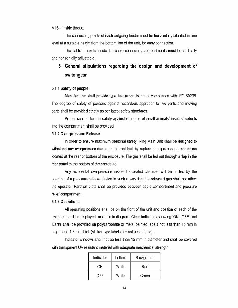
relief compartment. 5.1.3 Operations
All operating positions shall be on the front of the unit and position of each of the
switches shall be displayed on a mimic diagram. Clear indicators showing ‘ON’, OFF’ and
‘Earth’ shall be provided on polycarbonate or metal painted labels not less than 15 mm in
height and 1.5 mm thick (sticker type labels are not acceptable).
Indicator windows shall not be less than 15 mm in diameter and shall be covered
with transparent UV resistant material with adequate mechanical strength.
Indicator Letters Background
ON White Red
OFF White Green
15
Earth Black Yellow
5.1.4 Cable Testing Facility
Ring switches shall have test bushings or test probe insertion facility for high
voltage and current injection tests for the cables terminated on ring switches.
Disconnection of cables for testing purposes is not acceptable. Where there is no provision
for testing the cable without opening the door or cover, opening of door or cover should not
be possible unless the Earthing switch is closed (as per IEC 298 Clause 5.102.4). However
it must be possible to open the Earthing switch when the door is opened for cable testing.
Internal faults in any compartment such as arcing to earth, unsuccessful breaking
operation, shall not affect the operators standing in front of the switchgear assembly. All
design arrangements to avoid such risks shall be taken. 5.1.5 Interlocking :
Every switching device must have its own drive. The plug-in holes or the holes for
drive access must be included in the interrogator interlocking system of the switchgear.
Mechanical type interlocks shall forbid access to the switchgear compartment if the
following conditions are not fulfilled.
i) The switching device (load break switch / circuit breaker) is in the open position.
ii) The earthing switch is in the closed position.
iii) Any conducting parts, which extend outside the compartment, are earthed.
In addition to the interlocking provisions that prevent access into compartments,
the following interlocking shall also be provided to make the following operations
impossible:
a) Operation of load break/circuit breaker switch cannot be performed when the
i. Cable compartment is open.
ii Load breaks switch/circuit breaker is padlocked.
iii Earthing switch is in the “closed” position.
b) Operation of the ring switch or circuit breaker directly from ‘ON’ to ‘Earth’ or from
‘Earth’ to ‘ON’.
The following additional requirements apply if the unit offered has two independent
manual operating mechanisms for ring and earth switches:
• Operation of the ‘Earth ON / Earth OFF’ mechanism of earth switch unless
the ‘ON/OFF’ mechanism of ring switch is in the ‘OFF’ position.
• Operation of the ‘ON/OFF’ mechanism of ring switch unless the ‘Earth ON
16
/ Earth OFF’ mechanism of earth switch is in the ‘Earth OFF’ position.
c) Opening of the cable test cover without the associated ring switch being in the
‘Earth’ position.
d) Closing ring switch to ‘ON’ with the test plug inserted and /or the cover open.
e) Insertion or withdrawal of the test plugs with the switch in any position other than
‘Earth’ position.
f) Opening of cable boxes without the associated ring switch or breaker in the ‘Earth’
position.
g) Opening the off-load isolator switch unless the circuit breaker is in OFF position.
h) Closing the circuit breaker unless the off-load isolator switch is in ON position. 5.1.6 Padlocking facilities:
The load break switch, circuit breakers and earthing switches can be locked in the
open or closed position by 1 to 3 padlocks 6 to 8mm in diameter.
5.1.7 Voltage indicator device and Phase comparators:
The live status of the cable terminated in the RMU shall be indicated by suitable
voltage indicator device mounted on the front panel of the RMU to indicate whether or not
there is voltage in the cables. In addition, voltage indicator shall be provided on the free
connection side of the busbar for end panel.
Three inlets shall be provided to check the synchronization of phases. This device
shall be in compliance with IEC 61958 standard. Verification of correct terminal-phase
connections shall be possible by means of a phase comparison test unit.
Built-in push-button or continuous indication without push-button type neon voltage
indicators shall be provided together with low voltage hot phasing facility on ring switches
and circuit breaker panels. The lamps shall be powered by bushing type capacitive voltage
dividers. Internal wiring in cable boxes shall be covered with heat resistant tape/tube, to
protect it against flame temperature of gas torch during the cable termination. 5.1.8 Operating lever:
All manual operations will be carried out on the front of the switchboard. The
operating handle shall have anti-reflex action for load break switches and shall be stored in
a proper place at the front or side of the unit. Operating handle inserts shall have marking
as appropriate to avoid inserting the wrong end during switching operations. It is preferred
to have one common handle for all switches.
The switching movements shall be performed independently of the operating
speeds. An anti-reflex mechanism on the operating lever shall prevent any attempts to
17
reopen immediately after closing of the switch or earthing switch. The maximum physical
effort required for operating any mechanism shall not exceed 250Newton. The maximum
height of the mechanism operating access shall not exceed 1.5 m.
5.1.9 Earth Fault & Short Circuit Indicator / Fault Passage Indicator (FPI)
All ring-main feeders shall be equipped with a 3-phase short-circuit and earth-fault
indicator. Earth fault indicator, operated by core-balance type current transformer, shall be
located near and outside cable box/termination with indicator visible from front and with
automatic reset. They shall be provided with bright LED’s / Flag Indicators, which shall be
clearly visible all the time. They shall have the following resetting facilities:
• Manual reset
• Resetting after a set time duration
• Remote reset
In case of a momentary fault in which the fault sensor picks up, but the breaker
does not trip, then after 2 seconds the system shall automatically reset and shall revert to
the monitoring mode. Subsequent to an actual fault, the system shall reset automatically as
soon as the supply is re-established after isolating the faulty portion.
The fault sensing devices should function properly irrespective of the earth
resistance of the location. FPI shall be installed on all the limbs.
It should be possible to test these indicators at site through “Test” push button.
Three-pin plug for testing of FPI by primary current injection shall be provided in separate
compartment with screwed cover, below the FPI housing. Fault current indication system
shall have local and remote reset facility and compatible for SCADA applications through
RTU. It shall be with two auxiliary contacts, one for light signal and the other for remote
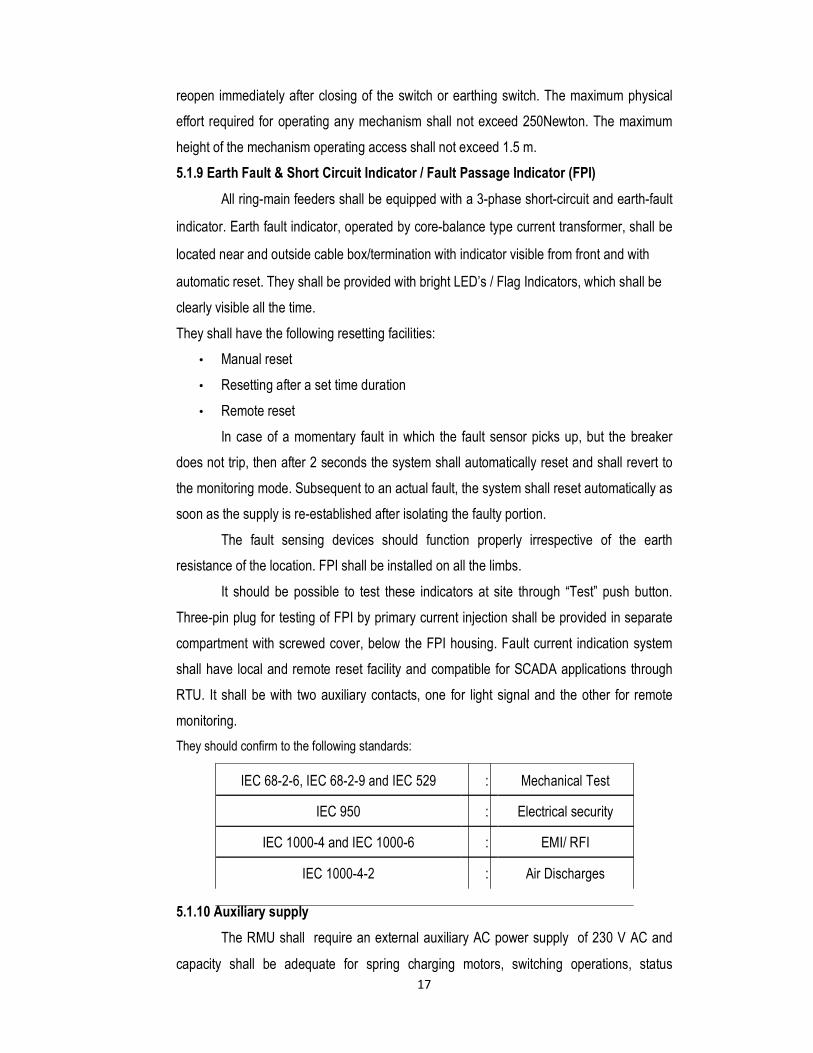
monitoring. They should confirm to the following standards:
IEC 68-2-6, IEC 68-2-9 and IEC 529 : Mechanical Test
IEC 950 : Electrical security
IEC 1000-4 and IEC 1000-6 : EMI/ RFI
IEC 1000-4-2 : Air Discharges 5.1.10 Auxiliary supply
The RMU shall require an external auxiliary AC power supply of 230 V AC and
capacity shall be adequate for spring charging motors, switching operations, status
18
indications, protective relays, necessary contactors for control and monitoring of ring
switches and circuit breaker panels and rectifier for battery charger.
Enough space and provision should be provided in the cable compartment and
cable terminations to accommodate ring type CT’s
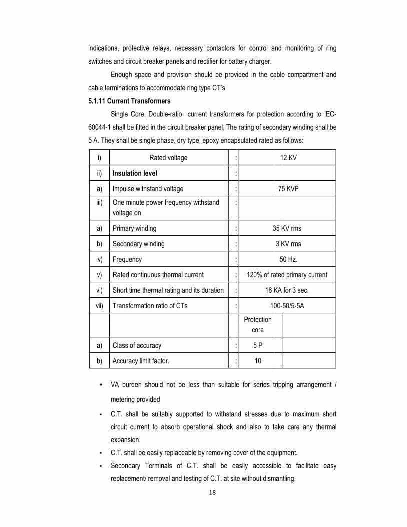
5.1.11 Current Transformers
Single Core, Double-ratio current transformers for protection according to IEC-
60044-1 shall be fitted in the circuit breaker panel, The rating of secondary winding shall be
5 A. They shall be single phase, dry type, epoxy encapsulated rated as follows:
i) Rated voltage : 12 KV
ii) Insulation level :
a) Impulse withstand voltage : 75 KVP
iii) One minute power frequency withstand :
voltage on
a) Primary winding : 35 KV rms
b) Secondary winding : 3 KV rms
iv) Frequency : 50 Hz.
v) Rated continuous thermal current : 120% of rated primary current
vi) Short time thermal rating and its duration : 16 KA for 3 sec.
vii) Transformation ratio of CTs : 100-50/5-5A
Protection
core
a) Class of accuracy : 5 P
b) Accuracy limit factor. : 10
• VA burden should not be less than suitable for series tripping arrangement /
metering provided
• C.T. shall be suitably supported to withstand stresses due to maximum short
circuit current to absorb operational shock and also to take care any thermal
expansion.
• C.T. shall be easily replaceable by removing cover of the equipment.
• Secondary Terminals of C.T. shall be easily accessible to facilitate easy
replacement/ removal and testing of C.T. at site without dismantling.

19
• C.T. ratio change over link shall be provided on the Terminal Board at the front
side of the terminal Point.
• One of the Secondary Terminal of each C.T. shall be shorted and earthed at
terminal point.
• The core shall be of grade non ageing laminated silicon steel of low hysterisis loss
and high permeability to ensure high accuracy at both normal and fault current.
The magnetising curve of C.T. shall be furnished.
• C.T. shall be provided with terminal marking, wiring diagram and rating plate as
per provision in I.S.
Required transformers ratio can be achieved in any manner, however, the current
transformers will have to satisfy the requirement of rated VA burden, Class of accuracy,
accuracy limit factor and short time thermal rating as have been specified above at all
transformation ratios.
The rating of current transformers of all classes regarding ratio error, knee point
voltage, resistance of secondary winding etc. shall have to be coordinated with the
requirement of protective relays and protection scheme without any extra cost. 5.1.12 RELAYS :
The circuit breaker shall be fitted with AC Series tripping arrangement for
operation on overload & earth fault by relays along with emergency shunt tripping from
remote. The functions of relay are Protection, control, indicating, communications and
measuring.
Specifications of Phase and Ground Over current Protective Relays with Low set
(Time Delay) and High-set (Instantaneous) Elements (50/51,50N/51N) 1. General
1.1 The relay shall be microprocessor based numerical type.
1.2 All the components, hardware, input/output devices of the relay shall comply with
relevant IEC or equivalent standards.
1.3 The relay shall use thoroughly tested software and hardware to IEC or equivalent
standards. Relay should have acquired at least two (2) years of field experience
in a major electric utility.
1.4 All the input/output units of the relay shall be capable of making/breaking
currents (with any transients) and withstand voltages (normally
intended/harmonic over voltages).
1.5 The relay shall be immune to all types of electrical and mechanical interference
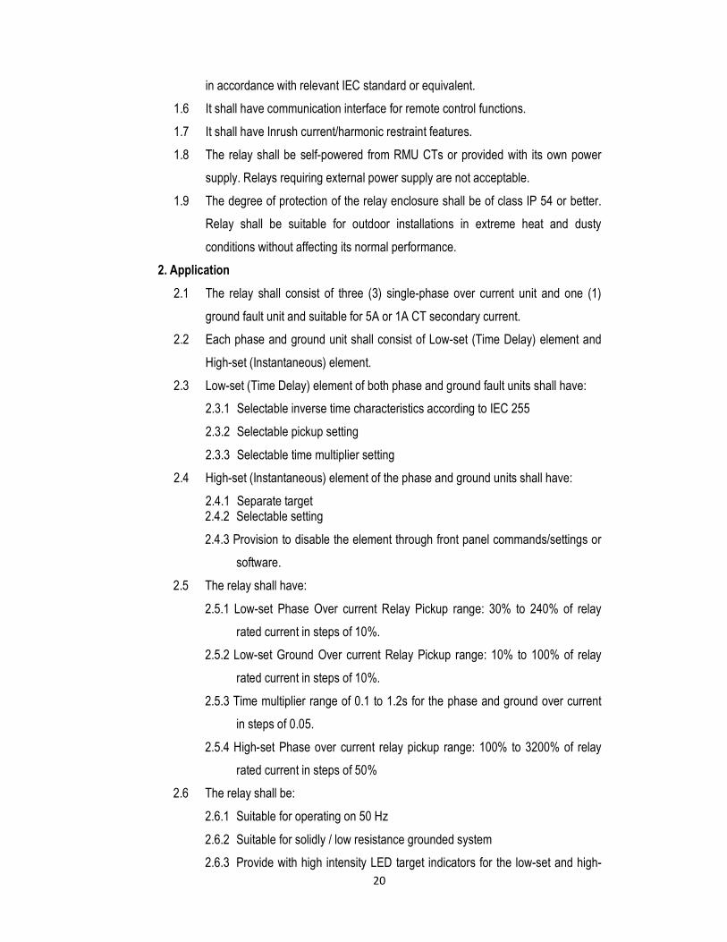
20
in accordance with relevant IEC standard or equivalent.
1.6 It shall have communication interface for remote control functions.
1.7 It shall have Inrush current/harmonic restraint features.
1.8 The relay shall be self-powered from RMU CTs or provided with its own power
supply. Relays requiring external power supply are not acceptable.
1.9 The degree of protection of the relay enclosure shall be of class IP 54 or better.
Relay shall be suitable for outdoor installations in extreme heat and dusty
conditions without affecting its normal performance.
2. Application
2.1 The relay shall consist of three (3) single-phase over current unit and one (1)
ground fault unit and suitable for 5A or 1A CT secondary current.
2.2 Each phase and ground unit shall consist of Low-set (Time Delay) element and
High-set (Instantaneous) element.
2.3 Low-set (Time Delay) element of both phase and ground fault units shall have:
2.3.1 Selectable inverse time characteristics according to IEC 255
2.3.2 Selectable pickup setting
2.3.3 Selectable time multiplier setting
2.4 High-set (Instantaneous) element of the phase and ground units shall have:
2.4.1 Separate target 2.4.2 Selectable setting
2.4.3 Provision to disable the element through front panel commands/settings or
software.
2.5 The relay shall have:
2.5.1 Low-set Phase Over current Relay Pickup range: 30% to 240% of relay
rated current in steps of 10%.
2.5.2 Low-set Ground Over current Relay Pickup range: 10% to 100% of relay
rated current in steps of 10%.
2.5.3 Time multiplier range of 0.1 to 1.2s for the phase and ground over current
in steps of 0.05.
2.5.4 High-set Phase over current relay pickup range: 100% to 3200% of relay
rated current in steps of 50%
2.6 The relay shall be:
2.6.1 Suitable for operating on 50 Hz
2.6.2 Suitable for solidly / low resistance grounded system
2.6.3 Provide with high intensity LED target indicators for the low-set and high-
21
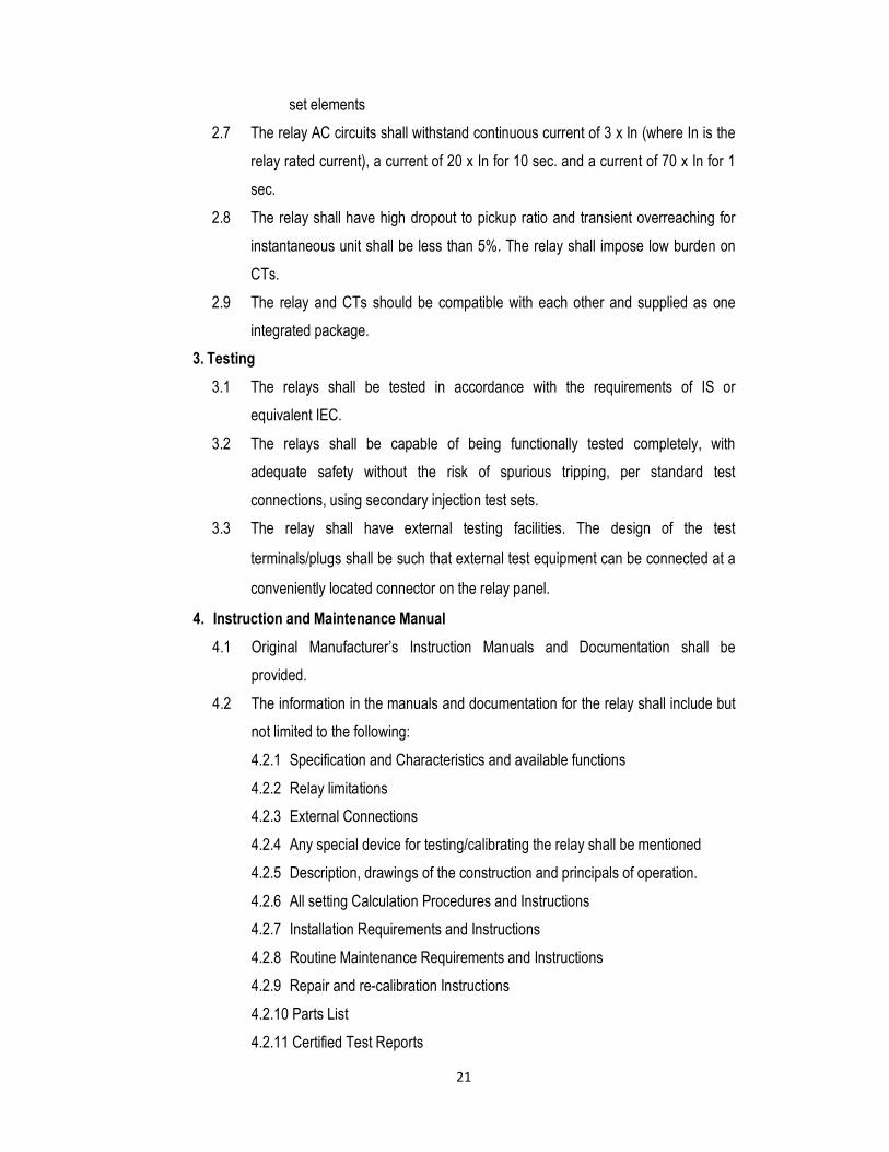
set elements
2.7 The relay AC circuits shall withstand continuous current of 3 x In (where In is the
relay rated current), a current of 20 x In for 10 sec. and a current of 70 x In for 1
sec.
2.8 The relay shall have high dropout to pickup ratio and transient overreaching for
instantaneous unit shall be less than 5%. The relay shall impose low burden on
CTs.
2.9 The relay and CTs should be compatible with each other and supplied as one
integrated package.
3. Testing
3.1 The relays shall be tested in accordance with the requirements of IS or
equivalent IEC.
3.2 The relays shall be capable of being functionally tested completely, with
adequate safety without the risk of spurious tripping, per standard test
connections, using secondary injection test sets.
3.3 The relay shall have external testing facilities. The design of the test
terminals/plugs shall be such that external test equipment can be connected at a
conveniently located connector on the relay panel.
4. Instruction and Maintenance Manual
4.1 Original Manufacturer’s Instruction Manuals and Documentation shall be
provided.
4.2 The information in the manuals and documentation for the relay shall include but
not limited to the following:
4.2.1 Specification and Characteristics and available functions
4.2.2 Relay limitations
4.2.3 External Connections
4.2.4 Any special device for testing/calibrating the relay shall be mentioned
4.2.5 Description, drawings of the construction and principals of operation.
4.2.6 All setting Calculation Procedures and Instructions
4.2.7 Installation Requirements and Instructions
4.2.8 Routine Maintenance Requirements and Instructions
4.2.9 Repair and re-calibration Instructions
4.2.10 Parts List
4.2.11 Certified Test Reports
22
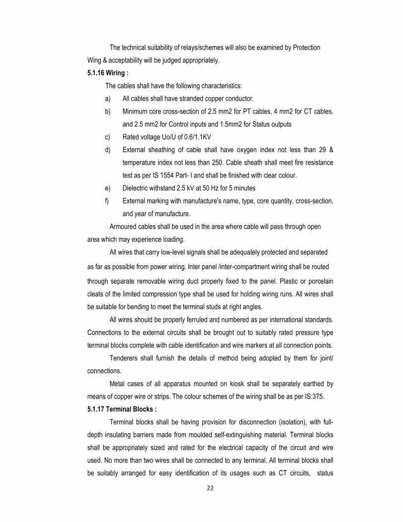
The technical suitability of relays/schemes will also be examined by Protection
Wing & acceptability will be judged appropriately.
5.1.16 Wiring :
The cables shall have the following characteristics:
a) All cables shall have stranded copper conductor.
b) Minimum core cross-section of 2.5 mm2 for PT cables, 4 mm2 for CT cables,
and 2.5 mm2 for Control inputs and 1.5mm2 for Status outputs
c) Rated voltage Uo/U of 0.6/1.1KV
d) External sheathing of cable shall have oxygen index not less than 29 &
temperature index not less than 250. Cable sheath shall meet fire resistance
test as per IS 1554 Part- I and shall be finished with clear colour.
e) Dielectric withstand 2.5 kV at 50 Hz for 5 minutes
f) External marking with manufacture's name, type, core quantity, cross-section,
and year of manufacture.
Armoured cables shall be used in the area where cable will pass through open
area which may experience loading.
All wires that carry low-level signals shall be adequately protected and separated
as far as possible from power wiring. Inter panel /inter-compartment wiring shall be routed
through separate removable wiring duct properly fixed to the panel. Plastic or porcelain
cleats of the limited compression type shall be used for holding wiring runs. All wires shall
be suitable for bending to meet the terminal studs at right angles.
All wires should be properly ferruled and numbered as per international standards.
Connections to the external circuits shall be brought out to suitably rated pressure type
terminal blocks complete with cable identification and wire markers at all connection points.
Tenderers shall furnish the details of method being adopted by them for joint/
connections.
Metal cases of all apparatus mounted on kiosk shall be separately earthed by
means of copper wire or strips. The colour schemes of the wiring shall be as per IS:375.
5.1.17 Terminal Blocks :
Terminal blocks shall be having provision for disconnection (isolation), with full-
depth insulating barriers made from moulded self-extinguishing material. Terminal blocks
shall be appropriately sized and rated for the electrical capacity of the circuit and wire
used. No more than two wires shall be connected to any terminal. All terminal blocks shall
be suitably arranged for easy identification of its usages such as CT circuits, status
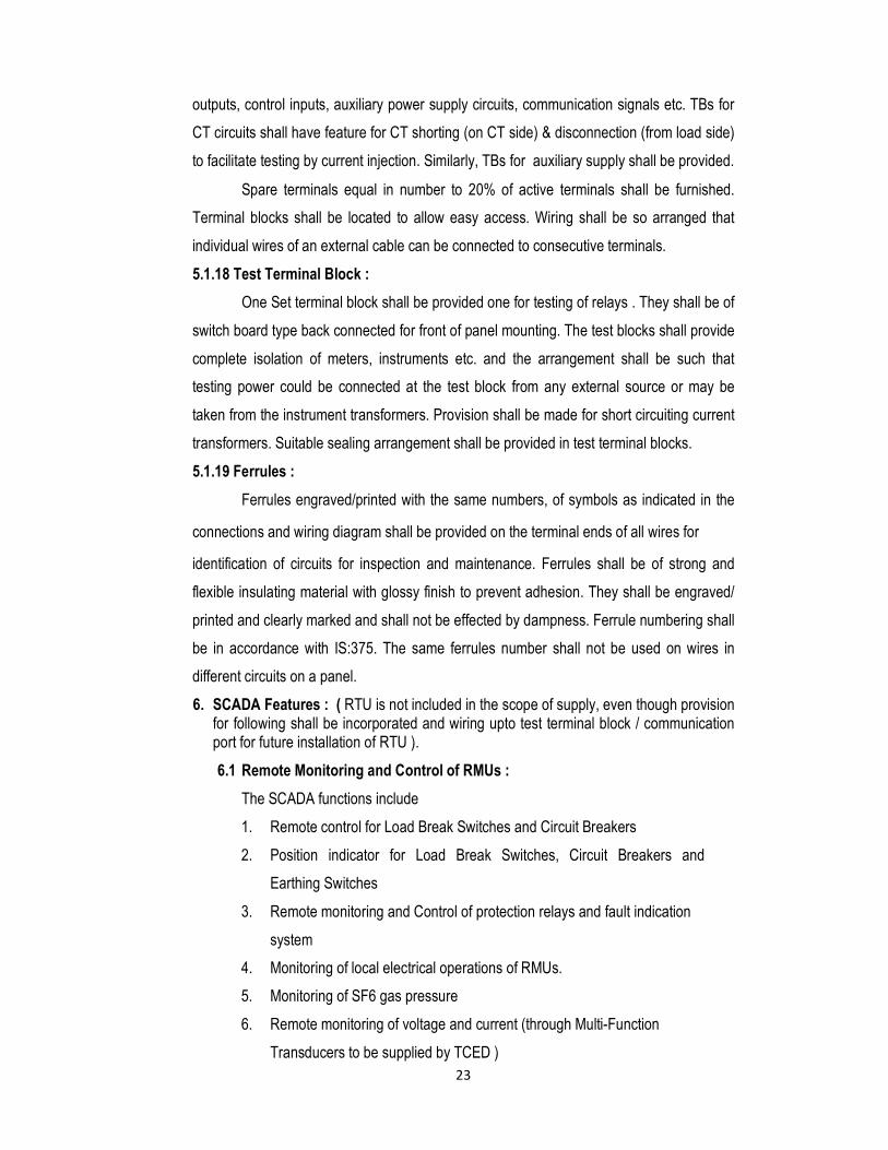
23
outputs, control inputs, auxiliary power supply circuits, communication signals etc. TBs for
CT circuits shall have feature for CT shorting (on CT side) & disconnection (from load side)
to facilitate testing by current injection. Similarly, TBs for auxiliary supply shall be provided.
Spare terminals equal in number to 20% of active terminals shall be furnished.
Terminal blocks shall be located to allow easy access. Wiring shall be so arranged that
individual wires of an external cable can be connected to consecutive terminals. 5.1.18 Test Terminal Block :
One Set terminal block shall be provided one for testing of relays . They shall be of
switch board type back connected for front of panel mounting. The test blocks shall provide
complete isolation of meters, instruments etc. and the arrangement shall be such that
testing power could be connected at the test block from any external source or may be
taken from the instrument transformers. Provision shall be made for short circuiting current
transformers. Suitable sealing arrangement shall be provided in test terminal blocks. 5.1.19 Ferrules :
Ferrules engraved/printed with the same numbers, of symbols as indicated in the
connections and wiring diagram shall be provided on the terminal ends of all wires for
identification of circuits for inspection and maintenance. Ferrules shall be of strong and
flexible insulating material with glossy finish to prevent adhesion. They shall be engraved/
printed and clearly marked and shall not be effected by dampness. Ferrule numbering shall
be in accordance with IS:375. The same ferrules number shall not be used on wires in
different circuits on a panel. 6. SCADA Features : ( RTU is not included in the scope of supply, even though provision
for following shall be incorporated and wiring upto test terminal block / communication port for future installation of RTU ).
6.1 Remote Monitoring and Control of RMUs :
The SCADA functions include
1. Remote control for Load Break Switches and Circuit Breakers
2. Position indicator for Load Break Switches, Circuit Breakers and
Earthing Switches
3. Remote monitoring and Control of protection relays and fault indication
system
4. Monitoring of local electrical operations of RMUs.
5. Monitoring of SF6 gas pressure
6. Remote monitoring of voltage and current (through Multi-Function
Transducers to be supplied by TCED )
24
7. Remote monitoring of healthiness of battery and battery charger.
6.2 Status Monitoring Outputs :
Contact Multiplying Relays (CMRs) are required to multiply the contacts of breaker,
isolators and protection relays etc. The contacts of these relays shall be used to provide
status inputs to the RTUs. The relays shall be DC operated, self reset type. The rated
voltage for relay operation shall be on 24V DC. The relay shall be able to operate for +/-
20% variation from nominal voltage. The relay shall have a minimum of two change over
contacts, out of which one shall be used for SCADA purposes. The contacts shall be rated
to carry minimum current capacity of 0.2A at 48VDC and shall provide arc suppression to
permit interruptions of an inductive load.
The relays coils shall be shunted with diodes to suppress inductive transients
associated with energizing and de-energizing of the relay coils. The relays shall conform to
the IEC 255-1-00 and IEC 255-5 requirements. The relays must be protected against the
effects of humidity, corrosion & provide with a dust tight cover. The connecting terminals
shall be screw type & legibly marked. The relays may optionally have a visual operation
indicator. The relays are to be mounted in RMU panel and therefore shall be equipped with
suitable mounting arrangements.
6.3 Motor operation of Load Break Switches and Circuit Breakers:
Closing and Opening operation of Load Break Switch/ Circuit Breaker and shunt
trip of the circuit breaker shall be done from remote.
Spring charging mechanism of the Breaker should be motorised for Local electrical
charging. The motor drives have to be integrated into the recess of the drives.
The bidder shall specify characteristic of motor operation of Load break switch &
circuit breaker. Reverse polarity protection shall be given for motors in RMUs. It should be
possible to change the manual drives of the load break switches to motorized drives at site.
Motor kit should easily be mounted in commissioned RMU at a later stage if required. All
the mechanical interlocking must also work when the load break switches are operated by
a motor drive. In case of power failure of the auxiliary voltage the manual operation of the
switching devices must be possible by means of an operating handle. Control Inputs
The control inputs from RTUs shall be used to control power system devices such
as Circuit breakers, isolator, reset relay, disable/enable any other two-state devices. A set
of control inputs shall be provided for each controllable device. The control input from the
RTU shall be used for initiating heavy duty relays for trip/close of switching devices. The
25
power requirement of relays shall be maximum 0.2A at 24 Vdc.
The contractor shall provide heavy duty relays. The relays shall be DC operated,
self reset type. The rated voltage for relay operation shall be on 24V DC. The relay shall be
able to operate for +/-20% variation from nominal voltage. The relay shall have a minimum
of two change over contacts, out of which one shall be used for telemetry purposes. The
contacts shall be rated to carry minimum current capacity of 0.2A at 48VDC. The relays
shall conform to the IEC 255-1-00 and IEC 255-5 requirements. These relay coils shall be
shunted with diodes to suppress inductive transients associated with energizing and de-
energizing of the relay coils & shall conform to the relevant IEC requirements. The relays
must be protected against the effects of humidity, corrosion & provide with a dust tight
cover. The connecting terminals shall be screw type & legibly marked. The relays may
optionally have a visual operation indicator. 6.4 Battery:
The Battery should be of reputed make with superior dry fit technology,
maintenance free suitable for Automation of RMU.
Following should be the features of the battery: -
a. 24V , 24AH type maintenance free batteries.
b. Exceptional energy storage capacity combined with long life.
c. Maintenance free (no topping up) during the whole service life.
d. Guaranteed service life for 5 years.
e. Very low gassing due to internal gas recombination.
f. Shelf life up to 2 years
g. Short recharging time.
h. Completely recyclable.
i. Should have capacity for 5 Switching operations and 48 hours of operation of
RTU / Modem / Communication for SCADA in the event of supply failure.
6.5 Battery Charger : ( 24V 25AH)
24V on line Rectifier cum battery charger of sufficient capacity to drive motors and
SCADA equipments with voltage regulation of +/-5% or less on full load. Battery charger,
offered shall be suitable for Dry fit batteries with the following technical features
1. Industrial DIN RAIL mounted battery charger.
2. Input voltage 110 V AC +/ - 20%
3. Output voltage (as per requirement for the battery above).
4. Wide output adjustment range.
26
5. Series and parallel use should be possible.
6. The battery shall recharge to 80 % of its capacity in a maximum of 15 hours
7. Batteries shall be disconnected at the manufacturer's specified minimum
voltage.
8. Battery Low' indication shall be available locally and remotely and shall
include a battery test. The indication of "Battery Low" status shall allow for a
further three RMU operations.
9. System Healthy and Power Fail indicators to be provided.
Technical specifications are to be indicated by the bidder on the battery
charger.
7. NAME, RATING, MARKING, PROPERTY PLATE, CIRCUIT LABEL, CONNECTION
DIAGRAM AND OPERATION INSTRUCTION 1. The front plate shall have IP2X degree of protection. The front shall include a clear
mimic diagram, which indicates the different functions. The position indicators shall
give a true reflection of the position of the main contacts. They shall be clearly
visible to the operator. The lever operating direction shall be clearly indicated in
the mimic diagram.
2. The manufacturer's Name & Rating plate shall include the switchboard's main
electrical characteristics and shall contain all information as per provision in the
Standards. Each switchgear shall be provided with Aluminum /Stainless steel /
Brass nameplate showing the following information indelibly marked in English:
• Manufacturer’s Name
• Country of Origin
• Type/Model
• Vendor’s Name
• Reference of specification
• Manufacturer’s Serial Number
• KSEB Purchase Order Number
• Year of Manufacture
• Voltage Rating kV
• Current Rating Amps
• BIL kV
• Short Circuit Rating / Duration kA / Sec
• Rated Frequency Hz
27
• Rated Making Current kA
• Rated Breaking Current kA
• Gross Weight kg 3. Property Plate mentioning “TCED” shall be provided.
4. Circuit label incorporating identification of ring switches and tee switch unit, Ring
Cables and outgoing Tee Cable shall be provided. 5. Ring switches and circuit breaker panels shall be provided with circuit number plates
of dimension 150 x 50 mm without inscription. Plate shall be made of three layer
traffolyte material (white/black/white) of 3 mm thickness. 6. Connection Diagram Plate shall be provided as per provision in the standards. 7. Danger plate shall be provided and installed at the front panel of the switchgear using
M5 hot dipped galvanized / stainless steel / brass fasteners (oval head rounded neck
bolts with nuts and external tooth lock washers) not removable / accessible from the
front i.e. without opening the door / front cover. The danger Board plate as per
relevant IS. 8. Operation Instruction mentioning sequential operation procedures shall have to be
displayed. 9. All terminals including Earthing terminal shall be properly marked. 10. The name, rating, marking, property plate, circuit label, connection diagram and
operation instruction shall be riveted / fixed using self threading screw. 8 Tests :
Routine tests shall be conducted on the Ring Main Units in accordance with the
latest versions of IEC. Each completely wired Ring Main Unit shall be tested to ensure that
all its protective, control and interlock systems are satisfactorily functioning in the manner
as required. The bidder shall indicate tests recommended to be carried out at site during
installation and commissioning to ensure satisfactorily performance of all the equipment
supplied.
8.1 Type tests :
The Ring Main Units shall be fully type tested as per the relevant standards
including the type tests mentioned below. The type tests must have been conducted on
11KV Ring Main Units of same type from recognized test laboratories not earlier than 5
years from the date of opening of bid. The bidder shall furnish two sets of type test reports
as per relevant standards along with the bid. Bids without the following type test reports will
be treated as non-responsive.
28
According to this specification and IEC recommendations, the following type test
certificates shall be supplied:
• Impulse withstand test
• Temperature-rise test
• Short-time withstand current test
• Mechanical operation test
• Checking of partial discharge on complete unit
• Switch, circuit breaker, earthing switch-making capacity
• Switch, circuit breaker breaking capacity
• Internal arc withstand
• Checking of degree of protection
• Salt spray withstand test
In addition, for switches, test reports on rated breaking and making capacity shall
be supplied. For earthing switches, test reports on making capacity, short-time withstand
current and peak short-circuit current shall be supplied.
8.2 Routine Tests :
The switchgear offered shall meet the routine test requirements of the standards
listed below:
8.2.1 Load break switches per IEC 60265
a) Power Frequency Voltage Tests
b) Voltage Tests on Auxiliary Circuits
c) Measurement of Resistance of Main Circuit
d) Operation Tests
e) Operation and Mechanical Endurance Tests
8.2.2 Circuit breaker per IEC 60056
a) Power Frequency Voltage Tests
b) Voltage Withstand Tests on Control and Auxiliary Circuits
c) Measurement of Resistance of Main Circuit
d) Mechanical Operating Tests
The routine tests carried out by the manufacturer shall be backed by test reports
signed by the factory's quality control department. They shall include the following:
1. Conformity with drawings and diagrams
2. Measurement of closing and opening speeds
3. Measurement of operating torque
29
4. Checking of filling pressure
5. Checking of gas-tightness
6. Checking of partial discharges on individual components
7. Dielectric testing
8. Measurement of main circuit resistance
9. Measurement of the time travel characteristics of breakers
10. Measurement of Insulation Resistance
8.3 Tests during manufacture:
The Contractor shall furnish details of tests carried out during the process of
manufacture and end inspection by the supplier to ensure the desired quality of the
equipment to be supplied. Tests as per applicable standards should be carried out in
respect of porcelain bushings, galvanization, relays and meters.
8.4 Make and type of bought out items :
The makes of all bought out items shall be acceptable if it is of "ISI Marked" or type
tested for which tenderers shall furnish attested photostat copies of ISI Certificate/type test
report not older than three years for the respective make offered along with tender.
Make / type of each relay, indicating instruments, integrating instruments, control
switch for Circuit Breaker/Trip Transfer, selector switch for Voltmeter/Ammeter, Semaphore
Indicator, indicating lamps, annunciator, Push Button, Link Type Test Terminal Block for
testing of TVM, CFL Tube, 2/3 Pin Socket with Switch etc. shall be clearly and invariably
indicated in the GTP (Guaranteed Technical Particulars), bill of material and unit price list.
Only specific make accessories shall be indicated. The word "EQUIVALENT/REPUTED
MAKE" will not be given for consideration.
8.5 Test on Bought Out Items :
The bidder must furnish type test reports as per relevant IS/ IEC along with bid to
suit the environmental conditions of our State, in respect of the relay (of the type and
design offered) which should have been type tested in NABL accredited test laboratory in
respect of such tests for which the lab has been accredited / CPRI (for Indian make
Relays) / Nationally accredited testing laboratory (for Foreign make Relays). These type
test reports should not be older than three years from the date of opening of bid. Bids
without Type Test reports will be treated as Non- Responsive.
The tenderer shall also furnish along with the tender, complete general
arrangement, schematic and outline diagrams indicating the mounting arrangement and
position of current transformers, potential transformer, terminal block etc.

30
Type of current transformers and employed shall also be clearly stated. The type
test reports of Current Transformers, Relays, Meters etc. shall be complete in all respect
as per relevant IEC/IS.
Tests are not required to be performed on bought out equipments/items like motor,
meter, relay etc. at the works of RMU manufacturer. Furnishing Test Certificate of these
items from the original equipment manufacturers shall be deemed to be satisfactory
evidence. Inspection of the tests at Sub-contractors works will be arranged by the
Contractor whenever required.
8.6 Additional Tests :
TCED reserves the right of having at contractors expenses any other tests of
reasonable nature carried out at Manufacturer’s premises, at site, or any in any other place
in addition to the aforesaid type, acceptance and routine tests, to satisfy themselves that
the material comply with the specifications.
In case of failure of any type test, the supplier is required to modify the design of
the material and the material shall be type tested again for the modified design, without any
extra cost to TCED. No delivery extension shall be given for this additional testing.
8.7 Test Reports :
Record of routine test reports shall be maintained by the Contractor at his works
for periodic inspection at his works for periodic inspection by the TCED representative. A
copy of the same shall be furnished along with each equipment.
8.8 Test facilities : Witnessing
The tests shall be carried out as per relevant standards and test certificates shall
be furnished for approval. The bidder shall indicate the details of the equipment available
with him for carrying out the various tests as per relevant standards. The bidder shall
indicate the sources of all materials. He shall indicate the name of the Supplier and make
of vacuum interrupters, relays, conductor, electrical steel laminations constructional steel
etc.
Tests as per applicable standards should be carried out in respect of porcelain
bushings, galvanization, relays and meters.
9. Information to be furnished along with the Bid : The following information shall be furnished along with the bid:
1. Completely filled in Guaranteed Technical Particulars.
2. Catalogues describing the equipment duly indicating the model.
3. Literature describing the operational.
31
10. Mandatory Spares and Tools:
Comprehensive list of manufacturer’s recommended spare parts shall be furnished
along with the bid. The quantities offered should be adequate for the initial 5 years of
operation. Firm price and delivery period shall be quoted for each item.
List of recommended special maintenance Tools and Tackles together with their
individual prices shall be furnished along with the bid.
11. Pre despatch Delivery / Training
The Supplier shall install the RMUs at the locations specified by the TCED. The
supplier shall provide training facilities before despatch at place of manufacture for atleast
2 engineers about the operation and maintenance. The training shall be for not less than 3
days with suppliers cost including Travelling, lodging, etc. Training for 4 engineers shall be
given at site.
12. Deviations: 12.1. The tenderer shall furnish, if there are any deviations in the technical terms as
per schedule. If no deviations are furnished it will be construed that the tenderer is
accepting the technical specification. Similarly if any deviations are furnished in the
specified form it will be construed that these are the only deviations and the tenderer is
accepting all other terms of the technical specification and the offer will be taken for
evaluation accordingly.
12.2 The offers of the tenders with deviations in commercial terms of the specification
are liable for rejection.
12.3. No alternate offer will be accepted.
Schedule of deviations from Technical specifications
All deviations from Technical specifications shall be filled in by the bidder clause by clause in this schedule.
Section Specification No. Clause No. Deviation Monetary
Implication
32
The bidder hereby certificate the above-mentioned are the only deviations from TCED’s Technical specifications for this bid. The bidder confirms that in the event of any data and information presenting in the bidder’s proposal and accompanying documents including drawings, catalogues etc. are at variance with the specific requirements laid out in the TCED’s Technical Specifications, then the latter shall govern and will be binding on the bidder for the quoted price.
13. Inspection:
a) The TCED representative shall, at all times, be entitled to have access to the works
and at all places of manufacture and the representative shall have full facilities for
unrestricted inspection of the Manufacturer’s works, raw materials and process of
manufacture and conducting necessary tests as detailed herein.
b) The supplier shall keep TCED informed in advance of the time of starting and of the
progress of manufacture of offered equipment in its various stages so that
arrangements can be made for inspection.
c) The supplier shall give 15 days advance intimation to enable TCED to dispute its
representative for witnessing acceptance and routine tests.
d) No material shall be dispatched from its point of manufacture before it has been
satisfactorily inspected and tested, unless the inspection is waived off by the TCED
in writing.
e). The acceptance of any quantity of material shall in no way relieve the supplier of any
of responsibilities for meeting all requirements of the specification, and shall not
prevent subsequent rejection if such material is later found to be defective. 14. Guaranteed Technical Particulars: Guaranteed Technical particulars shall be furnished by the Bidder, along with the bid. 15. Documentation:
All drawings shall conform to International Standards Organisation (ISO) ‘A’ series
of drawings sheet / Indian Standard Specifications IS:656. All drawings shall be in ink and
suitable for microfilming and a soft copy of the drawings. All dimensions and data shall be
in S.I.Units. 16. List of Drawings and Documents:
The bidder shall furnish four sets of following drawings and documents along with his
33
offer.
• Completely filled – in technical schedules
• Typical general arrangement drawings
• Type test certificates
• Quality Assurance Plan
• Experience List
• Foundation fixing drawings
• General outline drawings showing plan, elevation and end view
dimensions assembly and constructional drawings of the equipment
• Name plate and schematic drawings
• Operation manuals, leafless literature
• The successful bidder shall, within 2 weeks of the placement of order, submit 3
sets of final versions of all the above said drawings for TCED’s approval. The
TCED shall communicate his comments / approval on the drawings to the
supplier within 4 weeks. The supplier shall, if necessary, modify the drawings and
resubmit 3 copies of the modified drawings for their approval. The supplier shall
within 2 weeks submit 5 prints and 2 good quality copies of the approved
drawings for TCED’s use.
The supplier for distribution before commencement of supply shall submit 2 sets of
the type test reports, duly approved by TCED. Adequate copies of acceptance and routine
test certificates, duly approved by TCED shall accompany the dispatch consignment.
The manufacturing of the equipment shall be strictly in accordance with the
approved drawings and no deviation shall be permitted without the written approval of the
TCED. All manufacturing and fabrication work in connection with the equipment prior to the
approval of the drawing shall be at the supplier’s risk.
One set of nicely printed bound volumes of operation, maintenance, and erection
manuals and approved drawings in English Language shall be supplied along with each
circuit breaker, in addition to the five sets to be sent directly to TCED.
Approval of drawings / work by TCED shall not relieve the supplier of his
responsibility and liability for ensuring correctness and correct interpretation of the
drawings for meeting the requirements of the latest revision of application standards, rules,
regulations and codes of practices. The equipment shall conform in all respects to high
standards of engineering, design, workmanship and latest revisions of relevant standards
at the time of ordering and the purchaser shall have the power to reject any work or
34
materials which, in his judgment is not in full accordance therewith. 17.PACKING AND SHIPMENT
• The switchgear shall be delivered ready for installation.
• Units shall be supplied complete with all operation and installation accessories.
• Switchgear shall be individually packed in non-returnable cases.
18.GUARANTEE
The vendor shall guarantee the ring main unit against all defects arising out of faulty design or workmanship or defective material for a period of 18 months from the date of commissioning.
Warranty period for gas tightness shall conform to clause 5.15.3 of IEC 60694. For the maintenance-free version, the bidder / manufacturer shall assume full responsibility for no gas leakage during the service life. In case of gas leak during life service, all expenses for repairs and replacements shall be borne by bidder / manufacturer.
19.Recommender Spares :-
The tenderer shall furnish in this offer a test of recommended spares with unit rate for
each set of equipment that may be necessary for satisfactory operation and maintenance
of CB and isolators for a period 18 months. The purchaser reserve the right of selection of
items and quantities of these spares to be provided the cost of such spares shall not be
considered for tender evaluation.
20.Test Reports :-
Test reports from any NABL Lab shall be produced along with tender.
21.Operating Tools :-
Bidder shall supply appropriated tools along with the RMU.
22. Installation :-
Supplier’s Engineers shall supervise the installation work including the cable termination,
testing, fixing, all control wiring and commissioning.
Bidders Seal
Status & Name and Address Signature of Bidder
Date :
Place :
35
BID QUALIFICATIONS REQUIREMENTS ( BQR )
1. The bidder should be original manufacturer / sole authorized dealer /
accredited representative of manufacturer of the tendered item. In case of
dealer / authorized representative, an authorization letter for quoting in this
tender, with the mentioned tender no. shall be obtained from original
manufactures and submitted along with this bid.
2. The bidder should declare that he is not been ever black listed / defaulter
any utility ESCOM / Distribution company / Laboratories / any
department of state or central government on record of poor performance
such as not properly completing the contract, in ordinate delays in supply,
completion, not supplying the items as per commitment of contract etc.
3. Bidder or their parent company ( manufacturer ) should have fully
equipped technical support office in India and should have technical
support staff posted in south India for the technical support after sale, so as
to attend any complaints within 24 hrs.
4. The tenderer / the manufacturer should have the experience of satisfactory
design manufacturer supply, and commissioning of at least 20 numbers
Ring Main Units of SF6 gas insulated, VCB / SF6 breaker within a period
of 5 years as on the date of tender opening, with any of the distribution
licensees. The tenderer should furnish documentary evidences for the
above along with the tender regarding professional competence with
details of various orders / contracts placed and executed by them with
testimonials on the satisfactory performance of the contract, duly attested
by a Gazetted Officer / Notery.
5. The copy of the Type Test Certificates for the tests prescribed as per
relevent ISS / IEC of latest issue obtained from any NABL Lab / dated not
earlier than 5 years as on the date of Tender opening should be enclosed
along with the tender. Photo Copy of such Test Certificate duly attested by
a Gazetted Officer / Notery shall be enclosed along with tender.
6. Annual turnover of the tenderer shall be more than Rs. 2 Crores during any
one of the last three years. Proof for the same should be enclosed in the
tender ( Balance Sheet, Profit & Loss Statement ). In case of accounts for
the last year is not finalized, Certificate from the Auditor is to be enclosed.
7. The Offers of Tenderers not satisfying above ‘BQR’ will be summarily rejected.