11 KV SF6 INSULATED RING MAIN UNIT WITH VACUUM ...
33
Signature of Tenderer Company’s Round Seal Date: Place Page 1 of 33 11 KV SF6 INSULATED RING MAIN UNIT WITH VACUUM CIRCUIT BREAKER SYSTEM RATED VOLTAGE UP TO 12 kV
-
Upload
khangminh22 -
Category
Documents
-
view
0 -
download
0
Transcript of 11 KV SF6 INSULATED RING MAIN UNIT WITH VACUUM ...

Signature of Tenderer Company’s Round Seal Date: Place Page 1 of 33
11 KV SF6 INSULATED RING MAIN UNIT WITH VACUUM CIRCUIT BREAKER
SYSTEM RATED VOLTAGE UP TO 12 kV
Signature of Tenderer Company’s Round Seal Date: Place Page 2 of 33
ITEM- A: TECHNICAL SPECIFICATION FOR OUTDOOR 11 KV RING MAIN UNIT
SWITCHGEAR
1.1 GENERAL:
1.1.1 All equipment and material shall be designed manufactured and tested in
accordance with the latest applicable IEC standard.
1.1.2 Equipment and material conforming to any other standard, which ensures equal
or better quality, may be accepted. In such case copies of English version of the
standard adopted shall be submitted.
1.1.3 The electrical installation shall meet the requirement of Indian Electricity Rules-
1956 as amended up to date; relevant IS code of practice and Indian Electricity
Act-1910. In addition other rules and regulations applicable to the work shall be
followed. In case any discrepancy, the most stringent and restrictive one shall be
binding.
1.1.4 The high-tension switchgear offered shall in general comply with the latest
issues including amendments of the following standards but not restricted to
them.
1.2 SCOPE:
Design, Engineering, Manufacture, assembly, Stage testing, inspection and
testing before supply and delivery at site, Installation, testing & Commissioning
of Ring Main units outdoor type SF6 filled, with various combinations of load
break isolators & breakers. (including earthing- Erection of earthing by using GI
strip (minimum 35mm strip) with earthing plate including cost of coal/salt to
RMU).The Installation of 11KV Outdoor SF6 Insulated RMU covering erection,
testing and commissioning with associated equipment including civil work,
supply & laying of 11kv cable, cable jointing kit etc. of RMU. The permission of
Electrical inspector for charging of RMUs is in bidder scope. RMU fencing is in
the scope of bidder. Cable termination kits, cable laying is in bidder scope.
The insulation/dielectric media inside the stainless steel welded tank should be
SF6 gas. The RMUS should be Modular, extensible type on both sides with
provision of attaching/connecting with SNAP FIT arrangement W/o External
Signature of Tenderer Company’s Round Seal Date: Place Page 3 of 33
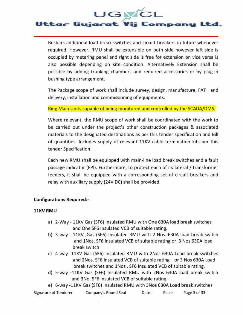
Busbars additional load break switches and circuit breakers in future whenever
required. However, RMU shall be extensible on both side however left side is
occupied by metering panel and right side is free for extension on vice versa is
also possible depending on site condition. Alternatively Extension shall be
possible by adding trunking chambers and required accessories or by plug-in
bushing type arrangement.
The Package scope of work shall include survey, design, manufacture, FAT and
delivery, installation and commissioning of equipments.
Ring Main Units capable of being monitored and controlled by the SCADA/DMS.
Where relevant, the RMU scope of work shall be coordinated with the work to
be carried out under the project’s other construction packages & associated
materials to the designated destinations as per this tender specification and Bill
of quantities. Includes supply of relevant 11KV cable termination kits per this
tender Specification.
Each new RMU shall be equipped with main-line load break switches and a fault
passage indicator (FPI). Furthermore, to protect each of its lateral / transformer
feeders, it shall be equipped with a corresponding set of circuit breakers and
relay with auxiliary supply (24V DC) shall be provided.
Configurations Required:-
11KV RMU
a) 2-Way - 11KV Gas (SF6) Insulated RMU with One 630A load break switches
and One SF6 Insulated VCB of suitable rating.
b) 3-way - 11KV ,Gas (SF6) Insulated RMU with 2 Nos. 630A load break switch
and 1Nos. SF6 insulated VCB of suitable rating or 3 Nos 630A load
break switch
c) 4-way- 11KV Gas (SF6) Insulated RMU with 2Nos 630A Load break switches
and 2Nos. SF6 Insulated VCB of suitable rating – or 3 Nos 630A Load
break switches and 1Nos , SF6 Insulated VCB of suitable rating.
d) 5-way -11KV Gas (SF6) Insulated RMU with 2Nos 630A load break switch
and 3No. SF6 insulated VCB of suitable rating -
e) 6-way -11KV Gas (SF6) Insulated RMU with 3Nos 630A Load break switches

Signature of Tenderer Company’s Round Seal Date: Place Page 4 of 33
and 3Nos , SF6 Insulated VCB of suitable rating –
PLS NOTE: THE NOMINAL CURRENT RATING OF VCB SHALL BE ACCORDING TO
LOAD OF THE FEEDER AND ACCORDINGLY SUITABLE RELAY SHALL BE
PROVIDED AND ANY CHANGE IN COMBINATION/CONFIGURATION SHALL BE
EXECUTED WITH THE APPROVAL OF CHIEF ENGINEER OF RESPECTIVE DISCOM.
a. This Specification provides for design, manufacture, inspection and testing
before dispatch, packing and delivery F.O.R.(Destination) of SF6 insulated RMUs
with necessary take off terminal units for their satisfactory operation.
b. The objective of the RMUs is for extremely small construction width, compact,
maintenance free, independent of climate, easy installation, operational
reliability, Safe and easy to operate, minimum construction cost, minimum site
work and minimum space requirement.
c. The RMUs shall conform in all respects to high standards Of Engineering design,
workmanship and latest revisions of relevant standards at the time of offer.
d. The type of the 11 KV circuit breaker shall be VCB and insulating medium for load
break isolators, Earth switch, 11 KV Buses and other associated equipments
should be SF6 gas.
� Necessary current sensors / transformers for protection and metering
(wherever required).
� All necessary dry (potential-free) contacts for indications relevant to RMU
monitoring status and control.
1.3 GENERAL:
The Ring Main Unit shall be installed at 11 KV junction points to have continuous
supply by isolating faulty sections. The RMU shall be extensible on both sides
and consists of the following combinations of load break switches and Circuit
breakers for a nominal voltage of 12 KV using SF6 gas as insulating and Vacuum
as arc quenching medium.
The RMU and combination shall be tropicalised and outdoor metal enclosed
type. The RMU metal parts shall be of high thickness, high tensile steel which

Signature of Tenderer Company’s Round Seal Date: Place Page 5 of 33
must be grit/short blasted, thermally sprayed with Zinc alloy, phosphate or
should follow the 7 tank pre-treatment process and be subsequently painted
with polyurethane/PP based powder paint. The overall paint layer thickness shall
be not less than 80 microns.
Relevant IE rules for clearances, safety and operation inside the enclosure shall
be applicable. The enclosure shall be IP 54 and type tested for weather proof at
ERDA/CPRI.
All live parts except for the cable connections in the cable compartments shall
be insulated with SF6 gas. The SF6 gas tank shall be made of robotic or TIG or
MIG welded stainless steel, to have the best weld quality. The gas cubicle shall
be metal enclosed with stainless Steel of thickness as per IEC
Tested/ designed so as to provide safety and to avoid leakage of gas and should
be provided with a pressure relief arrangement away from operator.
Both the load break switches and the tee off circuit breaker must be motorized.
The cable termination chamber of isolators and circuit breakers both should be
of front access type/Round end type as per site requirement.
Any accidental over pressure inside the sealed chamber shall be limited by the
opening of a pressure-limiting device in the top or rear-bottom part of the tank
or enclosure. Gas will be release to the rear of the switchboard away from the
operator and should be directed towards the bottom, into the trench to ensure
safety of the operating personnel and the pedestrians / civilians. All the manual
operations should be carried out on the front of the switchboard.
GENERAL TECHNICAL REQUIREMENTS
1. Fixed type SF-6 gas insulated / Vacuum circuit breakers. It should be maintenance
free, having stainless steel robotically/ TIG / MIG welded enclosure for IN DOOR
/OUTDOOR RMU. However, offer with high quality of the welding which has
necessary extensive leakage test with leak rate of 0.075% per annum can be
accepted. The RMUs to be used are only outdoor type.

Signature of Tenderer Company’s Round Seal Date: Place Page 6 of 33
2. Low gas pressure devices- 1.4 Bar pressure. 1.4 bar pressure of SF6 gas in
chamber of RMU is required.
3. Live cable indicators- High operator safety.
4. Fully rated integral earthing switch on each device.
5. Back up relay with auxiliary supply (24V DC) shall be provided.
6. For indoor Cable boxes should be front access and interlocked with earth switch.
No rear /side access required. For outdoor RMUs cable boxes shall be on front.
7. Cable testing possible without disconnection of cables.
8. Compact in dimension.
9. Circuit Breaker with back up relay with auxiliary supply (24V DC) shall be
provided.
10. Low pressure, sealed for life equipment, can operate at “0” bar pressure.
11. Cable earthing switch on all switching device-standard, for operator safety.
12. Enclosure with IP 54 standard protection for OUTDOOR RMUs and IP2X for
INDOOR RMUs
13. All live parts should be inside a stainless steel enclosure for out door type RMU
& minimum 2 mm thickness of stainless steel robotically/TIG/MIG welded
enclosure for Outdoor / indoor RMU.
TECHNICAL AND GUARANTEED PARTICULARS:
The bidders shall furnish all guaranteed technical particulars as called for in
Schedule “A” of this specification. Particulars which are subject to guarantee shall
be clearly marked. Bids lacking information in G.T.P are liable to be rejected
The Entire units or minimum three functions of RMU shall be enclosed in a single
compact metal clad, outdoor enclosure suitable for all weather conditions. The
switchgear/steel gas tank shall be filled with SF6 as per IEC/IS Standards relative
pressure to ensure the insulation and breaking functions. The steel gas tank must be

Signature of Tenderer Company’s Round Seal Date: Place Page 7 of 33
sealed for life and shall meet the “sealed pressure system” criteria in accordance
with the IEC 298 standard. The RMU must be a system for which no handling of gas
is required throughout the 25 years of service life.
The RMU shall have a design such that in the event of an internal arc fault, the
operator shall be safe. This should be in accordance with IEC 298 and relevant Test
certificates shall be submitted with the Tender.
The offered switchgear and control gear should be suitable for continuous
operation under the basic service conditions indicated below. Installation should be
in normal indoor conditions in accordance with IEC 60694.
Ambient temperature – 10 degree C to + 50 degree C
Relative humidity - up to 95%
Altitude of installation - up to 1000m, IEC 60120
1.3.1 The RMU shall be tested for an internal arc rating of 20 kA for 1 Sec. for 11 KV RMU.
Suitable temperature rise test on the RMU shall be carried out & test reports shall
be submitted with tender for technical bid evaluation.
Each switchboard shall be identified by an appropriately sized label, which clearly
indicates the functional units and their electrical characteristics.
The switchgear and switchboard shall be designed so that the position of the
different devices is visible to the operator on the front of the switchboard and
operations are visible as well.
The entire system shall be totally encapsulated. There shall be no access to exposed
conductors. In accordance with the standards in effect, the switchboards shall be
designed so as to prevent access to all live parts during operation without the use of
tools.
The entire 11 KV RMU are insulated by inert gas (SF6) suitable for operating voltage
up to 12 KV respectively. The 11 KV circuit breakers must be VCB breaker. It is
necessary to fit an absorption material in the tank to absorb the moisture from the
SF6 gas. The SF6 insulating medium shall be constantly monitored via a temperature

Signature of Tenderer Company’s Round Seal Date: Place Page 8 of 33
compensating gas pressure indicator offering a indication at different temperature
ranges, having distinctive RED and GREEN zones for safe operation.
All the RMUs must be routine tested for the following at factory in India:-
� Micro-ohm test (Contact Resistance test) for the assembly inside the tank.
� Circuit breaker analyzer test so as to ensure the simultaneous closing of all poles
for VCB.
� SF6 gas leak test.
� Partial Discharge test on the complete gas tank so as to be assure of the proper
insulation level and high product life.
� High voltages withstand.
� Secondary test to ensure the proper functioning of the live line indicators, fault
passage indicators and relays.
� As per IEC/IS standards Mechanical operation of RMU switch Must be carried
out.
1.3.2 Sulphur Hex fluoride Gas(SF6 GAS)
The SF6 gas shall comply with IEC 376,376A, and 376B and shall be suitable in all
respects for use in 11 KV RMUs under the operating conditions. The SF6 shall be
tested for purity, dew point air hydrolysable fluorides and water content as per IEC
376,376A and 376B and test certificate shall be furnished to the owner indicating
all the tests as per IEC 376 for each Lot of SF6 Gas.
DIELECTRIC MEDIUM
SF6 gas/ VCB shall be used for the dielectric medium for 11KV RMUS in accordance
with IEC376. It is preferable to fit an absorption material in the tank to absorb the
moisture from the SF6 gas/ VCB and to regenerate the SF6 gas/ VCB following arc
interruption. The SF6 gas / VCB insulating medium shall be constantly monitored
via a temperature compensating gas pressure indicator offering a simple go, no-go
indication.

Signature of Tenderer Company’s Round Seal Date: Place Page 9 of 33
General structural and mechanical construction:
The offered RMU should be of the fully arc proof metal enclosed, free standing,
floor mounting, flush fronted type, consisting of modules assembled into one or
more units. Each unit is made of a cubicle sealed-for life with SF6 gas / VCB and
contains all high voltage components sealed off from the environment.
The overall design of the indoor switchgear should be such that front access only is
required. It should be possible to erect the switchboard against a substation wall,
with HV and LV cables being terminated and accessible from the front.
The units should be constructed from Minimum 2 mm thick stainless steel sheets.
However, Offer with type test report of pressure withstand test for gas filled
compartment with pressure relief device test as per cl. no. 6-103-1 of IEC 62271-
200-2003 can be accepted for 2mm stainless steel tank thickness. The design of the
units should be such that no permanent or harmful distortion occurs either when
being lifted by eyebolts or when moved into position by rollers.
For outdoor RMUs a weather proofing process shall be carried out. SHEET METAL
MUST BE GRIT BLASED / THERMALLY SPRAYED AND POLYURETHANE PAINTED
WITH ABOUT 80 MICRON THICKNESSES, TO ACHIVE OUTDOOR WORTHINESS
AND CORROSION PROOF NESS.
- RMU ENCLOSURE MUST BE SHIELDED AGAINST SOLAR IRRADIATION AND
TESTED FOR A
AMBIENT OF 50 DEGREE C WITHOUT DERATING OF THE EQUIPMENT.
The cubicle shall have a pressure relief device. In the rare case of an internal arc,
the high pressure caused by the arc will release it, and the hot gases is allowed to
be exhausted out at the bottom / top / rear of the cubicle. A controlled direction of
flow of the hot gas should be achieved.
The switchgear should have the minimum degree of protection (in accordance with
IEC 60529)
- IP 67 for the tank with high voltage components
- IP 2X for the front covers of the mechanism

Signature of Tenderer Company’s Round Seal Date: Place Page 10 of 33
- IP 3X for the cable connection covers
- IP 54 for the outdoor enclosure.
1.4 STANDARDS:
Unless otherwise specified elsewhere in this Specification, the RMU, Switchboard
(Switchgear), Load break isolators, Instrument Transformers and other associated
accessories shall conform to the latest revisions and amendments thereof to the
following standards.
1. IEC 60 298/IEC 62 271-200/IS 12729:1988 - General requirement for Metal
Enclosed Switchgear
2. IEC60129/IEC62271-103/ IEC62271-102/IS 9921 - Alternating current
disconnector(Load break isolators) and earthing switch
3. IEC 62 271-100 & 200/IEC 60 056/IS 13118:1991 - Specification for alternating
current circuit breaker
4. IEC 62 271-1/IEC 60694 - Panel design, SF6/Vacuum Circuit Breakers
5. IEC 60044-1/IEC 60185/IS 2705:1992 - Current Transformer
6. IEC 60265-1/IS 9920:1988- High voltage switches.
7. IEC 376 - Filling of SF6 gas in RMU.
8. IEC 60273/IS: 2099 - Dimension of Indoor & Outdoor post insulators i. with
voltage > 1000 Volts.
9. IEC 60529/IS 13947(Part-1) - Degree of protection provided by
i. enclosures for low voltage switchgear and
ii. Control gear.
10. Indian Safety Regulations 2010/Relevant IS
Equipment meeting with the requirements of any other authoritative
standards, which ensures equal or better quality than the standard mentioned
above as well as latest standard shall also be acceptable. If the equipments,
offered by the Bidder conform to other standards, salient points of difference
between the standards adopted and the specific standards shall be clearly
brought out in relevant schedule. In case of any difference between provisions
of these standards and provisions of this specification, the provisions
contained in this specification shall prevail. One copy of such standards with
authentic English Translations shall be furnished along with the offer.(Hard
copy)
Applicable Standards

Signature of Tenderer Company’s Round Seal Date: Place Page 11 of 33
� The RMUs shall be manufactured to the highest quality consistent with best
practice and workmanship and in full accord with the Supplier’s quality
assurance plan. The RMUs shall conform to the Indian or IEC international
standards that are applicable. These include the standards listed in Table 1
below.
Table 1: Applicable Standards
Standard Description
IS 3427 AC metal enclosed switchgear and control gear for rated
voltages above 1 kV and up to and including 52 kV
IS 12063 Classification of degrees of protection provided by enclosures
of electrical equipment
IS 9920
(Parts 1 to 4) High Voltage Switches
IS 9921
(Parts 1 to 5)
Specification for AC disconnectors and earthing switches for
voltages above 1000 V
IS 13118 HV AC Circuit Breakers
IS 10601 Dimensions of terminals of HV Switchgear and Control gear
IS 12729 General requirements of switchgear and control gear for
voltages exceeding 1000 V
IEC 1330 High voltage/Low voltage prefabricated substations
IEC 60694 Common clauses for MV switchgear standards
IEC 6081 Monitoring and control
IS 2705 Current Transformers
IS 3156 Voltage transformers
IS 8686 Specification for Static Protective Relays
IEC 62271-
200 Standards for high voltage metal clad switchgear up to 52 KV.
INDIAN
ELECTRCIATY
REGULATION
2010
This is to be as per Central Electricity Authority (Safety
Requirement for Construction, Operation & Maintenance of
Electrical Plants and Electric Lines) Regulations, 2010
1.5 THE STANDARDS MENTIONED ABOVE ARE AVAILABLE FROM:
IEC - (INTERNATIONAL ELECTRO-TECHNICAL COMMISSION, BUREAU CENTRAL DE
LA COMMISSION, ELECTRO TECHNIQUE INTERNATIONAL, 1, RUE DE VEREMBE,
GENEVA, SWITZERLAND.)
Signature of Tenderer Company’s Round Seal Date: Place Page 12 of 33
ISO - INTERNATIONAL STANDARD ORGANISATION
1.6 SPECIFIC REQUIREMENTS IN RMU:-
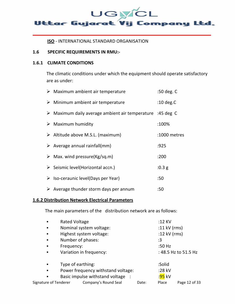
1.6.1 CLIMATE CONDITIONS
The climatic conditions under which the equipment should operate satisfactory
are as under:
� Maximum ambient air temperature :50 deg. C
� Minimum ambient air temperature :10 deg.C
� Maximum daily average ambient air temperature :45 deg C
� Maximum humidity :100%
� Altitude above M.S.L. (maximum) :1000 metres
� Average annual rainfall(mm) :925
� Max. wind pressure(Kg/sq.m) :200
� Seismic level(Horizontal accn.) :0.3 g
� Iso-ceraunic level(Days per Year) :50
� Average thunder storm days per annum :50
1.6.2 Distribution Network Electrical Parameters
The main parameters of the distribution network are as follows:
� Rated Voltage :12 KV
� Nominal system voltage: :11 kV (rms)
� Highest system voltage: :12 kV (rms)
� Number of phases: :3
� Frequency: :50 Hz
� Variation in frequency: : 48.5 Hz to 51.5 Hz
� Type of earthing: :Solid
� Power frequency withstand voltage: :28 kV
� Basic impulse withstand voltage : :95 kV

Signature of Tenderer Company’s Round Seal Date: Place Page 13 of 33
1.7 RMU OUTDOOR METAL CLAD ENCLOSURE.
The RMU enclosure must be a metallic; it shall follow an industrialized process of
manufacturing. The RMU and combination shall be tropicalised and outdoor
metal enclosed type. The RMU metal parts shall be of high thickness, high tensile
steel which must be grit/short blasted, thermally sprayed with Zinc alloy,
phosphate or should follow the 7 tank pre-treatment process and be
subsequently painted with polyurethane based powder paint. The overall paint
layer thickness shall be not less than 80 microns.
The rating of enclosure shall be suitable for operation on three phase, three wire,
11 KV, 50 cycles, A.C. System with short-time current rating of 20KA for 3 seconds
for 11 KV with RMU Panels.
The enclosure should have two access doors one for the operation and relay
monitoring and other for the cable access. Both the doors should have the
locking facility to prevent the access to operating mechanism to avoid
unauthorized operating of RMU and relay.
RMU Design Features
All design features of the proposed RMU, as described in the supplier’s bid and in
the bid’s reference materials, shall be fully supported by the equipment actually
delivered. The key design features include those that relate to:
� Maintainability, expandability, and life span
� Ability to operate in severe outdoor environmental conditions.
� Immunity to electrical stress and disturbance.
� Acceptable insulation properties.
INDOOR RMU
1. MODULAR DESIGN, PANEL TYPE WITH FRONT CABLE ACCESS.
2. RMU MUST BE MADE OF ROBOTICALLY / TIG / MIG WELDED STAINLESS
STEEL.
3. Offered RMU must be extensible.

Signature of Tenderer Company’s Round Seal Date: Place Page 14 of 33
OUT DOOR RMU
1. Stainless steel enclosure for OUT DOOR RMU application. The manufacturers
shall conform the normal current ratings mentioned in GTP at 50 deg.
Ambient without derating or as per IEC Standard
2. Enclosure with I.P.54 standard protection.
3. Offered RMU must be extensible.
4. Cable boxes shall be on Front sides.
5. RMU ENCLOSURE MUST BE SHIELDED AGAINST SOLAR IRRADIATION AND
TESTED FOR AMBIENT OF 50 DEGREE C. The manufacturers shall conform the
normal current ratings mentioned in GTP at 50 deg. Ambient without
derating, however, design for higher ambient temperature than 50 degree
may be admissible.
1.8 ISOLATORS (LOAD BREAK TYPE)
The load break isolators for Incoming and Outgoing supply must be provided.
These should be fully insulated by SF6 gas. The load break isolators shall consist
of 630 Amp fault making/load breaking spring assisted ring switches, each with
integral fault making earth switches. The switch shall be naturally interlocked to
prevent the main and earth switch being switched “ON‟ at the same time. The
selection of the main and earth switch is made by a lever on the facia, which is
allowed to move only if the main or earth switch is in the off position. The load
break isolators should have the facility for remote operation. Each load break
switch shall be of the triple pole, simultaneously operated, automatic type with
quick break contacts and with integral earthing arrangement.
The isolating distance between the OFF and the ON position in the isolator should
be sufficient to withstand dielectric test as per IS/IEC, so as to have enough
isolating distance for ensuring safety during DC injection for Cable testing.
Load break switch should have the following
� Motor operated 12 KV, 630A Load Break switch and manually operated
Earthing Switch with making capacity.
� “Live Cable” LED Indicators thru Capacitor Voltage Dividers mounted on the
bushings.

Signature of Tenderer Company’s Round Seal Date: Place Page 15 of 33
� Mechanical ON/OFF/EARTH Indication and interlocking between earth and
on/off conditions.
� Anti-reflex operating handle
� Cable Testing facility without disconnecting the cable terminations, cable joints
and terminal protectors on the bushings.
Cable terminations
� Cable boxes suitable for 1 X 3C x 300 sq mm XLPE Cable with right angle Cable
Termination Protectors.
1.9 EARTHING OF ISOLATORS AND BREAKERS (EARTH SWITCH):
Necessary arrangements are provided at Load break isolators Breaker for
selecting Earth position. Mechanical interlocking systems shall prevent the RMU
function from being operated from the “ON” to “Earth On” position without
going through the “OFF” position.
1.10 DISTRIBUTION TRANSFORMER/FEEDER BREAKER (VACUUM):
The VCB breaker for the controlling of DT/Feeder Breaker must be provided
inside welded stainless steel SF6 gas tank with the outdoor metal clad enclosure.
The VCB circuit breaker must be a spring assisted three positions with integral
fault making earth switch. The selection of the main/earth switch lever on the
facia, which is allowed to move only if the main or earth switches is in the off
position.
The manual operation of the circuit breaker shall not have an effect on the trip
spring. This should only be discharged under a fault (electrical) trip; the following
manual reset operation should recharge the trip spring and reset the circuit
breaker mechanism in the main off position.
The circuit breaker shall be fitted with a mechanical flag, which shall operate in
the event of a fault (electrical) trip occurring. The “tripped” flag should be an
unambiguous colour differing from any other flag or mimic.
Both the circuit breaker and ring switches are operated by the same
unidirectional handle.
Signature of Tenderer Company’s Round Seal Date: Place Page 16 of 33
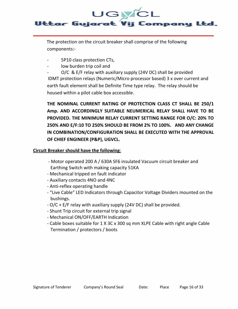
The protection on the circuit breaker shall comprise of the following
components:-
- 5P10 class protection CTs,
- low burden trip coil and
- O/C & E/F relay with auxiliary supply (24V DC) shall be provided
IDMT protection relays (Numeric/Micro processor based) 3 x over current and
earth fault element shall be Definite Time type relay. The relay should be
housed within a pilot cable box accessible.
THE NOMINAL CURRENT RATING OF PROTECTION CLASS CT SHALL BE 250/1
Amp. AND ACCORDINGLY SUITABLE NEUMERICAL RELAY SHALL HAVE TO BE
PROVIDED. THE MINIMUM RELAY CURRENT SETTING RANGE FOR O/C: 20% TO
250% AND E/F:10 TO 250% SHOULD BE FROM 2% TO 100%. AND ANY CHANGE
IN COMBINATION/CONFIGURATION SHALL BE EXECUTED WITH THE APPROVAL
OF CHIEF ENGINEER (P&P), UGVCL.
Circuit Breaker should have the following:
- Motor operated 200 A / 630A SF6 insulated Vacuum circuit breaker and
Earthing Switch with making capacity 51KA
- Mechanical tripped on fault indicator
- Auxiliary contacts 4NO and 4NC
- Anti-reflex operating handle
- “Live Cable” LED Indicators through Capacitor Voltage Dividers mounted on the
bushings.
- O/C + E/F relay with auxiliary supply (24V DC) shall be provided.
- Shunt Trip circuit for external trip signal
- Mechanical ON/OFF/EARTH Indication
- Cable boxes suitable for 1 X 3C x 300 sq mm XLPE Cable with right angle Cable
Termination / protectors / boots

Signature of Tenderer Company’s Round Seal Date: Place Page 17 of 33
TECHNICAL DATA
1 . Ring Main Unit, Electrical data :
Electrical data and service conditions
Rated voltage KV 12
1 Power frequency withstand voltage KV 28
2 Impulse withstand voltage KVp 95
3 Rated frequency Hz 50
4 Rated current busbars A 630
5 Rated current (cable switch) A 630
6 Rated current (T-off) A 630
Breaking capacities:
7 active load A 630
8 closed loop (cable switch) A 630
9 off load cable charging (cable switch) A 135
10 earth fault (cable switch) A 200
11 earth fault cable charging (cable
switch)
115
12 short circuit breaking current (T-off
circuit breaker)
kA 20 / 21
13 Rated making capacity kA 52
14 Rated short time current 3 sec. kA 20 / 21
Ambient temperature:
15 Maximum value °C + 50

Signature of Tenderer Company’s Round Seal Date: Place Page 18 of 33
16 Maximum value of 24 hour mean °C + 40
17 Minimum value °C 0
18 Altitude for erection above sea level4 m ...1000
19 Relative humidity Max 95%
2. Ring Main Unit Technical data (11KV):
No. General data, enclosure and
dimensions
1 Standard to which Switchgear
complies IEC
2 Type of Ring Main Unit Metal Enclosed, Panel type,
Compact Module.
3 Number of phases 3
4 Whether RMU is type tested Yes
5 Whether facility is provided with
pressure relief Yes
6 Insulating gas SF6
7 Nominal operating gas pressure
1.4 bar @ 20° C. However offer
with Nominal operating gas
pressure shall be as per
manufacturer standard and
suitable to satisfy the rated
dielectric strength can be
accepted
8 Gas leakage rate / annum 0.075%
9 Expected operating lifetime 30 years
10 Whether facilities are provided for
gas monitoring
Yes, temperature compensated
manometer can be delivered
11 Material used in tank construction Stainless steel sheet, minimum 2
mm

Signature of Tenderer Company’s Round Seal Date: Place Page 19 of 33
No. Operations, degree of protection
and colours
1 Means of switch operation separate handle
2 Means circuit breaker operation separate handle and push buttons
3 Rated operating sequence of Circuit
Breaker O - 3min-CO-3min-CO
4 Total opening time of Circuit Breaker approx. 45ms
5 Closing time of Circuit Breaker approx. 40ms
6 Mechanical operations of switch (co) 1000
7 Mechanical operations of CO
earthing switch 1000
8 Mechanical operations of circuit
breaker (co) 2000
9 Principle switch / earth switch 3 position combined switch /
earth switch
Degree of protection:
10 High Voltage live parts, SF6 / VCB
tank IP 67
11 Front cover mechanism IP 2X
12 Cable covers IP 3X
13 Outdoor Enclosure IP 54
Colours:
14 Front cover
15 Side and cable cover
1.11 BUSHINGS
The units are fitted with the standardized bushings that comply with IEC standards.
All the bushings are the same height from the ground and are protected by a cable
cover.
1.12 CABLE BOXES
All the cable boxes shall be air insulated suitable for dry type cable terminations
and should have front access. The cable boxes at each of the two ring switches
should be suitable for accepting HV cables of sizes 3c x 300 sq.mm and circuit
breaker cable suitable up to 3c x 300 sq.mm. The cable boxes for an isolator in its
standard design should have sufficient space for connecting two cables per phase
.Necessary Right angle Boot should be supplied to the cable terminations .The type

Signature of Tenderer Company’s Round Seal Date: Place Page 20 of 33
of the Right angle Boot should be cold applied insulating Boot. In cable box bushing
fitting required 3 KN capacities.
1.13 CABLE TESTING FACILITY
It shall be possible to test the cable after opening the cable boxes. The cable boxes
should open only after operation of the earth switch. Thus ensuring the earthing of
the cables prior to performing the cable testing with DC injection.
1.14 VOLTAGE INDICATOR LAMPS AND PHASE COMPARATORS
The RMU shall be equipped with a phase wise voltage indication to indicate
whether or not there is voltage on the each phase of cable. There should be a
facility to check the synchronization of phases with the use of external device. It
shall be possible for the each of the function of the RMU to be equipped with a
permanent voltage indication as per IEC 601958 to indicate whether or not there is
voltage on the each phase cables. Indicator should be visible from outside without
opening door.
1.15 EXTENSIBLE
Each combination of RMU shall have the provision for extension both sides by load
break isolators / breakers in future, with suitable accessories and necessary Bus
Bar. The equipment shall be well designed to provide any kind of extension /
trunking chamber for connecting and housing extensible Busbars. Extensible
isolators and circuit breakers shall be individually housed in separate SF6 gas
enclosures. Multiple devices inside single gas tank / enclosure will not be
acceptable. In case of extensible circuit breakers, the Breaker should be capable of
necessary short circuit operations as per IEC at 20 KA, and the Breaker should have
a rated current carrying capacity of 630 A.
1.16 WIRING & TERMINALS:
The wiring should be of high standard and should be able to withstand the tropical
weather conditions. All the wiring and terminals (including take off terminals for
future automation, DC, Control wiring), 20% Spare terminals shall be provided by
the contractor. The wiring cable must be standard single-core non-sheathed, Core
marking (ferrules), stripped with non-notching tools and fitted with end sleeves,
marked in accordance with the circuit diagram with printed adhesive marking
strips.

Signature of Tenderer Company’s Round Seal Date: Place Page 21 of 33
The wiring should be of high standard and should be able to withstand the tropical
weather conditions. All wiring shall be provided with single core multi-strand
flexible copper conductor wires with P.V.C insulation.
The wiring shall be carried out using multi-strand copper conductor super flexible
PVC insulated wires of 1100V Grade for AC Power, DC Control and CT circuits.
Suitable colored wires shall be used for phase identification and interlocking type
ferrules shall be provided at both ends of the wires for wire identification. Terminal
should be suitably protected to eliminate sulphating. Connections and terminal
should be able to withstand vibrations. The terminal blocks should be stud type for
controls and disconnecting link type terminals for CT leads with suitable spring
washer and lock nuts.
Flexible wires shall be used for wiring of devices on moving parts such as swinging
Panels (Switch Gear) or panel doors. Panel wiring shall be securely supported,
neatly arranged readily accessible and connected to equipment terminals, terminal
blocks and wiring gutters. The cables shall be uniformly bunched and tied by means
of PVC belts and carried in a PVC carrying trough.
The position of PVC carrying trough and wires should not give any hindrance for
fixing or removing relay casing, switches etc., Wire termination shall be made with
solder less crimping type of tinned copper lugs. Core identification plastic ferrules
marked to correspond with panel wiring diagram shall be fitted with both ends of
each wire. Ferrules shall fit tightly on the wire when disconnected. The wire
number shown on the wiring shall be in accordance with the IS.375.
All wires directly connected to trip circuits of breaker or devices shall be
distinguished by addition of a red color unlettered ferrule.
Inter-connections to adjacent Panels (Switch Gear) shall be brought out to a
separate set of Terminal blocks located near the slots or holes to be provided at
the top portion of the panel. Arrangements shall be made for easy connections to
adjacent Panels (Switch Gear) at site and wires for this purpose shall be provided
and bunched inside the panel. The bus wire shall run at the top of the panel.
Terminal block with isolating links should be provided for bus wire. At least 20% of
total terminals shall be provided as spare for further connections. Wiring shall be
done for all the contacts available in the relay and other equipment and brought
out to the terminal blocks for spare contacts. Color code for wiring is preferable in
the following colours.
� Voltage circuits : Red, Yellow, Blue for phase and Black for Neutral

Signature of Tenderer Company’s Round Seal Date: Place Page 22 of 33
� CT circuits : similar to the above
� DC circuits : Grey for both positive and negative
� 250V AC circuits : Black for both phase and neutral
� Earthing : Green
The wiring shall be in accordance to the wiring diagram for proper functioning of
the connected equipment. Terminal blocks shall not be less than 1100V grade and
shall be piece-molded type with insulation barriers.
The terminal shall hold the wires in the tight position by bolts and nuts with lock
washers. The terminal blocks shall be arranged in vertical formation at an inclined
angle with sufficient space between terminal blocks for easy wiring.
The terminals are to be marked with the terminal number in accordance with the
circuit diagram and terminal diagram. The terminals should not have any function
designation and are of the tension spring and plug-in type.
1.17 EARTHING
The RMU outdoor metal clad, Switch Gear, Load break isolators, Vacuum circuit
breakers shall be equipped with an earth bus securely fixed along the base of the
RMU.
The size of the earth bus shall be made of IEC/IS standards with tinned copper flat
for RMU and M.S.Flat for Distribution Transformer, earth spike and neutral
earthing. Necessary terminal clamps and connectors shall be included in the scope
of supply.
All metal parts of the switchgear which do not belong to main circuit and which can
collect electric charges causing dangerous effect shall be connected to the earthing
conductor made of copper having CS area of minimum 75 sq.mm. Each end of
conductor shall be terminated by M 10/equivalent quality and type of terminal for
connection to earth system installation. Earth conductor location shall not obstruct
access to cable terminations.
The following items are to be connected to the main earth conductor by rigid or
copper conductors having a minimum cross section of 75 mm (a) earthing switches
(b) Cable sheath or screen (c) capacitors used in voltage control devices, if any.
The metallic cases of the relays, instruments and other panel mounted Equipments
shall be connected to the earth bus by independent copper wires of size shall be

Signature of Tenderer Company’s Round Seal Date: Place Page 23 of 33
made of IEC/IS standards. The colour code of earthing wire shall be green. Earthing
wires shall be connected on the terminals with suitable clamp connectors and
soldering shall not be permitted.
Two no. of earthing with connecting G.I Strip (size=35mm*3mm) are to be
provided as per attached Drawing(Appendix-2) with ref IS:3043-1987(2006).
1.18 ACCESSORIES & SPARES:
The following spares and accessories shall be supplied along with the main
equipments at free of costs. This shall not be included in the price schedule.
1. Charging lever for operating load break isolators & circuit breaker of each RMU.
2. The pressure gauges indications - 1 numbers
Provision shall be made for padlocking the load break switches/ Circuit breaker,
and the earthing switches in either open or closed position with lock & master key.
1.19 TESTING OF EQUIPMENT & ACCESSORIES:
Provision for testing CTs, PTs, Relays, Breakers and Cables shall be made available.
Procedure and schedule for Periodical & Annual tastings of equipments, relays, etc.
shall be provided by the supplier.
1.19.1 TYPE TEST
The Tenderers should, along with the tender documents, submit copies of all Type
test certificate of their make including breaker and Isolators in full shape as
confirming to relevant ISS/IEC of latest issue obtained from a
International/National Govt. Lab/Recognized laboratory.
The above type test certificates should accompany the drawings for the materials
duly signed by the institution who has type test certificate.
1.19.2 ACCEPTANCE AND ROUTINE TESTS
All acceptance and routine tests as stipulated in the latest IEC- shall be carried out
by the supplier in the presence of DISCOM’s representative. The supplier shall give
at least 15 days advance intimation to the DISCOM to enable them to depute their
representative for witnessing the tests. The partial discharge shall be carried out as
routine test on each and every completely assembled RMU gas tank and not on a
sample basis. As this test checks and guarantees for the high insulation level and
thus the complete life of switchgear.

Signature of Tenderer Company’s Round Seal Date: Place Page 24 of 33
1.19.3 ADDITIONAL TESTS
The DISCOM reserves the right for carrying out any other tests of a reasonable
nature at the works of the supplier/laboratory or at any other recognized
laboratory/research institute in addition to the above mentioned type, acceptance
and routine tests at the cost of the Board to satisfy that the material complies with
the intent of this specification.
1.19.4 PRE-COMMISSIONING TESTS
All the pre-commissioning tests will be carried out in the presence of the DISCOM’s
testing engineer and necessary drawing manual and periodical test tools shall be
arranged to be supplied.
During the above tests the contractor representative should be present till the
RMUs are put in to service.
1.20 INSPECTION:
The inspection may be carried out by the DISCOM at any stage of manufacture. The
supplier shall grant free access to DISCOM’s representative at a reasonable time
when the work is in progress. Inspection and acceptance of any equipment under
this specification by the DISCOM shall not relieve the supplier of his obligation of
furnishing equipment in accordance with the specification and shall not prevent
subsequent rejection if the equipment is found to be defective.
The supplier shall keep the DISCOM informed in advance, about the manufacturing
programme so that arrangement can be made for inspection. The DISCOM reserves
the right to insist for witnessing the acceptance/routine testing of the bought out
items. The DISCOM has rights to inspect the supplier’s premises for each and every
consignment for type & routine test.
No material shall be dispatched from its point of manufacture unless the material
has been satisfactorily inspected and tested / unless the same is waived by the
DISCOM in writing.
1.21 QUALITY ASSURANCE PLAN:
The bidder shall invariably furnish following information along with his offer / in
case of event of order.
I. Statement giving list of important raw materials including but not limited to
a) Contact material

Signature of Tenderer Company’s Round Seal Date: Place Page 25 of 33
b) Insulation
c) Sealing material
d) Contactor, limit switches, etc. in control cabinet.
Name of sub-suppliers for the raw materials, list of standards according to which
the raw materials are tested, list of test normally carried out on raw materials in
presence of Bidder’s representative, copies of test certificates.
II. Information and copies of test certificates as in (I) above in respect of bought
out accessories & raw materials.
III. List of areas in manufacturing process, where stage inspections are to be
carried out.
IV. Normally carried out for quality control and details of such tests and
inspections.
V. Special features provided in the equipment to make it maintenance free.
VI. List of testing equipment available with the Bidder for final testing of RMUs and
associated combinations vis-à-vis the type, special, acceptance and routine
tests specified in the relevant standards. These limitations shall be very clearly
brought out in the relevant schedule i.e. schedule of deviations from specified
test requirements. The supplier shall, within 15days from the date of receipt of
Purchase Order submit following information to the DISCOM.
a) List of raw materials as well bought out accessories and the names of sub-
suppliers selected from those furnished along with offer.
b) Necessary test certificates of the raw material and bought out accessories.
c) Quality Assurance Plan (QAP) with hold points for DISCOM’s inspection. The
quality assurance plan and hold points shall be discussed between the DISCOM
and supplier before the QAP is finalized.
The supplier shall submit the routine test certificates of bought out items and
raw material, at the time of routine testing of the fully assembled breaker.
1.22 TRAINING:
The supplier shall give rigorous training to the engineers & staff for 2 days in
attending trouble shooting and maintenance.

Signature of Tenderer Company’s Round Seal Date: Place Page 26 of 33
1.23 DOCUMENTATION and DRAWINGS
All drawings shall conform to relevant International Standards Organization (ISO)
Specification. All drawings shall be in ink and suitable for microfilming.
The tenderer shall submit along with his tender dimensional general arrangement
drawings of the equipments, illustrative and descriptive literature in triplicate for
various items in the RMUs which are all essentially required for future
automation.
I. Schematic diagram of the RMU panel
II. Instruction manuals
III. Catalogues of spares recommended with drawing to indicate each items
of spares
IV. List of spares and special tools recommended by the supplier.
V. Copies of Type Test Certificates as per latest IS/IEC.
VI. Drawings of equipments, relays, control wiring circuit, etc.
VII. Foundation drawings of RMU so that Utility will planned and carry out
civil works etc.
VIII. Dimensional drawings of each material used for item VII.
IX. Actual single line diagram of RMU/RMUs with or without Extra
combinations shall be made displayed on the front portion of the RMU so
as to carry out the operations easily.
The following should be supplied to each consignee circle/town along with the
initial supply of the equipments ordered.
a. Copies of printed and bound volumes of operation, maintenance and
erection manuals in English along with the copies of approved drawings and
type test reports etc.
b. Sets of the manuals as above shall be supplied to the Chief
Engineer/Distribution. A soft copy of the all Technical and Drawing furnished
in a CD

Signature of Tenderer Company’s Round Seal Date: Place Page 27 of 33
1.24 NAME PLATE:
Each RMU and its associated equipments shall be provided with a nameplate
legible and indelibly marked with at least the following information.
a. Name of manufacturer
b. Type, design and serial number
c. Rated voltage and current
d. Rated frequency
e. Rated symmetrical breaking capacity
f. Rated making capacity
g. Rated short time current and its duration
h. Purchase Order number and date
i. Month and Year of supply
j. Last date of completion of Guarantee period
k. Rated lightening impulse withstand voltage
l. Feeder name (Incoming and Outgoing), DTs Structure name, 11000 Volts
Dangers etc.
j Name of DISCOM
NOTE:
I) THE WORD RATED NEED NOT APPEAR ON THE NAME PLATE. RECOGNIZED
ABBREVIATIONS MAY BE USED TO EXPRESS THE ABOVE PARTICULARS.
II) WHETHER THE CIRCUIT BREAKER IS FITTED WITH CLOSING/TRIPPING DEVICES
NECESSITATING AN AUXILIARY SUPPLY SHALL BE STATED EITHER ON THE CIRCUIT
BREAKER NAME PLATE OR ANY OTHER ACCEPTABLE POSITION.
1.25 FAULT PASSAGE INDICATORS (FPI):
These shall facilitate quick detection of faulty section of line. The fault
indication may be on the basis of monitoring fault current flow through the device.
The unit should be self-contained requiring no auxiliary power supply. The FPI shall
be integral part of RMU. The FPI shall have LCD/LED display, automatic reset
facility.

Signature of Tenderer Company’s Round Seal Date: Place Page 28 of 33
The sensors to be bushing/cable mounted. The number of FPI should be put in all
the three phases of the outgoing branch of the RMUs
FPI should have suitable connectivity with the FRTUs for the SCADA purpose.
FPI has to give indication on short circuit and earth fault both.
FPI Indication should be visible from outside without opening of door.
The FPI inside the RMU may be non communicable and hard wired to the TB for
the signals
Fault Passage indicator OK
Fault Passage indicator operated
The conventional practice is to have (N-1) FPI where N is nos. of LBS in a particular
configuration of RMU i.e. following for tendered RMUs:
2WAY - 1
3WAY - 1
4WAY - 1
5WAY - 2
6WAY - 2
1.26 TROPICALISATION
Due regard should be given to the climatic conditions under which the equipment
is to work. Ambient temperatures normally vary between 20 deg C and 40 deg C,
although direct sun temperature may reach 45 deg C. The climate is humid and
rapid variations occur, relative humidity between 60% and 95% being frequently
recorded, but these values generally correspond to the lower ambient
temperatures. The equipment should also be designed to prevent ingress of
vermin, accidental contact with live parts and to minimize the ingress of dust and
dirt. The use of materials which may be liable to attack by termites and other
insects should be avoided.
1.27 TECHNICAL SPECIFICATION FOR RMU
1.27.1 11 KV Bus Bar
I. Current Carrying Capacity : 630 Amps.
II. Short time rating current for 3 secs. : 20 KA for 11kv
III. Insulation of bus bar : SF6
IV. Bus bar connections : Anti-oxide grease

Signature of Tenderer Company’s Round Seal Date: Place Page 29 of 33
1.28 PARAMETERS FOR SWITCH GEAR OF DT AND LOAD BREAK ISOLATORS
I. Type : Metal enclosed
II. No of Phases : 3
III. No. of poles : 3
IV. Rated voltage :12 KV
V. Operating voltage :11 KV(+10% to -20%)
VI. Rated lightning impulse withstand voltage :95 KV
VII. Rated power frequency withstand voltage :28 KV
VIII. Insulating gas :SF6
IX. Rated filling level for insulation :As Per IEC.
X. Max.permissible site altitude at the above gas pressures : 1000m
(The operating pressure has to be adjusted for greater altitudes)
XI. Isolating distance between ON and OFF position in isolator :80 mm (min).
XII. Rated short time current :20 KA.for 11kv
XIII. Rated short time :3s
XIIII. Rated peak withstand current :50 KA.
XV. No of operations in Short circuit :15Nos (minimum)
Operating mechanism: Circuit breaker with spring assisted anti reflex
mechanism. Rated current (Bus): :630 A
Rated current (breaker) :200 A
Circuit Breaker interrupter :SF6 insulated VCB
Rated frequency : 50 Hz
Rated operating sequence :O-3min- CO
Number of mechanical/Remote operations for earthing : As per IEC
& Ring switches & Number of mechanical/ Remote operations for circuit
breakers 60298
1.29 PRINCIPAL FEATURES
Sr.
No
DESCRIPTION Breaker
1 Circuit label Yes
2 Mimic diagram Yes
3 Supply voltage indication Yes
4 Current Transformer Yes

Signature of Tenderer Company’s Round Seal Date: Place Page 30 of 33
5 IDMT O/C & E/F Numerical/Microprocessor relay with
auxiliary supply (24V DC) shall be provided.
Yes
6 Anti - Reflexing Handle Yes
7 Interlock to defeat the operation of the line side earthing
when the line side isolator is ON.
Yes
8 Interlock to defeat the operation of the earthing when the
breaker is in service position and is ON.
Yes
9 Breaker ON/OFF indication Yes
10 Spring Charge indication / Spring assisted mechanism. Yes
11 Fault Tripping indication Yes
12 Bus bar end caps Yes
13 Whether the SF6 gas pressure gauge indicator and filling
arrangement.
Yes
14 Whether the spring assisted mechanism with operating
handle for ON/OFF.
Yes
15 Whether the earth positions with arrangement for padlocking
in each position and independent manual operation with
mechanically operated indicator are provided
Yes
1.30 Earthing switch for 11 KV Line side Isolation and DT
Rated short time current : 20 KA.for 11kv.
Rated short time :3s
Rated peak withstand current :50 KA
Interlocking facility:
1) Between 11 KV Line side isolator “ON”&Earthing.
2) Between 11 KV DT side breaker on close condition &earthing
1.31 Current Transformers for breaker
CT Type : Tape wound
CT Description : THE NOMINAL CURRENT RATING OF PROTECTION CLASS CT
SHALL BE 250/1 Amp. AND ACCORDINGLY SUITABLE NEUMERICAL RELAY SHALL
HAVE TO BE PROVIDED. THE MINIMUM RELAY CURRENT SETTING RANGE FOR
O/C: 20% TO 250% AND E/F:10 TO 250% SHOULD BE FROM 2% TO 100%.
Accuracy Class CT :0.5/5P10 Rated burden : 15 VA.
Signature of Tenderer Company’s Round Seal Date: Place Page 31 of 33
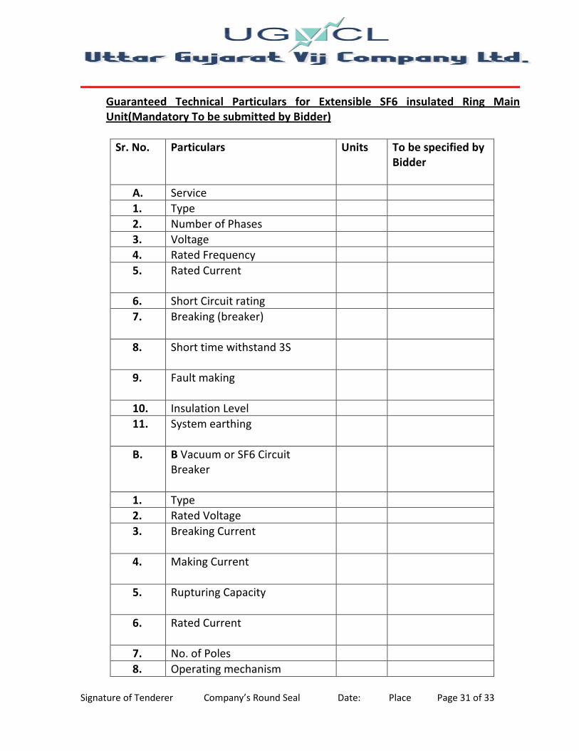
Guaranteed Technical Particulars for Extensible SF6 insulated Ring Main
Unit(Mandatory To be submitted by Bidder)
Sr. No. Particulars Units To be specified by
Bidder
A. Service
1. Type
2. Number of Phases
3. Voltage
4. Rated Frequency
5. Rated Current
6. Short Circuit rating
7. Breaking (breaker)
8. Short time withstand 3S
9. Fault making
10. Insulation Level
11. System earthing
B. B Vacuum or SF6 Circuit
Breaker
1. Type
2. Rated Voltage
3. Breaking Current
4. Making Current
5. Rupturing Capacity
6. Rated Current
7. No. of Poles
8. Operating mechanism

Signature of Tenderer Company’s Round Seal Date: Place Page 32 of 33
9. Breaker Operating Time
10. i) Break Time msec.
ii) Make Time msec.
iii) No. of Operations
a) At full load current
b) At Fault Current
C. Isolators
1. Type
2. Duty cycle
3. Rated current
4. Rated breaking capacity
5. Fault making capacity
6. Rupturing Capacity
7. No. of poles
8. Operating mechanism
9. SF6 tank
10. Interlocks
11. Operation safety
D. Busbars:
1. Material
2. Type
3. Rated Current

Signature of Tenderer Company’s Round Seal Date: Place Page 33 of 33
4. Short time rating for 3 Sec.
E. Cable Boxes
1. Air Termination
F. Current Transformer
1. C.T. Ratio
2. Over current factor
3. Class of accuracy
4. Rated Burden
G. Configuration(Left to Right
facing front of Ring Main Unit)
H. Protection
1. Three phase over current and
Earth Fault
I. Size of RMUs( L X W X D )(for
civil works etc –under Utility
scope)
1. 1 Circuit Breaker 1 Isolater
2. 1 Circuit Breaker 2 Isolater
3. 1 Circuit Breaker 3 Isolater
4. 2 Circuit Breaker 2 Isolater
5. 3 Isolator
6. 3 Circuit Breaker 2 Isolater