
System and method for collecting and refining SF6 gas
20
(19) J (12) Europaisches Patentamt ||| || 1 1| || || || || || || ||| || ||| || European Patent Office Office europeen des brevets (11) EP 0 885 841 A1 EUROPEAN PATENT APPLICATION (43) Date of publication: (51) mt. CI.6: C01B 17/45, H02B 13/055, 23.12.1998 Bulletin 1998/52 B01 D 53/68 H01 H 33/56 (21) Application number: 98111045.5 (22) Date of filing: 16.06.1998 (84) Designated Contracting States: • Tsubaki, Toru AT BE CH CY DE DK ES Fl FR GB GR IE IT LI LU Hitachi-shi, Ibaraki, 316-0011 (JP) MC NL PT SE • Nadamura, Akio Designated Extension States: Hitachinaka-shi, Ibaraki, 312-0042 (JP) AL LT LV MK RO SI • ItO, Koji Hitachinaka-shi, Ibaraki, 312-0055 (JP) (30) Priority: 20.06.1997 JP 163715/97 • Ohi, Toshio Kawasaki-shi, Kanagawa, 210-0867 (JP) (71) Applicants: . Ohno, Hiromoto • Hitachi Engineering & Services Co., Ltd. Kawasaki-shi, Kanagawa, 210-0867 (JP) Hitachi-shi, Ibaraki 317-0073 (JP) • Showa Denko Kabushiki Kaisha (74) Representative: Tokyo 105-851 8 (JP) Strehl Schubel-Hopf & Partner Maximilianstrasse 54 (72) Inventors: 80538 Munchen (DE) • Tamata, Shin Higashiibaraki-gun, Ibaraki, 311-1301 (JP) (54) System and method for collecting and refining SF6 gas (57) SF6 gas collected from the inside of a gas insu- lated machine (1) during maintenance and inspection is refined, and compositions of the refined SF6 gas are analysed and confirmed to be reused at the site. Acidic gases are neutralised and removed by a dry method using filters (4, 8, 9) and the refined SF6 gas is collected in a collecting tank (10). The composition of the col- lected SF6 gas after being refined is measured and con- firmed by an analysis equipment (1 4) to quantitatively confirm whether or not the refined SF6 gas is reusable. FIG.1 CO LO CO CO o Q_ LU .A. GAS INSULATED MACHINE ! 2 3 FIRST FILTER re EXHAUST GAS FILTER 14V ANALYSIS EQUIPMENT 4& ^7b V . BYPASS 7c THREE-WAY VALVE SECOND FILTER THIRD FILTER COOLER 15 -12 11 COLLECTING TANK ^19 X~18 HEATERf Printed byXerox (UK) Business Services 2.16.6/3.4
-
Upload
khangminh22 -
Category
Documents
-
view
6 -
download
0
Transcript of System and method for collecting and refining SF6 gas
(19) J
(12)
Europaisches Patentamt | | | | | 1 1| | | | | | | | | | | || | | | | | | | | | | European Patent Office
Office europeen des brevets (11) E P 0 8 8 5 8 4 1 A 1
EUROPEAN PATENT A P P L I C A T I O N
(43) Date of publication: (51) mt. CI.6: C01B 17/45, H02B 13/055, 23.12.1998 Bulletin 1998/52 B01 D 53/68 H01 H 3 3 / 5 6
(21) Application number: 98111045.5
(22) Date of filing: 16.06.1998
(84) Designated Contracting States: • Tsubaki, Toru AT BE CH CY DE DK ES Fl FR GB GR IE IT LI LU Hitachi-shi, Ibaraki, 316-0011 (JP) MC NL PT SE • Nadamura, Akio Designated Extension States: Hitachinaka-shi, Ibaraki, 312-0042 (JP) AL LT LV MK RO SI • ItO, Koji
Hitachinaka-shi, Ibaraki, 312-0055 (JP) (30) Priority: 20.06.1997 JP 163715/97 • Ohi, Toshio
Kawasaki-shi, Kanagawa, 210-0867 (JP) (71) Applicants: . Ohno, Hiromoto
• Hitachi Engineering & Services Co., Ltd. Kawasaki-shi, Kanagawa, 210-0867 (JP) Hitachi-shi, Ibaraki 317-0073 (JP)
• Showa Denko Kabushiki Kaisha (74) Representative: Tokyo 1 05-851 8 (JP) Strehl Schubel-Hopf & Partner
Maximilianstrasse 54 (72) Inventors: 80538 Munchen (DE)
• Tamata, Shin Higashiibaraki-gun, Ibaraki, 311-1301 (JP)
(54) System and method for collecting and refining SF6 gas
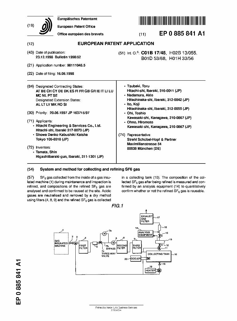
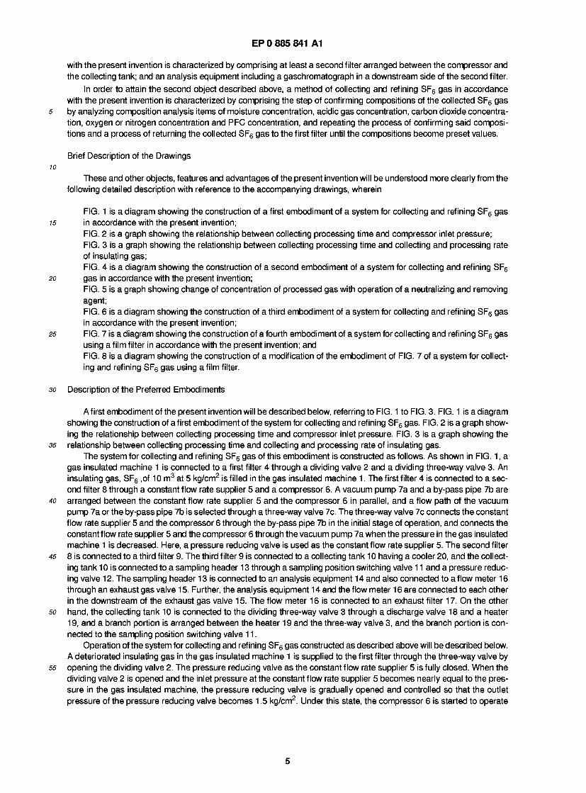
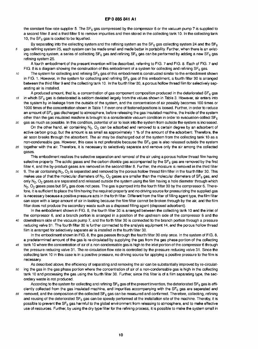
(57) SF6 gas collected from the inside of a gas insu- lated machine (1) during maintenance and inspection is refined, and compositions of the refined SF6 gas are analysed and confirmed to be reused at the site. Acidic gases are neutralised and removed by a dry method using filters (4, 8, 9) and the refined SF6 gas is collected
in a collecting tank (10). The composition of the col- lected SF6 gas after being refined is measured and con- firmed by an analysis equipment (1 4) to quantitatively confirm whether or not the refined SF6 gas is reusable.
FIG.1
CO LO CO CO o Q_ LU
.A .
GAS INSULATED MACHINE
! 2 3
FIRST FILTER r e
EXHAUST GAS FILTER
14V ANALYSIS EQUIPMENT
4 & 7̂b
V. BYPASS 7c THREE-WAY VALVE
SECOND FILTER THIRD FILTER
COOLER
15
-12 11
COLLECTING TANK
1̂9 X~18
HEATERf
Printed by Xerox (UK) Business Services 2.16.6/3.4
EP 0 885 841 A1
Description
Background of the Invention
5 The present invention relates to a system for collecting and refining SF6 gas at maintenance and inspection of an insulated machine using SF6 gas as an insulating gas and a method therefor and, more particularly, to a system for col- lecting and refining SF6 gas and a method therefor suitable for recovering a deteriorated FS6 gas by collecting and refin- ing.
Gas insulated machines commonly use SF6 gas which is an inflammable insulating gas. For example, in the past 10 transformers have employed an insulating oil as the insulating material, but an inflammable insulating gas is used
instead of the insulating oil because the insulating oil has a probability of occurrence of fire or explosion in a case of trouble. SF6 gas is widely used as the insulating gas. SF6 gas has a global Warming property (hereinafter referred to as GWP) coefficient as large as approximately 25000 and accordingly has a large effect to the global Warming. There- fore, from the viewpoint of global warming prevention, it is preferable to prevent SF6 gas, even a small quantity, from
15 discharging to atmosphere. Further, the density of SF6 gas is approximately five times as large as that of air, there is a possibility to cause an accident resulting in injury or death by an oxygen shortage when SF6 gas is discharged inside a room because it stagnates in the bottom portion of the room or the lowermost portion of the building.
Furthermore, it is known that SF6 gas is partly decomposed during using by arc discharge or the like, and part of the discomposed compositions react with moisture to produce acidic gases. Therefore, by-product refining gases are
20 produced. That is, as shown in Table 1 , SF6 gas is partly decomposed by discharge or arc to produce acidic gases and metal fluorides such as HE, SOF2, S02, H2S03, SF4, SF2, S2F2 and so on.
T a b l e 1
SF6 -> SF4, SF2, S2F2, F2, M e t a l f l u o r i d e s . When m o i s t u r e
e x i s t s , t h e f o l l o w i n g r e a c t i o n s o c c u r .
SF, + H,0 -» SOF, + 2HF
SOF2 + H20 -» S02 + 2HF
S02 + H20 -» H2S03
SQ2 + F2 -» SQ2F2
40 In addition to these, there are some reports that C02 and so on are produced from an organic component such as winding portion, and that CF4 is partially produced. As described above, although SF6 gas is a useful gas as an insu- lating gas, SF6 gas has a large global warming property coefficient and accordingly release of SF6 gas to atmosphere is harmful to the global warming, and SF6 gas may cause an accident such as an oxygen shortage when SF6 gas is discharged inside a room because the density of SF6 gas is large, and in addition to these SF6 gas is harmful because
45 it contains the acidic gases. Therefore, a method of collecting or recovering the deteriorated SF6 gas is also required from social needs.
From the above reason, at maintenance and inspection of an insulated machine using SF6 gas, a method of col- lecting and bringing back SF6 gas and refining the SF6 gas to be reused is proposed. For example, a decomposed gas treating system for a SF6 gas insulated electric machine is disclosed in Japanese Patent Application Laid-Open No.9-
50 856 proposes a method in which acidic gases among by-product gases contained in a deteriorated used SF6 gas is removed by bubbling in an alkaline solution and then the SF6 gas is filled in a compressed-gas cylinder to be brought back and refine the SF6 gas.
Further, an article entitled "1512 An SF6 gas collecting apparatus in a large electric power test site" presented at the National Meeting of the Institute of Electrical Engineers of Japan (1996) proposes a method in which SF6 gas is
55 refined to a reusable purity by (1) removing metal fluorides, (2) removing decomposed gases, (3) removing moisture and (4) removing impurities using an air removing block. This method is to remove acidic gases using an alkaline solu- tion, and proposes a system which has a dew-point meter and an oxygen concentration meter so that quantities of moisture and air content can be monitored. This process can satisfy the SF6 gas standard of "IEC-376 New Gas Stand-
2
EP 0 885 841 A1
ard" shown in Table 2.
Table 2
Moisture lower than 1 5 wt ppm Air lower than 500 wt ppm Hydrolytic fluoride (HF) lower than 1 .0 wt ppm
10 Although the social need that the deteriorated SF6 gas is collected at inspection and maintenance and refined to
be reused is increasing as described above, the technologies disclosed in Japanese Patent Application Laid-Open No.9-856 and described in the article entitled "1512 An SF6 gas collecting apparatus in a large electric power test site" presented at the National Meeting of the Institute of Electrical Engineers of Japan (1996) are still technically insufficient
15 to cope with the need. This is because the purity of the refined SF6 gas is still not sufficiently confirmed and guaranteed, and the system for collecting and refining SF6 gas is very large in size.
Initially, the confirmation and guarantee of gas purity will be described. SF6 gas is an important factor to dominate the insulation performance of a gas insulated transformer or a gas insulated switch-gear. Therefore, in order to refine and reuse the SF6 gas, it is required to confirm that the performance of the recovered SF6 gas is equivalent to that of
20 new SF6 gas. If the recovered SF6 gas contains impurities and the insulating performance is degraded, the apparatus is broken and damaged by occurrence of a short circuit inside the apparatus. Therefore, the collection and refinement requires confirmation by measuring the property of the recovered SF6 gas. Table 3 shows an analysis result of an SF6 gas used in a gas insulated switch-gear after repeating to open and close. In order to confirm that the performance of the recovered SF6 gas is equivalent to that of new SF6 gas, it is necessary to measure on the items and to confirm the
25 concentrations. In order to do so, it is necessary to measure the items using measurement apparatuses matching to respective gases.
Table 3
Example of a result of analyzing components of a deteriorated SF6 gas No. Item Contents Concentration (ppm) 1 Solids Fluorides, Sulfides and others
2 Acidic gases SF4, SF2, S2F2, SOF2, S02F2, HF and the like 5000
3 Carbon dioxide C02 1500
4 PFC CF4, C2F6, C2F4 and the like 1000
5 Air 02, N2 600
6 Moisture H20 20
Further, since the gas insulated machine can be made small in size compared to that of the conventional method, the gas insulated machine in a substation in a town is usually installed in a basement form the viewpoint of effective use
45 of the site area. In this case, since the gas insulating method has less fire potential compared to the conventional oil insulating method in addition to the advantage of small size, gas insulated machines are widely employed.
On the other hand, there are many substations of ground installed type in the suburb, the gas insulated machine capable of reducing the installation area is advantageous even in such a case.
The gas insulated machines are distributedly installed in many sites as described above, it is required that the sys- 50 tern for collecting and refining the SF6 gas to reuse it is small and portable. If the system for collecting and refining is
not small and portable, it is required to fill the collected gas into a compressed gas-cylinder and to transfer it to a place where a refining apparatus is installed and then after refining to transfer it to the site again. Therefore, time period of the inspection process is lengthened and work for carrying in and out the compressed-gas cylinder is necessary. In a case where new SF6 gas is filled after a deteriorated SF6 gas is collected, delay in time period of the inspection process can
55 be avoided, but work for carrying in and out of the compressed-gas cylinder of the collected gas and the compressed- gas cylinder of new SF6 gas is required. In addition to this, the treatment of the collected deteriorated SF6 gas is addi- tionally required. In a case of a basement substation, the amount of work for carrying in and out of the collecting and refining system and of the compressed-gas cylinders becomes large and size of the transportation port also becomes
3
EP 0 885 841 A1
a limitation. Therefore, a small sized collecting and refining system is required. Both of Japanese Patent Application Laid-Open No.9-856 and the article entitled "1512 An SF6 gas collecting
apparatus in a large electric power test site" presented at the National Meeting of the Institute of Electrical Engineers of Japan (1996) propose a wet method of refining deteriorated SF6 gas where acidic gases are removed by letting the
5 deteriorated SF6 gas through lime-water solving calcium hydroxide in saturation. However, since the solubility of cal- cium hydroxide is small (0.16 g/100 g water at 20 °C) and accordingly the amount of the solution becomes large when it is used in an aqueous solution, there are problems in that the size of the apparatus becomes large and that a large amount of waste water is produced and a lot of time and effort are required in the transportation and treatment of the waste water. Particularly, since the waste water has a potential of leakage, the waste water needs to be carefully han-
10 died and managed, and there are various kinds of problems in handling the waste water in a limited place such as a basement.
Since the conventional SF6 gas collecting system has only a gas collecting function but not a gas refining function, the conventional SF6 gas collecting system is designed based on the viewpoint of how fast SF6 gas is collected from a gas insulated machine in order to improve work efficiency. When SF6 gas is filled in a gas insulated machine, for exam-
15 pie, at a pressure of 5 kg/cm2, the SF6 gas is firstly collected into a collecting tank until pressure of the collecting tank and pressure of the gas insulated machine becomes equilibrium by opening a communicating pipe line, and then the remaining SF6 gas is collected into the collecting tank using a compressor or a vacuum pump.
In a case of employing this method, pressure of the machine side is decreased from 5 kg/cm2 to approximately 3 kg/cm2 within a 1 to 2 minutes after opening the communicating pipe line. Then, the remaining SF6 gas is collected
20 using the compressor. However, approximately 1/3 of the gas has been collected by the opening of the communicating pipe line. Since an efficiency of the compressor decreases as the pressure in the machine side is decreased, an amount of collecting gas per unit time is decreased as the compressor is operated and the amount of collecting gas per unit time becomes the minimum at the end of the collecting work.
In a case where the processing rate of gas per unit time in the refining process is varied regardless of whether the 25 process is of a wet method or a dry method, the refining process system needs to be designed so as to meet to the
maximum processing gas flow rate. In a case where concentration of acidic gases in the SF6 gas is reduced down to a predetermined value, design of the system of the wet method is performed by determining a used amount of alkaline solution to a unit volume of the treated gas (ratio of solution to gas) to a predetermined value. On the other hand, in a case of the dry method, design is also performed by determining a ratio of the treated gas volume treated in unit time
30 to a volume of an adsorption removing agent (SV value). Therefore, the system needs to be designed so as to meet to the maximum gas flow rate when the processed gas rate varies, which leads to problems in that the system becomes large in size and consequently optimization and small-sizing of the system cannot be attained. Further, when the gas flow rate exceeds a value of design condition, a large amount of the alkaline solution is carried over by the gas in a case of the wet method to cause a trouble in the following process. Furthermore, regardless of the dry method or the wet
35 method, there occurs a problem in that the initial removing performance cannot be attained.
Summary of the Invention
A first object of the present invention is to provide a system for collecting and refining SF6 gas and a method of col- 40 lecting and refining SF6 gas which are small-sized and easy-operable in collection and refinement of SF6 gas from an
SF6 gas insulated machine. A second object of the present invention is to provide a system for collecting and refining SF6 gas and a method of
collecting and refining SF6 gas which are capable of measuring and confirming compositions of SF6 gas and capable of reusing the SF6 gas in a short time at a working site of the SF6 gas collecting and refining processing.
45 In order to attain the first object described above, a system for collecting and refining SF6 gas in accordance with the present invention is characterized by comprising a first filter connected to a gas insulated machine; a constant flow rate supplier connected to a downstream side of the first filter; a compressor and a vacuum pump connected in parallel to a downstream side of the constant flow rate supplier; a collecting tank connected to a downstream side of the com- pressor; and a cooler for cooling the collecting tank, wherein the first filter is constructed by a filter filled with a dry
so adsorbent. In addition to this, the system for collecting and refining SF6 gas is characterized by further comprising a constant
flow rate valve arranged in an inlet side of said compressor. In order to attain the first object described above, a method of collecting and refining SF6 gas in accordance with
the present invention is characterized by comprising the steps of removing impurities from SF6 gas from a gas insulated 55 machine by averaging a flow rate of the SF6 gas and letting the SF6 gas flow through a first filter filled with a dry adsorb-
ent; adsorbing and removing by-product gases by a second filter filled with a dry adsorbent; and collecting the SF6 gas separated by the second filter by cooling and liquefying the SF6 gas.
In order to attain the second object described above, a system for collecting and refining SF6 gas in accordance
4
EP 0 885 841 A1
with the present invention is characterized by comprising at least a second filter arranged between the compressor and the collecting tank; and an analysis equipment including a gaschromatograph in a downstream side of the second filter.
In order to attain the second object described above, a method of collecting and refining SF6 gas in accordance with the present invention is characterized by comprising the step of confirming compositions of the collected SF6 gas
5 by analyzing composition analysis items of moisture concentration, acidic gas concentration, carbon dioxide concentra- tion, oxygen or nitrogen concentration and PFC concentration, and repeating the process of confirming said composi- tions and a process of returning the collected SF6 gas to the first filter until the compositions become preset values.
Brief Description of the Drawings 10
These and other objects, features and advantages of the present invention will be understood more clearly from the following detailed description with reference to the accompanying drawings, wherein
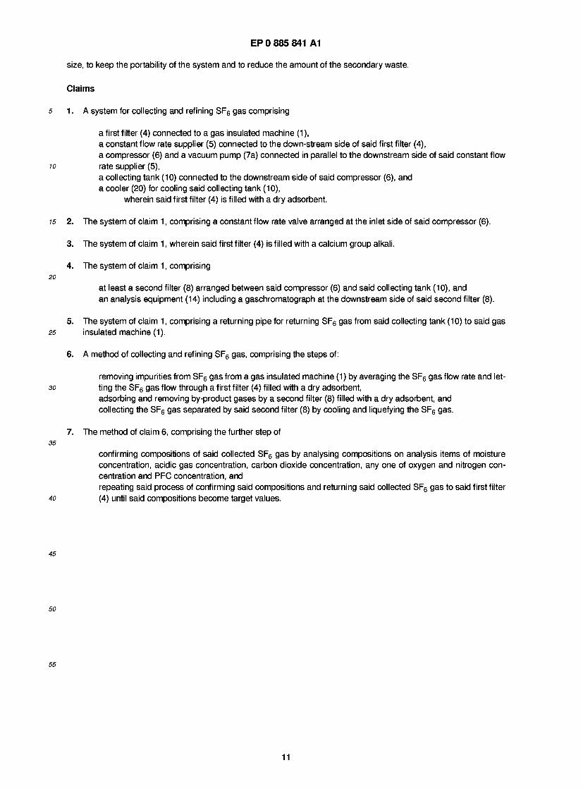
FIG. 1 is a diagram showing the construction of a first embodiment of a system for collecting and refining SF6 gas 15 in accordance with the present invention;
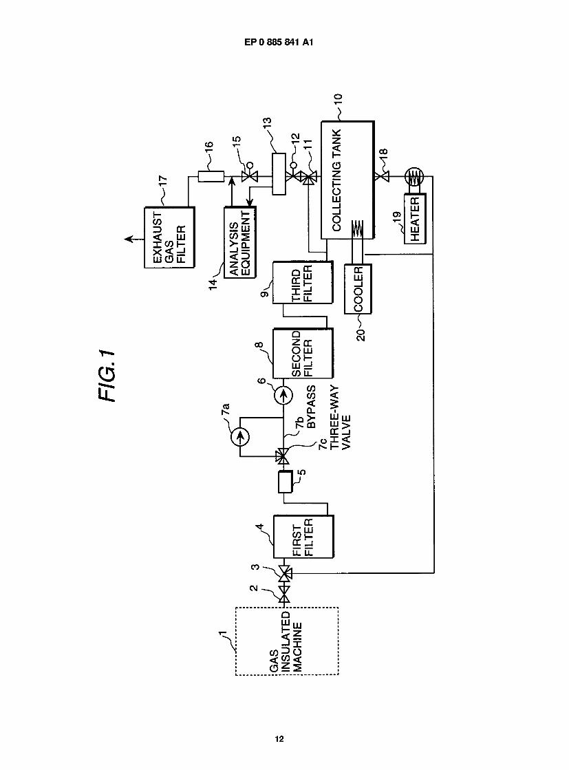
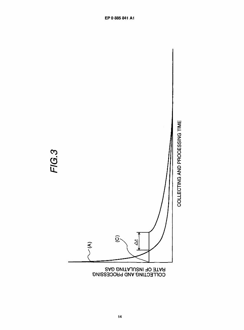
FIG. 2 is a graph showing the relationship between collecting processing time and compressor inlet pressure; FIG. 3 is a graph showing the relationship between collecting processing time and collecting and processing rate of insulating gas; FIG. 4 is a diagram showing the construction of a second embodiment of a system for collecting and refining SF6
20 gas in accordance with the present invention; FIG. 5 is a graph showing change of concentration of processed gas with operation of a neutralizing and removing agent; FIG. 6 is a diagram showing the construction of a third embodiment of a system for collecting and refining SF6 gas in accordance with the present invention;
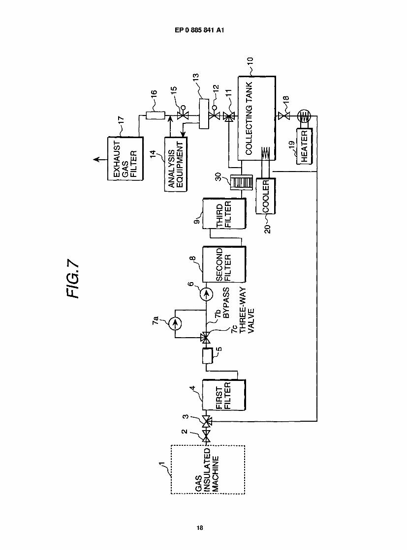
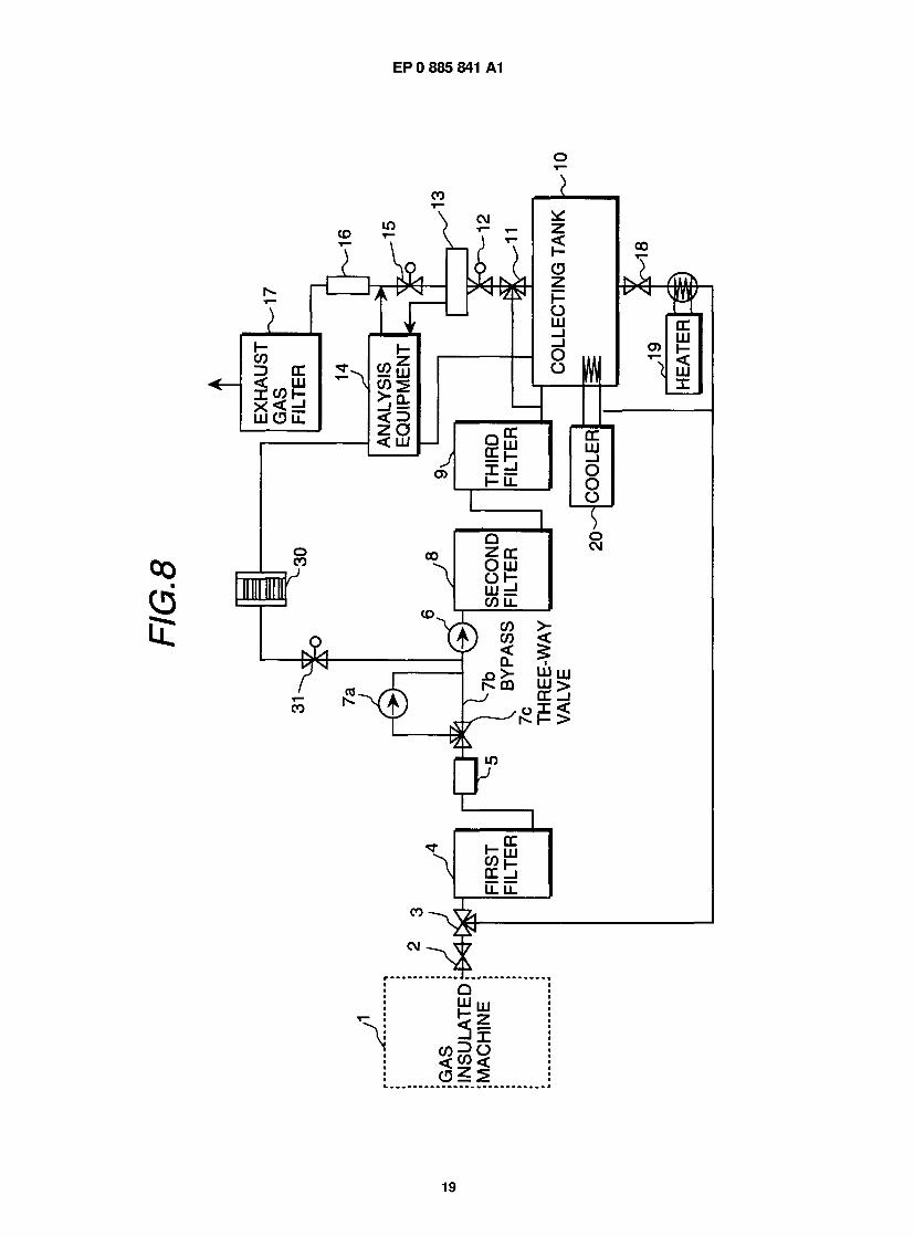
25 FIG. 7 is a diagram showing the construction of a fourth embodiment of a system for collecting and refining SF6 gas using a film filter in accordance with the present invention; and FIG. 8 is a diagram showing the construction of a modification of the embodiment of FIG. 7 of a system for collect- ing and refining SF6 gas using a film filter.
30 Description of the Preferred Embodiments
A first embodiment of the present invention will be described below, referring to FIG. 1 to FIG. 3. FIG. 1 is a diagram showing the construction of a first embodiment of the system for collecting and refining SF6 gas. FIG. 2 is a graph show- ing the relationship between collecting processing time and compressor inlet pressure. FIG. 3 is a graph showing the
35 relationship between collecting processing time and collecting and processing rate of insulating gas. The system for collecting and refining SF6 gas of this embodiment is constructed as follows. As shown in FIG. 1 , a
gas insulated machine 1 is connected to a first filter 4 through a dividing valve 2 and a dividing three-way valve 3. An insulating gas, SF6 , of 1 0 m3 at 5 kg/cm2 is filled in the gas insulated machine 1 . The first filter 4 is connected to a sec- ond filter 8 through a constant flow rate supplier 5 and a compressor 6. A vacuum pump 7a and a by-pass pipe 7b are
40 arranged between the constant flow rate supplier 5 and the compressor 6 in parallel, and a flow path of the vacuum pump 7a or the by-pass pipe 7b is selected through a three-way valve 7c. The three-way valve 7c connects the constant flow rate supplier 5 and the compressor 6 through the by-pass pipe 7b in the initial stage of operation, and connects the constant flow rate supplier 5 and the compressor 6 through the vacuum pump 7a when the pressure in the gas insulated machine 1 is decreased. Here, a pressure reducing valve is used as the constant flow rate supplier 5. The second filter
45 8 is connected to a third filter 9. The third filter 9 is connected to a collecting tank 1 0 having a cooler 20, and the collect- ing tank 10 is connected to a sampling header 13 through a sampling position switching valve 1 1 and a pressure reduc- ing valve 12. The sampling header 13 is connected to an analysis equipment 14 and also connected to a flow meter 16 through an exhaust gas valve 1 5. Further, the analysis equipment 1 4 and the flow meter 1 6 are connected to each other in the downstream of the exhaust gas valve 15. The flow meter 16 is connected to an exhaust filter 17. On the other
so hand, the collecting tank 10 is connected to the dividing three-way valve 3 through a discharge valve 18 and a heater 19, and a branch portion is arranged between the heater 19 and the three-way valve 3, and the branch portion is con- nected to the sampling position switching valve 1 1 .
Operation of the system for collecting and refining SF6 gas constructed as described above will be described below. A deteriorated insulating gas in the gas insulated machine 1 is supplied to the first filter through the three-way valve by
55 opening the dividing valve 2. The pressure reducing valve as the constant flow rate supplier 5 is fully closed. When the dividing valve 2 is opened and the inlet pressure at the constant flow rate supplier 5 becomes nearly equal to the pres- sure in the gas insulated machine, the pressure reducing valve is gradually opened and controlled so that the outlet pressure of the pressure reducing valve becomes 1 .5 kg/cm2. Under this state, the compressor 6 is started to operate
5

EP 0 885 841 A1
to start collecting of the SF6 gas. Since the pressure reducing valve is controlled so as to maintain the inlet pressure of the compressor to 1 .5 kg/cm2, the collecting capacity of the compressor 6 is maintained at a constant value. Therefore, the collecting and processing rate of the SF6 gas can be maintained to a constant value. Thereby, required amounts of adsorbent, neutralizer and the like can be minimized to necessary and minimum values. For example, the collecting
5 amount of the SF6 gas per unit time in the initial stage is set to 1 N m3/min. Further, a fluid resistor such as an orifice or the like may be used as the constant flow rate supplier 5.
Since among impurities contained in the gas it is necessary to separate acidic gases and solid components such as fluorides and sulfides which are ill affect to machines, the neutralizing and removing agent is arranged inside the first filter 4 at a place in the upstream side of the compressor 6 and the vacuum pump 7. Since the first filter 4 is depressu-
10 rized to a negative pressure of 10 Torr in the last stage, a neutralizing and removing agent of a physically adsorbing type is not preferable but a neutralizing and removing agent of a calcium group alkali base is preferable. The reason is that the neutralizing and removing agent of a physically adsorbing type has a characteristic of discharging substances once having been adsorbed under a depressurized condition, and accordingly activated carbon is not suitable. Therefore, in this embodiment, a granular neutralizing and removing agent having main components of CaO and Ca(OH)2 is used.
15 The neutralizing and removing agent fixes the acidic gases as calcium salts, and water produced by the fixing reaction is absorbed in CaO and carbon dioxide is also fixed and removed as carbonic salts by CaO and Ca(OH)2. A quantity of the neutralizing and removing agent to a quantity of the gas to be processed is set to SV = 500 h"1 . Since the processing rate of the gas is 1 N m3/ min (60 N m3/ h), the quantity of the neutralizing and removing agent becomes approximately 120 liters. By doing so, the concentration of acidic gas after processed can be reduced below 1 ppm. Further, the solid
20 components of fluorides and chlorides are also filtered and removed by the granular adsorbent layer. An adsorbent selectively adsorbing a strong acidic gas of HF gas is contained in the first filter 4 to adsorb HF gas
while the insulating medium is passing through the vessel of the first filter and to neutralize the insulating medium as a result. The method of neutralizing can be employed is a general neutralizing method of allowing the gas to pass through an alkaline solution. A dry neutralizing method of using an adsorbent can improve handling capability since no alkaline
25 solution is used. By using the granular neutralizing and removing agent having main components of CaO and Ca(OH)2 to the first
filter, the acidic gas after-processed can be removed and the water produced in an approximately equivalent quantity of the acidic gases accompanied by removing the acidic gases can be also removed. Further, carbon dioxide and solid components can be also removed and separated. Since the removal is performed by chemically changing the acidic
30 gases and the like to the other substances to fix and separate, the removed substances cannot be released again even if the pressure of the first filter is depressurized down to near a vacuum during the collecting operation. In addition to these, since the components and the pipes in the system line up to the first filter 4 is exposed to the acidic gases, the components and pipes are protected by nickel plating (Kanigin plating) or the like.
The gas removed the acidic gases by the first filter 4 is supplied to the second filter 8 through the compressor 6. An 35 adsorbent composed of activated carbon or zeolite as the main component is used for the second filter 8. The second
filter 8 is arranged for backing up the first filter 4 and for adsorbing and separating by-product gases other than the acidic gases. The second filter 8 cannot be not brought in a negative pressure condition since it is arranged in the down- stream side of the compressor 6 and the vacuum pump 7, and accordingly the substances once adsorbed and sepa- rated cannot be released again. Since an activity of adsorbing reaction of the activated carbon or the zeolite is high, the
40 amount of the adsorbent of the second filter 8 is 60 liters by setting SV = 1 000 h" 1 . The gas of which the by-product gases have been adsorbed and separated by the second filter is supplied to the
third filter 9. In the third filter 9, a molecular sieve is used for removing moisture, and the moisture concentration can be reduced to nearly zero by the back-up of the first filter 4. Since the absorbing characteristic of the molecular sieve is excellent, the amount of the molecular sieve is 30 liters by setting SV = 2000 h"1.
45 The deteriorated SF6 gas processed by the individual filters as described above is collected and stored in the col- lecting tank 1 0 by being cooled and liquefied using the cooler 20. The SF6 gas in the collecting tank 1 0 is separated into gas phase and e liquid phase, and a part of the SF6 gas in gas phase in the upper portion of the collecting tank 10 is supplied to the analysis equipment 14 through the pressure reducing valve 12 and the sampling header 13 to perform composition analysis of the collected gas. Since the SF6 gas is cooled and liquefied, non-condensable gases are gath-
50 ered to the SF6 gas in gas phase in the upper portion of the collecting tank 10 to increase the impurity concentration. The analysis equipment 14 comprises an acidic gas detector, a gas chromatograph, an oxygen meter and a dew point meter. The concentration of the acidic gases is measured by the acidic gas detector, and the concentrations of the car- bon dioxide and the PFC gas are measured by the gas chromatograph. Further, the concentration of the air is meas- ured by the oxygen meter, and the concentration of the moisture is measured by the dew point meter.
55 The supply of gas to the analysis equipment 14 is continuously performed, and accordingly the latest gas compo- sition of the collected gas is analyzed and confirmed. The gas after completed the analysis is discharged to the external through the exhaust gas filter 1 7 which is filled with activated carbon or the like. The SF6 gas is adsorbed in the exhaust gas filter 1 7 to prevent the SF6 gas having a large global worming property coefficient from leaking to outside the sys-
6
EP 0 885 841 A1
tern. Otherwise, instead of using the exhaust gas filter 1 7, the exhaust gas may be collected into a vinyl bag or the like and the collected gas may be burned in an incinerator since the quantity of the exhaust gas is small.
If it is judged from the analysis result of the gas compositions by the analyzing equipment 1 4 that the purity of the gas does not reach the target value, the discharge valve 18 of the collecting tank 10 is opened, and the liquefied gas is
5 heated with the heater 1 9 to be vaporized and returned to the first filter 4 through the dividing three-way valve 3. As described above, the process of confirming the compositions and the process of returning the collected SF6 gas
to the first filter until the compositions become the target values. Although air among the impurities leaks and mixes into the system, it is difficult to separate some of non-conden-
sable gases such as air by adsorbing and removing. Therefore, if a result of the analysis shows that the concentration 10 of air is high, the impurities such as air is selectively exhausted by opening the exhaust gas valve 1 5 to exhaust the gas
in the gas phase of the collecting tank while the flow rate is being confirmed using the flow meter 16 because air (02, N2) is a non-condensable gas having a lower condensing temperature compared to SF6 gas and exists in the gas phase. PFC gas and carbon dioxide having lower condensing temperatures compared to SF6 gas can be also selec- tively exhausted to the external in the similar manner. In that time, the SF6 gas is prevented from being discharged out-
15 side the system by the exhaust gas filter 1 7. Further, similar to the above, the exhaust gas may be collected into a vinyl bag or the like and the collected gas may be burned in an incinerator since the quantity of the exhaust gas is small.
As the collection of the SF6 gas is progressed in the manner as described above, pressure in the gas insulated machine 1 is gradually decreased and becomes lower than a set value of the pressure reducing valve as the constant flow rate supplier 5. Although the pressure reducing valve is in the fully opened state at that time, the collecting rate is
20 decreased lower than the preset value and cannot exceed the design flow rate of the filter because the efficiency of the blower is decreased due to lowering of the pressure. The collection of the SF6 gas is further progressed, and at the time when the pressure reaches approximately -0.1 to -0.2 kg/cm2, the vacuum pump 7 is started to operate and the SF6 gas is collected using the both machines. Finally, the SF6 gas is collected as much as possible by reducing the pressure inside the gas insulated machine 1 up to 10 Torrs. By doing so, the amount of the remaining SF6 gas inside the gas
25 insulated machine 1 can be reduced and accordingly the amount of discharged SF6 gas can be reduced. At the time of completion of collection, the final analysis of composition of the collected gas is performed to confirm that the compo- sition is within the range of the required condition. Then, the gas insulated machine is opened to perform inspection and maintenance of the inside portions. After completion of the inspection and maintenance, the inside of the gas insulated machine 1 is evacuated to 10 Torrs to exhaust the air inside the gas insulated machine 1. Then, the collected and
30 refined SF6 gas is refilled in the gas insulated machine 1 . The refilling is performed by opening the exhaust valve 18 and heating and gasifying the cooled and liquefied SF6
gas using the heater 19 to supply the SF6 gas to the gas insulated machine 1. At that time, the composition of the refilled gas is analyzed and confirmed by switching the sampling position switching valve 1 1 .
The SF6 gas gasified by the heater 19 is supplied to the gas insulated machine 1 through the dividing three-way 35 valve 3 and the dividing valve 3. In a case where the analysis result of the gas composition after collection and refining
of the SF6 gas shows that the purity of the gas is not sufficient, similar to the case of refilling after opening the exhaust valve 18 and heating and gasifying the cooled and liquefied SF6 gas using the heater 19, the SF6 gas is supplied to the first filter 4 through the dividing three-way valve 3 to repeat the same process as the process at collecting and refining time.
40 New SF6 gas is additionally supplied from a compressed gas cylinder by the amount of the SF6 gas consumed by being decomposed inside the gas insulated machine 1 and the amount of the SF6 gas consumed by the analysis and the like so that a necessary amount of SF6 gas is filled in the gas insulated machine. Further, the SF6 gas adsorbed to the activated carbon in the exhaust gas filter 17 is burning-treated together with the activated carbon and not dis- charged outside the system.
45 By removing and separating the by-produced impurity gases contained in the deteriorated SF6 gas not by wet but by the dry processing as described above, the system for collecting and refining SF6 gas of this embodiment can be made small not only in the size of the adsorbing and removing components but also in the size of the total system. For example, when calcium hydroxide of 100 g is used as the saturated aqueous solution, the volume becomes approxi- mately 63 liters because the solubility is small. When calcium hydroxide of 100 g is used as a 5 % concentration aque-
50 ous solution, the volume becomes approximately 2 liters. However, it is necessary to stir the solution uniformly. On the other hand, when calcium hydroxide is formed in granular shape or particle shape and used by dry method, volume of calcium hydroxide of 100 g is approximately 0.14 liter since the bulky density is approximately 0.7 g/cc. Even if the avail- able efficiency is assumed to be nearly 70 % because of dry method, the volume becomes only approximately 0.2 liter. By treating the gas by the dry method as described above, the volume of the system can be reduced below 1/10. Fur-
55 ther, the amount of the secondary waste can be also reduced below 1/1 0, and can be easily handled because no liquid waste is produced.
In addition to these, it is preferable from the viewpoint of work efficiency that the work of collecting the SF6 gas from the gas insulated machine is performed at the installation site of the gas insulated machine, and after completion of
7
EP 0 885 841 A1
inspection the refined SF6 gas collected from the gas insulated machine is refilled to the gas insulated machine. How- ever, it is generally necessary that the measurement of the collected SF6 gas is performed by sending the samples to a factory or a place where an analysis equipment is placed to be measured. Since the work needs to be temporary stopped in such a case, new SF6 gas is often filled in the gas insulated machine. This is because the gas insulated machine is an electric supply infrastructure apparatus which is required to be recovered in a short time.
The system for collecting and refining SF6 gas of this embodiment has an equipment capable of quantitatively ana- lyzing and measuring the compositions of the collected and refined SF6 gas in place, and accordingly it is possible to judge at the collecting site whether or not the SF6 gas is reusable and to smoothly perform reuse of the SF6 gas. That is, the measurement of the gas can be performed by selecting a measurement apparatus for each of the gases as shown in Table 4. By combining the analysis equipment for gas composition with the system for collecting and refining SF6 gas and by measuring and confirming the composition of the gas after collecting and refining in place in a short time, as described above, after refining the collected SF6 gas the refined gas can be speedy and effectively reused.
Table 4
Examples of applicable measurement apparatus No. Item Measurement Apparatus Measurable Lower Limit
(ppm) 1 Acidic gases Acidic gas detector, Gas chromatograph approximately 0.5
2 Carbon dioxide Gas chromatograph approximately 0.5
3 PFC Gas chromatograph approximately 10
4 Air Oxygen meter approximately 10
5 Humidity Dew point meter, Humidity meter approximately 5
A key point of improving work efficiency in the conventional system is how to collect the SF6 gas in a short time, and consideration is paid only on collecting the SF6 gas, but not on averaging the collecting flow rate. However, in order to reuse the SF6 gas, how to refine the SF6 gas to a high purity is an important factor to improve the work efficiency. If the purity is low, the SF6 gas cannot be reused or the SF6 gas needs to be refined again.
The maximum flow rate during collecting period occurs in the initial period of the collecting work. That is, the max- imum flow rate during collecting period occurs in a period of 1 to 2 minutes when the pressures in the gas insulated machine and the collecting tank become in balance after connecting the gas insulated machine filled with SF6 gas to the collecting tank with a communicating pipe and opening the communicating pipe, and in the following short period when the compressor for collecting the gas is started to operate and the pressure inside the gas insulated machine is reduced to a certain value. Since the compressor more efficiently collects the gas as the pressure in the suction side is higher, the efficiency is decreased as the pressure in the suction side decreases and consequently the collecting flow rate is reduced as the pressure in the suction side decreases. The maximum flow rate occurs in the period of opening the communicating pipe and the following short period after starting the compressor. Therefore, by performing constant flow rate control of the collecting flow rate during those periods, the collecting time is lengthened by 10 to 20 % com- pared to that in the conventional system. However, the collecting flow rate can be made constant and averaged, the processing system can be made small in size, and the refining processing can be improved.
In the past, collection of the SF6 gas has been performed in a manner as shown by the broken line in FIG. 5. That is, collection of the SF6 gas is started when the inlet pressure of the compressor of the collecting system is a value equal to the pressure in the gas insulated machine, and the inlet pressure is rapidly decreased as shown in FIG. 2 as the collection of the SF6 gas is progressed. During the period, the collecting flow rate changes along the curve shown in FIG. 3 which is similar to the pressure change shown in FIG. 2. However, the maximum process capacity of the refin- ing apparatus needs to have a process capacity meeting to the point A.
On the other hand, according to the present invention, since the pressure reducing valve 5 is arranged in the inlet of the compressor 6 of the collecting system and the SF6 gas is collected with keeping the inlet pressure of the com- pressor 6 and controlling the collecting flow rate to a constant flow rate, the collecting characteristic becomes as shown by the solid line in FIG. 5. Since the inlet pressure of the compressor is kept constant at the value of the point B, the collecting flow rate is also kept constant. When the pressure in the gas insulated machine side is decreased lower than a preset value of the pressure reducing valve, the pressure reducing valve is fully opened at the point D and the inlet pressure of the compressor is decreased to decrease the collecting flow rate. By doing the constant flow rate control of the collecting flow rate, the time period necessary for collecting and refining the SF6 gas is lengthened by At, but it is
8
EP 0 885 841 A1
lengthened only by 10 to 20 % compared to the total time period. By doing so, the process capacity of the system for collecting and refining can be reduced from the point A to the point C. Thereby, the necessary process capacity can be reduced to 1/3 to 1/4.
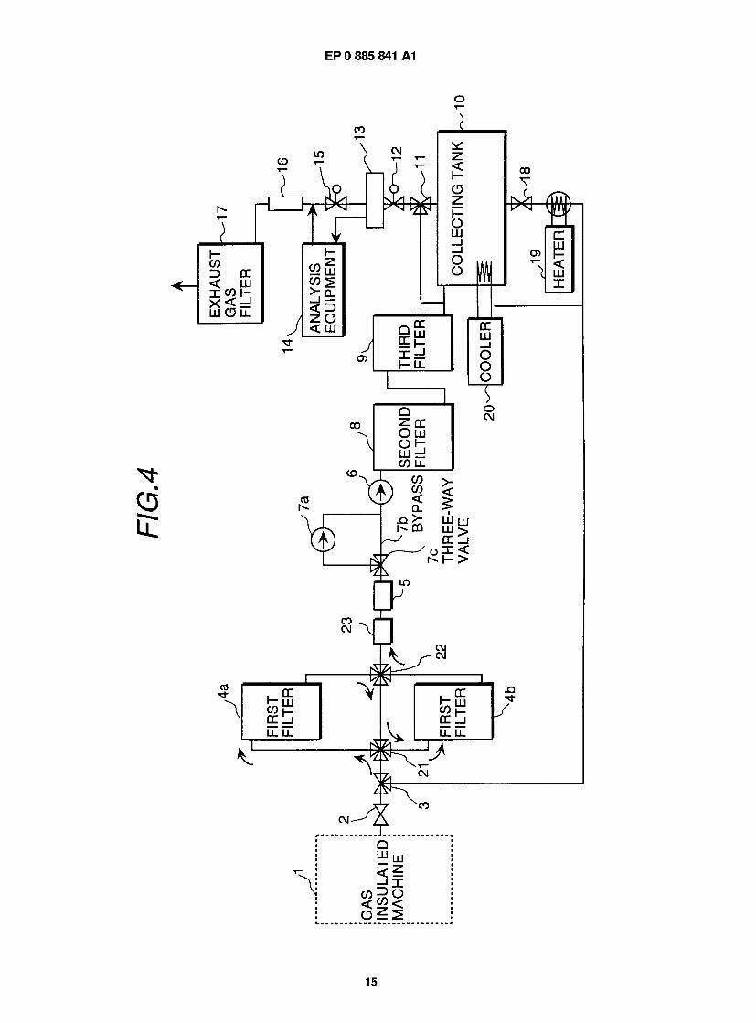
A second embodiment of the present invention will be described, referring to FIG. 4 and FIG. 5. FIG. 4 is a diagram 5 showing the construction of this embodiment of a system for collecting and refining SF6 gas. FIG. 5 is a graph showing
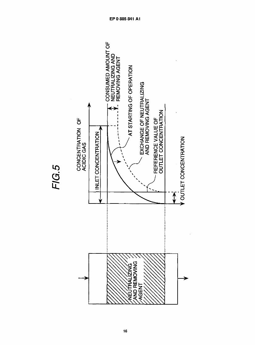
change of concentration of processed gas with operation of a neutralizing and removing agent. The system for collecting and refining SF6 gas of this, embodiment is constructed similarly to the embodiment
shown in FIG. 1. However, in this embodiment, a four-way switching valve 21 and a four-way switching valve 22 are arranged in the downstream side of the dividing three-way valve 3, and two first filters 4a, 4b are arranged in parallel
10 through the four-way switching valve 21 and the four-way switching valve 22. The two first filters 4a, 4b are connected double in parallel as shown in FIG. 4 to improve the availability of the neutralizing and removing agent.
It is confirmed that the concentration of the acidic gases is the highest among the impurities in the deteriorated SF6 gas from an inspection and analysis result of compositions of the deteriorated SF6 gas. In a case of adsorption or reac- tion fixing, an effective amount of the adsorbent or the neutralizing and removing agent is decreased with operation and
15 the adsorbent needs to be exchanged because of reducing of the removing efficiency. It can be understood from FIG. 5 showing change of concentration of the processed gas with operation of the neutralizing and removing agent that when processing is performed by filling a designed amount of the neutralizing and removing agent, the concentration of the acidic gases is gradually decreased in the inside of the filter and at the outlet the acidic acid can be removed below a desired concentration, as shown by the solid line. However, when the neutralizing and removing agent in the
20 inlet portion of the filter is gradually consumed with operation, the concentration of the acidic gases inside the filter changes as shown by the broken line and the filled neutralizing and removing agent needs to be exchanged in order that the concentration of the acidic gases at the outlet attains the reference concentration. In this case, although the amount of the consumed neutralizing and removing agent is far less than a half of the total amount, the whole amount of the filled agent needs to be exchanged because the initial performance as the filter cannot be displayed.
25 Therefore, in this embodiment, two sets of the first filters filled with Ca group alkali having the largest load are used by arranging them in series as shown in FIG. 4. The collected SF6 gas is initially supplied to the first filter 4a by switching the flow path using the four-way switching valve 21 . The deteriorated SF6 gas having passed through the first filter 4a is supplied to the first filter 4b through the four-way switching valve 22 and the four-way switching valve 21 to remove the acidic gases.
30 When the concentration of the acidic gas exceeds the reference value by monitoring the outlet concentration of the acidic gas using an acidic gas monitor 23, the neutralizing and removing agent filled in the first filter 4a is exchanged and the flow path is changed so that the deteriorated SF6 gas flows through in order of the four-way switching valve 21 , the first filter 4b, the four-way switching valve 22, the four-way switching valve 21 , the first filter 4a, the four-way switch- ing valve 22 and the compressor 6. By operating in such a manner, the total amount of the neutralizing and removing
35 agent in each of the filters can be consumed out, and consequently the amount of the neutralizing and removing agent used can be reduced to approximately 1/2 compared to in a case of operating one set of the filter. As a result, in addition of the reduction in the procurement cost of the neutralizing and removing agent, the disposal cost of the secondary waste can be reduced to 1/2 and the system can be made smaller since the availability of the neutralizing and removing agent can be increased twice.
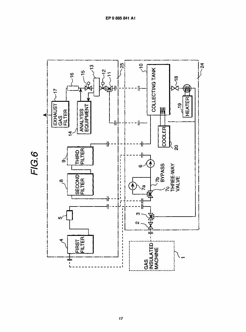
40 A third embodiment of the present invention will be described, referring to FIG. 6. FIG. 6 is a diagram showing the construction of this embodiment of a system for collecting and refining SF6 gas.
As shown in FIG. 6, the collecting and refining system of this embodiment is constructed by combining an existing SF6 gas collecting system 24 and an existing SF6 gas refining system 25. In order to collect the SF6 gas from the gas insulated machine, the SF6 gas collecting system 24 is used. The existing SF6 gas collecting system 24 is designed not
45 in taking the refining process into consideration, but has only a function to collect the SF6 gas from the gas insulated machine 1 . By adding a gas refining function to this system, the existing system can be effectively used as a series of systems for collecting and refining SF6 gas. The added SF6 gas refining system 25 is mainly composed of filters and a composition analysis equipment 14 for collected gas.
The SF6 gas collecting system 24 collects the SF6 gas from the gas insulated machine 1 to the collecting tank 10 so through the dividing valve 2 and the dividing three-way valve 3 using the compressor 6 and the vacuum pump 7, and
the collected SF6 gas is cooled in the collecting tank 10 by the cooler 20 to be liquefied. When the gas is refilled, the SF6 gas is supplied to the gas insulated machine 1 through the dividing three-way valve 3 and the dividing valve 2 by opening the discharge valve 18 of the collecting tank 10 and heating using the heater 19 to evaporate the SF6 gas.
When the SF6 gas collecting system 24 and the SF6 gas refining system 25 are combined, the system structure 55 and the operation become as follows. The SF6 gas in the gas insulated machine 1 is supplied to the first filter 4 through
the dividing valve 2 and the dividing three-way valve 3. The dividing three-way valve 3 and the first filter 4 is connected by a pressure resistant and vacuum proof hose or pipe. The SF6 gas passed through the first filter 4 is supplied to the compressor 6 or the vacuum pump 7 of the SF6 gas collecting system 24 from the SF6 gas refining system 25 through
9
EP 0 885 841 A1
the constant flow rate supplier 5. The SF6 gas compressed by the compressor 6 or the vacuum pump 7 is supplied to a second filter 8 and a third filter 9 to remove impurities and then stored in the collecting tank 10. In the collecting tank 10, the SF6 gas is cooled to be liquefied.
By separating into the collecting system and the refining system as the SF6 gas collecting system 24 and the SF6 5 gas refining system 25, each system can be made small and made better in portability. Further, when there is an exist-
ing collecting system, a series of collecting SF6 gas and refining SF6 gas can be performed by adding a new SF6 gas refining system 25.
A fourth embodiment of the present invention will be described, referring to FIG. 7 and FIG. 8. Each of FIG. 7 and FIG. 8 is a diagram showing the construction of this embodiment of a system for collecting and refining SF6 gas.
10 The system for collecting and refining SF6 gas of this embodiment is constructed similar to the embodiment shown in FIG. 1 . However, in the system for collecting and refining SF6 gas of this embodiment, a fourth filter 30 is arranged between the third filter 9 and the collecting tank 1 0. In the fourth filter 30, a porous hollow thread film for selectively sep- arating air is installed.
A produced amount, that is, a concentration of gas component composition produced in the deteriorated SF6 gas 15 in which SF6 gas is deteriorated is seldom deviated largely from the values shown in Table 3. However, air enters into
the system by in-leakage from the outside of the system, and the concentration of air possibly becomes 1 00 times or 1000 times of the concentration shown in Table 1 if even one of fastened positions is loosed. Further, in order to reduce an amount of SF6 gas discharged to atmosphere, before releasing the gas insulated machine, the inside of the system other than the gas insulated machine is brought to a considerable vacuum condition in order to evacuation-collect SF6
20 gas as much as possible. In this condition, potential of air to leak into the system from outside the system is increased. On the other hand, air containing N2, 02 can be adsorbed and removed to a certain degree by an adsorbent of
active carbon group, but the amount is as small as approximately 1 % of the amount of the adsorbent. Therefore, the air soon breaks through the absorbent. The air may be discharged out of the system from the collecting tank 10 as a non-condensable gas. However, this case is not preferable because the SF6 gas is also released outside the system
25 together with the air. Therefore, it is necessary to selectively separate and remove only the air among the collected gases.
This embodiment realizes the selective separation and removal of the air using a porous hollow thread film having selective property. The acidic gases and the carbon dioxide gas accompanied by the SF6 gas are removed by the first filter 4, and the by-product gases are removed in the second filter 8. Further, the moisture is removed in the third filter
30 9. The air containing N2, 02 is separated and removed by the porous hollow thread film filter in the fourth filter 30. This makes use of that the molecular diameters of N2, 02 gases are smaller than the molecular diameters of SF6 gas, and only N2, 02 gases are separated and released outside the system using the film having a hole diameter through which N2, 02 gases pass but SF6 gas does not pass. The gas is pumped into the fourth filter 30 by the compressor 6. There- fore, it is sufficient to place the film having the required property and no driving source for pressurizing the supplied gas
35 is necessary because a positive pressure acts in the forth filter. Different from the filter of filling agent type, the film filter can cope with a large amount of air in-leaking because the film filter cannot be broken through by the air, and the film filter does not produce the secondary waste such as a disposed filling agent (disposed adsorbent).
In the embodiment shown in FIG. 8, the fourth filter 30 is arranged between the collecting tank 10 and the inlet of the compressor 6, and a branch portion is arranged in a position of the upstream side of the compressor 6 and the
40 downstream side of the vacuum pump 7, and the forth filter 30 is connected to the branch portion through a pressure reducing valve 31 . The fourth filter 30 is further connected to the analysis equipment 14, and the porous hollow thread film is arranged for selectively separate air is installed in the fourth filter 30.
In the embodiment shown in FIG. 8, the gas passes through the fourth filter 30 only once. In the system of FIG. 8, a predetermined amount of the gas is re-circulated by supplying the gas from the gas phase portion of the collecting
45 tank 1 0 where the concentration of air of a non-condensable gas is high to the inlet portion of the compressor 6 through the pressure reducing valve 31 . The re-circulation flow rate is controlled by the pressure reducing valve 31 . Since the collecting tank 10 in this case is in a positive pressure, no driving source for applying a positive pressure to the film is necessary.
As described above, the efficiency of separating and removing the air can be substantially improved by re-circulat- 50 ing the gas in the gas phase portion where the concentration of air of a non-condensable gas is high in the collecting
tank 10 and processing the gas using the fourth filter 30. Further, since this filter is of a film separating type, the sec- ondary waste is not produced.
According to the system for collecting and refining SF6 gas of the present invention, the deteriorated SF6 gas is effi- ciently collected from the gas insulated machine, and impurities accompanying with the SF6 gas are separated and
55 removed, and the composition of the collected SF6 gas can be measured and confirmed. Therefore, collecting, refining and reusing of the deteriorated SF6 gas can be speedy performed at the installation site of the machine. Thereby, it is possible to prevent the SF6 gas harmful to the global environment from releasing to atmosphere, and to make effective use of resources. Further, by using the dry type filter for the refining process, it is possible to make the system small in
10
EP 0 885 841 A1
size, to keep the portability of the system and to reduce the amount of the secondary waste.
Claims
1 . A system for collecting and refining SF6 gas comprising
a first filter (4) connected to a gas insulated machine (1), a constant flow rate supplier (5) connected to the down-stream side of said first filter (4), a compressor (6) and a vacuum pump (7a) connected in parallel to the downstream side of said constant flow rate supplier (5), a collecting tank (10) connected to the downstream side of said compressor (6), and a cooler (20) for cooling said collecting tank (10),
wherein said first filter (4) is filled with a dry adsorbent.
2. The system of claim 1 , comprising a constant flow rate valve arranged at the inlet side of said compressor (6).
3. The system of claim 1 , wherein said first filter (4) is filled with a calcium group alkali.
4. The system of claim 1 , comprising
at least a second filter (8) arranged between said compressor (6) and said collecting tank (10), and an analysis equipment (14) including a gaschromatograph at the downstream side of said second filter (8).
5. The system of claim 1 , comprising a returning pipe for returning SF6 gas from said collecting tank (10) to said gas insulated machine (1).
6. A method of collecting and refining SF6 gas, comprising the steps of:
removing impurities from SF6 gas from a gas insulated machine (1) by averaging the SF6 gas flow rate and let- ting the SF6 gas flow through a first filter (4) filled with a dry adsorbent, adsorbing and removing by-product gases by a second filter (8) filled with a dry adsorbent, and collecting the SF6 gas separated by said second filter (8) by cooling and liquefying the SF6 gas.
7. The method of claim 6, comprising the further step of
confirming compositions of said collected SF6 gas by analysing compositions on analysis items of moisture concentration, acidic gas concentration, carbon dioxide concentration, any one of oxygen and nitrogen con- centration and PFC concentration, and repeating said process of confirming said compositions and returning said collected SF6 gas to said first filter (4) until said compositions become target values.
CO z>
OIL |
T"
< l
Ml
i— i i i
_ J O
I
/ I I "
EP 0 885 841 A1
r
W LU c o s >- n
CO
3
u_
H I
T o CM
o I - <
2 LU o 2 o o H LU _l
_ . - . | -
1 1
< > r
?
i
J LU
c c c
1 5 « l -u- I <
3 1
i 3
J !
J O E |
- L 2
05 L i
I H O LU
J
LU I _J I o
n 8
EP 0 885 841 A1
European Patent Office
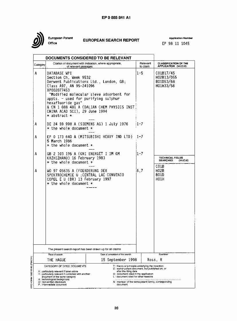
EUROPEAN SEARCH REPORT Application Number EP 98 11 1045
DOCUMENTS CONSIDERED TO BE RELEVANT
Category] Citation of document with indication, where appropriate, of relevant passages
Relevant to claim
CLASSIFICATION OF THE APPLICATION (lnt.CI.6)
DATABASE UP I Section Ch, Week 9532 Derwent Publications Ltd., London, GB; Class A97, AN 95-241096 XP002077453
"Modified molecular sieve adsorbent f o r appts. - used for purifying sulphur hexafluoride gas" & CN 1 088 481 A (DALIAN CHEM PHYSICS INST CHINA ACAD SCI), 29 June 1994 * abstract *
DE 24 59 998 A (SIEMENS AG) 1 July 1976 * the whole document *
EP 0 173 640 A (MITSUBISHI HEAVY IND LTD) 5 March 1986 * the whole document *
GB 2 103 195 A (GNI ENERGET I IM GM KRZHIZHANO) 16 February 1983 * the whole document *
W0 97 05635 A (FOERDERUNG DER SPEKTROCHEMIE U ; CENTRAL LAC CONVENIO COPEL E U (BR) 13 February 1997 * the whole document *
1-5 C01B17/45 H02B13/055 B01D53/68 H01H33/56
1-7
1-7
1-7
6 ,7
TECHNICAL FIELDS SEARCHED (lnt.CI.6)
C01B H02B B01D H01H
The present search report has been drawn up for all claims Place of search
THE HAGUE Date of completion of the search 15 September 1998
Examiner Ross, R
CATEGORY OF CITED DOCUMENTS X : particularly relevant rf taken alone Y : particularly relevant if combined with another
document of the same category A : technological background 0 : non-written disclosure P : intermediate document
T : theory or principle underlying the invention E : earlier patent document, but published on, or after the filing date D : document cited in the application L : document cited for other reasons & : member of the same patent family, corresponding document
20