SCK Sample conditioning for kiln - ABB
244
— ABB MEASUREMENT & ANALYTICS | OPERATING INSTRUCTION | OI/SCK-EN REV. E SCK Sample conditioning for kiln Sampling system for dry gas sampling at rotary cement kiln gas exit and calciner gas exit Measurement made easy — SCK Introduction The SCK is a sampling system for dry gas sampling at rotary kiln exit and calciner gas exit. The SCK sampling system is suitable for applications in rough environmental conditions and for outdoor installations thanks to a complete protection cover. Additional Information Additional documentation on SCK is available for download free of charge at www.abb.com/analytical. Alternatively simply scan this code:
-
Upload
khangminh22 -
Category
Documents
-
view
4 -
download
0
Transcript of SCK Sample conditioning for kiln - ABB

— A B B M EA S U R E M E NT & A NA LY TIC S | O PE RA TING INS TR U C TIO N | O I/ S C K - E N R E V . E
SCK Sample conditioning for kiln
— ABB Measurement & Analytics For your local ABB contact, visit: www.abb.com/contacts For more product information, visit: www.abb.com/analytical
Sampling system for dry gas sampling at rotary cement kiln gas exit and calciner gas exit
Measurement made easy
OI/
SCK
-EN
Rev
. E
07.
2021
O
rig
inal
inst
ruct
ion
— SCK Introduction
The SCK is a sampling system for dry gas sampling at rotary kiln exit and calciner gas exit. The SCK sampling system is suitable for applications in rough environmental conditions and for outdoor installations thanks to a complete protection cover.
Additional Information Additional documentation on SCK is available for download free of charge at www.abb.com/analytical. Alternatively simply scan this code:
— We reserve the right to make technical changes or modify the contents of this document without prior notice. With regard to purchase orders, the agreed particulars shall prevail. ABB does not accept any responsibility whatsoever for potential errors or possible lack of information in this document. We reserve all rights in this document and in the subject matter and illustrations contained therein. Any reproduction, disclosure to third parties or utilization of its contents – in whole or in parts – is forbidden without prior written consent of ABB. © ABB 2021 3KXG141003R4201

2 Operating instruction SCK Gas Sampling System OI/SCK-EN Rev. E
Contents
Chapter 1 General .................................................................................................................... 5 About these operating instructions .......................................................................... 6 Safety instructions in this document ........................................................................ 8 System identification .................................................................................................. 10 Service ............................................................................................................................ 13
Chapter 2 Description of the sampling system ................................................................. 15 Technical data ............................................................................................................... 16 Intended conditions of use ........................................................................................ 17 Structure and function ................................................................................................ 18 Mode of functioning and operating modes ............................................................ 19 Process monitoring .................................................................................................... 20 Controls and displays .................................................................................................. 22 Probe retractor ............................................................................................................ 24 Gas sampling probe H ................................................................................................ 26 Gas sampling probe 60S ............................................................................................ 28 Cooling module ........................................................................................................... 30 Transformer .................................................................................................................. 32 Compressed-air tank and pneumatic system ......................................................... 33
Chapter 3 Description of control system ........................................................................... 35 Structure and function of the control system ....................................................... 36 User interface: Operation screen ............................................................................. 38 User interface: Trend screen ..................................................................................... 40 User interface: Message screen................................................................................ 42 User interface: Parameter screen............................................................................. 44 Error message display ................................................................................................ 46 Access permissions .................................................................................................... 47 Default operating parameter settings .................................................................... 48 Optimizing operating parameters ............................................................................ 51
Chapter 4 Safety.................................................................................................................... 53 Basic safety rules ........................................................................................................ 54 Overview of dangers .................................................................................................... 57 Protective installations .............................................................................................. 59 Warning signs on the system .................................................................................... 63 Requirements to be met by personnel, work places ............................................ 65 Personal safety equipment ........................................................................................67 Safety measures: Transport and unpacking .......................................................... 68 Safety measures: Installation ................................................................................... 69 Safety measures: Start-up .......................................................................................... 72 Safety measures: Operation ......................................................................................76 Safety measures: Maintenance and troubleshooting .......................................... 80
Chapter 5 Transport and unpacking ................................................................................... 85 General transport information ................................................................................. 86 Transport the system in the company .................................................................... 89 Unpacking the system ................................................................................................. 91

OI/SCK-EN Rev. E Operating instruction SCK Gas Sampling System 3
Scope of delivery ......................................................................................................... 92
Chapter 6 Installation ........................................................................................................... 93 Overview: installation ................................................................................................. 94 Checking site conditions ........................................................................................... 95 Installing the probe retractor ....................................................................................97 Installing the control cabinet .................................................................................. 100 Installing the compressed-air supply ..................................................................... 101 Installing the cooling module.................................................................................. 103 Installing the cooling water circuit ........................................................................ 104 Connecting the sample gas line to the retractor ................................................ 105 Connecting internal electric cables ....................................................................... 106 Connecting external electric cables ....................................................................... 108
Chapter 7 Start-up ...............................................................................................................111 Overview: Start-up ..................................................................................................... 112 Installation check ....................................................................................................... 113 Preparing the cooling-water circuit ........................................................................ 114 Preparing the compressed-air supply .................................................................... 116 Activation ..................................................................................................................... 118 After switching on: working on the cooling module ........................................... 121 Checking the pneumatic system ............................................................................. 123 Starting frequency converter and adapting control parameters...................... 124 Checking/correcting operating parameters ........................................................ 126 Checks to perform when using probe H ................................................................ 127 Inserting the probe and switching to automatic mode ..................................... 130
Chapter 8 Operation ........................................................................................................... 135 Safety regulations for operation ............................................................................. 136 Monitoring automatic mode .................................................................................... 139 Checking general condition ..................................................................................... 141 Cleaning gas sampling probe H .............................................................................. 143 Cleaning gas sampling probe 60S ......................................................................... 145 Using the EMERGENCY-STOP switch ..................................................................... 147
Chapter 9 Maintenance ....................................................................................................... 149 Maintenance plan ...................................................................................................... 150 Equipment layout plan ............................................................................................. 154 Acquiring spare parts and wear parts .................................................................... 157 Safety regulations for maintenance work .............................................................158 Operating the service switch ................................................................................... 161 Checking the condition of the system, cleaning the system ............................. 163 Evaluating trend displays ........................................................................................ 166 Checking the residual current circuit breaker....................................................... 167 Checking protective installations .......................................................................... 169 Checking for leaks ...................................................................................................... 173 Gas sampling probe H: Removing incrustations .................................................. 176 Gas sampling probe H: Replacing the intake filter .............................................. 178 Gas sampling probe H: Replacing membrane pump membranes .................... 181 Gas sampling probe 60S: Removing incrustations ............................................. 184

4 Operating instruction SCK Gas Sampling System OI/SCK-EN Rev. E
Gas sampling probe 60S: Cleaning or replacing the outlet filter ..................... 186 Gas sampling probe 60S: Replacing the seal set ................................................ 189 Probe retractor: Checking filter/pressure control combination ....................... 191 Probe retractor: Checking and replacing the filter muffler ................................ 193 Probe retractor: Checking and topping up the oiler ............................................195 Probe retractor: Checking and tightening the drive chain ................................ 198 Probe retractor: Checking and, if necessary, adjusting the position of the probe ........................................................................................................................... 200 Probe retractor: Checking and, if necessary, adjusting the position indicator (probe end position) ................................................................................................. 204 Probe retractor: Checking the bellows .................................................................. 207 Cooling module: Vent the cooling-water circuit .................................................. 208 Cooling module: Checking and topping up cooling water .................................210 Pneumatic system: Replacing the compressed-air filter .................................... 213
Chapter 10 Errors .................................................................................................................. 215 Errors and irregularities ............................................................................................ 216 Touchscreen error displays ...................................................................................... 218 Handling error messages .........................................................................................223
Chapter 11 Shutting down, storing, putting back into operation, disposal ................... 225 Shutting down the system ...................................................................................... 226 Disassembling the system ...................................................................................... 229 Storing the system.....................................................................................................232 Putting the system back into operation ................................................................233 Disposing of the system .......................................................................................... 234
Chapter 12 Appendix ............................................................................................................ 235 Pneumatic/hydraulic interface plan ...................................................................... 236 Electrical connection plan........................................................................................ 238 Transformer connection plan ................................................................................. 240
Index ............................................................................................................................. 241

OI/SCK-EN Rev. E Operating instruction SCK Gas Sampling System 5
Chapter 1 General
Topic Page About these operating instructions ................................................................... 6
Safety instructions in this document ................................................................. 8
System identification .......................................................................................... 10
Service .................................................................................................................... 13

6 Operating instruction SCK Gas Sampling System OI/SCK-EN Rev. E
About these operating instructions
These operating instructions apply to the SCK gas sampling system, product number: 23919.
These operating instructions are intended to give all personnel handling the gas sampling system the information required to perform the following tasks correctly and safely:
Transport at the company (for first-time delivery, relocation, storage, putting back into operation)
Set-up, unpacking and connection Start-up Operation Diagnostics and troubleshooting Maintenance Shutting down, disassembly, putting back into operation, storage and
disposal
These operating instructions are intended for the following groups:
Process engineers and design engineers (for preparation of the installation site)
Transporter Assembly personnel Start-up personnel Operating personnel Maintenance personnel Storage personnel Disposal personnel
The illustrations in the operating instructions do not always depict the actual layout of a gas sampling system as delivered. Therefore, the drawings in the supplied system documentation are always authoritative.
Failing to observe the information in this document can lead to a risk of dam-age to property, injuries or even death.
In order to ensure safety, all personnel handling the gas sampling system must have read and understood the following sections of this document before commencing any work:
the section on Safety on page 53 the sections describing the work to be performed
Scope and purpose
Target group
Illustrations in the operating instructions

OI/SCK-EN Rev. E Operating instruction SCK Gas Sampling System 7
The manufacturer retains copyright to these operating instructions:
ABB Automation GmbH Geschäftsgebiet Analysentechnik Stierstädter Straße 5 60488 Frankfurt am Main GERMANY
These operating instructions contain regulations and drawings of a technical nature that must not, either in part or in whole, be reproduced, disseminated or exploited for the purpose of competition or passed on to third parties without permission.
The manufacturer is not liable for damage and disruptions resulting from a failure to observe these operating instructions and other applicable docu-ments.
Identifies safety information to be heeded when handling the gas sampling system in order to avoid risks to the operator.
Identifies special information regarding handling of the gas sampling system as well as use of these operating instructions.
1, 2, 3, ... Identifies reference numbers in the figures.
Further information on ABB Analytical products and services is available on the Internet at "http://www.abb.com/analytical".
Copyright
Liability
Symbols and typefaces
Further information

8 Operating instruction SCK Gas Sampling System OI/SCK-EN Rev. E
Safety instructions in this document
Safety instructions are information intended to prevent physical injuries. Safety instructions contain the following information:
Type of danger Possible consequences if you fail to observe the instruction Action to prevent physical injury
This document contains the following types of safety instruction:
Type of safety instruction
Description Indicated by
Basic safety in-structions
Generic safety instructions not pertaining to a particular task: They provide a general de-
scription of dangers and safety measures when han-dling the system.
They are intended to educate the operator about existing dangers and to instruct him in general safety behavior.
They are suitable for safety instruction of all personnel handling the gas sampling system.
Indicated by the title of the section.
Safety regulations for specific sec-tions
Safety instructions pertaining to all tasks described in this sec-tion
Indicated by the title of the section
Safety instructions at the beginning of an instruction
Safety instructions with specific instructions pertaining to the entire instruction
Safety instructions on a particular step
Safety instructions with specific instructions pertaining to one step only
DANGER WARNING CAUTION
What are safety instructions for?
Types of safety instruction

OI/SCK-EN Rev. E Operating instruction SCK Gas Sampling System 9
The safety instructions pertaining to instructions and actions are indicated by a danger word. The danger word stands for a particular danger level:
Type of safety instruction
If the instruction is not fol-lowed ...
And the consequence is ...
DANGER an accident occurs. serious bodily injury or death.
WARNING the accident may occur. possibly serious bodily injury or death.
CAUTION the accident will definitely or may possibly occur.
major or minor bodily injury.
Warnings of possible damage to property are marked by the word CAUTION in this document if there is no danger of injury to persons.
Danger levels
Warning of damage to property

10 Operating instruction SCK Gas Sampling System OI/SCK-EN Rev. E
System identification
The gas sampling system can be unambiguously identified by means of the specifications on the nameplate. The nameplate is located on the left side wall of the control cabinet. The nameplate is laid out as follows:
The individual areas of the nameplate have the following meaning:
No. Meaning 1 Product name
2 Product number
3 Customer order number
4 Production number
5 Manufacturer's address
6 Serial number of the retractor
7 Serial number of the cooling module
8 Year of manufacture of the system
9 CE mark
10 Environment-Friendly Use Period (EFUP) mark
11 Warning triangle to DIN EN 61010: observe operating instruc-tions
12 Electric connections
Nameplate

OI/SCK-EN Rev. E Operating instruction SCK Gas Sampling System 11
The gas sampling system can be identified by means of the product number on the nameplate and the following table:
Product number 23919-0-
Value Characteristic Version
1st digit 1 Application SCK
2nd-4th digit 0 n.a.
5th digit 0 Compressed-air supply w/o compressed-air tank 1 with compressed-air tank
6th digit 1 Special type and length 60S; 1.5 m 2 60S; 2 m 3 60S; 2.5 m 4 60S; 3 m 5 60S; 3.5 m 6 H; 1.5 m 7 H; 2 m 8 H; 2.5 m 9 H; 3 m A H; 3.5 m
7th digit 1 Retractor Standard retractor 2.5 m 2 Standard retractor 3.5 m 3 Retractor with special length
8th digit 1 Sample gas line prepared for TBL01-C 2 prepared for heated sample gas line 3 prepared for unheated sample gas line
9th digit 0 n.a.
10th digit 1 Power supply 230 V/400 V, 50 Hz 2 230 V/400 V, 60 Hz 3 120 V/208 V, 60 Hz (incl. transformer) 4 230 V/400 V, 50 Hz prep. for UPS 5 230 V/400 V, 60 Hz prep. for UPS 6 120 V/208 V, 60 Hz (incl. transformer)
prep. for UPS
11th digit 1 External signal transfer Status signals as relay contacts 2 Profibus 3 Signals as relay contacts + Profibus 4 Connection to ACX via Modbus 5 Connection to ACX + signals as relay con-
tact
12th digit 1 Certificates CE design 2 CSA design
Unique identification

12 Operating instruction SCK Gas Sampling System OI/SCK-EN Rev. E
The following table sums up other product versions. These are not, however, coded in the product number.
Characteristic Versions Retractor, special length (special) length of retractor according to cus-
tomer requirement Sturdy control unit present/not present Wire labeling present/not present Circuit breakers, 2-pole present/not present Residual current circuit breaker for entire system
present/not present
Cable labeling present/not present Engraved nameplates present/not present Additional nameplates (engraved)
No. 1 / 2 / 3 / 4 / 5
Orientation of probe S Sampling holes to the right / to the left
Additional versions

OI/SCK-EN Rev. E Operating instruction SCK Gas Sampling System 13
Service
Contact ABB Service in the following cases:
if you have any questions regarding handling of the gas sampling system that are not dealt with in these operating instructions
for ordering spare parts for ordering maintenance work
Contact your local ABB Service representative. For emergencies, please con-tact: ABB Service, Telephone: +49-(0)180-5-222580, Telefax: +49-(0)621-38193129031, E-Mail: [email protected]
Service
Service address


OI/SCK-EN Rev. E Operating instruction SCK Gas Sampling System 15
Chapter 2 Description of the sampling system
Topic Page Technical data ....................................................................................................... 16
Intended conditions of use ................................................................................ 17
Structure and function ........................................................................................ 18
Mode of functioning and operating modes .................................................... 19
Process monitoring ............................................................................................. 20
Controls and displays .......................................................................................... 22
Probe retractor ..................................................................................................... 24
Gas sampling probe H ......................................................................................... 26
Gas sampling probe 60S ..................................................................................... 28
Cooling module ....................................................................................................30
Transformer .......................................................................................................... 32
Compressed-air tank and pneumatic system ................................................. 33

16 Operating instruction SCK Gas Sampling System OI/SCK-EN Rev. E
Technical data
The following sound emission may be expected when operating the retractor and cooling module:
Retractor sound emission approx. 89 dB(A) Cooling module sound emission approx. 89 dB(A)
The following table lists the dimensions and weights of the main modules of the gas sampling system:
Retractor:
Dimensions Width 800 mm, Height 600 mm, Length 4500 / 5500 mm
Weight 450 / 500 kg
Probe H:
Weight 95 kg (for 3 m special length)
Probe 60S:
Weight 45 kg (for 3 m special length)
Control cabinet:
Dimensions Width 800 mm, Height 1000 mm, Depth 300 mm Weight 75 kg
Cooling module:
Dimensions Width 1200 mm, Height 1500 mm, Depth 800 mm Weight 250 kg
Transformer (optional):
Dimensions Width 634 mm, Height 953 mm (with base and transport lugs), Depth 400 mm
Weight 140 kg
250-l compressed-air tank (optional):
Dimensions Height 1785 mm, Diameter 530 mm Weight 140 kg
Sound emission
Dimensions and weights

OI/SCK-EN Rev. E Operating instruction SCK Gas Sampling System 17
Intended conditions of use
The gas sampling system is used to monitor process gas in cement produc-tion.
The gas sampling system is used for continuous sampling of sample gas
at primary firing at the gas outlet of the rotary kiln, at secondary firing at the gas outlet of the calcinator.
Analysis of the sample gas is by means of a suitable analyzer system, for example the ACX analysis system from ABB Automation GmbH.
The gas sampling system may not be used
to measure mixtures of gas/air or gas/oxygen that are capable of ignition during normal service,
to measure flammable gas which may form an explosive mixture in combi-nation with air or oxygen,
in a potentially explosive atmosphere or in explosion-hazard areas, to measure extremely toxic or extremely corrosive gases.
Purpose of the gas sampling probe
Restrictions on use

18 Operating instruction SCK Gas Sampling System OI/SCK-EN Rev. E
Structure and function
The following diagram shows an overview of the SCK modules:
The individual modules of the gas sampling system have the following func-tions:
No. Designation Function 1 Retractor mechanical movement of the probe
automatic removal of the probe when malfunctions occur
2 Gas sampling probe
sampling of sample gas from the process
3 Control cabinet control and monitoring error display
4 Cooling module cooling of the gas sampling probe 5 Compressed-air
tank (optional) back up probe movement if the on-site compressed-air supply fails
The sampling system serves the purpose of continuous sampling of sample gas at the measuring point, i.e. at the gas outlet of the rotary kiln or at the gas outlet of the calcinator. The probe forms a unit with the pneumatic probe retractor. It is integrated in a closed cooling-water circuit with a heat ex-changer (cooling module). The retractor and probe can be controlled from the touchscreen on the control cabinet. The sample gas is filtered in the probe and ducted into the sample gas line. Further conditioning and analysis of the gas takes place in external equipment (not part of the gas sampling system).
Illustration
Modules
Additional explanations

OI/SCK-EN Rev. E Operating instruction SCK Gas Sampling System 19
Mode of functioning and operating modes
The following process takes place in order to sample gas during cement pro-duction:
Phase Description 1 The operator switches the system to manual mode. 2 The operator inserts the probe into the rotary kiln. 3 The cooling water is heated up to operating temperature. 4 Once the cooling water reaches the threshold temperature, the
controller activates gas flow. Result: The gas sampling probe sucks the sample gas through the sample gas line and passes it on to the connected analysis system.
5 The operator switches to automatic mode. 6 The probe cleaning system cleans the probe after the set inter-
val. 7 The retractor moves the probe in and out after a set interval in
order to prevent it from sticking.
The following modes are possible:
Mode Description Automatic mode Allows continuous operation of the system for
sample gas sampling. Probe cleaning steps take place after set intervals (these can be defined using the controller).
Manual mode Allows operation of the system in manual mode, required for maintenance, for example.
Mode of functioning
Modes
20 Operating instruction SCK Gas Sampling System OI/SCK-EN Rev. E
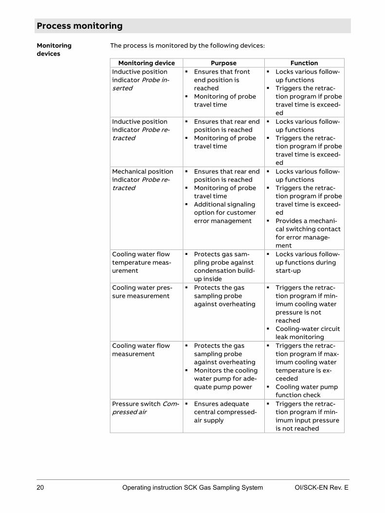
Process monitoring
The process is monitored by the following devices:
Monitoring device Purpose Function Inductive position indicator Probe in-serted
Ensures that front end position is reached
Monitoring of probe travel time
Locks various follow-up functions
Triggers the retrac-tion program if probe travel time is exceed-ed
Inductive position indicator Probe re-tracted
Ensures that rear end position is reached
Monitoring of probe travel time
Locks various follow-up functions
Triggers the retrac-tion program if probe travel time is exceed-ed
Mechanical position indicator Probe re-tracted
Ensures that rear end position is reached
Monitoring of probe travel time
Additional signaling option for customer error management
Locks various follow-up functions
Triggers the retrac-tion program if probe travel time is exceed-ed
Provides a mechani-cal switching contact for error manage-ment
Cooling water flow temperature meas-urement
Protects gas sam-pling probe against condensation build-up inside
Locks various follow-up functions during start-up
Cooling water pres-sure measurement
Protects the gas sampling probe against overheating
Triggers the retrac-tion program if min-imum cooling water pressure is not reached
Cooling-water circuit leak monitoring
Cooling water flow measurement
Protects the gas sampling probe against overheating
Monitors the cooling water pump for ade-quate pump power
Triggers the retrac-tion program if max-imum cooling water temperature is ex-ceeded
Cooling water pump function check
Pressure switch Com-pressed air
Ensures adequate central compressed-air supply
Triggers the retrac-tion program if min-imum input pressure is not reached
Monitoring devices

OI/SCK-EN Rev. E Operating instruction SCK Gas Sampling System 21
Monitoring device Purpose Function Cooling water return temperature meas-urement
Protects the probe against overheating
Triggers the retrac-tion program if max-imum temperature is exceeded
Locks follow-up functions
Pressure switch Emergency tank full (optional)
Ensures adequate compressed-air re-serve
Triggers the retrac-tion program if min-imum input pressure is not reached
Reed contact shutter open (only for auto-matic shutter actua-tion)
Protects the gas sampling probe against damage
Prevents insertion of the gas sampling probe if the shutter is not fully open
Sample gas line tem-perature measure-ment
Protects the sample gas line against con-densation build-up in-side
Prevents insertion of the gas sampling probe if the sample gas line is not fully heated up
Cable drag chain temperature meas-urement
Protects the cable drag chain against condensation build-up inside
Prevents insertion of the gas sampling probe if the sample gas line is not fully heated up
The following monitoring devices belong to the probe H only:
Monitoring device Purpose Function Reed contact plunger extended
Protects the plunger against overheating
Triggers the retrac-tion program if end position is not reached
Reed contact plunger retracted
Protects the plunger against overheating
Triggers the retrac-tion program if end position is not reached
Only for probe H

22 Operating instruction SCK Gas Sampling System OI/SCK-EN Rev. E
Controls and displays
The control cabinet is the central control point of the sampling system. The electric power supply and signals for the entire sampling system are connect-ed and distributed here. It is contains the display and operating unit for moni-toring and operating the system.
The control program is equipped with various locking mechanisms that pre-vent damage to the gas sampling probe due to incorrect operation or failure of individual modules. If not all locking conditions are met, operation is not possible. This safeguard is only overridden by personnel safety measures.
The picture shows controls on the control cabinet (side view left, front oper-ating panel right):
The controls and displays on the control cabinet have the following function:
No. Designation Function 1 Main switch Switches power supply on and off 2 Uninterruptible
power supply switch (optional)
Switches uninterruptible power supply on and off
3 Touchscreen Display and operating unit for monitoring the system; for operation see Description of the controller on page 35
4 Warning buzzer See Protective installations on page 59 5 Service switch Puts the system into service mode
Cancels service mode
There are additional controls and displays on the retractor:
Control cabinet
Controls on the control cabinet
Function of controls
Other controls

OI/SCK-EN Rev. E Operating instruction SCK Gas Sampling System 23
Designation and illus-tration
Function
EMERGENCY STOP switch on pneumatic box
see Protective installations on page 59
Warning lamps (2) on the terminal box
see Protective installations on page 59

24 Operating instruction SCK Gas Sampling System OI/SCK-EN Rev. E
Probe retractor
The probe retractor moves the up to 3.5 m long gas sampling probe. The drive is a pneumatic chain drive.
The following illustration shows the probe retractor:
The main components of the probe retractor are:
No. Component Function 1 Pneumatic box Central monitoring device to
control compressed-air supply 2 EMERGENCY-STOP switch Interrupts movement of the gas
sampling probe. 3 Pneumatic motor Ensures movement of the probe
retractor. 4 Terminal box Electric current connection.
5 Heated connection box ("cable drag chain")
Connection between the sample gas line of the gas sampling system and the downline sample gas line of the gas analysis sys-tem.
6 Shutter (with automatic [pneumat-ic] or manual actuation)
Closes the kiln duct opening when the probe is retracted.
not illustrated
Transport supports For safe transport / storage of the retractor (removed in opera-tion).
7 Gas sampling probe For sampling sample gas. 8 Heated sample gas line Transports the sample gas from
the probe to the downline sam-ple gas analysis system. Heating function prevents condensation from building up.
9 Warning lamps Warn about insertion and retrac-tion movements of the gas sam-pling probe.
10 Energy chain Guides pneumatic lines and electrical cables and the heated sample gas line and cooling water tubes.
Meaning
Structure
Function of components

OI/SCK-EN Rev. E Operating instruction SCK Gas Sampling System 25
No. Component Function 11 Probe cleaning unit Controls cleaning functions on
the sample gas probe.
The probe is automatically retracted if the following malfunctions occur:
Cooling water temperature too high Cooling water flow rate too low Cooling water pressure too low Circulation pump failure Power supply interrupted Compressed air failure
To protect the process against ambient air from being drawn in and to pro-tect operators, the duct opening is closed by a shutter when the probe is retracted. This does not apply, however, to regular retraction/extension for cleaning the outside of the probe.
The shutter is moved either automatically by a pneumatic drive or manually.
The pneumatic/electric supply is connected at a central transition point. All required line connections are pre-installed in the probe retractor.
Retraction in the event of malfunction
Shutter
Supply lines

26 Operating instruction SCK Gas Sampling System OI/SCK-EN Rev. E
Gas sampling probe H
The gas sampling probe H is used to sample the sample gas from the process.
The following illustration shows the gas sampling probe H:
The main components of the gas sampling probe H are:
No. Component Function 1 Gas tube Transports the sample gas through
the probe to the gas outlet. 2 Connection for air can-
non Compressed-air blast from air can-non breaks up material deposits between the probe and the wall tube.
3 Wall tube Pipe stub on rotary kiln. 4 Compressed air connec-
tion Allows periodical cleaning of the filter with compressed air.
5 Compressed-air cylinder Drives the plunger movement. 6 Gas outlet Passes the sample gas to the down-
line sample gas analysis system. 7 Bellows Flexible sealing component be-
tween the outer fixed part of the probe and the moving plunger part.
8 Cooling water connec-tions
Cooling water supply for probe cooling.
9 Mounting flange For fastening the gas sampling probe to the retractor.
10 Pipe sealing device Spring-mounted sealing of the wall tube.
11 Filter Initial filtering of the sample gas for dust removal.
12 Plunger Removes incrustations on the in-take opening.
13 Sample gas intake open-ing
Sucks in the sample gas in the rota-ry kiln.
Meaning
Structure
Function of components

OI/SCK-EN Rev. E Operating instruction SCK Gas Sampling System 27
Probe H is used when stubborn incrustations can be expected to build up on the probe due to the properties of the process and sampling conditions.
The two gas sampling probes H and 60S differ above all in the following:
Gas sampling probe H Gas sampling probe 60S
Cleaning procedure
Combined mechani-cal/pneumatic cleaning
Multi-stage pneumatic cleaning
Location of the filter element
Inner filter element Outer filter element
Sampling holes Front sampling hole Side sampling hole
Cleaning the gas sampling probe H comprises the following procedures:
Cleaning procedure Mode of functioning
Cleaning of the wall tube Compressed-air blast from air cannon removes material deposits between the probe and the wall tube.
Cleaning of the outside of the probe
Material deposits and incrustations on the probe are removed by regularly moving the probe in and out using the retractor.
Cleaning the probe intake hole by means of plunger movements
Incrustations on the intake hole are removed by periodical pneumatically controlled move-ments of the plunger.
Probe filter cleaning Filter in probe pipe is cleaned periodically with compressed air.
Differences
Cleaning

28 Operating instruction SCK Gas Sampling System OI/SCK-EN Rev. E
Gas sampling probe 60S
The gas sampling probe is used to sample the sample gas from the process.
The following illustration shows the gas sampling probe 60S:
The main components of the gas sampling probe 60S are:
No. Component Function 1 Sample gas intake holes Sucks in the sample gas in the kiln. 2 Gas tube Transports the sample gas
through the probe to the gas out-let.
3 Connection for air cannon Compressed-air blast from air cannon breaks up material depos-its between the probe and the wall tube.
4 Wall tube Pipe stub on rotary kiln. 5 Cooling water connec-
tions Cooling water supply for probe cooling.
6 Mounting flange For fastening the gas sampling probe to the retractor.
7 Filter unit FE2 Initial filtering of the sample gas for dust removal. 8 Ceramic filter
9 Compressed air connec-tions
Allows periodical cleaning of the filter with compressed air.
10 Protective case Filter unit casing. 11 Gas outlet Passes the sample gas to the
downline sample gas analysis system.
12 Heating sleeve Heats the filter unit to prevent condensation build-up.
13 Pipe sealing device Spring-mounted sealing of the tube
Meaning
Layout
Function of components

OI/SCK-EN Rev. E Operating instruction SCK Gas Sampling System 29
Probe 60S is used when stubborn incrustations are not expected to build up on the probe due to the properties of the process and sampling conditions.
The two water-cooled gas sampling probes H and 60S differ above all in the following:
Gas sampling probe H Gas sampling probe 60S
Cleaning proce-dure
Combined mechani-cal/pneumatic cleaning
Multi-stage pneumatic cleaning
Location of the filter element
Inner filter element Outer filter element
Sampling holes A front sampling hole Two side sampling holes
The gas sampling probe 60S offers the following cleaning procedures:
Cleaning procedure Mode of functioning
Cleaning of the wall tube Compressed-air blast from air cannon re-moves material deposits between the probe and the wall tube.
Cleaning of the outside of the probe
Material deposits and incrustations on the probe are removed by regularly moving the probe in and out using the retractor.
Probe filter cleaning Filter in filter unit is cleaned periodically with compressed air.
Differences
Cleaning

30 Operating instruction SCK Gas Sampling System OI/SCK-EN Rev. E
Cooling module
Owing to the prevailing operating conditions it is necessary to cool the gas sampling probe. The probe cooling system serves to provide and monitor the cooling water supply. In addition to the speed-controlled heat exchanger and cooling water transport unit, this unit also houses all transducers for monitor-ing cooling water. The completely closed system monitors the following pa-rameters:
Cooling water temperature Cooling water flow rate Cooling water pressure
The following illustrations show the cooling module:
Meaning
Structure

OI/SCK-EN Rev. E Operating instruction SCK Gas Sampling System 31
The main components of the cooling module are:
No. Component
1 Temperature sensor (return) -B55
2 Cooling water return (brass, pipe connector 1")
3 Check valve -J65
4 Shut-off valve cooling water -J63
5 Cooling water inlet (brass, pipe connector 1")
6 Cooling water feed (brass, pipe connector 1")
7 Pressure controller -B56
8 Temperature sensor (feed) -B54
9 Safety relief valve outlet (brass, pipe connector 1")
10 Safety relief valve cooling water pressure -J62
11 Surge tank -J61
12 Fan motor heat exchanger -M52
13 Heat exchanger -J60
14 Cooling water pump -M51
15 Winbloc analog input module -D51
16 Winbloc CAN bridge -D50
17 Terminal strip power supply for motor and pump -X51
18 Terminal box -W51
19 Cable glands and cable feed-through
20 Flow controller -B57
The closed cooling-water circuit must be filled with approx. 50 l potable water (requirements: see Preparing the cooling-water circuit on page 114). The cir-culation pump transports at least 5 m3/h through the probe pipe. The re-sistance thermometer is installed at the cooling water inlet of the cooling module and signals to the water temperature controller.
The water flows through the heat exchanger and pressure-compensating vessel. Additional instruments for measuring pressure, flow rate and temper-ature and fitted in the water pipe. Monitoring is performed on the touchscreen on the control cabinet.
Function of components
Cooling water circuit regulation

32 Operating instruction SCK Gas Sampling System OI/SCK-EN Rev. E
Transformer
The gas sampling system can be fitted with a three-phase dry transformer (see System identification on page 10). The three-phase dry transformer is located in a sheet metal casing with door and base, wiring is by means of threaded connections. The casing is dip-impregnated to protect against moisture.
Power 6900.00 VA UL
Primary voltage 3 x 208 V (delta)
Secondary voltage 3 x 400 V (star)
Degree of protection IP 54
Test voltage 4.0 kV
Insulation category T 50/A
Winding separate
Protection class I
Frequency 60 Hz
Switching YNd5
PRI-/SEC connection Terminals with screw connection
Transformer option
Characteristics/ Design features

OI/SCK-EN Rev. E Operating instruction SCK Gas Sampling System 33
Compressed-air tank and pneumatic system
The compressed-air system serves to retract the probe out of the rotary kiln in the event of malfunctions, e.g. power supply failure. The compressed air is also used to clean the probe for certain types of probe.
The compressed air must meet the following minimum requirements:
Dew point +3 °C
Pressure 6 bar (6000 hPa) positive pressure
Consumption approx. 3 m3/h
One probe travel (2 x 20 s) requires approx. 1 m3.
Other requirements are:
The compressed air must be free of dirt and oil/water droplets. At ambient temperatures below 0 °C make sure that the compressed-air
supply cannot freeze.
The sampling system can be fitted with a 250-l compressed-air tank. The compressed-air tank serves to back up probe movement if the on-site com-pressed-air supply fails.
This tank is not required if the on-site compressed-air supply is of stable performance.
Meaning
Requirements
Optional compressed-air tank


OI/SCK-EN Rev. E Operating instruction SCK Gas Sampling System 35
Chapter 3 Description of control system
Topic Page Structure and function of the control system ................................................ 36
User interface: Operation screen ...................................................................... 38
User interface: Trend screen ............................................................................. 40
User interface: Message screen......................................................................... 42
User interface: Parameter screen..................................................................... 44
Error message display .........................................................................................45
Access permissions ............................................................................................. 47
Default operating parameter settings ............................................................ 48
Optimizing operating parameters .................................................................... 51

36 Operating instruction SCK Gas Sampling System OI/SCK-EN Rev. E
Structure and function of the control system
The system is equipped with operating software operated from a touchscreen. It is located on the front of the control cabinet. The operator can select functions and configure settings from here. To select a function or configure settings, the operator simply touches the buttons with his finger.
The following diagram depicts the menu structure. Only the first two of a maximum of four menu levels are shown.
The following table outlines the functions of the main menus:
Menu Function
Operation Operating functions for start-up, maintenance, etc.
Diagnosis Displays current measured values, trend displays, messages and system information, etc.
Setup Setup for system optimization (limits, etc.), access permissions, editing tolerance ranges, network settings, etc.
Authentication is performed on the Login User screen, that the operator accesses in the Start menu by pressing the Menu button and then Login. Without user authorization, the operator can only access the dialogs in the Diagnosis menu. For an overview of access permissions in the various areas of the control system, please refer to the section on Access permission on page 47.
What is the control system for?
Structure
Functions
Login

OI/SCK-EN Rev. E Operating instruction SCK Gas Sampling System 37
The user navigates the interface in the bottom right corner of the screen. The Menu button goes back to the main menu, the Back button jumps to the previous menu. Press the Message button to view the logbook containing all error messages, etc.
The menus of the operating software may contain pop-up menus with user prompts. We distinguish the following modes of data entry:
Selection menus, e.g. to select a user name On/off buttons, e.g. to open and close the shutter Pop-up input panel (on-screen keyboard alphanumeric), e.g. to enter the
user name Pop-up input panel (on-screen keyboard numeric), e.g. to enter the pass-
word
The following list indicates the four basic screen types of the control system:
User interface: operating screen on page 38 User interface: trend screen on page 40 User interface: message screen on page 42 User interface: parameter screen on page 44
Navigation
Data entry
Screens

38 Operating instruction SCK Gas Sampling System OI/SCK-EN Rev. E
User interface: Operation screen
This is a typical operation screen:
The various areas of the screen have the following functions:
No. Designation Function
1 Mode Displays the mode (AUTOMATIC, MANUAL)
2 System status lights
Displays the current system status (normal operation, error, maintenance requirement, maintenance)
3 Display area Current menu display area
4 Current menu Menu path display
5 Screen functions Displays screen functions and submenus
6 Navigation area Allows the following functions: jump to Message menu jump to main menu jump to previous menu
Illustration
Screen areas

OI/SCK-EN Rev. E Operating instruction SCK Gas Sampling System 39
The following table lists the buttons and displays in the user interface and their functions:
Symbol Function
Displays the mode (AUTOMATIC or MANUAL)
System status lights: green: normal operation red: error orange: maintenance required blue: maintenance
Menu path display
Display box: white: requirement not met / process interrupted /
inactive green: requirement met black: follow-up function / process running / active
Progress bar: time to next cleaning (only enabled in cleaning menus)
Button to trigger a function associated with a control (button grayed-out if disabled)
Jump to previous menu
Jump to main menu
Display Message menu
Buttons and symbols

40 Operating instruction SCK Gas Sampling System OI/SCK-EN Rev. E
User interface: Trend screen
This is a typical trend screen:
The various areas of the screen have the following functions:
No. Designation Function
1 Measure val-ue/time (reading rule)
indicates the measured value at the time defined by the reading rule
2 Current measured value
Current measured value
3 Display area Displays measured values and alarm thresholds in the form of a line diagram
4 Navigation area Allows the following functions: jump to Message menu jump to main menu jump to previous menu
5 Save Saves trend data
6 Diagram navigation
Allows you to zoom in/out in the line dia-gram and move the window currently dis-played
Illustration
Screen areas

OI/SCK-EN Rev. E Operating instruction SCK Gas Sampling System 41
The following table lists the buttons and displays in the user interface and their functions:
Symbol Function
Move the reading rule left/right in the diagram
Jump to previous menu
Jump to main menu
Display Message menu
Save contents: Save diagram data in xls format
Move contents of window left/right
Zoom in/out
The following colors are used in the trend screen line diagram:
Color Meaning
blue Measured value
yellow Pre-alarm
red Main alarm
Buttons and symbols
Colors
42 Operating instruction SCK Gas Sampling System OI/SCK-EN Rev. E
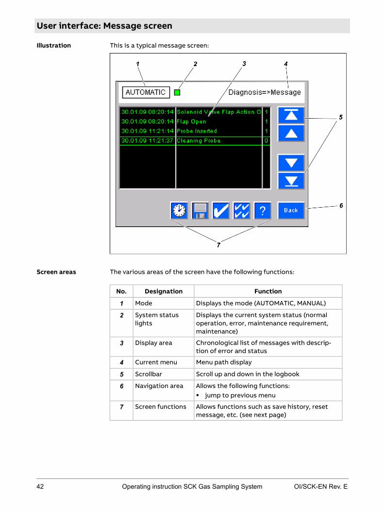
User interface: Message screen
This is a typical message screen:
The various areas of the screen have the following functions:
No. Designation Function
1 Mode Displays the mode (AUTOMATIC, MANUAL)
2 System status lights
Displays the current system status (normal operation, error, maintenance requirement, maintenance)
3 Display area Chronological list of messages with descrip-tion of error and status
4 Current menu Menu path display
5 Scrollbar Scroll up and down in the logbook
6 Navigation area Allows the following functions: jump to previous menu
7 Screen functions Allows functions such as save history, reset message, etc. (see next page)
Illustration
Screen areas

OI/SCK-EN Rev. E Operating instruction SCK Gas Sampling System 43
The following table lists the buttons and displays in the user interface and their functions:
Symbol Function
Displays the mode (AUTOMATIC or MANUAL)
System status lights: green: normal operation red: error orange: maintenance required blue: maintenance
Menu path display
Scroll buttons: scrolls logbook up/down and jumps to beginning/end
Jump to previous menu
Display help texts
Reset all messages
Reset the select message
Save contents: Save messages in xls format
Display all messages in chronological order
Click on crossed-out clock to display pending messages only
The following colors are used in the message screen display area:
Color Meaning
green Status message in normal operation
yellow Maintenance required
red Error message
Buttons and symbols
Colors
44 Operating instruction SCK Gas Sampling System OI/SCK-EN Rev. E
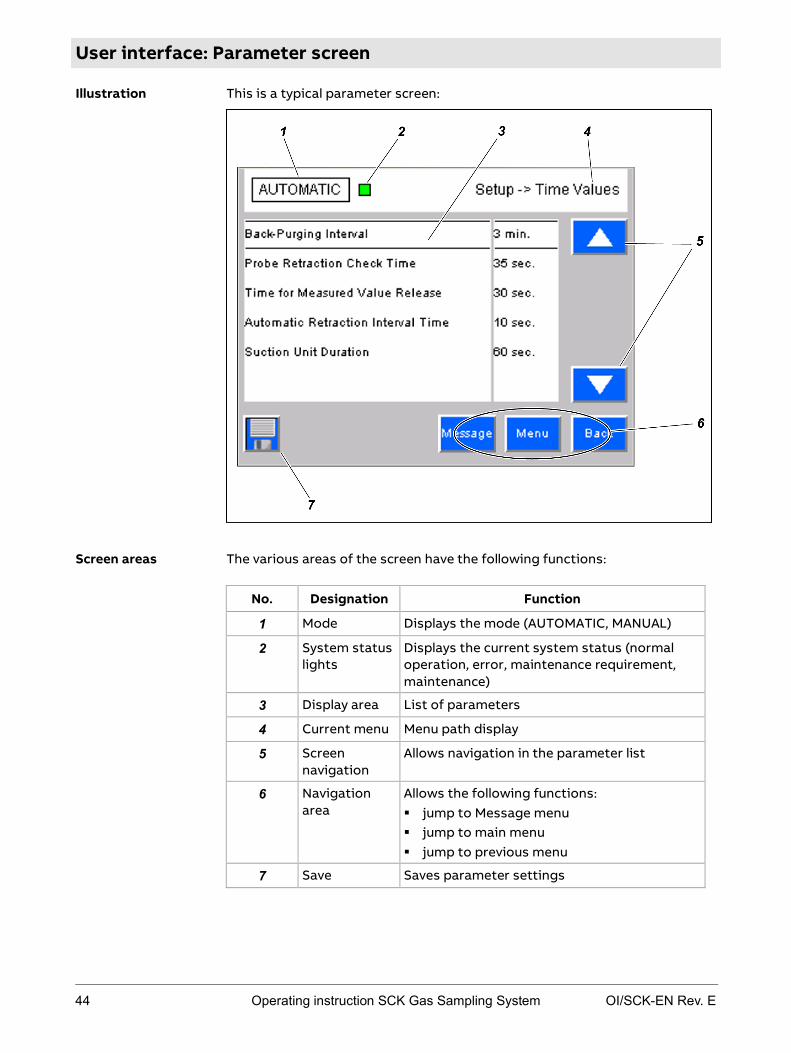
User interface: Parameter screen
This is a typical parameter screen:
The various areas of the screen have the following functions:
No. Designation Function
1 Mode Displays the mode (AUTOMATIC, MANUAL)
2 System status lights
Displays the current system status (normal operation, error, maintenance requirement, maintenance)
3 Display area List of parameters
4 Current menu Menu path display
5 Screen navigation
Allows navigation in the parameter list
6 Navigation area
Allows the following functions: jump to Message menu jump to main menu jump to previous menu
7 Save Saves parameter settings
Illustration
Screen areas
OI/SCK-EN Rev. E Operating instruction SCK Gas Sampling System 45
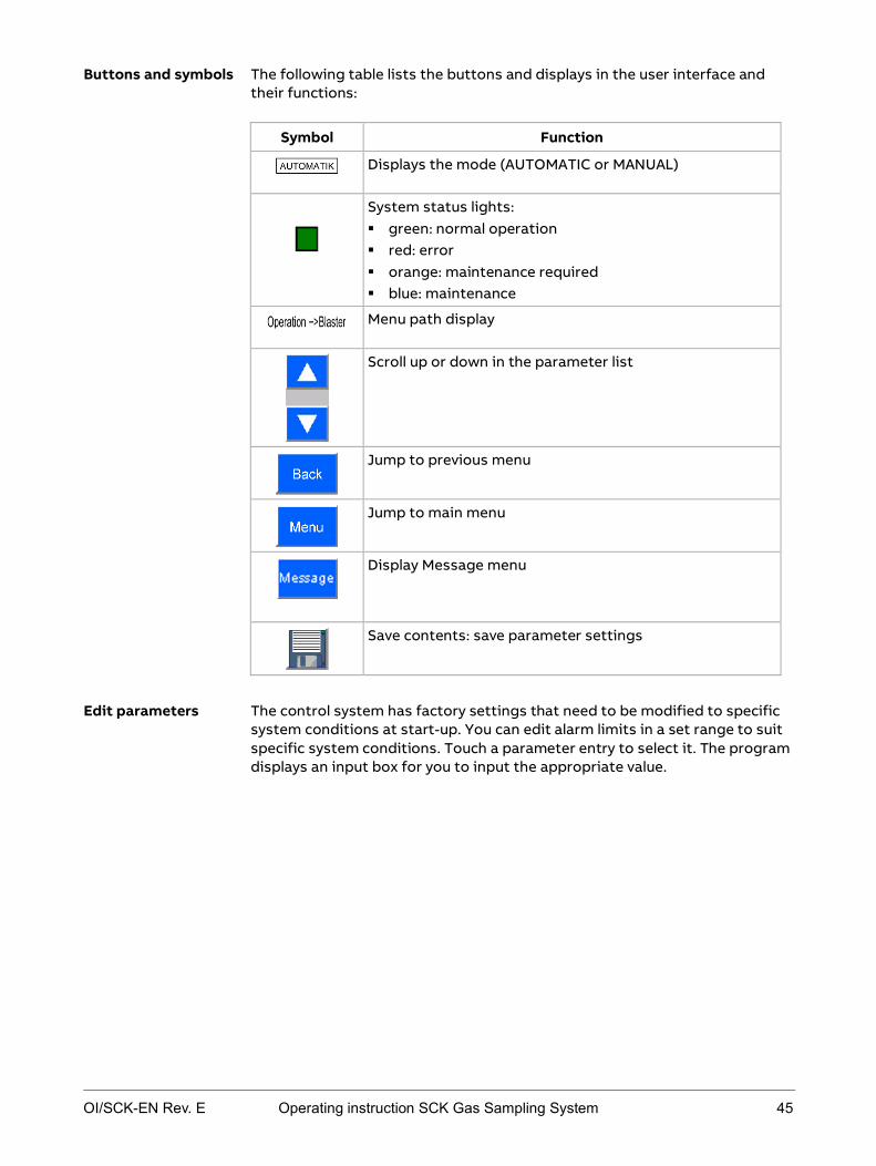
The following table lists the buttons and displays in the user interface and their functions:
Symbol Function
Displays the mode (AUTOMATIC or MANUAL)
System status lights: green: normal operation red: error orange: maintenance required blue: maintenance
Menu path display
Scroll up or down in the parameter list
Jump to previous menu
Jump to main menu
Display Message menu
Save contents: save parameter settings
The control system has factory settings that need to be modified to specific system conditions at start-up. You can edit alarm limits in a set range to suit specific system conditions. Touch a parameter entry to select it. The program displays an input box for you to input the appropriate value.
Buttons and symbols
Edit parameters

46 Operating instruction SCK Gas Sampling System OI/SCK-EN Rev. E
Error message display
Error messages are displayed on the touchscreen. All error messages are stored in the logbook (message screen). Touch the Message button on the interface to display this logbook. Refer to the section on Errors on page 215 for details on error messages and handling.
Error display

OI/SCK-EN Rev. E Operating instruction SCK Gas Sampling System 47
Access permissions
The system controller has several access levels. They are enabled by entering a password.
The password levels are divided as follows.
Level 1 Level 2 Level 3
Operation Operating function for daily mainte-nance
Operating function for start-up and pe-riodical mainte-nance
Allows checking of control and moni-toring functions
Diagnosis Displays cur-rent measured values, mes-sages
Trend displays of internal measured quantities
Logbook Reset messages Special system
information
Setup Setup for system optimization (limits, etc.)
Access permissions
Edit tolerance ranges
Network settings
A higher access level always includes the permissions of the lower access levels.
In level 3 you can configure parameters that may result in functional impair-ment of the system. Changes in these access areas may only be performed by experienced skilled personnel with ABB certification as level-2 service techni-cian. Always be extremely careful to whom you disclose the password for this level.
In the delivered state, the following passwords are stored in the system:
Level 1 1111
Level 2 2020
Level 3 only handed out after completing level-2 service technician training
Password entry
Hierarchy of access levels
Comment on password level 3
Password in delivered state

48 Operating instruction SCK Gas Sampling System OI/SCK-EN Rev. E
Default operating parameter settings
The control system has the following factory settings that need to be modi-fied to specific system conditions at start-up.
Parameter Default Back-Purging Interval
3 min
Probe Retraction Check Time
90 s
Time for Measured Value Release
100 s
Automatic Retraction Interval Time
30 s
Suction Unit Duration
60 s
Time parameters
OI/SCK-EN Rev. E Operating instruction SCK Gas Sampling System 49
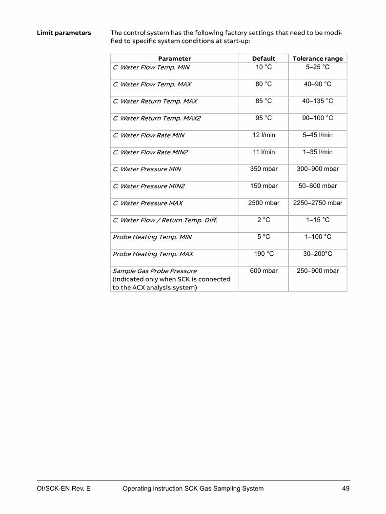
The control system has the following factory settings that need to be modi-fied to specific system conditions at start-up:
Parameter Default Tolerance range C. Water Flow Temp. MIN
10 °C 5–25 °C
C. Water Flow Temp. MAX
80 °C 40–90 °C
C. Water Return Temp. MAX
85 °C 40–135 °C
C. Water Return Temp. MAX2
95 °C 90–100 °C
C. Water Flow Rate MIN
12 l/min 5–45 l/min
C. Water Flow Rate MIN2
11 l/min 1–35 l/min
C. Water Pressure MIN
350 mbar 300–900 mbar
C. Water Pressure MIN2
150 mbar 50–600 mbar
C. Water Pressure MAX
2500 mbar 2250–2750 mbar
C. Water Flow / Return Temp. Diff.
2 °C 1–15 °C
Probe Heating Temp. MIN
5 °C 1–100 °C
Probe Heating Temp. MAX
190 °C 30–200°C
Sample Gas Probe Pressure (indicated only when SCK is connected to the ACX analysis system)
600 mbar 250–900 mbar
Limit parameters

50 Operating instruction SCK Gas Sampling System OI/SCK-EN Rev. E
The control system has the following factory settings that need to be modi-fied to specific system conditions at start-up:
Parameter Default Tolerance range Action / Cleaning Cycle Ratio
3
C. Water Return Temp. Set Point
80 °C 15–140 °C
Probe Heating Temp. Set Point
100 °C 1–190 °C
Basic parameters

OI/SCK-EN Rev. E Operating instruction SCK Gas Sampling System 51
Optimizing operating parameters
The control system has factory settings that need to be modified to specific system conditions at start-up. You can edit alarm limits in a set range to suit specific system conditions. Limited configuration serves to protect the probe retractor against harmful or contradictory settings. A list of operating pa-rameters with defaults can be found in Default operating parameter settings on page 48.
A password for a certain access level is required to edit parameters:
Level 1 Level 2 Level 3 Edit time values X X Edit limits X X Edit basic values X X
Proceed as follows to edit a time parameter:
Step Procedure 1 Open the Time Values parameter screen.
Path: Setup ► Time Parameters 2 Select parameter and enter appropriate value in the input box.
Note: You can only edit time values within the tolerance limits. 3 Click the Save button to save the settings.
Proceed as follows to edit a limit parameter:
Step Procedure 1 Open the Alarm Values parameter screen.
Path: Setup ► Limit Parameters 2 Select parameter and enter appropriate value in the input box.
Note: You can only edit limits within the tolerance limits.
3 Click the Save button to save the settings.
Proceed as follows to edit a basic parameter:
Step Procedure 1 Open the Basic Values parameter screen.
Path: Setup ► Basic Parameters 2 Select parameter and enter appropriate value in the input box.
Note: You can only edit basic values within the tolerance limits. 3 Click the Save button to save the settings.
Introduction
Access levels
Edit time values
Edit limit values
Edit basic values

OI/SCK-EN Rev. E Operating instruction SCK Gas Sampling System 53
Chapter 4 Safety
Topic Page Basic safety rules .................................................................................................54
Overview of dangers ............................................................................................ 57
Protective installations ....................................................................................... 59
Warning signs on the system ............................................................................. 63
Requirements to be met by personnel, work places .................................... 64
Personal safety equipment ................................................................................ 67
Safety measures: Transport and unpacking ...................................................68
Safety measures: Installation ............................................................................69
Safety measures: Start-up .................................................................................. 72
Safety measures: Operation .............................................................................. 76
Safety measures: Maintenance and troubleshooting .................................. 80

54 Operating instruction SCK Gas Sampling System OI/SCK-EN Rev. E
Basic safety rules
These rules are intended for all persons handling the gas sampling system.
The purpose of these rules is to ensure that all persons handling the gas sam-pling system are thoroughly informed about risks and safety measures and that they observe the safety instructions in the operating instructions and on the system. Failing to observe these rules can lead to a risk of damage to property, injuries or even death.
Observe the following rules:
Completely read through the Safety section and the sections pertaining to your work. You must have understood these sections.
Always keep the operating instructions handy nearby the gas sampling system for reference.
Pass on the operating instructions if the gas sampling system is re-sold.
Observe the following rules:
Only persons fulfilling the requirements specified in these operating in-structions may handle the gas sampling system.
The gas sampling system may only be used for the intended purpose. Never use the gas sampling system for any other purposes, even if they appear reasonable.
Take all safety measures specified in these operating instructions and on the system. Specifically, use the prescribed personal safety equipment.
Only work in the designated work areas. Do not make any modifications to the gas sampling system, e.g. by remov-
ing parts or attaching non-approved parts. Specifically, do not change or disable any protective installations.
Use only original spare parts when replacing defective components. The gas sampling system may only be operated if maintenance work is
performed regularly and expertly.
Target group for these rules
Purpose of these rules
Handling the operating instructions
Handling the gas sampling system

OI/SCK-EN Rev. E Operating instruction SCK Gas Sampling System 55
The operator must ensure
that personnel meets the requirements for their tasks. that personnel is provided with the personal safety equipment specified in
these operating instructions and, if necessary, additional safety equip-ment against risks posed by the installation site, e.g. by noise.
that personnel is provided with maintenance equipment in order to secure the service switch, e.g. padlocks.
that the system has protection against restarting the power supply in order to ensure that the system is powered off when the main switch is switched off.
to prevent unauthorized activation of the power supply. that personnel have read and understood these operating instructions
before they handle the gas sampling system. that personnel is regularly and recurrently instructed about the risks and
safety measures when handling the gas sampling system. that the work areas of the gas sampling system are adequately aired and
illuminated. that the safety regulations in force in your country are observed. that the safety regulations pertaining to setting up and operating electri-
cal equipment in force in your country are observed. that the safety regulations pertaining to handing gases, lubricants, etc. in
force in your country are observed.
The gas sampling system is designed and built in such a way that personnel can work with it without any risk. Despite all precautions, however, unfore-seeable accidents may nevertheless occur in unfavorable circumstances. If cooling water pipes or compressed-air pipes burst, shut down the gas sam-pling system and secure it against being switched on again. If errors are de-tected, shut down the system and secure it against being switched on again. Before approaching the gas sampling system, wait until the entire cooling water or the entire compressed air has been evacuated.
If the switched-on gas sampling system poses a danger, proceed as follows:
Aim Action Stop movement of the sys-tem
Press the EMERGENCY-STOP switch Note: The gas sampling probe interrupts its movement immediately and in any position. The probe is only retracted out of the rotary kiln after pressing the service switch.
Disconnect the system from the mains
Turn off the main switch
Evacuate the compressed-air system
Close the stop valve in the pneumatic box
Operator's obligations towards personnel
Procedure in the event of accidents

56 Operating instruction SCK Gas Sampling System OI/SCK-EN Rev. E
If it can be assumed that safe operation is no longer possible, the gas sam-pling system must be taken out of operation and secured against being start-ed up again.
It can be assumed that safe operation is no longer possible:
if the gas sampling system is visibly seriously damaged, If the gas sampling system no longer works, after prolonged storage under adverse conditions, after severe transport stress.
Intended Conditions of Use on page 17
Overview of dangers on page 57
Requirements to be met by personnel, work places on page 64
Personal safety equipment on page 67
Protective installations on page 59
Safety measures: transport and unpacking on page 68
Safety measures: installation on page 69
Safety measures: start-up on page 72
Safety measures: operation on page 76
Safety measures: maintenance and troubleshooting on page 80
If risk-free operation is no longer possible
Further information

OI/SCK-EN Rev. E Operating instruction SCK Gas Sampling System 57
Overview of dangers
The gas sampling system is designed such that the operator is protected against all dangers that can be reasonably avoided by means of design.
Due to the purpose of the gas sampling system, however, there are neverthe-less residual risks that require precautions to be avoided.
The following section gives information about the nature of these residual risks and their effect.
The gas sampling probe moves in and out automatically. Expect a system-actuated movement of the gas sampling probe at any time. The gas sampling probe not only performs individual extension and retraction movements but also performs combined processes involving successive extension and retrac-tion movements. This means:
risk of injury due to automatic extension and retraction movements of the gas sampling probe if anyone is standing in the retractor's area of travel.
danger of toxic, harmful gases when the shutter is open.
The gas sampling system contains current-carrying components. This means:
The main terminals -X30, -X40 and the input terminals of the main switch-es -Q30, -Q40 are live even when the main switches are off.
All metallic parts in the environment that can be touched at the same time as the machine must also be grounded together.
Check pre-protection according to the documentation. Danger of electrocution, If covers on control cabinet, terminal box or power connection are open.
Connectors in the control cabinet or terminal box may also carry cur-rent.
If the connection between the protective earth connector and a protec-tive earth conductor is not made before all other connections.
If the protective earth conductor is interrupted inside or outside the gas sampling system or the protective earth connector is disconnected.
If the set operating voltage and mains voltage do not match before switching on.
If work is performed on the open gas sampling system without discon-necting the gas sampling system from the power supply.
Due to charged capacitors in the gas sampling system even if the gas sampling system has been disconnected from all sources of power.
Due to fuses that do not match the specified type and nominal current and repaired fuses.
During operation of the gas sampling system surfaces and parts get hot. This means:
Danger of burning due to hot surfaces during and after operation of the system.
Meaning
Moving gas sampling probe
Current-carrying components
Hot surfaces

58 Operating instruction SCK Gas Sampling System OI/SCK-EN Rev. E
When the shutter is open, gases flow out of the rotary kiln duct opening that may be harmful to health. This means:
Danger of poisoning due to harmful gases. Danger of burning due to jets of flame at the duct opening.
During operation of the gas sampling system, the cooling water in the cooling system gets very hot. This means:
Danger of scalding in the event of contact with the hot cooling water. Danger of burning in the event of contact with the cooling water pipes.
The cooling system contains cooling water with anti-freeze. This means:
Danger of injury to skin and eyes in the event of contact with anti-freeze.
There may be lubricating oil in the pneumatic box, on the pneumatic motor filter muffler, and inside the pneumatic motor. This means:
Danger of injury to skin and eyes in the event of contact with lubricating oil.
The pneumatic system contains compressed air. This means
Danger of eye injuries if compressed air escapes, e.g. if compressed-air pipes burst, when opening screw connections or inadvertently opening compressed-air pipes with no additional connector.
Harmful gases at the duct opening
Hot cooling water
Anti-freeze in the cooling water
Lubricating oil in the pneumatic module
Compressed air in the pneumatic system

OI/SCK-EN Rev. E Operating instruction SCK Gas Sampling System 59
Protective installations
The gas sampling system is fitted with protective installations to protect the operator. All protective installations must be in place and operational during operation. The protective installations must not be disabled and must be checked for proper functioning at regular intervals.
The illustrations show the location of the protective installations on the gas sampling system.
Front view of the gas sampling system:
Top view of the rotary kiln with installed gas sampling probe and the danger zone around the probe retractor, which is secured by a protective installation (6).
Meaning
Illustration
6

60 Operating instruction SCK Gas Sampling System OI/SCK-EN Rev. E
The protective installations have the following function:
No. Designation and photo
Location Function
1 EMERGENCY-STOP switch
Pneumatic box of the retractor
Interrupts movement of the gas sampling probe. The gas sampling probe can only move again when the EMERGENCY-STOP switch is unlocked and reset by pressing the service switch.
2 Covers Retractor Cooling
module: ro-tor
Cooling module: Terminal box for elec-trical con-nections
Protection from inserting hand into the system.
3 Warning lamps
Retractor ter-minal box
Warn about probe move-ment. The warning lamps flash in the following situa-tions: Automatic mode: ap-
prox. 20 seconds be-fore probe movement
Manual mode: immedi-ately after pressing the "Retract probe" button
Error: immediately before probe retrac-tion
Protective installations
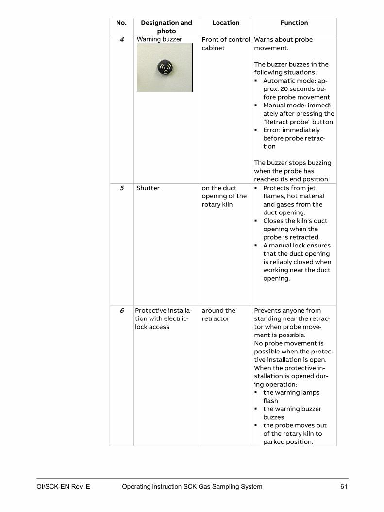
OI/SCK-EN Rev. E Operating instruction SCK Gas Sampling System 61
No. Designation and photo
Location Function
4 Warning buzzer
Front of control cabinet
Warns about probe movement. The buzzer buzzes in the following situations: Automatic mode: ap-
prox. 20 seconds be-fore probe movement
Manual mode: immedi-ately after pressing the "Retract probe" button
Error: immediately before probe retrac-tion
The buzzer stops buzzing when the probe has reached its end position.
5 Shutter on the duct opening of the rotary kiln
Protects from jet flames, hot material and gases from the duct opening.
Closes the kiln's duct opening when the probe is retracted.
A manual lock ensures that the duct opening is reliably closed when working near the duct opening.
6 Protective installa-tion with electric-lock access
around the retractor
Prevents anyone from standing near the retrac-tor when probe move-ment is possible. No probe movement is possible when the protec-tive installation is open. When the protective in-stallation is opened dur-ing operation: the warning lamps
flash the warning buzzer
buzzes the probe moves out
of the rotary kiln to parked position.

62 Operating instruction SCK Gas Sampling System OI/SCK-EN Rev. E
A warning horn additionally installed by the operator has the same function as the enclosed warning buzzer described above. The additional warning horn must be installed if you cannot hear the warning buzzer properly due to ambi-ent noise.
An EMERGENCY-STOP switch additionally installed by the operator has the same function as the enclosed EMERGENCY-STOP switch described above. The additional EMERGENCY-STOP switch must be installed if the above-described EMERGENCY-STOP switch is difficult to access.
Additional warning horn
Additional EMERGENCY-STOP switch

OI/SCK-EN Rev. E Operating instruction SCK Gas Sampling System 63
Warning signs on the system
Warning signs on the gas sampling probe warn about danger areas. The warn-ing signs must always be in place and easy to see.
The following illustration shows the location of the warning signs on the individual modules:
The warning signs on the control cabinet (1) have the following meaning:
Warning sign Meaning
Warns about current-carrying parts
There is a risk of electrocution by current-carrying parts in the area of the terminal bar for normal mains supply and the terminal bar for the UPS. This also applies when the main switch is turned off.
The warning signs on the cooling module (2) have the following meaning:
Warning sign Meaning
Warns about hot surfaces
A risk of hot surfaces can be expected during operation. Particular danger areas are: all cooling water pipes and the cooling water pump and the surface of the heat ex-changer.
Meaning of the warning signs
Illustration
Warning signs on the control cabinet
Warning signs on the cooling module

64 Operating instruction SCK Gas Sampling System OI/SCK-EN Rev. E
The warning signs on the retractor (3) have the following meaning:
Warning sign Meaning
Warns about hot surfaces
A risk of hot surfaces can be expected during operation. Particular danger areas are: all cooling water pipes, the heated sample gas line, the connection box for the heat-ed sample gas line on the probe retractor, the heated sampling filter, the entire gas sampling probe, the metal structure of the probe retractor (particularly in the area of the mounting flange), the shutter on the duct opening.
Warns about probe movements
Retractor movement can be expected during operation. Do not stand in the area of travel of the probe or probe carriage until the probe is completely inserted or retract-ed and the warning lamps go out.
Warning signs on the retractor

OI/SCK-EN Rev. E Operating instruction SCK Gas Sampling System 65
Requirements to be met by personnel, work places
Personnel handling the gas sampling system must meet the following re-quirements:
Personnel Tasks Required qualification
Transporter Transport in the company
Unpacking of the system
Trained crane operator/fork-lift driver
Experience with lifting appa-ratus
Mechanical fitter
mechanical installation mechanical disassembly
Mechanical expert
Electrical fitter
electrical installation electrical disassembly
Electrical expert
Start-up personnel
Initial start-up Putting back into oper-
ation
Technician familiar with the processes
of cement production and specific works conditions
Operator Operation Trained unskilled worker
Mechanical maintenance personnel
on mechanical parts: Maintenance Troubleshooting Maintenance Shutting down
Mechanical expert
Electrical maintenance personnel
on electric parts: Maintenance Troubleshooting Maintenance Shutting down
Electrical expert Experience with controllers
Storage personnel
correct storage packing of the system
for transport
Trained unskilled worker
Disposal personnel
Disposal of the gas sam-pling system
Trained disposal personnel
Personnel qualifications

66 Operating instruction SCK Gas Sampling System OI/SCK-EN Rev. E
In order to ensure safe handling of the gas sampling system, personnel must work in certain work places designated for their activity.
The work places for the various activities are located in the following places:
Activity Work places
Installation
Start-up
Maintenance
Shutting down
at the various modules of the gas sam-pling system, depending on the task
Operation depending on the particular task at the control cabinet to operate the
software around the gas sampling system to
monitor operation, but NOT in the danger area around the retractor that is protected by the protective installation.
Work places

OI/SCK-EN Rev. E Operating instruction SCK Gas Sampling System 67
Personal safety equipment
The following general protective equipment must be worn when performing any work in the area of the gas sampling system:
Closed overalls with long trousers and long sleeves Safety shoes Safety gloves suitable for mechanical work Safety glasses Protective helmet If necessary, additional protective equipment if prescribed by the opera-
tor.
The following additional protective equipment is required when performing maintenance work:
Dust mask Face mask against heat Heat-proof gloves and protective welder's clothing Respiratory protection against toxic gases from the rotary kiln
General protective equipment
Additional protective equipment

68 Operating instruction SCK Gas Sampling System OI/SCK-EN Rev. E
Safety measures: Transport and unpacking
This section contains a summary of possible dangers during transport and unpacking of the gas sampling system and measures designed to prevent physical injuries.
Observe the following dangers and take the specified preventive action when transporting and unpacking:
Danger Where / in what situa-tion does the danger
arise?
Preventive action
Mechanical and material dangers due to moving or falling parts, anti-freeze, lubricating oil
During all work on the gas sampling system and in the vicinity of the gas sampling sys-tem
Wear general personal pro-tective equipment: Closed overalls with long
trousers and long sleeves Safety shoes Safety gloves suitable for
mechanical work Safety glasses Protective helmet If necessary, additional
protective equipment if prescribed by the opera-tor.
Risk of crushing by heavy transport units
When lifting or lower-ing transport units
Only appropriately trained personnel may transport the transport units and only with the aid of the recommended transport equipment.
Do not stand under sus-pended loads.
Follow the transport instructions in these op-erating instructions care-fully.
Meaning
Dangers and preventive action
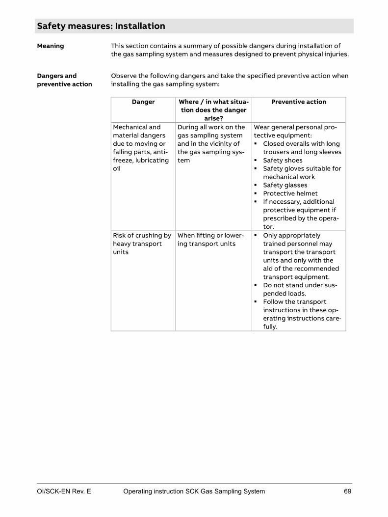
OI/SCK-EN Rev. E Operating instruction SCK Gas Sampling System 69
Safety measures: Installation
This section contains a summary of possible dangers during installation of the gas sampling system and measures designed to prevent physical injuries.
Observe the following dangers and take the specified preventive action when installing the gas sampling system:
Danger Where / in what situa-tion does the danger
arise?
Preventive action
Mechanical and material dangers due to moving or falling parts, anti-freeze, lubricating oil
During all work on the gas sampling system and in the vicinity of the gas sampling sys-tem
Wear general personal pro-tective equipment: Closed overalls with long
trousers and long sleeves Safety shoes Safety gloves suitable for
mechanical work Safety glasses Protective helmet If necessary, additional
protective equipment if prescribed by the opera-tor.
Risk of crushing by heavy transport units
When lifting or lower-ing transport units
Only appropriately trained personnel may transport the transport units and only with the aid of the recommended transport equipment.
Do not stand under sus-pended loads.
Follow the transport instructions in these op-erating instructions care-fully.
Meaning
Dangers and preventive action

70 Operating instruction SCK Gas Sampling System OI/SCK-EN Rev. E
Danger Where / in what situa-tion does the danger
arise?
Preventive action
Danger due to current-carrying parts
When working on elec-tric components
Only specialized electrical personnel may work on the electric system.
Disconnect the gas sam-pling system from the power supply before opening the connection and terminal box.
Observe national regula-tions pertaining to elec-trical equipment.
The main terminals -X30, -X40 and the input termi-nals of the main switches -Q30, -Q40 are live even when the main switches are off.
All metallic parts in the environment that can be touched at the same time as the machine must also be grounded together.
Check pre-protection according to the docu-mentation.
Risk of burning due to hot surfaces, hot gases, jet flames
At the duct opening when installing the probe in the rotary kiln
Preferably install the probe when the rotary kiln is out of operation.
If you install the probe when the rotary kiln is in opera-tion: Wear a face mask against
heat, heat-proof gloves and protective welder's clothing and respiratory protection against toxic gases.
Keep the time in which the duct opening is open as short as possible.

OI/SCK-EN Rev. E Operating instruction SCK Gas Sampling System 71
Danger Where / in what situa-tion does the danger
arise?
Preventive action
Danger due to harmful gases
Due to gases escaping from the duct opening of the rotary kiln
Only enter the danger area around the retractor when the shutter is closed.
Lock the shutter before commencing work.
Ensure adequate ventila-tion of the work place.
If work is unavoidable in the area of the duct open-ing, wear respiratory pro-tection in addition to the general protective equipment.
Danger due to harmful anti-freeze
In the cooling water of the cooling system
Avoid contact with the cooling water and the an-ti-freeze.
Wash any cooling water or anti-freeze off the skin immediately with water and soap.
If cooling water or anti-freeze gets in the eyes despite protective glass-es, rinse them thoroughly under running water, holding the eyelids open.
Observe instructions in the anti-freeze manufac-turer's safety data sheet.
Danger due to harmful lubricating oil
In the pneumatic box, on the pneumatic motor filter muffler, inside the pneumatic motor.
Avoid contact with lubri-cating oil.
Wash any lubricating oil off the skin immediately with water and soap.
If any lubricating oil gets in the eyes despite pro-tective glasses, rinse them thoroughly under running water, holding the eyelids open.
Observe instructions in the lubricating oil manu-facturer's safety data sheet.

72 Operating instruction SCK Gas Sampling System OI/SCK-EN Rev. E
Safety measures: Start-up
This section contains a summary of possible dangers during start-up of the gas sampling system and measures designed to prevent physical injuries.
Observe the following dangers and take the specified preventive action when starting-up the gas sampling system:
Danger Where / in what situa-tion does the danger
arise?
Preventive action
Mechanical, ther-mal and material dangers due to moving or falling parts, hot surfaces, hot cooling water, anti-freeze, com-pressed air, lubri-cating oil
During all work on the gas sampling system and in the vicinity of the gas sampling sys-tem
Wear general personal pro-tective equipment: Closed overalls with long
trousers and long sleeves Safety shoes Safety gloves suitable for
mechanical work Safety glasses Protective helmet If necessary, additional
protective equipment if prescribed by the opera-tor.
Risk of crushing due to moving gas sampling probe
In the travel area of the retractor when the probe moves in or out. This is the case in the following situations: at unforeseeable
times during auto-matic mode
in the event of the following errors in automatic mode:
failure or interrup-tion of the power supply
failure of the com-pressed-air supply
failure of the control system
when manually starting probe trav-el
when actuating the service switch
when opening the protective installa-tion securing the danger area around the retractor
Do not enter the danger area around the probe re-tractor until it is at stand-still and the warning lamps and buzzer are off.
Never stand in the danger area around the probe re-tractor when the protec-tive installation is closed.
When the warning lamps light up or the earning buzzer buzzes, leave the danger area around the probe retractor immedi-ately as the probe is about to move at any moment.
Press the EMERGENCY STOP switch immediately if anyone is still in the danger area around the retractor after the warn-ing lamps light up or the warning buzzer buzzes.
Meaning
Dangers and preventive action

OI/SCK-EN Rev. E Operating instruction SCK Gas Sampling System 73
Danger Where / in what situa-tion does the danger
arise?
Preventive action
Danger due to current-carrying parts
When working on elec-tric components
Only specialized electrical personnel may work on the electric system.
Disconnect the gas sam-pling system from the power supply before opening the connection and terminal box.
Observe national regula-tions pertaining to elec-trical equipment.
The main terminals -X30, -X40 and the input termi-nals of the main switches -Q30, -Q40 are live even when the main switches are off.
All metallic parts in the environment that can be touched at the same time as the machine must also be grounded together.
Check pre-protection according to the docu-mentation.
Risk of burning due to hot surfaces
The following compo-nents are very hot during and after opera-tion of the gas sam-pling system: the cooling module the heated sample
gas lines the connection box
for the heated sam-ple gas line on the retractor
the heated sam-pling filter
the entire gas sam-pling probe
the metal structure of the retractor
the shutter of the duct opening
Do not touch these com-ponents during and after operation.
Do not touch these com-ponents until they have cooled down to less than 50 °C.
If it is unavoidable to touch hot components, wear a face mask against heat, heat-proof gloves and protective welder's clothing.

74 Operating instruction SCK Gas Sampling System OI/SCK-EN Rev. E
Danger Where / in what situa-tion does the danger
arise?
Preventive action
Risk of burning due to falling or spall-ing material.
After the probe moves out of the rotary kiln, hot material may fall or spall off the probe.
Never enter the danger area around the retractor during operation.
Do not approach the retracted probe until it has cooled down.
If it is unavoidable to approach the hot probe, wear a face mask against heat, heat-proof gloves and protective welder's clothing.
Danger due to harmful gases, jet flames
Due to gases escaping from the duct opening of the rotary kiln
Only enter the danger area around the retractor when the shutter is closed.
Lock the shutter before commencing work.
Ensure adequate ventila-tion of the work place.
If work is unavoidable in the area of the duct open-ing, wear respiratory pro-tection in addition to the general protective equipment.
Risk of scalding due to hot cooling water
When working on the cooling water system, particularly: ventilation open-
ings Screw connections
Do not perform work on the cooling water system until it has cooled down.
Danger due to harmful anti-freeze
In the cooling water of the cooling system
Avoid contact with the cooling water and the an-ti-freeze.
Wash any cooling water or anti-freeze off the skin immediately with water and soap.
If cooling water or anti-freeze gets in the eyes despite protective glass-es, rinse them thoroughly under running water, holding the eyelids open.
Observe instructions in the anti-freeze manufac-turer's safety data sheet.

OI/SCK-EN Rev. E Operating instruction SCK Gas Sampling System 75
Danger Where / in what situa-tion does the danger
arise?
Preventive action
Danger due to harmful lubricating oil
In the pneumatic box, on the pneumatic motor filter muffler, inside the pneumatic motor.
Avoid contact with lubri-cating oil.
Wash any lubricating oil off the skin immediately with water and soap.
If any lubricating oil gets in the eyes despite pro-tective glasses, rinse them thoroughly under running water, holding the eyelids open.
Observe instructions in the lubricating oil manu-facturer's safety data sheet.
Risk of slipping Around the gas sam-pling system due to cooling water or lubri-cating oil that escapes or is spilled.
Always keep the floor around the gas sampling system clean and dry.

76 Operating instruction SCK Gas Sampling System OI/SCK-EN Rev. E
Safety measures: Operation
This section contains a summary of possible dangers during operation of the gas sampling system and measures designed to prevent physical injuries.
Observe the following dangers and take the specified preventive action when operating the gas sampling system:
Danger Where / in what situa-tion does the danger
arise?
Preventive action
Mechanical, ther-mal and material dangers due to moving or falling parts, hot surfaces, hot cooling water, anti-freeze, com-pressed air, lubri-cating oil
During all work on the gas sampling system and in the vicinity of the gas sampling sys-tem
Wear general personal pro-tective equipment: Closed overalls with long
trousers and long sleeves Safety shoes Safety gloves suitable for
mechanical work Safety glasses Protective helmet If necessary, additional
protective equipment if prescribed by the opera-tor.
Risk of crushing due to moving gas sampling probe
In the travel area of the retractor when the probe moves in or out. This is the case in the following situations: at unforeseeable
times during auto-matic mode
in the event of the following errors in automatic mode:
failure or interrup-tion of the power supply
failure of the com-pressed-air supply
failure of the control system
when manually starting probe trav-el
when actuating the service switch
when opening the protective installa-tion securing the danger area around the retractor
Never enter the danger area around the retractor during operation.
Press the EMERGENCY-STOP switch immediately if anyone is in the danger area around the retractor after the warning lamps light up or the warning buzzer buzzes.
Meaning
Dangers and preventive action

OI/SCK-EN Rev. E Operating instruction SCK Gas Sampling System 77
Danger Where / in what situa-tion does the danger
arise?
Preventive action
Danger due to current-carrying parts
Electric components in general, above all dam-aged electric compo-nents
If you are not specialized electrical personnel: Never open electric
components. Never touch damaged
electric components, cables or the inside of electric components.
Only specialized electrical personnel may work on the electrical system.
The main terminals -X30, -X40 and the input termi-nals of the main switches -Q30, -Q40 are live even when the main switches are off.
All metallic parts in the environment that can be touched at the same time as the machine must also be grounded together.
Check pre-protection according to the docu-mentation.
Risk of burning due to hot surfaces
The following compo-nents are very hot during and after opera-tion of the gas sam-pling system: the cooling module the heated sample
gas lines the connection box
for the heated sam-ple gas line on the retractor
the heated sam-pling filter
the entire gas sam-pling probe
the metal structure of the retractor
the shutter of the duct opening
Never enter the danger area around the retractor during operation.
Do not touch these com-ponents during and after operation.
If it is unavoidable to touch hot components, wear a face mask against heat, heat-proof gloves and protective welder's clothing.

78 Operating instruction SCK Gas Sampling System OI/SCK-EN Rev. E
Danger Where / in what situa-tion does the danger
arise?
Preventive action
Risk of burning due to falling or spall-ing material.
After the probe moves out of the rotary kiln, hot material may fall or spall off the probe.
Never enter the danger area around the retractor during operation.
Do not approach the retracted probe until it has cooled down.
If it is unavoidable to approach the hot probe, wear a face mask against heat, heat-proof gloves and protective welder's clothing.
Danger due to harmful gases, jet flames
If gases escape from the duct opening on the rotary kiln when the shutter is open during operation.
Never enter the danger area around the retractor during operation.
Ensure adequate ventila-tion of the work place.
Risk due to hot cooling water
In the event of hot cooling water escaping if an error occurs
Wait until the entire cool-ing water has been evac-uated before approach-ing.
Danger due to harmful anti-freeze
Cooling water escap-ing from the cooling system in the event of an error
Avoid contact with the cooling water and the an-ti-freeze.
Wash any cooling water or anti-freeze off the skin immediately with water and soap.
If cooling water or anti-freeze gets in the eyes despite protective glass-es, rinse them thoroughly under running water, holding the eyelids open.
Observe instructions in the anti-freeze manufac-turer's safety data sheet.
Danger due to harmful lubricating oil
Lubricating oil escap-ing from the pneumat-ic module in the event of an error
Avoid contact with lubri-cating oil.
Wash any lubricating oil off the skin immediately with water and soap.
If any lubricating oil gets in the eyes despite pro-tective glasses, rinse them thoroughly under running water, holding the eyelids open.
Observe instructions in the lubricating oil manu-facturer's safety data sheet.

OI/SCK-EN Rev. E Operating instruction SCK Gas Sampling System 79
Danger Where / in what situa-tion does the danger
arise?
Preventive action
Risk of slipping Around the gas sam-pling system due to cooling water or lubri-cating oil that escapes or is spilled.
Always keep the floor around the gas sampling system clean and dry.
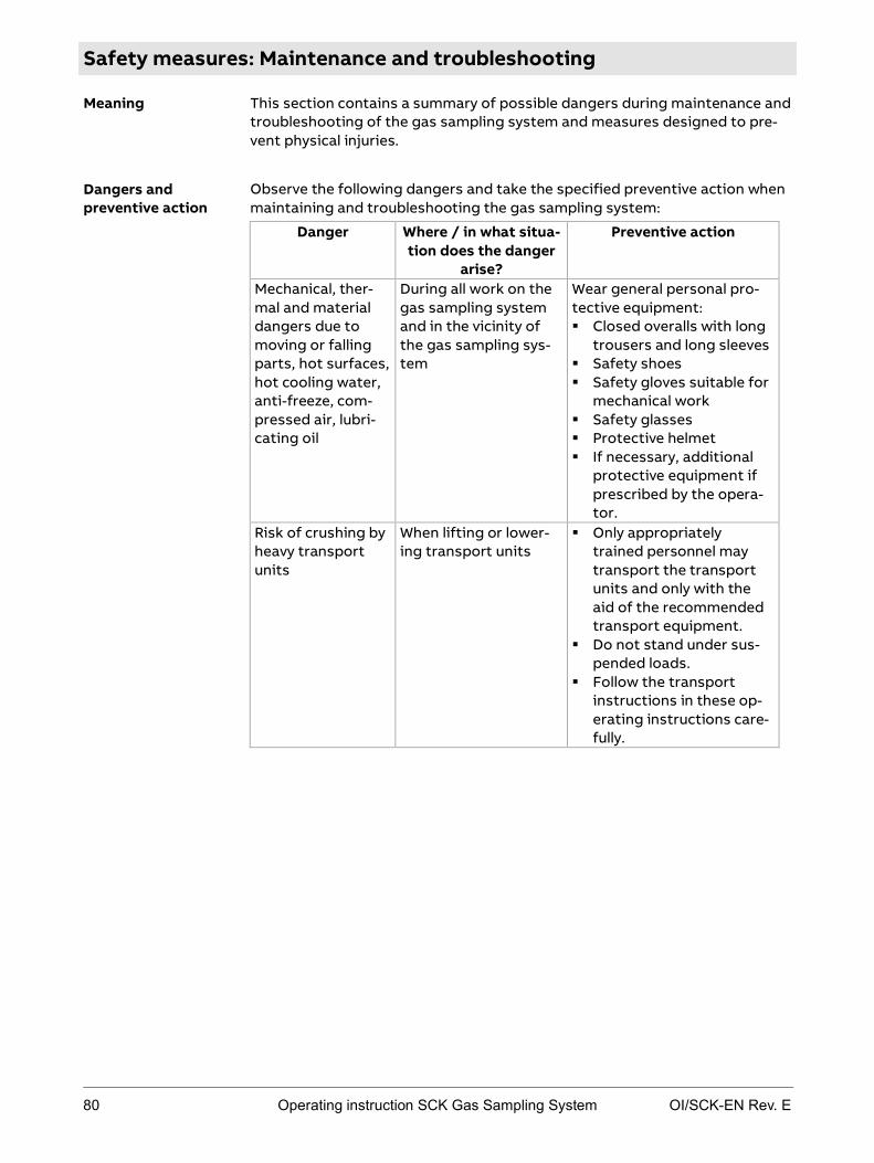
80 Operating instruction SCK Gas Sampling System OI/SCK-EN Rev. E
Safety measures: Maintenance and troubleshooting
This section contains a summary of possible dangers during maintenance and troubleshooting of the gas sampling system and measures designed to pre-vent physical injuries.
Observe the following dangers and take the specified preventive action when maintaining and troubleshooting the gas sampling system:
Danger Where / in what situa-tion does the danger
arise?
Preventive action
Mechanical, ther-mal and material dangers due to moving or falling parts, hot surfaces, hot cooling water, anti-freeze, com-pressed air, lubri-cating oil
During all work on the gas sampling system and in the vicinity of the gas sampling sys-tem
Wear general personal pro-tective equipment: Closed overalls with long
trousers and long sleeves Safety shoes Safety gloves suitable for
mechanical work Safety glasses Protective helmet If necessary, additional
protective equipment if prescribed by the opera-tor.
Risk of crushing by heavy transport units
When lifting or lower-ing transport units
Only appropriately trained personnel may transport the transport units and only with the aid of the recommended transport equipment.
Do not stand under sus-pended loads.
Follow the transport instructions in these op-erating instructions care-fully.
Meaning
Dangers and preventive action
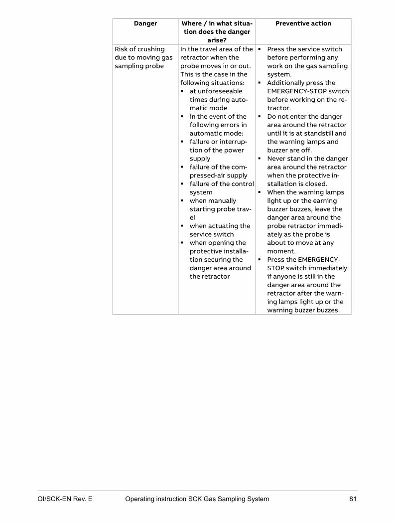
OI/SCK-EN Rev. E Operating instruction SCK Gas Sampling System 81
Danger Where / in what situa-tion does the danger
arise?
Preventive action
Risk of crushing due to moving gas sampling probe
In the travel area of the retractor when the probe moves in or out. This is the case in the following situations: at unforeseeable
times during auto-matic mode
in the event of the following errors in automatic mode:
failure or interrup-tion of the power supply
failure of the com-pressed-air supply
failure of the control system
when manually starting probe trav-el
when actuating the service switch
when opening the protective installa-tion securing the danger area around the retractor
Press the service switch before performing any work on the gas sampling system.
Additionally press the EMERGENCY-STOP switch before working on the re-tractor.
Do not enter the danger area around the retractor until it is at standstill and the warning lamps and buzzer are off.
Never stand in the danger area around the retractor when the protective in-stallation is closed.
When the warning lamps light up or the earning buzzer buzzes, leave the danger area around the probe retractor immedi-ately as the probe is about to move at any moment.
Press the EMERGENCY-STOP switch immediately if anyone is still in the danger area around the retractor after the warn-ing lamps light up or the warning buzzer buzzes.

82 Operating instruction SCK Gas Sampling System OI/SCK-EN Rev. E
Danger Where / in what situa-tion does the danger
arise?
Preventive action
Danger due to current-carrying parts
When working on elec-tric components
Only specialized electrical personnel may work on the electrical system.
Disconnect the gas sam-pling system from the power supply before working on other electric components.
Observe national regula-tions pertaining to elec-trical equipment.
The main terminals -X30, -X40 and the input termi-nals of the main switches -Q30, -Q40 are live even when the main switches are off.
All metallic parts in the environment that can be touched at the same time as the machine must also be grounded together.
Check pre-protection according to the docu-mentation.
Risk of burning due to hot surfaces
The gas sampling system is very hot during and after opera-tion of the gas sam-pling system, particu-larly: the cooling module the heated sample
gas lines the connection box
for the heated sam-ple gas line on the retractor
the heated sam-pling filter
the entire gas sam-pling probe
the metal structure of the retractor
the shutter of the duct opening
Do not touch the gas sampling system during and after operation.
Do not touch the gas sampling system until it has cooled down to less than 50 °C.
If it is unavoidable to touch during operation, wear a face mask against heat, heat-proof gloves and protective welder's clothing.

OI/SCK-EN Rev. E Operating instruction SCK Gas Sampling System 83
Danger Where / in what situa-tion does the danger
arise?
Preventive action
Risk of burning due to falling or spall-ing material.
After the probe moves out of the rotary kiln, hot material may fall or spall off the probe.
Never enter the danger area around the retractor during operation.
Do not approach the retracted probe until it has cooled down.
If it is unavoidable to approach the hot probe, wear a face mask against heat, heat-proof gloves and protective welder's clothing.
Risk of burning due to hot surfaces, hot gases, jet flames
At the duct opening when inspecting and cleaning the wall tube
Preferably inspect the wall tube when the rotary kiln is out of operation.
If you check or clean the wall tube when the rotary kiln is in operation: Wear a face mask against
heat, heat-proof gloves and protective welder's clothing and respiratory protection against toxic gases.
Keep the time in which the duct opening is open as short as possible.
Danger due to harmful gases, jet flames
Due to gases escaping from the duct opening of the rotary kiln
Ensure adequate ventila-tion of the work place.
Only enter the danger area around the retractor when the shutter is closed.
Lock the shutter before commencing work, if this is indicated.
If work is unavoidable in the area of the duct open-ing, wear respiratory pro-tection.
Risk of scalding due to hot cooling water
When working on the cooling water system, particularly: ventilation open-
ings screw connections
Do not perform work on the cooling water circuit until the gas sampling system has cooled down.

84 Operating instruction SCK Gas Sampling System OI/SCK-EN Rev. E
Danger Where / in what situa-tion does the danger
arise?
Preventive action
Danger due to harmful anti-freeze
In the cooling water of the cooling system
Avoid contact with the cooling water and the an-ti-freeze.
Wash any cooling water and anti-freeze off the skin immediately with wa-ter and soap.
If cooling water or anti-freeze gets in the eyes despite protective glass-es, rinse them thoroughly under running water, holding the eyelids open.
Observe instructions in the anti-freeze manufac-turer's safety data sheet.
Danger due to harmful lubricating oil
In the pneumatic box, on the pneumatic motor filter muffler, inside the pneumatic motor.
Avoid contact with lubri-cating oil.
Wash any lubricating oil off the skin immediately with water and soap.
If any lubricating oil gets in the eyes despite pro-tective glasses, rinse them thoroughly under running water, holding the eyelids open.
Observe instructions in the lubricating oil manu-facturer's safety data sheet.
Danger due to harmful dust
While cleaning the gas sampling system
Wear a dust mask. Wash any dust off the
skin immediately with wa-ter and soap.
Risk of slipping Around the gas sam-pling system due to cooling water or lubri-cating oil that escapes or is spilled.
Always keep the floor around the gas sampling system clean and dry.
OI/SCK-EN Rev. E Operating instruction SCK Gas Sampling System 85
Chapter 5 Transport and unpacking
Topic Page General transport information ..........................................................................86
Transport the system in the company .............................................................89
Unpacking the system ......................................................................................... 91
Scope of delivery .................................................................................................. 92

86 Operating instruction SCK Gas Sampling System OI/SCK-EN Rev. E
General transport information
Danger of crushing when lifting or lowering the transport unit Only appropriately trained personnel may transport the transport units and
only with the aid of the recommended transport equipment. Do not stand under suspended loads. Follow the transport instructions in these operating instructions care-
fully.
Risk of injury in the area of the gas sampling system due to moving or fall-ing parts, anti-freeze, lubricating oil
Wear general personal protective equipment:
Closed overalls with long trousers and long sleeves Safety shoes Safety gloves suitable for mechanical work Safety glasses Protective helmet If necessary, additional protective equipment if prescribed by the opera-
tor.
During transport make sure that the transport packaging is not damaged or removed. Observe the below-mentioned temperature and humidity limits during transport.
In the event of transport damage attributable to improper handling, instigate damage assessment by the carrier (rail, post office, and forwarder) within seven days.
Make sure that none of the enclosed accessories are lost during unpacking. Store the screws in case the unit needs to be transported again in the future.
The retractor including the probe weighs 450–500 kg depending on the length of the retractor and type of probe. A crane and suitable transport equipment is required for transport and unpacking. Use the transport lugs to fasten the lifting ropes. The lifting ropes must be long enough to ensure an angle of at least 60° under strain. Otherwise the retractor cabinet can get twisted. If the cooling module is also transported by crane, observe the same points.
Heavy transport units
Mechanical and material dangers
General remarks regarding transport
Transport with crane
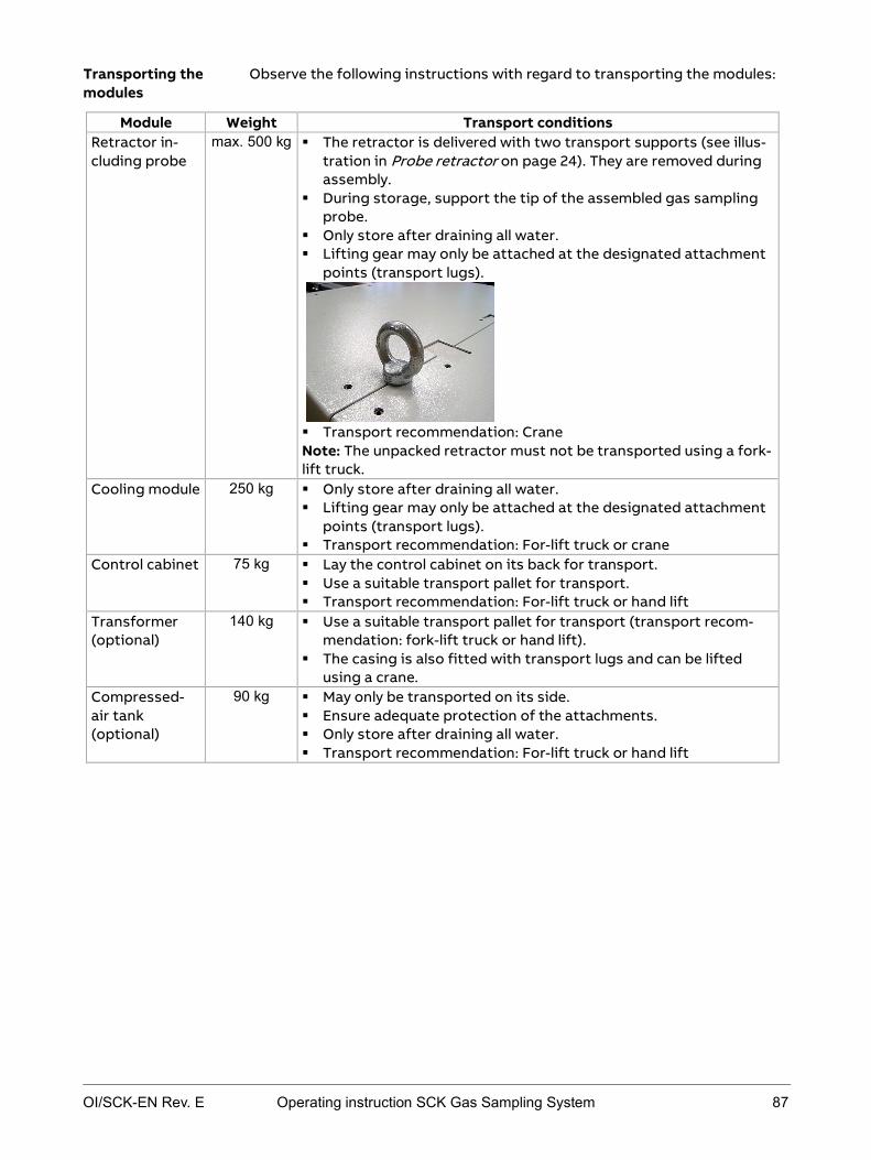
OI/SCK-EN Rev. E Operating instruction SCK Gas Sampling System 87
Observe the following instructions with regard to transporting the modules:
Module Weight Transport conditions Retractor in-cluding probe
max. 500 kg The retractor is delivered with two transport supports (see illus-tration in Probe retractor on page 24). They are removed during assembly.
During storage, support the tip of the assembled gas sampling probe.
Only store after draining all water. Lifting gear may only be attached at the designated attachment
points (transport lugs).
Transport recommendation: Crane Note: The unpacked retractor must not be transported using a fork-lift truck.
Cooling module 250 kg Only store after draining all water. Lifting gear may only be attached at the designated attachment
points (transport lugs). Transport recommendation: For-lift truck or crane
Control cabinet 75 kg Lay the control cabinet on its back for transport. Use a suitable transport pallet for transport. Transport recommendation: For-lift truck or hand lift
Transformer (optional)
140 kg Use a suitable transport pallet for transport (transport recom-mendation: fork-lift truck or hand lift).
The casing is also fitted with transport lugs and can be lifted using a crane.
Compressed-air tank (optional)
90 kg May only be transported on its side. Ensure adequate protection of the attachments. Only store after draining all water. Transport recommendation: For-lift truck or hand lift
Transporting the modules
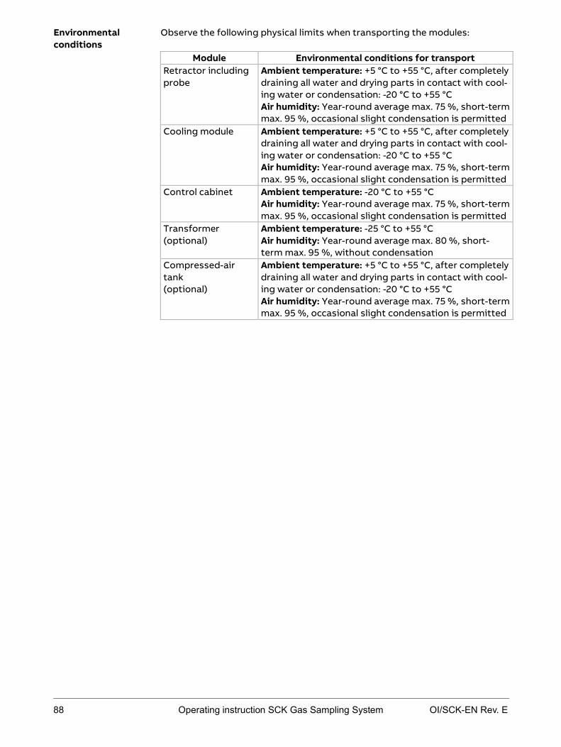
88 Operating instruction SCK Gas Sampling System OI/SCK-EN Rev. E
Observe the following physical limits when transporting the modules:
Module Environmental conditions for transport Retractor including probe
Ambient temperature: +5 °C to +55 °C, after completely draining all water and drying parts in contact with cool-ing water or condensation: -20 °C to +55 °C Air humidity: Year-round average max. 75 %, short-term max. 95 %, occasional slight condensation is permitted
Cooling module Ambient temperature: +5 °C to +55 °C, after completely draining all water and drying parts in contact with cool-ing water or condensation: -20 °C to +55 °C Air humidity: Year-round average max. 75 %, short-term max. 95 %, occasional slight condensation is permitted
Control cabinet Ambient temperature: -20 °C to +55 °C Air humidity: Year-round average max. 75 %, short-term max. 95 %, occasional slight condensation is permitted
Transformer (optional)
Ambient temperature: -25 °C to +55 °C Air humidity: Year-round average max. 80 %, short-term max. 95 %, without condensation
Compressed-air tank (optional)
Ambient temperature: +5 °C to +55 °C, after completely draining all water and drying parts in contact with cool-ing water or condensation: -20 °C to +55 °C Air humidity: Year-round average max. 75 %, short-term max. 95 %, occasional slight condensation is permitted
Environmental conditions

OI/SCK-EN Rev. E Operating instruction SCK Gas Sampling System 89
Transport the system in the company
Risk of injury in the area of the gas sampling system due to moving or fall-ing parts, anti-freeze, lubricating oil
Wear general personal protective equipment:
Closed overalls with long trousers and long sleeves Safety shoes Safety gloves suitable for mechanical work Safety glasses Protective helmet If necessary, additional protective equipment if prescribed by the opera-
tor.
Danger of crushing when lifting or lowering the transport unit Only appropriately trained personnel may transport the transport units and
only with the aid of the recommended transport equipment. Do not stand under suspended loads. Follow the transport instructions in these operating instructions care-
fully.
Observe the following instructions with regard to transport in the company:
Module Weight Transport conditions Retractor including probe
max. 500 kg Probe tip must be adequately fixed to the retractor (e.g. with a load strap) in order to avoid bouncing, that may damage the roll-ers and rails.
Use the two enclosed transport supports for transport in the company (see illustration in Probe retractor on page 24).
Lifting gear may only be attached at the designated attachment points (transport lugs).
Transport recommendation: Crane Note: Do not transport using a fork-lift truck.
Cooling mod-ule
250 kg Protect cooling fins with a board to avoid damage. Only store after draining all water. Lifting gear may only be attached at the designated attachment
points (transport lugs). Transport recommendation: For-lift truck or crane
Mechanical and material dangers
Heavy transport units
Transporting the modules

90 Operating instruction SCK Gas Sampling System OI/SCK-EN Rev. E
Module Weight Transport conditions Control cabi-net
75 kg Mark connecting cables so that you know where to install what. Lay the control cabinet on its back for transport. Use a suitable transport pallet for transport. Transport recommendation: For-lift truck or hand lift
Compressed- air tank
90 kg Disassemble the compressed-air system for transport. The compressed-air tank may only be transported on its side. Ensure adequate protection of the attachments. Transport recommendation: For-lift truck or hand lift
Transformer 140 kg Use a suitable transport pallet for transport. Lifting gear may only be attached at the designated attachment
points (transport lugs). Transport recommendation: For-lift truck, hand lift or crane

OI/SCK-EN Rev. E Operating instruction SCK Gas Sampling System 91
Unpacking the system
Risk of injury in the area of the gas sampling system due to moving or fall-ing parts, anti-freeze, lubricating oil
Wear general personal protective equipment:
Closed overalls with long trousers and long sleeves Safety shoes Safety gloves suitable for mechanical work Safety glasses Protective helmet If necessary, additional protective equipment if prescribed by the opera-
tor.
Danger of crushing when lifting or lowering the transport unit Only appropriately trained personnel may transport the transport units and
only with the aid of the recommended transport equipment. Do not stand under suspended loads. Follow the transport instructions in these operating instructions care-
fully.
Perform the following steps to unpack the system:
Step Procedure 1 Remove outer packaging:
Transport crate Tensioning straps Cardboard, films and wooden parts
2 Undo fasteners holding the system parts on the pallet. 3 Lift system parts off the pallet with a crane, fork-lift
truck or hand lift (observe transport recommendations in Transporting the system in the company on page 89). Note: The retractor must not be transported with a fork-lift truck.
4 Dispose of packaging material in accordance with the national regulations.
5 Transport system parts to the place of installation (see Transporting the system in the company on page 89).
Mechanical and material dangers
Heavy transport units
Instructions

92 Operating instruction SCK Gas Sampling System OI/SCK-EN Rev. E
Scope of delivery
The following components are delivered as standard:
Probe retractor including gas sampling probe (H or 60S) Control cabinet Cooling module Cooling water hose (30 m) Bottle of compressed-air lubricant (1 l) Complete documentation DE/EN on CD-ROM System manual
The following optional components may be included in the scope of delivery:
250-l compressed-air tank Compressed-air piping (25 m) Transformer IP44
Scope of delivery
Optional

OI/SCK-EN Rev. E Operating instruction SCK Gas Sampling System 93
Chapter 6 Installation
Topic Page Overview: installation ......................................................................................... 94
Checking site conditions .................................................................................... 95
Installing the probe retractor ............................................................................ 97
Installing the control cabinet .......................................................................... 100
Installing the compressed-air supply ............................................................. 101
Installing the cooling module........................................................................... 103
Installing the cooling water circuit ................................................................. 104
Connecting the sample gas line to the retractor ......................................... 105
Connecting internal electric cables ................................................................ 106
Connecting external electric cables ................................................................ 108

94 Operating instruction SCK Gas Sampling System OI/SCK-EN Rev. E
Overview: installation
This section contains a list of tasks to be performed when installing the gas sampling system. Links are given to the specific installation instructions describing installation of the various modules in detail.
It is recommended to have initial startup of the gas sampling system per-formed by the manufacturer's trained personnel or by the supplier.
In order to be able to install the various modules of the gas sampling system, preparations must be made at the cement works. A list of preparatory tasks is given in the "Engineering Guideline".
The rotary kiln must be shut down during installation of the wall tube. Instal-lation of the gas sampling system should also preferably be performed while the kiln is shut down. If installation is performed while the kiln is operating, personnel must always wear adequate heat-proof clothing during assembly of the probe retractor (uncovered duct opening!).
Proceed as follows to install the complete system:
Step Procedure Instructions in ...
1 Check place of installation of the various modules of the gas sampling system.
Checking site conditions on page 95
2 Install the probe retractor such that personnel are not endangered and the system cannot be dam-aged.
Installing the probe retractor on page 97
3 Install control cabinet in suitable place.
Installing the control cabinet on page 100
4 Install compressed-air supply, install com-pressed-air tank if neces-sary.
Installing the compressed-air supply on page 101
5 Install cooling module. Installing the cooling module on page 103
6 Lay and connect cooling water hoses.
Installing the cooling water circuit on page 104
7 Connect external sample gas line to retractor.
Connecting the sample gas line to the retractor on page 105
8 Connect electric lines. Connecting internal electric cables on page 106
9 Connect external electric cables.
Connecting external electric cables on page 108
Introduction
Preparations for installations and installation
Instructions
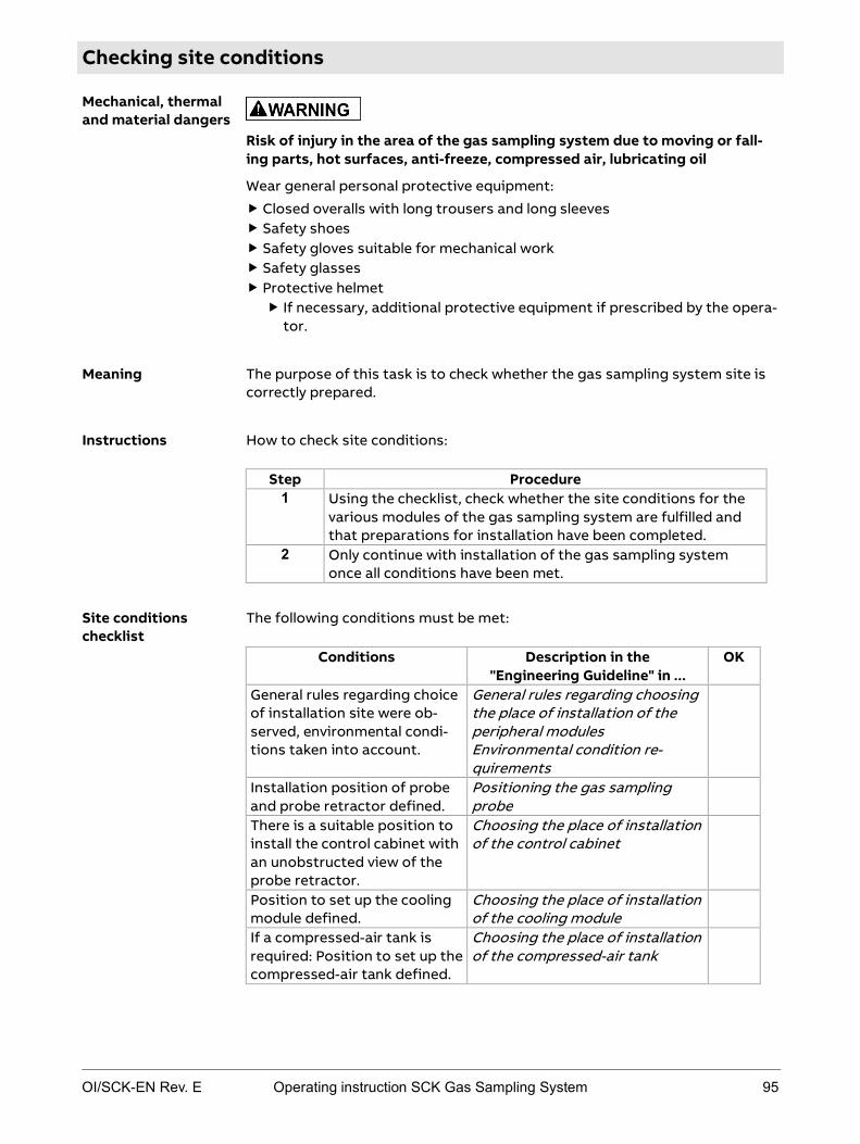
OI/SCK-EN Rev. E Operating instruction SCK Gas Sampling System 95
Checking site conditions
Risk of injury in the area of the gas sampling system due to moving or fall-ing parts, hot surfaces, anti-freeze, compressed air, lubricating oil
Wear general personal protective equipment:
Closed overalls with long trousers and long sleeves Safety shoes Safety gloves suitable for mechanical work Safety glasses Protective helmet If necessary, additional protective equipment if prescribed by the opera-
tor.
The purpose of this task is to check whether the gas sampling system site is correctly prepared.
How to check site conditions:
Step Procedure 1 Using the checklist, check whether the site conditions for the
various modules of the gas sampling system are fulfilled and that preparations for installation have been completed.
2 Only continue with installation of the gas sampling system once all conditions have been met.
The following conditions must be met:
Conditions Description in the "Engineering Guideline" in ...
OK
General rules regarding choice of installation site were ob-served, environmental condi-tions taken into account.
General rules regarding choosing the place of installation of the peripheral modules Environmental condition re-quirements
Installation position of probe and probe retractor defined.
Positioning the gas sampling probe
There is a suitable position to install the control cabinet with an unobstructed view of the probe retractor.
Choosing the place of installation of the control cabinet
Position to set up the cooling module defined.
Choosing the place of installation of the cooling module
If a compressed-air tank is required: Position to set up the compressed-air tank defined.
Choosing the place of installation of the compressed-air tank
Mechanical, thermal and material dangers
Meaning
Instructions
Site conditions checklist

96 Operating instruction SCK Gas Sampling System OI/SCK-EN Rev. E
Conditions Description in the "Engineering Guideline" in ...
OK
A suspension device for the probe retractor has been pre-pared and holes drilled for installation of the other mod-ules.
Fastening elements and attach-ment points
Wall tube and mounting flange manufactured and installed.
Creating the wall tube with mounting flange Installing the wall tube
The power and compressed-air supply conforms to the re-quirements of the gas sam-pling system.
Power and compressed-air supply requirements
Air cannon, if present, is inte-grated into the gas sampling system control system only.
Integrating the air cannon into the control system
The danger area around the probe retractor is protected by a protective installation.
Creating the base area for the retractor Creating the protective installa-tion around the retractor
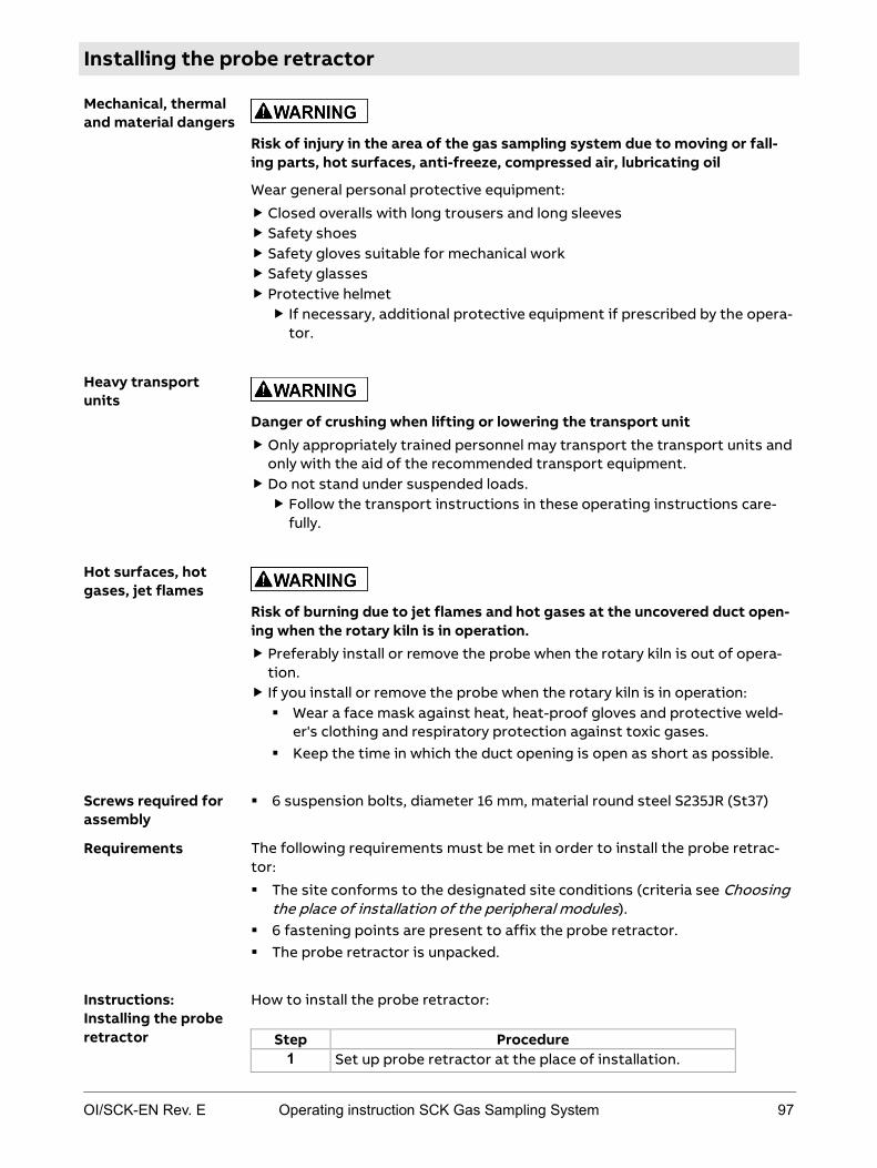
OI/SCK-EN Rev. E Operating instruction SCK Gas Sampling System 97
Installing the probe retractor
Risk of injury in the area of the gas sampling system due to moving or fall-ing parts, hot surfaces, anti-freeze, compressed air, lubricating oil
Wear general personal protective equipment:
Closed overalls with long trousers and long sleeves Safety shoes Safety gloves suitable for mechanical work Safety glasses Protective helmet If necessary, additional protective equipment if prescribed by the opera-
tor.
Danger of crushing when lifting or lowering the transport unit Only appropriately trained personnel may transport the transport units and
only with the aid of the recommended transport equipment. Do not stand under suspended loads. Follow the transport instructions in these operating instructions care-
fully.
Risk of burning due to jet flames and hot gases at the uncovered duct open-ing when the rotary kiln is in operation. Preferably install or remove the probe when the rotary kiln is out of opera-
tion. If you install or remove the probe when the rotary kiln is in operation: Wear a face mask against heat, heat-proof gloves and protective weld-
er's clothing and respiratory protection against toxic gases. Keep the time in which the duct opening is open as short as possible.
6 suspension bolts, diameter 16 mm, material round steel S235JR (St37)
The following requirements must be met in order to install the probe retrac-tor:
The site conforms to the designated site conditions (criteria see Choosing the place of installation of the peripheral modules).
6 fastening points are present to affix the probe retractor. The probe retractor is unpacked.
How to install the probe retractor:
Step Procedure 1 Set up probe retractor at the place of installation.
Mechanical, thermal and material dangers
Heavy transport units
Hot surfaces, hot gases, jet flames
Screws required for assembly
Requirements
Instructions: Installing the probe retractor

98 Operating instruction SCK Gas Sampling System OI/SCK-EN Rev. E
Step Procedure 2 Suspend probe retractor on transport lugs (see photo)
using suitable lifting gear.
Note: Pay particular attention to suitable fastening points of the lifting equipment. Observe relevant local regulations.
3 Lift probe retractor so far that you can remove the two mounted transport supports. Note: Store the transport supports for any future transport.
4 Position probe retractor in the designated position and install appropriate support.
5 Connect the fastening elements of the probe retractor and the system. There are 6 fastening straps on the probe retractor for this purpose (see Figure). Maximum load per suspension point is 10,000 N; ensure even load-ing of the fastening elements.
CAUTION! The screw-in transport lugs are for transport-ing the probe retractor only but not for permanent sus-pension. For permanent suspension of the probe re-tractor, only use the 6 designated fastening straps.
6 Remove dummy flange on wall tube. WARNING! Risk of burning due to jet flames and hot gases at the uncovered duct opening when the rotary kiln is in operation. Wear a face mask against heat, heat-proof gloves and protective welder's clothing and respiratory protection against toxic gases.
7 Flange the mounting flange of the probe retractor on the kiln wall tube.
8 Remove lifting gear and support material. 9 Check whether probe retractor is fastened stably
enough and adjusted to local conditions.
During assembly it may be necessary to move the probe retractor without with compressed-air supply or control cabinet. However, this should be lim-ited to absolutely necessary cases. Proceed as follows:
Moving the probe during assembly
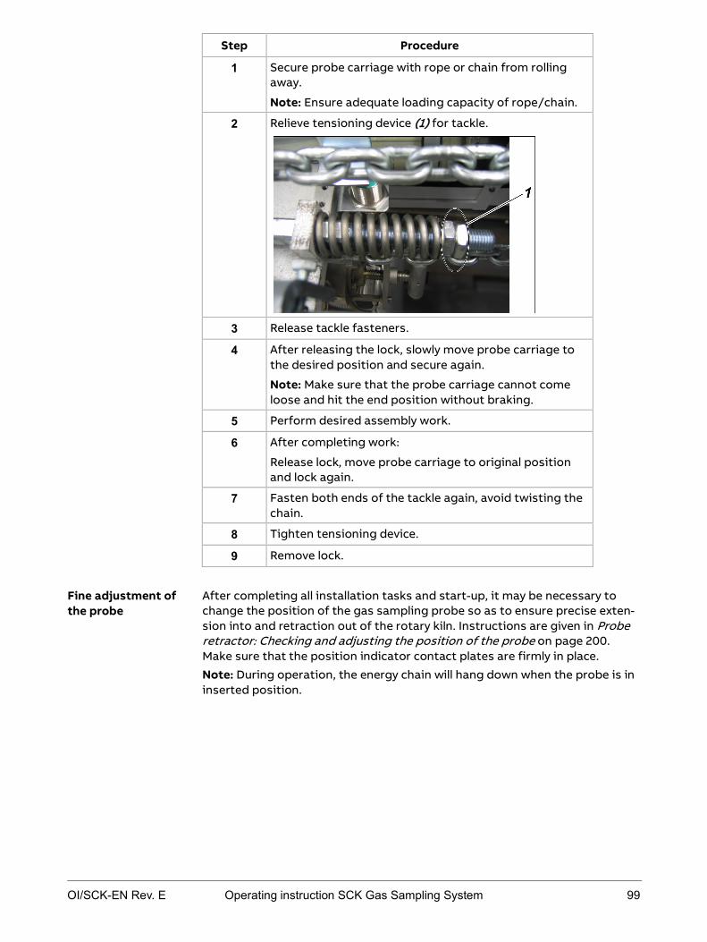
OI/SCK-EN Rev. E Operating instruction SCK Gas Sampling System 99
Step Procedure
1 Secure probe carriage with rope or chain from rolling away.
Note: Ensure adequate loading capacity of rope/chain.
2 Relieve tensioning device (1) for tackle.
3 Release tackle fasteners.
4 After releasing the lock, slowly move probe carriage to the desired position and secure again.
Note: Make sure that the probe carriage cannot come loose and hit the end position without braking.
5 Perform desired assembly work.
6 After completing work:
Release lock, move probe carriage to original position and lock again.
7 Fasten both ends of the tackle again, avoid twisting the chain.
8 Tighten tensioning device.
9 Remove lock.
After completing all installation tasks and start-up, it may be necessary to change the position of the gas sampling probe so as to ensure precise exten-sion into and retraction out of the rotary kiln. Instructions are given in Probe retractor: Checking and adjusting the position of the probe on page 200. Make sure that the position indicator contact plates are firmly in place.
Note: During operation, the energy chain will hang down when the probe is in inserted position.
Fine adjustment of the probe

100 Operating instruction SCK Gas Sampling System OI/SCK-EN Rev. E
Installing the control cabinet
Risk of injury in the area of the gas sampling system due to moving or fall-ing parts, hot surfaces, anti-freeze, compressed air, lubricating oil
Wear general personal protective equipment:
Closed overalls with long trousers and long sleeves Safety shoes Safety gloves suitable for mechanical work Safety glasses Protective helmet If necessary, additional protective equipment if prescribed by the opera-
tor.
Danger of crushing when lifting or lowering the transport unit Only appropriately trained personnel may transport the transport units and
only with the aid of the recommended transport equipment. Do not stand under suspended loads. Follow the transport instructions in these operating instructions care-
fully.
4 galvanized steel screws (or stainless material) M10 or bolts M10
The following requirements must be met in order to install the control cabi-net:
The site conforms to the designated site conditions (criteria see Choosing the place of installation of the peripheral modules).
Fastening points are present to affix the control cabinet. The control cabinet is unpacked.
How to install the control cabinet:
Step Procedure
1 Fasten control cabinet in suitable position (see Choos-ing the place of installation of the control cabinet) with 4 assembly screws or bolts.
Mechanical, thermal and material dangers
Heavy transport units
Screws required for assembly
Requirements
Instructions

OI/SCK-EN Rev. E Operating instruction SCK Gas Sampling System 101
Installing the compressed-air supply
Risk of injury in the area of the gas sampling system due to moving or fall-ing parts, hot surfaces, anti-freeze, compressed air, lubricating oil
Wear general personal protective equipment:
Closed overalls with long trousers and long sleeves Safety shoes Safety gloves suitable for mechanical work Safety glasses Protective helmet If necessary, additional protective equipment if prescribed by the opera-
tor.
The location of the pneumatic connections on the probe retractor can be found in the pneumatic/hydraulic interface plan in the appendix. All required lines are pre-installed in the probe retractor area. All downline connections as connected from the central connection point on top of the probe retractor.
Pneumatic/hydraulic interface plan
The following assembly screws are required for installation of the com-pressed-air tank:
3 galvanized steel screws (or stainless material) or bolts M12
The following conditions must be met:
Compressed air conforms to the required quality of compressed air; see Power and compressed-air supply conditions.
When setting up the compressed-air tank: The site conforms to the desig-nated site conditions (criteria see Choosing the place of installation of the peripheral modules).
Proceed as follows to install the compressed-air tank:
Step Procedure
1 Fasten compressed-air tank in suitable position (see Choosing the place of installation of the compressed-air tank) with 3 galvanized steel screws (or stainless material) or bolts M12 on the ground.
2 Pneumatically connect compressed-air tank as per pneumatic/-hydraulic interface plan (see appendix) to the gas sampling system.
Mechanical, thermal and material dangers
Position of the connections
Required documents
Assembly screws for compressed-air tank
Requirements
Connecting the compressed-air tank (optional)

102 Operating instruction SCK Gas Sampling System OI/SCK-EN Rev. E
Connect the compressed-air tubes as follows:
Step Procedure
1 Cut the compressed-air tubes to length.
2 Lay and fasten compressed-air tubes along designated path.
3 Connect compressed-air tubes to the module screw connectors as per the pneumatic/hydraulic interface plan in the appendix.
Make sure that the compressed-air supply cannot ice up in ambient tempera-tures below 0 °C, e.g. by installing auxiliary heating.
Observe the following rules:
Pneumatic connections must be installed so as to rule out any damage caused by working in the proximity of the sampling system. ABB recom-mends installing tubes on trays or in tube conduits.
Minimum bending radius of the compressed-air tube is 100 mm. If this is not possible for technical reasons, ABB recommends installing suitable pipe adapters.
You can run the tubes for the necessary pneumatic connections ("central compressed-air supply", "compressed-air tank flow", "compressed-air tank return") either via the central connection point of the probe retractor or di-rectly to the screw connectors of the pneumatic box.
Run the tubes via the central connection area as follows:
Step Procedure
1 Remove cover panels at rear of probe retractor.
2 Insert tubes in the existing cable/tube trough and fasten with cable ties.
3 Connect to the screw connectors.
4 Replace cover panels and screw in place.
Connecting the compressed-air tubes
Preventing icing
Installing tubes
Alternative mode of installing tubes
OI/SCK-EN Rev. E Operating instruction SCK Gas Sampling System 103
Installing the cooling module
Risk of injury in the area of the gas sampling system due to moving or fall-ing parts, hot surfaces, anti-freeze, compressed air, lubricating oil
Wear general personal protective equipment:
Closed overalls with long trousers and long sleeves Safety shoes Safety gloves suitable for mechanical work Safety glasses Protective helmet If necessary, additional protective equipment if prescribed by the opera-
tor.
Danger of crushing when lifting or lowering the transport unit Only appropriately trained personnel may transport the transport units and
only with the aid of the recommended transport equipment. Do not stand under suspended loads. Follow the transport instructions in these operating instructions care-
fully.
4 galvanized steel screws (or stainless material) M12x30 or bolts M12x30
The following requirements must be met in order to install the cooling mod-ule:
The site conforms to the designated site conditions (criteria see Choosing the place of installation of the peripheral modules).
Fastening points are present to affix the cooling module. The cooling module is unpacked.
How to install the cooling module:
Step Procedure
1 Fasten cooling module in suitable position (see Choos-ing the place of installation of the cooling module) with 4 assembly screws or bolts on the ground.
2 Attach suitable drain pipe to safety valve outlet -J62 in order to prevent danger of cooling water escaping.
Mechanical, thermal and material dangers
Heavy transport units
Screws required for assembly
Requirements
Instructions

104 Operating instruction SCK Gas Sampling System OI/SCK-EN Rev. E
Installing the cooling water circuit
Risk of injury in the area of the gas sampling system due to moving or fall-ing parts, hot surfaces, anti-freeze, compressed air, lubricating oil
Wear general personal protective equipment:
Closed overalls with long trousers and long sleeves Safety shoes Safety gloves suitable for mechanical work Safety glasses Protective helmet If necessary, additional protective equipment if prescribed by the opera-
tor.
The location of the connections on the various modules can be found in the pneumatic/hydraulic interface plan in the appendix. All required lines are pre-installed in the probe retractor area. All downline connections as connected from the central connection point on top of the probe retractor.
Pneumatic/hydraulic interface plan
Hose clamps
Prepare the cooling-water hoses as follows:
Step Procedure 1 After assembling the probe retractor and cooling module,
determine the length of the cooling-water hoses. 2 Cut the cooling-water hoses to length. 3 Insert screw connectors into the ends of the hoses and secure
with hose clamps.
Install the cooling-water hoses as follows:
Step Procedure 1 Lay and fasten cooling-water hoses along designated path. 2 Connect cooling-water hoses to the module screw connectors
as per the pneumatic/hydraulic interface plan in the appendix.
Observe the following rules:
Install cooling-water hoses so as to rule out any damage caused by work-ing in the proximity of the gas sampling system. ABB recommends in-stalling tubes on trays or in tube conduits.
Minimum bending radius of the cooling-water hoses is 160 mm. If this is not possible for technical reasons, ABB recommends installing suitable pipe adapters.
Mechanical, thermal and material dangers
Position of the connections
Required documents
Tools required
Preparation
Installing the cooling-water hoses
Installing tubes

OI/SCK-EN Rev. E Operating instruction SCK Gas Sampling System 105
Connecting the sample gas line to the retractor
Risk of injury in the area of the gas sampling system due to moving or fall-ing parts, hot surfaces, anti-freeze, compressed air, lubricating oil
Wear general personal protective equipment:
Closed overalls with long trousers and long sleeves Safety shoes Safety gloves suitable for mechanical work Safety glasses Protective helmet If necessary, additional protective equipment if prescribed by the opera-
tor.
Pneumatic/hydraulic interface plan
How to connect the sample gas line to the analyzer system:
Step Procedure
1 The connector from the sample gas line to the probe retractor cable drag chain can be found in the pneumat-ic/hydraulic interface plan in the appendix. If further information is required on installation and connection to the analyzer system, consult the operating instructions of the analyzer system and analysis line.
Note: These tasks apply only to connection of the sam-ple gas line to the analyzer system. The internal retractor sample gas line is delivered pre-installed.
Observe the following rules:
Install sample gas line separately from other lines. When laying the sample gas line, avoid tight curves, bending or crossing
other lines. Refer to the manufacturer's installation instructions for further details.
Mechanical, thermal and material dangers
Required documents
Instructions
Installation of the line

106 Operating instruction SCK Gas Sampling System OI/SCK-EN Rev. E
Connecting internal electric cables
Risk of injury in the area of the gas sampling system due to moving or fall-ing parts, hot surfaces, anti-freeze, compressed air, lubricating oil
Wear general personal protective equipment:
Closed overalls with long trousers and long sleeves Safety shoes Safety gloves suitable for mechanical work Safety glasses Protective helmet If necessary, additional protective equipment if prescribed by the opera-
tor.
Danger of electric shock when working on electric components Only specialized electrical personnel may work on the electrical system. Disconnect the gas sampling system from the power supply before work-
ing on the electrical components. Observe national regulations pertaining to electrical equipment.
The main terminals -X30, -X40 and the input terminals of the main switches -Q30, -Q40 are live even when the main switches are off.
All metallic parts in the environment that can be touched at the same time as the machine must also be grounded together.
Check pre-protection according to the documentation.
The location of the electric connections on the various modules can be found in the electrical connection plan in the appendix. All required lines are pre-installed in the probe retractor area. All downline connections are installed via the central connection point to the electrical terminal box.
Electrical connection plan
Mechanical, thermal and material dangers
Current-carrying components
Position of the connections
Required documents

OI/SCK-EN Rev. E Operating instruction SCK Gas Sampling System 107
Proceed as follows to connect internal electric lines:
Step Procedure
1 On the control cabinet: Turn off the main switch.
2 Install internal lines in accordance with the electrical connec-tion plan (see appendix). This applies to: 24 VDC control cabinet-cooling module line 230/400 VAC cable to cooling-water pump 230/400 VAC cable to heat exchanger fan motor 24 VDC cable to probe retractor 24/26/28/30 VAC cable to probe retractor (option "H") 230 VAC cable to probe heating (option "60S") 230 VAC cable to probe retractor Signal cable to analyzer cabinet System bus cable control cabinet - cooling module (see step
3) System bus cable probe retractor - cooling module (see step
3)
3 Connecting the system bus cable: Install system bus cable from control cabinet to cooling
module terminal box. Connect to the 9-pin D-Sub connector of the CAN bridge (1).
Install system bus cable from the probe retractor terminal box to the cooling module terminal box. Connect to the 9-pin D-Sub connector of the CAN bridge (2).
4 Connecting the system bus cable to the frequency converter:
Loosen the short system bus cable with T-piece (2) from its transport fixing and connect it to the CAN adapter (1) at the frequency converter.
Instructions

108 Operating instruction SCK Gas Sampling System OI/SCK-EN Rev. E
Connecting external electric cables
Risk of injury in the area of the gas sampling system due to moving or fall-ing parts, hot surfaces, anti-freeze, compressed air, lubricating oil
Wear general personal protective equipment:
Closed overalls with long trousers and long sleeves Safety shoes Safety gloves suitable for mechanical work Safety glasses Protective helmet If necessary, additional protective equipment if prescribed by the opera-
tor.
Danger of electric shock when working on electric components Only specialized electrical personnel may work on the electrical system. Disconnect the gas sampling system from the power supply before work-
ing on the electrical components. Observe national regulations pertaining to electrical equipment.
The main terminals -X30, -X40 and the input terminals of the main switches -Q30, -Q40 are live even when the main switches are off.
All metallic parts in the environment that can be touched at the same time as the machine must also be grounded together.
Check pre-protection according to the documentation.
The control unit of the sampling system is equipped with an Ethernet inter-face. This interface is intended solely for service purposes. Any other use is not allowed.
When using the Ethernet interface, external influences through the network connection can disturb the time characteristics of the control program and thus of the complete sampling system.
The location of the electric connections on the various modules can be found in the electrical connection plan in the appendix.
Electrical connection plan
The following conditions must be met before connecting the power supply lines:
Check that the voltage setting of the analyzer system matches the mains voltage.
Make sure the power supply leads have an adequately dimensioned protec-tive device (circuit breaker).
Mechanical, thermal and material dangers
Current-carrying components
Using the Ethernet Interface
Position of the connections Required documents
Requirements

OI/SCK-EN Rev. E Operating instruction SCK Gas Sampling System 109
Proceed as follows to connect power supply lines:
Step Procedure
1 On the control cabinet: Turn off the main switch.
2 Affix ground cable to ground bolt of control cabinet (1), cooling module (2) and probe retractor (3).
In order to ground the control cabinet, run the ground cable through cable connection M16 (4) on the side wall of the con-trol cabinet:
3 Install external electric lines in accordance with the specifica-
tions of the electrical connection plan (see appendix). This applies to: 230/400 VAC supply cable UPS supply cable 230 VAC (optional) Signal cable for movable protective installation Signal cable for external warning horn System status signal cable Profibus cable to analyzer cabinet (option "Profibus DP") Modbus cable to analyzer cabinet (option "ACX")
Instructions

110 Operating instruction SCK Gas Sampling System OI/SCK-EN Rev. E
The gas sampling system is fitted with an electric signal input that allows you to integrate an external protective installation to secure the danger area around the retractor. To do so, connect the appropriate switching output of the movable protective installation to the signal input (-X33 5/6 in the electri-cal connection plan).
In order to prevent dangers caused by a blast of air from an air cannon in the area of the wall tube, the air cannon must be integrated into the gas sampling system control system (see Integrating the air cannon into the control sys-tem). The control cabinet is fitted with an air cannon connector (-D32 64 in the electrical connection plan).
The control cabinet is fitted with a connector for an additional warning horn (-X33 7/8 in the electrical connection plan).
In addition to the integrated EMERGENCY-STOP switch, the probe retractor is fitted with a connector for an additional EMERGENCY-STOP switch. As deliv-ered, both connectors are jumpered (see Detail "A" in pneumatic/hydraulic interface plan). To connect an additional EMERGENCY-STOP switch, remove the jumper and connect the connection wires to the EMERGENCY-STOP switch.
Connection option for movable protective installation
Connection option for air cannon
Connection option for additional warning horn Connection option for additional EMERGENCY-STOP switch

OI/SCK-EN Rev. E Operating instruction SCK Gas Sampling System 111
Chapter 7 Start-up
Topic Page Overview: Start-up ............................................................................................. 112
Installation check ............................................................................................... 113
Preparing the cooling-water circuit ................................................................ 114
Preparing the compressed-air supply ............................................................ 116
Activation ............................................................................................................. 118
After switching on: working on the cooling module ................................... 121
Checking the pneumatic system ..................................................................... 123
Starting frequency converter and adapting control parameters.............. 124
Checking/correcting operating parameters ................................................ 126
Checks to perform when using probe H ........................................................ 127
Inserting the probe and switching to automatic mode .............................. 130

112 Operating instruction SCK Gas Sampling System OI/SCK-EN Rev. E
Overview: Start-up
Proceed as follows to start up the gas sampling system:
Step Procedure Instructions in ...
1 Check installation for proper condition.
Installation check on page 113
2 Fill cooling water and check water-tightness of the cooling-water circuit.
Preparing the cooling-water circuit on page 114
3 Check enclosed compressed-air supply, fill oiler.
Preparing the com-pressed-air supply on page 116
4 Switch on the gas sampling system.
Activation on page 118
5 After switching on: vent cool-ing-water circuit.
After switching on: Work-ing on the cooling mod-ule on page 121
6 Check pneumatic system with the aid of the compressed-air switch in the pneumatic box.
Checking the pneumatic system on page 123
7 In the control cabinet: check frequency converter settings and correct if necessary.
Checking frequency converter settings on page 124
8 Check operating parameters of the gas sampling system and correct if necessary.
Checking/correcting operating parameters on page 126
9 Only if using probe H: check current monitoring
relay settings. Check probe heating power
supply.
Checks to perform when using probe H on page 127
10 Insert the probe for the first time, then adjust the speed of the probe during operation, adjust oil delivery rate on the compressed-air oiler, and check direction of rotation of the heat exchanger.
Inserting the probe and switching to automatic mode on page 130
Instructions

OI/SCK-EN Rev. E Operating instruction SCK Gas Sampling System 113
Installation check
Risk of injury in the area of the gas sampling system due to moving or fall-ing parts, hot surfaces, anti-freeze, compressed air, lubricating oil
Wear general personal protective equipment:
Closed overalls with long trousers and long sleeves Safety shoes Safety gloves suitable for mechanical work Safety glasses Protective helmet If necessary, additional protective equipment if prescribed by the opera-
tor.
Check the installation for correct condition before start-up. The following section describes this procedure. If one of these requirements is not met, abort start-up and do not continue until the appropriate conditions have been created.
How to check the installation:
Step Procedure
1 Based on the checklist below, check whether the gas sampling system was installed correctly.
2 Only continue to start up the gas sampling system once all conditions have been met.
The following conditions must be met:
Conditions OK
No visible damage to the modules.
Connection and laying of electric lines checked.
Connection and laying of pneumatic lines checked.
Connection and laying of cooling-water lines checked.
Heat exchanger connected with a shielded cable.
Adherence to the bending radii of the installed lines and hoses checked.
Stable fastening of the modules checked.
Protective probe box fitted.
Mechanical, thermal and material dangers
Meaning
Instructions
Checklist

114 Operating instruction SCK Gas Sampling System OI/SCK-EN Rev. E
Preparing the cooling-water circuit
Risk of injury in the area of the gas sampling system due to moving or fall-ing parts, hot surfaces, hot cooling water, anti-freeze, compressed air, lubricating oil
Wear general personal protective equipment:
Closed overalls with long trousers and long sleeves Safety shoes Safety gloves suitable for mechanical work Safety glasses Protective helmet If necessary, additional protective equipment if prescribed by the opera-
tor.
Risk of falling on slippery floor due to escaped or spilled cooling water and lubricating oil or dirt Always keep the floor around the gas sampling system clean and dry.
Danger of injury to skin and eyes in the event of contact with cooling water or anti-freeze Avoid contact with the cooling water and the anti-freeze.
Wash any cooling water and anti-freeze off the skin immediately with water and soap.
If cooling water or anti-freeze gets in the eyes despite protective glass-es, rinse them thoroughly under running water, holding the eyelids open.
Observe instructions in the anti-freeze manufacturer's safety data sheet.
The closed cooling-water circuit must be filled with approx. 50 l potable water (do not use anti-corrosive). In ambient temperatures below 0 °C use approx. 20 l anti-freeze. ABB recommends Glykol as anti-freeze. Anti-freeze with anti-corrosive additive is not permitted.
If temperatures can be expected to fall below 0 °C, fill the cooling-water cir-cuit with anti-freeze before filling the cooling water:
Step Procedure 1 Open filler on cooling module and fill approx. 20 l anti-freeze.
Mechanical, thermal and material dangers
Slippery floor
Harmful anti-freeze
Cooling-water requirements
Ensuring anti-freeze protection

OI/SCK-EN Rev. E Operating instruction SCK Gas Sampling System 115
Proceed as follows (note: it is advisable for two people to perform this work):
Step Procedure 1 Connect the filling pipe to the cooling-water supply of the
cooling module. Note: Make sure that there are no dirt deposits in the filling pipe; rinse first. Note: The cooling water is tinted due to formation of metal oxides in the heat exchanger. The functional capability is not affected. Note: Cooling water filling pressure > 1 bar (1000 hPa).
2 On the top of the heat exchanger: Unscrew cap on drain valve and open vent cock (red).
3 Open drain valves (2) on gas sampling probe.
4 Slowly open the shut-off valve -J63 on the cooling module and
allow cooling water to flow in until cooling water appears at the drain valves of the heat exchanger and gas sampling probe.
5 Close shut-off valve -J63. 6 Close drain valves on heat exchanger and gas sampling probe. 7 Check pressure of cooling water in the controller and top up if
necessary (target cooling water pressure in cooled state: 1-1.5 bar (1000-1500 hPa)).
Proceed as follows:
Step Procedure 1 Check cooling water circuit for leaks. Remedy any leaks before
continuing with start-up.
Instructions: topping up cooling water
Instructions: check for leaks
116 Operating instruction SCK Gas Sampling System OI/SCK-EN Rev. E
Preparing the compressed-air supply
Risk of injury in the area of the gas sampling system due to moving or fall-ing parts, hot surfaces, hot cooling water, anti-freeze, compressed air, lubricating oil
Wear general personal protective equipment:
Closed overalls with long trousers and long sleeves Safety shoes Safety gloves suitable for mechanical work Safety glasses Protective helmet If necessary, additional protective equipment if prescribed by the opera-
tor.
Danger due to skin and eye injuries in the event of contact with lubricating oil from the pneumatic box of, from the filter muffler or from inside the pneumatic motor. Avoid contact with lubricating oil.
Wash any lubricating oil off the skin immediately with water and soap.
If any lubricating oil gets in the eyes despite protective glasses, rinse them thoroughly under running water, holding the eyelids open.
Observe instructions in the lubricating oil manufacturer's safety data sheet.
Lubricating oil "D" DIN 51502, kinematic viscosity 30 mm2/s(cST) at 40 °C (ISO VG 32, DIN 51519)
The compressed air must meet the following minimum requirements:
Dew point +3 °C
Pressure 6 bar (6000 hPa) positive pressure
Consumption approx. 3 m3/h
One probe travel (2 x 20 s) requires approx. 1 m3.
Other requirements are:
The compressed air must be free of dirt and oil/water droplets. At ambient temperatures below 0 °C make sure that the compressed-air
supply cannot freeze.
Mechanical, thermal and material dangers
Harmful lubricating oil
Lubricating oil requirements
Compressed-air requirements

OI/SCK-EN Rev. E Operating instruction SCK Gas Sampling System 117
Proceed as follows to check the compressed air:
Step Procedure 1 Check the quality of the compressed air at the connection to
the customer-side compressed-air system using a white cloth (see compressed-air specifications above). If you observe any oil, moisture or other impurities, abort start-up and do not continue until these residues have been permanently eliminat-ed.
Fill the compressed-air oiler before switching on the gas sampling system:
Step Procedure 1 Shut off the compressed-air using the gate valve (1) in the pneumat-
ic box of the probe retractor.
2 Completely drain the compressed-air tank (if present). 3 Unscrew the tank on the compressed-air oiler -J74 by turning it
counter-clockwise, fill suitable oil to the top quarter in the top in-spection window and screw tank back on.
4 Remove any oil residue with a cloth. 5 Open the compressed-air gate valve (1) again.
Checking compressed-air supply
Filling the compressed-air oiler

118 Operating instruction SCK Gas Sampling System OI/SCK-EN Rev. E
Activation
Risk of injury in the area of the gas sampling system due to moving or fall-ing parts, hot surfaces, hot cooling water, anti-freeze, compressed air, lubricating oil
Wear general personal protective equipment:
Closed overalls with long trousers and long sleeves Safety shoes Safety gloves suitable for mechanical work Safety glasses Protective helmet If necessary, additional protective equipment if prescribed by the opera-
tor.
Danger of electric shock when control cabinet is open, open connection or terminal boxes Only specialized electrical personnel may work on the electrical system. Observe national regulations pertaining to electrical equipment.
The main terminals -X30, -X40 and the input terminals of the main switches -Q30, -Q40 are live even when the main switches are off.
All metallic parts in the environment that can be touched at the same time as the machine must also be grounded together.
Check pre-protection according to the documentation.
Risk of crushing around the retractor due to gas sampling probe move-ments Do not stand in the danger area around the retractor. Press the EMERGENCY-STOP switch immediately if anyone is still in the
danger area around the retractor after the warning lamps light up or the warning buzzer buzzes.
The connected analyzer system must be switched on. Observe the warm-up time of the analyzer system.
The mechanical locking bar of the shutter must be removed before insert-ing the gas sampling probe for the first time.
The system must not have any visible damage (see also Checking general condition on page 141).
The customer-side central compressed-air supply is switched on.
Control cabinet key to open the control cabinet
Mechanical, thermal and material dangers
Current-carrying components
Gas sampling probe movements
Requirements
Tools required
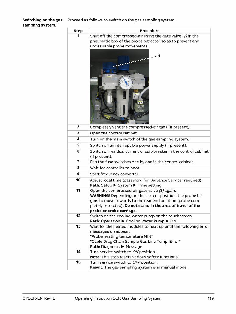
OI/SCK-EN Rev. E Operating instruction SCK Gas Sampling System 119
Proceed as follows to switch on the gas sampling system:
Step Procedure 1 Shut off the compressed-air using the gate valve (1) in the
pneumatic box of the probe retractor so as to prevent any undesirable probe movements.
2 Completely vent the compressed-air tank (if present). 3 Open the control cabinet. 4 Turn on the main switch of the gas sampling system. 5 Switch on uninterruptible power supply (if present). 6 Switch on residual current circuit-breaker in the control cabinet
(if present). 7 Flip the fuse switches one by one in the control cabinet. 8 Wait for controller to boot. 9 Start frequency converter.
10 Adjust local time (password for "Advance Service" required). Path: Setup ► System ► Time setting
11 Open the compressed-air gate valve (1) again. WARNING! Depending on the current position, the probe be-gins to move towards to the rear end position (probe com-pletely retracted). Do not stand in the area of travel of the probe or probe carriage.
12 Switch on the cooling-water pump on the touchscreen. Path: Operation ► Cooling Water Pump ► ON
13 Wait for the heated modules to heat up until the following error messages disappear: "Probe heating temperature MIN" "Cable Drag Chain Sample Gas Line Temp. Error" Path: Diagnosis ► Message
14 Turn service switch to ON position. Note: This step resets various safety functions.
15 Turn service switch to OFF position. Result: The gas sampling system is in manual mode.
Switching on the gas sampling system.

120 Operating instruction SCK Gas Sampling System OI/SCK-EN Rev. E
16 Perform the following checks to ensure smooth operation of the gas sampling system before inserting the gas sampling probe for the first time: After switching on: Working on the cooling module on page 121 Checking the pneumatic system on page 123 Checking frequency converter settings on page 124 Checking/correcting operating parameters on page 126 Checks to perform when using probe H on page 127
17 Close the control cabinet.

OI/SCK-EN Rev. E Operating instruction SCK Gas Sampling System 121
After switching on: working on the cooling module
Risk of injury in the area of the gas sampling system due to moving or fall-ing parts, hot surfaces, hot cooling water, anti-freeze, compressed air, lubricating oil
Wear general personal protective equipment:
Closed overalls with long trousers and long sleeves Safety shoes Safety gloves suitable for mechanical work Safety glasses Protective helmet If necessary, additional protective equipment if prescribed by the operator.
Danger of electric shock when control cabinet is open, open connection or terminal boxes Only specialized electrical personnel may work on the electrical system. Observe national regulations pertaining to electrical equipment.
The main terminals -X30, -X40 and the input terminals of the main switches -Q30, -Q40 are live even when the main switches are off.
All metallic parts in the environment that can be touched at the same time as the machine must also be grounded together.
Check pre-protection according to the documentation.
Danger of injury to skin and eyes in the event of contact with cooling water or anti-freeze. Avoid contact with the cooling water and the anti-freeze.
Wash any cooling water and anti-freeze off the skin immediately with water and soap.
If cooling water or anti-freeze gets in the eyes despite protective glass-es, rinse them thoroughly under running water, holding the eyelids open.
Observe instructions in the anti-freeze manufacturer's safety data sheet.
Risk of falling on slippery floor due to escaped or spilled cooling water and lubricating oil or dirt Always keep the floor around the gas sampling system clean and dry.
Control cabinet key to open the control cabinet The service switch is in the ON position, the gas sampling probe is retracted from the kiln (see Operating the service switch on page 161).
Mechanical, thermal and material dangers
Current-carrying components
Harmful anti-freeze
Slippery floor
Tools required Requirements

122 Operating instruction SCK Gas Sampling System OI/SCK-EN Rev. E
Proceed as follows:
Step Procedure
1 Open the control cabinet.
2 Switch off the cooling-water pump at the motor breaker -F37 (1).
Note: You can also switch off the cooling-water pump at circuit breaker -F36 (2).
3 Wait 5 minutes.
4 On the top of the heat exchanger: Unscrew cap on drain valve and open vent cock (red) so that air can escape.
5 Close drain valve on heat exchanger again as soon as only cool-ing water comes out of the drain valve.
6 Slowly open drain valve on the gas sampling probe.
7 Close drain valve on gas sampling probe again as soon as only cooling water comes out of the drain valve.
8 Switch cooling-water pump -M51 on again at motor breaker -F37 (1) or at circuit breaker -F36 (2) for approx. 20 s.
9 Wait 5 minutes, vent again.
10 Repeat step 8 through 9 if necessary until no more air comes out of the cooling-water circuit.
11 Check pressure of cooling water and top up if necessary (target cooling water pressure in cooled state: 1-1.5 bar (1000-1500 hPa)).
12 Close control cabinet again.
Note: Severe fluctuations of the cooling-water flow rate indicate that the cooling-water circuit needs to be vented again.
Instructions: venting the cooling-water circuit

OI/SCK-EN Rev. E Operating instruction SCK Gas Sampling System 123
Checking the pneumatic system
Risk of injury in the area of the gas sampling system due to moving or fall-ing parts, hot surfaces, hot cooling water, anti-freeze, compressed air, lubricating oil
Wear general personal protective equipment:
Closed overalls with long trousers and long sleeves Safety shoes Safety gloves suitable for mechanical work Safety glasses Protective helmet If necessary, additional protective equipment if prescribed by the opera-
tor.
The service switch is in the ON position, the gas sampling probe is retracted from the kiln (see Operating the service switch on page 161).
Proceed as follows to check compressed-air settings before first insertion.
Step Procedure
1 Check the compressed-air system with suitable equipment, see Checking for leaks on page 173.
2 Check the pressure switches in the pneumatic box for correct settings (5 bar (5000 hPa) and 3 bar (3000 hPa); see Figure).
Check mark in settings window and adjust with the setting screw on the head of the pressure switch if necessary.
Mechanical, thermal and material dangers
Requirements
Instructions

124 Operating instruction SCK Gas Sampling System OI/SCK-EN Rev. E
Starting frequency converter and adapting control parameters
Risk of injury in the area of the gas sampling system due to moving or fall-ing parts, hot surfaces, hot cooling water, anti-freeze, compressed air, lubricating oil
Wear general personal protective equipment:
Closed overalls with long trousers and long sleeves Safety shoes Safety gloves suitable for mechanical work Safety glasses Protective helmet If necessary, additional protective equipment if prescribed by the opera-
tor.
Danger of electric shock when control cabinet is open, open connection or terminal boxes Only specialized electrical personnel may work on the electrical system. Observe national regulations pertaining to electrical equipment. The main terminals -X30, -X40 and the input terminals of the main
switches -Q30, -Q40 are live even when the main switches are off.
All metallic parts in the environment that can be touched at the same time as the machine must also be grounded together.
Check pre-protection according to the documentation.
The frequency converter ACS355 controls the heat exchanger motor. In order to ensure constant cooling-water temperature, the factory-set default control parameters must be adapted to the conditions at the installation site.
Refer to the ACS355 manual for further information on operating the frequen-cy converter.
Control cabinet key to open the control cabinet
The following conditions must be met:
The service switch is in the ON position; the gas sampling probe is retracted from the kiln (see Operating the service switch on page 161).
Mechanical, thermal and material dangers
Current-carrying components
Meaning
Tools required
Requirements

OI/SCK-EN Rev. E Operating instruction SCK Gas Sampling System 125
Proceed as follows to start the frequency converter and adapt the control parameters:
Step Procedure 1 Open the control cabinet. 2 In the control cabinet: Start the frequency converter ACS 355
(1) by pressing the START button. Check whether "REM" (for remote mode) is indicated on the left side of the display and change by pressing the LOC REM button if required. Result: The frequency converter displays "A5011" for approx. 2 seconds.
Note: The frequency converter must be restarted after each system power failure. The following steps 3 to 10 must be executed only during the first system start-up and not after a system power failure.
3 Close control cabinet. 4 Turn service switch to OFF position. 5 Insert probe. 6 Monitor cooling water return temperature.
Path: Diagnosis ► Trends ► Cooling water return Note: If the set points are exceeded due to inadequate adapta-tion of the control parameters, the program sequences for the protection of the probe are started automatically.
7 Adjust control parameter KP in small steps until the cooling water return temperature runs as constant as possible (de-fault: -2). Path: Setup ► FC parameters Note: Enter the KP value always negative using the +/– button.
8 Adjust control parameter KI to further optimize the tempera-ture run (TN, default: 10).
9 If necessary, also adjust control parameter KD (TV, default: 0). 10
Save control parameter settings using the button.
Instructions

126 Operating instruction SCK Gas Sampling System OI/SCK-EN Rev. E
Checking/correcting operating parameters
The gas sampling system control system has factory settings that need to be modified to specific system conditions at start-up. You can edit alarm limits in a set range to suit specific system conditions. Limited configuration serves to protect the probe retractor against harmful or contradictory settings. A list of operating parameters can be found in Default operating parameter set-tings on page 48. You can display the operating parameters on the control cabinet touchscreen (Setup ► Time Parameters, Setup ► Limit Parameters, Setup ► Basic Parameters).
Refer to Optimizing operating parameters on page 51 for details on editing operating parameters.
Modifying the SCK controller operating parameters

OI/SCK-EN Rev. E Operating instruction SCK Gas Sampling System 127
Checks to perform when using probe H
Danger of electric shock when control cabinet is open, open connection or terminal boxes Only specialized electrical personnel may work on the electrical system. Observe national regulations pertaining to electrical equipment. The main terminals -X30, -X40 and the input terminals of the main switches
-Q30, -Q40 are live even when the main switches are off. All metallic parts in the environment that can be touched at the same time
as the machine must also be grounded together. Check pre-protection according to the documentation.
In addition to the usual checks when starting up the probe for the first time, additional checks are required when using probe H.
These are:
Checking current monitoring relay settings Checking probe H heating power supply
The following illustration shows the position of current monitoring relays -K35 and -K36 in the control cabinet:
Control cabinet key to open the control cabinet
The following conditions must be met:
The service switch is in the ON position, the gas sampling probe is retracted from the kiln (see Operating the service switch on page 161).
Current-carrying components
Meaning
Position
Tools required
Requirements

128 Operating instruction SCK Gas Sampling System OI/SCK-EN Rev. E
How to check the current monitoring relays for correct settings:
Step Procedure
1 Open the control cabinet.
2 Check current monitoring relays -K35 and -K36 for correct set-tings.
Settings for -K35 and -K36:
Hysteresis 5%
Threshold 4,5 A
Tripping delay 0,1 s
Start-up delay 5 s
There is a DIP switch under the white flap. Check the following settings here:
1 Undercurrent monitor-ing
ON
2 NC contact operation ON
3 Storage off OFF
4 (Default) OFF
3 Close the control cabinet.
Checking current monitoring relays

OI/SCK-EN Rev. E Operating instruction SCK Gas Sampling System 129
The electric heating of probe H is driven by a fixed voltage generated by the transformer installed in the control cabinet. Excessively long supply lines or incorrectly chosen cross-sections of the supply lines can lead to massive voltage drops en route to the gas sampling probe. This leads to reduced heating output and problems with probe operation.
Proceed as follows:
Step Procedure
1 Check voltage between Ground and the probe-side terminal connections (1) or (2).
2 The following minimum values must be reached:
Probe length / m 1,5 2 2,5 3 3,5
Minimum voltage / V 24 26 26 28 30
If these values are not reached, the system must not be put into operation in this set-up as adequate heating of the inte-grated metal filter cannot be guaranteed and this may lead to condensation and clogging of the probe.
Check the following possibilities for adequate supply: Lay larger cross-sections Reduce lengths of supply lines
Checking the probe H heating power supply

130 Operating instruction SCK Gas Sampling System OI/SCK-EN Rev. E
Inserting the probe and switching to automatic mode
Risk of injury in the area of the gas sampling system due to moving or fall-ing parts, hot surfaces, anti-freeze, compressed air, lubricating oil
Wear general personal protective equipment:
Closed overalls with long trousers and long sleeves Safety shoes Safety gloves suitable for mechanical work Safety glasses Protective helmet If necessary, additional protective equipment if prescribed by the opera-
tor.
Risk of crushing around the retractor due to gas sampling probe move-ments Before commencing any work on the gas sampling system, turn the service
switch to "ON" and secure the service switch against unauthorized switch-ing (with a padlock).
Additionally press the EMERGENCY-STOP switch before working on the retractor or probe.
Do not enter the danger area around the retractor until it is at standstill and the warning lamps and buzzer are off.
Never stand in the danger area around the retractor when the protective installation is closed.
When the warning lamps light up or the earning buzzer buzzes, leave the danger area around the probe retractor immediately as the probe is about to move at any moment. Press the EMERGENCY-STOP switch immediately if anyone is still in the
danger area around the retractor after the warning lamps light up or the warning buzzer buzzes.
The following conditions must be met:
The service switch is in the ON position, the gas sampling probe is retracted from the kiln (see Operating the service switch on page 161).
Proceed as follows:
Step Procedure 1 Make sure that the mechanical locking bar of the shutter is
removed. 2 Check wall tube for clogging and clean if necessary.
Note: Inserting the gas sampling probe when the duct opening is clogged can lead to damage to the probe and is therefore not permitted.
3 Leave danger area around the retractor, close protective instal-lation and turn service switch to OFF position.
Mechanical, thermal and material dangers
Gas sampling probe movements
Requirements
Instructions: Inserting the probe for the first time

OI/SCK-EN Rev. E Operating instruction SCK Gas Sampling System 131
Step Procedure 4 Insert the gas sampling probe into the kiln using the
touchscreen. Path: Operation ► Probe ► Probe Action ► Insert Observe the following: horizontal and vertical alignment of the gas sampling probe in relation to the opening in the mounting flange stability of the probe retractor fastening elements unobstructed mobility of all cable and hose connec-tions even movement of the probe carriage
5 Wait for cooling water to heat up: After inserting the probe, the gas sampling system has a warm-up time to reach the neces-sary operating temperature. The Measured Value on Hold sig-nal is only reset once the cooling temperature reaches a mini-mum temperature of 50 °C. Once this signal is active, make sure that no sample gas is sucked in by the gas sampling probe.
6 Switch the gas sampling probe to automatic mode using the touchscreen. Path: Operation ► Automatic on / off
Result: The sampling system is thus in automatic mode and monitors itself.
After switching on the gas sampling system there may be differences in probe retractor travel speed depending on the capacity of the compressed-air supply provided by the customer. The travel time for one insertion/retraction of the gas sampling probe must be approx. 20 seconds. You can adjust travel speed as follows:
Step Procedure 1 Turn service switch to ON position.
WARNING! The probe moves out of the kiln. Do not stand in the area of travel of the probe or probe carriage.
2 Adjust travel speed to the desired setting using the ball valve on the compressed-air motor.
3 Turn service switch back to OFF position and insert probe
again using the controller. WARNING! Probe moves into the kiln. Do not stand in the area of travel of the probe or probe carriage until the probe is completely inserted into the kiln and the warning lamps go out.
Instructions: Setting probe carriage speed

132 Operating instruction SCK Gas Sampling System OI/SCK-EN Rev. E
Step Procedure 4 In controller: wait for heating-up time.
"C. Water Return Temp. MIN" Path: Diagnosis ► Message
5 In controller: switch gas sampling probe to AUTOMATIC mode: Path: Operation ► Automatic on / off
The compressed-air oiler must deliver approx. 2 drops of oil per inser-tion/retraction cycle. If this is not ensured, the compressed-air motor may get damaged or this may lead to excessive soiling of the muffler. How to change oil delivery quantity on the compressed-air oiler (note: two people should perform this job):
Step Procedure 1 Turn service switch to ON position.
WARNING! The probe moves out of the kiln. Do not stand in the area of travel of the probe or probe carriage.
2 Turn the setting screw in the inspection glass to modify the quantity of oil. Meaning of the directions of rotation: counter clockwise more oil clockwise less oil
3 Move probe in/out to check oil quantity, modify again if neces-
sary. 4 Turn service switch back to OFF position and insert probe
again using the controller. WARNING! Probe moves into the kiln. Do not stand in the area of travel of the probe or probe carriage until the probe is completely inserted into the kiln and the warning lamps go out.
5 In controller: wait for heating-up time. "C. Water Return Temp. MIN" Path: Diagnosis ► Message
6 In controller: switch gas sampling probe to AUTOMATIC mode: Path: Operation ► Automatic on / off
Instructions: setting the compressed-air oiler

OI/SCK-EN Rev. E Operating instruction SCK Gas Sampling System 133
After first insertion, check the direction of rotation of the rotor on the heat exchanger:
Step Procedure 1 The rotor must turn clockwise. If necessary, adjust the direc-
tion of rotation by changing the phase.
Owing to the greater flow speeds in this process, after start-up the gas sam-pling probe must be checked frequently for wear at the calcinator gas outlet measuring point. If distinct signs of wear are visible after a short time, check the installation position of the gas sampling probe. Failing to observe this can lead to severe damage or total loss of the gas sampling probe.
Instructions: checking the direction of rotation of the heat exchanger
Special case: calcinator gas outlet

OI/SCK-EN Rev. E Operating instruction SCK Gas Sampling System 135
Chapter 8 Operation
Topic Page Safety regulations for operation ..................................................................... 136
Monitoring automatic mode ............................................................................ 139
Checking general condition ............................................................................. 141
Cleaning gas sampling probe H ...................................................................... 143
Cleaning gas sampling probe 60S .................................................................. 145
Using the EMERGENCY-STOP switch ............................................................. 147
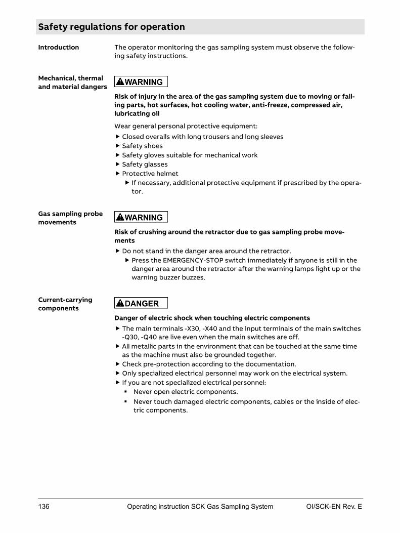
136 Operating instruction SCK Gas Sampling System OI/SCK-EN Rev. E
Safety regulations for operation
The operator monitoring the gas sampling system must observe the follow-ing safety instructions.
Risk of injury in the area of the gas sampling system due to moving or fall-ing parts, hot surfaces, hot cooling water, anti-freeze, compressed air, lubricating oil
Wear general personal protective equipment:
Closed overalls with long trousers and long sleeves Safety shoes Safety gloves suitable for mechanical work Safety glasses Protective helmet If necessary, additional protective equipment if prescribed by the opera-
tor.
Risk of crushing around the retractor due to gas sampling probe move-ments Do not stand in the danger area around the retractor. Press the EMERGENCY-STOP switch immediately if anyone is still in the
danger area around the retractor after the warning lamps light up or the warning buzzer buzzes.
Danger of electric shock when touching electric components The main terminals -X30, -X40 and the input terminals of the main switches
-Q30, -Q40 are live even when the main switches are off. All metallic parts in the environment that can be touched at the same time
as the machine must also be grounded together. Check pre-protection according to the documentation. Only specialized electrical personnel may work on the electrical system. If you are not specialized electrical personnel: Never open electric components. Never touch damaged electric components, cables or the inside of elec-
tric components.
Introduction
Mechanical, thermal and material dangers
Gas sampling probe movements
Current-carrying components

OI/SCK-EN Rev. E Operating instruction SCK Gas Sampling System 137
danger of burning due to hot surfaces during and after operation of the gas sampling system. Do not touch the gas sampling system during and after operation. Do not touch the gas sampling system until it has cooled down to 50 °C.
Specifically, do not touch the cooling module, the heated sample gas line, the connection box for the heated sample gas line on the retractor, the heated sampling filter, the entire gas sampling probe, the metal structure of the retractor, the shutter of the duct opening. If it is unavoidable to touch hot components, wear a face mask against
heat, heat-proof gloves and protective welder's clothing.
Danger of burning due to material falling or spalling off the retracted probe Never enter the danger area around the retractor during operation. Do not approach the retracted probe until it has cooled down. If it is unavoidable to approach the hot probe, wear a face mask against
heat, heat-proof gloves and protective welder's clothing.
Danger due to harmful gases and jet flames in the area of the duct opening while the gas sampling probe is moving in or out Never enter the danger area around the retractor during operation. Ensure adequate ventilation of the work place.
Risk of scalding when hot cooling water escapes from the cooling system in the event of a malfunction Wait until the entire cooling water has been evacuated before approach-
ing.
Hot surfaces
Falling or spalling hot material
Harmful gases, jet flames
Hot cooling water

138 Operating instruction SCK Gas Sampling System OI/SCK-EN Rev. E
Danger of injury to skin and eyes in the event of contact with cooling water or anti-freeze. Avoid contact with the cooling water and the anti-freeze.
Wash any cooling water and anti-freeze off the skin immediately with water and soap.
If cooling water or anti-freeze gets in the eyes despite protective glass-es, rinse them thoroughly under running water, holding the eyelids open.
Observe instructions in the anti-freeze manufacturer's safety data sheet.
Danger due to skin and eye injuries in the event of contact with lubricating oil from the pneumatic box of, from the filter muffler or from inside the pneumatic motor. Avoid contact with lubricating oil.
Wash any lubricating oil off the skin immediately with water and soap.
If any lubricating oil gets in the eyes despite protective glasses, rinse them thoroughly under running water, holding the eyelids open.
Observe instructions in the lubricating oil manufacturer's safety data sheet.
Risk of falling on slippery floor due to escaped or spilled cooling water and lubricating oil or dirt Always keep the floor around the gas sampling system clean and dry.
Harmful anti-freeze
Harmful lubricating oil
Slippery floor

OI/SCK-EN Rev. E Operating instruction SCK Gas Sampling System 139
Monitoring automatic mode
After starting up the gas sampling system you can switch the gas sampling system to automatic mode. Automatic mode allows continuous operation of the system for sample gas sampling. Probe cleaning steps take place after defined intervals (these can be set using the controller).
Observe all safety instructions in the section Safety regulations for operation on page 136 when performing this work.
The following conditions must be met for automatic mode:
Gas sampling probe correctly installed and put into operation. The gas sampling probe is inserted into the kiln.
How to monitor the gas sampling system in automatic mode:
Step Procedure
1 In controller: switch gas sampling probe to automatic mode (if this has not already been done).
Path: Operation ► Automatic on / off
2 In controller: monitor operation of the gas sampling system in the diagnostic screens.
The following parameters are relevant: "Cooling Water Pressure" "Sample Gas Pressure" "Cooling Water Flow Rate" "Cooling Water Flow Temp." "Cooling Water Return Temp." "Probe Heating Temp."
Observe the following rules in automatic mode: In case of error signals: read the message on the
touchscreen immediately and take appropriate action (Er-rors on page 215).
Check general condition of the system (Checking general condition on page 141).
Failure of mains power leads to immediate retraction of the gas sampling probe out of the kiln. After switching the power supply back on, the display and operating unit boots and the sampling system switches to manual mode.
To resume normal measuring operation you must manually insert the gas sampling probe into the kiln and then switch to automatic mode (see section Start-up on page 111).
Introduction
Requirements
Instructions
Power failure
140 Operating instruction SCK Gas Sampling System OI/SCK-EN Rev. E
If the gas sampling probe was installed in accordance with the recommenda-tions in the Installation section and in the project planning documents, ade-quate protection of the probe is guaranteed in operation.
The probe (probe pipe and filter) may nevertheless get damaged, above all in the following situations:
if material falls on the probe of too much material adheres to the probe pipe if tire parts or bullets hit the probe pipe if red-hot material flows over the probe if aggressive combustion residues corrode the probe pipe and filter mate-
rial if the probe pipe material is worn by high flue gas speeds (particularly
critical at flue gas speeds > 20 m/s) The manufacturer offers no warranty for such damage.
The following problems may occur when measuring SO2:
if the gas sampling hole on the tip of the probe clogs up with combustion particles, an increasing amount of SO2 is absorbed,
if a layer of rust particles builds up on the filter unit, SO2 will also be ab-sorbed as the sample gas travels to the analyzer,
if the sample gas condenses in the sample gas tube, part of the SO2 dis-solves in the condensation, which in turn decreases the SO2 concentration measured in the analyzer,
In the above-mentioned cases, the falsification of results will be all the more severe, the lower the concentration of SO2.
Maximum reliability of SO2 measurement is given,
when the gas sampling hole(s) on the probe tips are completely open (i.e. not clogged up with rust particles),
immediately after blow-back. Due to the propensity of rust particles to form incrustations on or inside the gas sampling system that may result in absorption of SO2, the manufacturer offers no warranty on such measurements.
If it can be assumed that safe operation is no longer possible, the sampling system must be taken out of operation and secured against being started up again.
It can be assumed that safe operation is no longer possible:
if the sampling system is visibly seriously damaged, if the sampling system is no longer operational, after prolonged storage under adverse conditions, after severe transport stress.
Damage
SO2 measurement
Safe operation no longer possible

OI/SCK-EN Rev. E Operating instruction SCK Gas Sampling System 141
Checking general condition
Observe all safety instructions in the section Safety regulations for operation on page 136 when performing this work.
When the gas sampling system is in operation, monitor the general condition of the system on a daily basis:
Module Procedure
Retractor in-cluding probe
Check general condition of retractor with regard to the following: general damage missing or loose covers visible damage to electric cables hose and pipe leaks drive chain: chain tension chain link wear
compressed-air oiler damage leaks oil level
gas sampling probe: signs of wear (e.g. polished metal surfaces)
Cooling module Check general condition of cooling module with regard to the following: general damage missing or loose covers visible damage to electric cables hose and pipe leaks
Control cabinet Check general condition of control cabinet with regard to the following: general damage missing or loose covers visible damage to electric cables dripping water or other liquids
Compressed-air tank(optional)
Check general condition of compressed-air tank with regard to the following: visible damage
If there are any defects that impact safety, inform the responsible mainte-nance personnel. If cleaning is necessary, follow the instructions in Checking the condition of the system, cleaning the system on page 163.
Condition of the sampling system

142 Operating instruction SCK Gas Sampling System OI/SCK-EN Rev. E
Check the duct opening for clogging at regular intervals and clean if neces-sary.
Note: Inserting the gas sampling probe when the duct opening is clogged can lead to damage to the probe. The same applies to re-inserting the gas sam-pling probe after prolonged standstill of the sampling system.
Owing to the greater flow speeds in this process, after start-up the gas sam-pling probe must be checked frequently for wear at the calcinator gas outlet measuring point. If distinct signs of wear are visible after a short time, check the installation position of the gas sampling probe. Failing to observe this can lead to severe damage or total loss of the gas sampling probe.
Checking the duct opening
Special case: calcinator gas outlet
OI/SCK-EN Rev. E Operating instruction SCK Gas Sampling System 143
Cleaning gas sampling probe H
Observe all safety instructions in the section Safety regulations for operation on page 136 when performing this work.
You can start a cleaning process as follows:
Clean in MANUAL mode (on touchscreen on the control cabinet) Clean in MANUAL mode (remote control via network connection) Clean in AUTOMATIC mode (time-controlled) Clean in AUTOMATIC mode (error-controlled)
In MANUAL mode you can start the cleaning process in the Cleaning dialog (Operation ► Probe ► Cleaning).
The following two buttons are available:
Button Function
Manual Mechanical Cleaning
The plunger moves forward and backward once to clean the sample gas inlet.
Start Manual Cleaning
The system emits a blast of air lasting 5 seconds to clean the probe filter; the plunger is activated.
Note: In MANUAL mode you can also remote-control cleaning via a network connection.
In AUTOMATIC mode the cleaning process is a time-controlled, automatic process that runs as follows:
Phase Description
1 Plunger moves forward and backward to clean the sample gas inlet. Measuring is not interrupted.
The following processes runs after a number of cleaning cycles, that you can set on the touchscreen:
Phase Description
1 Air cannon activated to clean the wall tube.
2 Gas sampling probe moves out and in to scrape off any adher-ing material.
3 Plunger moves forward and backward to clean the sample gas inlet.
4 Air blast to clean the probe filter.
Starting the cleaning process
Cleaning in MANUAL mode
Cleaning in AUTOMATIC mode

144 Operating instruction SCK Gas Sampling System OI/SCK-EN Rev. E
Note: The following function is available only when SCK is connected to the ACX analysis system. When used with other analysis systems, a default sam-ple gas probe pressure of "9999 hPa" is indicated in the "Diagnosis" menu.
In AUTOMATIC mode the following cleaning procedure is performed when the Sample Gas Probe Pressure MIN error message is displayed:
Phase Description
1 Plunger moves forward and backward to clean the sample gas inlet.
This cleaning cycle is repeated up to three times. If this does not remedy the error, error message Error 3x Cleaning Not Successful Probe H is displayed and the gas sampling system switches to error mode. The probe is retracted out of the kiln. No more cleaning processes and movements take place. See Errors on page 215 section for further details.
Cleaning parameters such as the time between cleaning cycles are delivered as default settings with the gas sampling system (Default operating parame-ter settings on page 48). You can modify them in operation to suit local re-quirements and specific fuels (see Optimizing operating parameters on page 51).
Cleaning in the event of error message
Configuring cleaning

OI/SCK-EN Rev. E Operating instruction SCK Gas Sampling System 145
Cleaning gas sampling probe 60S
Observe all safety instructions in the section Safety regulations for operation on page 136 when performing this work.
You can start a cleaning process as follows:
Clean in MANUAL mode (on touchscreen on the control cabinet) Clean in MANUAL mode (remote control via network connection) Clean in AUTOMATIC mode (time-controlled) Clean in AUTOMATIC mode (error-controlled)
In MANUAL mode you can start the cleaning process by pressing the Manual Cleaning button in the Cleaning dialog (Operation ► Probe 60 ► Cleaning).
The cleaning process runs as follows:
Phase Description
1 Two air blasts lasting 1 second each to clean the probe filter.
2 Two air blasts lasting 1 second each to clean the filter casing.
3 One air blast lasting 3 seconds to clean the probe pipe.
Note: In MANUAL mode you can also remote-control cleaning via a network connection.
In AUTOMATIC mode the cleaning process is a time-controlled, automatic process that runs as follows:
Phase Description
1 Two air blasts lasting 1 second each to clean the probe filter.
2 Two air blasts lasting 1 second each to clean the filter casing.
3 One air blast lasting 3 seconds to clean the probe pipe.
The following processes runs after a number of cleaning cycles, that you can set on the touchscreen:
Phase Description
1 Air cannon activated to clean the wall tube.
2 Gas sampling probe moves out and in to scrape off any adher-ing material.
3 Two air blasts lasting 1 second each to clean the probe filter.
4 Three air blasts lasting 1 second each to clean the filter casing.
5 Air blast lasting 3 seconds to clean the probe pipe.
Starting the cleaning process
Cleaning in MANUAL mode
Cleaning in AUTOMATIC mode

146 Operating instruction SCK Gas Sampling System OI/SCK-EN Rev. E
Note: The following function is available only when SCK is connected to the ACX analysis system. When used with other analysis systems, a default sam-ple gas probe pressure of "9999 hPa" is indicated in the "Diagnosis" menu.
In AUTOMATIC mode the following cleaning procedure is performed when the Sample Gas Probe Pressure MIN error message is displayed:
Phase Description
1 Two air blasts lasting 1 second each to clean the probe filter.
2 Two air blasts lasting 1 second each to clean the filter casing.
3 One air blast lasting 3 seconds to clean the probe pipe.
This cleaning cycle is repeated up to three times. If this does not remedy the error, error message Error 3x Cleaning Not Successful Probe 60S is displayed and the gas sampling system switches to error mode. The probe is retracted out of the kiln. No more cleaning processes and movements take place. See Errors on page 215 section for further details.
Cleaning parameters such as the time between cleaning cycles are delivered as default settings with the gas sampling system (Default operating parame-ter settings on page 48). You can modify them in operation to suit local re-quirements and specific fuels (see Optimizing operating parameters on page 51).
Cleaning in the event of error message
Configuring cleaning

OI/SCK-EN Rev. E Operating instruction SCK Gas Sampling System 147
Using the EMERGENCY-STOP switch
Observe all safety instructions in the section Safety regulations for operation on page 136 when performing this work.
The EMERGENCY STOP switch is used to interrupt probe movement immedi-ately in the event of danger to personnel. Actuating the switch disables all mechanisms serving to protect the gas sampling probe. The gas sampling probe interrupts its movement immediately and in any position.
The EMERGENCY STOP switch is used to interrupt probe movement in the event of danger to personnel. The probe is only retracted out of the rotary kiln after pressing the service switch.
What to do after pressing the EMERGENCY STOP switch:
Step Procedure
1 Remove danger.
2 Make sure that the danger cannot occur again, no-one is standing in the area of probe retractor travel.
3 Unlock the EMERGENCY STOP switch by turning the back ring in the direction of the arrow.
4 Actuate service switch in control cabinet (i.e. turn to ON posi-
tion).
WARNING! Actuating the service switch moves the probe out of the kiln. Do not stand in the area of travel of the probe or probe carriage until the probe has reached its end position and the warning lamps go out.
Result: The gas sampling probe is automatically retracted out of the kiln, the controller displays the Maintenance message.
5 Turn service switch back to the initial position (OFF).
Introduction
Instructions

OI/SCK-EN Rev. E Operating instruction SCK Gas Sampling System 149
Chapter 9 Maintenance
Topic Page Maintenance plan ............................................................................................... 150
Equipment layout plan ...................................................................................... 154
Acquiring spare parts and wear parts ............................................................ 157
Safety regulations for maintenance work ..................................................... 158
Operating the service switch ........................................................................... 161
Checking the condition of the system, cleaning the system ..................... 163
Evaluating trend displays ................................................................................. 166
Checking the residual current circuit breaker............................................... 167
Checking protective installations ................................................................... 169
Checking for leaks .............................................................................................. 173
Gas sampling probe H: Removing incrustations .......................................... 176
Gas sampling probe H: Replacing the intake filter ...................................... 178
Gas sampling probe H: Replacing membrane pump membranes ............ 181
Gas sampling probe 60S: Removing incrustations ...................................... 184
Gas sampling probe 60S: Cleaning or replacing the outlet filter .............. 186
Gas sampling probe 60S: Replacing the seal set ......................................... 189
Probe retractor: Checking filter/pressure control combination ............... 191
Probe retractor: Checking and replacing the filter muffler ........................ 193
Probe retractor: Checking and topping up the oiler .................................... 195
Probe retractor: Checking and tightening the drive chain ......................... 198
Probe retractor: Checking and, if necessary, adjusting the position of the probe ....................................................................................... 200
Probe retractor: Checking and, if necessary, adjusting the position indicator (probe end position) ....................................................... 204
Probe retractor: Checking the bellows ........................................................... 207
Cooling module: Vent the cooling-water circuit .......................................... 208
Cooling module: Checking and topping up cooling water ......................... 210
Pneumatic system: Replacing the compressed-air filter ............................ 213

150 Operating instruction SCK Gas Sampling System OI/SCK-EN Rev. E
Maintenance plan
This section gives an overview of maintenance work to be performed at regu-lar intervals. The tasks described here require special training and under some circumstances involve working on control cabinet open and powered on. They must therefore only be carried out by qualified and specially trained persons.
If it can be assumed that safe operation is no longer possible, the gas sam-pling system must be taken out of operation and secured against being start-ed up again unintentionally.
It can be assumed that safe operation is no longer possible:
if the gas sampling system is visibly damaged, if a check reveals problems, if the gas sampling system no longer works, after prolonged storage in adverse conditions, after severe transport stress.
It is recommended to have the gas sampling system maintained by the ABB representative responsible for you.
When performing maintenance work on the gas sampling system, the service switch must be in the ON position with a few exceptions (for example, when checking the EMERGENCY STOP switch). Actuating the service switch auto-matically retracts the gas sampling probe out of the kiln, and the controller displays the Maintenance message. See Chapter Operating the service switch on page 161 for more details.
You can secure the service switch with a padlock to prevent unintentionally restarting the gas sampling system.
Introduction
Service switch
Unintentional restart

OI/SCK-EN Rev. E Operating instruction SCK Gas Sampling System 151
The following tables show the maintenance intervals within which to perform maintenance work, with a link to the relevant instructions:
Maintenance task See … Inspection/Maintenance intervall
as r
equi
red
day
iy
wee
kly
twic
e ye
arly
year
ly
ever
y 2
year
s
General tasks
Check the system and clean if necessary
Checking the condition of the system, cleaning the system on page 163
X
Display and evaluate trend displays
Evaluating trend displays on page 166 X
Functional test of residual current circuit breaker
Checking the residual current circuit breaker on page 167
X
Functional tests of: EMERGENCY STOP
switch Warning lamps Warning buzzer external warning horn (op-
tional)
Checking protective installations on page 169
X
Maintenance task See … Inspection/Maintenance intervall
as r
equi
red
day
iy
wee
kly
twic
e ye
arly
year
ly
ever
y 2
year
s
Gas sampling probe H
Mechanical cleaning of probe pipe and tip
Gas sampling probe H: Removing incrustations on page 176
X X
Replace intake filter Gas sampling probe H: Replacing the intake filter on page 178
X X
Replace membrane pump membranes
Gas sampling probe H: Replacing membrane pump membranes on page 181
X
Maintenance plan

152 Operating instruction SCK Gas Sampling System OI/SCK-EN Rev. E
Maintenance task See … Inspection/Maintenance intervall
as r
equi
red
day
iy
wee
kly
twic
e ye
arly
year
ly
ever
y 2
year
s
Gas sampling probe 60S Mechanical cleaning of
probe pipe and tip Gas sampling probe 60S: Removing incrustations on page 184
X X
Clean or replace outlet filter Gas sampling probe 60S: Cleaning or replacing the outlet filter on page 186
X X
Replace O-ring seals on the filter unit
Gas sampling probe 60S: Replacing the seal set on page 189
X
Maintenance task See … Inspection/Maintenance intervall
as r
equi
red
day
iy
wee
kly
twic
e ye
arly
year
ly
ever
y 2
year
s
Probe retractor Check filter muffler Probe retractor: Checking and replac-
ing the filter muffler on page 193 X
Check oil level in oiler in pneumatic box and chang-ing the quantity of oil deliv-ered
Probe retractor: Checking and topping up the oiler on page 195
X
Check and if necessary tighten drive chain
Probe retractor: Checking and tighten-ing the drive chain on page 198
X X
Check and if necessary adjust the filter/pressure control combination or re-place filter
Probe retractor: Checking fil-ter/pressure control combination on page 191
X
Check condition of bellows Probe retractor: Checking the bellows on page 207
X
Check and, if necessary, adjust the position of the probe
Probe retractor: Checking and, if nec-essary, adjusting the position of the probe on page 200
X
Check position indicator on the retractor and, if neces-sary, re-align
Probe retractor: Checking and, if nec-essary, adjusting the position indica-tor (probe end position) on page 204
X X

OI/SCK-EN Rev. E Operating instruction SCK Gas Sampling System 153
Maintenance task See … Inspection/Maintenance intervall
as r
equi
red
day
iy
wee
kly
twic
e ye
arly
year
ly
ever
y 2
year
s
Cooling module Check cooling water, top up
if necessary Cooling module: Checking and top-ping up cooling water on page 210
X
Vent the cooling-water circuit
Cooling module: Venting the cooling-water circuit on page 208
X X
Check cooling-water sys-tem for leaks
Checking for leaks on page 173 X
Maintenance task See … Inspection/Maintenance intervall
as r
equi
red
day
iy
wee
kly
twic
e ye
arly
year
ly
ever
y 2
year
s
Pneumatic system Replace compressed-air
filter in pneumatic box Pneumatic system: Replacing the compressed-air filter on page 213
X
Check compressed-air system for leaks
Checking for leaks on page 173 X

154 Operating instruction SCK Gas Sampling System OI/SCK-EN Rev. E
Equipment layout plan
Diagram of the location of maintenance-relevant equipment on the retractor (detailed view of pneumatic box below):
The following table lists the above-mentioned equipment:
Equipment ID Designation
-J53 Filter/pressure control combination
-J54 Compressed-air gate valve
-J74 Pneumatic motor oiler
-J75 EMERGENCY-STOP switch for probe movement
-J77 Pneumatic valve "Insert probe"
-J78 Pneumatic valve "Retract probe"
-J79 Pneumatic valve "shutter"
-J81 Pneumatic motor
-J82 Gate valve
-J83 Air filter
-P71 Probe movement warning lamp
-P72 Probe movement warning lamp
not illustrated Position indicators -B71, -B72, -S72
Illustration
Equipment
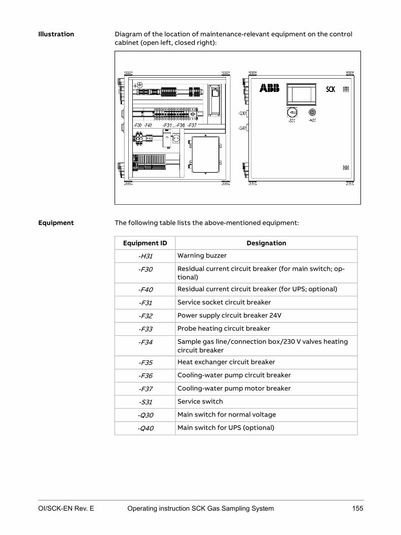
OI/SCK-EN Rev. E Operating instruction SCK Gas Sampling System 155
Diagram of the location of maintenance-relevant equipment on the control cabinet (open left, closed right):
The following table lists the above-mentioned equipment:
Equipment ID Designation
-H31 Warning buzzer
-F30 Residual current circuit breaker (for main switch; op-tional)
-F40 Residual current circuit breaker (for UPS; optional)
-F31 Service socket circuit breaker
-F32 Power supply circuit breaker 24V
-F33 Probe heating circuit breaker
-F34 Sample gas line/connection box/230 V valves heating circuit breaker
-F35 Heat exchanger circuit breaker
-F36 Cooling-water pump circuit breaker
-F37 Cooling-water pump motor breaker
-S31 Service switch
-Q30 Main switch for normal voltage
-Q40 Main switch for UPS (optional)
Illustration
Equipment

156 Operating instruction SCK Gas Sampling System OI/SCK-EN Rev. E
Diagram of location of maintenance-relevant equipment on cooling module:
The following table lists the above-mentioned equipment:
No. Designation
1 Shut-off valve cooling water -J63
2 Cooling water inlet
3 Cooling water feed
4 Safety relief valve outlet
5 Heat exchanger -J60
6 Cooling water return
Illustration
Equipment
OI/SCK-EN Rev. E Operating instruction SCK Gas Sampling System 157
Acquiring spare parts and wear parts
To order spare parts or to order service, please contact your local ABB service partner or:
ABB Service Phone: +49 (0)69 7930 4706 Fax: +49 (0)69 7930 4707 Email: [email protected]
Service

158 Operating instruction SCK Gas Sampling System OI/SCK-EN Rev. E
Safety regulations for maintenance work
Maintenance personnel must observe the following safety instructions when performing maintenance work.
Risk of injury in the area of the gas sampling system due to moving or fall-ing parts, hot surfaces, hot cooling water, anti-freeze, compressed air, lubricating oil
Wear general personal protective equipment:
Closed overalls with long trousers and long sleeves Safety shoes Safety gloves suitable for mechanical work Safety glasses Protective helmet If necessary, additional protective equipment if prescribed by the opera-
tor.
Danger of crushing when lifting or lowering the transport unit Only appropriately trained personnel may transport the transport units and
only with the aid of the recommended transport equipment. Do not stand under suspended loads. Follow the transport instructions in these operating instructions care-
fully.
Risk of crushing around the retractor due to gas sampling probe move-ments Before commencing any work on the gas sampling system, turn the service
switch to "ON" and secure the service switch against unauthorized switch-ing (with a padlock).
Additionally press the EMERGENCY-STOP switch before working on the retractor or probe.
Do not enter the danger area around the retractor until it is at standstill and the warning lamps and buzzer are off.
Never stand in the danger area around the retractor when the protective installation is closed.
When the warning lamps light up or the earning buzzer buzzes, leave the danger area around the probe retractor immediately as the probe is about to move at any moment. Press the EMERGENCY-STOP switch immediately if anyone is still in the
danger area around the retractor after the warning lamps light up or the warning buzzer buzzes.
Introduction
Mechanical, thermal and material dangers
Heavy transport units
Gas sampling probe movements

OI/SCK-EN Rev. E Operating instruction SCK Gas Sampling System 159
Danger of electric shock when working on electric components Only specialized electrical personnel may work on the electrical system. Disconnect the gas sampling system from the power supply before work-
ing on the electrical components. Observe national regulations pertaining to electrical equipment.
The main terminals -X30, -X40 and the input terminals of the main switches -Q30, -Q40 are live even when the main switches are off.
All metallic parts in the environment that can be touched at the same time as the machine must also be grounded together.
Check pre-protection according to the documentation.
Danger of burning due to hot surfaces during and after operation of the gas sampling system Do not touch the gas sampling system during and after operation. Do not touch the gas sampling system until it has cooled down to 50 °C.
Specifically, do not touch the cooling module, the heated sample gas line, the connection box for the heated sample gas line on the retractor, the heated sampling filter, the entire gas sampling probe, the metal structure of the retractor, the shutter of the duct opening. If it is unavoidable to touch hot components, wear a face mask against
heat, heat-proof gloves and protective welder's clothing.
Danger of burning due to material falling or spalling off the retracted probe Never enter the danger area around the retractor during operation. Do not approach the retracted probe until it has cooled down. If it is unavoidable to approach the hot probe, wear a face mask against
heat, heat-proof gloves and protective welder's clothing.
Danger due to harmful gases from the rotary kiln and jet flames in the area of the shutter, particularly while the gas sampling probe is moving in and out Ensure adequate ventilation of the work place. Only enter the danger area around the retractor when the shutter is closed. If work is unavoidable in the area of the duct opening, lock the shutter
before commencing work and wear respiratory protection.
Current-carrying components
Hot surfaces
Falling or spalling hot material
Harmful gases, jet flames
160 Operating instruction SCK Gas Sampling System OI/SCK-EN Rev. E
Risk of scalding due to hot cooling water when working on the cooling-water circuit, above all on drain valves and screw connections Do not perform work on the cooling water circuit until the gas sampling
system has cooled down.
Danger of injury to skin and eyes in the event of contact with cooling water or anti-freeze Avoid contact with the cooling water and the anti-freeze.
Wash any cooling water and anti-freeze off the skin immediately with water and soap.
If cooling water or anti-freeze gets in the eyes despite protective glass-es, rinse them thoroughly under running water, holding the eyelids open.
Observe instructions in the anti-freeze manufacturer's safety data sheet.
Danger due to skin and eye injuries in the event of contact with lubricating oil from the pneumatic box of, from the filter muffler or from inside the pneumatic motor Avoid contact with lubricating oil.
Wash any lubricating oil off the skin immediately with water and soap.
If any lubricating oil gets in the eyes despite protective glasses, rinse them thoroughly under running water, holding the eyelids open.
Observe instructions in the lubricating oil manufacturer's safety data sheet.
Danger due to harmful dusts when cleaning the gas sampling system Wear a dust mask when cleaning. Wash any dust off the skin immediately with water and soap.
Risk of falling on slippery floor due to escaped or spilled cooling water and lubricating oil or dirt Always keep the floor around the gas sampling system clean and dry.
Hot cooling water
Harmful anti-freeze
Harmful lubricating oil
Harmful dusts
Slippery floor

OI/SCK-EN Rev. E Operating instruction SCK Gas Sampling System 161
Operating the service switch
The service switch puts the system into maintenance mode. If work described in the following maintenance instructions must be performed in maintenance mode, proceed as follows.
Always take the following safety measures when performing this work:
Wear the general protective equipment.
Before commencing any work on the gas sampling system, turn the ser-vice switch to ON and secure the service switch against unauthorized switching (with a padlock).
Additionally press the EMERGENCY-STOP switch before working on the retractor or probe.
Do not enter the danger area around the retractor until it is at standstill and the warning lamps and buzzer are off.
Never stand in the danger area around the retractor when the protective installation is closed.
When the warning lamps light up or the earning buzzer buzzes, leave the danger area around the probe retractor immediately as the probe is about to move at any moment.
Press the EMERGENCY-STOP switch immediately if anyone is still in the danger area around the retractor after the warning lamps light up or the warning buzzer buzzes.
Explanation of safety measures: Safety regulations for maintenance work on page 158.
The service switch is in the OFF position.
Meaning
Safety measures
Requirement

162 Operating instruction SCK Gas Sampling System OI/SCK-EN Rev. E
How to put the system into maintenance mode:
Step Procedure
1 Make sure that no-one is standing in the area of probe retrac-tor travel.
2 On the control cabinet: Turn service switch -S31 (1) clockwise to the ON position.
WARNING! Actuating the service switch moves the probe out of the kiln. Do not stand in the area of travel of the probe or probe carriage until the probe has reached its end position and the warning lamps go out.
Result: The gas sampling probe is automatically retracted out of the kiln; the controller displays the Maintenance message.
3 Secure the service switch against unauthorized actuation.
4 When working on the retractor and gas sampling probe, addi-tionally actuate the EMERGENCY-STOP switch for reasons of safety.
5 Perform maintenance tasks.
6 Leave danger area around the retractor and close the protec-tive installation.
7 Turn service switch -S31 counter-clockwise to the OFF position.
8 Re-insert the probe using the controller.
Path:Operation ► Probe ► Probe Action ► Insert
WARNING! The probe moves into the kiln. Do not stand in the area of travel of the probe or probe carriage.
Instructions

OI/SCK-EN Rev. E Operating instruction SCK Gas Sampling System 163
Checking the condition of the system, cleaning the system
Check the condition of the gas sampling system at regular intervals; in the event of safety-relevant defects, inform the responsible maintenance person-nel. If you observe any unusual noises, follow the recommendations in Errors on page 215.
If necessary, submit the gas sampling system to rough cleaning. Special at-tention should be given to the following:
dust under covers and in connection boxes excessive dirt on the surface of the modules excessive soiling of the runner in the probe retractor heat exchanger cooling fins
daily
Always take the following safety measures when performing the work de-scribed below:
Wear the general protective equipment.
Turn the service switch to ON and secure the service switch against un-authorized switching (with a padlock).
Additionally press the EMERGENCY STOP switch.
Do not enter the danger area around the retractor until it is at standstill and the warning lamps and buzzer are off and the shutter is closed.
Do not touch the gas sampling system until it has cooled down to 50 °C.
Do not approach the retracted probe until it has cooled down.
Always keep the floor around the gas sampling system clean and dry.
When performing any cleaning work:
Wear a dust mask when cleaning.
Wash any dust off the skin immediately with water and soap.
Ensure adequate ventilation of the work place.
Checking and cleaning the probe retractor:
If work is unavoidable in the area of the duct opening, lock the shutter before commencing work and wear respiratory protection.
Avoid contact with lubricating oil. Wash any lubricating oil off the skin immediately with water and soap.
If any lubricating oil gets in the eyes despite protective glasses, rinse them thoroughly under running water, holding the eyelids open.
Observe instructions in the lubricating oil manufacturer's safety data sheet.
Meaning
Maintenance interval
Safety measures

164 Operating instruction SCK Gas Sampling System OI/SCK-EN Rev. E
Checking the duct opening:
Preferably check and clean the duct opening when the rotary kiln is out of operation. If you clean the duct opening when the rotary kiln is in operation. Wear a face mask against heat, heat-proof gloves and protective weld-
er's clothing and respiratory protection against toxic gases. Keep the time in which the feedthrough opening is open as short as
possible. Checking and cleaning the cooling module:
Do not perform work on the cooling water circuit until the gas sampling system has cooled down.
Avoid contact with the cooling water and the anti-freeze.
Wash any cooling water and anti-freeze off the skin immediately with water and soap.
If cooling water or anti-freeze gets in the eyes despite protective glass-es, rinse them thoroughly under running water, holding the eyelids open.
Observe instructions in the anti-freeze manufacturer's safety data sheet.
Explanation of safety measures: Safety regulations for maintenance work on page 158.
The following conditions must be met:
The service switch is in the ON position, the gas sampling probe is com-pletely retracted from the kiln (see Operating the service switch on page 161).
The service switch is secured against unauthorized actuation. The gas sampling system has cooled down. The EMERGENCY STOP switch is pressed.
Perform the following steps for the control cabinet:
Step Procedure 1 Check general condition of control cabinet with regard to the
following: general damage missing or loose covers visible damage to connection cables
2 Check control cabinet for dripping water or other liquids.
3 In the event of excessive soiling of the surface of the control cabinet, clean with a soft brush or compressed-air.
4 Clean touchscreen, particularly edge areas, with compressed-air and/or moist cloth (if you use cleaning agents, you can request a resistance table from ABB Service).
Requirements
Checking and cleaning the control cabinet:

OI/SCK-EN Rev. E Operating instruction SCK Gas Sampling System 165
Perform the following steps for the probe retractor:
Step Procedure 1 Check general condition of retractor with regard to the follow-
ing: general damage missing or loose covers visible damage to electric cables
2 Check hoses and pipes for leaks 3 In the event of excessive soiling of the surface of the retractor,
clean with a soft brush or compressed-air; treat rollers in the same way.
4 Check condition of drive chain with regard to the following: chain tension chain link wear
5 In pneumatic box: Check compressed-air oiler for the following: damage leaks oil level
6 Check compressed-air tank (if present) for visible damage. 7 Check probe pipe for signs of wear, e.g. polished metal surfac-
es. This applies particularly after start-up, after changing the alignment of the probe, etc. The calcinator outlet measuring point is particularly affected. If you observe signs of wear, you must reposition the gas sam-pling probe in the process gas flow; if you have any questions regarding repositioning the probe, contact ABB Service.
Check the wall tube for clogging and deposits at regular intervals and clean if necessary.
Note: Inserting the gas sampling probe when the wall tube is clogged can lead to damage to the probe. The same applies to re-inserting the gas sampling probe after prolonged standstill of the gas sampling system.
Perform the following steps for the cooling module:
Step Procedure 1 Check general condition of cooling module with regard to the
following: general damage missing or loose covers visible damage to connection cables
2 Check hoses and pipes for leaks 3 In the event of excessive soiling of the surface of the cooling
module, or after one week at the latest, clean with a soft brush or compressed-air.
4 Clean motor casing with compressed air.
5 Clean cooling fins with dry compressed air (accessible at the back of the heat exchanger).
6 Check cooling module environment for any materials that can fly around easily.
Checking and cleaning the probe retractor
Checking the duct opening
Checking and cleaning the cooling module

166 Operating instruction SCK Gas Sampling System OI/SCK-EN Rev. E
Evaluating trend displays
Irregularities of cooling-water pressure, cooling-water flow rate and cooling-water temperature may indicate various errors. Common reasons for an in-crease or drop in measured values may be, for example, a clogged filter, in-crustations on the gas sampling probe, inadequate cooling of the heat ex-changer or inadequate delivery rate of the cooling-water pump.
Displaying trend displays requires an access level 2 password.
Perform the following steps to evaluate trend displays:
Step Procedure 1 Open the Trends submenu.
Path: Diagnosis ► Trends
2 Select one of the available parameters: "Sample Gas Pressure" "Cooling Water Pressure" "Cooling Water Flow Rate" "Cooling Water Flow Temp." "Cooling Water Return Temp."
3 A typical trend screen is displayed:
The measured value is blue, alarm thresholds are also high-lighted with a special color: Pre-alarm (maintenance required): yellow Main alarm (error): red The reading rule indicates the measured value at the specific time. A zoom function allows you to zoom in on details. For further details refer to section Description of control system on page 35.
Meaning
Requirements
Instructions
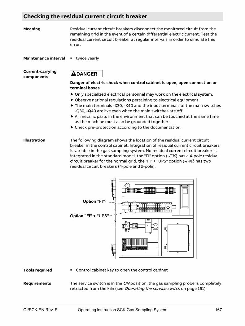
OI/SCK-EN Rev. E Operating instruction SCK Gas Sampling System 167
Checking the residual current circuit breaker
Residual current circuit breakers disconnect the monitored circuit from the remaining grid in the event of a certain differential electric current. Test the residual current circuit breaker at regular intervals in order to simulate this error.
twice yearly
Danger of electric shock when control cabinet is open, open connection or terminal boxes Only specialized electrical personnel may work on the electrical system. Observe national regulations pertaining to electrical equipment. The main terminals -X30, -X40 and the input terminals of the main switches
-Q30, -Q40 are live even when the main switches are off. All metallic parts in the environment that can be touched at the same time
as the machine must also be grounded together. Check pre-protection according to the documentation.
The following diagram shows the location of the residual current circuit breaker in the control cabinet. Integration of residual current circuit breakers is variable in the gas sampling system. No residual current circuit breaker is integrated in the standard model, the "FI" option (-F30) has a 4-pole residual circuit breaker for the normal grid, the "FI" + "UPS" option (-F40) has two residual circuit breakers (4-pole and 2-pole).
Control cabinet key to open the control cabinet
The service switch is in the ON position; the gas sampling probe is completely retracted from the kiln (see Operating the service switch on page 161).
Meaning
Maintenance interval
Current-carrying components
Illustration
Tools required
Requirements
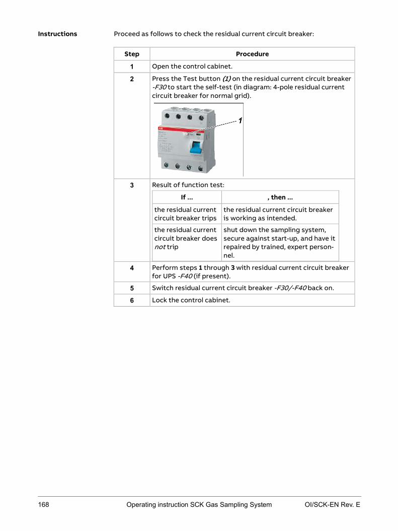
168 Operating instruction SCK Gas Sampling System OI/SCK-EN Rev. E
Proceed as follows to check the residual current circuit breaker:
Step Procedure
1 Open the control cabinet.
2 Press the Test button (1) on the residual current circuit breaker -F30 to start the self-test (in diagram: 4-pole residual current circuit breaker for normal grid).
3 Result of function test:
If ... , then ...
the residual current circuit breaker trips
the residual current circuit breaker is working as intended.
the residual current circuit breaker does not trip
shut down the sampling system, secure against start-up, and have it repaired by trained, expert person-nel.
4 Perform steps 1 through 3 with residual current circuit breaker for UPS -F40 (if present).
5 Switch residual current circuit breaker -F30/-F40 back on.
6 Lock the control cabinet.
Instructions

OI/SCK-EN Rev. E Operating instruction SCK Gas Sampling System 169
Checking protective installations
at least once a year EMERGENCY STOP switch: The EMERGENCY STOP switch -J75 should be checked after shutting down the kiln if possible, as the test procedure disa-bles all monitoring mechanisms. If it is necessary to check during operation, the retracting probe retractor must be max. one meter from the rear end position when you actuate the EMERGENCY STOP switch -J75 in order to prevent uncontrolled heat-up of the probe tip if an error occurs at the same time.
Observe company regulations with regard to maintenance intervals.
Always take the following safety measures when performing this work:
Wear the general protective equipment.
Press the EMERGENCY STOP switch immediately if anyone is still in the danger area around the retractor after the warning lamps light up or the warning buzzer buzzes.
Explanation of safety measures: Safety regulations for maintenance work on page 158.
The following conditions must be met:
System is in operation. Gas sampling probe is inserted into the kiln. Service switch is in the OFF position.
Maintenance interval
Safety measures
Requirements

170 Operating instruction SCK Gas Sampling System OI/SCK-EN Rev. E
Proceed as follows to check the EMERGENCY STOP switch -J75 (note: two people should perform this procedure):
Step Procedure 1 Switch system to manual mode on the touchscreen (if this has
not already been done). Path: Operation ► Automatic on / off
2 Retract gas sampling probe out of the kiln. Path: Operation ► Probe ► Probe Action ► Retract WARNING! Actuating the service switch moves the probe to its end position. Do not stand in the area of travel of the probe or probe carriage until the probe has reached its end position.
3 When the probe is one meter from the rear end position: Press EMERGENCY STOP switch -J75. Target requirement: The probe retractor must interrupt movement immediately.
4 Unlock EMERGENCY STOP switch -J75 by turning the back ring in the direction of the arrow.
5 Turn service switch -S31 on the control cabinet to the ON posi-
tion. WARNING! Actuating the service switch moves the probe to its rear end position. Do not stand in the area of travel of the probe or probe carriage until the probe has reached its end position. Result: The gas sampling probe is retracted to its rear end position, the controller displays the Maintenance message.
6 Turn service switch -S31 back to the initial position (OFF). 7 In the event of irregularities, shut down the sampling system,
secure against start-up (e.g. with a padlock), and have it re-paired by trained, expert personnel.
8 If a second EMERGENCY STOP switch is present, perform these instructions analogously for this switch.
9 Turn service switch back to OFF position and insert gas sam-pling probe again using the controller. WARNING! Gas sampling probe moves into the kiln. Do not stand in the area of travel of the gas sampling probe or probe carriage until the probe is completely inserted into the kiln and the warning lamps go out.
Instructions: checking the EMERGENCY STOP switch

OI/SCK-EN Rev. E Operating instruction SCK Gas Sampling System 171
Perform the following steps to check warning lamps -P71 and -P72:
Step Procedure 1 Switch system to manual mode on the touchscreen (if this has
not already been done). Path: Operation ► Automatic on / off
2 Retract gas sampling probe out of the kiln. Path: Operation ► Probe ► Probe Action ► Retract WARNING! The probe is retracted. Do not stand in the area of travel of the probe or probe carriage until the probe has reached its end position. Target requirement: Warning lamps -P71 and -P72 on the retractor light up immedi-ately.
3 In the event of irregularities, shut down the sampling system, secure against start-up (e.g. with a padlock), and have it re-paired by trained, expert personnel. If they are working as intended: Turn service switch back to OFF position and insert gas sam-pling probe again using the controller. WARNING! Gas sampling probe moves into the kiln. Do not stand in the area of travel of the gas sampling probe or probe carriage until the probe is completely inserted into the kiln and the warning lamps go out.
Perform the following steps to check the warning buzzer -H31:
Step Procedure 1 Switch system to manual mode on the touchscreen (if this has
not already been done). Path: Operation ► Automatic on / off
2 Retract gas sampling probe out of the kiln. Path: Operation ► Probe ► Probe Action ► Retract WARNING! The probe is retracted. Do not stand in the area of travel of the probe or probe carriage until the probe has reached its end position. Target requirement: Warning buzzer -H31 on the control cabinet buzzes.
3 In the event of irregularities, shut down the sampling system, secure against start-up (e.g. with a padlock), and have it re-paired by trained, expert personnel. If they are working as intended: Turn service switch back to OFF position and insert gas sam-pling probe again using the controller. WARNING! Gas sampling probe moves into the kiln. Do not stand in the area of travel of the gas sampling probe or probe carriage until the probe is completely inserted into the kiln and the warning lamps go out.
Instructions: checking warning lamps
Instructions: checking warning buzzers

172 Operating instruction SCK Gas Sampling System OI/SCK-EN Rev. E
Perform the following steps to check the additional warning horn (provided by customer):
Step Procedure 1 Switch system to manual mode on the touchscreen (if this has
not already been done). Path: Operation ► Automatic on / off
2 Retract gas sampling probe out of the kiln. Path: Operation ► Probe ► Probe Action ► Retract Target requirement: The warning horn goes off.
3 In the event of irregularities, shut down the sampling system, secure against start-up (e.g. with a padlock), and have it re-paired by trained, expert personnel. If they are working as intended: Turn service switch back to OFF position and insert gas sam-pling probe again using the controller. WARNING! Gas sampling probe moves into the kiln. Do not stand in the area of travel of the gas sampling probe or probe carriage until the probe is completely inserted into the kiln and the warning lamps go out.
Instructions: checking the additional warning horn

OI/SCK-EN Rev. E Operating instruction SCK Gas Sampling System 173
Checking for leaks
Sample gas paths, the compressed-air system and cooling-water circuit must be checked for leaks on a regular basis.
twice yearly as required in the following cases: Sample gas paths: additionally after opening sample gas lines inside
the connected analyzer cabinet Cooling-water circuit: additionally when pressure in the cooling-water
circuit drops frequently Compressed-air system: additionally when pressure drops in the com-
pressed-air system without any cleaning process or probe retractor movement taking place.
Always take the following safety measures when performing this work:
Wear the general protective equipment.
Turn the service switch to ON and secure the service switch against un-authorized switching (with a padlock).
Additionally press the EMERGENCY STOP switch.
Do not enter the danger area around the retractor until it is at standstill and the warning lamps and buzzer are off and the shutter is closed.
Do not perform the work until the gas sampling system has cooled down.
Avoid contact with the cooling water and the anti-freeze.
Wash any cooling water and anti-freeze off the skin immediately with water and soap.
If cooling water or anti-freeze gets in the eyes despite protective glass-es, rinse them thoroughly under running water, holding the eyelids open.
Observe instructions in the anti-freeze manufacturer's safety data sheet.
Avoid contact with lubricating oil.
Wash any lubricating oil off the skin immediately with water and soap.
If any lubricating oil gets in the eyes despite protective glasses, rinse them thoroughly under running water, holding the eyelids open.
Observe instructions in the lubricating oil manufacturer's safety data sheet.
Always keep the floor around the gas sampling system clean and dry.
Explanation of safety measures: Safety regulations for maintenance work on page 158.
The following tools are required:
For checking the compressed-air system and cooling-water circuit for leaks: leak detection spray
Meaning
Maintenance interval
Safety measures
Required tools

174 Operating instruction SCK Gas Sampling System OI/SCK-EN Rev. E
How to check the sample gas paths up to the sample gas pump:
Step Procedure 1 Switch service switch to ON position (see Operating the service
switch on page 161), press EMERGENCY STOP switch and allow gas sampling system to cool down. WARNING! Risk of burning in the event of contact with compo-nents that are still hot. Do not touch components until they have cooled down to below 50 °C.
2 Detach probe-side connection of sample gas path and seal. 3 Detach analyzer -side connection and fit a tee with shut-off
valve. 4 Connect a U-tube manometer half filled with water to the open
outlet of the tee. 5 Blow nitrogen or air through the shut-off valve to a positive
pressure of 100 hPa (= 1000 mm water column). 6 Close the shut-off valve. Pressure should not change noticeably
within one minute (pressure drop < 1 hPa). A greater pressure drop indicates a leak.
7 After fixing any leaks, refit the sample gas lines. 8 Turn service switch back to OFF position and insert gas sam-
pling probe again using the controller. WARNING! Gas sampling probe moves into the kiln. Do not stand in the area of travel of the gas sampling probe or probe carriage until the probe is completely inserted into the kiln and the warning lamps go out.
How to check the compressed-air system for leaks:
Step Procedure 1 Switch service switch to ON position (see Operating the service
switch on page 161), press EMERGENCY STOP switch and allow gas sampling system to cool down. WARNING! Risk of burning in the event of contact with compo-nents that are still hot. Do not touch components until they have cooled down to below 50 °C.
2 Spray leak detection spray on: Screw connections and connectors Compressed-air tubes
Also listen for audible blowing-off sounds. 3 If you locate a leak: replace component and ensure adequate
sealing. 4 Turn service switch back to OFF position and insert probe
again using the controller. WARNING! Probe moves into the kiln. Do not stand in the area of travel of the probe or probe carriage until the probe is com-pletely inserted into the kiln and the warning lamps go out.
Instructions: checking sample gas paths
Instructions: checking the compressed-air system

OI/SCK-EN Rev. E Operating instruction SCK Gas Sampling System 175
How to check the cooling-water circuit for leaks:
Step Procedure 1 Switch service switch to ON position (see Operating the
service switch on page 161), press EMERGENCY STOP switch and allow gas sampling system to cool down. WARNING! Risk of burning in the event of contact with components that are still hot. Do not touch components until they have cooled down to below 50 °C.
2 Switch off the cooling-water pump -M51 at the motor breaker -F37 (1).
Note: You can also switch off the cooling-water pump at circuit breaker -F36 (2).
3 Sight-check the cooling-water circuit. If ... then ... you locate a leak, replace component and
ensure adequate sealing. no leak was found but pres-sure continues to drop in operation,
follow steps 3 - 6.
4 Drain the cooling-water circuit. 5 Fill cooling-water circuit with compressed air, max. 3 bar
(3000 hPa). 6 Spray cooling-water circuit with leak detection spray. 7 If you locate a leak: replace component and ensure ade-
quate sealing. 8 Fill up cooling water again and vent (see Preparing the
cooling-water circuit on page 114). 9 Switch the cooling-water pump -M51 on again at motor
breaker -F37 or circuit breaker -F36. 10 Turn service switch back to OFF position and insert probe
again using the controller. WARNING! Probe moves into the kiln. Do not stand in the area of travel of the probe or probe carriage until the probe is completely inserted into the kiln and the warning lamps go out.
Instructions: checking the cooling-water circuit

176 Operating instruction SCK Gas Sampling System OI/SCK-EN Rev. E
Gas sampling probe H: Removing incrustations
daily (or as required)
Always take the following safety measures when performing this work:
Wear a face mask against heat, heat-proof gloves and protective weld-er's clothing.
Turn the service switch to ON and secure the service switch against un-authorized switching (with a padlock).
Additionally press the EMERGENCY STOP switch.
Do not enter the danger area around the retractor until it is at standstill and the warning lamps and buzzer are off and the shutter is closed.
Do not perform the work until the gas sampling system has cooled down.
Lock the shutter when you start the work, unlock the shutter after fin-ishing the work.
Always keep the floor around the gas sampling system clean and dry.
Explanation of safety measures: Safety regulations for maintenance work on page 158.
Chisel Hammer
Maintenance interval
Safety measures
Tools required

OI/SCK-EN Rev. E Operating instruction SCK Gas Sampling System 177
Proceed as follows:
Step Procedure 1 Switch service switch to ON position (see Operating the service
switch on page 161), press EMERGENCY STOP switch and allow gas sampling system to cool down. WARNING! Risk of burning in the event of contact with the hot probe. Do not touch the probe until it has cooled down to below 50 °C.
2 Manually lock the shutter. 3 Mechanical cleaning: Remove incrustations on the probe tip by
hitting them with a chisel. The direction of impact must be parallel to the longitudinal axis of the probe in order to prevent massive damage to the probe. The size of the tool must suit the sampling aperture in order to prevent massive damage. Avoid direct impacts on the cleaning plunger in order to pre-vent damage to the inside filter element. Note: The probe must only be cleaned mechanically. Do not use chemicals (acids, lyes, etc.) for cleaning.
4 Manually unlock the shutter. 5 In controller: insert the probe.
Path: Operation ► Probe ► Probe Action ► Insert WARNING! The probe moves into the kiln. Do not stand in the area of travel of the probe or probe carriage.
6 In controller: launch compressed-air cleaning. Path: Operation ► Probe ► Cleaning ► Manual Mechanical Cleaning
7 In controller: retract the probe. Path: Operation ► Probe ► Probe Action ► Retract WARNING! The probe moves out of the kiln. Do not stand in the area of travel of the probe or probe carriage.
8 Check sampling aperture again, repeat mechanical cleaning if necessary.
9 Turn service switch to OFF position. 10 In controller: insert the probe again.
Path: Operation ► Probe ► Probe Action ► Insert WARNING! The probe moves into the kiln. Do not stand in the area of travel of the probe or probe carriage.
11 In controller: wait for heat-up time until the following error messages disappear: "C. Water Return Temp. MIN" Path: Diagnosis ► Message
12 In controller: switch gas sampling probe to AUTOMATIC mode: Operation ► Automatic on / off
Mechanical probe tip cleaning

178 Operating instruction SCK Gas Sampling System OI/SCK-EN Rev. E
Gas sampling probe H: Replacing the intake filter
once a year or as required
Always take the following safety measures when performing this work:
Wear a face mask against heat, heat-proof gloves and protective weld-er's clothing.
Turn the service switch to ON and secure the service switch against un-authorized switching (with a padlock).
Additionally press the EMERGENCY STOP switch.
Do not enter the danger area around the retractor until it is at standstill and the warning lamps and buzzer are off and the flap valve is closed.
Lock the shutter when working on the plunger, unlock the shutter after replacing the filter.
Do not perform the work until the gas sampling system has cooled down.
Explanation of safety measures: Safety regulations for maintenance work on page 158.
Wrench (SW32)
The following conditions must be met:
The service switch is in the ON position; the gas sampling probe is retract-ed from the kiln (see Operating the service switch on page 161).
The EMERGENCY STOP switch is pressed.
For extensive work on the probe tip (e.g. when replacing the filter) it is advis-able to swing the probe out to the right so that you can access the tip area more easily. Swing the probe tip back in after replacing the filter.
.
Maintenance interval
Safety measures
Tools required
Requirements
Procedure

OI/SCK-EN Rev. E Operating instruction SCK Gas Sampling System 179
Proceed as follows:
Step Procedure 1 Allow gas sampling probe to cool down.
WARNING! Risk of burning in the event of contact with the hot probe. Do not touch the probe until it has cooled down to below 50 °C.
2 Unscrew the adjustment screws (1) on the probe carriage until you can swing the probe out.
3 Swing the probe out to the right.
Swinging the probe tip out

180 Operating instruction SCK Gas Sampling System OI/SCK-EN Rev. E
Proceed as follows:
Step Procedure 1 In controller: extend the plunger.
Path: Operation ► Probe ► Plunger Action 2 Manually lock the shutter. 3 Using a wrench, unscrew the plunger (8-10 rotations) and pull it
out. CAUTION! Do not touch the filter element when performing this and the subsequent steps!
4 Clean the thread filter element. 5 Wrap PTFE tape around the thread. 6 Insert filter into probe pipe, inserting the inside gas pipe into
the filter element as you do. 7 Tighten moderately with a wrench. 8 Manually unlock the shutter. 9 In controller: retract the plunger.
Path: Operation ► Probe ► Plunger Action
If you cleaned the probe tip while it was swung out, proceed as follows before resuming measurements:
Step Procedure 1 Swing probe back in. 2 Tighten adjustment screws. 3 Check probe alignment in relation to the duct opening, if nec-
essary correct the position after unscrewing the adjustment screws again.
4 Turn service switch back to OFF position. 5 Inserting probe again.
Path: Operation ► Probe ► Probe Action ► Insert WARNING! The probe moves into the kiln. Do not stand in the area of travel of the probe or probe carriage.
6 In controller: wait for heat-up time until the following error messages disappear: "C. Water Return Temp. MIN" Path: Diagnosis ► Message
7 In controller: switch gas sampling probe to AUTOMATIC mode: Path: Operation ► Automatic on / off
Instructions: replacing the intake filter
Swinging the probe tip back in

OI/SCK-EN Rev. E Operating instruction SCK Gas Sampling System 181
Gas sampling probe H: Replacing membrane pump membranes
twice yearly
Always take the following safety measures when performing this work:
Wear the general protective equipment.
Turn the service switch to ON and secure the service switch against un-authorized switching (with a padlock).
Additionally press the EMERGENCY STOP switch.
Do not enter the danger area around the retractor until it is at standstill and the warning lamps and buzzer are off and the flap valve is closed.
Do not perform the work until the gas sampling system has cooled down.
Explanation of safety measures: Safety regulations for maintenance work on page 158.
Control cabinet key to open the control cabinet
The following conditions must be met:
The service switch is in the ON position, the gas sampling probe is retract-ed from the kiln (see Operating the service switch on page 161).
The EMERGENCY STOP switch is pressed.
Perform the following steps to replace the structural diaphragm of the pre-suction pump -M71:
Step Procedure 1 Open the control cabinet. 2 Power off pump at the circuit breaker -F34. 3 Clean outside of pump housing. 4 Unscrew the four screws to open the pump housing. 5 Detach the pump tubes, remove the pump -M71 and clean it
externally.
Maintenance interval
Safety measures
Tools required
Requirements
Instructions

182 Operating instruction SCK Gas Sampling System OI/SCK-EN Rev. E
Step Procedure 6 Mark the head cap (1), spacer plate (3) and housing (5) with a
felt pen. This prevents the possibility of these parts being fitted incorrectly when the pump is reassembled later.
7 Unscrew the four head-cover screws (2) and remove the head
cap along with the spacer plate from the pump housing. 8 Move the structural diaphragm by rotating the fan impeller to
its upper return point. 9 Lift the structural diaphragm (4) holding opposite sides and
screw it out counter-clockwise. Make sure that the cup spring (7) and the adjusting washer(s) (8) do not fall off the threaded bolt of the structural diaphragm into the housing.
10 Remove the cup spring (7), adjusting washer(s) (8) and support bowl (9) from the threaded bolt of the structural diaphragm and store them.
11 Check all the parts for dirt and, if necessary, clean them with a dry cloth or compressed air.
12 Push the support bowl (9), the adjusting washer(s) (8) and the cup spring (7) onto the threaded bolt of the new structural diaphragm in this order. Note: The cup edge of the spring must face the structural dia-phragm!
13 Move the connecting rod (6) to its upper return point. 14 Screw the new structure diaphragm with support bowl, adjust-
ing washer(s) and cup spring onto the connecting rod and tighten to finger tightness.
15 Reconnect pump hoses. 16 Screw pump housing back on. 17 Switch circuit breaker -F34 back on. 18 Close control cabinet again.

OI/SCK-EN Rev. E Operating instruction SCK Gas Sampling System 183
Step Procedure 19 Unlock EMERGENCY STOP switch, turn service switch back to
OFF position and insert probe again using the controller. WARNING! Probe moves into the kiln. Do not stand in the area of travel of the probe or probe carriage until the probe is completely inserted into the kiln and the warning lamps go out.

184 Operating instruction SCK Gas Sampling System OI/SCK-EN Rev. E
Gas sampling probe 60S: Removing incrustations
daily (or as required)
Always take the following safety measures when performing this work:
Wear a face mask against heat, heat-proof gloves and protective weld-er's clothing.
Turn the service switch to ON and secure the service switch against un-authorized switching (with a padlock).
Additionally press the EMERGENCY STOP switch.
Do not enter the danger area around the retractor until it is at standstill and the warning lamps and buzzer are off and the flap valve is closed.
Do not perform the work until the gas sampling system has cooled down.
Lock the shutter when you start the work, unlock the shutter after fin-ishing the work.
Always keep the floor around the gas sampling system clean and dry.
Explanation of safety measures: Safety regulations for maintenance work on page 158.
Chisel Hammer
Maintenance interval
Safety measures
Tools required

OI/SCK-EN Rev. E Operating instruction SCK Gas Sampling System 185
Proceed as follows:
Step Procedure 1 Switch service switch to ON position (see Operating the service
switch on page 161), press EMERGENCY STOP switch and allow gas sampling system to cool down. WARNING! Risk of burning in the event of contact with the hot probe. Do not touch the probe until it has cooled down to below 50 °C.
2 Manually lock the shutter. 3
Mechanical cleaning: Remove incrustations on the probe tip by hitting them with a chisel. The direction of impact must be parallel to the longitudinal axis of the probe in order to prevent massive damage to the gas sampling probe. The size of the tool must suit the sampling aperture in order to prevent mas-sive damage. Note: The probe must only be cleaned mechanically. Do not use chemicals (acids, lyes, etc.) for cleaning.
4 Manually unlock the shutter. 5 In controller: insert the probe.
Path: Operation ► Probe ► Probe Action ► Insert WARNING! The probe moves into the kiln. Do not stand in the area of travel of the probe or probe carriage.
6 In controller: launch compressed-air cleaning. Path: Operation ► Probe ► Cleaning ► Manual Cleaning
7 In controller: retract the probe. Path: Operation ► Probe ► Probe Action ► Retract WARNING! The probe moves out of the kiln. Do not stand in the area of travel of the probe or probe carriage.
8 Check sampling aperture again, repeat mechanical cleaning if necessary.
9 Turn service switch to the OFF position, unlock the EMERGENCY STOP switch.
10 In controller: insert the probe again. Path: Operation ► Probe ► Probe Action ► Insert WARNING! The probe moves into the kiln. Do not stand in the area of travel of the probe or probe carriage.
11 In controller: wait for heat-up time until the following error messages disappear: "C. Water Return Temp. MIN" Path: Diagnosis ► Message
12 In controller: switch gas sampling probe to AUTOMATIC mode: Path: Operation ► Automatic on / off
Mechanical probe tip cleaning

186 Operating instruction SCK Gas Sampling System OI/SCK-EN Rev. E
Gas sampling probe 60S: Cleaning or replacing the outlet filter
Filter service life depends on the operating conditions. If necessary, remove it in order to inspect it and mechanically clean off any dirt or replace it. If the filter stone is damaged it must be replaced with a new one.
once a year or as required
Always take the following safety measures when performing this work:
Wear the general protective equipment.
Turn the service switch to ON and secure the service switch against un-authorized switching (with a padlock).
Additionally press the EMERGENCY STOP switch.
Do not enter the danger area around the retractor until it is at standstill and the warning lamps and buzzer are off and the flap valve is closed.
Do not perform the work until the gas sampling system has cooled down.
Explanation of safety measures: Safety regulations for maintenance work on page 158.
Wrench SW 22 Socket head screwdriver New filter stone
The following conditions must be met:
The service switch is in the ON position, the gas sampling probe is retract-ed from the kiln (see Operating the service switch on page 161).
The EMERGENCY STOP switch is pressed.
Proceed as follows:
Step Procedure 1 Allow gas sampling probe to cool down.
WARNING! Risk of burning in the event of contact with the hot probe. Do not touch the probe until it has cooled down to below 50 °C.
Meaning
Maintenance interval
Safety measures
Required tools and spare parts
Requirements
Instructions

OI/SCK-EN Rev. E Operating instruction SCK Gas Sampling System 187
Step Procedure 2 Turn the T-handle (1) of the filter detaching device counter-
clockwise. This pulls the filter insert over the detaching disk (3) out of the casing (5).
3 Turn bridge 2 until it can be pulled off from the bridge holder
through the elongated holes. 4 Pull filter insert with bridge and detaching disk out. 5 Turn detaching disk until it can be pulled off from the hexagon
screws (4) over the elongated holes. 6 Mechanically clean the filter stone.
WARNING! The filter insert may be soiled with toxic and corro-sive substances depending on the substances with which it comes into contact in operation. Wear appropriate protective clothing when cleaning.
7 If the filter stone needs to be replaced: Unscrew locking screw (6) with open-end spanner.
8 Screw the locking screw (6) out by hand.
9 Unscrew the hex screw (7) below with an Allen key.
10 Take out the filter stone. WARNING! The filter insert may be soiled with toxic and corro-sive substances depending on the substances with which it comes into contact in operation. Wear appropriate protective clothing when cleaning.
11 Replace filter stone. 12 If necessary, replace seals (see Gas sampling probe 60S: Re-
placing the seal set on page 189).

188 Operating instruction SCK Gas Sampling System OI/SCK-EN Rev. E
Step Procedure 13 Reassemble filter insert and push back into casing, tighten T-
handle. 14 Unlock EMERGENCY STOP switch, turn service switch back to
OFF position and insert probe again using the controller. WARNING! Probe moves into the kiln. Do not stand in the area of travel of the probe or probe carriage until the probe is completely inserted into the kiln and the warning lamps go out.

OI/SCK-EN Rev. E Operating instruction SCK Gas Sampling System 189
Gas sampling probe 60S: Replacing the seal set
twice yearly
Always take the following safety measures when performing this work:
Wear the general protective equipment.
Turn the service switch to ON and secure the service switch against un-authorized switching (with a padlock).
Additionally press the EMERGENCY STOP switch.
Do not enter the danger area around the retractor until it is at standstill and the warning lamps and buzzer are off and the flap valve is closed.
Do not perform the work until the gas sampling system has cooled down.
Explanation of safety measures: Safety regulations for maintenance work on page 158.
Wrench SW 22 Socket head screwdriver O-rings
The following conditions must be met:
The service switch is in the ON position, the gas sampling probe is com-pletely retracted from the kiln (see Operating the service switch on page 161).
The EMERGENCY STOP switch is pressed.
Proceed as follows:
Step Procedure 1 Allow gas sampling probe to cool down.
WARNING! Risk of burning in the event of contact with the hot probe. Do not touch the probe until it has cooled down to below 50 °C.
Maintenance interval
Safety measures
Tools required
Requirements
Instructions
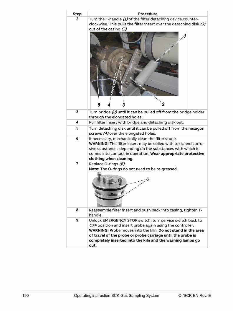
190 Operating instruction SCK Gas Sampling System OI/SCK-EN Rev. E
Step Procedure 2 Turn the T-handle (1) of the filter detaching device counter-
clockwise. This pulls the filter insert over the detaching disk (3) out of the casing (5).
3 Turn bridge (2) until it can be pulled off from the bridge holder
through the elongated holes. 4 Pull filter insert with bridge and detaching disk out. 5 Turn detaching disk until it can be pulled off from the hexagon
screws (4) over the elongated holes. 6 If necessary, mechanically clean the filter stone.
WARNING! The filter insert may be soiled with toxic and corro-sive substances depending on the substances with which it comes into contact in operation. Wear appropriate protective clothing when cleaning.
7 Replace O-rings (6). Note: The O-rings do not need to be re-greased.
8 Reassemble filter insert and push back into casing, tighten T-
handle. 9 Unlock EMERGENCY STOP switch, turn service switch back to
OFF position and insert probe again using the controller. WARNING! Probe moves into the kiln. Do not stand in the area of travel of the probe or probe carriage until the probe is completely inserted into the kiln and the warning lamps go out.

OI/SCK-EN Rev. E Operating instruction SCK Gas Sampling System 191
Probe retractor: Checking filter/pressure control combination
twice yearly
Always take the following safety measures when performing this work:
Wear the general protective equipment.
Turn the service switch to ON and secure the service switch against un-authorized switching (with a padlock).
Do not enter the danger area around the retractor until it is at standstill and the warning lamps and buzzer are off and the flap valve is closed.
Do not perform the work until the gas sampling system has cooled down.
When the warning lamps light up or the earning buzzer buzzes, leave the danger area around the probe retractor immediately as the probe is about to move at any moment.
Press the EMERGENCY STOP switch immediately if anyone is still in the danger area around the retractor after the warning lamps light up or the warning buzzer buzzes.
Avoid contact with lubricating oil.
Wash any lubricating oil off the skin immediately with water and soap.
If any lubricating oil gets in the eyes despite protective glasses, rinse them thoroughly under running water, holding the eyelids open.
Observe instructions in the lubricating oil manufacturer's safety data sheet.
Explanation of safety measures: Safety regulations for maintenance work on page 158.
The following conditions must be met:
The service switch is in the ON position; the gas sampling probe is retract-ed from the kiln (see Operating the service switch on page 161).
Maintenance interval
Safety measures
Requirements

192 Operating instruction SCK Gas Sampling System OI/SCK-EN Rev. E
Perform the following steps to check the filter/pressure control combination -J53:
Step Procedure 1 Check holding pressure set on manometer (2) (6 bar
(6000 hPa)). In the event of deviations, use knob (1) above to adjust.
2 No droplets of liquid or dust deposits must be visible in the
inspection window (3). 3 If there are any impurities, shut off the compressed-air inlet at
the shut-off valve -J54 (4). 4 Unscrew the filter casing by turning it counter-clockwise, re-
move impurities and clean the inside of the filter casing with a cloth.
5 Screw filter casing back on.
Note: During this procedure, also check central compressed-air supply for soiling. The system must not be switched on again until all impurities have been completely removed.
6 Open the compressed-air inlet again at the shut-off valve -J54 (4).
7 Turn service switch back to OFF position and insert probe again using the controller. WARNING! Probe moves into the kiln. Do not stand in the area of travel of the probe or probe carriage until the probe is completely inserted into the kiln and the warning lamps go out.
Instructions

OI/SCK-EN Rev. E Operating instruction SCK Gas Sampling System 193
Probe retractor: Checking and replacing the filter muffler
twice yearly
Always take the following safety measures when performing this work:
Wear the general protective equipment.
Turn the service switch to ON and secure the service switch against un-authorized switching (with a padlock).
Do not enter the danger area around the retractor until it is at standstill and the warning lamps and buzzer are off and the flap valve is closed.
Do not perform the work until the gas sampling system has cooled down.
When the warning lamps light up or the earning buzzer buzzes, leave the danger area around the probe retractor immediately as the probe is about to move at any moment.
Press the EMERGENCY STOP switch immediately if anyone is still in the danger area around the retractor after the warning lamps light up or the warning buzzer buzzes.
Avoid contact with lubricating oil.
Wash any lubricating oil off the skin immediately with water and soap.
If any lubricating oil gets in the eyes despite protective glasses, rinse them thoroughly under running water, holding the eyelids open.
Observe instructions in the lubricating oil manufacturer's safety data sheet.
Explanation of safety measures: Safety regulations for maintenance work on page 158.
The following conditions must be met:
The service switch is in the ON position; the gas sampling probe is com-pletely retracted from the kiln (see Operating the service switch on page 161).
Maintenance interval
Safety measures
Requirements

194 Operating instruction SCK Gas Sampling System OI/SCK-EN Rev. E
Perform the following steps to check the filter muffler on the compressed-air motor (-J83):
Step Procedure 1 Pull the drip cup (1) off the filter muffler -J83.
2 Unscrew filter element.
3 Inspect and, if necessary, replace filter element. 4 Screw filter element back on. 5 Put the drip cup back on. 6 Unlock EMERGENCY STOP switch, turn service switch back to
OFF position and insert probe again using the controller. WARNING! Probe moves into the kiln. Do not stand in the area of travel of the probe or probe carriage until the probe is completely inserted into the kiln and the warning lamps go out.
Instructions

OI/SCK-EN Rev. E Operating instruction SCK Gas Sampling System 195
Probe retractor: Checking and topping up the oiler
A compressed-air oiler at the end of the probe retractor ensures adequate delivery of lubricant to the compressed-air motor. Check oil level and oil deliv-ery rate before start-up and at regular intervals during operations.
twice yearly
Always take the following safety measures when performing this work:
Wear the general protective equipment.
Turn the service switch to ON and secure the service switch against un-authorized switching (with a padlock).
Do not enter the danger area around the retractor until it is at standstill and the warning lamps and buzzer are off and the flap valve is closed.
Do not perform the work until the gas sampling system has cooled down.
When the warning lamps light up or the earning buzzer buzzes, leave the danger area around the probe retractor immediately as the probe is about to move at any moment.
Press the EMERGENCY STOP switch immediately if anyone is still in the danger area around the retractor after the warning lamps light up or the warning buzzer buzzes.
Avoid contact with lubricating oil.
Wash any lubricating oil off the skin immediately with water and soap.
If any lubricating oil gets in the eyes despite protective glasses, rinse them thoroughly under running water, holding the eyelids open.
Observe instructions in the lubricating oil manufacturer's safety data sheet.
Always keep the floor around the gas sampling system clean and dry.
Explanation of safety measures: Safety regulations for maintenance work on page 158.
Lubricating oil "D" DIN 51502, kinematic viscosity 30 mm2/s(cST) at 40 °C (ISO VG 32, DIN 51519)
Screwdriver, short (to adjust oil delivery rate)
The following conditions must be met:
The service switch is in the ON position, the gas sampling probe is retract-ed from the kiln (see Operating the service switch on page 161).
Meaning
Maintenance interval
Safety measures
Lubricating oil
Tools required
Requirements

196 Operating instruction SCK Gas Sampling System OI/SCK-EN Rev. E
How to check oil level on the compressed-air oiler -J74:
Step Procedure 1 Check oil level in the tank inspection windows on the com-
pressed-air oiler -J74. Guidelines: Minimum: Bottom edge of the bottom inspection window Maximum: Top quarter in the top inspection window
2 Shut off the compressed-air using the gate valve -J54 (1) in the
pneumatic box of the probe retractor.
3 Completely drain the compressed-air tank (if present). 4 Unscrew the tank on the compressed-air oiler -J74 by turning it
counter-clockwise. 5 Fill oil up to the top quarter of the top inspection window and
screw tank back on. 6 Remove any oil residue with a cloth. 7 Open the compressed-air gate valve -J54 (1) again. 8 Turn service switch back to OFF position and insert probe
again using the controller. WARNING! Probe moves into the kiln. Do not stand in the area of travel of the probe or probe carriage until the probe is completely inserted into the kiln and the warning lamps go out.
Instructions: checking oil level

OI/SCK-EN Rev. E Operating instruction SCK Gas Sampling System 197
How to check oil delivery rate on the compressed-air oiler -J74 (note: two people should perform this job):
Step Procedure 1 Turn the setting screw in the inspection glass to modify the
quantity of oil. Meaning of the directions of rotation: counter-clockwise: more oil clockwise: less oil
Note: The compressed-air oiler -J74 must deliver approx. 2 drops of oil per insertion/retraction cycle. If this is not ensured, the compressed-air motor may get damaged or this may lead to excessive soiling of the muffler.
2 Move probe in/out to check oil quantity, modify again if neces-sary.
Instructions: checking oil delivery rate

198 Operating instruction SCK Gas Sampling System OI/SCK-EN Rev. E
Probe retractor: Checking and tightening the drive chain
Maintain adequate drive chain tension so as to prevent damage to the retrac-tor.
weekly or as required
Always take the following safety measures when performing this work:
Wear the general protective equipment.
Turn the service switch to ON and secure the service switch against un-authorized switching (with a padlock).
Additionally press the EMERGENCY STOP switch.
Do not enter the danger area around the retractor until it is at standstill and the warning lamps and buzzer are off and the flap valve is closed.
Do not perform the work until the gas sampling system has cooled down.
Explanation of safety measures: Safety regulations for maintenance work on page 158.
The following conditions must be met:
The service switch is in the ON position; the gas sampling probe is retract-ed from the kiln (see Operating the service switch on page 161).
The EMERGENCY STOP switch is pressed.
Meaning
Maintenance interval
Safety measures
Requirements

OI/SCK-EN Rev. E Operating instruction SCK Gas Sampling System 199
How to check drive tension:
Step Procedure 1 Check drive chain tension.
Target requirement: The upper chain is adequately tensioned when you can pull it down approx. 4-5 cm by hand.
2 If the chain droops or if you can pull it down further: Tension the drive chain with the chain tensioner in the probe carriage using the adjustment nuts (1) such that the upper part of the chain does not droop onto the lower part of the chain. Note: Ensure that the drive chain is not twisted. Also, ensure adequate tightening of the adjustment nuts.
3 Unlock EMERGENCY STOP switch, turn service switch back to
OFF position and insert probe again using the controller. WARNING! Probe moves into the kiln. Do not stand in the area of travel of the probe or probe carriage until the probe is completely inserted into the kiln and the warning lamps go out.
Instructions

200 Operating instruction SCK Gas Sampling System OI/SCK-EN Rev. E
Probe retractor: Checking and, if necessary, adjusting the position of the probe
Due to changes entailed by the process or the system it may be necessary to change the position of the gas sampling probe. Note that the tip of the probe should be max. 30 cm in the rotary kiln after start-up. The gas sampling probe must not be inserted further than absolutely necessary into the rotary kiln in order to minimize impacts on the unprotected area of the probe caused by the process.
every six months or as required (kiln conversion work, process changes)
Always take the following safety measures when performing this work:
Wear the general protective equipment.
Before commencing adjustment work, turn the service switch to ON and secure the service switch against unauthorized switching (with a pad-lock).
Additionally press the EMERGENCY STOP switch.
Do not enter the danger area around the retractor until it is at standstill and the warning lamps and buzzer are off and the flap valve is closed.
Do not perform the adjustment work until the gas sampling system has cooled down.
Explanation of safety measures: Safety regulations for maintenance work on page 158.
How to check probe position:
Step Procedure 1 With the probe inserted, check the distance between the flange
and the pipe sealing device. Target requirement: The flange must be touching.
2 If this target requirement is not met, adjust the probe by means of the following actions: Adjust the tube sealing device change vertical position change horizontal position.
Proceed as follows to realign the tube sealing device:
Step Procedure 1 Turn service switch to ON position.
WARNING! Gas sampling probe moves out of the kiln. Do not stand in the area of travel of the gas sampling probe or probe carriage until the probe is completely retracted and the warn-ing lamps go out.
Probe position
Maintenance interval
Safety measures
Instructions: checking probe position
Instructions: adjusting the tube sealing device

OI/SCK-EN Rev. E Operating instruction SCK Gas Sampling System 201
Step Procedure 2 Press EMERGENCY STOP switch and allow gas sampling probe
to cool down. WARNING! Risk of burning in the event of contact with the hot probe. Do not touch the probe until it has cooled down to below 50 °C.
3 Unscrew clamp screws (1) on the pipe sealing device until it is easy to move. If necessary, clean the outside of the probe pipe first.
4 Move pipe sealing device by the required amount. 5 Tighten clamp screws. Make sure that one of the springs is in
six 'o' clock position. 6 Turn service switch back to OFF position and insert probe
again using the controller. WARNING! Probe moves into the kiln. Do not stand in the area of travel of the probe or probe carriage until the probe is completely inserted into the kiln and the warning lamps go out.
Proceed as follows to change the vertical alignment of the gas sampling probe:
Step Procedure 1 Turn service switch to ON position.
WARNING! Gas sampling probe moves out of the kiln. Do not stand in the area of travel of the gas sampling probe or probe carriage until the probe is completely retracted and the warn-ing lamps go out.
2 Press EMERGENCY STOP switch and allow gas sampling probe to cool down. WARNING! Risk of burning in the event of contact with the hot probe. Do not touch the probe until it has cooled down to below 50 °C.
3 Unscrew counter nuts (1) on probe carriage.
Instructions: change vertical position

202 Operating instruction SCK Gas Sampling System OI/SCK-EN Rev. E
Step Procedure 4 Adjust adjustment screws (2) until the desired position is
achieved. Ensure even changes on both sides of the probe carriage. Note: To make work easier, have another person lift up the probe tip slightly.
5 Perform steps 1 to 2 on the other side of the probe carriage so
as to ensure equal distance to the rails. 6 Tighten counter nuts (1). 7 Unlock EMERGENCY STOP switch, turn service switch back to
OFF position and insert probe again using the controller. Check the position of the entire sampling pipe in relation to the mounting flange, adjust if necessary. WARNING! Probe moves into the kiln. Do not stand in the area of travel of the probe or probe carriage until the probe is completely inserted into the kiln and the warning lamps go out.
If you have changed the position of the probe as described, you must then check and, if necessary, adjust the end position sensor. Follow the instruc-tions in Probe retractor: Checking and, if necessary, adjusting the position indicator (probe end position) on page 204.
Proceed as follows to change the horizontal alignment of the gas sampling probe:
Step Procedure 1 Turn service switch to ON position.
WARNING! Gas sampling probe moves out of the kiln. Do not stand in the area of travel of the gas sampling probe or probe carriage until the probe is completely retracted and the warn-ing lamps go out.
2 Press EMERGENCY STOP switch and allow gas sampling probe to cool down. WARNING! Risk of burning in the event of contact with the hot probe. Do not touch the probe until it has cooled down to below 50 °C.
After changing vertical position
Instructions: changing horizontal position

OI/SCK-EN Rev. E Operating instruction SCK Gas Sampling System 203
Step Procedure 3 Unscrew adjustment screws (1), turn probe until the desired
position is achieved. Note: To make work easier, have another person lift up the probe tip slightly.
4 Tighten adjustment screws. 5 Unlock EMERGENCY STOP switch, turn service switch back to
OFF position and insert probe again using the controller. Check the position of the entire sampling pipe in relation to the mounting flange, adjust if necessary. WARNING! Probe moves into the kiln. Do not stand in the area of travel of the probe or probe carriage until the probe is completely inserted into the kiln and the warning lamps go out.
If you have changed the position of the probe as described, you must then check and, if necessary, adjust the end position sensor. Follow the instruc-tions in Probe retractor: Checking and, if necessary, adjusting the position indicator (probe end position) on page 204.
After changing horizontal position

204 Operating instruction SCK Gas Sampling System OI/SCK-EN Rev. E
Probe retractor: Checking and, if necessary, adjusting the position indicator (probe end position)
During operation, the probe position indicators may need to be readjusted. This can be causes, for example, by loose fastening elements.
every six months (or as required)
There are two inductive position indicators and one mechanical position indicator in the probe retractor. The two inductive (1, 2) indicators are mounted on the probe carriage and travel together with the probe, the me-chanical position indicator (3) is permanently mounted on the retractor.
The above-mentioned position indicators signal to the controller that the gas sampling probe has reached the respective position. The position indicators given in the above illustration signal the following positions:
No. Limit switch Signal/position 1 Inductive position indi-
cator -B71 The probe is completely inserted into the kiln.
2 Inductive position indi-cator -B72
The probe is completely retracted.
3 Mechanical position indicator -S72
The probe is retracted so far that it has reached the mechanical limit of the pneumatic motor.
Always take the following safety measures when performing this work:
Wear the general protective equipment.
Before commencing any work on the gas sampling system, turn the ser-vice switch to ON and secure the service switch against unauthorized switching (with a padlock).
Additionally press the EMERGENCY STOP switch before working on the retractor or probe.
Do not enter the danger area around the retractor until it is at standstill and the warning lamps and buzzer are off and the flap valve is closed.
Do not perform the work until the gas sampling system has cooled down.
Meaning
Maintenance interval
Illustration
Function of the position indicators
Safety measures
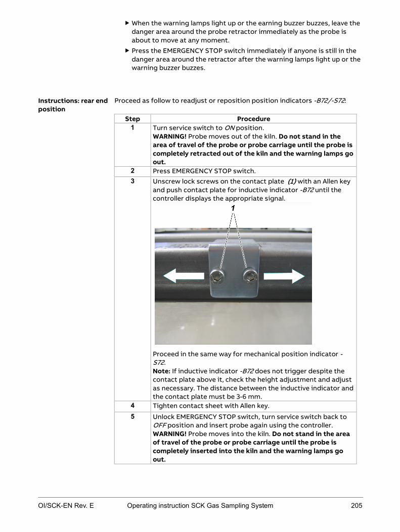
OI/SCK-EN Rev. E Operating instruction SCK Gas Sampling System 205
When the warning lamps light up or the earning buzzer buzzes, leave the danger area around the probe retractor immediately as the probe is about to move at any moment.
Press the EMERGENCY STOP switch immediately if anyone is still in the danger area around the retractor after the warning lamps light up or the warning buzzer buzzes.
Proceed as follow to readjust or reposition position indicators -B72/-S72:
Step Procedure 1 Turn service switch to ON position.
WARNING! Probe moves out of the kiln. Do not stand in the area of travel of the probe or probe carriage until the probe is completely retracted out of the kiln and the warning lamps go out.
2 Press EMERGENCY STOP switch. 3 Unscrew lock screws on the contact plate (1) with an Allen key
and push contact plate for inductive indicator -B72 until the controller displays the appropriate signal.
Proceed in the same way for mechanical position indicator -S72. Note: If inductive indicator -B72 does not trigger despite the contact plate above it, check the height adjustment and adjust as necessary. The distance between the inductive indicator and the contact plate must be 3-6 mm.
4 Tighten contact sheet with Allen key.
5 Unlock EMERGENCY STOP switch, turn service switch back to OFF position and insert probe again using the controller. WARNING! Probe moves into the kiln. Do not stand in the area of travel of the probe or probe carriage until the probe is completely inserted into the kiln and the warning lamps go out.
Instructions: rear end position

206 Operating instruction SCK Gas Sampling System OI/SCK-EN Rev. E
Proceed as follow to readjust or reposition position indicator -B71:
Step Procedure 1 Press the Insert button to move the probe to the desired posi-
tion. Path: Operation ► Probe ► Probe Action ► Insert
2 Determine necessary position of the contact plate, mark with an pen.
3 Turn service switch to ON position. WARNING! Probe moves out of the kiln. Do not stand in the area of travel of the probe or probe carriage until the probe is com-pletely retracted out of the kiln and the warning lamps go out.
4 Press EMERGENCY STOP switch. 5 Unscrew lock screws on the contact plate (1) with an Allen key
and push contact plate for inductive indicator -B71 until it reach-es the marked position.
6 Unlock EMERGENCY STOP switch. 7 Turn service switch to OFF position, then turn back to ON. 8 Press the Insert button to move the probe to the desired position
until the controller displays the appropriate signal (e.g.: Probe Inserted display box in the Probe Action dialog changes from white to black). Note: If inductive indicator -B71 does not trigger despite the contact plate above it, check the height adjustment and adjust as necessary. The distance between the inductive indicator and the contact plate must be 3-6 mm.
9 Tighten contact sheet with Allen key.
10 Unlock EMERGENCY STOP switch, turn service switch back to OFF position and insert probe again using the controller. WARNING! Probe moves into the kiln. Do not stand in the area of travel of the probe or probe carriage until the probe is com-pletely inserted into the kiln and the warning lamps go out.
Instructions: probe inserted position

OI/SCK-EN Rev. E Operating instruction SCK Gas Sampling System 207
Probe retractor: Checking the bellows
every two years
Always take the following safety measures when performing this work:
Wear the general protective equipment.
Turn the service switch to ON and secure the service switch against un-authorized switching (with a padlock).
Do not enter the danger area around the retractor until it is at standstill and the warning lamps and buzzer are off and the flap valve is closed.
Do not touch the gas sampling system during and after operation.
Do not touch the gas sampling system until it has cooled down to 50 °C.
Do not approach the retracted probe until it has cooled down.
When the warning lamps light up or the earning buzzer buzzes, leave the danger area around the probe retractor immediately as the probe is about to move at any moment.
Press the EMERGENCY STOP switch immediately if anyone is still in the danger area around the retractor after the warning lamps light up or the warning buzzer buzzes.
Explanation of safety measures: Safety regulations for maintenance work on page 158.
The following conditions must be met:
The service switch is in the ON position; the gas sampling probe is retract-ed from the kiln (see Operating the service switch on page 161).
The EMERGENCY STOP switch is pressed.
Proceed as follows to check the bellows:
Step Procedure 1 Unscrew the hose clamps on the cover. 2 Remove cover. 3 Check condition of retractor bellows:
general damage cracks abrasion
4 If the condition necessitates replacement, consult the service manual.
5 Put cover back on. 6 Fit and tighten hose clamps. 7 Unlock EMERGENCY STOP switch, turn service switch back to
OFF position and insert gas sampling probe again using the controller. WARNING! Gas sampling probe moves into the kiln. Do not stand in the area of travel of the gas sampling probe or probe carriage until the probe is completely inserted into the kiln and the warning lamps go out.
Maintenance interval
Safety measures
Requirements
Instructions

208 Operating instruction SCK Gas Sampling System OI/SCK-EN Rev. E
Cooling module: Vent the cooling-water circuit
every six months (or as required)
Always take the following safety measures when performing this work:
Wear the general protective equipment.
Turn the service switch to ON and secure the service switch against un-authorized switching (with a padlock).
Only specialized electrical personnel may work on the electrical system.
Do not perform work on the cooling-water circuit until the cooling water has cooled down.
Avoid contact with the cooling water and the anti-freeze.
Wash any cooling water and anti-freeze off the skin immediately with water and soap.
If cooling water or anti-freeze gets in the eyes despite protective glass-es, rinse them thoroughly under running water, holding the eyelids open.
Observe instructions in the anti-freeze manufacturer's safety data sheet.
Always keep the floor around the gas sampling system clean and dry.
Explanation of safety measures: Safety regulations for maintenance work on page 158.
Control cabinet key to open the control cabinet
The service switch is in the ON position, the gas sampling probe is retracted from the kiln (see Operating the service switch on page 161).
Proceed as follows to vent the cooling-water circuit:
Step Procedure 1 Open the control cabinet. 2 After retracting the probe wait until cooling-water temperature
has dropped to 40 °C; you can monitor this on the controller: Path: Diagnosis ► Trends ► Cooling Water Return Tempera-ture
Maintenance interval
Safety measures
Tools required
Requirements
Instructions

OI/SCK-EN Rev. E Operating instruction SCK Gas Sampling System 209
Step Procedure 3 Switch off the cooling-water pump -M51 at the motor breaker -
F37 (1).
Note: You can also switch off the cooling-water pump at circuit breaker -F36 (2).
4 Wait about 5 minutes. 5 On the top of the heat exchanger: Unscrew cap and slowly open
vent cock (red) so that air can escape.
6 Close drain valve on heat exchanger again as soon as only cool-
ing water comes out. 7 Switch cooling-water pump -M51 on again at motor breaker -
F37 (1) or at circuit breaker -F36 (2) for approx. 20 s. 8 Wait 5 minutes and vent again. 9 Repeat steps 7 and 8 until no more air comes out of the cool-
ing-water circuit. 10 Check pressure of cooling water in the controller and top up if
necessary (target cooling water pressure in cooled state: 1-1.5 bar (1000-1500 hPa)).
11 Switch cooling-water pump -M51 on again at motor breaker -F37 (1) or at circuit breaker -F36 (2) for approx. 20 s.
12 Close control cabinet again. 13 Turn service switch back to OFF position and insert probe
again using the controller. WARNING! Probe moves into the kiln. Do not stand in the area of travel of the probe or probe carriage until the probe is completely inserted into the kiln and the warning lamps go out.

210 Operating instruction SCK Gas Sampling System OI/SCK-EN Rev. E
Cooling module: Checking and topping up cooling water
The closed cooling-water circuit must be filled with approx. 50 l potable water (do not use anti-corrosive). In ambient temperatures below 0 °C admix ap-prox. 20 l anti-freeze.
If ambient temperatures below 0 °C can be expected, you must admix anti-freeze. ABB recommends Glykol as anti-freeze. Anti-freeze with anti-corrosive additive is not permitted.
Check cooling water pressure and cooling water flow rate on a daily basis. Completely replace the cooling water every two years.
Always take the following safety measures when performing this work:
Wear the general protective equipment.
Before commencing work on the cooling-water circuit, turn the service switch to ON and secure the service switch against unauthorized switch-ing (with a padlock).
Only specialized electrical personnel may work on the electrical system.
Do not perform work on the cooling-water circuit until the cooling water has cooled down.
Avoid contact with the cooling water and the anti-freeze.
Wash any cooling water and anti-freeze off the skin immediately with water and soap.
If cooling water or anti-freeze gets in the eyes despite protective glass-es, rinse them thoroughly under running water, holding the eyelids open.
Observe instructions in the anti-freeze manufacturer's safety data sheet.
Always keep the floor around the gas sampling system clean and dry.
Explanation of safety measures: Safety regulations for maintenance work on page 158.
Control cabinet key to open the control cabinet
The following steps are necessary to check cooling water pressure and cool-ing water flow rate:
Step Procedure
1 During operation, observe cooling water pressure and cooling water flow rate on the controller, Trends submenu.
2 Top up cooling water if pressure drops below 2-2.5 bar (2000-2500 hPa)in operation or cooling water flow rate is < 50 l/min.
Cooling-water requirements
Anti-freeze requirements
Maintenance interval
Safety measures
Tools required
Checking cooling water

OI/SCK-EN Rev. E Operating instruction SCK Gas Sampling System 211
Proceed as follows to top up cooling water:
Step Procedure 1 Turn service switch to ON position.
WARNING! Actuating the service switch moves the probe out of the kiln. Do not stand in the area of travel of the probe or probe carriage until the probe has reached its end position and the warning lamps go out.
2 Wait until cooling-water temperature has dropped to 40 °C; you can monitor this on the controller: Path: Diagnosis ► Trends ► Cooling Water Return Temp.
3 Open the control cabinet.
4 Switch off the cooling-water pump -M51 at the motor breaker -F37 (1).
Note: You can also switch off the cooling-water pump at circuit breaker -F36 (2).
5 Connect filling pipe to the cooling-water supply of the cooling module. If possible, the filling pipe should be filled with water before connecting it to the cooling module in order to prevent any additional air from entering the cooling-water circuit. Also, make sure (e.g. by rinsing beforehand) that no dirt is deposited in the filling pipe.
6 Unscrew cap and slowly open vent cock (red) so that air can escape.
7 Open shut-off valve -J63 and allow cooling water to flow in
slowly until bubble-free cooling water appears at the heat exchanger drain valve.
8 Close shut-off valve -J63.
Topping up cooling water

212 Operating instruction SCK Gas Sampling System OI/SCK-EN Rev. E
Step Procedure 9 Close vent cock on heat exchanger, screw on cap.
10 Open shut-off valve -J63 again slowly and observe cooling-water pressure display on the touchscreen. Fill cooling water to a pressure of 1-1.5 bar (1000-1500 hPa). Note: It is advisable for two people to do this job.
11 Switch the cooling-water pump -M51 on again at motor breaker -F37 or circuit breaker -F36.
12 Close control cabinet again. 13 Turn service switch back to OFF position and insert probe
again using the controller. WARNING! Probe moves into the kiln. Do not stand in the area of travel of the probe or probe carriage until the probe is completely inserted into the kiln and the warning lamps go out.
OI/SCK-EN Rev. E Operating instruction SCK Gas Sampling System 213
Pneumatic system: Replacing the compressed-air filter
yearly
Always take the following safety measures when performing this work:
Wear the general protective equipment.
Turn the service switch to ON and secure the service switch against un-authorized switching (with a padlock).
Do not enter the danger area around the retractor until it is at standstill and the warning lamps and buzzer are off and the flap valve is closed.
Do not perform the work until the gas sampling system has cooled down.
When the warning lamps light up or the earning buzzer buzzes, leave the danger area around the probe retractor immediately as the probe is about to move at any moment.
Press the EMERGENCY STOP switch immediately if anyone is still in the danger area around the retractor after the warning lamps light up or the warning buzzer buzzes.
Avoid contact with lubricating oil.
Wash any lubricating oil off the skin immediately with water and soap.
If any lubricating oil gets in the eyes despite protective glasses, rinse them thoroughly under running water, holding the eyelids open.
Observe instructions in the lubricating oil manufacturer's safety data sheet.
Always keep the floor around the gas sampling system clean and dry.
Explanation of safety measures: Safety regulations for maintenance work on page 158.
The service switch is in the ON position; the gas sampling probe is retracted from the kiln (see Operating the service switch on page 161).
Maintenance interval
Safety measures
Requirements

214 Operating instruction SCK Gas Sampling System OI/SCK-EN Rev. E
How to replace the compressed-air filter in the pneumatic box:
Step Procedure
1 Shut off compressed-air supply at gate valve -J54 (1) and wait until the manometer drops to 0 bar (0 hPa).
2 Unscrew filter element (2) (in Figure: filter element on fil-
ter/pressure control combination -J53).
3 Screw in new filter element hand-tight.
4 Perform steps 2 and 3 in the same way for pneumatic valves -J77, -J78 and -J79.
5 Open the compressed-air gate valve -J54 (1) again.
6 Turn service switch back to OFF position and insert probe again using the controller.
WARNING! Probe moves into the kiln. Do not stand in the area of travel of the probe or probe carriage until the probe is completely inserted into the kiln and the warning lamps go out.
Instructions

OI/SCK-EN Rev. E Operating instruction SCK Gas Sampling System 215
Chapter 10 Errors
Topic Page Errors and irregularities .................................................................................... 216
Touchscreen error displays .............................................................................. 218
Handling error messages ................................................................................. 223

216 Operating instruction SCK Gas Sampling System OI/SCK-EN Rev. E
Errors and irregularities
If an error occurs, the system triggers automatic processes to protect the gas sampling probe:
Phase Description
1 The sampling system is switched to manual mode.
2 The gas sampling probe is retracted out of the kiln.
WARNING! Probe movement. Do not stand in the area of travel of the probe or probe carriage.
Result: Because the gas sampling probe is in manual mode, the gas sampling probe can no longer move in on its own.
Note: In the event of danger to personnel, you can interrupt these automatic processes by pressing the EMERGENCY-STOP switch.
The following table describes irregularities that may occur during operation of the gas sampling system and measures to be taken to remedy them:
Observation Possible causes Measures Untypical running noise
Heat exchanger defective
Compressed-air motor defective
Inform internal mainte-nance department or ABB Service
Whistling noise from compressed-air system
Compressed-air system leak
See Checking for leaks on page 173
Probe travel is jerky
Probe carriage rails dirty
Wrong inclination of probe carriage
Clean rails Readjust probe carriage
inclination using the ad-justment screws, see Probe retractor: Check-ing and, if necessary, ad-justing the position of the probe on page 200
Probe not cen-tered in kiln aper-ture
Incorrect probe align-ment/positioning
Realign probe
Untypical or gur-gling noises in the cooling-water circuit
Air bubbles in the cooling-water circuit
Vent cooling-water cir-cuit, see Cooling module: Venting the cooling-water circuit on page 208
Top up cooling water, see Cooling module: Checking and topping up cooling water on page 210
Automatic processes
Irregularities and corrective action

OI/SCK-EN Rev. E Operating instruction SCK Gas Sampling System 217
Observation Possible causes Measures Unusual probe movements (probe rocks up and down, sways to the sides, jerky travel)
Loose parts Severe soiling of rails
Have trained experts find out the cause
Compressed-air hose bursts or compressed-air pipe cracks
Pressure controller defective
Incorrect pressure set on pressure con-troller
Close gate valve in pneumatic box, then wait for all compressed-air to blow out com-pletely before approach-ing
Shut down gas sampling system and secure against start-up until the cause has been fixed
Cooling-water pipe bursts or cracks
Mechanical damage to the pipe from out-side
Wait until all cooling water has run out before approaching
Shut down gas sampling system and secure against start-up until the cause has been fixed
Do not begin repair work until it has cooled down
Probe or heat exchanger cracks
Mechanical damage and thermal stress
Wait until all cooling water has run out before approaching
Shut down gas sampling system and secure against start-up until the cause has been fixed
Do not begin repair work until it has cooled down
Probe movement blocked
Mechanical damage Incrustation
Press EMERGENCY STOP switch before working on the probe
Remove blockage

218 Operating instruction SCK Gas Sampling System OI/SCK-EN Rev. E
Touchscreen error displays
The touchscreen on the front of the control cabinet displays error messages. All error messages do not appear directly on the touchscreen's Start screen but are rather stored in the logbook (Message screen). Touch the Message button on the interface to display this logbook.
You can display additional information in order to identify errors in detail as follows:
Step Procedure
1 Press the Message button on the touchscreen.
2 Select message using the scroll buttons.
3 Press Help button.
4 The touchscreen displays additional details.
Note: Use the scroll buttons to view longer texts.
The following table describes errors that may occur on the gas sampling system and measures to be taken to remedy them:
Error
display Plain text (not
stored in controller) Cause Measures
Stör Error One or several pending error messages
Rectify single error message
Faulty Entry: ___
Value input error The value input is great-er/less than the limits de-fined by the system
Observe tolerance ranges when entering values, see Default operating parameter settings on page 48
Emergency Stop Active
EMERGENCY STOP activated
The EMERGENCY-STOP switch was pressed
Find reason for activating the EMERGENCY STOP
Remove danger Unlock EMERGENCY-STOP
switch Press service switch WARNING! Actuating the
service switch moves the probe out of the kiln. Do not stand in the area of travel of the probe or probe carriage.
Protection Area OPEN
Protection area is not closed
Personnel protection area is not closed
Close the protection area Check switching contact If the contact is not used,
check the jumper Com-pressed Air Not OK
Central compressed-air supply input pres-sure too low
Central compressed-air supply disrupted
Pressure switch 577 error
Check central compressed-air supply
Check functioning and set-ting of pressure switch 577
Error display
Additional information
Measures

OI/SCK-EN Rev. E Operating instruction SCK Gas Sampling System 219
Error display
Plain text (not stored in controller)
Cause Measures
Error Com-pressed Air Emergency Tank
Minimum com-pressed-air emer-gency tank pressure not adequate
If the central compressed-air supply is also faulty, first remedy the cause for failure of the central com-pressed-air supply
Leak in tank supply pipes or tank itself
Pressure switch 578 error
Check central compressed-air supply
Check supply pipe to com-pressed-air emergency tank for leaks
Check functioning and set-ting of pressure switch 578
Sample Gas Probe Pres-sure MIN
Sample gas main alarm low pressure not reached
Gas sampling probe clogged
Sample gas line clogged
Check and, if necessary, clean gas sampling probe
Check and, if necessary, clean sample gas line
Probe Heat-ing Temp. MIN
Probe heating tem-perature too low
At start-up probe heating not switched on long enough
Probe heating defective Defect in temperature
controller Heating connection cable
damaged Heating sleeve defective
Wait for heating-up time (approx. 20 min)
Check probe heating for proper functioning
Probe Heat-ing Temp. MAX
Probe heating tem-perature too high
Probe heating overheating Check PT100 sensor
Probe Heat-ing Temp. MIN
Probe heating tem-perature too low
At start-up probe heating not switched on long enough
Probe heating defective Defect in temperature
controller Heating connection cable
damaged Heating sleeve defective
Wait for heating-up time (approx. 20 min)
Check probe heating for proper functioning
Cable Drag Chain Sam-ple Gas Line Temp. Error
Cable drag chain sample gas line temp. error
Cable drag chain heating not switched on long enough
Cable drag chain heating defective
Wait for heating-up time (approx. 20 min)
Check heating for proper functioning
Error Posi-tion Switch Probe Ac-tion
Probe movement limit switch error
Front and at least one of the two rear limit switches for probe movement trig-gered simultaneously
Check function and position of limit switches
Check position of trigger element
Error 3x Cleaning Not Suc-cessful Probe H
Probe cleaning failed after 3x cleaning
Cleaning cycle can no longer clean probe H ade-quately
Remove dirt sticking to the gas inlet
Clean the filter element Check compressed-air sup-
ply and solenoid valves of probe cleaning system
Error Posi-tion Switch Plunger Action
Plunger movement limit switch error
Both plunger movement limit switches triggered simultaneously
Check function and position of limit switches

220 Operating instruction SCK Gas Sampling System OI/SCK-EN Rev. E
Error display
Plain text (not stored in controller)
Cause Measures
Error Plunger Out
Plunger failed to reach front end posi-tion after set control time
Plunger blocked In connection with com-
pressed air error: insuffi-cient compressed-air sup-ply
Check central compressed-air supply
Check plunger for mechani-cal blocking and rectify as needed
Check compressed-air sup-ply to pneumatic cylinder of probe H
Error Plunger In
Plunger failed to reach rear end posi-tion after set control time
Plunger blocked In connection with com-
pressed air error: insuffi-cient compressed-air sup-ply
Check central compressed-air supply
Check plunger for mechani-cal blocking and rectify as needed
Check compressed-air sup-ply to pneumatic cylinder of probe H
Error Probe H Blocked During Retraction
Probe movement blocked during re-traction
Incrustation on probe tip Duct opening clogged up Retractor drive defect Front limit switch error
Check gas sampling probe for incrustation
Check and, if necessary, clean gas sampling probe entry zone
Check gas sampling probe travel time, modify speed setting if necessary
Error Probe H Blocked During Insertion
Probe movement blocked during inser-tion
Incrustation on probe tip Duct opening clogged up Retractor drive defect Shutter drive defect Front limit switch error
Check shutter functioning Check drive and limit switch
of shutter Check gas sampling probe
for incrustation Check and, if necessary,
clean gas sampling probe entry zone
Check gas sampling probe travel time, modify speed setting if necessary
Error 3x Cleaning Not Suc-cessful Probe 60
Probe cleaning failed after 3x
Cleaning cycle can no longer clean probe 60S ad-equately
Remove dirt sticking to the gas inlet
Clean the filter element Check compressed-air sup-
ply and solenoid valves of probe cleaning system
Error Probe 60 Blocked During Retraction
Probe movement blocked during re-traction
Incrustation on probe tip Duct opening clogged up Retractor drive defect Rear limit switch error
Check gas sampling probe for incrustation
Check rear limit switch for proper functioning
Check and, if necessary, clean gas sampling probe entry zone
Check gas sampling probe travel time, modify speed setting if necessary

OI/SCK-EN Rev. E Operating instruction SCK Gas Sampling System 221
Error display
Plain text (not stored in controller)
Cause Measures
Error Probe 60 Blocked During Insertion
Probe movement blocked during inser-tion
Incrustation on probe tip Duct opening clogged up Retractor drive defect Shutter drive defect Front limit switch error
Check gas sampling probe for incrustation
Check shutter functioning Check drive and limit switch
of shutter Check and, if necessary,
clean gas sampling probe entry zone
Check gas sampling probe travel time, modify speed setting if necessary
C. Water Flow Temp. MAX
Cooling-water flow temperature main alarm high exceeded
Insufficient heat exchang-er cooling output
Check heat exchanger for soiling and, if necessary, clean
C. Water Flow Temp. MIN
Cooling-water flow temperature too low
Cooling water not heated up enough
With probe inserted, wait for heating-up time to finish
C. Water Flow / Return Temp. Diff. MIN
Difference too small between cooling-water flow and re-turn
Minor heat build-up on probe tip due to severe in-crustation.
Check gas sampling probe for incrustation and, if nec-essary, clean
C. Water Flow Rate MIN
Cooling-water flow rate pre-alarm low not reached
Insufficient capacity of cooling-water pump
Cooling water tempera-ture too low
Bent cooling-water tube
Vent the cooling-water cir-cuit
Check cooling-water level and, if necessary, top up
If necessary, replace pump C. Water Flow Rate MIN2
Cooling-water flow rate main alarm low not reached
Insufficient capacity of cooling-water pump
Cooling water tempera-ture too low
Bent cooling-water tube
Vent the cooling-water cir-cuit
Check cooling-water level and, if necessary, top up
If necessary, replace pump C. Water Pressure MIN
Cooling-water pres-sure pre-alarm low not reached
Insufficient capacity of cooling-water pump
Cooling-water circuit leak
Check cooling-water circuit for leaks, fix leaks, top up cooling water if necessary
Check delivery rate of cool-ing-water pump
C. Water Pressure MIN2
Cooling-water pres-sure main alarm low not reached
Cooling-water circuit leak Probe leak Cooling-water pump leak Insufficient capacity of
cooling-water pump
Check cooling-water circuit for leaks, fix leaks, top up cooling water if necessary
Check delivery rate of cool-ing-water pump
C. Water Pressure MAX
Cooling-water pres-sure main alarm high exceeded
Cooling-water circuit fill-ing pressure too high
Ensure correct filling pres-sure
Error C. Water Module
Centralized cooling module error mes-sage
Circuit breaker tripped Switch circuit breaker back on
If it trips again, locate and remedy cause
CAN Error Slave 1
Can bus error to slave 1
Can bus connection error to slave 1 -D31
Check CAN bus cable for damage
Contact ABB Service if nec-essary

222 Operating instruction SCK Gas Sampling System OI/SCK-EN Rev. E
Error display
Plain text (not stored in controller)
Cause Measures
CAN Error Slave 2
Can bus error to slave 2
Can bus connection error to slave 2 -D32
Check CAN bus cable for damage
Contact ABB Service if nec-essary
CAN Error Slave 3
Can bus error to slave 3
Can bus connection error to slave 3 -D33
Check CAN bus cable for damage
Contact ABB Service if nec-essary
CAN Error Slave 4
Can bus error to slave 4
Can bus connection error to slave 4 -D51
Check CAN bus cable for damage
Contact ABB Service if nec-essary
CAN Error Slave 5
Can bus error to slave 5
Can bus connection error to slave 5 -D71
Check CAN bus cable for damage
Contact ABB Service if nec-essary
CAN Error Slave 6
Can bus error to slave 6
Can bus connection error to slave 6 -D72
Check CAN bus cable for damage
Contact ABB Service if nec-essary
CAN Error Slave 7
Can bus error to slave 7
Can bus connection error to slave 7 -D73
Check CAN bus cable for damage
Contact ABB Service if nec-essary
CAN Error Slave 8
Can bus error to slave 8
Can bus connection error to slave 8 -K31
Check CAN bus cable for damage
Contact ABB Service if nec-essary
CAN Error Slave 9
Can bus error to slave 9
Can bus connection error to slave 9 -D74
Check CAN bus cable for damage
Contact ABB Service if nec-essary

OI/SCK-EN Rev. E Operating instruction SCK Gas Sampling System 223
Handling error messages
Always take the following safety measures when performing this work:
Wear the general protective equipment.
Before commencing any work on the gas sampling system, turn the ser-vice switch to ON and secure the service switch against unauthorized switching (with a padlock).
Additionally press the EMERGENCY-STOP switch before working on the retractor or probe.
Do not enter the danger area around the retractor until it is at standstill and the warning lamps and buzzer are off.
Never stand in the danger area around the retractor when the protective installation is closed.
When the warning lamps light up or the earning buzzer buzzes, leave the danger area around the probe retractor immediately as the probe is about to move at any moment.
Press the EMERGENCY-STOP switch immediately if anyone is still in the danger area around the retractor after the warning lamps light up or the warning buzzer buzzes.
Explanation of safety measures: Safety regulations for maintenance work on page 158.
In the event of an error, the probe is automatically retracted out of the kiln until the probe reaches its end position. To make sure that it really has reached its end position and that no unexpected probe movement can be expected, wait for the warning lamps on the retractor terminal box to go out before fixing the errors.
Proceed as follows to fix errors:
Step Procedure 1 Turn service switch to ON position.
When working on the retractor and gas sampling probe, addi-tionally actuate the EMERGENCY-STOP switch for reasons of safety.
2 Fix errors. DANGER! Fixing errors requires special training and involves working on the open and powered-on gas sampling system. Therefore this may only be carried out by qualified and specially trained personnel.
3 Turn service switch to OFF position. 4 In controller: insert the probe.
Path: Operation ► Probe ► Probe Action ► Insert WARNING! The probe moves into the kiln. Do not stand in the area of travel of the probe or probe carriage.
5 In controller: switch gas sampling system to Automatic mode. Path: Operation ► Automatic on / off
Safety measures
Requirements
Instructions

OI/SCK-EN Rev. E Operating instruction SCK Gas Sampling System 225
Chapter 11 Shutting down, storing, putting back into operation, disposal
Topic Page Shutting down the system ............................................................................... 226
Disassembling the system ............................................................................... 229
Storing the system............................................................................................. 232
Putting the system back into operation ........................................................ 233
Disposing of the system ................................................................................... 234

226 Operating instruction SCK Gas Sampling System OI/SCK-EN Rev. E
Shutting down the system
These instructions describe how to shut down the gas sampling probe. Note that the cooling water should only be drained if the system is shut down for prolonged periods or if it is subsequently disassembled. Otherwise the cool-ing water can stay in the system.
Risk of injury in the area of the gas sampling system due to moving or fall-ing parts, hot surfaces, hot cooling water, anti-freeze, compressed air, lubricating oil
Wear general personal protective equipment:
Closed overalls with long trousers and long sleeves Safety shoes Safety gloves suitable for mechanical work Safety glasses Protective helmet If necessary, additional protective equipment if prescribed by the opera-
tor.
danger of burning due to hot surfaces during and after operation of the gas sampling system. Do not touch the gas sampling system during and after operation. Do not touch the gas sampling system until it has cooled down to 50 °C.
Specifically, do not touch the cooling module, the heated sample gas line, the connection box for the heated sample gas line on the retractor, the heated sampling filter, the entire gas sampling probe, the metal structure of the retractor, the shutter of the duct opening. If it is unavoidable to touch hot components, wear a face mask against
heat, heat-proof gloves and protective welder's clothing.
Danger of injury to skin and eyes in the event of contact with cooling water or anti-freeze. Avoid contact with the cooling water and the anti-freeze.
Wash any cooling water and anti-freeze off the skin immediately with water and soap.
If cooling water or anti-freeze gets in the eyes despite protective glass-es, rinse them thoroughly under running water, holding the eyelids open.
Observe instructions in the anti-freeze manufacturer's safety data sheet.
Meaning
Mechanical, thermal and material dangers
Hot surfaces
Harmful anti-freeze

OI/SCK-EN Rev. E Operating instruction SCK Gas Sampling System 227
The following conditions must be met:
The system is switched off at the main switch. Central compressed-air supply shut off, gate valve in pneumatic box closed
(compressed-air pipes are vented). Rotary kiln is shut down. The system has cooled down.
Perform the following steps to shut down the system:
Step Procedure 1 Secure the closed shutter on the duct flange with the enclosed
locking device. 2 Unscrew sample gas line screw connection on the analyzer
cabinet and gas sampling probe. 3 Flush sample gas line, filter unit and sample gas probe with dry,
dust-free and oil-free instrument air (flow rate approx. 100 l/h) for about 15 minutes.
4 Clean any residue and incrustations off the filter unit and probe pipe. Note: Only clean mechanically. Do not use chemicals (particu-larly acids and lyes) for cleaning.
Requirements
Instructions: Shutting down
228 Operating instruction SCK Gas Sampling System OI/SCK-EN Rev. E
Proceed as follows to drain the cooling water:
Step Procedure 1 Unscrew cap and slowly open vent cock (1) so that air can es-
cape.
2 Open drain valves (2) on probe pipe.
3 Detach cooling-water tubes from screw connectors on the
cooling module and allow cooling water to drain. Empty any remaining water in the cooling-water tubes. If anti-freeze (Glykol) was admixed, observe disposal regulations in accord-ance with national legislation.
Refer to Disassembling the system on page 229 for details on further proce-dure.
Instructions: Draining cooling water
Further procedure

OI/SCK-EN Rev. E Operating instruction SCK Gas Sampling System 229
Disassembling the system
Risk of injury in the area of the gas sampling system due to moving or fall-ing parts, hot surfaces, hot cooling water, anti-freeze, compressed air, lubricating oil
Wear general personal protective equipment:
Closed overalls with long trousers and long sleeves Safety shoes Safety gloves suitable for mechanical work Safety glasses Protective helmet If necessary, additional protective equipment if prescribed by the opera-
tor.
Danger of crushing when lifting or lowering the transport unit Only appropriately trained personnel may transport the transport units and
only with the aid of the recommended transport equipment. Do not stand under suspended loads. Follow the transport instructions in these operating instructions care-
fully.
Risk of burning due to jet flames and hot gases at the uncovered duct open-ing when the rotary kiln is in operation Preferably install or remove the probe when the rotary kiln is out of opera-
tion. If you install or remove the probe when the rotary kiln is in operation: Wear a face mask against heat, heat-proof gloves and protective weld-
er's clothing and respiratory protection against toxic gases. Keep the time in which the duct opening is open as short as possible.
Danger due to harmful dusts when cleaning the gas sampling system Wear a dust mask when cleaning. Wash any dust off the skin immediately with water and soap.
Risk of falling on slippery floor due to escaped or spilled cooling water and lubricating oil or dirt Always keep the floor around the gas sampling system clean and dry.
Mechanical, thermal and material dangers
Heavy transport units
Hot surfaces, hot gases, jet flames
Harmful dusts
Slippery floor

230 Operating instruction SCK Gas Sampling System OI/SCK-EN Rev. E
The following conditions must be met to disassemble the system:
System must have been properly shut down (see Shutting down the sys-tem on page 226).
Cooling water must be drained (see Shutting down the system on page 226).
Probe retractor powered off and unpressurized (by trained personnel).
How to disassemble the gas sampling system:
Step Procedure 1 Clean the whole system roughly with compressed air and/or
brush. 2 Remove oil from compressed-air oiler and dispose of it in
accordance with national regulations. Note: Observe safety and disposal regulations for the particu-lar oil.
3 Label all connection lines to prevent confusion. 4 Detach connection lines. 5 Unscrew fastening screws on cooling module and control
cabinet and transport modules away. Perform the same steps for the transformer and compressed-air tank (if present).
6 Suspend probe retractor at its attachment points using suita-ble lifting gear. Note: Pay particular attention to suitable fastening points for the lifting equipment on the system. Observe relevant local regulations.
7 Unscrew and remove fastening screws on mounting flange and attachment points.
8 Using lifting gear, lower probe retractor until you can screw on the enclosed transport supports.
9 Place probe retractor on ground and secure from falling over.
Requirements
Instructions
OI/SCK-EN Rev. E Operating instruction SCK Gas Sampling System 231
The following table shows further procedure:
If the system ... follow the following instructions: is to be stored for a pro-longed period
Storing the system on page 232.
is to be disposed of Disposing of the system on page 234. is to be relocated Transporting the system in the company on
page 89. is to be unpacked and transported to another place
Do not transport the probe retractor without transport supports. Use adequately load-bearing and rigid pallets. Use suitably sized transport crates for longer-distance transports. Fasten sampling probe firmly on re-tractor if it is not being demounted. Note: The retractor must not be transported by fork-lift truck without suitable additional transport packaging.
is to be put back into operation
Start-up on page 111.
Further procedure

232 Operating instruction SCK Gas Sampling System OI/SCK-EN Rev. E
Storing the system
Store in a place protected from the weather. Observe the designated storage temperatures and humidities. The transport packing, if present, should not be removed during storage. In the event that the gas sampling system is tempo-rarily shut down, ensure suitable wrapping.
Observe the following instructions with regard to storing the various mod-ules:
Module Storage conditions Retractor including probe
During storage, support the tip of the assembled gas sampling probe.
Only store after draining all water. Cooling module Only store after draining all water. Control cabinet Store on rear side lying on pallet Transformer (optional)
Store on pallet Ensure storage in a dry area (no condensation!).
Compressed-air tank (optional)
Ensure adequate protection of the attachments. Only store after draining all water.
Observe the following physical limits with regard to storing the various mod-ules:
Module Environmental conditions for storage Retractor including probe
Ambient temperature: +5 °C to +55 °C; after completely draining all water and drying parts in contact with cool-ing water or condensation: -20 °C to +55 °C Air humidity: Year-round average max. 75 %, short-term max. 95 %, occasional slight condensation is permitted
Cooling module Ambient temperature: +5 °C to +55 °C; after completely draining all water and drying parts in contact with cool-ing water or condensation: -20 °C to +55 °C Air humidity: Year-round average max. 75 %, short-term max. 95 %, occasional slight condensation is permitted
Control cabinet Ambient temperature: -20 °C to +55 °C Air humidity: Year-round average max. 75 %, short-term max. 95 %, occasional slight condensation is permitted
Transformer (optional)
Ambient temperature: -25 °C to +55 °C Air humidity: Year-round average max. 80 %, short-term max. 95 %, without condensation
Compressed-air tank (optional)
Ambient temperature: +5 °C to +55 °C; after completely draining all water and drying parts in contact with cool-ing water or condensation: -20 °C to +55 °C Air humidity: Year-round average max. 75 %, short-term max. 95 %, occasional slight condensation is permitted
General storage information
Storing the various modules
Environmental conditions

OI/SCK-EN Rev. E Operating instruction SCK Gas Sampling System 233
Putting the system back into operation
Follow the instructions given in Start-up on page 111 to put the system back into operation.
Instructions
234 Operating instruction SCK Gas Sampling System OI/SCK-EN Rev. E
Disposing of the system
Danger of injury to skin and eyes in the event of contact with cooling water or anti-freeze Avoid contact with the cooling water and the anti-freeze.
Wash any cooling water and anti-freeze off the skin immediately with water and soap.
If cooling water or anti-freeze gets in the eyes despite protective glass-es, rinse them thoroughly under running water, holding the eyelids open.
Observe instructions in the anti-freeze manufacturer's safety data sheet.
Danger due to skin and eye injuries in the event of contact with lubricating oil from the pneumatic box of, from the filter muffler or from inside the pneumatic motor Avoid contact with lubricating oil.
Wash any lubricating oil off the skin immediately with water and soap.
If any lubricating oil gets in the eyes despite protective glasses, rinse them thoroughly under running water, holding the eyelids open.
Observe instructions in the lubricating oil manufacturer's safety data sheet.
The following conditions must be met:
System was properly shut down and disassembled (see Shutting down the system on page 226, Disassembling the system on page 229).
Drain oil from compressed-air oiler and dispose of it in accordance with national regulations. Note: Observe safety and disposal regulations for the particular oil.
Drain cooling water from the cooling module. Note: If anti-freeze (Glykol) was admixed, observe disposal regulations in ac-cordance with national legislation.
Remove filter elements out of the gas sampling probe. Note: Contamination with filter dust can be expected. The safety and disposal regulations apply that also apply to handling and disposal of other filter dusts at the cement works.
All other components of the gas sampling system must be disposed of expertly and in accordance with national legislation.
Harmful anti-freeze
Harmful lubricating oil
Requirements
Disposal rules

OI/SCK-EN Rev. E Operating instruction SCK Gas Sampling System 235
Chapter 12 Appendix
Topic Page Pneumatic/hydraulic interface plan ............................................................... 236
Electrical connection plan................................................................................. 238
Transformer connection plan ......................................................................... 240

236 Operating instruction SCK Gas Sampling System OI/SCK-EN Rev. E
Pneumatic/hydraulic interface plan
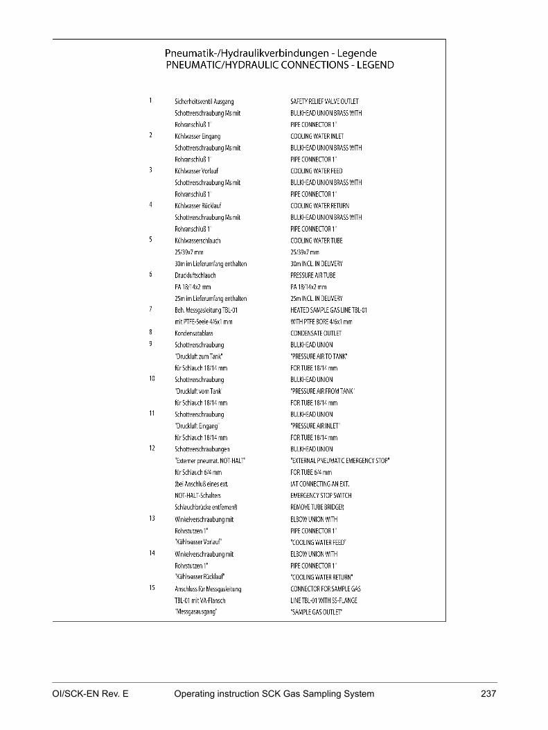
OI/SCK-EN Rev. E Operating instruction SCK Gas Sampling System 237

238 Operating instruction SCK Gas Sampling System OI/SCK-EN Rev. E
Electrical connection plan

OI/SCK-EN Rev. E Operating instruction SCK Gas Sampling System 239

240 Operating instruction SCK Gas Sampling System OI/SCK-EN Rev. E
Transformer connection plan

OI/SCK-EN Rev. E Operating instruction SCK Gas Sampling System 241
Index
A
About these operating instructions • 6 Access permissions • 47 Acquiring spare parts and wear parts • 157 Activation • 118 After switching on
working on the cooling module • 121 Anti-freeze • 114 Appendix • 235
B
Basic safety rules • 54
C
Checking for leaks • 173 Checking general condition • 141 Checking protective installations • 169 Checking site conditions • 95 Checking the condition of the system, cleaning the
system • 163 Checking the pneumatic system • 123 Checking the residual current circuit breaker • 167 Checking/correcting operating parameters • 126 Checks to perform when using probe H • 127 Cleaning gas sampling probe 60S • 145 Cleaning gas sampling probe H • 143 Cleaning procedures
Probe 60S • 28, 145 Probe H • 26, 143
Compressed-air tank and pneumatic system • 33 Connecting external electric cables • 108 Connecting internal electric cables • 106 Connecting the sample gas line to the retractor •
105 Controls and displays • 22 Cooling module • 30
Checking and topping up cooling water • 210 Vent the cooling-water circuit • 208
D
Default operating parameter settings • 48
Description of control system • 35 Description of the sampling system • 15 Dimensions and weights • 16 Disassembling the system • 229 Disposal • 234 Disposing of the system • 234
E
Electrical connection plan • 238 Emergency Stop • 147 Equipment layout plan • 154 Error message display • 46 Errors • 215 Errors and irregularities • 216 Evaluating trend displays • 166
G
Gas sampling probe 60S • 28 Cleaning or replacing the outlet filter • 186 Removing incrustations • 184 Replacing the seal set • 189
Gas sampling probe H • 26 Removing incrustations • 176 Replacing membrane pump membranes • 181 Replacing the intake filter • 178
General • 5 General transport information • 86
H
Handling error messages • 223
I
Inserting the probe and switching to automatic mode • 130
Installation • 93 Installation check • 113 Installing the compressed-air supply • 101 Installing the control cabinet • 100 Installing the cooling module • 103 Installing the cooling water circuit • 104 Installing the probe retractor • 97 Intended conditions of use • 17

242 Operating instruction SCK Gas Sampling System OI/SCK-EN Rev. E
L
Lubricating oil • 116
M
Maintenance • 149 Maintenance mode • 161 Maintenance plan • 150 Minimum compressed-air requirements • 33 Mode of functioning and operating modes • 19 Modes • 19 Monitoring automatic mode • 139
N
Nameplate • 10
O
Operating parameters Basic parameters • 48, 51 Limit parameters • 48, 51 Time parameters • 48, 51
Operating the service switch • 161 Operation • 135 Optimizing operating parameters • 51 Overview
installation • 94 Start-up • 112
Overview of dangers • 57
P
Personal safety equipment • 67 Pneumatic system
Replacing the compressed-air filter • 213 Pneumatic/hydraulic interface plan • 236 Preparing the compressed-air supply • 116 Preparing the cooling-water circuit • 114 Probe retractor • 24
Checking and replacing the filter muffler • 193 Checking and tightening the drive chain • 198 Checking and topping up the oiler • 195 Checking and, if necessary, adjusting the
position indicator (probe end position) • 204
Checking and, if necessary, adjusting the position of the probe • 200
Checking filter/pressure control combination • 191
Checking the bellows • 207 Process monitoring • 20 Protective installations • 59 Putting back into operation • 233 Putting the system back into operation • 233
R
Requirements to be met by personnel, work places • 65
S
Safety • 53 Safety instructions in this document • 8 Safety measures
Installation • 69 Maintenance and troubleshooting • 80 Operation • 76 Start-up • 72 Transport and unpacking • 68
Safety regulations for maintenance work • 158 Safety regulations for operation • 136 Scope of delivery • 92 Service • 13 Shutting down the system • 226 Shutting down, storing, putting back into
operation, disposal • 225 Starting frequency converter and adapting control
parameters • 124 Start-up • 111 Storing the system • 232 Structure and function • 18 Structure and function of the control system • 36 System identification • 10
T
Technical data • 16 Tolerance ranges, tolerances • 48 Touchpanel • 22, 35, 36, 47 Touchscreen error displays • 218 Transformer • 32 Transformer connection plan • 240 Transport and unpacking • 85

OI/SCK-EN Rev. E Operating instruction SCK Gas Sampling System 243
Transport supports • 24, 89 Transport the system in the company • 89
U
Unpacking the system • 91 User interface
Message screen • 42 Operation screen • 38 Parameter screen • 44 Trend screen • 40
Using the EMERGENCY-STOP switch • 147
W
Warning signs on the system • 63 Work places • 65

— A B B M EA S U R E M E NT & A NA LY TIC S | O PE RA TING INS TR U C TIO N | O I/ S C K - E N R E V . E
SCK Sample conditioning for kiln
— ABB Measurement & Analytics For your local ABB contact, visit: www.abb.com/contacts For more product information, visit: www.abb.com/analytical
Sampling system for dry gas sampling at rotary cement kiln gas exit and calciner gas exit
Measurement made easy
OI/
SCK
-EN
Rev
. E
07.
2021
O
rig
inal
inst
ruct
ion
— SCK Introduction
The SCK is a sampling system for dry gas sampling at rotary kiln exit and calciner gas exit. The SCK sampling system is suitable for applications in rough environmental conditions and for outdoor installations thanks to a complete protection cover.
Additional Information Additional documentation on SCK is available for download free of charge at www.abb.com/analytical. Alternatively simply scan this code:
— We reserve the right to make technical changes or modify the contents of this document without prior notice. With regard to purchase orders, the agreed particulars shall prevail. ABB does not accept any responsibility whatsoever for potential errors or possible lack of information in this document. We reserve all rights in this document and in the subject matter and illustrations contained therein. Any reproduction, disclosure to third parties or utilization of its contents – in whole or in parts – is forbidden without prior written consent of ABB. © ABB 2021 3KXG141003R4201