Scale-up of a continuous-jet hydrate reactor for CO2 ocean sequestration
11
ENVIRONMENTAL AND ENERGY ENGINEERING Scale-Up of a Continuous-Jet Hydrate Reactor for CO 2 Ocean Sequestration Costas Tsouris, Scott McCallum, Douglas Aaron and David Riestenberg Oak Ridge National Laboratory, Oak Ridge, TN 37831 Jorge Gabitto Chemical Engineering Dept., Prairie View A and M University, Prairie View, TX 77446 Aaron Chow and Eric Adams Dept. of Civil and Environmental Engineering, Massachusetts Institute of Technology, Cambridge, MA 02139 DOI 10.1002/aic.11117 Published online February 16, 2007 in Wiley InterScience (www.interscience.wiley.com). In previous work in our laboratories and in the ocean, we have investigated the forma- tion and dissociation of composite CO 2 particles made of CO 2 hydrate, liquid CO 2 , and water. The composite is formed by partially converting liquid CO 2 into hydrate at mid- ocean depth (1000–1200 m) conditions. Partial conversion of CO 2 into hydrate enables injection of CO 2 in seawater in the form of a dense composite material that will drive CO 2 to ocean depths well below the injection point. Thermodynamic conditions allowing the formation of negatively buoyant composite particles have been established for a labora- tory-scale, continuous-jet hydrate reactor (CJHR). An investigation has been performed to explore the issues related to the scale-up of the CJHR. Hydrate was formed using two CJHR geometries; the first sprayed water in CO 2 , and the second sprayed CO 2 in water. Using a plot of Ohnesorge vs. Reynolds numbers allowed flow rates to be selected that would yield a spray regime and maximize hydrate formation. The effect of varying pressure and liquid flow rates on hydrate behavior was observed. Depending on these parameters, hydrate particles were observed to sink, float, or be neutrally buoyant. A two-order-of- magnitude scale-up in the flow rates of the two fluids has been achieved with the larger CJHR geometries without losing the important characteristics of the hydrate particles (i.e., density and cohesiveness). Temperature changes as a result of hydrate formation were also monitored. A mathematical model has been developed to predict the fate of sink- ing CO 2 hydrate particles after release in the seawater. These results can guide further field and laboratory investigations related to the scale-up of ocean CO 2 sequestration. Ó 2007 American Institute of Chemical Engineers AIChE J, 53: 1017–1027, 2007 Keywords: CO 2 sequestration, CO 2 ocean injection, CO 2 hydrate, hydrate reactor Introduction Atmospheric CO 2 currently has a concentration of ;375 ppm and is considered an important factor in global warming. It has been proposed that CO 2 levels reach no greater than 500 ppm atmospheric concentration, almost double the preindus- trial concentration. 1 This goal has led to a considerable effort to efficiently separate and sequester anthropogenic CO 2 . Various technologies are being investigated for the separa- tion of CO 2 . In addition to the traditional technologies of absorption, adsorption, cryogenic distillation, and membrane diffusion, 2 novel methods are also being explored. Various Correspondence concerning this article should be addressed to C. Tsouris at [email protected]. Ó 2007 American Institute of Chemical Engineers AIChE Journal April 2007 Vol. 53, No. 4 1017
-
Upload
independent -
Category
Documents
-
view
3 -
download
0
Transcript of Scale-up of a continuous-jet hydrate reactor for CO2 ocean sequestration
ENVIRONMENTAL AND ENERGY ENGINEERING
Scale-Up of a Continuous-Jet HydrateReactor for CO2 Ocean Sequestration
Costas Tsouris, Scott McCallum, Douglas Aaron and David RiestenbergOak Ridge National Laboratory, Oak Ridge, TN 37831
Jorge GabittoChemical Engineering Dept., Prairie View A and M University, Prairie View, TX 77446
Aaron Chow and Eric AdamsDept. of Civil and Environmental Engineering, Massachusetts Institute of Technology, Cambridge, MA 02139
DOI 10.1002/aic.11117Published online February 16, 2007 in Wiley InterScience (www.interscience.wiley.com).
In previous work in our laboratories and in the ocean, we have investigated the forma-tion and dissociation of composite CO2 particles made of CO2 hydrate, liquid CO2, andwater. The composite is formed by partially converting liquid CO2 into hydrate at mid-ocean depth (1000–1200 m) conditions. Partial conversion of CO2 into hydrate enablesinjection of CO2 in seawater in the form of a dense composite material that will drive CO2
to ocean depths well below the injection point. Thermodynamic conditions allowing theformation of negatively buoyant composite particles have been established for a labora-tory-scale, continuous-jet hydrate reactor (CJHR). An investigation has been performed toexplore the issues related to the scale-up of the CJHR. Hydrate was formed using twoCJHR geometries; the first sprayed water in CO2, and the second sprayed CO2 in water.Using a plot of Ohnesorge vs. Reynolds numbers allowed flow rates to be selected thatwould yield a spray regime and maximize hydrate formation. The effect of varying pressureand liquid flow rates on hydrate behavior was observed. Depending on these parameters,hydrate particles were observed to sink, float, or be neutrally buoyant. A two-order-of-magnitude scale-up in the flow rates of the two fluids has been achieved with the largerCJHR geometries without losing the important characteristics of the hydrate particles(i.e., density and cohesiveness). Temperature changes as a result of hydrate formationwere also monitored. A mathematical model has been developed to predict the fate of sink-ing CO2 hydrate particles after release in the seawater. These results can guide furtherfield and laboratory investigations related to the scale-up of ocean CO2 sequestration.� 2007 American Institute of Chemical Engineers AIChE J, 53: 1017–1027, 2007
Keywords: CO2 sequestration, CO2 ocean injection, CO2 hydrate, hydrate reactor
Introduction
Atmospheric CO2 currently has a concentration of ;375 ppmand is considered an important factor in global warming. It
has been proposed that CO2 levels reach no greater than 500ppm atmospheric concentration, almost double the preindus-trial concentration.1 This goal has led to a considerable effortto efficiently separate and sequester anthropogenic CO2.
Various technologies are being investigated for the separa-tion of CO2. In addition to the traditional technologies ofabsorption, adsorption, cryogenic distillation, and membranediffusion,2 novel methods are also being explored. Various
Correspondence concerning this article should be addressed to C. Tsouris [email protected].
� 2007 American Institute of Chemical Engineers
AIChE Journal April 2007 Vol. 53, No. 4 1017
sequestration methods are also being investigated and includeterrestrial, geologic, and oceanic options. Of these options,ocean sequestration is believed to have the highest storagecapacity, limited mainly by potential marine environmentalimpacts. Barry et al.3 estimate that up to 300 GtC could bestored in the deep ocean without decreasing the average pHby more than 0.18 units, comparable to levels of observed nat-ural variability. There are currently few implemented seques-tration projects, but considerable research is being performedto develop the technologies necessary to mitigate greenhousegas buildup.
Pacala and Socolow conducted a review of greenhouse gasreduction technologies1 that specifically detailed how varioustechnologies could be combined to avoid the doubling ofatmospheric CO2 from the preindustrial era. They presented15 technologies as a portfolio of energy options to mitigategreenhouse gas buildup over the next 50 years. These technol-ogies could be mixed and matched, depending on local condi-tions, to achieve a stable atmospheric CO2 concentration ofabout 500 ppm. This level would require the avoidance of;175 GtC over a period of 50 years, which Pacala and Soco-low divide into seven ‘‘wedges’’ of 25 GtC each. The oceanhas the theoretical capability to fill this gap by itself and couldclearly be a prominent player in combination with othertechnologies.
Direct ocean injection of CO2
Ocean injection of anthropogenic CO2 is under investiga-tion as a possible method for preventing large amounts ofCO2 from entering the earth’s atmosphere, thereby mitigatingthe greenhouse effect. Methods for ocean injection include in-jection as a buoyant liquid at depths between 800 and 1500 mto form a rising liquid droplet plume, injection as solidhydrate particles between 1000 and 2000 m to form a sinkingparticle plume, and injection below 3000 m to form a stableCO2 lake on the ocean bottom.4–6 Mid-depth (1000–2000 m)injection to form a sinking plume of particles containing liq-uid CO2, water, and CO2 hydrate is presented here, specifi-cally regarding scale-up issues for ocean injection. Comparedwith droplet injection, this method is expected to drive CO2
into the deep ocean for a more effective CO2 sequestration interms of residence time in the ocean. However, as with dropletinjection, hydrate injection is still a dispersive method that isexpected to cause lesser environmental effects than would thelake formation option.
Assuming that a typical coal power plant emits3 123 kgCO2/s or about 1 Mt C/a, a Pacala-Socolow wedge wouldrequire the complete oceanic sequestration of the emissions of;500 plants. This sequestration could be accomplished byinjecting CO2 at mid-depth points (;1000 m) to form sinkinghydrate plumes to diffuse and dissociate well below the injec-tion point.
CO2 hydrate ocean injection
A small-scale (8.9-mm inside diameter [ID] outer tube)continuous-jet hydrate reactor (CJHR) (Figure 1) was devel-oped at Oak Ridge National Laboratory (ORNL) to produce asinking plume of CO2 particles that will transport CO2 to thedeep ocean.7,8 A composite of unreacted liquid CO2, excesswater, and hydrate produced by the CJHR will sink if >25%
of the injected CO2 is converted to hydrate at a depth of;1000 m. This concept, as well as the relationship betweenthe density of liquid CO2, seawater, and hydrate composite atvarying ocean depths, has been discussed by West et al.8 CO2
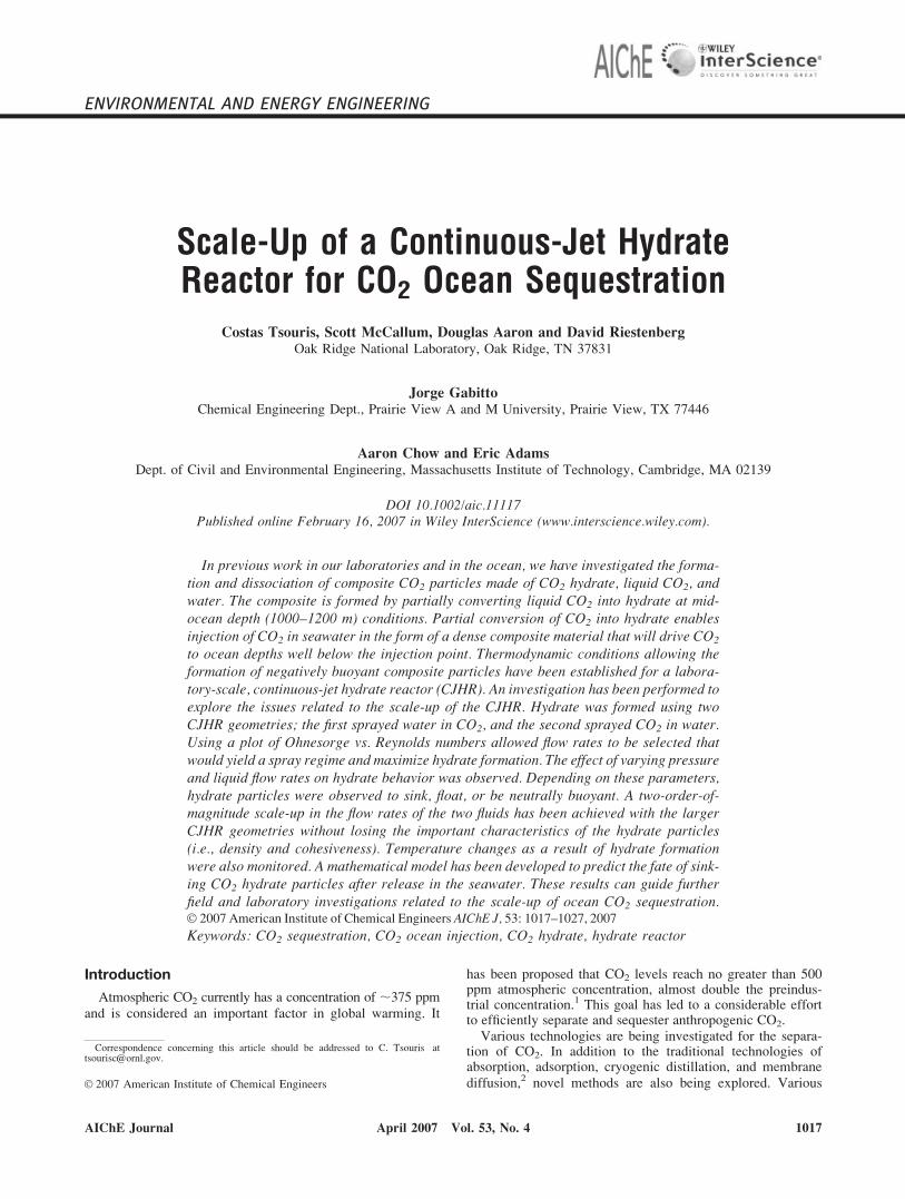
hydrate is a solid crystalline material with a chemical formulaof CO2�n(H2O), where n is the hydration number. Values of6–8 have been reported for n9. The variability in the hydrationnumber is a result of incomplete filling of the cavities formedby hydrogen bonding between water molecules. Using aCJHR, sufficient conversion could be achieved with suitableflow rates of water and CO2 by having a high flow rate ofwater in the small, inner capillary (Figure 1) and a lower flowrate of CO2 in the outer capillary. A sufficiently high flow ofwater establishes a spraying mode, which provides a high sur-face-area-to-volume ratio, aiding conversion of CO2 tohydrate. Theoretically, for complete conversion of CO2 intohydrate, a maximum volumetric flow-rate ratio of ;1:3CO2:H2O is needed based on stoichiometry when n is assumedto take a value of 7.
It was observed by Tang et al.10 and Riestenberg et al.11
that three distinct breakup regimes form depending on theOhnesorge and Reynolds numbers. Low Reynolds numbersresult in the Rayleigh regime, in which uniform-size drops
Figure 1. (a) CJHR receiving water (through the smallcapillary) and liquid CO2 and producing a co-hesive paste-like solid, which is a compositeof CO2 hydrate, unconverted liquid CO2, andunconverted water; (b) CJHR mounted on theseafloor process simulator (SPS).
[Color figure can be viewed in the online issue, which isavailable at www.interscience.wiley.com.]
1018 DOI 10.1002/aic Published on behalf of the AIChE April 2007 Vol. 53, No. 4 AIChE Journal

form from the destabilization of the jet. As the velocity isincreased, transition breakup is observed. This mode is char-acterized by varying-size droplets formed by the jet destabili-zation. Spray mode is achieved at even higher Reynolds num-bers. This mode has been deemed desirable because very finedroplets are formed, increasing the area for hydrate conver-sion. In the work of Riestenberg et al.,11 various small capilla-ries were used with IDs ranging from 127 to 508 mm and out-side diameters (ODs) ranging from 794 to 1588 mm. The flowrates in these experiments were constrained by the limits ofthe syringe pumps, but varied from 0.5 to 25.0 ml/min forboth CO2 and water. Increasing the injector throughputrequired a larger injector size. Riestenberg et al.11 also mea-sured the droplet-size distributions for different injectors andjet breakup modes. A significant observation was that thedroplet size did not increase very much with capillary sizewhen in spray mode (e.g., doubling capillary diameter pro-duced a very small increase in drop size). The composite (liq-uid CO2/CO2 hydrate/water) material that forms in the sprayregime is a cohesive paste-like solid with droplets fused byhydrate.12 The composite has the same diameter as the inter-nal diameter of the injector outlet and frequently breaks toform long, cylindrical particles of 50–100 mm length. A cohe-sive hydrate stream is desirable for aiding in transport of CO2
to the deep ocean.Investigations of sinking hydrate formation continued with
field experiments at Monterey Bay in collaboration with theMonterey Bay Aquarium Research Institute.7,13 Experimentsusing a larger injector (381 mm ID for water and 9.5 mm forCO2) were performed at a depth of ;1200 m. Water and CO2
flow rates were 140–150 ml/min and 26–40 ml/min, respec-tively. A remotely operated vehicle (ROV) was used to followthe movement of particles inside a ‘‘bubble box’’ and observesinking/floating behavior. The bubble box was a large, trans-parent plastic box used to minimize the effect of ocean cur-rents on the hydrate particles, thus producing a relatively qui-escent bulk phase. The motion was, therefore, limited to thevertical direction and controlled by the buoyancy of the par-ticles. The ROV was also equipped with instrumentation to re-cord temperature, pressure, and seawater depth and salinity.The information recorded by the ROV allowed direct estima-tions of terminal velocity (;5 cm/s) and diameter shrinkagerates (4–10 mm/s) for the particles. Estimates of particle den-sity were made from the terminal velocity by assuming amodel for the drag coefficient of freely falling cylinders. Themodel, developed by Isaacs and Thodos,14 had been observedto result in terminal velocities similar to those found usingsynthetic particles in our recent tank experiments.13 Knowingthe particle density as well as the densities of liquid CO2, sea-water, and hydrate allowed determination of the reaction effi-ciency X, which was calculated to be in the range of 30–50%.
This work focuses on scale-up issues of the CJHR withrespect to CO2 ocean injection. It is important that a spray re-gime is maintained to form cohesive and dense particles. Asthe cohesive composite sinks, it slowly dissolves into the sea-water. This slow dissolution allows CO2 to sink to greaterdepths. This paper describes the geometry and configurationfor a two-order-of-magnitude scale-up of the CJHR. Charac-teristics of the composite product (e.g., density and cohesive-ness) are discussed with respect to flow-rate increases associ-ated with geometry changes of the CJHR. Scale-up of the
CJHR required the addition of stronger pumps to the ORNLSeafloor Process Simulator (SPS) and construction of differentinjector geometries. Specific experiments discussed includedetermination of the inner capillary and outer tube diametersof the scaled-up CJHR by using water injected into cyclohex-ane. Cyclohexane was used because it mimics the behavior ofCO2 but can be examined at atmospheric conditions. Furtherexperiments describe the geometry of two types of CJHRs, thefirst being a single-capillary concentric CJHR and the secondbeing a capillary-array CJHR. Plume modeling to investigatethe behavior of a sinking CO2 hydrate composite plume isalso described. Finally, a case study examines scale-up issuesconcerning the ocean sequestration of CO2 from one full-sizedpower plant.
Experimental Methods
Experiments were performed in the ORNL SPS.15 The SPSis a 72-l high-pressure (20 MPa) vessel made of Hastelloy C-22 metal with an internal diameter of 0.32 m and internalheight of 0.91 m (Figure 2). The vessel is kept in a 2.5 m �2.5 m � 2.1 m (height) refrigerated cold room equipped tomaintain the desired experimental temperature. Sapphireviewing ports provide opportunities for visual observation,while various access ports allow for temperature and pressureinstrumentation. The CJHR geometry in previous experimentsincluded an inner tube of 1.6-mm OD and 127- to 508-mm IDand an outer tube of 9.5-mm OD and 6.4-mm ID. Water flowrates for these experiments were approximately 25 ml/min,
Figure 2. The ORNL SPS is a 72-l pressure vessel withmultiple observation windows and variousports for instrumentation.
[Color figure can be viewed in the online issue, which isavailable at www.interscience.wiley.com.]
AIChE Journal April 2007 Vol. 53, No. 4 Published on behalf of the AIChE DOI 10.1002/aic 1019
while CO2 was injected at flow rates in the range of 5–10 ml/min. A sinking composite was achieved when the flow ofwater was approximately four times greater than the flow ofCO2. Hydrate-forming conditions for these experiments werein the proximity of 10 MPa and 48C.8,12
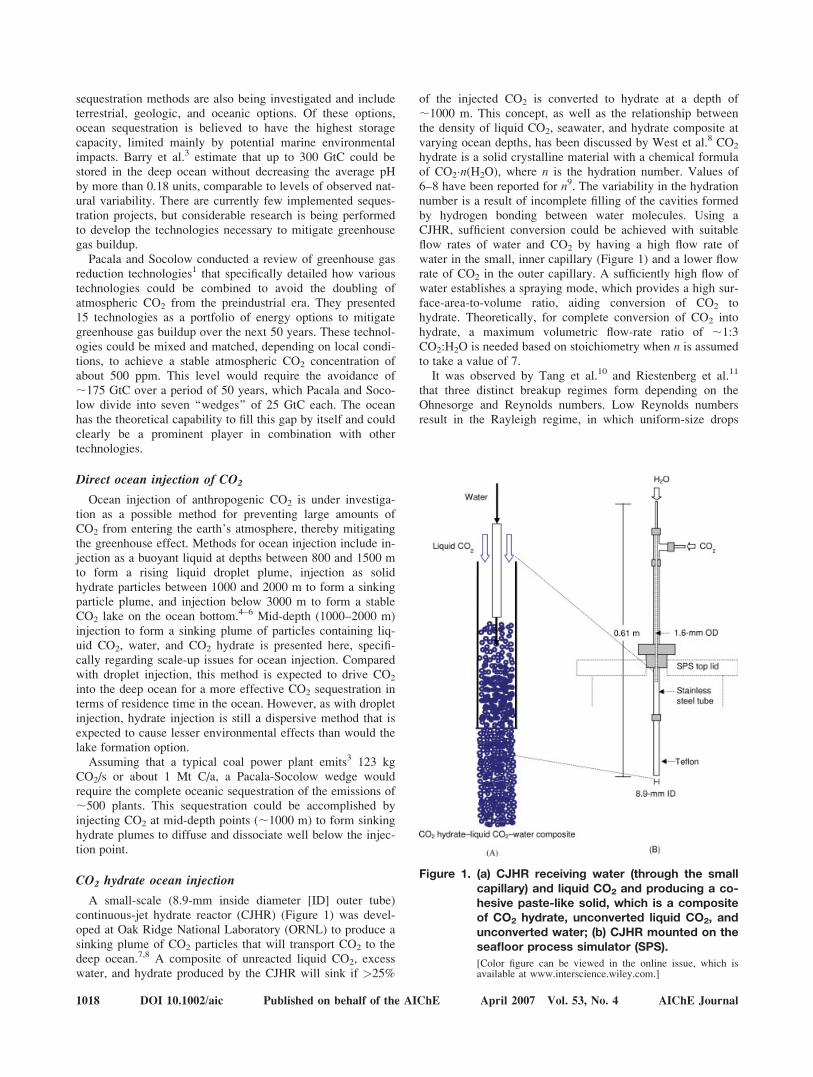
A new, larger CJHR with a stainless steel, 4.0-mm ID and6.35-mm OD inner tube and a Teflon1 25.4-mm OD outertube has been constructed. The length of the reactor from thetip of the inner tube to the tip of the outer tube is ;0.61 m(Figure 3a). In addition to the single injector CJHR, a multipleco-flowing injector-array CJHR was designed with the objec-tive of better distributing the dispersed phase in the continu-ous phase. The multiple injector array had six 1.6-mm IDchannels (Figure 3b). These channels were evenly spacedabout the circumference of the cross section of the outer tube.Both the single- and multiple-capillary CJHR used similarwater and CO2 flow rates for the sake of comparison.
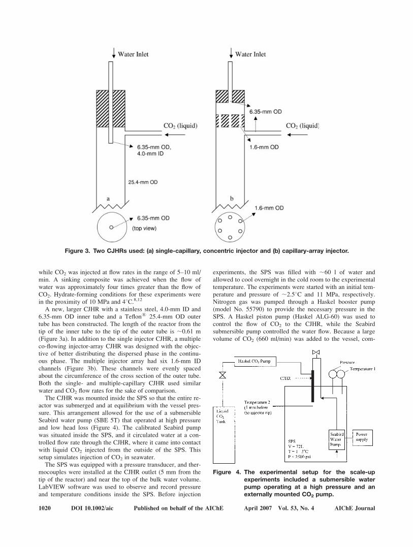
The CJHR was mounted inside the SPS so that the entire re-actor was submerged and at equilibrium with the vessel pres-sure. This arrangement allowed for the use of a submersibleSeabird water pump (SBE 5T) that operated at high pressureand low head loss (Figure 4). The calibrated Seabird pumpwas situated inside the SPS, and it circulated water at a con-trolled flow rate through the CJHR, where it came into contactwith liquid CO2 injected from the outside of the SPS. Thissetup simulates injection of CO2 in seawater.
The SPS was equipped with a pressure transducer, and ther-mocouples were installed at the CJHR outlet (5 mm from thetip of the reactor) and near the top of the bulk water volume.LabVIEW software was used to observe and record pressureand temperature conditions inside the SPS. Before injection
experiments, the SPS was filled with ;60 l of water andallowed to cool overnight in the cold room to the experimentaltemperature. The experiments were started with an initial tem-perature and pressure of ;2.58C and 11 MPa, respectively.Nitrogen gas was pumped through a Haskel booster pump(model No. 55790) to provide the necessary pressure in theSPS. A Haskel piston pump (Haskel ALG-60) was used tocontrol the flow of CO2 to the CJHR, while the Seabirdsubmersible pump controlled the water flow. Because a largevolume of CO2 (660 ml/min) was added to the vessel, com-
Figure 3. Two CJHRs used: (a) single-capillary, concentric injector and (b) capillary-array injector.
Figure 4. The experimental setup for the scale-upexperiments included a submersible waterpump operating at a high pressure and anexternally mounted CO2 pump.
1020 DOI 10.1002/aic Published on behalf of the AIChE April 2007 Vol. 53, No. 4 AIChE Journal
pressed gas had to be manually vented periodically to main-tain the desired pressure in the vessel. This pressure buildupand subsequent venting caused the pressure to vary between11 and 11.7 MPa.
The scale-up experiments were video-recorded with aSonyTM FireWire (XCD-X710CR) camera connected to a per-sonal computer and also observed with a Sony Handycam1
(CCD-TR716). Fiber-optic lighting with focusing lenses pro-vided light for the interior, while a white backdrop reducedglare from the metal walls. The 25.4-mm OD CJHR wasplaced vertically in the SPS and attached to the submersiblewater pump inside the vessel and to the CO2 source throughaccess ports on the side of the vessel. The injector was posi-tioned such that the Sony camera could record the hydrateexiting the reactor.
Results and Discussion
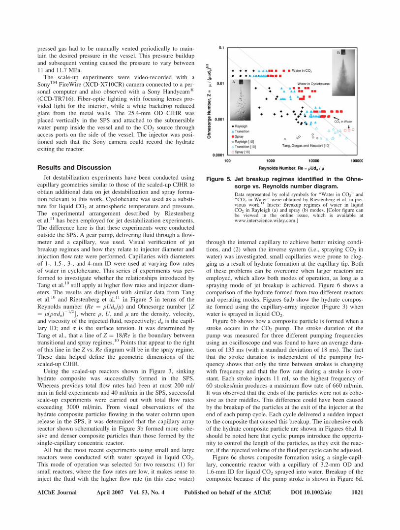
Jet destabilization experiments have been conducted usingcapillary geometries similar to those of the scaled-up CJHR toobtain additional data on jet destabilization and spray forma-tion relevant to this work. Cyclohexane was used as a substi-tute for liquid CO2 at atmospheric temperature and pressure.The experimental arrangement described by Riestenberget al.11 has been employed for jet destabilization experiments.The difference here is that these experiments were conductedoutside the SPS. A gear pump, delivering fluid through a flow-meter and a capillary, was used. Visual verification of jetbreakup regimes and how they relate to injector diameter andinjection flow rate were performed. Capillaries with diametersof 1-, 1.5-, 3-, and 4-mm ID were used at varying flow ratesof water in cyclohexane. This series of experiments was per-formed to investigate whether the relationships introduced byTang et al.10 still apply at higher flow rates and injector diam-eters. The results are displayed with similar data from Tanget al.10 and Riestenberg et al.11 in Figure 5 in terms of theReynolds number (Re ¼ rUdo/m) and Ohnesorge number bZ¼ m(rsdo)
�1/2c, where r, U, and m are the density, velocity,and viscosity of the injected fluid, respectively; do is the capil-lary ID; and s is the surface tension. It was determined byTang et al., that a line of Z ¼ 18/Re is the boundary betweentransitional and spray regimes.10 Points that appear to the rightof this line in the Z vs. Re diagram will be in the spray regime.These data helped define the geometric dimensions of thescaled-up CJHR.
Using the scaled-up reactors shown in Figure 3, sinkinghydrate composite was successfully formed in the SPS.Whereas previous total flow rates had been at most 200 ml/min in field experiments and 40 ml/min in the SPS, successfulscale-up experiments were carried out with total flow ratesexceeding 3000 ml/min. From visual observations of thehydrate composite particles flowing in the water column uponrelease in the SPS, it was determined that the capillary-arrayreactor shown schematically in Figure 3b formed more cohe-sive and denser composite particles than those formed by thesingle-capillary concentric reactor.
All but the most recent experiments using small and largereactors were conducted with water sprayed in liquid CO2.This mode of operation was selected for two reasons: (1) forsmall reactors, where the flow rates are low, it makes sense toinject the fluid with the higher flow rate (in this case water)
through the internal capillary to achieve better mixing condi-tions, and (2) when the inverse system (i.e., spraying CO2 inwater) was investigated, small capillaries were prone to clog-ging as a result of hydrate formation at the capillary tip. Bothof these problems can be overcome when larger reactors areemployed, which allow both modes of operation, as long as aspraying mode of jet breakup is achieved. Figure 6 shows acomparison of the hydrate formed from two different reactorsand operating modes. Figures 6a,b show the hydrate compos-ite formed using the capillary-array injector (Figure 3) whenwater is sprayed in liquid CO2.
Figure 6b shows how a composite particle is formed when astroke occurs in the CO2 pump. The stroke duration of thepump was measured for three different pumping frequenciesusing an oscilloscope and was found to have an average dura-tion of 135 ms (with a standard deviation of 18 ms). The factthat the stroke duration is independent of the pumping fre-quency shows that only the time between strokes is changingwith frequency and that the flow rate during a stroke is con-stant. Each stroke injects 11 ml, so the highest frequency of60 strokes/min produces a maximum flow rate of 660 ml/min.It was observed that the ends of the particles were not as cohe-sive as their middles. This difference could have been causedby the breakup of the particles at the exit of the injector at theend of each pump cycle. Each cycle delivered a sudden impactto the composite that caused this breakup. The incohesive endsof the hydrate composite particle are shown in Figures 6b,d. Itshould be noted here that cyclic pumps introduce the opportu-nity to control the length of the particles, as they exit the reac-tor, if the injected volume of the fluid per cycle can be adjusted.
Figure 6c shows composite formation using a single-capil-lary, concentric reactor with a capillary of 3.2-mm OD and1.6-mm ID for liquid CO2 sprayed into water. Breakup of thecomposite because of the pump stroke is shown in Figure 6d.
Figure 5. Jet breakup regimes identified in the Ohne-sorge vs. Reynolds number diagram.
Data represented by solid symbols for ‘‘Water in CO2’’ and‘‘CO2 in Water’’ were obtained by Riestenberg et al. in pre-vious work.11 Insets: Breakup regimes of water in liquidCO2 in Rayleigh (a) and spray (b) modes. [Color figure canbe viewed in the online issue, which is available atwww.interscience.wiley.com.]
AIChE Journal April 2007 Vol. 53, No. 4 Published on behalf of the AIChE DOI 10.1002/aic 1021
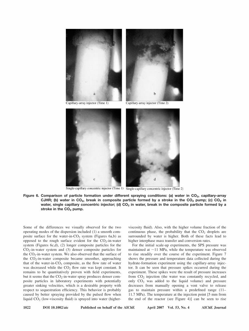
Some of the differences we visually observed for the twooperating modes of the dispersion included (1) a smooth com-posite surface for the water-in-CO2 system (Figures 6a,b) asopposed to the rough surface evident for the CO2-in-watersystem (Figures 6c,d), (2) longer composite particles for theCO2-in-water system and (3) denser composite particles forthe CO2-in-water system. We also observed that the surface ofthe CO2-in-water composite became smoother, approachingthat of the water-in-CO2 composite, as the flow rate of waterwas decreased while the CO2 flow rate was kept constant. Itremains to be quantitatively proven with field experiments,but it seems that the CO2-in-water spray produces denser com-posite particles in laboratory experiments with potentiallygreater sinking velocities, which is a desirable property withrespect to sequestration efficiency. This behavior is probablycaused by better spraying provided by the pulsed flow whenliquid CO2 (low-viscosity fluid) is sprayed into water (higher-
viscosity fluid). Also, with the higher volume fraction of thecontinuous phase, the probability that the CO2 droplets aresurrounded by water is higher. Both of these facts lead tohigher interphase mass transfer and conversion rates.
For the initial scale-up experiments, the SPS pressure wasmaintained at ;11 MPa, while the temperature was observedto rise steadily over the course of the experiment. Figure 7shows the pressure and temperature data collected during thehydrate-formation experiment using the capillary-array injec-tor. It can be seen that pressure spikes occurred during theexperiment. These spikes were the result of pressure increasesfrom CO2 injection (the water was constantly recycled, andonly CO2 was added to the liquid volume) and pressuredecreases from manually opening a vent valve to releasegas to maintain pressure within a predefined range (11–11.7 MPa). The temperature at the injection point [5 mm fromthe end of the reactor (see Figure 4)] can be seen to rise
Figure 6. Comparison of particle formation under different spraying conditions: (a) water in CO2, capillary-arrayCJHR; (b) water in CO2, break in composite particle formed by a stroke in the CO2 pump; (c) CO2 inwater, single capillary concentric injector; (d) CO2 in water, break in the composite particle formed by astroke in the CO2 pump.
1022 DOI 10.1002/aic Published on behalf of the AIChE April 2007 Vol. 53, No. 4 AIChE Journal
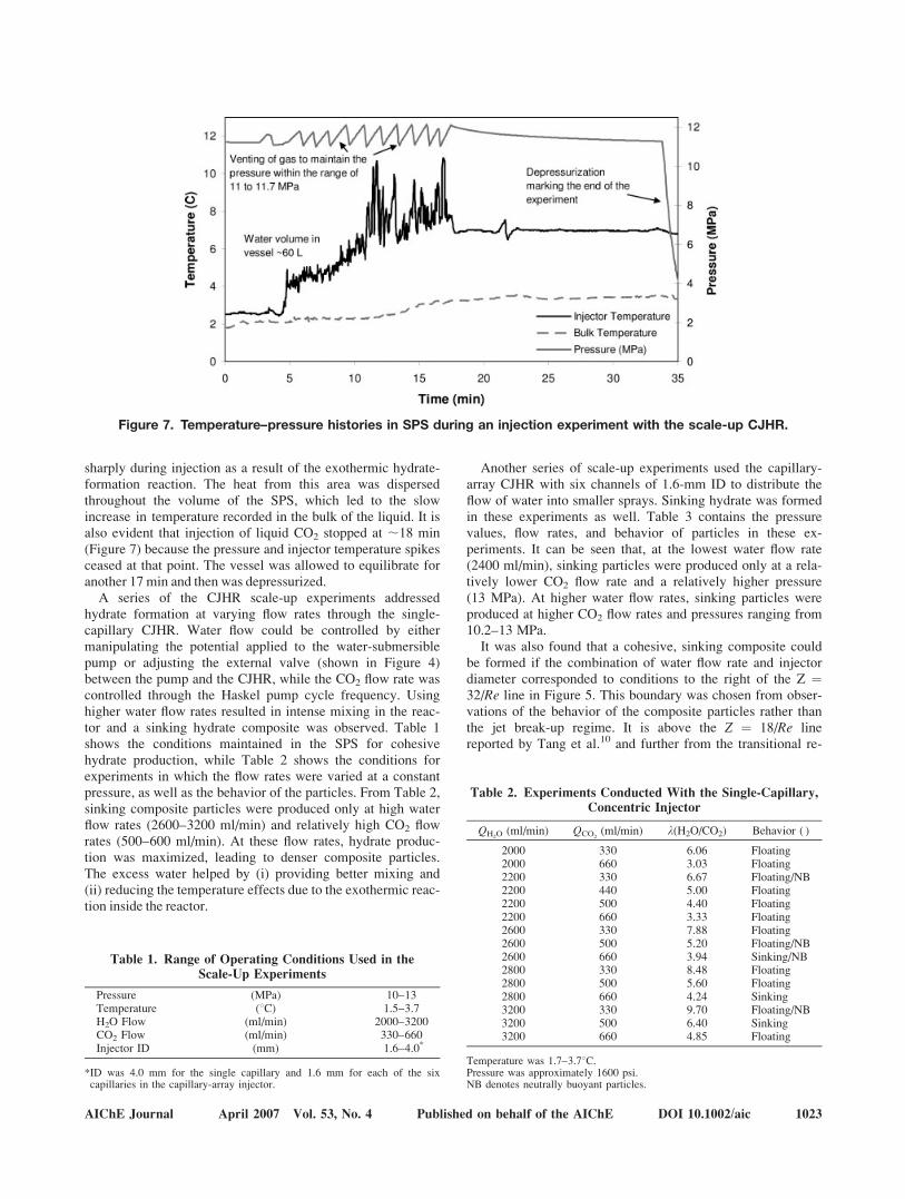
sharply during injection as a result of the exothermic hydrate-formation reaction. The heat from this area was dispersedthroughout the volume of the SPS, which led to the slowincrease in temperature recorded in the bulk of the liquid. It isalso evident that injection of liquid CO2 stopped at ;18 min(Figure 7) because the pressure and injector temperature spikesceased at that point. The vessel was allowed to equilibrate foranother 17 min and then was depressurized.
A series of the CJHR scale-up experiments addressedhydrate formation at varying flow rates through the single-capillary CJHR. Water flow could be controlled by eithermanipulating the potential applied to the water-submersiblepump or adjusting the external valve (shown in Figure 4)between the pump and the CJHR, while the CO2 flow rate wascontrolled through the Haskel pump cycle frequency. Usinghigher water flow rates resulted in intense mixing in the reac-tor and a sinking hydrate composite was observed. Table 1shows the conditions maintained in the SPS for cohesivehydrate production, while Table 2 shows the conditions forexperiments in which the flow rates were varied at a constantpressure, as well as the behavior of the particles. From Table 2,sinking composite particles were produced only at high waterflow rates (2600–3200 ml/min) and relatively high CO2 flowrates (500–600 ml/min). At these flow rates, hydrate produc-tion was maximized, leading to denser composite particles.The excess water helped by (i) providing better mixing and(ii) reducing the temperature effects due to the exothermic reac-tion inside the reactor.
Another series of scale-up experiments used the capillary-array CJHR with six channels of 1.6-mm ID to distribute theflow of water into smaller sprays. Sinking hydrate was formedin these experiments as well. Table 3 contains the pressurevalues, flow rates, and behavior of particles in these ex-periments. It can be seen that, at the lowest water flow rate(2400 ml/min), sinking particles were produced only at a rela-tively lower CO2 flow rate and a relatively higher pressure(13 MPa). At higher water flow rates, sinking particles wereproduced at higher CO2 flow rates and pressures ranging from10.2–13 MPa.
It was also found that a cohesive, sinking composite couldbe formed if the combination of water flow rate and injectordiameter corresponded to conditions to the right of the Z ¼32/Re line in Figure 5. This boundary was chosen from obser-vations of the behavior of the composite particles rather thanthe jet break-up regime. It is above the Z ¼ 18/Re linereported by Tang et al.10 and further from the transitional re-
Figure 7. Temperature–pressure histories in SPS during an injection experiment with the scale-up CJHR.
Table 1. Range of Operating Conditions Used in theScale-Up Experiments
Pressure (MPa) 10–13Temperature (8C) 1.5–3.7H2O Flow (ml/min) 2000–3200CO2 Flow (ml/min) 330–660Injector ID (mm) 1.6–4.0*
*ID was 4.0 mm for the single capillary and 1.6 mm for each of the sixcapillaries in the capillary-array injector.
Table 2. Experiments Conducted With the Single-Capillary,Concentric Injector
QH2O(ml/min) QCO2
(ml/min) l(H2O/CO2) Behavior ( )
2000 330 6.06 Floating2000 660 3.03 Floating2200 330 6.67 Floating/NB2200 440 5.00 Floating2200 500 4.40 Floating2200 660 3.33 Floating2600 330 7.88 Floating2600 500 5.20 Floating/NB2600 660 3.94 Sinking/NB2800 330 8.48 Floating2800 500 5.60 Floating2800 660 4.24 Sinking3200 330 9.70 Floating/NB3200 500 6.40 Sinking3200 660 4.85 Floating
Temperature was 1.7–3.78C.Pressure was approximately 1600 psi.NB denotes neutrally buoyant particles.
AIChE Journal April 2007 Vol. 53, No. 4 Published on behalf of the AIChE DOI 10.1002/aic 1023
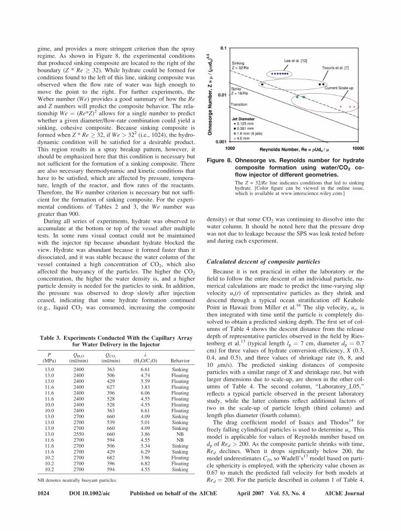
gime, and provides a more stringent criterion than the sprayregime. As shown in Figure 8, the experimental conditionsthat produced sinking composite are located to the right of theboundary (Z * Re � 32). While hydrate could be formed forconditions found to the left of this line, sinking composite wasobserved when the flow rate of water was high enough tomove the point to the right. For further experiments, theWeber number (We) provides a good summary of how the Reand Z numbers will predict the composite behavior. The rela-tionship We ¼ (Re*Z)2 allows for a single number to predictwhether a given diameter/flow-rate combination could yield asinking, cohesive composite. Because sinking composite isformed when Z * Re � 32, if We > 322 (i.e., 1024), the hydro-dynamic condition will be satisfied for a desirable product.This region results in a spray breakup pattern, however, itshould be emphasized here that this condition is necessary butnot sufficient for the formation of a sinking composite. Thereare also necessary thermodynamic and kinetic conditions thathave to be satisfied, which are affected by pressure, tempera-ture, length of the reactor, and flow rates of the reactants.Therefore, the We number criterion is necessary but not suffi-cient for the formation of sinking composite. For the experi-mental conditions of Tables 2 and 3, the We number wasgreater than 900.
During all series of experiments, hydrate was observed toaccumulate at the bottom or top of the vessel after multipletests. In some runs visual contact could not be maintainedwith the injector tip because abundant hydrate blocked theview. Hydrate was abundant because it formed faster than itdissociated, and it was stable because the water column of thevessel contained a high concentration of CO2, which alsoaffected the buoyancy of the particles. The higher the CO2
concentration, the higher the water density is, and a higherparticle density is needed for the particles to sink. In addition,the pressure was observed to drop slowly after injectionceased, indicating that some hydrate formation continued(e.g., liquid CO2 was consumed, increasing the composite
density) or that some CO2 was continuing to dissolve into thewater column. It should be noted here that the pressure dropwas not due to leakage because the SPS was leak tested beforeand during each experiment.
Calculated descent of composite particles
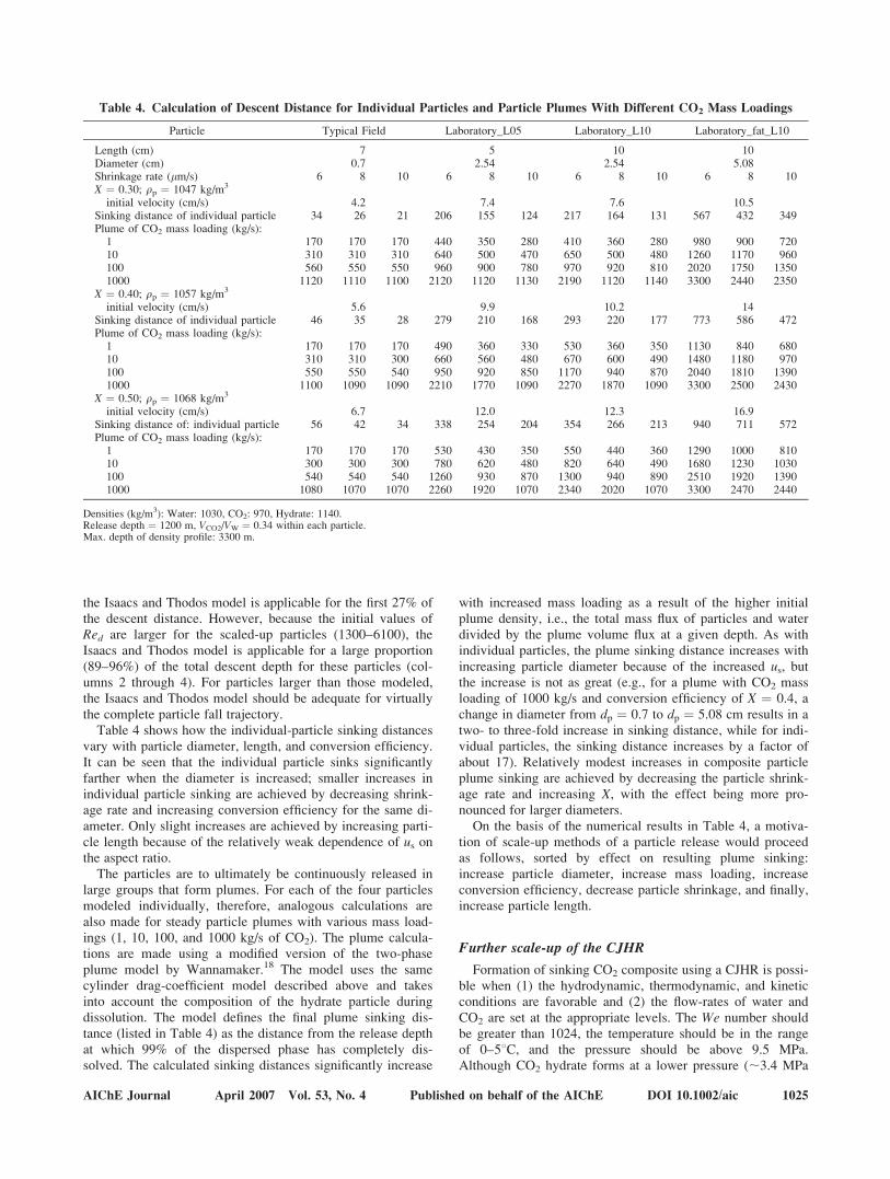
Because it is not practical in either the laboratory or thefield to follow the entire descent of an individual particle, nu-merical calculations are made to predict the time-varying slipvelocity us(t) of representative particles as they shrink anddescend through a typical ocean stratification off KeaholePoint in Hawaii from Miller et al.16 The slip velocity, us, isthen integrated with time until the particle is completely dis-solved to obtain a predicted sinking depth. The first set of col-umns of Table 4 shows the descent distance from the releasedepth of representative particles observed in the field by Ries-tenberg et al.13 (typical length lp ¼ 7 cm, diameter dp ¼ 0.7cm) for three values of hydrate conversion efficiency, X (0.3,0.4, and 0.5), and three values of shrinkage rate (6, 8, and10 mm/s). The predicted sinking distances of compositeparticles with a similar range of X and shrinkage rate, but withlarger dimensions due to scale-up, are shown in the other col-umns of Table 4. The second column, ‘‘Laboratory_L05,’’reflects a typical particle observed in the present laboratorystudy, while the latter columns reflect additional factors oftwo in the scale-up of particle length (third column) andlength plus diameter (fourth column).
The drag coefficient model of Isaacs and Thodos14 forfreely falling cylindrical particles is used to determine us. Thismodel is applicable for values of Reynolds number based ondp of Red > 200. As the composite particle shrinks with time,Red declines. When it drops significantly below 200, themodel underestimates CD, so Wadell’s17 model based on parti-cle sphericity is employed, with the sphericity value chosen as0.67 to match the predicted fall velocity for both models atRed ¼ 200. For the particle described in column 1 of Table 4,
Table 3. Experiments Conducted With the Capillary Arrayfor Water Delivery in the Injector
P(MPa)
QH2O
(ml/min)QCO2
(ml/min)l
(H2O/C2O) Behavior
13.0 2400 363 6.61 Sinking13.0 2400 506 4.74 Floating13.0 2400 429 5.59 Floating11.6 2400 627 3.83 Floating11.6 2400 396 6.06 Floating11.6 2400 528 4.55 Floating10.0 2400 528 4.55 Floating10.0 2400 363 6.61 Floating13.0 2700 660 4.09 Sinking13.0 2700 539 5.01 Sinking13.0 2700 660 4.09 Sinking13.0 2550 660 3.86 NB11.6 2700 594 4.55 NB11.6 2700 506 5.34 Sinking11.6 2700 429 6.29 Sinking10.2 2700 682 3.96 Floating10.2 2700 396 6.82 Floating10.2 2700 594 4.55 Sinking
NB denotes neutrally buoyant particles.
Figure 8. Ohnesorge vs. Reynolds number for hydratecomposite formation using water/CO2 co-flow injector of different geometries.
The Z = 32/Re line indicates conditions that led to sinkinghydrate. [Color figure can be viewed in the online issue,which is available at www.interscience.wiley.com.]
1024 DOI 10.1002/aic Published on behalf of the AIChE April 2007 Vol. 53, No. 4 AIChE Journal
the Isaacs and Thodos model is applicable for the first 27% ofthe descent distance. However, because the initial values ofRed are larger for the scaled-up particles (1300–6100), theIsaacs and Thodos model is applicable for a large proportion(89–96%) of the total descent depth for these particles (col-umns 2 through 4). For particles larger than those modeled,the Isaacs and Thodos model should be adequate for virtuallythe complete particle fall trajectory.
Table 4 shows how the individual-particle sinking distancesvary with particle diameter, length, and conversion efficiency.It can be seen that the individual particle sinks significantlyfarther when the diameter is increased; smaller increases inindividual particle sinking are achieved by decreasing shrink-age rate and increasing conversion efficiency for the same di-ameter. Only slight increases are achieved by increasing parti-cle length because of the relatively weak dependence of us onthe aspect ratio.
The particles are to ultimately be continuously released inlarge groups that form plumes. For each of the four particlesmodeled individually, therefore, analogous calculations arealso made for steady particle plumes with various mass load-ings (1, 10, 100, and 1000 kg/s of CO2). The plume calcula-tions are made using a modified version of the two-phaseplume model by Wannamaker.18 The model uses the samecylinder drag-coefficient model described above and takesinto account the composition of the hydrate particle duringdissolution. The model defines the final plume sinking dis-tance (listed in Table 4) as the distance from the release depthat which 99% of the dispersed phase has completely dis-solved. The calculated sinking distances significantly increase
with increased mass loading as a result of the higher initialplume density, i.e., the total mass flux of particles and waterdivided by the plume volume flux at a given depth. As withindividual particles, the plume sinking distance increases withincreasing particle diameter because of the increased us, butthe increase is not as great (e.g., for a plume with CO2 massloading of 1000 kg/s and conversion efficiency of X ¼ 0.4, achange in diameter from dp ¼ 0.7 to dp ¼ 5.08 cm results in atwo- to three-fold increase in sinking distance, while for indi-vidual particles, the sinking distance increases by a factor ofabout 17). Relatively modest increases in composite particleplume sinking are achieved by decreasing the particle shrink-age rate and increasing X, with the effect being more pro-nounced for larger diameters.
On the basis of the numerical results in Table 4, a motiva-tion of scale-up methods of a particle release would proceedas follows, sorted by effect on resulting plume sinking:increase particle diameter, increase mass loading, increaseconversion efficiency, decrease particle shrinkage, and finally,increase particle length.
Further scale-up of the CJHR
Formation of sinking CO2 composite using a CJHR is possi-ble when (1) the hydrodynamic, thermodynamic, and kineticconditions are favorable and (2) the flow-rates of water andCO2 are set at the appropriate levels. The We number shouldbe greater than 1024, the temperature should be in the rangeof 0–58C, and the pressure should be above 9.5 MPa.Although CO2 hydrate forms at a lower pressure (;3.4 MPa
Table 4. Calculation of Descent Distance for Individual Particles and Particle Plumes With Different CO2 Mass Loadings
Particle Typical Field Laboratory_L05 Laboratory_L10 Laboratory_fat_L10
Length (cm) 7 5 10 10Diameter (cm) 0.7 2.54 2.54 5.08Shrinkage rate (mm/s) 6 8 10 6 8 10 6 8 10 6 8 10X ¼ 0.30; rp ¼ 1047 kg/m3
initial velocity (cm/s) 4.2 7.4 7.6 10.5Sinking distance of individual particle 34 26 21 206 155 124 217 164 131 567 432 349Plume of CO2 mass loading (kg/s):1 170 170 170 440 350 280 410 360 280 980 900 72010 310 310 310 640 500 470 650 500 480 1260 1170 960100 560 550 550 960 900 780 970 920 810 2020 1750 13501000 1120 1110 1100 2120 1120 1130 2190 1120 1140 3300 2440 2350
X ¼ 0.40; rp ¼ 1057 kg/m3
initial velocity (cm/s) 5.6 9.9 10.2 14Sinking distance of individual particle 46 35 28 279 210 168 293 220 177 773 586 472Plume of CO2 mass loading (kg/s):1 170 170 170 490 360 330 530 360 350 1130 840 68010 310 310 300 660 560 480 670 600 490 1480 1180 970100 550 550 540 950 920 850 1170 940 870 2040 1810 13901000 1100 1090 1090 2210 1770 1090 2270 1870 1090 3300 2500 2430
X ¼ 0.50; rp ¼ 1068 kg/m3
initial velocity (cm/s) 6.7 12.0 12.3 16.9Sinking distance of: individual particle 56 42 34 338 254 204 354 266 213 940 711 572Plume of CO2 mass loading (kg/s):1 170 170 170 530 430 350 550 440 360 1290 1000 81010 300 300 300 780 620 480 820 640 490 1680 1230 1030100 540 540 540 1260 930 870 1300 940 890 2510 1920 13901000 1080 1070 1070 2260 1920 1070 2340 2020 1070 3300 2470 2440
Densities (kg/m3): Water: 1030, CO2: 970, Hydrate: 1140.Release depth ¼ 1200 m, VCO2/VW ¼ 0.34 within each particle.Max. depth of density profile: 3300 m.
AIChE Journal April 2007 Vol. 53, No. 4 Published on behalf of the AIChE DOI 10.1002/aic 1025
at 8.48C), a higher pressure (>9.5 MPa) is needed to producea sinking composite. The reason for this is that at a higherpressure, liquid CO2 (which is compressible) becomes denser,adding to the density of the composite.
Observations suggest that it is reasonable to assume a flowrate of water at least four times larger than that of CO2. Forthe scale-up of a single reactor, it is important to consider theflow rate of the composite and the spacing of the numerousadjacent reactors. Plume modeling can help to determine thescale-up design. For a single reactor, the mass flow rates ofliquid CO2 and water are defined. The option is then to oper-ate the reactor in CO2-in-water mode or water-in-CO2 mode.To determine the preferred mode, field experiments for theCO2-in-water spray mode will be compared with the compos-ite density and dissolution rate of the water-in-CO2 mode. Af-ter the mode is selected, the number of capillaries needed todistribute the dispersed fluid into the continuous phase will bedetermined. A higher conversion of liquid CO2 into hydrate isaided by a good spatial distribution of the dispersed phase,while jet breakup occurs in the spray mode.
The recommended strategy is to assume a hexagonal con-figuration for the internal capillary array, with six capillarieslocated at the angles of a hexagon and at equal distance fromthe center and the internal surface of the outer tube. A seventhcapillary will be located at the center of the hexagon. Thediameters of all the capillaries will be the same. Using theknown flow rate of the injected fluid through the capillaries(Qd) and the Weber number criterion for a specific spraymode results in Eqs. 1 and 2 below:
We ¼ ðRe � ZÞ2 ¼ rd u2 do=s � 1024 (1)
u ¼ 4Qd=ð7pdo2Þðfor seven capillariesÞ; (2)
where rd is the density of the dispersed fluid. From theserelationships, the capillary diameter for a spray mode isdefined as shown in Eq. 3 below.
do � 0:032 ðrdQd2=sÞ1=3 (3)
The internal diameter of the CJHR outlet tube can be deter-mined as twice the distance between the center of the hexago-nal capillary array and each of the angles. The length of theouter tube is such that the residence time of the fluid in theCJHR is ;5 s. By determining the configuration of the capil-lary array, the diameter of each capillary, the diameter of theoutlet tube, and the length of the reactor, we have geometri-cally defined the CJHR for a given set of liquid CO2 andwater flow rates so that a sinking composite can be producedat intermediate ocean depths. This approach can be employedin scaling up the reactor for any set of flow rates.
Sequestration case study for one coal power plant
Preliminary estimations of what would be required for thesequestration of one coal power plant have been performed.Assuming the average power plant emits 123 kg CO2/s (about1 MtC/a), approximately 740 capillary-array CJHR units with8.9-mm ID (for each of the seven capillaries) would berequired for sequestration of all the CO2 produced by that
plant. This number is based on Eq. 3 for a continuous opera-tion. The flow rate of CO2 was determined using the CO2 den-sity at 1100 m depth and 48C. Then, the flow of water was setto be four times that of CO2 for optimum hydrate conversion.
Summary and Conclusions
We have developed and scaled-up a CJHR to convert liquidCO2 and seawater to CO2 hydrate and, thus, form a densecomposite material at intermediate ocean depths. This materialcontains unconverted liquid CO2, unconverted seawater, andhydrate and is expected to drive CO2 well below the injectionpoint for a more effective sequestration of CO2 in the ocean.The reactor intimately combines liquid CO2 with surroundingseawater in a mixing zone in which one phase is sprayed intothe other. The drops of the sprayed phase fuse to each otherby hydrate, generating a cohesive composite material that,depending on the conversion fraction of liquid CO2 to hydrate,can be denser than the seawater and sink toward the bottom ofthe ocean.
Because of hydrate formation in the internal capillary ofthe reactor in the case of spraying liquid CO2 into water insmall CJHR geometries, this operation mode led to cloggingproblems and therefore was not successful. However, in thescaled-up reactor, where the ID of the capillary was signifi-cantly larger, both spraying modes were successful in pro-ducing composite particles denser than the surrounding sea-water. In fact, based on visual observations, spraying CO2 inwater produced denser particles, which is believed to be theresult of better spraying of the lower-viscosity fluid under apulsed flow. This observation, as well as the dissolution rateof the particles, should be further investigated in fieldexperiments.
On the basis of dimensionless analysis of the various jetdestabilization regimes in the CJHR, a relationship has beenderived (see Eq. 2) that relates the orifice-limiting diameter ofthe capillary to the physical properties and flow rates of thedispersed fluid so a dense composite can be produced. Thisrelationship constitutes a necessary but not sufficient conditionfor the formation of sinking hydrate composite and can beused in scaling up the reactor. Additional thermodynamic andkinetic conditions are also necessary for sinking composite tobe produced. Dissolution modeling described the history ofparticle diameter and terminal velocity and the depth of com-plete dissolution after injection.
A case study of ocean sequestration of CO2 produced by asingle power plant has also been discussed. An average plantproducing 123 kg CO2/s would require 740 CJHR units. Eachunit would consist of a seven-capillary array, and each capil-lary would have an ID of 8.9 mm. This number of reactorswould require additional work to determine the geometricconfiguration and spacing among the reactors based on plumemodeling studies. Plume modeling also provides a clearer pic-ture of the fate of composite particles as compared with mod-eling of individual particles. It is estimated that plume effectswould allow particles to sink much deeper than individual par-ticles before complete dissolution. As a recommendation forfuture work, field experiments are needed to further investi-gate the performance of an individual scaled-up reactor andobserve the onset and the sinking behavior of plumes of com-posite particles produced by arrays of CJHRs.
1026 DOI 10.1002/aic Published on behalf of the AIChE April 2007 Vol. 53, No. 4 AIChE Journal
Acknowledgments
Gratefully acknowledged is support by the Ocean Carbon Sequestra-tion Program, Office of Biological and Environmental Research, U.S.Department of Energy under Contract No. DE-AC05-00OR22725 withUT-Battelle, LLC. The authors are thankful to Tommy Phelps and Phil-lip Szymcek for valuable discussions and Ms. P. P. Henson for editingthe manuscript.
Literature Cited
1. Pacala S, Socolow R. Stabilization wedges: solving the climate prob-lem for the next 50 years with current technologies. Science. 2004;305:968–972.
2. Meisen A, Shuai X. Research and development issues in CO2 cap-ture. Energy Convers Manage. 1997;38(Suppl.):S37–S42.
3. Barry J, Adams E, Bleck R, Caldeira K, Carman K, Erickson D,Kennett J, McLain C, Sarmiento J, Tsouris C. Ecosystem and soci-etal consequences of ocean versus atmospheric carbon storage. Pre-sentation to American Geophysical Union, San Francisco, Decem-ber 2005.
4. Medina M-G, Bond GM, Stringer J. An overview of carbon dioxidesequestration. The Electrochemical Society’s Interface. 2001;10:26–30.
5. Hoffert MI, Caldeira K, Benford G, Criswell DR, Green C, HerzogH, Jain AK, Kheshgi HS, Lackner KS, Lewis JS, Lightfoot HD,Manheimer W, Mankins JC, Mauel ME, Perkins LJ, SchlesingerME, Volk T, Wigley TML. Advanced technology paths to global cli-mate stability: Energy for a greenhouse planet. Science. 2002;298:981–987.
6. Brewer PG, Friederich G, Peltzer ET, Orr FM Jr. Direct experimentson the ocean disposal of fossil fuel CO2. Science. 1999;284:943–945.
7. Tsouris C, Brewer P, Peltzer E, Walz P, Riestenberg D, Liang L,West OR. Hydrate composite particles for ocean carbon seques-tration: field verification. Environ Sci Technol. 2004;38:2470–2475.
8. West OR, Tsouris C, Lee S, McCallum S. Negatively buoyant CO2-hydrate composite for ocean carbon sequestration. AIChE J. 2003;49:283–285.
9. Holder GD, Gugini AV, Warzinski RP. Modeling Clathrate hydrateformation during carbon dioxide injection into the ocean. EnvironSci Technol. 1995;29:276.
10. Tang L, Gorgas TJ, Masutani SM. Liquid CO2 Droplet Spectra. InProceedings of the Sixth International Conference on GreenhouseGas Control Technologies. Trondheim, Norway. 19–22 June, 2002.
11. Riestenberg D, Chiu E, Gborigi M, Liang L, West OR, Tsouris C.Investigation of jet breakup and droplet size distribution of liquidCO2 and water systems-implications for CO2 hydrate formation forocean carbon sequestration. Am Mineral. 2004;89:1240–1246.
12. Lee S, Liang L, Riestenberg D, West OR, Tsouris C, Adams E. CO2
hydrate composite for ocean carbon sequestration. Environ Sci Tech-nol. 2003;37:3701–3708.
13. Riestenberg D, Tsouris C, Brewer PG, Peltzer E, Walz P, Chow A,Adams EE. Field studies on the formation of sinking CO2 particlesfor ocean carbon sequestration: effects of injector geometry on parti-cle density and dissolution rate and model simulation of plumebehavior. Environ Sci Technol. 2005;39:7287–7293.
14. Isaacs JL, Thodos G. The free-settling of solid cylindrical particlesin the turbulent regime. Can J Chem Eng. 1967;45:150–155.
15. Phelps TJ, Peters DJ, Marshall SL, West OL, Liang L, Blencoe JG,Alexiades V, Jacobs GK, Naney MT, Heck JL Jr. A new experimen-tal facility for investigating the formation and properties of gashydrates under simulated seafloor conditions. Rev Sci Instrum. 2001;72:1514–1521.
16. Miller LA, Johnson WK, Arychuk M. Kona background survey, Au-gust 1999. Chemical Data Report: Institute of Ocean Sciences, Can-ada. 2000.
17. Wadell H. The coefficient of resistance as a function of Reynoldsnumber for solids of various shapes. J Franklin Inst. 1934;217:459–490.
18. Wannamaker EJ, Adams EE. Modeling descending carbon dioxideinjections in the ocean. J Hydr Res. 2006;44:324–337.
Manuscript received July 19, 2006, and revision received Dec. 12, 2006.
AIChE Journal April 2007 Vol. 53, No. 4 Published on behalf of the AIChE DOI 10.1002/aic 1027