Sample manuscript showing specifications and style
14
Beryllium optics and beryllium-aluminum structures for reconnaissance applications Michael J. Russo, Stephen LoBiondo, Bryan Coon, Michel Engelhardt, William Pinzon BAE Systems Inc., 450 Pulaski Road, Greenlawn, New York 11740 ABSTRACT BAE Systems has developed and fielded the F-9120, a compact, lightweight, dual-band Electro-Optical/Infrared (EO/IR) long range sensor for high altitude tactical reconnaissance applications. The sensor’s weight and size allow it to be carried internally or in a pod on a variety of military aircraft. The challenge of maintaining optical performance over severe vibration and thermal environments has been met using beryllium optics coupled to a beryllium-aluminum structure. Material choices were vital to maintaining both the optical performance of the system over the environments as well as jitter control of the two-axis, inertially-stabilized gimbal. The beryllium and beryllium-aluminum combination has demonstrated unprecedented vibration performance in both laboratory and field environments. In addition, the close coefficient of thermal expansion (CTE) match between the optics and structure has enabled the sensor to meet its stringent imaging requirements over a wide temperature range as predicted. Keywords: F-9120, beryllium, beryllium-aluminum, high altitude, dual-band, tactical reconnaissance sensor 1. INTRODUCTION During the early 1990’s, BAE Systems recognized the need to develop a high performance sensor that would meet the military’s need to gather high quality, long range, simultaneous EO (visible) and IR imagery. Based upon decades of experience of developing and fielding long range EO systems, BAE Systems realized that to meet specified sensor performance over the harsh environments encountered aboard tactical military aircraft, while maintaining affordability, several technically innovative design solutions would need to be developed. These innovative solutions were developed as a result of a company funded project, F-9120. The initial phase of the F-9120 sensor product development established a set of key design requirements based upon the sensor imaging performance specifications, tactical aircraft environments, installation volume, and cost. This paper presents a description of the F-9120 Imaging Sensor Unit (ISU) development and the associated material-related design trades that were performed to meet these requirements. In addition, data from both laboratory and field tests demonstrating predicted imaging performance over the most severe tactical aircraft vibration and thermal environments are reviewed. Figure 1. F-9120 High Altitude Dual Band EO/IR Tactical Reconnaissance Sensor (shown equipped with optional common aperture dual band medium altitude field of view camera)
-
Upload
khangminh22 -
Category
Documents
-
view
2 -
download
0
Transcript of Sample manuscript showing specifications and style

Beryllium optics and beryllium-aluminum structures for reconnaissance applications
Michael J. Russo, Stephen LoBiondo, Bryan Coon, Michel Engelhardt, William Pinzon
BAE Systems Inc., 450 Pulaski Road, Greenlawn, New York 11740
ABSTRACT
BAE Systems has developed and fielded the F-9120, a compact, lightweight, dual-band Electro-Optical/Infrared (EO/IR) long range sensor for high altitude tactical reconnaissance applications. The sensor’s weight and size allow it to be carried internally or in a pod on a variety of military aircraft. The challenge of maintaining optical performance over severe vibration and thermal environments has been met using beryllium optics coupled to a beryllium-aluminum structure. Material choices were vital to maintaining both the optical performance of the system over the environments as well as jitter control of the two-axis, inertially-stabilized gimbal. The beryllium and beryllium-aluminum combination has demonstrated unprecedented vibration performance in both laboratory and field environments. In addition, the close coefficient of thermal expansion (CTE) match between the optics and structure has enabled the sensor to meet its stringent imaging requirements over a wide temperature range as predicted.
Keywords: F-9120, beryllium, beryllium-aluminum, high altitude, dual-band, tactical reconnaissance sensor
1. INTRODUCTION During the early 1990’s, BAE Systems recognized the need to develop a high performance sensor that would meet the military’s need to gather high quality, long range, simultaneous EO (visible) and IR imagery. Based upon decades of experience of developing and fielding long range EO systems, BAE Systems realized that to meet specified sensor performance over the harsh environments encountered aboard tactical military aircraft, while maintaining affordability, several technically innovative design solutions would need to be developed. These innovative solutions were developed as a result of a company funded project, F-9120.
The initial phase of the F-9120 sensor product development established a set of key design requirements based upon the sensor imaging performance specifications, tactical aircraft environments, installation volume, and cost. This paper presents a description of the F-9120 Imaging Sensor Unit (ISU) development and the associated material-related design trades that were performed to meet these requirements. In addition, data from both laboratory and field tests demonstrating predicted imaging performance over the most severe tactical aircraft vibration and thermal environments are reviewed.
Figure 1. F-9120 High Altitude Dual Band EO/IR Tactical Reconnaissance Sensor (shown equipped with optional common aperture dual band medium altitude field of view camera)

2. F-9120 SENSOR KEY DESIGN REQUIREMENTS 2.1 Imaging performance
The F-9120 sensor was developed to provide aircraft with a dual band, high altitude tactical reconnaissance imaging capability. The sensor operates as a stereo pan-scanning system which can be used in either a side looking or vertical looking manner. The system provides three modes of operation: auto, manual, and special point of interest. During each of these modes, the sensor can operate as an EO only sensor for day imaging, IR only sensor for night/adverse weather imaging or simultaneous EO/IR sensor for dual spectrum day imaging. For additional operational capability the F-9120 can be equipped with a unique common aperture dual band medium altitude sensor which utilizes the same focal planes as the high altitude sensor. Table 1 lists the key F-9120 sensor imaging parameters.
Table 1. Key F-9120 sensor imaging performance specifications
Parameter High Altitude Medium Altitude (optional) Focal Length (inches) 120 visible
60 IR 14.8 visible 10.9 IR
F/# 8.9 visible 4.6 IR
6.0 visible 4.6 IR
Wavelength Range (microns) 0.55 to 0.95 visible 3.0 to 5.0 IR
Instantaneous Field of View (micro-radian) < 3.0 visible < 7.0 IR
< 24 visible < 37 IR
Detector Max Integration Time (sec) 0.015 Image Stabilization (micro-radian RMS) < 0.5 (Two-axis inertial, roll and pitch)
2.2 Tactical aircraft environmental specifications
2.2.1 Structural vibration/acceleration profiles
To ensure that the F-9120 ISU was designed to the correct vibration environment, several tactical aircraft and reconnaissance pods were instrumented by BAE Systems to gather actual in-flight vibration levels. These vibration levels were enveloped to ensure the worst case levels are accounted for in the design. The design level is shown in Figure 2. Performance at the design level was verified during laboratory and system flight testing on the actual F-9120 sensor and will be discussed later.
F-9120 ISU Vibration Design Level
0.0001
0.0010
0.0100
0.1000
1.0000
1 10 100 1000 10000Frequency (Hz)
Pow
er S
pect
ral D
ensi
ty (g
2/H
z)
(9.94 Grms)
Figure 2. F-9120 Imaging Sensor Unit Vibration Design Level
In addition to the vibration loads, acceleration/maneuvering loads of potential tactical aircraft platforms were taken into account. Again, a survey of several tactical aircraft was performed and the worse case expected acceleration loads were formulated (listed in Table 2).
Table 2. F-9120 acceleration/maneuvering loads (x, y lateral, z longitudinal/along long axis of sensor)
F-9120 Static Limit Loads Limit (Load Factor Acceleration g’s)
Nx Ny Nz
+8.0 / -6.6 +6.0 / -6.0 +12.5 / -4.0
2.2.2 Thermal profiles
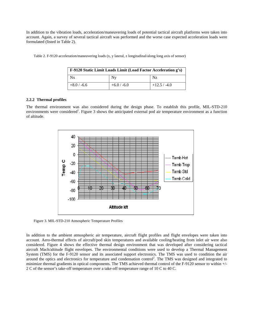
The thermal environment was also considered during the design phase. To establish this profile, MIL-STD-210 environments were considered1. Figure 3 shows the anticipated external pod air temperature environment as a function of altitude.
Figure 3. MIL-STD-210 Atmospheric Temperature Profiles
In addition to the ambient atmospheric air temperature, aircraft flight profiles and flight envelopes were taken into account. Aero-thermal effects of aircraft/pod skin temperatures and available cooling/heating from inlet air were also considered. Figure 4 shows the effective thermal design environment that was developed after considering tactical aircraft Mach/altitude flight envelopes. The environmental conditions were used to develop a Thermal Management System (TMS) for the F-9120 sensor and its associated support electronics. The TMS was used to condition the air around the optics and electronics for temperature and condensation control2. The TMS was designed and integrated to minimize thermal gradients in optical components. The TMS achieved thermal control of the F-9120 sensor to within +/- 2 C of the sensor’s take-off temperature over a take-off temperature range of 10 C to 40 C.

Figure 4. Aircraft Flight Envelope
2.3 Tactical aircraft installation volume
The physical size and weight of the internal carry or external store that could be carried by the potential aircraft also was considered. Constraints such as ground clearance during takeoff and landing, landing gear door clearance, aerodynamic shape and maximum carriage weight were considered and the resulting size and weight of the F-9120 sensor operating volume and its pod system were determined. With additional constraints such as isolator sway space and the gimbal motion required for eliminating the effect of aircraft motion and image jitter due to aircraft vibrations, the maximum size and weight of the F-9120 sensor was then determined. The F-9120 static sensor envelope was constrained to a 19 inch diameter with a 46 inch length with a maximum weight of 350 pounds. Figure 5 illustrates a typical F9120 sensor pod installation with its support electronics. Figure 6 is a photograph of the F-9120 installed in BAE Systems Advanced Aerial Reconnaissance System (AARS) pod which features a rotating window center section for unobscured horizon to horizon cross track field of regard.
Figure 5. The F-9120 can be integrated onto multiple tactical reconnaissance platforms: UAV, commercial aircraft, or supersonic fighter aircraft. (Shown is typical F-9120 sensor pod installation)

Figure 6. F-9120 installed into AARS Pod for carriage on an F-16C/D aircraft. (Note rotating window center section which provides unobscured horizon to horizon cross track field of regard.)
3. MATERIAL BASED TRADES Once the F-9120 sensor design requirements were established, a trade study of mature, flight proven materials was conducted to screen all of the potential candidate materials that could be used for the high altitude optics (mirrors) and the optical support structure. Table 3 lists the materials and material properties that were considered in the trade.
Table 3. Representative properties of mature candidate materials used in F-9120 sensor materials based trade study
Material Property Optical Support Structure Materials Common Support Structure and
Mirror Materials
Optical (Mirror) Materials
BeAl (1) Composite (2) Steel Ti(3) SiC(4) Al(5) Be ULE
Modulus (Msi) 28 25 28 16 48 10 44 9.8
Density (lb/in3) 0.075 0.057 0.29 0.16 0.105 0.098 0.067 0.08
Specific Stiffness (Modulus/Density)
373 439 97 100 457 102 657 123
Thermal Conductivity (W/m °K) 210 52 15.9 6.7 155 180 216 1.3
Specific Heat (J/kg oK) 1506 900 500 580 670 896 1925 767
Thermal Expansion (ppm/°F) 7.7 0.0 9.6 5.0 1.4 13.1 6.3 0.0
Fatigue Strength (ksi) 14 N/A 42 48 N/A 14 38 N/A
Microyield Strength (ksi) 3.0-3.5 N/A 43.5 21.7 N/A 34.8 >4 N/A (1) AlBeMetTM 162, Brush Wellman
(2) Epoxy Resin/Glass Fiber Composite
(3) 6 Al-4 V Ti alloy
(4) Reaction Bonded 30% Si
(5) Aluminum Alloy 6061-T6
3.1 Optical mirror material selection
An all aluminum athermalized system was first considered due to its low risk, low cost and shortest lead time. However, the relatively low specific stiffness of aluminum (less than 1/6 of beryllium) would require much thicker mirrors to meet the strict structural requirements of this system when operating in the high altitude mode. For example, for low cost
reasons, the F-9120 beryllium mirrors utilize a simple, solid, tapered mirror design with an aspect ratio (diameter to thickness) of 13 to maintain imaging performance over the superposition of the structural loads. An aluminum mirror of the same design and stiffness would require an approximate 6x increase in mirror thickness, imposing a large weight and volume penalty resulting in a system weight over 500 lbs (versus 350 lb specification) with a diameter of 21” (versus 19” specification). One compromise would be to decrease the aperture of the long range system by over 20%, reducing the high altitude aperture to 10” or 11” (versus 13.5” specification) but this was deemed unacceptable due to the resulting loss in optical system performance. Another potential compromise would be to utilize an open back light weighted mirror design but this also comes with a large stiffness and fabrication cost penalty. A ULE mirror design was rejected by a similar rationale.
Silicon carbide was also considered for both mirror and structure because of its highest modulus and relatively low coefficient of thermal expansion. However when compared on a weight for weight basis using specific stiffness as the material criteria, beryllium is superior to silicon carbide. It has the highest resistance to deformation under load. This is important for panoramic scanning systems such as the F-9120 not only in terms of optical image quality but for stability of line of sight. Panoramic scan cameras rely upon the scan or roll axis to produce the second dimension of the collected image. Therefore the sensor scan axis performance and the structural rigidity of the sensor determine the amount of jitter present in the imagery.
With regard to the extreme operating temperature range, BAE System’s TMS maintains the sensor temperature range to within +/-2 C of its take-off temperature. This minimizes mirror thermal gradients and allows the use of materials with moderate coefficients of thermal expansion such as beryllium. In addition, referring to table 3, beryllium has the highest thermal conductivity and specific heat of any material listed. Beryllium’s high thermal conductivity allows for thermal equilibrium to be reached rapidly, reducing the potential for distortion due to thermal gradients. Beryllium’s high specific heat means it can absorb significant amounts of heat before distorting.
In terms of total fabrication cost, including parts, assembly and alignment, both silicon carbide and beryllium optics were cost estimated and found to be similar for typical high altitude tactical reconnaissance system production quantities. Although beryllium raw material and processing is typically more expensive than silicon carbide, beryllium mirrors can be designed with integral machined mounting surfaces and features to aid alignment and reduce cost. In contrast, silicon carbide systems typically require bonded inserts with separate machining or lapping operations which increase assembly and alignment time and cost.
To summarize, when sensor imaging performance requirements are held paramount without compromise and the severe structural and thermal profiles of tactical aircraft are considered, beryllium is the mirror material of choice. Beryllium’s unique properties provide superior stiffness to weight and rapid thermal equalization resulting in high quality optical images.
3.2 Optical support structure material selection
Cast aluminum and titanium optical support structures have been used on high performance optical systems produced by BAE Systems in the past. Aluminum has the unique benefit of being able to be cast in a variety of configurations at an affordable cost but lacks the specific stiffness required as discussed previously. In a tactical environment a stiff support structure is needed to ensure a first mode frequency greater than 5x the scan servo bandwidth. This ensures that the effect of the support structure base motion imparted to the optics is kept small so as not to impact image quality. Titanium has the same stiffness problems as aluminum and is extremely costly. For equivalent stiffness, steel was ruled out because of its large weight penalty.
Due to the F-9120 sensor’s relatively large size an all beryllium athermalized sensor was considered prohibitively expensive. Therefore beryllium-aluminum was chosen as the support structure material of choice. Beryllium-aluminum has nearly the specific stiffness as silicon carbide and epoxy composite, but has better thermal equilibration properties and is a relatively close match in coefficient of thermal expansion to beryllium. Like beryllium mirrors, beryllium-aluminum structures can also be designed with integral machined mounting surfaces and alignment features. The combination of beryllium optics and beryllium-aluminum support structure yields the lightest and stiffest sensor system which enables the F-9120 to meet all design objectives: maximum possible structural rigidity with minimum size and weight for good line of sight stabilization, thermally stable and compatible optical support structure and mirrors, a conductive low thermal gradient heat path for thermal management and barrel stability, and adequate stress margins for unlimited service life.

4. F-9120 SENSOR PERFORMANCE 4.1 Laboratory test results
As part of design verification testing, the F-9120 sensor underwent both vibration and thermal imaging tests to verify predicted performance. BAE Systems has in-house capability to measure both the F-9120 sensor and complete AARS pod system over a wide range of structural vibration and thermal environments.
4.1.1 Vibration imaging test
A vibration imaging test was performed on the F-9120 sensor installed in the AARS pod to verify the predicted image quality over the specified vibration profile. The AARS pod was subjected to the worst case enveloped random vibration level indicated in figure 2. As indicated by figure 7, the jitter present in the high altitude visible imagery is minimal due to the high specific stiffness of beryllium and beryllium-aluminum incorporated in the F-9120 design. Nyquist (group 4-2), the highest spatial frequency that the sensor can detect, is still resolved at the detector maximum integration time.
Figure 7. High Altitude Visible Vibration Test Target Image. Nyquist three bar patterns are resolved in both the vertical and
horizontal group 4-2 images. Since each three bar pattern in a group has a different phasing not all patterns can be resolved at once. (Each bar width corresponds to approximately 3.0 micro-radians).
4.1.2 Thermal imaging test
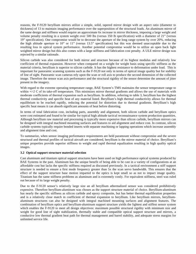
A thermal imaging test was performed on the F-9120 high altitude visible sensor to verify the predicted image quality and focus shift linearity. As part of the optical design process a computer model was developed to predict optical performance over temperature. This model incorporated the effect of CTE differences between the optics and their associated support structures. Because of the small CTE difference between beryllium and beryllium-aluminum the prediction indicated the F-9120 system would not be completely passively athermalized. There remained a small linear focus shift over temperature. This was deemed acceptable as the F-9120 sensor design already incorporated a range focus mechanism for scanning which had sufficient travel to accommodate the focus shift. As can be seen in figure 8, results of the thermal imaging test confirmed the slope and linearity of the predicted focus shift. In addition, Nyquist imagery confirmed that residual optical aberrations were negligible after refocusing as predicted.
F-9120 Sensor Focus vs. Temperature
-0.04
-0.03
-0.02
-0.01
0.00
0.01
0.02
0.03
0.04
0.05
0.06
10 15 20 25 30 35 40
Temperature (Deg. C)
Rel
ativ
e Fo
cus S
hift
(nor
mal
ized
to fo
cus m
echa
nism
trav
el)
MeasuredPredicted
Figure 8. High altitude visible F-9120 thermal focus shift due to CTE difference between beryllium and beryllium-aluminum structure is easily accommodated by range focus mechanism. Measured best-focus positions at Nyquist verified the linear focus curve as predicted by optical design codes.

4.2 Flight test results
During 2006 and 2007 the F-9120 sensor, configured for both dual band high and medium altitude reconnaissance, underwent flight testing on the F-16C/D aircraft. Simultaneous EO/IR imagery was collected by both high and medium altitude cameras to facilitate image exploitation.
Prior to flight, predictions of image quality and coverage versus standoff range were performed for both the high altitude and medium altitude sensors. Image quality was defined in accordance with the NIIRS (National Image Interpretability Rating Scale) scale. The predictions were based upon a mid-latitude winter environment with a 23 kilometer visibility and 30 degree sun elevation. The IR prediction incorporated a target median temperature difference of 1.25 C at 300K. Coverage calculations included the effects of earth curvature.
4.2.1 High altitude sensor range performance
High altitude sensor range performance for 35,000 ft altitude above ground and an air speed of 500 knots is described in figure 9. As an example, for a scan coverage rate of 22,000 NM2/hr the F-9120 sensor can perform a scan from a near point of 23 NM to a far point of 69 NM with a minimum visible image quality of NIIRS 4 at 69 NM. Within the same scan the simultaneous IR imagery maintains a minimum image quality of NIIRS 3 to a range of 55 NM.
High Altitude Sensor Coverage Vs Standoff RangeVNIR & MWIR NIIRS Midpoints
Max Coverage Mode - Altitude 35,000 Feet, Ground Speed 500 knots
0
5000
10000
15000
20000
25000
30000
35000
40000
0 20 40 60 80 1
Standoff range - nm
Cov
erag
e nm̂
2/h
00
VN
IR N
IIRS
6.0
VN
IR N
IIRS
5.0
VN
IR N
IIRS
4. 0
NearPoint
FarPoint
MW
IR N
IIRS 5
.0
MW
IR N
IIRS
4.0
MW
IR N
IIRS 3
.0
Figure 9. High altitude performance for simultaneous Visible/Near Infrared (VNIR) and Mid-Wave IR (MWIR) imaging.
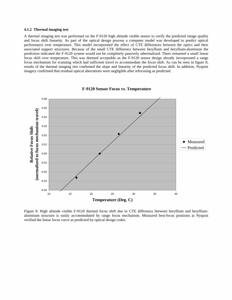
Sample high altitude simultaneous EO/IR imagery from the 2006 flight tests is shown in figures 10 and 11. Although visibility during flight test was less than anticipated due to haze, the flight scenario approximated the assumptions in figure 9. Imagery of Oildale, California was recorded at 34,608 ft above ground at a ground speed of 486 knots. The bottom and top of the images correspond to ranges of 24 NM and 31 NM respectively yielding a coverage rate of approximately 6000 NM2/hr.

Figure 10. High altitude visible image of Oildale, California area. Enlarged images of the storage tanks, refinery stack and
highway correspond to ranges of approximately 26, 27 and 31 NM respectively. The detail present in the enlargements illustrates the high resolution provided by the F-9120 sensor.
Figure 11. Simultaneous high altitude IR image of Oildale, California area. The IR image provides additional information
about the objects in the scene. Note the storage tank levels, hot stack and cold truck cargo.

4.2.2 Medium altitude sensor range performance
Medium altitude sensor range performance for 18,000 ft altitude above ground and an air speed of 400 knots is described in figure 12. As an example, for a scan coverage rate of 3,500 NM2/hr the F-9120 sensor can perform a scan from a near point of 8 NM to a far point of 17 NM with a minimum visible image quality of NIIRS 4 at 17 NM. Within the same scan the simultaneous IR imagery maintains a minimum of NIIRS 3 to a range of 11.5 NM.
Medium Altitude Sensor Coverage vs Standoff RangeVNIR & MWIR, NIIRS Midpoints,
Altitude 18,000 ft - Gnd Speed 400 knots
0
1000
2000
3000
4000
5000
6000
7000
8000
0 5 10 15 20
Standoff Range - nm
Cove
rage
- nm
^2/h
r
Far Point
Near Point
MW
IR N
IIRS
4.0
MW
IR N
IIRS
3.0
MW
IR N
IIRS
5.0
VN
IR N
IIRS
6.0
VN
IR N
IIRS
5.0
VN
IR N
IIRS
4.0
Figure 12. Medium altitude performance for simultaneous Visible/Near Infrared (VNIR) and Mid-Wave IR (MWIR)
imaging.
Sample medium altitude simultaneous EO/IR imagery from the 2007 flight tests is shown in figures 13 and 14. Fortunately, conditions were clear with good visibility and the flight scenario closely matched the assumptions in figure 12. Imagery was recorded at 18,444 ft above ground at a ground speed of 416 knots. The bottom and top of the images correspond to ranges of 5.7 NM and 9.6 NM respectively yielding a coverage rate of approximately 1400 NM2/hr.
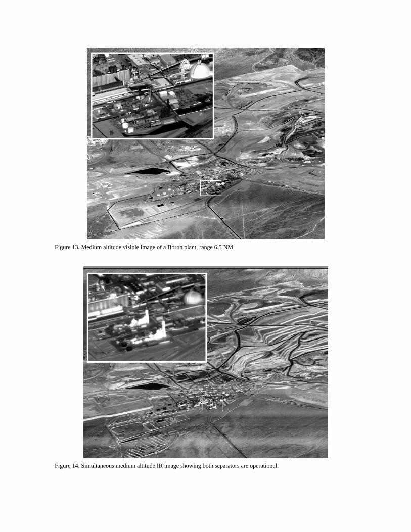
Figure 13. Medium altitude visible image of a Boron plant, range 6.5 NM.
Figure 14. Simultaneous medium altitude IR image showing both separators are operational.

5. SUMMARY The F-9120 sensor was developed to meet the military’s need to gather high quality, long range, simultaneous EO/IR imagery at high altitudes using a variety of tactical platforms. BAE Systems met all key design requirements without compromise through a rigorous and detailed material trade study. The combination of beryllium optics and beryllium-aluminum support structure yields the lightest and stiffest sensor which enables the F-9120 to meet all design objectives. BAE Systems verified the predicted material-related thermal and vibration imaging performance through a number of laboratory tests and successful flight tests on the F-16 aircraft as evidenced by the high resolution simultaneous dual band imagery presented in this paper.
ACKNOWLEDGEMENTS
The authors would like to thank Dipak Banerjee, Bruce Mathews and Ken Baron for their assistance and review of this paper. In addition the authors are grateful to the F-9120 team for their hard work and dedication to the development of this world class sensor system.
REFERENCES
1. “Climatic Information to Determine Design and Test Requirements for Military Systems and Equipment,” MIL-STD-210, January 1987. 2. Engelhardt, M. "Thermal Control of an Airborne Electronics Bay," AIAA Paper No.1217, January 2007. 3. Properties for Aluminum-Beryllium and Beryllium obtained from Brush Wellman. http://www.brushwellman.com/. 4. Properties for Aluminum Alloy 6061-T6 and Titanium 6Al-4V obtained from ASM International-Metals Handbook, Volume 2, “Properties and Selection: Nonferrous Alloys and Special-Purpose Materials”, 1990. 5. Properties for Stainless Steel obtained from ASM International-Metals Handbook, Volume 3, “Properties and Selection: Stainless Steels, Tool Materials and Special Purpose Metals”, 1980. 6. Properties for ULE obtained from Corning website http://www.corning.com/specialtymaterials/materials-products/products_overview/ule.aspx. 7. Properties for Epoxy Resin/Glass Fiber Composite obtained from Volume 1, Engineered Materials Handbook, Composites, page 399, High Strength Medium Temperature Thermoset Matrix Composites, 1987. 8. Properties for Silicon Carbide obtained from Handbook of Optics, Volume 2, “Properties of Selected Mirror Materials”, 1995.