RPT ON GROUND GEOPH SUR BEDIVERE L PLATINUM PROJ
66
43=81 NEWS*l 2.9462 FRANZ 010 REPORT ON GROUND GEOPHYSICAL SURVEYS BEDIVERE LAKE PLATINUM PROJECT NORTHWESTERN ONTARIO for COVENTRY VENTURES INC. VANCOUVER, B.C. RECEIVED O,', \ A W* VMM V*""5 W*** Toronto, Canada September, 1986 J. Roth, M.A. MPH CONSULTING LIMITED
-
Upload
khangminh22 -
Category
Documents
-
view
4 -
download
0
Transcript of RPT ON GROUND GEOPH SUR BEDIVERE L PLATINUM PROJ

43=81 NEWS*l 2.9462 FRANZ 010
REPORT
ON
GROUND GEOPHYSICAL SURVEYS
BEDIVERE LAKE PLATINUM PROJECT
NORTHWESTERN ONTARIO
for
COVENTRY VENTURES INC.
VANCOUVER, B.C.
RECEIVEDO,', \ A W*
VMM V*""5 W***
Toronto, Canada
September, 1986
J. Roth, M.A.
MPH CONSULTING LIMITED

SUMMARY
A ground geophysical program consisting of magnetometer and horizontal
loop EM surveys was successfully completed by MPH Consulting Limited dur
ing the period July l to 24, 1986 at the request of Coventry Ventures
Inc. of Vancouver, B.C. over portions of the latter's 34 claim property
in the Atikokan area of northwestern Ontario.
Located within the west-central portion of the Quetico metavolcanic/met
greenstone belt, this property is inferred from prior exploration, moder
ate outcrop and geophysical information to be predominantly underlain by
northeast-trending metasediments intruded by lenticular ultramafics rang
ing in composition from pyroxenite to peridotite. This geological sett
ing is favourable for polymetallic Cu-Ni-Pt-Pd sulphide deposits as evi
denced by the better explored deposit at Lac Des Iles to the east and,
most particularly, by the two known occurrences on the present property.
Previous exploration, principally carried out in 1929 and 1957, consisted
of shallow trenching, limited ground geophysical surveys and several
drill campaigns, directed mainly at Cu-Ni sulphide targets. The previous
drill holes tested several geologic targets, intersecting serpentinized
ultramafics containing sulphidic zones. Anomalous platinum values up to
a 0.07 oz/t Pt and 0.07 oz/t Pd over 5 ft plus low Cu and Ni values are
reported in drilling conducted by Nashua Exploration and Mining Ltd. in
the western part of the property.
The geophysical program consisted of detailed magnetometer and horizontal
loop EM surveys undertaken on two grids (west and east) totalling 19 km
to detect conductive ^ magnetic features that might constitute favourable
targets for platinum and/or polymetallic sulphide mineralization, and,
more generally, to provide an augmented understanding of the geology,
structure and economic potential of the property.

- li -
The magnetometer survey outlined with good confidence a complexly zoned
and disrupted lenticular ultramafic on the West Grid, whose location and
character conforms closely to that inferred from previous information.
On the East Grid, the magnetic survey revealed a series of disconnected
moderate anomalies thought to reflect narrow ultramafic intrusions; this
portrayal differs from the continuous character previously projected.
The MaxMin HLEM survey detected and partly delineated two possible bed
rock conductors located within or close to the ultramafics on the West
Grid. These could reflect poorly conductive sulphide zones of limited
strike length and hence are considered plausible targets for further ex
ploration. No credible conductor was detected on the East Grid that can
be correlated with the probable ultramafic rocks.
The property also retains a potential Pt-Pd mineralization associated
with non-conductive disseminated sulphides.
In view of the discerned potential of the property, further exploration
is recommended consisting of:
l . Geochemical sampling and geologic prospecting to define the possible
mineralization and its environment, and to correlate in detail pre
vious drilling and trenches with the present survey grid and results .
2. Reconnaissance TP/reslstivity surveys on selected grid lines to
search for sulphidized horizons or zones within the ultramafic host, as well as to confirm the probable extent of the ultramafics.
3. Contingent on the preceding results and based on an integrated eva
luation of all data, an initial diamond drill program, tentatively
estimated to consist of 10 short holes totalling 1,500 meters, to
evaluate those targets identified as having favourable geophysical
and/or geochemical characteristics.

42FeiNE0eei 2.9462 FRANZ 010G
TABLE OF CONTENTS
Page
SUMMARY
l .0 INTRODUCTION l
2.0 LOCATION, ACCESS AND INFRASTRUCTURE 3
3.0 PROPERTY 4
4.0 GEOLOGY
4.1 Regional Geology 6
4 .2 Property Geology 6
4.3 Mineral Deposits and Exploration Models 8
5.0 PREVIOUS WORK 13
6.0 SURVEY PROCEDURES
6 .1 Magnetometer Survey 15
6 .2 Horizontal Loop EM Survey 16
7.0 DATA ACQUISITION 17
8 .0 DATA PROCESSING AND PRESENTATION 19
9.0 INTERPRETATION
9.1 Magnetic Survey 21
9.2 MaxMin Results 24
9.3 Discussion 27
10.0 CONCLUSIONS AND RECOMMENDATIONS 29
Certificate
References
APPENDIX A: Geophysical Equipment Specifications

LIST OF FIGURES
Figure l: Location Map 2
Figure 2: Property Map 5
Figure 3: Regional Geology and Mineral Occurrences 12
LIST OF MAPS
West Grid (W)
Map W-l: Contoured Total Field Magnetics 1:1,000
Map W-2: MaxMin HLEM Profiles: 5=100 m, f 777 Hz 1:1,000
Map W-3: MaxMin HLEM Profiles: 3=100 m, f=3555 Hz 1:1,000
East-Grid (E)
Map E-l: Contoured Total Field Magnetics 1:1,000
Map E-2: MaxMin HLEM Profiles: 5=100 ra, f^777 Hz 1:1,000
Map E-3: MaxMin HLEM Profiles: 5=100 m, f=3555 Hz 1:1,000

l .0 INTRODUCTION
This report presents and discusses the results of a ground geophysical
program carried out by MPH Consulting Limited of Toronto at the request
of Coventry Ventures Inc. of Vancouver, B.C., over portions of the
latter's property near Atikokan in northwestern Ontario.
The geophysical programs, consisting of magnetometer and HLEM surveys,
was undertaken to detect and define conductive zones that could reflect
economic gold or polymetallic sulphide mineralization, to define associa
ted magnetic features and more generally to better understand the geology
and structure of the property.
The report includes a description of the various exploration techniques,
an appraisal of the individual results as well as an integrated evalua
tion, followed by recommendations for further exploration of the precious
metal potential of the property.

PROPERTY) LOCATION
U.S.A.
REGIONAL LOCATION MAP
SCALEOO Q^^^^^ZOO
KILOMETRES
DETAILED LOCATION MAP
COVENTRY VENTURES INC.BEDIVERE LAKE PROJECT
LOCATION MAPto, C-888
di i.li l M* Flgur*1
y J. RothMPH
Pat*. September, 1986
MPH Consulting Limited

- 3 -
2 .0 LOCATION, ACCESS AND INFRASTRUCTURE
The Bedivere Lake property is situated within the Atikokan-Shebandowan
sector of the Thunder Bay Mining District of northwestern Ontario (Figure
1).
The claim group is located approximately 120 km west-northwest of Thunder
Bay, Ontario. It is centered approximately at longitude 90" 54' 30",
latitude 48" 46' 30" onN.T.S. sheet 52-B-15.
Access to the property is facilitated by a logging road (Great Lakes
Paper Ltd.) which passes within 500 m of the western property boundary.
This road departs north from Highway 11 at a point approximately 30 km
west of Kashabowie. A series of lakes provides boat access to the east
ern portion of the claim group from the above logging road.
The terrain is greatly undulating. Overburden appears to be relatively
shallow in both upland and swamp covered areas with the ultramafics form
ing intermittently exposed ridges. Forest cover consists of red pine,
spruce, balsam fir, birch and poplar, with local areas of dense under
brush. A large part of the western end of the property has been recently
logged, leaving behind a heavy cover of deadfall, brush piles and dense
new underbrush.
The property is well located with respect to infrastructure in that a CNR
railway line and an electric power transmission lines pass six km south
of the property.

- 4 -
3 .0 PROPERTY
The property consists of thirty-four (34) contiguous unpatented mining
claims. These are shown on M.N.R. Land Titles Map G-511, Bedivere Lake
(Thunder Lake Mining Div.), a portion of which is reproduced as Figure 2.
The individual claims are numbered as follows:
*TB 840809 TB 857413
*TB 840810 *TB 857414
*TB 840811 *TB 865866
*TB 840812 *TB 865867
*TB 840813 *TB 865868
TB 840814 *TB 865869
*TB 840815 *TB 865870
*TB 840816 TB 865871
*TB 840817 TB 865872
TB 840467 TB 865873
TB 840468 TB 865874
TB 840469 TB 865875
*TB 840470 TB 865876
*TB 840471 *TB 865877
TB 840472 *TB 865878
TB 857411 TB 865879
TB 857412 TB 865886
Those claims accompanied by an asterisk are subject of the present sur
veys and report.
Claims TB 840809 through 840817 staked by Seymour Sears of Wana, Ontario
in August, 1985. The remaining claims were staked by Kennedy L.J. Byers
and Robert Ekstrura of Toronto, Ontario in January, 198,6. The claims have
been subsequently transferred to Coventry Ventures Inc.

•^
SCALE: 1 \nc\\ = '\/2 Mile
COVENTRY VENTURES INC.BEDIVERE LAKE PROJECT
PROPERTY MAPHe, C- BBS J. Roth
MPHFigure 2 Seplamber, 1986
MPH Consulting Limited

- 6 -
4 .0 GEOLOGY
4.1 Regional Geology
The Bedivere Lake claims are located within the Precambrian metavol-
canic-metasedimentary belt in northwestern Ontario. As seen in Map
2022 (Western Lac des Mille Lacs Area) at a scale of l inch to l
mile (Irvine, 1963), a portion of which is reproduced as Figure 3,
the general geology of the Bedivere Lake area can be simply describ
ed as a narrow east-west trending band of metavolcanic rocks border
ed by a granitic batholith on the north and in fault contact with a
complex turbidite-metasedimentary sequence to the south. The fault
is characterized by a band of chlorite schist. It is thought that
the metavolcanic rocks underlie the metasediments.
The metavolcanics and metasediments have been locally cut by numer
ous ultramafic intrusions in the form of irregular dykes and small
stocks. These have been subdivided petrologically into peridotite,
hornblendite and feldspathic hornblendite.
The above rocks display a variable foliation oriented east-west to
northeast with a vertical to north dipping attitude.
Small stocks and dykes of quartz monzonite and dykes of diabase have
been observed cutting all of the above rocks.
4.2 Property Geology
The following brief descriptions of the geology underlying the Bedi
vere Lake property are adapted from upon a summary presented in the
report by Sears (1986) based on data obtained from O.G.S. assessment
files, a report on the geological mapping of the Western Lac Des
Mille Lacs Area (Irvine, 1963), and a brief geological, reconnaissan
ce in early September 1985.

- 7 -
The property is underlain by a sequence of metasedimentary rocks in
truded by separate bodies of ultramafic composition. The metasedi
mentary rocks are classed as paragneiss and are composed of quartz 4-
plagioclase + biotite + garnet + staurolite. They are strongly
foliated with foliation planes striking 070 0 and dipping 80 0 -85 0 to
wards the north, although local variations caused by the proximity
to intrusive rocks and structural features are common. Quartz
lenses, stringers and gash fillings as well as dykes of aplite occur
locally.
The larger western ultramafic intrusive consists of hornblendite and
feldspathic hornblendite with a central core of pyroxenite and horn
blende peridotite. The smaller, elongated eastern intrusion is made
up of hornblendite and feldspathic hornblendite. The ultramafic
rocks vary from fine to coarse grained and locally display intense
alteration (sericite-carbonate-biotite-chlorite-talc-sperpentine-
magnetite) and sulphide minerals, the latter consisting mainly of
pyrrhotite (both magnetic and non-magnetic varietites) and lesser
chalcopyrite. Pentlandite and platinum group minerals are also
associated with the sulphide-rich zones although neither were obser
ved in hand specimen.
The western ultramafic intrusive is crudely lenticular in its sur
face exposure, at least 1,300 m in length and displaying a maximum
width of 300 m.
As seen in Geophysical Map 1113G, Bedivere Lake, the regional aero
magnetic data are characterized by a bland background, which pro
bably reflects the dominantly metasedimentary lithologies. Isolat
ed, moderate anomalies punctuate the background.

- 8 -
The eliptical magnetic high near the centre of the map reflects the
western ultramafic intrusion. Indications from magnetic data sug
gest a south to southwest plunging attitude.
The eastern ultramafic intrusive has a relatively narrow, irregular
dyke-like shape. As presently defined, it extends at least 480 m in
length and with a width up to 30 m. It appears to be near vertical
in cross-section.
The eastern ultramafic has no discernible aeromagnetic response at
the elevation and flight line spacing of the BSC survey, athough
some magnetic character is suggested in a more detailed ground sur
vey reproduced In Irvine's (1963) report.
Character sampling of several old trenches carried out by Sears con
firmed the presence of anomalous Pd and Pt accompanied by low values
in Cu and Ni in sulphide material in both the western and eastern
intrusive. Detailed correlation of past exploration with the pre
sent grid remains uncertain.
4 .3 Mineral Deposits and Exploration Models
The greenstone belts of northwestern Ontario harbour a rich endow
ment of precious and base metal deposits. These include classical
volcanogenic polymetallic massive sulphide deposits hosted by dif-i
ferentiated volcanic (Uchi Lake, Mattabi) or by gneissic sediments
of tuffaceous? origin (Geco); syngenetic/stzructural gold-sulphide
deposits associated with tuffs in a mixed volcanic/sedimentary en
vironment (Heralo) or with chemical sediments (Geraldton); Cu-Ni+Pt-
Pd deposits associated with gabbroic intrusions (Thiery) or with
serpentizied ultramafics (Lac des Iles).

- 9 -
In particular, the Quetico belt is considered to be favourable for
most of the above deposit types and is noteable for the presence of
Cu-Ni-Pt-Pd mineralization. The Lac des Iles Pd-Pt deposit is
located in the southern Wabigoon subprovince, immediately north of
the western continuation of the Quetico belt. Two interesting Pt-Pd
sulphide occurrences are found on the present property, and other
Cu-Ni prospects associated with mafic or ultramafic rocks are re
ported .
In addition, previous exploration has identified gold occurrences in
mixed volcanic/metasedimentary terrains, notably In the Shebandowan
area.
Economic interest in the Lac des Iles area began in the late 1950's.
Extensive exploration of the Lac des Iles gabbroic complex was un
dertaken by a variety of mining companies during the period from
1958 to the present. The work by Texas Gulf Canada Ltd. and Boston
Bay Mines Ltd. in 1976 revealed a deposit of 20.4 MT averaging 0.72
gm Pt and 5 .03 gm Pd per tonne in the Roby zone. Since the recent
sharp escalation in prices for the platinum group metals the deposit
is receiving renewed exploration by Madeleine Mines .
As summarized by Sutcliffe (1986), the deposit lies In the Lac des
Iles Complex, the largest of over 20 mafic to ultramafic plutons in
an east-northeast trending linear zone which extends over 200 km
from Atikokan, Ontario to Lake Nipigon. This zone approximately
parallels the boundary between the Quetico and Wabigoon Subprovin- ces, two major subdivisions of the Superior Province. Most of these
plutons are small plugs and dykes. Larger Intrusions such as the
Lac des Iles Complex have an upright conical shape.
The intrusions are late tectonic, emplaced Into granitoid host rocks
and many have well-preserved primary igneous mineralogy. The litho-
logies range in composition from ultramafic peridotite and-pyroxen
ite cumulates to magnesian gabbronorite and iron-rich gabbro.

- 10 -
Marginal zones rich in hornblendite occur around the perimeter of
some intrusions and are interpreted to be due to contamination of
mafic magma by a granitic component.
In the Lac des Iles Complex, the Roby Zone mineralization occurs
along the contact of a primitive gabbronorite phase and an evolved
iron- and volatile-rich gabbro phase. The PGM are associated with
disseminated and net-textured copper-nickel sulphides. Vysotskite,
(Pd, Ni) S, is the most abundant platinum group mineral. The PGM
are also associated with sulphide-bearing pegmatitic gabbro and
gabbro breccias developed at this contact.
Anomalous PGM concentrations have also been reported from several
other ultramafics and from the Tib Lake intrusion northwest of Lac
des Iles. In addition, significant PGM concentrations occur in the
small intrusions in the vicinity of Atikokan which suggests that the
entire zone of intrusions has important potential as a PGM metallo
genic province .
Mineralization in the Lac des Iles area is quite different from the
stratiform mineralization of large, well-layered Igneous intrusions
such as the Bushveld and Stillwater complexes. In this area, the
intrusions are small and although some layering is present, a well-
developed igneous cumulate stratigraphy Is absent. On both a re
gional and local scale, however, the intrusions exhibit features
similar to the zoned Alaskan ultramafic complexes. Key geological
features associated with potential PGM mineralization in this area
include:
1. an association with disseminated and net-textured sulphides;
2. identification of mixing zones of primitive and evolved magmas;
and
3. development of pegmatitic gabbroic rocks and breccias.

- 11 -
Thus from a geophysical perspective, detailed magnetic surveys are
anticipated to be beneficial in delineating host ultramafic charac
teristics as well as possibly identifying sulphide zones, while EM
surveys should detect zones of more concentrated, conductive sul
phides. IP surveys may prove useful in searching for zones of dis
seminated sulphides.

W55'
-\U—— -U—— - -- a" - - V•* l -i v J ." FlTQTPTf~"TV f1 *:l^TR~CTte
Q O
If!"liQ. O 0-1
fi
iflilll
ISs s
l
5 ' SS: o
l l
l lK ut'
CobiCu C *B Q. o
™-o S--0.-0 SO i; O OI--Uc I? t-^s.ir
lIII!!
•o a OD
D
S ?s*j
,;.*-.;
'
g fiw S-""riliO S H 5
s*-II^3S li
A tTrN (n
O 52 H> aZ C f
** ? ^ x* 29 *
a|gS^ ? 5 C- 0 *
n a;3 i.™
^ p-!
•D 30 mO
TT ™ ^
— ET ?
0PIH
CZO 0z3aZ
-arm
g, 3
18I mS 2jfe"
Sa•5
t
om
ln
m O mzD
O
t
[fro
*9
2.
H^^ r
cis
S s
8m
rn
mO)
00 O>r m
3H- l—1
m
ls-
S1
5 sio c 3aSsw" Q.
5-5?
Ill 111
l s-l !s- -:

- 13 -
5.0 PREVIOUS WORK
The property and its immediate environs have been subjected to intermit
tent exploration over the past 60 years. The following recital is based
on a compilation of previous work assembled by Seymour Sears from assess
ment research.
Two occurrences of copper, nickel and platinum group elements were dis
covered through prospecting by James W. Lawrence in 1928. The Spence
Development Company Limited was formed in 1929 and a number of shallow
trenches were excavated. Five drill holes were reportedly completed on
the most easterly occurrence and four holes on the west occurrence.
Exact drill hole locations, logs and assay data are not available.
In 1957, the next date of reported exploration activity in this area,
Nashua Exploration and Mining Limited completed twelve drill holes on the
east occurrence in a program intended to locate an economic deposit of
copper an nickel. Nine of these holes intersected a favourable ultra
mafic intrusive body, outlining a strike length in excess of 500 m.
Sulphides were encountered in each of the nine holes mentioned above, but
the only available assays are from hole 3, the first hole to intersect
the ultramafic intrusive (pg., 1957). An average of 0.02 oz/ton Pt, 0.02
oz/ton Pd, Q.23% Ni and Q.53% Cu over 239 ft (between 234 and 473 ft) is
reported in O.G.S. Assessment Files. Individual five ft assays up to
0.07 oz/ton Pt, 0.07 oz/ton Pd, Q.31% Ni and 0.80% Cu are recorded. It
should be noted that hole 3 was oriented obliquely to the northwest trend
of the ultramafic body of the above intersections probably represent an
exaggerated true thicknesses. At the time of Page's report another hole
had been drilled from the same setup and similar rocks and mineralization
were encountered. Only rough drill logs and hole locations were-record
ed, although T .N. Irvine presents graphic drill sections in a government
geological report (Irvine, 1963).

- 14 -
Also in 1957, five drill holes were completed on the western occurrence
by Montco Copper Corp. Ltd. Three of these holes intersected sulphide-
bearing ultramafic rocks. No assays were reported, and hole locations
are shown relative only to the then existing claim posts. No log of the
fifth hole in this series is available. Graphic logs of four of these
holes and their assumed locations are shown in Geological Report No. 12
(Irvine, 1963). In this report, DDH no. 3 is shown as having been drill
ed at -30", in conflict with the drill log information (-90 0 ).
The next reported work on the property was in 1966-1967 when Midland
Nickel Corporation Ltd. completed a sixteen drill hole program, with
thirteen of these holes in the area of the eastern occurrence. Only two
of these encountered the ultramafic intrusive, the remaining being
collared too far to the south and east. The target for these holes is
somewhat obsure. The remaining three holes, which tested the north-cen
tral part of the western intrusive, intersected significant thicknesses
of sulphide-bearing ultramafic rock. No assays were reported.
The most recent exploration activity recorded in the claim area was that
of Asarco Exploration Company of Canada, Limited in 1974. Work included
a geological survey, a ground magnetometer survey, and a VLF-EM survey of
the western intrusive and reconnaissance EM profiles across the eastern
intrusive. Results did not indicate the presence of a "major conductive
zone", so no further work was recommended at that time.

- 15 -
6.0 SURVEY PROCEDURES
6.1 Magnetometer Survey
Magnetometer surveys represent a long-established geophysical tech
nique providing useful information pertinent to the detection and
delineation of magnetic lithologic units and mineralization.
A variety of instrumentation has been developed over the years to
match the varied objectives and environments in which magnetic sur
veys are undertaken; these include airborne, ground and drill-hole
applications.
For mineral exploration, ground surveys are typically carried out
with proton precession magnetometers measuring variations in the
total intensity of the earth's magnetic field. Such variations can
be interpreted to determine the probable configuration of the causa
tive magnetic source and its magnetic susceptibility.
Magnetic surveys in Precambrian metavolcanic terrains for precious
and base metal deposits generally provide information as to magnetic
sources that may be associated with conductive EM targets and help
characterize distinctive lithological units and structural disrup
tions .
The use of digitially recording field and base station magnetometers
serves to ensure high quality, drift-free compiled data, which is
usually displayed in contoured form.

r- 16 -
6 .2 Horizontal Loop EM Survey
The horizontal loop electromagnetic method constitutes a much-prac
ticed technique for detection of conductive mineralization and lith-
ologles .
The basis of the technique consists of measurement of the changes in
EM coupling between two horizontal coils maintained at a fixed se
paration and specified frequency. These departures in the in-phase
and quadrature components are typically recorded as a percent vari
ation from a nulled setting.
Current instrumentation, exemplified by the Apex MaxMin series of
HLEM instruments, enables accurate measurement of such variations at
5 or more frequencies.
The HLEM technique is generally susceptible to throrough quantita
tive analysis in terras of conductor geometry and conductivity. This
analysis enables identification of the characteristics of tabular
bedrock conductors arising from sulphide or graphite sources. Such
sources can generally be distinguished from conductive overburden.
However, weakly conductive bedrock sources (such as faults and shear
zones) can yield responses substantially similar to narrow troughs
of conductive overburden. IP/resistivity surveys provide a means of
resolving such ambiguities.
Data is normally presented as stacked profiles for the in-phase and
quadrature values with a separate plot for each frequency.

- 17 -
7.0 DATA ACQUISITION
Prior to commencing the geophysical surveys, detailed cut-line grids were
established over two portions of the property. For the West Grid, initi
ally an baseline oriented N65"E was established with crosslines turned
off from 7+OOW to 6+OOE at 50 meter intervals. The cross lines, which
extend 200 to 300 m northwest and southeast of the baseline, respectively
were chained and picketed at 25 meter intervals for a total of 16 km of
grid.
For the East Grid, the baseline was oriented N40 0 E and crosslines turned
off at 50 m intervals. The grid extends from line 3+50W to 3+OOE and
from 2+OON to 2+OOS, for a total of 6.5 km.
The survey grids and topographic information together with the claim
locations were then compiled to constitute base maps at a scale of
1:1,000. For convenience, the data are presented separately for each
grid.
The geophysical program consisted of magnetometer and HLEM surveys carri
ed out over each entire grid.
The magnetic survey was executed with an EDA PPM 350 total field magneto
meter which digitally records total field values to ^ l nT. Stations
were recorded at 10 meter intervals to ensure appropriate detail for
shallow, narrow sources. An EDA PPM 400 base station magnetometer locat
ed at the crew base (Crestview Motel) was utilized in conjunction with
the field magnetometer to record and enable correction for the diurnal
variations. A total of 19 km of magnetic survey was completed.
The HLEM survey was carried out with an Apex Parametrics MaxMin II in
strument measuring the in-phase and quadrature components of the second
ary electromagnetic field at 1777 and 3555 Hz at a station interval of 25

- 18 -
meters and a coil separation of 100 m. A total of 19 km of MaxMin survey
was completed.
Complete instrument specifications are presented In Appendix A.
Data acquisition was carried out over the period July l to July 24,
1986 by a MPH geophysical crew under the direction of Doug Croft, B.Se.,
geophysicist assisted by John Foster, B.Se., geologist, and Willis
Keeshig, Technician
Logistics were co-ordinated In the field by Derek Hall, senior geophysi
cal technician. The geophysical program was designed and implemented by
the author, under the overall direction of Dave Jones, P.Geoph. and
Vice-Presldent, MPH.

- 19 -
8.0 DATA PROCESSING AND PRESENTATION
The raw magnetometer data have been corrected for diurnal variations by
subtracting the value recorded simultaneously at the base station from
the traverse value. The corrected values were then plotted in the field
in the form of strip charts and subjected to preliminary assessement in
the field as well as to identify any possible problems.
After checking and editing, the corrected total field magnetic values
have been plotted in final plan form on the base maps at a scale of
1:1,000 and appropriately contoured as seen in Maps W-l and E-l for the
West and East Grids, respectively. Superimposed on the contoured magne
tic features are the interpreted magnetic sources and structural aspects.
The sources, which are dominantly narrow and linear, are distinguished as
to low, moderate or high susceptibility. Where feasible, areas with dif
fering magnetic characteristics are distinguished as different domains.
The in-phase and quadrature HLEM readings were converted into digital
files in the field and plotted in profile form in preliminary fashion
using a portable micro-computer.
The edited in-phase and quadrature HLEM readings have been computer plot
ted in annotated profile form at a profile scale of l cm z 10% and a
horizontal scale of 1:1,000, comprising Maps W-2 and W-3, and Maps E-2
and E-3 for the West and East Grids, respectively, as shown in the table
below. (Note that the profiles have a resolution of Q.5% while the an
notated readings have been rounded off to the nearest percent.) Conduc
tive features are identified on each of these plans and characterized as
to the quality of the discerned anomaly, with the more important zones
given an alhabetic designatioh. Where feasible selected anomalies are
quantitatively analyzed in terms of a thin conductive sheet.

- 20 -
TABLE l
Geophysical Maps
West Grid East Grid
Magnetics
MaxMin: 100 m
1777 Hz
3555 Hz
W-1
W-2
W-3
E-1
E-2
E-3

r--
- 21 -
9.0 INTERPRETATION
9 .1 Magnetic Results
On the West Grid the magnetic survey disclosed a complex pattern
of strong to very strong magnetic anomalies extending across the
central part and enclosed north and south by a much more subdued
magnetic terrain.
On the basis of the character, pattern and amplitude of magnetic
anomalies two magnetic domains have been distinguished.
The central domain has a much higher average magnetization and is
characterized by strong to very strong local linear and elongated
anomalies. This domain clearly demarcates the ultramafic complex
and its component lithologies.
Individual anomalies over the ultramafic typically attain 3,000 to
4,000 nT relief (and in one case in excess of 10,000 nT) implying
susceptibilities of 5,000-10,000 micro-cgs units equating to a rock
locally containing 2-57, magnetite.
Individual linear anomalies can be traced across the survey grid for
several hundred metres and generally display a grid north-south
trend .
There are also podiform magnetic anomalies of 50 to 100 m areal ex
tent. Their different character could indicate a different original
petrologic composition or simply a different metamorphic or altera
tion history.
As is well, known the process of serpentinization tends to increase
the amount of magnetite in the ultramafic rock. The above anomalies
and susceptibilities are entirely consist with such serpentinized
ultramafics.
- 22 -
No overall pattern can be discerned in the magnetic anomalies within
the interpreted serpentinite that might reflect a petrologic change
from pyroxenitic to peridotitic composition.
The present survey has reasonably defined the extent of the inter
preted serpentine, although to the (grid) west the magnetic body has
not been fully delineated.
A series of crossfaults have been interpreted disrupting the serpen
tinite with modest offset. These faults have orientations varying
from (grid) north-south to northwest.
In addition, changes in character across the serpentinite from south
to north suggest the presence of several strike faults within the
serpentine. Additional strike faults may exist although these can
not be recognized on the basis of magnetic data.
The location of these faults, both cross and strike faults, may be
of significance vis-a-vis loci favourable to the emplacement of sul
phide mineralization.
Alternatively, the process of sulphidization may have locally de
pressed the magnetic susceptibility so that local magnetic lows
could be regarded as favourable for sulphide mineralization. In
this respect it is noted that block contained between lines 1+OOW
and 2+50W has a significantly lower average magnetization than the
surrounding portions of the ultramafic.
Domain II, which constitute the remainder of the survey grid north
and south of the interpreted serpentinite, is characterized by sub
dued magnetic relief although anomalies of several 100 nT can be
found locally.

r- 23 -
This subdued character and pattern of modest local anomalies is en
tirely consistent with gneissic sediments possibly accompanied by
minor volcanics.
Finally it is worth contrasting the portrayal on the ground with
that registered in the aeromagnetic surveys commented on earlier.
At the scale of the ground surveys the overall character of the body
has been divided up into a series of very local anomalies whereas
the aeroraagnetics reflected the Integrated magnetic response of the
body as a whole.
Consequently whereas the aeromagnetics may give some indication of a
possible south dip of the overall body, no such information can be
directly obtained from the present ground magnetic survey. Slightly
lower background values to the north as compared to the south of the
body suggests that a south or near-vertical dip would not be incon
sistent .
On the East Grid the magnetic pattern is rather dissimilar from
that observed on the West Grid.
The contoured magnetic results principally display a series of
moderate to moderately strong local anomalies of discontinuous and
erratic character. There is no sense of a substantial coherent body
of magnetic ultramafic rocks.
The most Intense and persistent anomalies are to be observed span
ning lines 0+50E to 2+OOE. The anomalies are narrow with magnetic
relief on the order of 500-1,000 nT consistent with susceptibilities
equivalent to Q.25-1.0% magnetite content.

- 24 -
The pattern of magnetic anomalies disclosed suggests a discontinuous
ultramafic feature of narrow width and probably lacking in the
petrological complexity of that of the ultramafic on the Western
Grid. The disruptions in the more intense magnetic features may re
flect crossfaulting as is tentatively interpreted in Map E-l.
Additionally there are a series of even more modest discontinuous
anomalies observed both north and south of the above-descibed anoma
lies. These are considered to reflect gneissic host rocks, although
there is in fact no clear distinction to be made between those
sources that are probably caused by serpentinized ultramafics and
those related simply to variations within the gneissic metasedi
ments .
9.2 MaxMin Results
On the West Grid, as seen in Maps W-2 and W-3, the MaxMin survey
disclosed a series of weak, predominantly quadrature anomalies which
are considered to have some geologic validity. Inphase variations,
superimposed on a slightly elevated background, are considered to
reflect slight coil misalignment due to local topographic changes,
since the inphase behaviour is essentially unchanged as a function
of frequency, contrary to that normally expected for valid geologic
conductors.
Although the predominantly quadrature features are indeed weak in
amplitude, of limited extent and of uncertain character, they are
viewed as of potential interest in the context of exploring for
small, weakly conductive sulphide accumulations that might be anti
cipated for PGM deposits in this environment. Normally such weak
features would be largely ignored or treated as possible to probable
overburden responses.

- 25 -
The two principally anomalous zones, designated A. and B, are found
in the east-central portion of the West Grid.
Anomaly A is recognizable on both the 1777 and 3555 Hz quadrature
data as extending from line 2+50E near 0+65N to 3+50E near 0+15S.
The anomaly is best defined on lines 2+50E and 3+50W where it consi
dered a possible bedrock feature.
Because of the very modest amplitude and very low inphase-to-quadra-
ture ratio; one cannot readily derive from calculated thin sheet
models accurate estimate for conductivity-thickness and depth;
however a conductivity-thickness of less than one mho and the depth
of less than 30 m are clearly suggested.
Anomaly A trends (grid) northwest-southeast somewhat oblique to the
indicated local magnetic trends. The eastern extent of the anomaly
coincides approximately with a crossfault interpreted from the
magnetics.
Anomaly B is partially indicated by weak responses at or beyond the
ends of lines 1+50E and 2+OOE near 1+75N.
In part because of its imperfect definition and in part because of
poor character, the anomaly is considered as a probable overburden
response, although a weak bedrock response cannot be entirely rated
out.
Anomaly B lies along the interpreted northern boundary of the
ultramafic and hence could reflect a bedrock feature along the
contact or, more likely, a thicker accumulation of overburden at the
edge of the ultramafic.

- 26 -
Three additional very modest quadrature responses are observed on
line 1+OOW near 1+OON, on lines 4+50E and 5+OON near 1+OON, and on
line 6+OOE near 0+75N.
Of these the response on line 4+50E just beyond the northern limit
of survey coverage is the most likely to reflect a bedrock source.
Since the anomaly characteristics are only*inperfectly glimpsed, no
firm determination of anomaly character can be made.
The very weak response on line 1+OOW coincides with a trace of an
crossfault inferred from the magnetic data.
Thus on the West Grid the MaxMin survey was unsuccessful in detect
ing any substantial definite conductor that might reflect a large
accumulation of conductive sulphides. However the weaker responses
could reflect shorter more poorly conductive sulphide horizons or
accumulations.
On the East Grid the MaxMin survey detected a series of weak
responses in the southwestern portion of the grid.
As seen in Maps E-2 and E-3, these responses are evident as weak,
predominantly quadrature anomalies on lines 2+OOW through 3+50W in
the vicinity of 1+50S. The responses spanning lines 2+OOW through
3+OOW may in fact reflect a single continuous weak conductor trend
ing (grid) northwest. The character of this response is such as to
suggest overburden as the probable cause.
Additional weak one line responses were detected on lines 1+OOE and
3+50W but these are not viewed as of immediate exploration signifi
cance .

- 27 -
Comparison with the magnetic data indicates that the more continuous
MaxMin feature in the southwest corner is considerably distant from
any inferred ultramafic body. Thus if it is indeed a weak but valid
bedrock conductor it is unlikely to be of significance in the con
text of exploration for PGM deposits.
Finally, there is a pattern to be discerned in the inphase varia
tions which trace out an approximate (grid) west-northwest trend
across the central part of the survey grid. No equivalent or corre
lating quadrature responses accompany the inphase variations. The
MaxMin trend corresponds to the principal magnetic trend on this
grid. Hence the EM response, which is not that expected for a typi
cal conductive feature, may be reflecting a resistive but permeable
body such as a strongly magnetic serpentinite.
9.3 Discussion
The magnetic survey successfully attained the objectives of signi
ficantly augumenting geologic understanding of the extent and chara
cter of the ultramafics and their host environment. Correlation of
individual anomalies and/or structures with the results of detailed
geological mapping and geochemical prospecting may enable recogni
tion of specific anomalies as of direct exploration interest.
The MaxMin HLEM survey results did not disclose any strong definite
bedrock conductor that could be related to a conductive sulphide
zone within or at the margins of the interpreted ultramafics.
However, sulphide zones of interests in terms of platinum mineral
ization may have a restricted strike length and may display very
weak to nil conductivity. Hence the weak possibly bedrock features
detected by the surveys are of interest and merit scrutiny as part
of a ground prospecting and mapping program.

- 28 -
For the above reason IP surveys will form a valuable and recommended
complement to the preceeding geophysical surveys as a means of de
tecting and delineating zones of disseminated sulphides that might
carry appreciable PGM values .
The preceeding geophysical results and discussion merit renewed
scrutiny once a detailed geologic map of the area has been prepared
and the planned geochemical sampling program has been carried out.

- 29 -
10.0 CONCLUSIONS AND RECOMMENDATIONS
The magnetometer and MaxMin HLEM surveys carried out on the Bedivere Lake
platinum project have provided substantial information pertinent to the
evaluation of the property in that:
On the West Grid:
* The detailed magnetometer survey has outlined the serpentinized
ultramafic generally conformable with its previously projected
extent. Internally the magnetic ultramafic was found to consist of
a number of strong linear anomalies with an average trend of N60 0 E
(grid east-west) accompanied by several larger, podiform magnetic
units. Crosscutting and strike faults were identified which may
indicate loci favourable for sulphide mineralization.
* The MaxMin HLEM survey yielded two weak but possible bedrock con
ductors within or close to the boundary of the serpentinized ultra
mafic constituting targets meriting attention in further explora
tion programs.
On the East Grid:
* The detailed magnetometer survey disclosed a series of discontinu
ous narrow magnetic features Interpreted as reflecting thin ultra-
mafics Intrusives, rather different in form and character from the
ultramafic on the West Grid and also different from that projected
on the basis of previous information. Crossfaultlng is suspected
for the dislocations in the magnetic features.

r- 30 -
* The MaxMin survey failed to disclose any credible conductor that
could be reasonably associated with the magnetic portions of the
ultramafic, although several very weak anomalies were detected in
other sectors of the grid.
On the basis of the preceding results and conclusions, it is recommended
that further evaluation of the Pt-Pd potential of the Bedivere Lake pro
perty be undertaken to consist of:
l . Geologic mapping and geochemical sampling over and around the in
ferred ultramafic bodies in an attempt to identify the presence of
mineralization and/or anomalous PGM values. This work should include
a diligent effort to relocate as many old drill hole collars and
trenches as possible so as to tie the present results and grids more
closely into the previous work.
2. An IP/resistivity survey should be run on lines selected to cover en
couraging MaxMin responses and/or geologically or geochemically in
dicated zones or areas within the ultramafic.
3. The present geophysical results together with the results of the pre
ceding additional phases should be integrated to yield priority tar
gets for subsequent testing by diamond drilling. Although difficult
to estimate at this time, such an initial diamond drilling program
might be reasonably be anticipated to consist of five to ten short
holes totalling 1,000-1,500 m.
Respectfully submitted,
'J. Roth, M.A.

REFERENCES
Grant, F.S. and West, G.F., 1965, Interpretation Theory in Applied Geo
physics .
Honsberger, J.C., 1966, Report on the Claims of Midland Nickel Corpora
tion Ltd. near Owakonze Station, Thunder Bay Mining Division Ont
ario .
Hood, P.J. (ed), 1979, Geophysics and Geochemistry in the Search for
Metallic Ores, GSC Econ. Geol. Report, No. 31.
Irvine, T.N., 1963, Geological Report No. 12, Ontario Department of Mines
- "Western Lac des Mille Lacs Area". Includes Map No. 2022; scale
l" " l mile.
Irvine, T.N., 1960, Preliminary Geological Map No. P 88, Lac des Mille
Lacs Area, West Half; scale l" = | mile.
Morley, L.W. (ed), 1968, Mining and Ground Water Geophysics, GSC Econ.
Geol. Report, No. 26.
Naldrett, A.J., 1981, Platinum Group Element Deposits, CIM Special volume
23, chapter 10, pg. 197-229.
Nicholls, E .B., 1974, Geophysical Report on Knappet Claims, Bedivere Lake
Area, Thunder Bay Mining District, Ontario, for Asarco Exploration
Company of Canada, Ltd.
Ontario Geological Survey, Assessment File. Miscellaneous data on file
at the Thunder Bay Mining Division office, pertaining to the
Bedivere Lake Area.

CERTIFICATE
I, Jeremy Roth of Toronto, Ontario hereby certify that:
1. I hold a Bachelor of Arts degree in Mathematics from Harvard College,
Cambridge, Mass., and a Master of Arts degree in Geophysics from
Harvard University, Cambridge, Mass.
2. I have practised my profession in exploration geophysics continuously
since graduation.
3. I have based conclusions contained in this report on my personal
experience in geophysical exploration methods and knowledge of geo
physical interpretation techniques.
4. I hold no interest, directly or indirectly, in this property other
than professional fees, nor do I expect to receive any interest in
the property or in Coventry Ventures Inc. or any of its subsidiary
companies.
Toronto, Ontario OeremyOctober, 1986 MPH CONSULTING LIMITED

- 2 -
Page, T.W., 1957, A report on the Owakonze Property of Nashua Exploration
Si Mining Limited, Port Arthur Mining Division, Ontario.
Sutcliffe, R.H., 1986, The Northern Miner Magazine, v. 5, p. 57.
Sears, S., 1986, Report on the Bedivere Lake Platinum Prospect, Thunder
Bay Mining Division, for Coventry Ventures Inc.
Wyllie, P.J. (editor), 1967, Ultramafic and Related Rocks, John Wiley and
Sons Inc.

APPENDIX A
Geophysical Equipment Specifications

MAXIVIIIM IIEM
m Five frequencies: SSS, 444, BBS, 1777 and 3555 Hz.m Maximum coupled C horizontal-loop ) operation with
reference cable .
H Minimum coupled operation with reference cable. H Vertical-loop operation without reference cable.m Coil separations: SB, 50,100,150, SOO and 25O m
C with cable 3 or 100,500,300,400,600 and BOO ft.m Reliable data from depths of up to IBOm CBOOft).m Built-in voice communication circuitry with cable.
m Tilt meters to control coil orientation.

SPECIFICATIONS :
Frequencies : 222, 444, BBS, 1777 and 3555Hz. Repeatability;
Modes of Operation: MAX: Transmitter coil plane and re ceiver coil plane horizontal (Max-coupled; Horizontal-loop model. Used with refer, cable .
M l N: Transmitter coil plane horizon tal and receiver coil plane ver tical (Min-coupled mode). Used with reference cable.
V. L. : Transmitter coil plane verti cal and receiver coil plane hori zontal (Vertical-loop model. Used without reference cable , in parallel lines.
25.5O.1OO.15O.2CO S25Om (MMH) or 1OO, 2OO, 3OO, 4OO.6OOand BOO ft. (MMHF). Coil separations in V.L.mode not re stricted to fixed values.
- In-Phase and Quadrature compo nents of the secondary field i n MAX and M IN modes.
- Tilt-angle of the total field in V.L. mode .
- Automatic, direct readout on SO mm (3.5") edgewise meters in fvlAX and MIN modes. No null ing or compensation necessary .
- Tilt angle and null in 9O mm edge wise meters in V.L.mode.
(— Coil Separations :
Parameters Read:
Readouts :
Scale Ranges : In-Phase: ±POV.,±1OOV. by push button switch .
Quadrature: ±2D 7,., ±1OO '/. by push button switch .
Tilt: i 75 "A slope .Null (V.L.I: Sensitivity adjustable
tay separation switch.
R e nclii b i li t y :
±O.25"Xo Col'1% normally, depending on conditions, frequencies and coil separation used .
Transmitter Output: . 222Hz :22OAtm2- 444Hz : 2OO Atm2- BBS Hz : 12OAtma- 1777 Hz : BDAtm2- 3555 Hz : 30Atms
Receiver Batteries: gv trans, radio type batteries (4). Life: approx. 35hrs. continuous du ty (alkaline , 0.5 Ah ). less in cold weather.
Transmitter Batteries : 12V 6 Ah Gel-type rechargeable
battery. (Charger supplied!.
• In-Phase arid to O S V. ;
Quadrature Til!; : 1V..
O.25 V.
Reference Cable : Light weight 2-conductor teflon cable for minimum friction. Unshield ed. All reference cables optional at extra cost. Please specify.
Voice Link: Built-in intercom system for voice communication between re ceiver and transmitter operators in MAX and MIN modes, via re ference cable .
Indicator Lights : Built-in signal and reference warn ing lights to indicate erroneous readings .
Temperature Range; -4O"C to+BQ-C C - 4O"F to*14O"F).
Receiver Weight: 6kg (13lbs.)
Transmitter Weight: 13kg ( 23 Ibs. 1
Shipping Weight l Typically BOkg C135lb3.), depend ing on quantities of reference cable anci batteries included. Shipped in two field/shipping cases.
Spe L, i f . r ci t., r . - :-. nuDject; to c:n^^c) ; ..
APEX P/XRAMETRICS LIMJTEOSOO STEELCASE RD. E., MARKHAM. ONT, CANADA. .L3H
Phone: (416) 495-1B12 Cables: APEXPARA TORONTO Telex :OB-SBB773 NORDViK TOR

Total Field Magnetometer••l :: : :. ; : : l : ,*^;: : .::i : |- :;;:: i;::: i:: •t.--:i:-:-
:- l :! l . i -- ; ' ::i.".-: •:.:..;-|. ::l::-.!:
The PPM-350 is the latest addition to EDA's OMNIMAG*™ series of magnetometers and gradiometers. It is engineered to provide users with the latest state-of-the-art advances in microprocessor technology, including many features that are unique in the field.
Major benefits and features Include:* Significant increase in productivity* Lowered survey costs* Automatic diurnal correction* Programmable grid coordinates* Highly reproduceable data* Ergonomic design* Simplified fieldwork* Computer-compatible

Description Functions Features and BenefitsThe EDA OMNIMAG PPM-350 is a high-technology, proton precession total field magnetometer that measures and records the earth's magnetic field at the simple touch of a key. It identifies and records the location, time of each measurement, computes the statistical error, and records the decay and strength of the signal
1 being measured.The PPM-350 is a microprocessor-
. based system and employs a ' memory magnetometer conceptpioneered by EDA.
. Packaged in a compact, lightweight, rugged housing, the PPM-350 in corporates ergonomic-design features that provide maximum
" comfort and ease-of-operation in the field. It is used in a chest- mounted mode with a shoulder-
- harness. It has a large Liquid Crystal Display for easy reading, even in direct sunlight, and its oversized
. touch-sensitive keyboard permits cold-weather operation without having to remove gloves.
In a typical field survey operation, the PPM-350 can perform all of the following functions:* A visual readout and storage of
the following information in an absolutely secure memory that prevents data loss or tampering:- total magnetic field
magnitude- time of measurement- grid coordinates for every
reading- statistical error of total field
reading- signal strength and decay
measurement* Users have a choice of three
input, or data storage, modes:- manual record- spot record- automatic update record
* Users also have a choice of three output modes:- to a DCU-200 magnetic
cassette recorder- to a DCU-040 or DCU-400
thermal printer- to any RS-232C-compatible
microcomputer* Each reading is automatically
assigned a record number which can also be used to identify loca tions of measurements taken off the grid. This also serves to recall data, as well, simply by key ing in the record number.
- Sub-grid coordinates and posi tion up-date are given, permit ting more detailed study within the main grid, without altering main grid data.
- Many readings can be taken at one point to verify a reading, without updating the position.
Productivity Up, costs DownUsers of the OMNIMAC PPM-350 can enjoy in creases in survey produc tivity by as much as 50 07o because of the solid-state
: ;. features that are designed ' into it. This increase in pro ductivity, with resultant lower survey costs, is made possible because it enables the operator to take measurements faster and with greater accuracy
thanTonventional techniques permit. This, in turn, allows the survey operator to spend more time in the field surveying significantly more area than would be otherwise possible.Automatic Diurnal correctionDiurnal variations are corrected automatically and in just a few minutes, instead of the two or three hours required in manual operation. The raw total field data collected and stored in the PPM-350 is corrected by the PPM-400 Base Station Magnetometer through a single cable link. Using the linear interpolation method, corrected data is produced faster and moreaccurately, because the possibility of human error is reduced.Programmable Grid coordinatesMeasurements are also made faster and more accurately because the location of each reading is taken automatically on an incremental basis, and recorded along with the time of that measurement. An additional benefit of this feature is that it can provide the basis for computer plotting to obtain survey profiles.Highly Reproduceable DataThe PPM-350 provides users with the highest confidence level in the

idustry. Its highly reproduceable•v-ata is a result of four leading- edge design features that Iminate the need for taking . uiltiple readings:• An exclusive Signal Processing• Technique*
Constant Energy Polarization that maintains equal energy to
r- the sensor even when the main battery supply decreases
•- Sensitivity to ±0.02 gamma that ensures repeatability of readings Automatic Fine-Tuning that takes
, the previous reading as the base for the next
""rgonomic Design...perator comfort and efficiency were prime considerations in '"he design of the new PPM-350. It
lightweight and is encased in a 'rugged housing that permits ^Deration in a wide variety of field ; :nditions. The oversize keyboard tnables the operator to take measurements without removing roves. Large LCD's make reading .. .nuch easier, even in bright sunlight.
eldwork Simplified•j.nce each reading is automatically stored in a non-volatile memory, He need to make handwritten ( Dtebook entries on total field magnitude, time of reading, line f*id station numbers, etc. is
iminated. This reduces the need tor notebook usage by the pperator, thereby improving pro- 1 jctivity. Also, it allows field t,drveys to be made under all weather conditions.
Dmputer Compatiblewl EDA OMNIMAG systems can in terface with any computer using 1-232C standard. This enables L aeration of profiles, contour maps, etc.
Other Features* Data Recall. Daily readings can
be recalled either by record number or in sequence.
* Non-Volatile Memory. A lithium battery with a life-expectancy of 4 years provides total protection of data stored in memory and of the real-time clock in case the primary battery runs down or is removed.
* Environmental Dependability. PPM-350 operates in temperature extremes of -35 0 C to 55 0 C. At-25 0 C, a heater automatically activates to ensure LCD perfor mance. Environmental sealing allows operation in very high humidity and in driving rain.
* Higher Gradient Tolerance. More accurate readings are obtained because the PPM-350's optimized sensor geometry and reduced size result in higher tolerances to local gradients.
* Power Supply Versatility. Users can choose from a variety of power packages:- rechargeable sealed lead acid
battery belt or cartridge - disposable alkaline "C" cell
battery belt or cartridge. Error Analysis. This unique feature is a great time saver because the calculation of the statistical error of each reading lets the operator make an on- the-spot decision whether that reading should be stored or not. Memory upgrade. The stan dard memory of 1383 readings is optionally expandable up to 2555 readings.Decimal Spacing, intermediate readings can be stored every 12.5 units, while using the usual 25-unit station interval. Internal Real-Time Clock. More accurate and reliable measure ments can be made and stored because time is taken to the nearest second. Also, the operator need not wear a wrist- watch, which is a common and often overlooked source of magnetic interference.

SpecificationsDynamic Range Sensitivity
- Statistical Error Resolution Standard Memory Capacity Absolute Accuracy
Display Resolution j Capture Range
h Display
LLL L L L
Gradient Tolerance Sensor
Sensor Cable
Operating Environmental Range
Power Supply
Battery Cartridge Life
Weight and Dimensions Instrument Console only Lead Acid Battery Cartridge Sensor
^ System Complement
18,000 to 93,000 gammas ±0.02 gamma 0.01 gamma1383 data blocks or readings ±15 ppm at 23 0 C, 50 ppm over the operating temperature range 0.1 gamma± 250/0 relative to ambient field strength of last stored value Custom-designed, ruggedized liquid crystal display with an operating temperature range from -35 0 C to 4-55 0 C5,000 gammas per meter Optimized miniature design. Magnetic cleanliness is consistent with the specified absolute accuracy Remains flexible in temperature range; includes low strain connector -35 0 C to + 55 0 C; Q-100% relative humidity; weather-proof Non-magnetic rechargeable sealed lead acid battery cartridge or belt; or, Disposable "C" cell battery car tridge or belt2,000 to 5,000 readings, depending upon ambient temperature and rate of readings
3.4 kg, 238 x 150 x 250 mm 1.9 kg1.2 kg, 56 mrn diameter x 200 mm Electronics console; sensor with 3-meter cable; sensor staff; power supply; harness assembly; operation manual.
EDA is a pioneer in the development of advanced geophysical systems and has created many innovations that increase field productivity and lower survey costs.
EDA's OMNIMAG series consists of the PPM-350 Total Field Magne tometer, PPM-400 Base Station Magnetometer, and the PPM-500 Vertical Gradiometer. Contact us now for details.
EDA Instruments Inc. l Thorncliffe Park Drive Toronto, Ontario Cannda M4H 1C9 Telex 06 23222 EDA TOR Cable instruments Toronto UI16I 125-7800
In US.Af: D A Instruments Inc.5151 Ward RoadWheat Ridge ColoradoU.SA. 80033Telex 00 450681 DVR(5031422-9-112

PPM SERIESPbrtable Magnetometers
General DescriptionThe portable PPM Series magnetom eters consist of four standard field units which have a number of com mon features and specifications. They represent the most advanced application of microprocessor technology, sophisticated software and system design available to date.
Standard features of all units include:J Improved accuracy....: Enhanced data reliability and
validity..VI Automatic fine tuning.11 Programmable 24 hour clock.i.."! 5000nT per metre gradient toler
ance.U Unique interchangeable sensor
design.L] Only two simple controls, a key
pad and mode switch.Li Custom-designed low temperature
LCD which displays field reading, error, time, signal quality and decay rate, battery status and descriptors. Elimination of all cables by attach ing sensor to console. Patent pending signal processing technique.Statistical error analysis of signal. Keypad with audio feedback. Switch selectable test mode to verify subsystem status and system performance.
D Internal lithium battery back-up system to protect status tables, programmes and data.
n Constant energy polarization.D Convenient snap-in power car
tridges containing any disposable "C" cells or rechargeable sealed lead acid batteries.
J Operating temperature - 300 C to -f500 C.
J Rugged custom designed alu minum investment cast case offer ing complete protection against rain and dust.
J Lightweight construction. Weighs as little as 4.0kg.
PPM-200 Total Field MagnetometerAs the basic unit in the series, the PPM-200 measures the earth's magnetic field to sensitivities of 0.1nT and displays the resulting data on the high visibility LCD. This unit has automatic power-off capability to prevent the unneces sary consumption of power. The standard sensor attached to the main electronics console leaves the operator with complete freedom from cables and the incessant problems they create. This unit can be upgraded at a later date to higher capability levels by adding additional electronics, memory and software subroutines.
PPM-300 Total Field MagnetometerThis model is the most advanced field magnetometer in the world. In addition to providing the total field magnitude and time, it also records on its internal solid state memory, the grid co-ordinates (line and station) and reading error. The non-volatile memory can store up to 700 data blocks, therefore eliminating any need to record data manually. Accumulated data is regularly transferred into either of two Data Collection Units, the DCU-100 Thermal Printer or the DCU-200 Magnetic Cassette Re corder. The use of the latter unit permits the complete computer handling of data which includes background and diurnal correc tions, automatic plotting and rou tine geophysical interpretation.
PPM-400 Base Station MagnetometerThis integral sensor and console package is the first magnetometer specifically designed for base station applications, which include airborne and ground survey cor rections. It's unique configuration allows it to be set up above the ground and away from hazards and local magnetic interferences. Unlike other base station magnetometers which have a limited number of switch selected sample periods and limited versatility, the PPM-400 is completely programmable through its keypad. This includes operator selection of either relative (differ ential) or absolute measurements. As in the PPM-300, all data is stored internally in a high capacity non-volatile memory which is trans ferred periodically into either the DCU-100or DCU-200. Also unique to this instrument is a "snooze" alarm to conserve power. In simple terms, the microprocessor acts as an alarm clock and turns power- draining circuits off following each reading and automatically powers up just prior to taking a subsequent reading.

fc Ministry of Northern Affairs
nesOntario
Report of Work(Geophysical, Geological, Geochomical and Expenditures) 42FBINE8M1 3.9462 FRANZ
Mining Actm in-- c xpi'iii i Lj.iv- i-i
— Do noi usf shoili-cl .irras h.-low.
900
Type of Surveyltl
_..Geophysicalr Claim Hoiiinrit)
Kennedy L.J. ByersAiM'.'V.
55..ChiUen.Road.i..Toronto,.Ontario M4J 3C7Survey Company
rtsultinfe '-imited__.
Townihip or Area ^A f*\
l Bedivere Lake (NTS 52-B-151 .!Pf ospt'cior'^ Lironrc No
l A45656
at* of Survey ((rom 81 to) iTotai Miloi of lini01 07 861 2007 86 (6.0km) 3.3lV l Mo. l Yr. j Day | Mo. | Yr. |_ ______
OatO
Day
ne Cut8 mi
Name-end Addre** o1 Author lo* Geo-Technical report)
J. Roth, MPH Consulting Limited, 2406-120 Adelaide Street West, Toronto, OntarioCiuilits Rutiufsiutl pci Eacli Claim in Columns atSpecial Provision*
For first survey:Enter 40 days. (This includes line ciiMnu])
Fm tsich .iiMilmnnl *uivry tiviiitl lltr s;mie gull:
E ut ci 20 days dor each)
Man Days
Complete reverse side .mil i-nti'T loi.il(s) hen*
A irhornc Credits
Note: Special provision; credits do not apply lo Aiibomi- Su'vuys.
- Electromagnetic
- Oll*or
Geological
Geochemical
Geophysical
- Electromagnetic
rt/l^gnotometer
Geological
Gftochomical ,
Electrorrtagnetic
MiiynutOMtuiiu
Day* per Claim
20
Oayi per Claim
.....
Oavt per Ci.iim
bx)M-inluun:s1 vi*** O* WQI k Porlormnd
Porlornicrl on O a i ml 4}
Calculation O' Expcncliunu Oays C'Otiits
Total Expcndiltiret
S -^ 15Instf \irt iOM^
Tot*tl Oays CrediU mo y bu jppornoficii Ji th choice. Enter number of day* credits pn da in columns nt righi.
. . . ——
Total Days Credits
s
c claim holOtr's m telccTed
DM o
Aug 13. 1986Recorded
Certification Verifying Report of W
gnature)
Mining Claims Traversed (List in numerical sequence)Mining Ctairn
Pr.l,,
TBNumber
857414865866
865867 865869
865870865877
865878
- - - --
i - L * -
- - -:-
- - —— -
Expend. Dayt Cr./r60j 6Qf
L
6\
6((
V
10
- —
. ———
ArJ
7
Mining ClaimPrest i K I Number
,.....
THlMl
^
j;9;io
- -.
IN DER BAYJIM'S DIVISION
. , m?* T -.., , l * \ \Vj |vs ;" '" ! ':ai,6 1 S iocs
LI;].? l|T13l4
ixptncl. Oayi Cr.
— —
.. .. ———
^ ...
PMW
Total number of mining claims covered by this report o* work.
l l :rrby certify that l have a personal ami intimate knowledge of the tacts set forth m the Report of Work annexed hereto, havinn, performed the work or witnessed same during and/or after iti completion and the annexed report is true.
Name and Pottal Addrex of Person Certifying
J. Roth, MPH Cosnulting Limited, 2406^120 Adelaide Street West. Tnrnnny- 4ni- fl r-tn~~ ' "' " '- ~ r- - ~ *— - 'CertiL/dAf ISlfrdlure)

Ontario
Ministry ol Northern Affairs aw"*-' nes
Report of Work(Geophysical, Geological, Geochcmic.il and Expenditures)
Mining Act
^^^^^~ •••W^^P"* r l
Instructions: — Please la^^ or epr ml. . .-— —- H number of mining claims traversed fJ
exceeds space on this form, attach a lisi. ~" l Note: — Onlv tl.iys crerMs calculated m the
"Exrwinhliiti"." M-rlioi' m;iv lippnteind m Ihi- "E*pi*ni! D.iys Ci " Columns.
— Do noi usr shniliMl nrrns holow.
Type of Survey(t)
_ GeophysicalClnim HoulctUI
Robert Ekstrom
Townihip or Area
Bedivere Lake (NTSOipi'dOf X Lt
A41078! No.
Total Miiet of line Cutl Rolph Road , Toronto, Ontario M4G 3M3
Survey Company |Date o* Survey (Irom 8. to)01 07 86| 20 07 86 n ^ . ,, n, . Moh Consuitim: Limited ,. ...___....___l o.v l MO. i vr. \ p7v i MO. i vr. i U.63 mi (1.0km)
Name and Addrni o* Auihoi lof Geo-Teehnical report)
J. Roth, MPH Consulting Limited, 2406-120 Adelaide Street West, Toronto. OntarioCiutJits \v:i Eiich Claim in Columns 31 nijtU
ipocijtl PrOvitiOni
For drst survey: Enter 40 days (This,nrlu.1o,l,M,;o,n,m,)
Foi r.u-li .iilililinn.il Miivi-y tisinii lin 1 •it'MTin qi ut.
Enter 20 days dor each)
Max Days
Complete reverse side .md iMittu tot. ills) here
Airborne C'Adit*
Note: Special provisions rrprlits do not apply to Aiiboiitc Suivuys.
Geophysical CUm.
- Eleclromagnetic 1 j f*
M,,,,,.,0.,,.,n,
n.-..l,o...ai..c
Geological
Geochemical
Geophysical
20
. -
Days par Claim
- Elr-ctromagne'ic j
MaQnotometor
- Oihcf
Geological
Goochomical
Electromagnetic
M,ic]noloinulm
Rn*1innirMiic
Da vi per Clftirn
Mining Claims Traversed (List in numerical segui-nce)
hx|h'inliliiirs lus powuiTypnni Wo* l- I'm loinunl
Portormcfl on Cla-mUt
Cnlculatior- of Expenrtiiure Da y t Credits
Total Expenditures
S -i- 15
Total Days Credits
s
Imir urtmn* Total DJVS Cieoni rnav Ou upportionci: ul the claim hotder't choice. Enter nurnbfti of day* credit? prr claim (elected in columns .11 right.
Mining ClaimPralix | Number
TB 840470840471
t
-.
Day* Cr.
g
\
; :~. L
--—
Aj
Mining CtairnPrefix 1 Number
t
t - * rv i- t,
V-' v. -,- i i
THM
*-
8i9|10
JNDER BAIN'N'J DIVISION
JG 1 1S wll'l? 312:3(4,
Expend.Days Cr.
- ——
PU5\y
Total number of mining claims covered by this
i of work.
Date
Au e 13. 1986Recorded Ufa
Certification Venf/ing Report of Work
nature)
l hereby certify that l hdve a person.il and innmate knowledge of the facts set forth m the Report of Work annexed hrauo. h.ivmq pcriormed the nark or witnessed same during and/or alter its completion and the annexed repo t is true.
Name and Poitnl Adrirvtt of Pvrson Certifying
J. Roth, MPH Consulting Limited, 2406j-j.20 Adelaide Street West. Toron-- --- - -- - -- iet. West. Ton'/ri \ c—

MiniSlryol Report Of WorkNorthern Allairs
-,es (Geophysical. Geological.Ontano Geochomical and Expenditures)
^fjgffj^j^' InMrue/onV- PleasNtfTpe 01 p*rmi. '•^^iJ^ . , *1 y -If number of mining claims traversed *^|- ^/JLl(/? k*^ exccuds sp.icc on ihis form, attach a list. l
(T Mining Act
— If number of mining claims traversed exccuds sp.icc on this form, attach a list.
Note: — Only d.iys crerl.ls calculated in the "Expriuliiunv." M'c-tnin rrw, lip rntcrpcl .11 Hi- "Evprmf D.iys Ci." columns.
— Do noi USP th.iiliMl nrr.is linlow.
Typi
Cln. r
A.I.I
Surv
l of Surveyls) *
GEOPHYSICALn Hol.lorlt)
Seymour Sears•••••.
P.O. Box 2058 Wey Company
MPH CosnultineName and Address of Author (of
J. Roth, MPH Co
awa,
LimitGeo Tec
naultCiutJits RuqiiustL'tl pu i E;icli Claim inSpecial Provisions
For first survey:
Enior 40 days (This includes line cultini))
Ftii iMt:h .iilditinnnl Mnvry: iisiiur (he vMTtn fit id:
Entei 20 days (for each)
Man Days
Complete reverse side .mil iMiii-r lot. il (s) here
Airborne Credit*
Note: Special provisions credits do nnt apply to Airborne Surveys.
Ontario
ed
Date of Survey (f01 07 8Day l Mo. | Y
Township or
Bedivt
rom aV to)61 20 Cr. j Day M
sre Lake (NTS 52-B
D 184^5
JToiai Miles of' line C
I7 i v?6| (6.8km) 4.2
-l*L
5 mil iihmcal report)
ing Limited, 2406-120 Adelaide Street West, Toronto. OntarioCulumns al fiylit Mining Claims Traversed (List in numerical sequence)
Geophys.eat i^* p*r
- Electromagnetic t ^
M.I OH '*' Otlli'IOr ; — -.
R.iitmiitnii ic '
Otluu .
Geological
Geochemical
Geophysical Claim
- EloriromAgnetic
Mjgnoiometer
Geoiog
...omn.MC
h.,
cai
GcochAn-iic.il
Electro
Days per Cl.iim
magnetic
M.ignutoinutitr
R,.1,oi,10...C
hxiM'iiililiiii". (cxclii(li;s |)owi:i Mi i|M""'.|)1 ypp nl VVor^ P0rlormi*il
Poilormerl OD Ommli)
Cile til. 11 ion ol Expenditure Du y* Credits
Toral Expenditures
l-Total
Di y J Credits
15 =
Tout Day* Credits m j y bo upportiOrtci! Ji the claim holder's choice. Enter number ol days credits prr clAim selected in column* At right.
Dnio Recorded H
Aug 13, 1986 (Cer
Mining ClaimPrefix
TB
.'•i, .-.f.': -.
Number
840809
840810
840811 840812
840813 A
/t1
\ '
,
-. . .. . -
;; [
L.
x pen d. lays Cr.
ArJ
IptfWAi
*-
-
,
...-
.. ——
m ^
p *'
Mining ClaimPrefix 1 Number
: D
^\
? '^
t t
r
Expend. Days Cr.
— ——
l
. . -
Total numher of mining claims covered by this . report of work. J
l For Office Use Only K ___________ —^
rt^^3'ty'Xyt/^j* l S.gnat ure )/kPr~ i
[Total Days Cr.lDau Recorded |M'2ZLTIr*rB*r 3fc Vv
iLA^Le^yS
lineation Verifying Report of IpTbrk "^^^*^^^~" l
1 hereby certify thai 1 hjve a person.i or witnessed same during and/or after
Narne and Postal Address of Person Cert
J. Roth, Mrt Consult!y-j^~(-rL-M*~)
and innmaie knowledge of the (acts set forth m the Report of Work annexed hvrnto, havmq perlorn.ed the work its completion and the annexed report is true.lying
ng Ltd .4, 2406-120 Adelaide Street West. Torotrf. Ontario A.r~t*^ r^Tjyr*" ^(^^Js^^yyA1 T^^^^l ' /K

Ministry of Northern Affairs
es
Report of Work(Geophysical, Geological, Geochemical and Expenditures)
Bet
Ontario
Type of Surveytil
_ .JSeophysicalClairn Holilorm
Seymour Sears
— , P.O.Box 2058 Wawa, OntarioSurvey Company
MPH Consulting Limited
.
J-Mining Act
a: - rleasi ^^— If number of mining claims
exceeds sp.icc on this form, Note: — Oniy d.ivs credits calculi
"Expciuliiuiiv." SPI-I ion may In" pntorpc m lin- "E.xpi'inl. D.IVS Ci " columns
— Do not use sKoili'd arms below
.lbu .*" f
Townthip or Area
Bedivere Lake (NTS 52-B-15)
D18445
J Date of Survey (from oV to) Total Mi lw of line Cut ~01 07 861 20 07 86 33 ml fs 3klB -vDay l Mo. l Yr. l Day | MO. | Yr. l J* J ml U.JKm;
Name end Address of Author (of Geo-Technical report)
J. Roth, MPH Consulting Limited, 2406-120 Adelaide Street West, Toronto, OntarioCiL'iJits Rci|ucsl(jO pui Each Claim in Columns at rujhtSpecial Proviiiont
For first survey:
Enter 40 days. (This include* line cuinmi)
Foi tMcli ftilitiliniinl surwry: 'HSU li) Ilw \.1MMI C|IUl: l
Enter 20 (Jays Uor each! ;
1 Days per Claim
Electromagnetic AS\
Man Days
Complete reverse side .mil piiit'r lol.ills) herp
O thor
Geological
Geochemical
Geophysical
Mjfjnotomeior
Other
Geological
Goochomicnl
Ai'norne Credits
Note: Special provisions Etectrorrvagnetic credits rio not apply lo AnbOMH- Surveys.
RiirlioniiHf ic
Day* perClaim
Day* per Ct.iim
|)owci Mi ippmi|llyprolVVoik Por 1 (v rr*i*fl
'ortormerl oil Oaimti)
OilcuLinon ol EMpencliture Oavf Crerdls
Total EicnonrtitiireiTotal
Oav* Credit!
Instf ucliomTotal Djys CrnOiti nuy uu apportioned Jt the claim holdar't choice. Enter nurnbor of davicfocliti prr claim talectad in columm nt right.
Certification Verifying Report of Work
Mining Claims Traversed (List in numerical sequence)Mining Claim
Prefix
TB
~ -. .
,"--
Number
840815
840816
840817
- - —
i ^ "'i r ^ -
i
Expend. Dayi Cr.
jtf
V-.. ——
" '. *..f
l:: . \. '
Mimng ClaimProf ix Number
-
r-
u' v
AM"t ~~'
--
- — - -
" MIN"'*"-- OIVISK
AllO A C 1^ AUR " ^ v
Exoend. Day* Cr.
.... ——
- - ———
\
lAYM
Total numher of miningclaims covered by thijreport of work.
1 hereby certify that 1 have a personol and mlimate knowledge of the (acts set forth m the Report of Work annexed hi'nno, havinq performed the work or witnessed same during and/or after its completion and the annexed report is true.
Nam* and Pottal Addrets of Penon Certifying
J. Roth, MPH Consulting Limited, 2406-120 Adelaide Street West, Tor/Jhto. Onta

Ontario
Ministry of Natural Resources
GEOPHYSICAL - GEOLOGICAL - GEOCHEMICAL TECHNICAL DATA STATEMENT
File.
TO BE ATTACHED AS AN APPENDIX TO TECHNICAL REPORTFACTS SHOWN HERE NEED NOT BE REPEATED IN REPORT
TECHNICAL REPORT MUST CONTAIN INTERPRETATION, CONCLUSIONS ETC.
2 gCdCODgb b O
Geophysical
Bedivere LakeType of Survey (s) _____ Township or Area _____ Claim Hnlrler(s) Coventry Ventures Inc.
Vancouver , B.C.
MPH Consulting Limited
J. RothSurvey Company___ Author of Report __ Address of A,,rhnr 2406-120 Adelaide Street West. Toronto
Covering Dates of Survey July l - July 24, 1986-——-——(linecutting to office)
22 kmTotal Miles of Line Cut.
SPECIAL PROVISIONS CREDITS REQUESTED
ENTER 40 days (includes line cutting) for first survey.ENTER 20 days for each additional survey using same grid.
DAYS per claimGeophysical
—F.Wtrnmagnprir 40
20
-Other-Geological.
AIRBORNE CREDITS (Special provision credits do not apply to airborne surveys)
Magnetometer____Electromagnetic ————— Radiometric
DATE:. Oof l**
.Electromagnet!(eni
SIGNATURE:.7 Author of Report or Agent
Res. Geol. .Qualifications a*~ gf- ' lPrevious Surveys
File No. Type Date Claim Holder
.Q.Q.L.1.!.^..........sem*
MINING CLAIMS TRAVERSED List numerically
TB 840470(prefix) S
840471 ^
840809
840810"?-
840811
840812
840813
840815 x/
840816
840817
857414
,8.65866 a
865867
865868^
865869
865870
865877
865878
TOTAL CLAIMS.
(number)
i
i
18
837 (5/79)

GEOPHYSICAL TECHNICAL DATA
GROUND SURVEYS — If more than one survey, specify data for each type of survey
MagneticsNumber of Stations ^ 797Station interval 10 m
Profile *™le N/A
rontnnr interval 10 nT
HLEM ^88 IMiimher of ReaHinps
25 m Tine sparing 50 m
1 cm = 5%N/A
Tnstrnment EDA PPM 350
INDUCED POLARIZATION
oiS
z;S1yEd
o
>-> lVfcL
ff
Accuracy — Scale constant .Diurnal r^rrTti*™ method
Base Station check-in interval (hou Base Station location and value
Instrument APex
+1 nT
Base Stationrs \ Digitially Recording
Hillcrest Motel, 56,800 nT
MaxMin II
roil —— fiction Horizontal Coplanar
Toil reparation ^0 mi f) C"
Armrar-y TU.J/
Method: d Fixed
Parameters measured InPhase
Instrument
Srale r-onstant
Torrertions made
Base station value and location
F.Jevation arrnrary
Instrument
Method d Time DomainParameters — On time
— Off time— Delay time'— Integration time
o
Power
Electrode array ———————————Electrode spacing ——————————Tvne of electrode ——————————
l Inphase and Quadrature
transmitter d Shoot back E3 In line d Parallel line
(specify V.L.F. station)and Quadrature Components and Secondary EM Field
d Frequency Domain FrequencyRanpe
ft "j \ , i .~, ,," ' n'i \l t l } ~j *~*.t *
' ", -' '.
Ulu^ ,.u^s ,v:;,:^-

December 3, 1986 your Filt j^. 222, 223. 224 l 225Our File . 2.9462
Mining RecorderMinistry of Northern Development and Mines435 James Street SouthP.O. Box 5000Thunder Bay, OntarioP7C 566
Dear Madam:
RE: Notice of Intent dated November 12, 1986 Geophysical (Electromagnetic 4 Magnetometer) Surveys on Mining Claims TB 840815, et al. 1n the Bedivere Lake Area
The assessment work credits, as listed with the above-mentioned Notice of Intent, have been approved as of the above date.
Please Inform the recorded holder of these mining claims and so Indicate on your records.
Yours sincerely,
J. C. Smith, Supervisor Mining Lands Section
Whitney Block, 6th Floor Queen's Park Toronto, Ontario M7A 1W3Telephone: (416) 965-4888
SH/rocTo"r! Lok.5rS Robert Ekstrom Toronto. Ontario Toronto, Ontario
Seymour Sears , D ..Wawa, Ontario lLRSth 1M
HPH Consulting Limited- . . 4 ^ , Toronto, OntarioResident GeologistThunder Bay, Ontario Mr. G.H. Ferguson
Mining ft Lands Connlsslonerr , Toronto, OntarioEnd.

Ontario
Ministry ofNorthern Developmenta/^i
Technical Assessment Work Credits
AMENDEDDm
November 12,1986
Pile
2.9462Mining Recorder^ Report of Wrkl.0. 225
Recorded Holder
SEYMOUR SEARSTownship or Area
BEDIVERE LAKE AREAType of survey and number of
Anenment day* credit per claimGeophysical
Elactromagnctir C.O ria y t
MagnetnrvMtar 14 rlayi
Rarlinrrmtrir riayc
Other flay t
Section 77 (19) See "Mining Claims Assessed" column
Geological rtays
Georhemiral Hay.
Man days l l Airborne [~~l
Special provision H Ground EG
[X] Credits have been reduced because of partial coverage of claims.
Q Credits have been reduced because of corrections to work dates and figures of applicant.
Mining Claim* Atseacad
TB 840815-16-17
Special credits under section 77 (16) for the following mining claims
-
No credits have been allowed for the following mining claimsQ not sufficiently covered by the survey Q insufficient technical data filed
The Mining Recorder may reduce the above credits if necessary in order that the total number of approved assessment days recorded on each claim does not exceed the maximum allowed as follows: Geophysical - 80; Geologocal - 40; Geochemical - 40; Section 77(19)-60.
828 (85/12)

Northern Development and Mines
Ontario
Technical Assessment Work Credits
AMENDED
Date
November 12,1986
File
2.9462Mining Recorder'1 Report of Work W 224
Recorded Holder
SEYMOUR SEARSTownship or Are*
BEDIVERE LAKE AREAType of survey and number of
Alien merit days credit par claimGeophysical
pQElectromagnetic f days
Magnetometer 1 5 Hay.
Induced polarization rt*ys
nthor Hays
Section 77 (19) See "Mining Claims Assessed" column
Gcnlngiral Hay.
Genrhemiral . Hay.
Man days | | Airborne l l
Special provision [3 Ground 0
J5T| Credits have been reduced because of partial coverage of claims.
l | Credits have been reduced because of corrections to work dates and figures of applicant.
Mining Claims Anened
TB 840809 to 813 Inclusive
Special credits under section 77 (16) for the following mining claims
*
Mo credits have been allowed for the following mining claims1 | not sufficiently covered by the survey | | insufficient technical data filed
The Mining Recorder may reduce the above credits if necessary in order that the total number of approved assessment days recorded on each claim does not exceed the maximum allowed as follows: Geophysical - 80; Geologocal - 40; Geochemical - 40; Section 77(19) -60.

Ontario
Ministry ofNorthern Developmenturines
Technical Aueument Work Credits
AMENDED
Date
November 12, 1986
File2.9462
Mining Recorder* Report of WorKNo. 223
Recorded HolderROBERT EKSTROM
Township or AreaBEDIVERE LAKE AREA
Type of survey and number of Alignment days credit par claim
Geophysical 10
Magnetonruiter rUyi
Ofher day:
Section 77 (19) See "Mining Claims Assessed" column
Genlngiral days
Genrhemiral days
Man days | | Airborne l l
Special provision PT] Ground K~l
K1 Credits have been reduced because of partial coverage of claims.
l l Credits have been reduced because of corrections to work dates and figures of applicant.
Mining Claims Aaaaased
TB 840471
Special credit* under section 77 (16) for the following mining claimi
Mo credits have been allowed for the following mining claims
Q3 not sufficiently covered by the survey | | insufficient technical data filed
TB 840470
The Mining Recorder may reduce the above credits if necessary in order that the total number of approved assessment days recorded on each claim does not exceed the maximum allowed as follows: Geophysical - 80; Geologocal-40; Geochemical - 40; Section 77(19) -60.
628 (85/12)

Ministry ofNorthern Development
Ontario
Technical Assessment Work Credits
AMENDED
Date
November 12,1986
File
2.9462Winino Recorder^ Report of Work No.
223
Recorded HolderROBERT EKSTROM
Township or Area
BEDIVERE LAKE AREA
Type of survey and number of Aueiiment days credit per claim
GeophysicalElectromagnetic rlnye
Radiometric i^py*
Induced polari7atiQn Hay*
Othar riays
Section 77 (19) See "Mining Claims Assessed" column
Geological days
Geochemical riays
Man days | | Airborne l l
Special provision [J] Ground K]
|A| Credits have been reduced because of partial coverage of claims.
l | Credits have been reduced because of corrections to work dates and figures of applicant.
Mining Claims Assessed
TB 840470-71
Special credits under section 77 (16) for the following mining claims
Mo credits have been allowed for the following mining claimsQ not sufficiently covered by the survey Q insufficient technical data filed
y
The Mining Recorder may reduce the above credits if necessary in order that the total number of approved assessment days recorded on each claim does not exceed the maximum allowed as follows: Geophysical - 80; Geologocal - 40; Geochemical - 40; Section 77(19) - 60.
828 (85/12)

Ontario
Ministry ofNorthern Developmentseines
Technical Assessment Work Credits
AMENDEDDateNovember 12,1986
Pile
2.9462Mining Recorder* Report of Work W 222
Recorded Holder
KENNEDY L. J. BYERSTownship or Area
BEDIVERE LAKE AREA
Type of survey and number of Assessment days credit per claim
Geophysical
1?Magnatnnuitar **- riayc
Dthnr day:
Section 77 (19) See "Mining Claims Assessed" column
Geological days
Renrhemiral day:
Man days | | Airborne l l
Specie! provision [X] Ground Ri
Ixl Credits have been reduced because of partial coverage of claims.
1 1 Credits have been reduced because of corrections to work dates and figures of applicant.
Mining Claims Assessed
TB 857414 865866-67-69-70-77-78
Special credits under section 77 (16) for the following mining claims
No credits have been allowed for the following mining dairm[~*| not sufficiently covered by the survey [~] insufficient technical data filed
The Mining Recorder may reduce the above credits if necessary in order that the total number of approved assessment days recorded on each claim does not exceed the maximum allowed as follows: Geophysical - 80; Geologocal -40; Geochemical - 40; Section 77(19) -60.
828 (85/12)

W-Htryofl( ern Developmentariu ivlines
Ontario
Technical Assessment Work Credits
AMENDED
[Date
November 12,1986
File
2.9462Mining Recorder^ Report ofworkJjo. 222
Recorded Holder
KENNEDY L. J. BYERSTownihip or Area
BEDIVERE LAKE AREAType of eurvey and number of
Anattment days credit per claimGeophysical
26Electrnmagnatir Hnyc
Magnatnmatar rinyi
Rnriinmotrir rlayi
|nriiic*d polariratiop rf*y*
Other day:
Section 77 (19) See "Mining Claims Assessed" column
Geological rt*y.
Geochpmiral rlayi
Man days | | Airborne 1 1
Special provision [X| Ground [X]
C Credits have been reduced because of partial coverage of claims.
1 l Credits have been reduced because of corrections to work dates and figures of applicant.
Mining Claims AtsesMd
TB 857414 865866-67-69-70-78
Special credits under section 77 (16) for the following mining claims
No credits have been allowed for the following mining claims[Q not sufficiently covered by the survey Q insufficient technical data filed
TB 865877
The Mining Recorder may reduce the above credits if necessary in order that the total number of approved assessment days recorded on each claim does not exceed the maximum allowed as follows: Geophysical-80; Geologocal - 40; Geochemical - 40; Section 77(19) -60.

Jlf
k OtC
RO
OK
ED
P
INE
LA
KE
G
-51
9
BO
OT
B
A
*! 1 Ox. i 5 o i O
l1
—x
l t
1
0 ftr
Z " o m 2 0) m 30 ~
4
CO
CD
Z 1
0 Iric^
na-y
VJ/
Q
fi)
~03
p"
-J.
0
E,
Wc
cu
q--1
—
kJJ
S o
w CD
g"
f-U
K
5
3 5
^3
- ID rt) 3 t* 3 r*
r-
Z
35
>
3*
H!
p *
2052
Z
Z
-
,x -r
aj
m
0-3
0
W
>
HI;
H 0
s rn
15
T 5
>
5
D^C
^
C ^
H
1
^
zo~
o z
^ H
m. fT
l —
1 m
—
^^
^
i***
*^ H
13
P
I V
J
m
JU
•"^
33
^S
o
m^3
-
li
co
^•^
—
•fr
n
'
3"*s
-* "
S89
m
.; r i j)
i 6
5 o
00 n r~
m n i k j o i
* -
6 Z
0 00
o g 03
0 8
Z
W
n
T
O
r-
r-
-i.;
i HO
>
>
rf
. x
. ,-
m
J,
^
~*
?
.7
-"'
C
'm
: "J'
- -
-J '-n
5s?
ci ^
'^ ;-
^ |
c ^
2 ^
^ ^
v m
j, *'
- ,-
o ?
p j,
!, t;
i. o
n iS
- m
'
- O
L
' O
,M
'-
;, ,.
O•™
lj ^
' :
^ n
J) n"
'" ;'
n] f
,c:
' '-'
T c
' r'
-*
'' '
'"i "v
In
-
fl ^
; ^
O
oo
-, c^
*
s
'^j
O
JJ
*?
Q
r-\
C1
t/1
T
5^""
,
^S
^r-S
"" l*
^ H
X
B 5
Z
.
W0
-j -l
ti
fTl
i
S^o
'
;w
I ^
, iO
Oc
mo
<w
-o
j. 1
2"
in r
s
i
"^
©0
00
4
0
3*
S-o
..
9
o^
01 H
03
.
r-
o CO o CO li o z o -n 0 73 o s z p- > o CO
•' -^
S
C
JC
01
m
^
c
nj
1J••
;>3
:rr
C^^e-^J
>^
c- m
Jj cr
TI o
r j, ";
^ '~
^ i"-
c'r
I
?
^
^
?
^
^
ii
-
'', ""
,- i
i o
z o
f --'
/- ^
-^ ^
to o
-i"H
^ ti
m o
<
P
- '
? -
- -
li '
' t f
:;i,:
^' : '
fi 1
•4- ^
^
n li;
^r ^
9 v.
--. v
Ti -
1 i
1
c -2
H
O
rtr
r
H '3
S i
^'
ryi
pr
'yj
n ^
-^
H
s:
5 r-
--
i z
W
-
{ft
"~"
' rt
r^
it
—
^"
^
W
C C
.D
'"n
33
;*
f
CO
p,
f" rn
*
* *
fT
Q
0 ^
r~ m H " A S
i — '
m
en
m SI
0
O
^ v^
1 x^
^
^
?Iilz
O
-p
cxi
^irj,,
o p"j^
*~^
*"
*^ ^
LJ
"Hlg
S
;S
lcn
rn
li ^
5

ZOOnN -
lOOnN -
BflSE LINE -
100 nS -
42FeiNE0eai 2.9452 FRANZ
O LO CO
O O CO
Oinc\i
o o(XI
o in
o o o
in
LUz:
Oin
o o
LUE
OLO
O O C\l
r—57030 1—57028 i—57028 1—57034 1—57039 1—57040 -56995
LUE
OinC\J
o CD en
1—57022
r- 57028
r- 57024
r- 57023
h 5703! 840816
57158
O LOon
o o en
210
- 200nN
- lOOnN
- BflSE LINE
- 100 n
- 200 rtS
PROPERTY LOCATION
REGIONAL LOCATION MAP
50
DETAILED LOCATION MAP
SCALE
MILE
LEGENDINSTRUMENT EDA Model PPM 350
BASE STATION RECORDER EDA Model PPM 400
58106
\J
Contour Interval
Magnetic Value
Magnetic Contojr
Magnetic Depression
50nTs250 nTs
1000 nTs
INTERPRETATION
Discrete Magnetic Anomalies
High
Medium
Low
*\A/*
SFault
Serpentinite
Claim Line
f ;t
SCALE
METRES
COVENTRY VENTURES INC
100
BEDIVERE LAKE PROJECTEAST GRID
TOTAL REID MAGNETICSProject No: C-885Scale 1:1,000
Drawing No: Map 1C"*
By J. RothDrawn: Data plotting , M PHDate: August, 1986
MPtO M P H Consulting Limited^ V \ l l f S **

o o r-
o inOD
oin in
o o in
o in
o o
o inCO
o o on
CD LO CM
O O C\J
oLO
z:
Oo o
LO
LUz:
OoLO
OO
LUz:
O LO
LUz:
OoCM
LUz:
O LO OJ
LUz:
OoCO
oLOen
LUz:
o o
LUz:
oLO
LUz:
OoLO
LUz:
CD LO LO
O O CD
r 56685
400riN -
300riN -
200nN -
lOOnN -
BflSE LINE -
200nS -
300r,S -
42F81NE8881 2.9462 FRANZ
\
Oo
oLO CD
220
r56337
1—56809
- 56813
- 56886
h 56828
'—56974
L 57L40
L 57190 \L 57170
OLO LO
O O LO
O LO
o o
oLOen
o o en
oLO CM
O O CM
z: O LO
O O
O LO
z:
O LO
Oo
LUz:
O LO
OoCM
LUz:
O LO CM
O Oen
oLOen
o o
o Ln
LUz:
OoLO
O LO LO
LUz:
OoCD
- 400nN
- 300MN
- 200nN
- lOOnN
- BflSE LINE
- lOOnS
- 200nS
PROPERTY LOCATION
REGIONAL LOCATION MAP
DETAILED LOCATION MAP
S C A L E
MILE
LEGENDINSTRUMENT EDA Model PPM 350
BASE STATION RECORDER EDA Model PPM 400
58106 Magnetic Value
Magnetic Contour
Magnetic Depression
Contour Interval
50nTs250 nTs
1000 nTs
INTERPRETATION
Discrete Magnetic Anomalies
High
Medium
Low
"VAX*
iiiiiiiiiiin
Fault
Serpentinite
Magnetic Domain
Magnetic Domain Boundary
Claim Line
SCALE
METRES
COVENTRY VENTURES INCBEDIVERE LAKE PROJECT
WEST GRID
TOTAL FIELD MAGNETICS
\
Project No: C-885Scale 1:1,000
Drawing No: Map
^ J. RothDrawn' Datapfotting , M PHDate: August .1986
MPtf) MPH Consulting Limited^ v \. i y J S

O LO CO
CD CD CO
O LO CM
O O (XI
oLO
lOOnN ~
BflSE LINE -
lOOnS -
200nS -
oLO CO
ooCO
oLO CM
O OOsJ
oLO
z:
Oo
r -6 O
-: -8 O
—10 O
'" -10 O
T -9 O
--80
— -8 O
--80
--50
--60
— -6 O
-. -6 O
u -6 l
E
Oa
CDLO
r -6 O
-:-7 o
— 6 O
-:-6 O
- -6 O
- -6 O
-7 O
7-7 O
- -5 O
--3 O
— 5 O
-.-5 O ,
L:-6 Q
O LO
DETAILED LOCATION MAP MILE
42FeiNEeeet 2.9462 FRANZ 230
oLO
r -11 O
-:-io o
- -7 O
-: -7 l
- -6 O
— -6 O
-9 O l—4 O
- -4 O
-:-4 o
--70
--90
--70
— -5 O
-: -4 o
-: -s o
L-. -S O
O
— 6 O
- -6 O
- -7 O
-2 l
LU c
OLO
LUr:
Oo
oo
oLO
LUn
OoCsJ
LUr:
O LO (XI
r -5 O
z:
O LO
LU c
OoCX1
LUc
O LO CsJ
PROPERTY LOCATION
REGIONAL LOCATION MAP
LUr:
OoCO
r -5 O
- -7 O
— 7 O
- -8 O
- -6 O
- IOO nN
— 5 - BflSE LINE
- -6 l
-•-7 O
- -6 O
— 5 O lOOnS
-•-5 O
-6 O
- 200 nS
o oCO
50
LEGEND
INSTRUMENT-
CABLE LENGTH
FREQUENCY
PROFILE SCALE
Apex Parametncs Max Mm
100 metres
1777 Hz
1 cm : 5 07o
Plotting Designation
Quadrature Profile
Inphase Profile
INTERPRETED BEDROCK CONDUCTORS
^•M Strong, Definite
^^H Moderate, Probable
C~~l Weak, Possible
Probable Overburden
800SXI2m Dip(degrees)7Deptn(metres) 3 mhos Conductivity Thickness (mhos)
CONTINUITY
Definite
Probable
Possible
Claim Line
SCALE
METRES
IOO
COVENTRY VENTURES INCBEDIVERE LAKE PROJECT
EAST GRID
MAX MINE SURVEY-1777HzProject No: C-885Scale 1.1,000Drawing No: Map E-2
: j. RothDrown' DgtgplQjfing , M PHDate: August, 1986
M PH) MPH Consulting Limited

LJ
O Oo
300nN -
200r,N -
lOOnN -
BRSE LINE -
r -1 l
-. -7 l
lOOnS - - -7 l
-: -8 l
-.-10 l
L: - 8 i
200fiS -
300riS -
o o
oLO UD
r-8 l
--S l
—3 l
\\
//
/
--4 l
-76 l
OinOD
OinLO
o o in
o in
LUz:
Oin
o o in
LUc
o Ln in
o o CD
O LOin
o o in
o in
o o'si- LO
CO
CD O CO
O LO C\J
O O (\J
Oin
o o
o in
CD o in
c
O O
o in
LUr:
OoC\J
LUr:
O LO (M
LU c
CD O CO
O LO CO
OO
0 LO 'si-
O LO
LUz:
O LO LO
O OCD
- 300 nN
- 200nN
- 100 MN
- BflSE LINE
- lOOriS
- ZOOnS
- 300nS
PROPERTY LOCATION
REGIONAL LOCATION MAP
50
DETAILED LOCATION MAP MILE
LEGEND
INSTRUMENT:
CABLE LENGTH
FREQUENCY:
PROFILE SCALE-
Apex Parametrics Max Mm
100 metres
I777 Hz
1 cm - 57o
Plotting Designation
Quadrature Profile
Inphase Profile
INTERPRETED BEDROCK CONDUCTORS
^•M Strong, Definite
C^P Moderate, Probable
l l Weak, Possible
Probable OverburdenX800SXI2m
3 mhos
CONTINUITY
Dip(degrees) /Depth(metres) Conductivity Thickness (mhos)
Definite
Probable
Possible
Claim Line
O .SCALE
METRES
42F01NE8891 2.9462 FRANZ 240
100
COVENTRY VENTURES INC.BEDIVERE LAKE PROJECT
WEST GRID
MAX MIN ISURVEY-I777HZProject No: C-885Scale 1:1,000
Drawing No: Map W-2
By J.Drawn: Datdplotting , M PHDate; August, 1986
MPH) M P H Consulting Limited
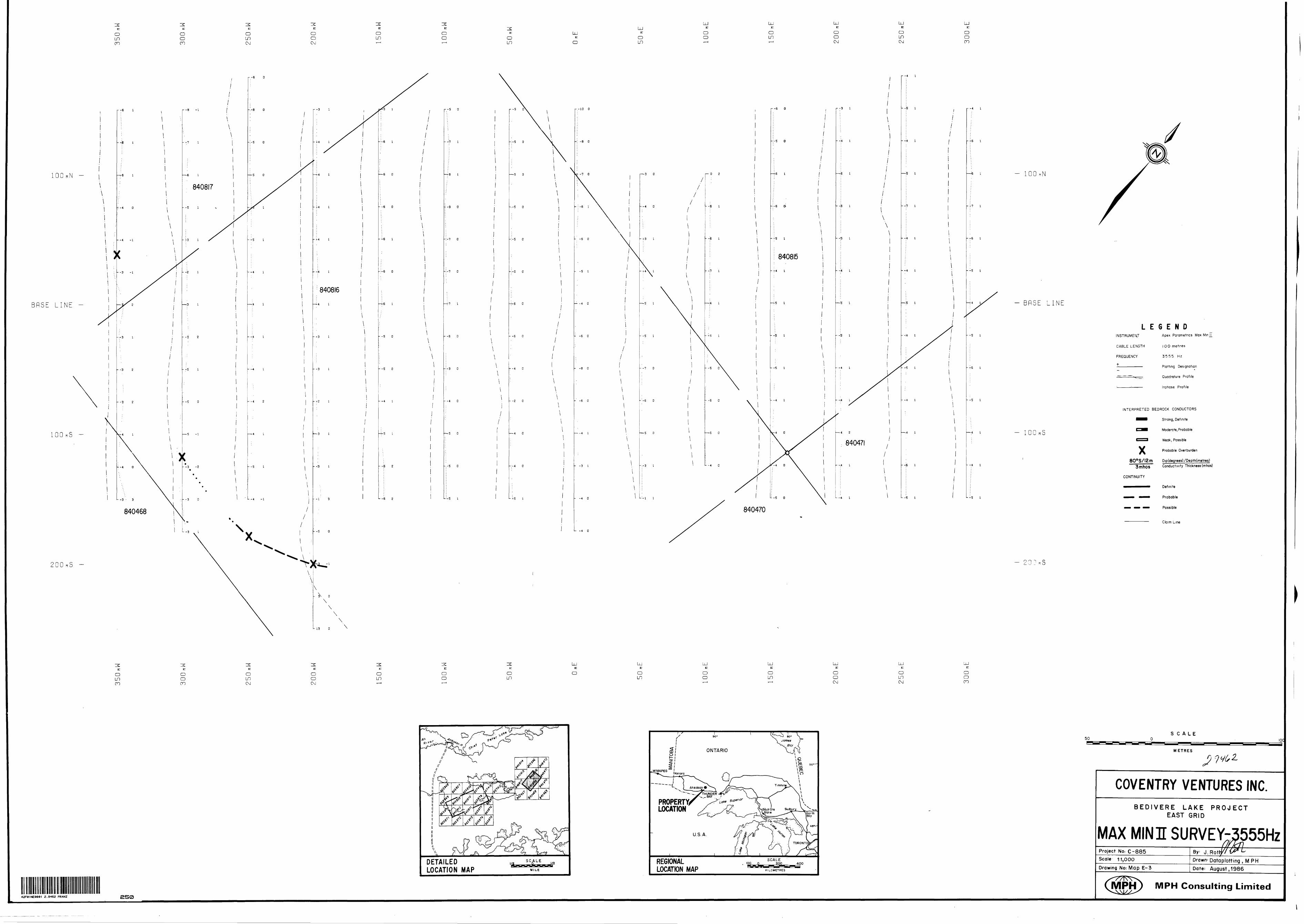
oLnon
oo en
o inC\J
o oCM
Oin
o o o
inLjJ
z:
ooun
LUz:
o o
LUz:
o in
LUc
O O CM
LUz:
OLOCM
LUr:o oCO
BflSE LINE -
lOOnS -
200nS -
r -4 l
r-S O
--r? i
— 8 l
' -9 'O
--t o
- -6 O
-:-3 o
- -4 O
— 5 O
-.-S Q
L -5 l
r -5
-:-s o
—5 O
-.-5 O
-:-s o
--5 O
— 6 O
- -6 O
r -4 o
- -2 O
— 4 O
-:-4 o
u -5 l
r -10 O
-: -8 o
\
- - -6 l
--60
- -5 l
— -4 O
-7 O
--60
-8 O
--60
— -4 l
- -3 l
--40
L. -4 O
i—3 O
— 4 O
- f 3 i
- -S l
- -7 O
- -6 O
-*-5 O
r -4 l
-T-6 l
--7 l
- -6 l
-'5 l
- -S l
- -5 l
- 100
- BRSE LINE
- 100
- -A l
L -5 l
o
LEGENDINSTRUMENT Apex Parametncs Max Mm J
CABLE LENGTH l 00 metres
FREQUENCY 3555 Hz
———————— Plotting Designation
—- —-—'• Vi — , Quadrature Profile
:————:—'— Inphase Profile
INTERPRETED BEDROCK CONDUCTORS
•••B Strong, Definite
^^•B Moderate, Probable
f"**"1 Weak, Possible
Probable Overburdenx800 SXI2m
3mhos
CONTINUITY
Dip(degrees)7Depth(metres) Conductivity Thickness (mhos)
Definite
Probable
Possible
Claim Line
O LOm
o oen
o unCM
O O CM
Oun
o o
irOun
oLU c
OLn
o o
LUz:o un
LU z:
OoCM
OLnCM
O Oen
DETAILED LOCATION MAP MILE
PROPERTY LOCATION
REGIONAL LOCATION MAP
42F81NE8081 2.9462 FRANZ 250
SCALE
METRES
COVENTRY VENTURES INC.BEDIVERE LAKE PROJECT
EAST GRID
MAX MIN J SURVEY-^555HzProject No: C-885Scale 1:1,000
Drawing No: Map E-3Drawn-Data p lotting , M PHDate; August, 1986
MPH) MPH Consulting Limited

o o r-
300nN -
200nN -
BnSE LINE -
r -6 l
- -7 2
lOOnS ~ —7 2
- T9 l
"- -7 l
200nS -
2.9462 FRANZ 260
o un CD
- -7 3
- -S l
\
//
-'-3 l
--5 2
1—6 2
Oin CD
o in in
o o in
o in
— •02
r -4 l
-:-4 l
—4 l
- -6 l
- T 7 l
- -1 2
--3 l
i 865870-6 2
-4: 2
— '5 2
-6 2
-5 l
—5 2
rS l
-6 l
r .-4 l
- -5 l
865869
; : o t - -6 l
!o l -:-7 o
—S l
:-4 l
:-s i
-i i
-4 2
-4 2
:-4 l
-S 2
-5 l
-10 l
-8 l
r o 2
— t 2
--5 l
-S l
-S l
-S l
-6 l
•7 l
-.7 2
-6 l
-6 l
—5 l
-:4 l
:-6 l
L- -2 l
Oun un
o o un
o un
o o
/l i \
- -10 i
\\
\\\
/
r -5 l
-S l
- -6 l
-6 l
: -B i
o o
.-S .1
— -4 l
:-6 l
-6 l
-6 l
-.-5 l
-5 l
-4 l
-4 l
-4 l
O O
o in en
o o on
LU E
O O
o in
o o in
LJn
o un un
--'4 \
—S /l
--4 l
--S l
-r5 l
— 4 O
r -4 2
-4 O
:-4 o
—-3 l
-4 l
-•4 l
-5 l
—5 i
-5 l
-4 l
\
Oun on
o o on
o unCM
O OCNJ
Oun
o o
o un
c Oun
o o
o un
o o CNJ
UJz:
Oun CNJ
o o on
UJz:
Oun on
o o
o un
UJr:
Ooun
UJz:
Oun un
UJn
OoCD
l—4 2
--S 2
-6 l
LU n
O O CD
- 300 MN
- 200nN
- 100 n
- BRSE LINE
- lOOnS
- 300
DETAILED LOCATION MAP
SCALE
MILE
PROPERTY LOCATION
REGIONAL LOCATION MAP
LEGEND
INSTRUMENT:
CABLE LENGTH
FREQUENCY^
PROFILE SCALE:
Apex Parametrics Max Mm
100 metres
3555 Hz
1 cm - 507o
Plotting Designation
Quadrature Profile
Inphase Profile
INTERPRETED BEDROCK CONDUCTORS
••B Strong, Definite
C^H Moderate, Probable
f~~l Weak, Possible
Probable Overburden
800SXI2m Dip(degrees)7Depth(metres) 3mhos Conductivity Thickness (mhos)
CONTINUITY
Definite
Probable
Possible
Claim Line
SCALE50
METRES
COVENTRY VENTURES INC
100
BEDIVERE LAKE PROJECT WEST GRID
MAX MINI SURVEY-3555 HzProject No: C-885Scale 1-.1,000
Drawing No: Map W-3
By J. RothDrawn: Data lotting , M PHDate-- August, 1986
MPH) MPH Consulting Limited