MANCHESTER - Platinum Airways
59
05 R 23 L 05 L 23 R HS1 HS1 Hot Spot HS1 Hold FZ1 has sharp turn from Twy V. Markings and stopbar lights may not be visible until close to the junction. Hot Spot HS2 Hold J1 faces 23R approach and is located 200m from the runway centreline. HS2 HS2 x x x PAPI (3°) MEHT 60 PAPI (3°) MEHT 62 PAPI (3°) MEHT 75 PAPI (3°) MEHT 75 PAPI (3°) MEHT 66 311 (54) 294 (37) 285 (28) 390 (133) 266 (9) VAR 1.5°W - 2017 N Annual Rate of Change 0.16°E 053°M 053°M 053°M 053°M 233°M 233°M 233°M 233°M 434 (177) 434 (177) Juliet Turning Circle Twy Q Twy K Twy L PIER B Twy D Twy C Twy C Twy B Exit BD Twy B Twy B Disused Disused Twy N Twy N Twy N Twy N Twy NA Twy NA Twy A Light Aircraft Area TATON Control Tower Terminal 1 Terminal 2 Terminal 2 Terminal 3 Terminal 3 Fire Station Customs Compass Swing Base Light Aircraft Area ROMPA ILS GP Radar Radar Engine Test Area Mid Turning Circle (B767 max) Fire Service Training Ground ILS GP ILS GP South Fire Station RVR RVR RVR RVR Anemometer Anemometer Anemometer 3048m x 45m 3048m x 45m 3048m x 45m Western Maintenance Exit AE Twy AF Twy AF T w y B Tw y V Tw y J Twy D Twy D Twy D Twy D Twy Y Twy W Twy T Twy J Twy J Twy G Twy G Disused Twy M Twy M Twy F Twy V Twy S Twy A Twy V T w y A G T w y H Twy JE Twy JF 3050m x45m Starter Extension 150m x 30m 274 (17) 255 T w y A T w y A New Control Tower New Control Tower Twy R Twy R PIER C Business Aviation Apron PIER A Blast Screen D3 D5 D6 D7 D1 M1 F1 J3 J2 C2 K1 K5 K4 C1 S1 L1 T1 U1 B1 G1 A1 Y1 W1 U2 A2 A3 A5 A4 B2 B3 B4 B6 J4 H2 L2 G2 G3 G4 F2 B5 AG1 AF1 VD1 VC1 HZ1 DZ1 VA2 VB2 FZ1 BZ1 VD2 VC2 NA1 VA1 VB1 H1 J1 V7 V6 V5 V4 V3 V1 K3 K2 Q1 N1 N3 D2 D4 100 0 100 200 300 400 500m 500 0 500 1000 1500ft Highest Elev in TDZ 231 532109.37N 0021638.35W (GUND Elevation 167) Highest Elev in TDZ 256 532126.41N 0021603.10W (GUND Elevation 167) Rwy 23R Thr Elev 249 532140.75N 0021533.41W (GUND Elevation 167) Rwy 05R Thr Elev 186 531955.10N 0021838.38W (GUND Elevation 167) MANCHESTER I-MM & I-NN 109.50 D (Ch 32X) MM NN 532111.39N 0021623.02W 263' MANCHESTER MCT 113.55 D (Ch 82Y) MCT 532125.29N 0021544.24W 282' MANCHESTER I-MC 111.55 D (Ch 52Y) IMC 531958.58N 0021820.74W 213' I-NN 109.50 D INN 532026.80N 0021806.41W I-MC 111.55 D IMC 532105.45N 0021612.92W I-MM 109.50 D IMM 532149.90N 0021514.46W Rwy 23L Thr Elev 227 532053.35N 0021637.95W GUND Elevation 167 (Highest Elev in TDZ) Rwy 05L Thr Elev 212 532051.20N 0021715.95W (GUND Elevation 167) Highest Elev in TDZ 189 532012.89N 0021801.61W (GUND Elevation 167) THR 05L/23R HI green with HI green W bars. THR 05R/23L HI green with HI green W bars. RWY 05L/23R HI bi-d edge. HI colour coded C/L. End lights red. TDZ 914m. RWY 05R/23L Elev HI bi-d with LI omni-d component. End lights red. TWY Green C/L, blue edge on sharp curves. Red stop bars at holding points. Green/yellow lead-off C/L to CAT III stop bars. LIGHTING BEARINGS ARE MAGNETIC ELEVATIONS AND HEIGHTS ARE IN FEET ELEVATIONS IN FEET AMSL 434 HEIGHTS IN FEET ABOVE AD (177) GUND (Geoid Undulation) = The height of the Geoid (MSL) above the Reference Elipsoid (WGS 84) at the stated position. COM ARRIVAL ATIS 128.175 MANCHESTER INFO DEPARTURE ATIS 121.975 MANCHESTER DEPARTURE INFO TWR 118.625 119.400 MANCHESTER TOWER 121.850 125.375 MANCHESTER GROUND 121.700 MANCHESTER DELIVERY 121.600 MANCHESTER FIRE RUNWAY/TAXIWAY/APRON PHYSICAL CHARACTERISTICS APRON / RWY / TWY SURFACE BEARING STRENGTH ELEVATION RWY 05L/23R Concrete/Ungrooved Asphalt 94/F/C/W/T - RWY 05R/23L Concrete/Grooved Asphalt 79/R/C/W/T - Apron Concrete 56/R/C/W/T - Apron Concrete 97/R/B/W/T - Taxiway A Concrete/Asphalt 66/F/C/W/T - Taxiway A (between AE & B) Concrete/Asphalt 46/F/C/W/T - Taxiway S/T/U Concrete/Asphalt 79/R/C/W/T - Taxiway V/VA Concrete/Asphalt 79/R/C/W/T - Taxiway VB/VC Concrete/Asphalt 79/R/C/W/T - Taxiway W/Y Concrete/Asphalt 79/R/C/W/T - Taxiway (All other) Concrete/Asphalt 95/R/C/W/T - AERO INFO DATE 2 MAR 16 MANCHESTER 532114N 0021630W ELEV 257FT AERODROME CHART - ICAO EGCC CHANGE (6/16): MAG VAR. APRON/TAXIWAY D EXENDED NORTH. CIVIL AVIATION AUTHORITY UNITED KINGDOM AIP AIRAC AMDT 6/2016 AD 2-EGCC-2-1 26 May 2016
-
Upload
khangminh22 -
Category
Documents
-
view
1 -
download
0
Transcript of MANCHESTER - Platinum Airways

05R
23 L
05L
23 R
HS1HS1
Hot SpotHS1 Hold FZ1 has sharp turnfrom Twy V. Markings andstopbar lights may not bevisible until close to thejunction.
Hot SpotHS2 Hold J1 faces 23Rapproach and is located200m from the runwaycentreline.
HS2HS2
xxxx
x
PAPI (3°)MEHT 60
PAPI (3°)MEHT 62
PAPI (3°)MEHT 75
PAPI (3°)MEHT 75
PAPI (3°)MEHT 66
311(54)
294(37)
285(28)
390(133)
266(9)
VAR
1.5
°W -
2017
NAnnual Rate
of Change 0.16°E
053°M053°M
053°M053°M
233°M233°M
233°M233°M
434(177)434(177)
JulietTurning Circle
Twy Q
Twy K
Twy
L
PIER
B
Twy D
Twy
C
Twy C Twy B
Exit BD
Twy B
Twy B
Disused
Disused
Twy NTwy N
Twy NTwy N
Twy NATwy NA
Twy A
LightAircraftArea
TATON
ControlTower
Terminal1
Terminal2
Terminal2
Terminal3
Terminal3
FireStation
Customs
Compass Swing BaseLight Aircraft Area ROMPA
ILSGP
Radar
Radar
Engine Test Area
Mid Turning Circle
(B767 max)
Fire ServiceTrainingGround
ILSGP
ILSGP
SouthFire Station
RVR
RVR
RVR
RVR
Anemometer
Anemometer
Anemometer
3048m x 45m3048m x 45m3048m x 45m
WesternMaintenance
Exit AE
Twy AF
Twy AF
Twy
B
Twy V
Twy J
Twy DTwy D
Twy DTwy D
Twy Y Twy W
Twy T
Twy J
Twy JTwy G
Twy G
Disuse
d
Twy M
Twy M
Twy F
Twy VTwy S
Twy A
Twy V
Twy
AG
Twy
H
Twy
JETw
y JF
3050m x45m
StarterExtension
150m x 30m
274(17)
255
Twy A
Twy A
NewControlTower
NewControlTower
Twy RTwy R
PIER C
BusinessAviation Apron
PIER
A
Blast Screen
D3
D5
D6
D7
D1
M1
F1
J3
J2
C2
K1
K5K4
C1
S1
L1
T1
U1
B1
G1
A1
Y1W1
U2
A2
A3
A5
A4
B2
B3 B4
B6J4
H2
L2
G2G3
G4
F2B5
AG1
AF1
VD1
VC1
HZ1
DZ1
VA2
VB2
FZ1
BZ1
VD2
VC2
NA1
VA1VB1
H1
J1
V7
V6
V5V4
V3
V1
K3
K2
Q1
N1
N3
D2
D4
100 0 100 200 300 400 500m
500 0 500 1000 1500ft
Highest Elev in TDZ 231532109.37N 0021638.35W
(GUND Elevation 167)
Highest Elev in TDZ 256532126.41N 0021603.10W
(GUND Elevation 167)
Rwy 23R Thr Elev 249532140.75N 0021533.41W
(GUND Elevation 167)
Rwy 05R Thr Elev 186531955.10N 0021838.38W
(GUND Elevation 167)
MANCHESTERI-MM & I-NN
109.50D
(Ch 32X)MM NN
532111.39N 0021623.02W263'
MANCHESTERMCT 113.55D
(Ch 82Y)MCT
532125.29N 0021544.24W282'
MANCHESTERI-MC 111.55D
(Ch 52Y)IMC
531958.58N 0021820.74W213'
I-NN 109.50D
INN
532026.80N 0021806.41WI-MC 111.55D
IMC
532105.45N 0021612.92W
I-MM 109.50D
IMM
532149.90N 0021514.46W
Rwy 23L Thr Elev 227532053.35N 0021637.95W
GUND Elevation 167(Highest Elev in TDZ)
Rwy 05L Thr Elev 212532051.20N 0021715.95W
(GUND Elevation 167)
Highest Elev in TDZ 189532012.89N 0021801.61W
(GUND Elevation 167)
THR 05L/23R HI green with HI green W bars.THR 05R/23L HI green with HI green W bars.
RWY 05L/23R HI bi-d edge. HI colour coded C/L. End lights red. TDZ 914m.RWY 05R/23L Elev HI bi-d with LI omni-d component. End lights red.
TWY Green C/L, blue edge on sharp curves. Red stop bars at holding points. Green/yellow lead-off C/L to CAT III stop bars.
LIGHTING
BEARINGS ARE MAGNETICELEVATIONS AND HEIGHTS ARE IN FEET
ELEVATIONS IN FEET AMSL 434HEIGHTS IN FEET ABOVE AD (177)
GUND (Geoid Undulation) =The height of the Geoid (MSL) above the
Reference Elipsoid (WGS 84) at the stated position.
COMARRIVAL ATIS 128.175 MANCHESTER INFODEPARTURE ATIS 121.975 MANCHESTER DEPARTURE INFOTWR 118.625 119.400 MANCHESTER TOWER 121.850 125.375 MANCHESTER GROUND 121.700 MANCHESTER DELIVERY 121.600 MANCHESTER FIRE
RUNWAY/TAXIWAY/APRON PHYSICAL CHARACTERISTICSAPRON / RWY / TWY SURFACE BEARING STRENGTH ELEVATIONRWY 05L/23R Concrete/Ungrooved Asphalt 94/F/C/W/T -RWY 05R/23L Concrete/Grooved Asphalt 79/R/C/W/T -Apron Concrete 56/R/C/W/T -Apron Concrete 97/R/B/W/T -Taxiway A Concrete/Asphalt 66/F/C/W/T -Taxiway A (between AE & B) Concrete/Asphalt 46/F/C/W/T -Taxiway S/T/U Concrete/Asphalt 79/R/C/W/T -Taxiway V/VA Concrete/Asphalt 79/R/C/W/T -Taxiway VB/VC Concrete/Asphalt 79/R/C/W/T -Taxiway W/Y Concrete/Asphalt 79/R/C/W/T -Taxiway (All other) Concrete/Asphalt 95/R/C/W/T -
AERO INFO DATE 2 MAR 16
MANCHESTER532114N 0021630W ELEV 257FTAERODROMECHART - ICAO EGCC
CHANGE (6/16): MAG VAR. APRON/TAXIWAY D EXENDED NORTH.
CIV
ILA
VIA
TIO
NA
UT
HO
RIT
Y
UN
ITE
DK
ING
DO
MA
IP
AIR
AC
AM
DT
6/2016
AD
2-EG
CC
-2-126
May
2016

Dis
used
Disused
Disused
11
9
1512
2832
262231
16 172
7
5
1
24
63
2729
62
6161 8
6
10
23
21
4
25 55
54
100100
210210
216216217217
247247
249249
218218
219219
215215
53
5657
58
44
4349
47
203203202202
48
5150
52
243243241241
239239
233233
237237
235235
1841
42
211211
214214
212212213213213213
205205204204
208208209209209209
207207206206
8585
8686
85
8080
8484
8383
8181
8282
676767
686868
696969
64646464
656565
666666
86
707070
717171
727272
737373
747474
80
84
83
81
82
201201
101101
231231
NAnnual Rate
of Change 0.16°E
VAR
1.5°W - 2017
Hot SpotHS2 Hold J1 faces 23Rapproach and is located200m from the runwaycentreline.
HS2HS2
Hot SpotHS1 Hold FZ1 has sharp turnfrom Twy V. Markings andstopbar lights may not bevisible until close to thejunction.
HS1HS1
F1
N1
D5
L2
V1
G3
B3 D2
D4
D3 B4
B5
B6
J4
F2
H2
A5
L1
J3
J2
K2
K3K4
J1
H1
G1
M1
D1
N3
NA1
HZ1
A4
Q1
C2K1
D6
D7
G2 G4
K5
FZ1
C1
Novem
be
r-Alph
a
Novem
be
r-Alph
a
Twy NTwy N
Twy DTwy D
Twy DTwy D
Twy DTwy D
Customs
Terminal 2
Terminal 1
Terminal3
ControlTower
NewControlTower
NewControlTower
CargoArea
Twy NTwy N
Twy D
Twy D
WesternApron
WesternApron
Terminal 3 (Domestic)
Twy RTwy R
Twy MTwy M
Twy JTwy J
Twy J
Twy J
Twy JF
Twy JF Tw
y JE
Twy
JE
Twy QTwy QTwy Q
Disused
BlastFence
Blast S
creen
Twy
CTw
y C
Twy P
Twy P
Twy KTwy K
Twy BTwy B
Twy FTwy F
Twy
ATw
y A
Twy GTwy G
Twy GTwy G
Twy CTwy C
Twy
LTw
y L
BusinessAviationApron
BusinessAviationApron
WesternMaintenance
WesternMaintenance
RWY 05L/23R
RWY 05L/23R
Twy H
Twy H
EngineTestArea
EngineTestArea
Twy DTwy DTwy DTwy DTwy DTwy DTwy DTwy DTwy D
PIER
B
PIER C
FireStation
PIE
R A
50 500 100 150m
500ft0100
STAND COORDINATE 208L 532157.33N 0021646.63W 208 532157.35N 0021645.75W 209 532158.18N 0021648.72W 210L 532159.53N 0021650.00W 210 532159.42N 0021649.32W 211 532200.27N 0021652.26W 212L 532201.61N 0021653.55W 212 532201.56N 0021652.89W 213 532202.37N 0021655.79W 214L 532203.72N 0021657.06W 214 532203.67N 0021656.41W 215 532204.89N 0021658.84W Terminal 2 Remote 216 To be surveyed 216R 532206.32N 0021701.04W 217 532207.61N 0021703.20W 218 To be surveyed 219 To be surveyed 231 532150.58N 0021650.74W 233 532152.54N 0021654.05W 235 532153.66N 0021655.92W 237 532154.82N 0021657.88W 239 532156.23N 0021700.26W 241 532157.57N 0021702.00W 243 532158.53N 0021703.61W 247 To be surveyed 249 To be surveyed
STAND COORDINATE 83L 532155.69N 0021703.37W 83 532155.23N 0021702.58W 83R 532154.76N 0021701.80W 84L 532157.56N 0021706.51W 84 532157.09N 0021705.73W 84R 532156.63N 0021704.94W 85L 532201.24N 0021713.93W 85 532200.74N 0021712.65W 85R 532200.27N 0021712.32W 86L 532203.24N 0021717.31W 86 532202.67N 0021715.88W 86R 532202.24N 0021715.62W 100 532136.02N 0021637.49W 101 532132.54N 0021638.00W Terminal 2 201 532150.51N 0021634.67W 202L 532151.11N 0021636.29W 202 532151.25N 0021635.03W 203 532152.17N 0021637.67W 204L 532153.21N 0021639.82W 204 532153.10N 0021638.77W 205 532153.99N 0021641.66W 206L 532155.23N 0021643.10W 206 532155.23N 0021642.25W 207 532156.12N 0021645.13W
STAND COORDINATE 69R 532149.54N 0021709.75W 70L 532150.47N 0021711.32W 70 532150.94N 0021712.11W 70R 532151.40N 0021712.90W 71L 532152.34N 0021714.47W 71 532152.81N 0021715.26W 71R 532153.27N 0021716.05W 72L 532154.02N 0021718.57W 72 532154.57N 0021719.71W 72R 532154.98N 0021720.19W 73L 532155.94N 0021721.82W 73 532156.44N 0021723.08W 73R 532156.91N 0021723.44W 74L 532157.87N 0021725.05W 74 532158.38N 0021726.30W 74R 532158.83N 0021726.67W 80L To be surveyed 80 532149.85N 0021653.02W 80R To be surveyed 81L To be surveyed 81 532151.49N 0021656.29W 81R To be surveyed 82L 532153.83N 0021700.22W 82 532153.38N 0021659.40W 82R 532152.89N 0021658.65W
STAND COORDINATE 61 532133.60N 0021649.22W 61R 532134.75N 0021648.16W 62 532136.77N 0021648.20W 62L 532136.28N 0021646.83W 62R 532137.20N 0021647.21W 63 532137.91N 0021650.29W 63L 532137.55N 0021649.49W 63R 532138.52N 0021650.73W 64 532139.64N 0021653.14W 64L 532139.54N 0021651.90W 64R 532140.23N 0021653.61W 65R 532142.55N 0021656.23W 65 532141.60N 0021655.60W 65L 532141.70N 0021654.77W 66L 532143.02N 0021658.70W 66 532143.39N 0021659.64W 66R 532143.93N 0021700.31W 67L 532144.98N 0021701.69W 67 532145.34N 0021702.67W 67R 532145.80N 0021703.45W 68L 532146.85N 0021704.84W 68 532147.07N 0021706.03W 68R 532147.67N 0021706.60W 69L 532148.72N 0021707.99W 69 532149.07N 0021708.96W
STAND COORDINATE 28 532145.90N 0021642.40W 29 532143.47N 0021643.17W 31 532144.58N 0021644.84W 32 532145.73N 0021643.95W Terminal 3 41 532137.93N 0021616.22W 42 532136.08N 0021615.75W 43 532134.20N 0021615.73W 44L 532133.04N 0021615.99W 44 532133.03N 0021615.00W 44R 532132.11N 0021615.44W 47 532132.53N 0021613.60W 48 532133.42N 0021612.63W 49 532135.40N 0021612.42W 50 To be surveyed 51 532137.82N 0021608.49W 52 532138.67N 0021607.15W 53 532139.64N 0021605.53W 54 532140.75N 0021603.75W 55 532142.16N 0021601.11W 56 532141.75N 0021558.90W 57 532140.98N 0021557.50W 58 532140.16N 0021556.67W West Apron 61L 532132.33N 0021648.46W
STAND COORDINATE Terminal 1 1 532138.99N 0021626.70W 2 532138.77N 0021629.89W 4 532137.10N 0021629.72W 5 532136.63N 0021626.85W 6 532135.22N 0021629.54W 7 532135.40N 0021627.33W 8 532133.47N 0021630.04W 9 532133.77N 0021627.44W 10 532131.73N 0021630.16W 11 532132.25N 0021627.50W 12 532129.39N 0021629.43W 12L 532129.75N 0021630.62W 12R 532128.91N 0021629.21W 15 532130.37N 0021627.27W 16 532139.29N 0021622.99W 17 532139.48N 0021620.95W 18 532139.25N 0021618.00W 21 532140.68N 0021630.84W 22 532143.85N 0021634.46W 23 532142.12N 0021634.04W 24 532144.49N 0021637.14W 25 532142.48N 0021636.90W 26 532144.74N 0021639.99W 27 532142.83N 0021638.80W
RUNWAY/TAXIWAY/APRON PHYSICAL CHARACTERISTICSAPRON / RWY / TWY SURFACE BEARING STRENGTH ELEVATIONRWY 05L/23R Concrete/Ungrooved Asphalt 94/F/C/W/T -RWY 05R/23L Concrete/Grooved Asphalt 79/R/C/W/T -Apron Concrete 56/R/C/W/T -Apron Concrete 97/R/B/W/T -Taxiway A Concrete/Asphalt 66/F/C/W/T -Taxiway A (between AE & B) Concrete/Asphalt 46/F/C/W/T -Taxiway S/T/U Concrete/Asphalt 79/R/C/W/T -Taxiway V/VA Concrete/Asphalt 79/R/C/W/T -Taxiway VB/VC Concrete/Asphalt 79/R/C/W/T -Taxiway W/Y Concrete/Asphalt 79/R/C/W/T -Taxiway (All other) Concrete/Asphalt 95/R/C/W/T -
COMARRIVAL ATIS 128.175 MANCHESTER INFODEPARTURE ATIS 121.975 MANCHESTER DEPARTURE INFOTWR 118.625 119.400 MANCHESTER TOWER 121.850 125.375 MANCHESTER GROUND 121.700 MANCHESTER DELIVERY 121.600 MANCHESTER FIRE
AERO INFO DATE 2 MAR 16
CHART - ICAOAIRCRAFT PARKING/DOCKING MANCHESTER
EGCCELEV 257FT532114N 0021630W
CHANGE (6/16): MAG VAR. APRON/TAXIWAY D EXTENDED NORTH. STANDS 50/80L/80R/81L/81R/217/218/219/247/249 ADDED. STAND 217 COORDINATE ADDED. CENTRELINES.
CIV
ILA
VIA
TIO
NA
UT
HO
RIT
Y
UN
ITE
DK
ING
DO
MA
IP
AIR
AC
AM
DT
6/2016
AD
2-EG
CC
-2-226
May
2016

05R
23 L
05L
23 R
xxxx
x
NAnnual Rate
of Change 0.16°E
VAR
2.0
°W -
2015
HS1HS1
Hot SpotHS1 Hold FZ1 has sharp turnfrom Twy V. Markings andstopbar lights may not bevisible until close to thejunction.
Hot SpotHS2 Hold J1 faces 23Rapproach and is located200m from the runwaycentreline.
HS2HS2
JulietTurning Circle
(747 max)
Twy Q
Twy K
Twy
L
Twy D
Twy
C
Twy CTwy B
Exit BD
Twy B
Twy B
Twy
A
TwyG
Disused
Twy A
LightAircraftArea
TATON
ControlTower
NewControlTower
NewControlTower
Terminal1
Terminal3
Terminal3
FireStation
Compass Swing BaseLight Aircraft Area ROMPA
Engine Test Area
Mid Turning Circle(B767 max)
Fire ServiceTrainingGround
SouthFire Station
3048m x 45m
3048m x 45m
3048m x 45m
WesternMaintenance
Exit AE
Twy V
Twy Y
Twy W
Twy
T
Twy J
Twy J
Disu
sed
Disused
Disused
Twy F
Twy VTwy S
Twy A
Twy V
Twy
H
Twy
JE
Twy
JF
3050m x45m
Twy AG
Twy MTwy MTwy M
BusinessAviation Apron
PIER
B
PIER
A
L1
D2
D4
L2D5
H2
G2G3
G4 M1J3
H1
B1
U2
A2
A3
A4
A5
AF1
DZ1
VB2
BZ1
VB1
HZ1
FZ1
G1G1
C2
K5 K4C1
K1
B2
B6 J4B5
B4
B3
F2
D3
J2 J1
T1
U1A1
Y1
W1
AG1
VD1
VC1
VA2
VD2
VC2
VA1
D1
F1
V7
V6
V5
S1
V4 V3
V1
K3K2
Q1
Twy B
TwyAFTwyAF
100 0 100 200 300 400 500m
500 0 500 1000 1500ft
A380 Ground Movement
Aprons
Operational Taxiways
AERO INFO DATE 5 JAN 16
MANCHESTER532114N 0021630W ELEV 257FTEGCC
AERODROME CHARTA380 GROUND MOVEMENT - ICAO
CHANGE (4/16): HOTSPOTS HS1 & HS2 ADDED.
CIV
ILA
VIA
TIO
NA
UT
HO
RIT
Y
UN
ITE
DK
ING
DO
MA
IP
AIR
AC
AM
DT
4/2016
AD
2-EG
CC
-2-331
Mar
2016

MANCHESTERCTR D
L70 CL70 C FL195FL195FL85FL85
D3043500SFC
D3142900SFC
R3191700SFC
R311R31122002200SFCSFC
R3112200SFC
R312R31221002100SFCSFC
R3122100SFC
BLACKPOOLBLACKPOOLBLACKPOOL
WARTONWARTONWARTON
WOODVALEWOODVALEWOODVALE
HAWARDEN
WOODFORDWOODFORDWOODFORD
MANCHESTERMANCHESTERMANCHESTER
MANCHESTER/MANCHESTER/BartonBarton
MANCHESTER/Barton
LIVERPOOL LIVERPOOL LIVERPOOL
MANCHESTERTMA-1 A
MANCHESTERTMA-2 A
MANCHESTERMANCHESTERTMA-1 A TMA-1 A
MANCHESTERTMA-1 A
MANCHESTERMANCHESTERTMA-1 A TMA-1 A
MANCHESTERTMA-1 A MANCHESTERMANCHESTER
TMA-1 A TMA-1 A MANCHESTER
TMA-1 A
MANCHESTERMANCHESTERTMA-1 A TMA-1 A
MANCHESTERTMA-1 A
MANCHESTERCTA-1 D
MANCHESTERCTA-1 D
MANCHESTERCTA-4 D
MANCHESTERCTA-4 D
MANCHESTERMANCHESTERCTA-5 D CTA-5 D
MANCHESTERCTA-5 D
MANCHESTERCTA-2 D
MANCHESTERCTA-2 D
MANCHESTERCTA-3 D
MANCHESTERCTA-3 D
LIVERPOOLLIVERPOOLCTA-3 D CTA-3 D
LIVERPOOLCTA-3 D
LIVERPOOLCTA-2 D
LIVERPOOLCTA-4 D
CTA-1 D
CTA-1 D
CTA-1 D LIVERPOOLLIVERPOOL
CTR D CTR D LIVERPOOL
CTR D
MANCHESTERCTR D
FL1953500L975 A
FL852500
CTA D
FL195FL145
L70 C
FL195FL85L70 C
FL195FL85L70 C
FL195FL195FL155FL155
N864 A
N864 A
FL195FL155
N864 A
FL195FL65
L612 A
FL19
545
00
DAVE
NTRY
CTA
AFL
195
5500
DAVE
NTRY
CTA
A
FL19
555
00
DAVE
NTRY
CTA
A
N57 AFL195FL55
N57 AFL1954500
LEEDSBRADFORD
CTA DFL853000
LEEDSBRADFORD
CTR DFL85SFC
N864 AFL1953000
N864 AFL1953000
L10/L975 AFL1953500
N864 AFL1954500
FL1954500
DAVENTRYCTA A
DAVENTRYCTA A
FL85-FL195
DAVENTRY
CTA A
FL65-FL195
NAnnual Rate
of Change 0.16°E
VAR
2.0°W - 2015
003 00W003 00W003 00W 002 30W
003 00W 002 30W
5330N5330N5330N 5330N
002 00W002 00W002 00W
002 00W
CHANGE (2/15): MAG VAR. WOODFORD DISUSED AERODROME SYMBOL ADDED.
AERO INFO DATE 12 NOV 14
ATS AIRSPACE VERTICAL LIMITS Controlled airspace with an upper vertical limit of FL195 and above is not shown.
LATERAL LIMITS
10 0 10NM
MANCHESTER CTR D 3500 SFC
CTA-1 D 3500 2500
CTA-2 D 3500 2500
CTA-3 D 3500 3000
CTA-4 D 3500 2500
CTA-5 D 3500 2000
See AD 2-EGCC 2.17 See AD 2-EGGP 2.17 See Manchester TMA ENR 2.1
LIVERPOOL CTR D 2500 SFC
CTA-1 D 3500 1500
CTA-2 D 3500 2000
CTA-3 D 3500 2500
CTA-4 D 3000 2000
MANCHESTER TMA-1 A FL195 3500
TMA-2 A FL145 FL55
(MNM 5000)
Scale 1:625 000
CONTROL ZONE AND CONTROL AREA MANCHESTER
UNITED KINGDOM AIP AD 2-EGCC-3-15 Feb 2015
CIVIL AVIATION AUTHORITY AMDT 2/2015

MANCHESTER/Barton
LISTOSANBA
MCT113.55
MANCHESTER
Land above500FT AAL
Land above500FT AAL
SANBA 1R 1Y
05R
23L
23L
23L
05L05L05L
23R
23R
23R
LISTO 2YLISTO
2R
LIST
O 2
S 2Z
EKLAD/MONTY/KUXEM 1R 1Y
MONTY/ASMIM 1S 1Z
POL 5
R 1Y
POL 4S 1Z
SONEX 1R 1Y
DESIG 1S 1Z
SONEX532953N 0021021WWAL R081.6/D35.1POL R191.8/D15.0
WOODFORD
Noise Monitoring Terminals (NMT)Only Noise Monitoring Terminals used for Infringement/Rebate purposes are shown.Distance to run to the appropriate NMT is in nautical milesfrom take-off position which gives maximum TORA.
RWY NMT NM 23R 1 3.4 3 3.4 2 3.8
26
1
2 3
67
2122
5330N
002 00W002 30W002 30W002 30W
002 00W002 30W
5330N5330N5330N
NAnnual Rate
of Change 0.16°E
VA
R 3.4°W
- 2006V
AR
3.4°W - 2006
VA
R 2.0°W
- 2015
5 0 5NM
RWY NMT NM 23L 21 3.5 22 3.5
RWY NMT NM 05L 7 3.4 6 3.7
RWY NMT NM 05R 26 3.5
6
Scale 1:250 000
NOISE PREFERENTIAL ROUTEINGS MANCHESTER
AERO INFO DATE 27 FEB 15CHANGE (6/15): SID LIVSU REPLACED BY EKLAD.
UNITED KINGDOM AIP AD 2-EGCC-3-228 May 2015
CIVIL AVIATION AUTHORITY AMDT 6/2015

1
34
5
6
5
4
1
1
220
21
22
3
19
19
18
17
16
1425
24
23
22
10
10
10
11
11
11/15
12
12
14
12
11
9
9
9
5
4
8
8
7
7
6
24
23
1
13
33
2527
19
18
17
6
21
20
5
5
27
26
6
5
3
3
2
22a
1
5
67
7
GVS3100SFC
D3043500SFC
D3142900SFC
R3112200SFC
R3191700SFC
1004
1908
1775
945
576994
1348
1345
1083
1834
2087
1324
1339
1165
1125 1657
35
5
4
1
319
18
17
16
14
10
11
11
11/15
12
12
14
12
11
9
9
9
5
4
8
8
7
7
6
24
23
1
13
33
2527
19
18
17
6
21
20
5
5
26
6
5
3
3
2
22a
1
5
67
7
24
23
22
10
10
25
5
GVS3100SFCC
R311112200SFC
R319R31917001700SFCFC
1908
1775
945
576
1348
1345
1834
2087
1324
1125 1657
23L/23R23L/23R23L/23R
670670(563)(563)670(563) 633633
(492)(492)633(492)
600600(394)(394)600(394)
002 00W002 30W003 00W003 00W003 00W
00200W00200W00200W002 30W002 30W002 30W003 00W
5330N5330N
E/E VRPE/E VRPSTRETTON ADSTRETTON AD
E/E VRPSTRETTON AD
VRPVRPSWINTONSWINTON
INTERCHANGEINTERCHANGE
VRPSWINTON
INTERCHANGE
VRPM60/M62/M66
HEATONINTERCHANGE
VRPALDERLEYEDGE HILL
VRPJODRELL
BANK
VRPLAMALOADRESERVOIR
VRPDOVESTONESRESERVOIRS
VRPWHALEYBRIDGE
E/E VRPE/E VRPMACCLESFIELDMACCLESFIELD
SOUTHSOUTH
E/E VRPMACCLESFIELD
SOUTH
VRPVRPHOLMESHOLMESCHAPELCHAPEL
VRPHOLMESCHAPEL
VRPVRPVRPBEESTONCASTLE
VRPVRPVRPPOULTONDISUSED
AERODROME
VRPVRPVRPPADESWOOD
CEMENTFACTORY
VRPVRPVRPFLINT
BRIDGE
VRPVRPVRPMOLDTOWN
E/EE/ENESTONNESTON
LANELANE
E/ENESTON
LANE
E/E VRPTHELWALLVIADUCT
E/EE/EMERSEYMERSEY
LANELANE
E/EMERSEY
LANE
E/EE/EAINTREEAINTREE
R'CSER'CSE
E/EAINTREE
R'CSEVRP
HAYDOCKPARK R'CSE
VRPLEIGHFLASH
VRPBUXTON
VRPVRPHILLTOPHILLTOP
VRPHILLTOP
VRPROSTHERNE
VRPVRPSALE WATER PkSALE WATER Pk
VRPSALE WATER Pk
VRPGLOSSOP
VRPVRPIRLAMIRLAM
VRPIRLAM
VRPOULTON PARK
VRPCHESTER
VRPWINSFORD
FLASH
VRPREEBOKSTADIUM
VRPNESTON
VRPVRPKIRKBYKIRKBY
VRPKIRKBY
VRPBURTONWOOD
VRPVRPSEAFORTHSEAFORTH
VRPSEAFORTH
VRPFORMBY POINT
M53
M57
M6
M6M6
M56
M60M60
M60
M6
M62
M62
M56
M56
M56
M53
A51
A55
M58
M6
M61
M66
M60
M62
WOODVALEWOODVALEWOODVALE
MARTIN MERE2000SFC
HILBREISLANDS
500SFC
INCE
MANCHESTER SHIP CANAL
MANCHESTER SHIP CANAL
MANCHESTER SHIP CANAL
2452(1015)
875(350)
1696(328)
407(263)
529529(398)(398)529(398)
659(321)
391391(351)(351)391(351)
431(375)
434(391)
654(604)
475(450)
375(332)
327(320)
377377(370)(370)377(370)
526(512)
490(467)
418(408)
403(380)
472472(393)(393)472(393)
540(300)
594(361)
397
774(390)
364364(335)(335)364(335)
798(300)
427427427
285
1637(520)
560(305)
505505(354)(354)505(354)
466466(371)(371)466(371)
506(368)512
(479)
634634(502)(502)634(502)
421421(388)(388)421(388) 466466
(305)(305)466(305)
450450(355)(355)450(355)
326326(306)(306)326(306)
343343(321)(321)343(321)
378(300)
349(318)
392(392)
STANEDGESTANEDGESTANEDGE
ASHCROFT
ARCLID
WAVERTON
HAWARDEN HAW
HAWARDEN ATZ
WAL
LPL
STRETTON
MANCHESTERWOODFORD
MANCHESTERMANCHESTERMANCHESTER
MANCHESTER/MANCHESTER/BartonBarton
MANCHESTER/Barton
WOO
DV
ALE ATZ
MCTWFD
WHI
BARTON ATZ
BARTON ATZ
LIVERPOOLLIVERPOOLLIVERPOOL
27 09
272727
05L/05R
23L/23R
23L/23R
05L/05R
09
2709
2709
VRPM56
JUNC 10VRPM56
JUNC 11
VRPVRPCONGLETONCONGLETON
VRPCONGLETON
All Local and Lane Flyingto be below cloud and insight of ground or water.
LIVERPOOL L.F.A.MAX ALT 1500'Liverpool QNHMnm Vis 3kmClearance by
Liverpool ATC.
LOW LEVEL ROUTE D MAX ALT 1300'MANCHESTER QNH
LOW LEVEL ROUTE D MAX ALT 1300'MANCHESTER QNH
MACCLESFIELDENTRY/EXIT LANE
Aircraft must not leavethe confines of the Entry/
Exit lane without priorco-ordination with ATC
WARNINGRising high ground to theeast of the Entry/Exit lane
NAnnual Rate
of Change 0.16°E
CONTROL ZONE AND CONTROL AREA CHART - ENTRY/EXIT LANES AND VRPs MANCHESTER
AERO INFO DATE 30 APR 14CHANGE (8/14): LIVERPOOL CTA. MAG VAR.
5 0 5NM
Controlled airspace with an upper vertical limit of FL195 and above isnot shown.
VAR
2.3°W - 2014
VAR
2.3°W - 2014
VAR
2.1°W - 2014
MANCHESTER CTR D 3500 SFC
LIVERPOOL CTA-1 D 3500 1500
LIVERPOOL CTA-2 D 3500 2000
LIVERPOOL CTA-4 D 3000 2000
MANCHESTER CTA-4 D 3500 2500
MANCHESTER CTA-5 D 3500 2000
AIRWAY N864 A FL195 3000
AIRWAY N864 A FL195 3000
AIRWAY L10 A FL195 3500
AIRWAY L70 C FL195 FL85
AIRWAY L70 C FL195 FL85
AIRWAY L70 C FL195 FL145
AIRWAY N864 A FL195 FL155
DAVENTRY CTA A FL195 4500
DAVENTRY CTA A FL195 4500
DA
VENT
RY
CTA
A
FL19
5
55
00
MANCHESTER TMA-1 A FL195 3500
MANCHESTER TMA-1 A FL195 3500
MANCHESTER CTA-3 D 3500 3000
MANCHESTER TMA-1 A FL195 3500
MANCHESTER CTR D 3500 SFC
MANCHESTER TMA-1 A FL195 3500
MANCHESTER CTA-2 D 3500 2500
MANCHESTER TMA-1 A FL195 3500
MANCHESTER TMA-2 A FL145 FL55 (MNM 5000)
LIVERPOOL CTR D 2500 SFC
MANCHESTER TMA-1 A FL195 3500
MANCHESTER TMA-1 A FL195 3500
MANCHESTER CTA-1 D 3500 2500
LIVERPOOL CTA-3 D 3500 2500
CIV
ILA
VIA
TIO
NA
UT
HO
RIT
Y
UN
ITE
DK
ING
DO
MA
IPA
D2-E
GC
C-4-1
AM
DT
8/2014
24Jul2014

05R
05L 24
R 24
R 23
R
23L
R3191700SFC
GVS2600SFC
D3142900SFC
D3043500SFC
360°
360°
180°
180°
35002800
3100
3500
2900
2900
3100
31002900
3100
24002400
2400
2400
3500
2400
2400
2400
2400
2400
1600
1600
090°
270°
180°
360°
552
588
745
1102
1125
1264
1519
1657
160416041604
1312 12721272
1247 1289
1296
13781473
1659
1028
1345
1338
107310731073
945
285285285
179517951795181018101810
1683
1437
132213221322
154515451545
1696
1867
20871937
1759175917591785
2060
2037
2077
1775
1908
1641
142714801283
1244
994
15371010
1293129312931309
2047
1348
16221483 1545
1805
154315431543
1663
851
570
515
183418341834
LOW
LEVEL RO
UTE D
LOW
LEVEL RO
UTE D
MA
X ALT 1300 M
AN
QN
HM
AX A
LT 1300 MA
N Q
NH
MAN
CHES
TER
CTA
D
MAN
CHES
TER
CTA
D35
0035
0030
0030
00
MANCHESTERMANCHESTERCTA DCTA D3500350025002500
MANCHESTERMANCHESTERCTA DCTA D3500350020002000
MANCHESTERMANCHESTERTMA ATMA AFL195FL19535003500
5330N
002 00W
CTA D35002500
002 30W
002 00W002 00W002 30W002 30W002 30W
5330N
MANCHESTERTMA AFL1953500
MANCHESTERMANCHESTERTMA ATMA AFL195FL19535003500
MANCHESTERTMA AFL1953500
DAVENTRY CTA AFL1954500Y53 A 3500+
MANCHESTERCTA D35002500
LIVERPOOLCTR D2500SFC
MANCHESTERCTA D35002000
MANCHESTERMANCHESTERCTR DCTR D35003500SFCSFC
MANCHESTERCTR D3500SFC
MANCHESTERTMA AFL1953500
MANCHESTERTMA AFL1953500
MANCHESTERCTA D35002500
DAVENTRYCTA AFL1954500
MANCHESTERTMA AFL1953500
MAN
CHES
TER
CTA
D35
0030
00
LOW
LEVEL RO
UTE D
MA
X ALT 1300 M
AN
QN
H
WOODFORDWOODFORD
528528(381)(381)528(381)
526526(398)(398)526(398)
MCT R112MCT R112MCT R111
714(162)
505(391)
407(263)
426(351)
476(358)
678678(563)(563)678(563) 544
(403)
560(305)
1263(164)
396711
326
332
375(300)
778(220)
496(226)
495(245)
337337(84)(84)337(84)
489489(253)(253)489(253)
774774(390)(390)774(390)
10471047(151)(151)1047(151)
766(392)
469(450)
654(604)
390(353)
393(344)
788(300)
12491249(378)(378)1249(378)
1555(243)
1801(118)
15841584(35)(35)
1584(35)
1351(68)
850(545)
2502(771)
1414
WHI
LPL
AMLET
MCT
MANCHESTER/Barton
MANCHESTERMANCHESTERMANCHESTERSTRETTON
WARRINGTON
STANEDGESTANEDGESTANEDGE
ASHCROFT
ARCLID
DAYNEDAYNEDAYNE
MCT R133
MCT R133
MCT R132
WOODFORD
VAR
2.0°W - 2015
NAnnual Rate
of Change 0.16°E
MINIMUM INITIAL ALTITUDEWithin the ATC Surveillance Minimum Altitude area the minimum initial altitude to be allocated by the approach surveillance controller is: a) 2400 in the sector defined by the lateral limits; 533037N 0023746W - 533351N 0020941W - 532541N 0015838W - 531358N 0021029W - thence anti-clockwise by an arc of a circle radius 3.1NM centred on 531222N 0020603W to 530916N 0020558W - 530706N 0020723W - 531108N 0023744W - 533037N 0023746W. b) 2800 in the sector defined by the lateral limits; 533351N 0020941W - 533430N 0020400W - 532906N 0015617W - 532541N 0015838W - 533351N 0020941W. c) 2900 in the sector defined by the lateral limits; 532406N 0020014W - 532207N 0015735W - 530916N 0020558W thence clockwise by an arc of a circle radius 3.1NM centred on 531222N 0020603W to 531358N 0021029W - 532406N 0020014W. d) 3100 in the sector defined by the lateral limits; 532406N 0020014W - 532541N 0015838W - 532906N 0015617W - 532730N 0015400W - 532207N 0015735W - 532406N 0020014W.OUTSIDE THE DESIGNATED ATC SURVEILLANCE MINIMUM ALTITUDE AREAThe minimum altitude to be allocated by the approach surveillance controller will be either the Minimum Sector Altitude, or 1000 above any fixed obstacles: a) within 5NM of the aircraft*, and b) within the sector 15NM ahead of and within 20° either side of the aircraft's track*.*When the aircraft is within 15NM of the radar antennae, the 5NM in a) and the 15NM in b) may be reduced to 3NM and 10NM respectively.LOSS OF COMMUNICATION PROCEDURESInitial ApproachContinue visually or by means of an appropriate approved final approach aid. If not possible proceed at FL60, or last assigned level if higher, toDAYNE hold via AMLET or ROSUN hold via BURNI, as appropriate to the final approach chart†.Intermediate and Final ApproachContinue visually or by means of an appropriate final approach aid. If not possible follow the Missed Approach Procedure to DAYNE hold via AMLET orROSUN hold via BURNI, as appropriate to the final approach chart†.† In all cases where the aircraft returns to the holding facility the procedure to be adopted is the Radio Failure Procedure detailed at ENR 1.1.3.GENERAL INFORMATION1. Levels shown are based on QNH.2. Only significant obstacles and dominant spot heights are shown.3. The minimum levels shown within the ATC Surveillance Minimum Altitude area ensure terrain clearance in conformity with Rule 33 of the Rules of the Air Regulations in respect of obstacles within the ATCSMA area.4. Minimum Sector Altitudes are based on obstacles and spot heights within 25NM of the Aerodrome Reference Point.5. Controlled airspace with a base in excess of 5000 or FL55, as appropriate, is not shown.6. This chart may only be used for cross-checking of altitudes assigned when in receipt of an ATC Surveillance service.7. When vectoring an aircraft within the Final Approach Vectoring Area descent clearance below the SMAA to the FAVA altitude may only be issued if the aircraft is either established on the final approach track or on an intercept of 40° or less, and in the case of instrument approaches other than SRA is cleared to intercept the final approach track.
TRANSITION ALTITUDE5000
ELEVATION257
APP 118.575, 135.000†, 121.350 MANCHESTER RADAR/DIRECTORTWR 118.625, 121.850, 119.400 MANCHESTER TOWER† As Directed by ATC
VAR
2.0°W - 2015
NAnnual Rate
of Change 0.16°E
5 0 5 10NM
Scale 1:400 000
AERO INFO DATE 12 NOV 14CHANGE (2/15): MAG VAR. WOODFORD DISUSED AERODROME SYMBOL ADDED.
BEARINGS, TRACKS AND RADIALS ARE MAGNETICELEVATIONS IN FEET AMSL 2502HEIGHTS IN FEET AGL (771) MANCHESTER
ATC SURVEILLANCE MINIMUMALTITUDE CHART - ICAO
UNITED KINGDOM AIP AD 2-EGCC-5-15 Feb 2015
CIVIL AVIATION AUTHORITY AMDT 2/2015

R3112200SFC
R319R31917001700SFCSFC
R3191700SFC
D2112400SFC
(5.55%)
(12.33%)
MCT D3MCT D3.2
MC
TD8
MC
TD15
MC
TD13
POLD36
MONTY 1R
1Y
POL R
219
275°286°MCT
R255(255°)
MONTY 1R
MONTY 1Y
WALLASEYWAL 114.10D
(Ch 88X) wal
532331N 0030804W55
MANCHESTERMCT 113.55D
(Ch 82Y) mct
532125N 0021544W282
MONTY525334N 0031026WWAL R185.1/D30.0
XOBRO532817N 0022518WWAL R081.6/D26.0
MONTY 1S 1Z
(5.24%)
MCT D2
MCT
MCT
D6D6MCT
D6
WAL
D16WALD2
MO
NTY
1S
1Z
300°
WAL R082(262°)
WA
L R
185
MONTY 1S
MONTY 1Z
5000
2500(4.00%)
5000
2500(5.21%)
4000
5330N
5300N
5330N
5300N
002 30W003 00W
NAnnual RateAnnual Rate
of Change 0.16°Eof Change 0.16°E
NAnnual Rate
of Change 0.16°E
VAR
2.0°W - 2015
CLIMB GRADIENTSCritical climb gradients required forobstacle, ATC or Airspace purposes are shown.
WARNINGDo not climb above 5000FT
until instructed by ATC.
AVERAGETRACK MILEAGE
TO MONTY MONTY 1R 44 MONTY 1S 67 MONTY 1Y 45 MONTY 1Z 68
ACC 128.050 SCOTTISH CONTROLTWR 121.700 MANCHESTER DELIVERY
GENERAL INFORMATION1 SIDs reflect Noise Preferential Routeings. See EGCC AD 2.21 for Noise Abatement Procedures.2 Cruising levels at FL190 and below will be allocated en-route by 'Scottish Control', cruising levels above FL190 will be allocated en-route by 'London Control'.3 Callsign for RTF frequency used when instructed after take-off 'Scottish Control'. On first contact advise callsign/SID designator current altitude and cleared altitude.4 Maximum 250KIAS below FL100 unless otherwise authorised.5 Pilots are reminded that they must not climb above the SID upper limit (5000FT) until cleared by ATC and actual cleared levels will be allocated by ATC.6 Aircraft requesting a cruising level of FL270 or above on UN862 can expect a clearance from 'London Control' to cross AMRAL at FL270 or above.7 WARNING: RUNWAY 23L/05L. In the event of a missed approach on runway 23R/05R ATC may instruct aircraft which have departed from runway 23L/05L to make a LEFT turn in order to establish separation.8 Expect first CPDLC Data Link Authority to be EGTT.
MONTY 1S Climb straight ahead at 5.24% or above (See Note 7). At MCT D2 turn left onto track 300° towards XOBRO to intercept For aircraft leaving controlledMONTY 1Z WAL VOR R082. Cross MCT D6 at 2500 or above (4.00%). After intercepting WAL VOR R082, cross WAL R082 D16 at airspace at MONTY RWY 05L†/05R 5000. At WAL D2 turn left onto WAL VOR R185 to MONTY.
MONTY 1Y Climb straight ahead at 12.33% or above (See Note 7). At MCT D3.2 turn right onto track 286° to intercept MCT VOR R255. For aircraft leaving ControlledRWY 23L Cross MCT D8 at 2500 or above (5.21%). Cross MCT D13 at 4000 or above. At MCT D15 turn left onto POL VOR R219 to Airspace at MONTY MONTY. Cross POL D36 at 5000.
MONTY 1R Climb straight ahead at 5.55% or above (See Note 7). At MCT D3 turn right onto track 275° to intercept MCT VOR R255. For aircraft leaving ControlledRWY 23R† Cross MCT D8 at 2500 or above (5.21%). Cross MCT D13 at 4000 or above. At MCT D15 turn left onto POL VOR R219 to Airspace at MONTY MONTY. Cross POL D36 at 5000.
OBSTACLE CLEARANCE - † RWY 23R/RWY 05L: Close in obstacles exist below 100 AAL and are not considered for procedure gradients.
TRANSITION ALTITUDE5000
AREA MNM ALT (x100)
38
29
28
29
25
35
38
2916
18
WARNINGNo turns below
757 QNH (500 QFE).
AERO INFO DATE 27 NOV 15
MANCHESTERMONTY 1R 1S 1Y 1Z
CHANGE (3/16): MAG VAR. POL VOR RECALIBRATED. MONTY 1R 1Y POL VOR RADIAL AMENDED.
STANDARD DEPARTURE CHART -INSTRUMENT (SID) - ICAO
DISTANCES IN NAUTICAL MILESBEARINGS, TRACKS AND RADIALS ARE MAGNETICALTITUDES AND ELEVATIONS ARE IN FEET
5 0 5 10NM
Scale 1:500 000
POLE HILLPOL 112.10D
(Ch 58X) pol
534438N 0020612W1400
UNITED KINGDOM AIP AD 2-EGCC-6-13 Mar 2016
CIVIL AVIATION AUTHORITY AMDT 3/2016
R31
122
00SF
C
R31
9R
319
1700
1700
SFC
SFC
R31
917
00SF
C
WA
LLA
SEY
WA
L 11
4.10
D
(Ch
88X
) w
al
5323
31N
003
0804
W55
MA
NC
HES
TER
MC
T 11
3.55
D
(Ch
82Y
) m
ct
5321
25N
002
1544
W28
2
XOB
RO
5328
17N
002
2518
WW
AL
R08
1.6/
D26
.0
ASM
IM 1
S 1Z
EKLA
D1R
1YEK
LAD
1R
1Y
KUXEM 1R 1Y
KU
XEM
1R
EKLA
D 1
R
KU
XEM
1Y
EKLA
D 1
Y
(5.2
4%)
(5.5
5%)
(3.5
5%)
MCTMCT D6MCT D6
(12.
33%
)
MCT D3MCT D3.2
MCTD16
MCTD13
MCTD8
MCT D2
300°
WA
L R
082
(262
°)
POL R217
275°
286°
MCT
R25
550
00(3
.43%
)
5000
2500
(4.0
0%)
2500
(5.2
1%)
4000
ASM
IM53
2646
N 0
0239
11W
WA
L R
081.
6/D
17.6
PO
L R
229.
2/D
26.6
EKLA
D53
1514
N 0
0249
29W
MC
T R
255.
3/D
21.2
WA
L R
129.
0/D
13.9
MCTD12
POLD34
KU
XEM
5315
11N
002
4047
WP
OL
R21
6.5/
D36
.0M
CT
R24
9.7/
D16
.3
POLE
HIL
LPO
L 11
2.10
D
(Ch
58X
) p
ol
5344
38N
002
0612
W14
00
5000
(4.5
1%)
5330
N53
30N
002
30W
003
00W
002
30W
003
00W
29
29
3529
18
16
NA
nnua
l Rat
eA
nnua
l Rat
eof
Cha
nge
0.16
°Eof
Cha
nge
0.16
°E
NA
nnua
l Rat
eof
Cha
nge
0.16
°E
VAR 2.0°W - 2015
CLI
MB
GR
AD
IEN
TSC
ritic
al c
limb
grad
ient
s re
quire
d fo
r ob
stac
le, A
TC o
r Airs
pace
pur
pose
s ar
e sh
own.
WA
RN
ING
Do
not c
limb
abov
e 50
00FT
until
inst
ruct
ed b
y AT
C.
WA
RN
ING
Do
not c
limb
abov
e 50
00FT
until
inst
ruct
ed b
y AT
C.
WA
RN
ING
Do
not c
limb
abov
e 50
00FT
until
inst
ruct
ed b
y AT
C.
GE
NE
RA
L IN
FOR
MAT
ION
1 S
IDs
refle
ct N
oise
Pre
fere
ntia
l Rou
tein
gs. S
ee E
GC
C A
D 2
.21
for N
oise
Aba
tem
ent P
roce
dure
s.2
En-
rout
e cr
uisi
ng le
vels
will
be
allo
cate
d af
ter d
epar
ture
by
'Sco
ttish
Con
trol'.
Do
not c
limb
abov
e SI
D le
vel u
ntil
clea
red
by A
TC.
3 C
alls
ign
for R
TF fr
eque
ncy
used
whe
n in
stru
cted
afte
r tak
e-of
f 'S
cotti
sh C
ontro
l'. O
n fir
st c
onta
ct a
dvis
e ca
llsig
n/S
ID d
esig
nato
r cur
rent
alti
tude
and
cle
ared
alti
tude
.4
Max
imum
250
KIA
S b
elow
FL1
00 u
nles
s ot
herw
ise
auth
oris
ed.
5 W
AR
NIN
G: R
UN
WAY
23L
/05L
. In
the
even
t of a
mis
sed
appr
oach
on
runw
ay 2
3R/0
5R A
TC m
ay in
stru
ct a
ircra
ft w
hich
hav
e de
part
ed fr
om ru
nway
23L
/05L
to
mak
e a
LEFT
turn
in o
rder
to e
stab
lish
sepa
ratio
n.6
Exp
ect f
irst C
PD
LC D
ata
Link
Aut
horit
y to
be
Airw
ay L
10 E
GP
X. A
irway
L70
EIS
N.
KU
XE
M 1
Y C
limb
stra
ight
ahe
ad a
t 12.
33%
or a
bove
(See
Not
e 7)
. At M
CT
D3.
2 tu
rn ri
ght o
nto
track
286
° to
inte
rcep
t MC
T VO
R R
255.
P
17R
WY
23L
Cro
ss M
CT
D8
at 2
500
or a
bove
(5.2
1%).
At M
CT
D12
turn
left
onto
PO
L VO
R R
217
to c
ross
PO
L D
34 a
t 500
0 (4
.51%
) to
K
UXE
M.
KU
XE
M 1
R
Clim
b st
raig
ht a
head
at 5
.55%
or a
bove
(See
Not
e 7)
. At M
CT
D3
turn
righ
t ont
o tra
ck 2
75°
to in
terc
ept M
CT
VOR
R25
5.
P17
RW
Y 23
R†
Cro
ss M
CT
D8
at 2
500
or a
bove
(5.2
1%).
At M
CT
D12
turn
left
onto
PO
L VO
R R
217
to c
ross
PO
L D
34 a
t 500
0 (4
.51%
) to
K
UXE
M.
EK
LAD
1R
C
limb
stra
ight
ahe
ad a
t 5.5
5% o
r abo
ve (S
ee N
ote
5). A
t MC
T D
3 tu
rn ri
ght o
nto
track
275
° to
inte
rcep
t MC
T VO
R R
255
Y
53.
RW
Y 23
R†
to E
KLA
D. C
ross
MC
T D
8 at
250
0 or
abo
ve (5
.21%
). C
ross
MC
T D
13 a
t 400
0 or
abo
ve. C
ross
MC
T D
16 a
t 500
0 (3
.43%
)
to E
KLA
D.
EK
LAD
1Y
Clim
b st
raig
ht a
head
at 1
2.33
% o
r abo
ve (S
ee N
ote
5). A
t MC
T D
3.2
turn
righ
t ont
o tra
ck 2
86°
to in
terc
ept M
CT
VOR
R25
5 Y
53.
RW
Y 23
L to
EK
LAD
. Cro
ss M
CT
D8
at 2
500
or a
bove
(5.2
1%).
Cro
ss M
CT
D13
at 4
000
or a
bove
. Cro
ss M
CT
D16
at 5
000
(3.4
3%)
to
EK
LAD
.
AS
MIM
1S
1Z
Clim
b st
raig
ht a
head
at 5
.24%
or a
bove
(See
Not
e 5)
. At M
CT
D2
turn
left
onto
trac
k 30
0° to
war
ds X
OB
RO
to in
terc
ept
P16
, L97
5.R
WY
05L†
05R
W
AL
VOR
R08
2 to
ASM
IM. C
ross
MC
T D
6 at
250
0 or
abo
ve (4
.00%
). C
ross
ASM
IM a
t 500
0 (3
.55%
).
OB
STA
CLE
CLE
AR
AN
CE
- †
RW
Y 23
R/R
WY
05L:
Clo
se in
obs
tacl
es e
xist
bel
ow 1
00 A
AL
and
are
not c
onsi
dere
d fo
r pro
cedu
re g
radi
ents
.
AVE
RA
GE
TRA
CK
MIL
EA
GE
TO A
SMIM
AS
MIM
1S
20
AS
MIM
1Z
21
TO E
KLA
D E
KLA
D 1
R
21 E
KLA
D 1
Y 20
TO K
UXE
M K
UX
EM
1Y
15 K
UX
EM
1R
16
AC
C
128.
050
SC
OTT
ISH
CO
NTR
OL
TWR
12
1.70
0 M
AN
CH
ES
TER
DE
LIV
ER
Y
WA
RN
ING
No
turn
s be
low
757
QN
H (5
00 Q
FE).
TRA
NS
ITIO
N A
LTIT
UD
E50
00A
RE
A M
NM
ALT
(x10
0)
35
Sca
le 1
:350
000
50
5NM
AERO INFO DATE 27 NOV 15
MANCHESTERASMIM 1S 1Z/KUXEM 1R 1Y/EKLAD 1R 1Y
CHANGE (3/16): POL VOR RECALIBRATED. POL VOR RADIALS AMENDED.
STANDARD DEPARTURE CHART -INSTRUMENT (SID) - ICAO
DISTANCES IN NAUTICAL MILESBEARINGS, TRACKS AND RADIALS ARE MAGNETICALTITUDES AND ELEVATIONS ARE IN FEET
UNITED KINGDOM AIP AD 2-EGCC-6-23 Mar 2016
CIVIL AVIATION AUTHORITY AMDT 3/2016

D3043500SFC
R3191700SFC
MANCHESTERMCT 113.55D
(Ch 82Y) mct
532125N 0021544W282
(10.86%)
(4.88%)
MCTD1.2 MCT
D2.7
MCTD1.2
POLD33
POLD24POL
D24
LISTO530836N 0021157WHON R339.6/D51.1POL R186.8/D36.2
LIST
O 2
S 2Z
POL
R18
7
POLD28
150°
POLE HILLPOL 112.10D
(Ch 58X) pol
534438N 0020612W1400
HONILEYHON 113.65D
(Ch 83Y) hon
522124N 0013949W400
HONILEYHON 113.65D
(Ch 83Y) hon
522124N 0013949W400
5320N
5310N
5320N
5310N
002 00W002 10W002 20W002 30W
5
NAnnual RateAnnual Rate
of Change 0.16°Eof Change 0.16°E
NAnnual Rate
of Change 0.16°E
VAR
2.0°W - 2015
LISTO 2S Climb straight ahead at 10.86% or above (See Note 6). At MCT D1.2 turn right onto track 150º. At MCT D2.7 turn right onto L612, P18 (L151), L10, Y53RWY 05L† POL VOR R187 to LISTO (HON VOR R340 D51). Cross POL D24 at 2000 or above (6.86%). Cross POL D28 at 3000 or Southbound and for aircraft above. Cross POL D33 at 4000 or above. Cross LISTO at 5000 (5%). leaving controlled airspace via TNT VOR.
LISTO 2Z Climb straight ahead at 4.88% or above (See Note 6). At MCT D1.2 turn right onto POL VOR R187 to LISTO (HON VOR L612, P18 (L151), L10, Y53RWY 05R R340 D51). Cross POL D24 at 2000 or above (6.86%). Cross POL D28 at 3000 or above. Cross POL D33 at 4000 or above. Southbound and for aircraft Cross LISTO at 5000 (5%). leaving controlled airspace via TNT VOR.
OBSTACLE CLEARANCE - † RWY 05L: Close in obstacles exist below 100 AAL and are not considered for procedure gradients.
GENERAL INFORMATION1 SIDs reflect Noise Preferential Routeings. See EGCC AD 2.21 for Noise Abatement Procedures.2 Cruising levels at FL190 and below will be allocated en-route by 'Scottish Control', cruising levels above FL190 will be allocated en-route by 'London Control'.3 Callsign for RTF frequency used when instructed after take-off 'Scottish Control'. On first contact advise callsign/SID designator current altitude and cleared altitude.4 Maximum 250KIAS below FL100 unless otherwise authorised.5 Aircraft requesting a cruising level FL70 and below will be routed via PEDIG.6 WARNING: RUNWAY 05L. In the event of a missed approach on runway 05R ATC may instruct aircraft which have departed from runway 05L to make a LEFT turn in order to establish separation.7 Speed Profile applies to all aircraft following this SID unless cancelled by ATC.8 Expect first CPDLC Data Link Authority to be EGTT.
5 0 5NM
CLIMB GRADIENTSCritical climb gradients required for obstacle, ATC or Airspace purposes are shown.
AVERAGETRACK MILEAGE
TO LISTO LISTO 2S 18 LISTO 2Z 18
SPEED PROFILE Aircraft Speed Profile
Jet Traffic MTOW > 35000KG 250KIAS until FL100 280-290KIAS FL100-FL260
Jet Traffic MTOW < 35000KG 210-250KIAS until FL260 All Non-Jet Traffic
ACC 134.425 SCOTTISH CONTROLTWR 121.700 MANCHESTER DELIVERY
Note: Aircraft unable to conform to speed profile must inform ATC before obtaining departure clearance.
WARNINGDo not climb above 5000FT
until instructed by ATC.
PEDIG524448N 0014310WMCT R153.7/D41.6
WARNINGNo turns below
757 QNH (500 QFE).
5000(5%)
4000
3000
2000(6.86%)2000
(6.86%)
TRANSITION ALTITUDE5000
AREA MNM ALT (x100)
31
2931
18
Scale 1:250 000
AERO INFO DATE 27 NOV 15
MANCHESTERLISTO 2S 2Z
CHANGE (3/16): MAG VAR. POL VOR RECALIBRATED. POL VOR RADIALS AMENDED.
STANDARD DEPARTURE CHART -INSTRUMENT (SID) - ICAO
DISTANCES IN NAUTICAL MILESBEARINGS, TRACKS AND RADIALS ARE MAGNETICALTITUDES AND ELEVATIONS ARE IN FEET
UNITED KINGDOM AIP AD 2-EGCC-6-33 Mar 2016
CIVIL AVIATION AUTHORITY AMDT 3/2016

D3043500SFC
R3191700SFC
MANCHESTERMCT 113.55D
(Ch 82Y) mct
532125N 0021544W282
(12.33%)
(14.6%)MCTD2
MCTD7
MCTD7
MCTD3.2
LISTO 2R
1514
LISTO 2Y
156°
163°
LISTO530836N 0021157WHON R339.6/D51.1POL R186.8/D36.2
HON R340
(160°)
HONILEYHON 113.65D
(Ch 83Y) hon
522124N 0013949W400
HONILEYHON 113.65D
(Ch 83Y) hon
522124N 0013949W400
PEDIG524448N 0014310WMCT R153.7/D41.6
POLE HILLPOL 112.10D
(Ch 58X) pol
534438N 0020612W1400
NAnnual RateAnnual Rate
of Change 0.16°Eof Change 0.16°E
NAnnual Rate
of Change 0.16°E
VAR
2.0°W - 2015
RESTRICTED AVAILABILITYAvailable only to non-jet and the following jet aircraft: all aircraft up to 35000KG MTOW plus BAe 146 (Avro RJ series); Embraer E135, E145; Bombardier CRJ1, CRJ2, CRJ7, CRJ9, BD-700 Global Express; Gulfstream 5.
Pilots must ensure adherence to clearance as issued by ATC.
LISTO 2R† Climb straight ahead at 14.6% or above (See Note 7). At MCT D2 turn left onto track 163º to establish on HON VOR R340 L612, P18 (L151), L10, Y53RWY 23R to LISTO (HON VOR R340 D51). Cross MCT D7 at 3000 or above. Cross LISTO at 5000. Southbound and for aircraft leaving controlled airspace via TNT VOR.LISTO 2Y Climb straight ahead at 12.33% or above (See Note 7). At MCT D3.2 turn left onto track 156º to establish on HON VOR L612, P18 (L151), L10, Y53RWY 23L R340 to LISTO (HON VOR R340 D51). Cross MCT D7 at 3000 or above. Cross LISTO at 5000. Southbound and for aircraft leaving controlled airspace via TNT VOR.OBSTACLE CLEARANCE - † RWY 23R: Close in obstacles exist below 100 AAL and are not considered for procedure gradients.
GENERAL INFORMATION1 SIDs reflect Noise Preferential Routeings. See EGCC AD 2.21 for Noise Abatement Procedures.2 Cruising levels at FL190 and below will be allocated en-route by 'Scottish Control', cruising levels above FL190 will be allocated en-route by 'London Control'.3 Callsign for RTF frequency used when instructed after take-off 'Scottish Control'. On first contact advise callsign/SID designator current altitude and cleared altitude.4 Maximum 250KIAS below FL100 unless otherwise authorised.5 Aircraft requesting cruising levels FL70 and below will be routed via PEDIG.6. RWY 23L/R: In order to alleviate airspace congestion and improve ATC flexibility, pilots of jet aircraft allowed to fly the LISTO SID may be offered SANBA 1R/1Y SID at a late stage prior to departure. Pilots unable to accept a SANBA SID when offered must inform ATC.7 WARNING: RUNWAY 23L. In the event of a missed approach on runway 23R ATC may instruct aircraft which have departed from runway 23L to make a LEFT turn in order to establish separation.8 Speed Profile applies to all aircraft following this SID unless cancelled by ATC.9 Expect first CPDLC Data Link Authority to be EGTT.
5320N 5320N
5310N
002 00W002 10W002 20W002 30W
5 0 5NM
CLIMB GRADIENTSCritical climb gradients required for obstacle, ATC or Airspace purposes are shown.
WARNINGDo not climb above 5000FT
until instructed by ATC.
AVERAGETRACK MILEAGE
TO LISTO LISTO 2R 15 LISTO 2Y 14
ACC 134.425 SCOTTISH CONTROLTWR 121.700 MANCHESTER DELIVERY
SPEED PROFILE Aircraft Speed Profile
Jet Traffic MTOW > 35000KG 250KIAS until FL100 280-290KIAS FL100-FL260
Jet Traffic MTOW < 35000KG 210-250KIAS until FL260 All Non-Jet Traffic
Note: Aircraft unable to conform to speed profile must inform ATC before obtaining departure clearance.
TRANSITION ALTITUDE5000
AREA MNM ALT (x100)
31
2931
18
Scale 1:250 000
WARNINGNo turns below
757 QNH (500 QFE).
3000
3000
5000(2R 6%)
AERO INFO DATE 27 NOV 15
MANCHESTER(RESTRICTED USE) LISTO 2R 2Y
CHANGE (3/16): POL VOR RECALIBRATED. WAYPOINT LISTO POL VOR RADIAL AMENDED.
STANDARD DEPARTURE CHART -INSTRUMENT (SID) - ICAO
DISTANCES IN NAUTICAL MILESBEARINGS, TRACKS AND RADIALS ARE MAGNETICALTITUDES AND ELEVATIONS ARE IN FEET
UNITED KINGDOM AIP AD 2-EGCC-6-43 Mar 2016
CIVIL AVIATION AUTHORITY AMDT 3/2016

D3142900SFC
D3043500SFC
R319R31917001700SFCSFC
R3191700SFC
MANCHESTERMCT 113.55D
(Ch 82Y) mct
532125N 0021544W282
(5.55%)
(12.33%)
MCTD3
MCTD7
POLD8
POLD12
MCTD3.2
MCTD8
POLD16
POLD9
MCTD7 MCT R053
345°
POL
R18
1(0
01°)
POL 5
R 1Y
POL
4S 1
ZXUMAT
532757N 0022823WPOL R219.8/D21.3
POLE HILLPOL 112.10D
(Ch 58X) pol
534438N 0020612W1400
POL R
220
(040
°)
5330N 5330N
002 30W002 30W002 30W 002 00W
5
NAnnual RateAnnual Rate
of Change 0.16°Eof Change 0.16°E
NAnnual Rate
of Change 0.16°E
VAR
2.0°W - 2015
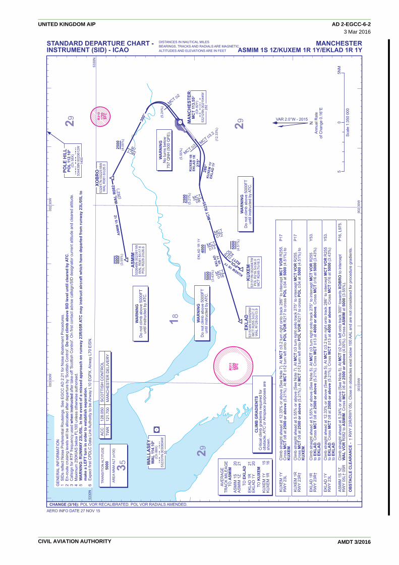
POL 5R Climb straight ahead at 5.55% or above (See Note 5). At MCT D3 turn right onto track 345º towards XUMAT. Cross MCT D7 N57, N601, P18, P17/UP17RWY 23R† at 2500 or above (4.8%). At MCT D8 turn right to intercept POL VOR R220 (040º) to POL VOR. Cross POL D16 at 4000 Northbound and for aircraft or above. Cross POL D9 at 5000. Cross POL VOR at 5000. leaving controlled airspace.
POL 1Y Climb straight ahead at 12.33% or above (See Note 5). At MCT D3.2 turn right onto track 345º towards XUMAT. Cross N57, N601, P18, P17/UP17RWY 23L MCT D7 at 2500 or above (4.8%). At MCT D8 turn right to intercept POL VOR R220 (040º) to POL VOR. Cross POL D16 Northbound and for aircraft at 4000 or above. Cross POL D9 at 5000. Cross POL VOR at 5000. leaving controlled airspace.
POL 4S Climb straight ahead. At not below 757 ALT (500 AAL), but not before DER, adjust track onto MCT VOR R053 (See Note 5). N57, N601, P18, P17/UP17RWY 05L† At MCT D7 turn left to intercept POL VOR R181 (001º) to POL VOR. Cross POL D12 at 4000 or above (4.27%). Cross Northbound and for aircraft POL D8 at 5000. Cross POL VOR at 5000. leaving controlled airspace.
POL 1Z Climb straight ahead on MCT VOR R053 (See Note 5). At MCT D7 turn left to intercept POL VOR R181 (001º) to POL VOR. N57, N601, P18, P17/UP17RWY 05R Cross POL D12 at 4000 or above. Cross POL D8 at 5000. Cross POL VOR at 5000. Northbound and for aircraft leaving controlled airspace.
OBSTACLE CLEARANCE - † RWY 23R/RWY 05L: Close in obstacles exist below 100 AAL and are not considered for procedure gradients.
GENERAL INFORMATION1 SIDs reflect Noise Preferential Routeings. See EGCC AD 2.21 for Noise Abatement Procedures.2 En-route cruising levels will be allocated after departure by 'Scottish Control'. Do not climb above SID level until cleared by ATC..3 Callsign for RTF frequency used when instructed after take-off 'Scottish Control'. On first contact advise callsign/SID designator current altitude and cleared altitude.4 Maximum 250KIAS below FL100 unless otherwise authorised.5 WARNING: RUNWAY 23L/05L. In the event of a missed approach on runway 23R/05R ATC may instruct aircraft which have departed from runway 23L/05L to make a LEFT turn in order to establish separation.6 Expect first CPDLC Data Link Authority to be EGPX.
CLIMB GRADIENTSCritical climb gradients required for obstacle, ATC or Airspace purposes are shown.
AVERAGETRACK MILEAGE
TO POL VOR POL 5R 34 POL 4S 25 POL 1Y 34 POL 1Z 26
ACC 136.575 SCOTTISH CONTROLTWR 121.700 MANCHESTER DELIVERY
WARNINGDo not climb above 5000FT
until instructed by ATC.
WARNINGNo turns below
757 QNH (500 QFE).
TRANSITION ALTITUDE5000
AREA MNM ALT (x100)
31
29
29
18
35
31
35
5000
5000
5000
4000(4.27%)
4000
2500(4.8%)
Scale 1:350 000
5 0 5NM
AERO INFO DATE 27 NOV 15
MANCHESTERPOL 5R 4S 1Y 1Z
CHANGE (3/16): MAG VAR. POL VOR RECALIBRATED. POL VOR RADIALS AMENDED.
STANDARD DEPARTURE CHART -INSTRUMENT (SID) - ICAO
DISTANCES IN NAUTICAL MILESBEARINGS, TRACKS AND RADIALS ARE MAGNETICALTITUDES AND ELEVATIONS ARE IN FEET
UNITED KINGDOM AIP AD 2-EGCC-6-53 Mar 2016
CIVIL AVIATION AUTHORITY AMDT 3/2016

D3142900SFC
D3043500SFC
R3191700SFC
MANCHESTERMCT 113.55D
(Ch 82Y) mct
532125N 0021544W282
(5.55%)
(12.33%)
MCTD3
MCTD3.2
DESIG533138N 0015334WWAL R081.6/D45.3POL R151.2/D15.0
SONEX532953N 0021021WWAL R081.6/D35.1POL R190.8/D15.0
MCTMCTD1212MCTD12
MCTMCTD1414MCTD14
WAL
WAL
D3333W
ALD33
MCTD7
MCTD8
MCT R053
345°
WAL R082SONEX 1R 1Y
DESIG 1S 1Z
XUMAT532757N 0022823WWAL R081.6/D24.1POL R219.8/D21.3
POLE HILLPOL 112.10D
(Ch 58X) pol
534438N 0020612W1400
WALLASEYWAL 114.10D
(Ch 88X) wal
532331N 0030804W55
2500(4.8%)
50005000
5000
4000(5.7%)
5330N 5330N
002 30W 002 00W
NAnnual RateAnnual Rate
of Change 0.16°Eof Change 0.16°E
NAnnual Rate
of Change 0.16°E
VAR
2.9°W - 2009
VAR
2.9°W - 2009
VAR
2.0°W - 2015
CLIMB GRADIENTSCritical climb gradients required for obstacle ATC or Airspace purposes are shown.
SONEX 1R Climb straight ahead at 5.55% or above (See Note 5). At MCT D3 turn right onto track 345° towards XUMAT. Cross MCT D7 L975.RWY 23R† at 2500 or above (4.8%). At MCT D8 turn right onto WAL VOR R082 to SONEX. Cross WAL D33 at 5000. Cross SONEX at 5000.
SONEX 1Y Climb straight ahead at 12.33% or above (See Note 5). At MCT D3.2 turn right onto track 345° towards XUMAT. Cross L975.RWY 23L MCT D7 at 2500 or above (4.8%). At MCT D8 turn right onto WAL VOR R082 to SONEX. Cross WAL D33 at 5000. Cross SONEX at 5000.
DESIG 1S Climb straight ahead. At not below 757 ALT (500 AAL), but not before DER, adjust track onto MCT VOR R053 (See Note 5). L975, L603, L26, Y70.RWY 05L† Cross MCT D12 at 4000 or above (5.7%). At MCT D14 turn right to intercept WAL VOR R082 to DESIG. Cross DESIG at 5000. DESIG 1Z Climb straight ahead on MCT VOR R053 (See Note 5). Cross MCT D12 at 4000 or above (5.7%). At MCT D14 turn right to L975, L603, L26, Y70.RWY 05R intercept WAL VOR R082 to DESIG. Cross DESIG at 5000.
OBSTACLE CLEARANCE - † RWY 23R/RWY 05L: Close in obstacles exist below 100 AAL and are not considered for procedure gradients.
GENERAL INFORMATION1 SIDs reflect Noise Preferential Routeings. See EGCC AD 2.21 for Noise Abatement Procedures.2 En-route cruising levels will be allocated after departure by 'Scottish Control'. Do not climb above SID level until cleared by ATC.3 Callsign for RTF frequency used when instructed after take-off 'Scottish Control'. On first contact advise callsign/SID designator current altitude and cleared altitude.4 Maximum 250KIAS below FL100 unless otherwise authorised.5 WARNING: RUNWAY 23L/05L. In the event of a missed approach on runway 23R/05R ATC may instruct aircraft which have departed from runway 23L/05L to make a LEFT turn in order to establish separation.6 Expect first CPDLC Data Link Authority to be EGTT.
AVERAGETRACK MILEAGE
TO SONEX SONEX 1R 21 SONEX 1Y 21
TO DESIG DESIG 1S 17 DESIG 1Z 16
ACC 136.575 SCOTTISH CONTROLTWR 121.700 MANCHESTER DELIVERY
WARNINGDo not climb above 5000FT
until instructed by ATC.
WARNINGNo turns below
757 QNH (500 QFE).
TRANSITION ALTITUDE5000
AREA MNM ALT (x100)
31
29
29
18
35
31
35
Scale 1:350 000
5 0 5NM
AERO INFO DATE 27 NOV 15
MANCHESTERSONEX 1R 1Y/DESIG 1S 1Z
CHANGE (3/16): MAG VAR. POL VOR RECALIBRATED. POL VOR RADIALS AMENDED.
STANDARD DEPARTURE CHART -INSTRUMENT (SID) - ICAO
DISTANCES IN NAUTICAL MILESBEARINGS, TRACKS AND RADIALS ARE MAGNETICALTITUDES AND ELEVATIONS ARE IN FEET
UNITED KINGDOM AIP AD 2-EGCC-6-63 Mar 2016
CIVIL AVIATION AUTHORITY AMDT 3/2016
D3043500SFC
R3191700SFC
TABLY531619N 0022702WHON R334.6/D62.0
SANBA530822N 0022003WHON R334.6/D53.0
MANCHESTERMCT 113.55D
(Ch 82Y) mct
532125N 0021544W282
MCT D3MCT D3.2
HOND58
MC
TD
5
MC
TD
5
9
HON R335
(155°)
(5.55%)
(12.33%)
275°
285°
HONILEYHON 113.65D
(Ch 83Y) hon
522124N 0013949W435
NAnnual RateAnnual Rate
of Change 0.16°Eof Change 0.16°E
NAnnual Rate
of Change 0.16°E
VAR
2.0°W - 2015
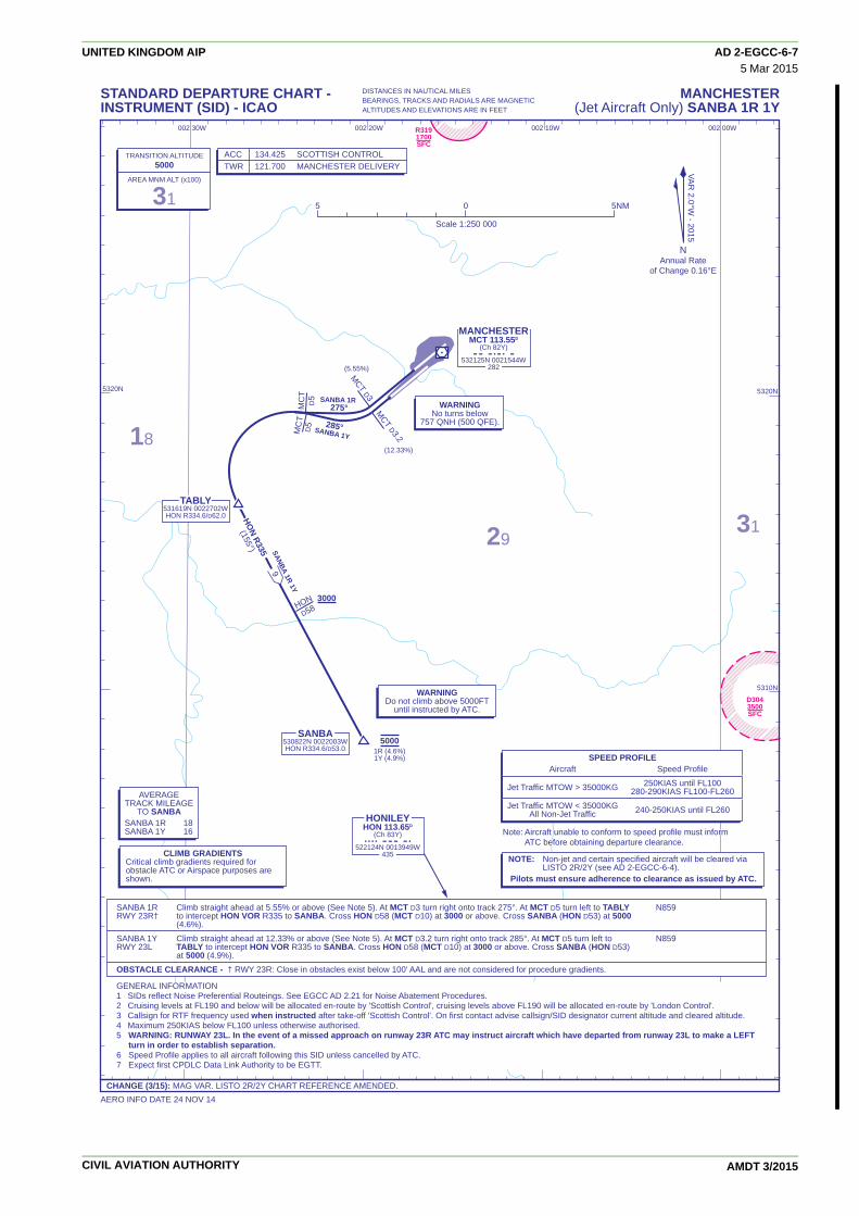
SANBA 1R Climb straight ahead at 5.55% or above (See Note 5). At MCT D3 turn right onto track 275°. At MCT D5 turn left to TABLY N859RWY 23R† to intercept HON VOR R335 to SANBA. Cross HON D58 (MCT D10) at 3000 or above. Cross SANBA (HON D53) at 5000 (4.6%).
SANBA 1Y Climb straight ahead at 12.33% or above (See Note 5). At MCT D3.2 turn right onto track 285°. At MCT D5 turn left to N859RWY 23L TABLY to intercept HON VOR R335 to SANBA. Cross HON D58 (MCT D10) at 3000 or above. Cross SANBA (HON D53) at 5000 (4.9%).
OBSTACLE CLEARANCE - † RWY 23R: Close in obstacles exist below 100' AAL and are not considered for procedure gradients.
GENERAL INFORMATION1 SIDs reflect Noise Preferential Routeings. See EGCC AD 2.21 for Noise Abatement Procedures.2 Cruising levels at FL190 and below will be allocated en-route by 'Scottish Control', cruising levels above FL190 will be allocated en-route by 'London Control'.3 Callsign for RTF frequency used when instructed after take-off 'Scottish Control'. On first contact advise callsign/SID designator current altitude and cleared altitude.4 Maximum 250KIAS below FL100 unless otherwise authorised.5 WARNING: RUNWAY 23L. In the event of a missed approach on runway 23R ATC may instruct aircraft which have departed from runway 23L to make a LEFT turn in order to establish separation.6 Speed Profile applies to all aircraft following this SID unless cancelled by ATC.7 Expect first CPDLC Data Link Authority to be EGTT.
SPEED PROFILE Aircraft Speed Profile
Jet Traffic MTOW > 35000KG 250KIAS until FL100 280-290KIAS FL100-FL260
Jet Traffic MTOW < 35000KG 240-250KIAS until FL260 All Non-Jet Traffic
NOTE: Non-jet and certain specified aircraft will be cleared via LISTO 2R/2Y (see AD 2-EGCC-6-4).Pilots must ensure adherence to clearance as issued by ATC.
CLIMB GRADIENTSCritical climb gradients required for obstacle ATC or Airspace purposes are shown.
AVERAGETRACK MILEAGE
TO SANBA SANBA 1R 18 SANBA 1Y 16
ACC 134.425 SCOTTISH CONTROLTWR 121.700 MANCHESTER DELIVERY
Note: Aircraft unable to conform to speed profile must inform Note: Aircraft unable to conform to speed profile must inform ATC before obtaining departure clearance. ATC before obtaining departure clearance.Note: Aircraft unable to conform to speed profile must inform ATC before obtaining departure clearance.
WARNINGDo not climb above 5000FT
until instructed by ATC.
TRANSITION ALTITUDE5000
AREA MNM ALT (x100)
31
WARNINGNo turns below
757 QNH (500 QFE).
5320N 5320N
5310N
002 00W002 10W002 20W002 30W
2931
18
5 0 5NM
Scale 1:250 000
50001R (4.6%)1Y (4.9%)
3000SANBA 1R 1Y
SANBA 1R
SANBA 1Y
AERO INFO DATE 24 NOV 14
MANCHESTER(Jet Aircraft Only) SANBA 1R 1Y
CHANGE (3/15): MAG VAR. LISTO 2R/2Y CHART REFERENCE AMENDED.
STANDARD DEPARTURE CHART -INSTRUMENT (SID) - ICAO
DISTANCES IN NAUTICAL MILESBEARINGS, TRACKS AND RADIALS ARE MAGNETICALTITUDES AND ELEVATIONS ARE IN FEET
UNITED KINGDOM AIP AD 2-EGCC-6-75 Mar 2015
CIVIL AVIATION AUTHORITY AMDT 3/2015

R4132200SFC
D4093400SFC
D4423000SFC
D4412400SFC
D314D31429002900SFCSFC
D3142900SFC
D3043500SFC
R4322200SFC
R5012400SFC
R4452000SFC
R4442000SFC
R3122100SFC
R3211600SFC
R3191700SFC
R3112200SFC
D405A1000SFC
D40650000
(OCNL 80000)SFC
D40515000
(OCNL 50000)SFC
D5105500
(OCNL 18000)SFC
D40710000
(OCNL 13500)SFC
D4083000
(OCNL 5600)SFC
D406B50000
(OCNL 80000)SFC
353°
234°
237°
173°
FL70
LAKEY541420N 0025852WTNT R328.8/D85.2
ROSUN 2A
41
TNT R329
(149°)
MC
T R353
(173°)
POL
R01
1PO
L R
011
(191
°)(1
91°)
POL
R01
1(1
91°)
TRENTTNT 115.70D
(Ch 104X) tnt
530314N 0014012W968
✧ ✧ ✧ ✧
✧ ✧ ✧ ✧SLP
SLPTNT D56MCT D31
MANCHESTERMCT 113.55D
(Ch 82Y) mct
532125N 0021544W282
ROSUN534008N 0022057WMCT R352.7/D19.0TNT R328.4/D44.3
RO
SUN
2B 4D
21
POLE HILLPOL 112.10D
(Ch 58X) pol
534438N 0020612W1400
GASKO541329N 0015721WPOL R011.5/D29.4
TILNI543251N 0015118WPOL R011.5/D49.1
SETEL540045N 0022609WMCT R353.2/D39.9
BEGAM540925N 0020715WMCT R008.0/D48.3
RO
SUN
4D
20
ROSUN 4D
14
7
ROSUN 4D
ROSUN 2A Arrival via L612 at FL150 and above to LAKEY. At LAKEY turn left onto TNT VOR R329 to ROSUN. FL200 by 10NM before LAKEY
ROSUN 2B Arrival via N57 at FL140 and below to SETEL. At SETEL turn right onto MCT VOR R353 to ROSUN.
ROSUN 4D Arrival via P18/UP18 to TILNI, continue on POL VOR R011 to GASKO. At GASKO turn right onto track 237° to BEGAM. FL230 by TILNI At BEGAM turn left onto track 234° to SETEL. At SETEL turn left onto MCT VOR R353 to ROSUN.
GENERAL INFORMATION1 When MCT VOR is out of service routes will be to DALEY, see AD 2 EGCC-7-2.2 Aircraft joining controlled airspace from the north-east will route via SETEL.3 Standard routes may be varied at the discretion of ATC.4 Cross SLPs or 3 MIN before holding facility at 250KIAS or less when at FL140 or below.
VA
R 2.0°W
- 2015V
AR
2.0°W - 2015
NAnnual RateAnnual Rate
of Change 0.15°Eof Change 0.15°E
NAnnual Rate
of Change 0.16°E
VA
R 2.0°W
- 2015
5430N
5330N
5400N
5430N5430N5430N
5330N
5400N
003 30W003 30W003 30W 003 00W003 00W003 00W 002 30W002 30W002 30W 002 00W002 00W002 00W 001 30W001 30W001 30W
APP 118.575, 135.000* MANCHESTER RADAR 121.350 MANCHESTER DIRECTORTWR 118.625, 119.400 MANCHESTER TOWERATIS 128.175 MANCHESTER INFORMATION* As directed by ATC.
WARNINGDo not exceed 230KIAS at ROSUN.
DESCENT PLANNING -ATC REQUIREMENTS
When determining top of descent point, pilots should anticipate possible descent clearance to the levels shown in the table below and possible descent clearance to the lowest holding level (FL70) by ROSUN. Pilots unable to comply must notify ATC as soon as possible.
ACTUAL DESCENT CLEARANCE WILL BE AS DIRECTED BY ATC.
WARNINGDo not proceed beyond ROSUN without ATC clearance.
WARNINGFor Minimum Descent Rate requirementsSee ENR 1.1 para 3.2
5 0 5 10 15NM
TRANSITION ALTITUDE5000
TRANSITION LEVELATC
AREA MNM ALT (x100)
4529
27
29
29
29
21
42
43
45
4038
39 35 3433
35
31
35
15
17
18
16
14
Scale 1:1 000 000
AERO INFO DATE 27 NOV 15
MANCHESTERvia ROSUN (north)
CHANGE (3/16): POL VOR RECALIBRATED. ROSUN 4D POL VOR RADIALS.
STANDARD ARRIVAL CHART -INSTRUMENT (STAR) - ICAO
DISTANCES IN NAUTICAL MILESBEARINGS, TRACKS AND RADIALS ARE MAGNETICALTITUDES AND ELEVATIONS ARE IN FEET
UNITED KINGDOM AIP AD 2-EGCC-7-13 Mar 2016
CIVIL AVIATION AUTHORITY AMDT 3/2016

D314D31429002900SFCSFC
R4132200SFC
D4093400SFC
D4423000SFC
D4412400SFC
D3142900SFC
D3043500SFC
R4322200SFC
R5012400SFC
R4452000SFC
R4442000SFC
R3122100SFC
R3211600SFC
R3191700SFC
R3112200SFC
D405A1000SFC
D406 50000
(OCNL 80000)SFC
D40515000
(OCNL 50000)SFC
D5105500
(OCNL 18000)SFC
D40710000
(OCNL 13500)SFC
D4083000
(OCNL 5600)SFC
D406B 50000
(OCNL 80000)SFC
329°
234°
237°
149° FL140FL70
LAKEY541420N 0025852WTNT R328.8/D85.2
DALEY 2A
41
TNT R329
(149°)
173°
POL
R01
2PO
L R
012
(191
°)(1
91°)
POL
R01
1(1
91°)
TRENTTNT 115.70D
(Ch 104X) tnt
530314N 0014012W968
✧ ✧ ✧ ✧
✧ ✧ ✧ ✧SLP
SLPTNT D56
DA
LEY2B
4D21
POLE HILLPOL 112.10D
(Ch 58X) pol
534438N 0020612W1400
GASKO541329N 0015721WPOL R011.5/D29.4
TILNI543251N 0015118WPOL R011.5/D49.1
SETEL540045N 0022609W
BEGAM540925N 0020715W
DA
LEY
4D20
DALEY 4D
14
7
DALEY 4D
DALEY534008N 0022057WTNT R328.4/D44.3
TNT
D49
DALEY 2A Arrival via L612 at FL150 and above to LAKEY. At LAKEY turn left onto TNT VOR R329 to DALEY. FL200 by 10NM before LAKEY
DALEY 2B Arrival via N57 at FL140 and below to SETEL. At SETEL turn right onto track 173° to DALEY.
DALEY 4D Arrival via P18/UP18 to TILNI, continue on POL VOR R011 to GASKO. At GASKO turn right onto track 237° to BEGAM. At FL230 by TILNI BEGAM turn left onto track 234° to SETEL. At SETEL turn left onto track 173° to DALEY
GENERAL INFORMATION1 When MCT VOR is operating routes will be to ROSUN, see AD 2 EGCC-7-1.2 Aircraft joining controlled airspace from the north-east will route via SETEL.3 Standard routes may be varied at the discretion of ATC.4 Cross SLPs or 3 MIN before holding facility at 250KIAS or less when at FL140 or below.
VA
R 2.0°W
- 2015V
AR
2.0°W - 2015
NAnnual RateAnnual Rate
of Change 0.15°Eof Change 0.15°E
NAnnual Rate
of Change 0.16°E
VA
R 2.0°W
- 2015
5430N
5330N
5400N
5430N5430N5430N
5330N
5400N
003 30W003 30W003 30W 003 00W003 00W003 00W 002 30W002 30W002 30W 002 00W002 00W002 00W 001 30W001 30W001 30W
APP 118.575, 135.000* MANCHESTER RADAR 121.350 MANCHESTER DIRECTORTWR 118.625, 119.400 MANCHESTER TOWERATIS 128.175 MANCHESTER INFORMATION* As directed by ATC.
WARNINGDo not exceed 230KIAS at DALEY.
DESCENT PLANNING -ATC REQUIREMENTS
When determining top of descent point, pilots should anticipate possible descent clearance to the levels shown in the table below and possible descent clearance to the lowest holding level (FL70) by DALEY. Pilots unable to comply must notify ATC as soon as possible.
ACTUAL DESCENT CLEARANCE WILL BE AS DIRECTED BY ATC.
WARNINGDo not proceed beyond DALEY without ATC clearance.
WARNINGFor Minimum Descent Rate requirementsSee ENR 1.1 para 3.2
5 0 5 10 15NM
TRANSITION ALTITUDE5000
TRANSITION LEVELATC
AREA MNM ALT (x100)
4529
27
29
29
29
21
42
43
45
4038
39 35 3433
35
31
35
15
17
18
16
14
Scale 1:1 000 000
AERO INFO DATE 27 NOV 15
MANCHESTERvia DALEY (north) (MCT VOR u/s)
CHANGE (3/16): POL VOR RECALIBRATED. DALEY 4D POL VOR RADIALS.
STANDARD ARRIVAL CHART -INSTRUMENT (STAR) - ICAO
DISTANCES IN NAUTICAL MILESBEARINGS, TRACKS AND RADIALS ARE MAGNETICALTITUDES AND ELEVATIONS ARE IN FEET
UNITED KINGDOM AIP AD 2-EGCC-7-23 Mar 2016
CIVIL AVIATION AUTHORITY AMDT 3/2016

D20
7D
207
2300
023
000
(Out
side
hou
rs 5
000)
(Out
side
hou
rs 5
000)
SFC
SFC
D20
723
000
(Out
side
hou
rs 5
000)
SFC
D21
1 2
400
SFC
D30
515
00SF
C
R31
195
00SF
C
D30
650
00SF
C
D41
010
00SF
C
R31
520
00SF
C
D30
7D
307
2000
020
000
OC
NL
2300
0O
CN
L 23
000
(Out
side
hou
rs 5
000)
(Out
side
hou
rs 5
000)
SFC
SFC
D30
720
000
OC
NL
2300
0(O
utsi
de h
ours
500
0)SF
C
D44
230
00SF
C
D44
124
00SF
C
D31
429
00SF
C D30
435
00SF
C
R44
4R
444
2000
2000
SFC
SFC
R44
420
00SF
C
R31
221
00SF
C
R32
116
00SF
C
R31
917
00SF
C
R31
122
00SF
C
D32
3B
FL66
0FL
50
D32
3E
FL66
0FL
250 D
308
5000
SFC
353°
POL
R26
8
298°
263°
263°
279°
173°
FL70
TREN
TTN
T 11
5.70
D
(Ch
104X
) tn
t
5303
14N
001
4012
W96
8
✧ ✧ ✧ ✧
SLP
MA
NC
HES
TER
MC
T 11
3.55
D
(Ch
82Y
) m
ct
5321
25N
002
1544
W28
2
RO
SUN
5340
08N
002
2057
WM
CT
R35
2.7/
D19
.0TN
T R
328.
4/D
44.3PO
LE H
ILL
POL
112.
10D
(Ch
58X
) p
ol
5344
38N
002
0612
W14
00
RO
SUN
1G
42
RO
SUN
1F
1G37
RO
SUN
2E 1
F 1G
15
ROSU
N 1F
44
RO
SUN
2E
21
ROSUN 2E
ROSUN 2E
1515ROSUN 2E
15
8R
OSU
N 2
E
LIB
SO53
3129
N 0
0005
36E O
TBED
5317
17N
000
0155
E
GO
LES
5336
29N
001
0500
WP
OL
R10
3.5/
D37
.3
UPT
ON
5335
13N
001
1803
WP
OL
R10
9.2/
D30
.2
BU
RN
I53
4338
N 0
0231
04W
PO
L R
267.
6/D
14.8
MC
T R
339.
9/D
24.0
DES
IG53
3138
N 0
0153
34W
PO
L R
151.
2/D
15.0
POL R151
(331°)
POL
R10
4(2
84°)
002
00W
001
00W
RO
SU
N 2
E
Arr
ival
via
L97
5 ea
st a
t FL8
0 to
GO
LES,
con
tinue
on
track
263
° to
UPT
ON
then
DES
IG. A
t DES
IG
turn
righ
t ont
o PO
L VO
R R
151
to P
OL
VOR
. At P
OL
VOR
turn
left
onto
PO
L VO
R R
268
to B
UR
NI.
A
t BU
RN
I tur
n rig
ht to
inte
rcep
t MC
T VO
R R
353
to R
OSU
N.
RO
SU
N 1
F A
rriv
al v
ia Y
70/U
Y70
to O
TBED
, con
tinue
on
track
298
° to
GO
LES.
At G
OLE
S tu
rn le
ft on
to
FL29
0 le
vel O
TBED
PO
L VO
R R
104
to P
OL
VOR
. At P
OL
VOR
turn
left
onto
PO
L VO
R R
268
to B
UR
NI.
At B
UR
NI t
urn
FL17
0 le
vel G
OLE
S
right
to in
terc
ept M
CT
VOR
R35
3 to
RO
SUN
.
RO
SU
N 1
G
Arr
ival
via
UL9
75 e
ast t
o LI
BSO
, con
tinue
on
track
279
° to
GO
LES.
At G
OLE
S tu
rn ri
ght o
nto
FL20
0 by
GO
LES
PO
L VO
R R
104
to P
OL
VOR
. At P
OL
VOR
turn
left
onto
PO
L VO
R R
268
to B
UR
NI.
At B
UR
NI t
urn
rig
ht to
inte
rcep
t MC
T VO
R R
353
to R
OSU
N.
NA
nnua
l Rat
eof
Cha
nge
0.16
°E
GE
NE
RA
L IN
FOR
MA
TIO
N1
Whe
n M
CT
VOR
is o
ut o
f ser
vice
rout
es w
ill b
e to
DA
LEY,
see
AD
2 E
GC
C-7
-4.
2 A
ircra
ft jo
inin
g co
ntro
lled
airs
pace
from
the
north
-eas
t will
rout
e vi
a SE
TEL.
3 S
tand
ard
rout
es m
ay b
e va
ried
at th
e di
scre
tion
of A
TC.
4 C
ross
SLP
s or
3 M
IN b
efor
e ho
ldin
g fa
cilit
y at
250
KIA
S o
r les
s w
hen
at F
L140
or b
elow
.
VAR 2.0°W - 2015
5330
N53
30N
5330
N
5400
N54
00N
5400
N
5300
N53
00N
5300
N53
00N
5300
N53
00N
5330
N53
30N
5330
N5400
N
003
00W
002
30W
001
30W
000
30W
000
30W
000
30W
000
0000
0 30
E
AP
P
118.
575,
135
.000
*
MA
NC
HE
STE
R R
AD
AR
12
1.35
0 M
AN
CH
ES
TER
DIR
EC
TOR
TWR
11
8.62
5, 1
19.4
00
MA
NC
HE
STE
R T
OW
ER
ATI
S
128.
175
M
AN
CH
ES
TER
INFO
RM
ATI
ON
* A
s di
rect
ed b
y A
TC.
WA
RN
ING
Do
not e
xcee
d 23
0KIA
S a
t RO
SUN
.
DES
CEN
T PL
AN
NIN
G -
ATC
REQ
UIR
EMEN
TSW
hen
dete
rmin
ing
top
of d
esce
nt p
oint
, pi
lots
sho
uld
antic
ipat
e po
ssib
le d
esce
nt
clea
ranc
e to
the
leve
ls s
how
n in
the
tabl
e ab
ove
and
poss
ible
des
cent
cle
aran
ce to
th
e lo
wes
t hol
ding
leve
l (FL
70) b
y R
OSU
N. P
ilots
una
ble
to c
ompl
y m
ust
notif
y AT
C a
s so
on a
s po
ssib
le.
AC
TUA
L D
ESC
ENT
CLE
AR
AN
CE
WIL
L B
E A
S D
IREC
TED
BY
ATC
.
WA
RN
ING
Do
not p
roce
ed b
eyon
d R
OSU
N w
ithou
t A
TC c
lear
ance
. WA
RN
ING
For M
inim
um D
esce
nt R
ate
requ
irem
ents
See
EN
R 1
.1 p
ara
3.2
50
510
15N
M
TRA
NS
ITIO
N A
LTIT
UD
E50
00TR
AN
SIT
ION
LE
VE
LAT
CA
RE
A M
NM
ALT
(x10
0)
39
15
1414
1418
25
21
31
35
35
39
35
33
34
2026
2929
271519
17
18
25
Sca
le 1
:1 0
00 0
00
MANCHESTERvia ROSUN (east)
AERO INFO DATE 27 NOV 15CHANGE (3/16): POL VOR RECALIBRATED. POL VOR RADIALS.
STANDARD ARRIVAL CHART -INSTRUMENT (STAR) - ICAO
DISTANCES IN NAUTICAL MILESBEARINGS, TRACKS AND RADIALS ARE MAGNETICALTITUDES AND ELEVATIONS ARE IN FEET
UNITED KINGDOM AIP AD 2-EGCC-7-33 Mar 2016
CIVIL AVIATION AUTHORITY AMDT 3/2016

D20
7D
207
2300
023
000
(Out
side
hou
rs 5
000)
(Out
side
hou
rs 5
000)
SFC
SFC
D20
723
000
(Out
side
hou
rs 5
000)
SFC
D21
1 2
400
SFC
D30
515
00SF
C
R31
195
00SF
C
D30
650
00SF
C
D41
010
00SF
C
R31
520
00SF
C
D30
7D
307
2000
020
000
OC
NL
2300
0O
CN
L 23
000
(Out
side
hou
rs 5
000)
(Out
side
hou
rs 5
000)
SFC
SFC
D30
720
000
OC
NL
2300
0(O
utsi
de h
ours
500
0)SF
C
D44
230
00SF
C
D44
124
00SF
C
D31
429
00SF
C D30
435
00SF
C
R44
420
00SF
C
R31
221
00SF
C
R32
116
00SF
C
R31
917
00SF
C
R31
122
00SF
C
D30
850
00SF
C
D32
3B
FL66
0FL
50
D32
3E
FL66
0FL
250
POL
R291
298°
263°
263°
279°
TREN
TTN
T 11
5.70
D
(Ch
104X
) tn
t
5303
14N
001
4012
W96
8
✧ ✧ ✧ ✧
SLP
POLE
HIL
LPO
L 11
2.10
D
(Ch
58X
) p
ol
5344
38N
002
0612
W14
00
DA
LEY
1G42
DA
LEY
1F 1
G37
DALE
Y2E
1F
1G7
DALE
Y 1F
44
DA
LEY
2E
21
8D
ALE
Y 2E
LIB
SO53
3129
N 0
0005
36E O
TBED
5317
17N
000
0155
E
GO
LES
5336
29N
001
0500
WP
OL
R10
3.5/
D37
.3
UPT
ON
5335
13N
001
1803
WP
OL
R10
9.2/
D30
.2D
ESIG
5331
38N
001
5334
WP
OL
R15
1.2/
D15
.0
POL R151
(331°)
POL
R10
4(2
84°)
328°
148°
FL14
0FL
70D
ALE
Y53
4008
N 0
0220
57W
TNT
R32
8.4/
D44
.3TNT D4
9
TNT R328
AR
THA
5346
59N
002
1707
WP
OL
R29
1.4/
D6.
9
DALEYDALEY 2E 2E
1515DALEY 2E
15002
00W
001
00W
DA
LEY
2E
A
rriv
al v
ia L
975
east
at F
L80
to G
OLE
S, c
ontin
ue o
n tra
ck 2
63°
to U
PTO
N th
en D
ESIG
. At D
ESIG
tu
rn ri
ght o
nto
POL
VOR
R15
1 to
PO
L VO
R. A
t PO
L VO
R tu
rn le
ft on
to P
OL
VOR
R29
1 to
AR
THA
.
At A
RTH
A tu
rn le
ft to
inte
rcep
t TN
T VO
R R
328
to D
ALE
Y.
DA
LEY
1F
Arr
ival
via
Y70
/UY
70 to
OTB
ED, c
ontin
ue o
n tra
ck 2
98°
to G
OLE
S. A
t GO
LES
turn
left
onto
FL
280
leve
l OTB
ED
POL
VOR
R10
4 to
PO
L VO
R. A
t PO
L VO
R tu
rn ri
ght o
nto
POL
VOR
R29
1 to
AR
THA
. FL
170
leve
l GO
LES
A
t AR
THA
turn
left
to in
terc
ept T
NT
VOR
R32
8 to
DA
LEY.
DA
LEY
1G
A
rriv
al v
ia U
L975
eas
t to
LIB
SO, c
ontin
ue o
n tra
ck 2
79°
to G
OLE
S. A
t GO
LES
turn
righ
t ont
o FL
200
by G
OLE
S
POL
VOR
R10
4 to
PO
L VO
R. A
t PO
L VO
R tu
rn ri
ght o
nto
POL
VOR
R29
1 to
AR
THA
.
At A
RTH
A tu
rn le
ft to
inte
rcep
t TN
T VO
R R
328
to D
ALE
Y.
NA
nnua
l Rat
eof
Cha
nge
0.16
°E
GE
NE
RA
L IN
FOR
MA
TIO
N1
Whe
n M
CT
VOR
is o
pera
ting
rout
es w
ill b
e to
RO
SUN
, see
AD
2 E
GC
C-7
-3.
2 S
tand
ard
rout
es m
ay b
e va
ried
at th
e di
scre
tion
of A
TC.
3 C
ross
SLP
s or
3 M
IN b
efor
e ho
ldin
g fa
cilit
y at
250
KIA
S o
r les
s w
hen
at F
L140
or b
elow
.
VAR 2.0°W - 2015
5330
N53
30N
5330
N
5454 00N
00N
5400
N54
00N
5400
N
5300
N53
00N
5300
N53
00N
5300
N53
00N
5330
N53
30N
5330
N5400
N
003
00W
002
30W
001
30W
000
30W
000
30W
000
30W
000
0000
0 30
E
AP
P
118.
575,
135
.000
*
MA
NC
HE
STE
R R
AD
AR
12
1.35
0 M
AN
CH
ES
TER
DIR
EC
TOR
TWR
11
8.62
5, 1
19.4
00
MA
NC
HE
STE
R T
OW
ER
ATI
S
128.
175
M
AN
CH
ES
TER
INFO
RM
ATI
ON
* A
s di
rect
ed b
y A
TC.
WA
RN
ING
Do
not e
xcee
d 23
0KIA
S a
t DA
LEY.
WA
RN
ING
Do
not p
roce
ed b
eyon
d D
ALE
Y w
ithou
t A
TC c
lear
ance
. WA
RN
ING
For M
inim
um D
esce
nt R
ate
requ
irem
ents
See
EN
R 1
.1 p
ara
3.2
50
510
15N
M
TRA
NS
ITIO
N A
LTIT
UD
E50
00TR
AN
SIT
ION
LE
VE
LAT
CA
RE
A M
NM
ALT
(x10
0)
39
15
1414
1418
25
21
31
35
35
39
35
33
34
2026
2929
271519
17
18
25
Sca
le 1
:1 0
00 0
00
DES
CEN
T PL
AN
NIN
G -
ATC
REQ
UIR
EMEN
TSW
hen
dete
rmin
ing
top
of d
esce
nt p
oint
, pi
lots
sho
uld
antic
ipat
e po
ssib
le d
esce
nt
clea
ranc
e to
the
leve
ls s
how
n in
the
tabl
e be
low
and
pos
sibl
e de
scen
t cle
aran
ce to
th
e lo
wes
t hol
ding
leve
l (FL
70) b
y D
ALE
Y. P
ilots
una
ble
to c
ompl
y m
ust
notif
y AT
C a
s so
on a
s po
ssib
le.
AC
TUA
L D
ESC
ENT
CLE
AR
AN
CE
WIL
L B
E A
S D
IREC
TED
BY
ATC
.
MANCHESTERvia DALEY (east) (MCT VOR u/s)
AERO INFO DATE 27 NOV 15CHANGE (3/16): POL VOR RECALIBRATED. POL VOR RADIALS.
STANDARD ARRIVAL CHART -INSTRUMENT (STAR) - ICAO
DISTANCES IN NAUTICAL MILESBEARINGS, TRACKS AND RADIALS ARE MAGNETICALTITUDES AND ELEVATIONS ARE IN FEET
UNITED KINGDOM AIP AD 2-EGCC-7-43 Mar 2016
CIVIL AVIATION AUTHORITY AMDT 3/2016
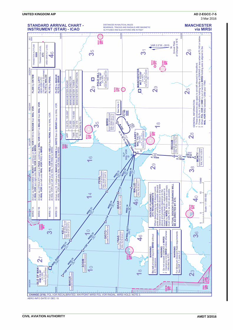
D21
1 2
400
SFC
D31
429
00SF
C
D44
124
00SF
C
D30
435
00SF
C
R44
520
00SF
C
R44
420
00SF
C
R31
221
00SF
C
R32
116
00SF
C
R31
917
00SF
C
R31
122
00SF
C
R21
827
00SF
C
D40
6 5
0000
(OC
NL
8000
0)SF
C
D40
6B 5
0000
(OC
NL
8000
0)SF
C
D40
6C 5
0000
SFC
R32
221
00SF
C
D20
1CD
201C
UN
L U
NL
FL14
5FL
145
D20
1C
UN
LFL
145
D20
1BD
201B
U
NL
UN
LSF
CSF
C
D20
1B
UN
LSF
C
D20
1
UN
LSF
C
WA
LLA
SEY
WA
L 11
4.10
D
(Ch
88X
) w
al
5323
31N
003
0804
W55
'
MA
NC
HES
TER
MC
T 11
3.55
D
(Ch
82Y
) m
ct
5321
25N
002
1544
W28
2
242°
WAL
R06
2
062°
FL14
060
00M
IRSI
1A
1B 1
C
MIR
SI 1
A 1B
1C
1818M
IRSI
1A
1B 1
C 1D
17
MIRSI 1A20
MIR
SI 1
B26
MIR
SI 1
B17
MIRSI
1C31
MIRSI
1C17
MIRSI
1D16
MIRSI
1D18
MIR
SI 1
D16
MIR
SI 1
D22
MIRSI
1C23
MIRSI 1A MIRSI 1A1010
MIRSI 1A10
✧ ✧ ✧ ✧
SLP
WA
L V
OR
POLE
HIL
LPO
L 11
2.10
D
(Ch
58X
) p
ol
5344
38N
002
0612
W14
00
POLD30M
IRSI
5332
17N
002
4242
WW
AL
R06
2.2/
D17
.5P
OL
R24
1.9/
D25
.0
PEN
IL53
3657
N 0
0339
49W
WA
L R
308.
0/D
23.3
IOM
R12
7.2/
D47
.6
KEL
LY53
5419
N 0
0421
51W
WA
L R
308.
0/D
53.7
IOM
R12
7.2/
D17
.2
REX
AM
5304
00N
003
0937
WW
AL
R18
5.1/
D19
.6
MO
NTY
5253
34N
003
1026
WW
AL
R18
5.1/
D30
.0
WALR185(005°)
ISLE
OF
MA
NIO
M 1
12.2
0D
(Ch
59X
) io
m
5404
01N
004
4549
W57
3
ISLE
OF
MA
NIO
M 1
12.2
0D
(Ch
59X
) io
m
5404
01N
004
4549
W57
3
LYN
AS
5326
33N
004
2000
WW
AL
R27
6.9/
D43
.1
MA
LUD
5324
48N
003
3630
WW
AL
R27
6.9/
D17
.1
WA
L R
277
(097
°)
128°
129°
114°
115°
WAL
R308
(128
°)
GIG
TO53
3801
N 0
0405
51W
IBR
AR
5331
54N
003
4111
W
MA
KU
X53
5830
N 0
0452
28W
SOSI
M53
4856
N 0
0430
30W
002
00W
001
30W
NA
nnua
l Rat
eof
Cha
nge
0.16
°E
GE
NE
RA
L IN
FOR
MA
TIO
N1
Thes
e pr
oced
ures
als
o ap
ply
to a
ircra
ft in
boun
d to
Woo
dfor
d.2
Cro
ss S
LPs
or 3
MIN
bef
ore
hold
ing
faci
lity
at 2
50K
IAS
or l
ess
whe
n at
FL1
40 o
r bel
ow.
3 W
hen
POL
VOR
or D
ME
is o
ut o
f ser
vice
MIR
SI h
oldi
ng a
xis
is a
ligne
d to
the
W
AL
VOR
R06
2 be
twee
n 12
NM
and
17N
M.
VAR 2.0°W - 2015
5330
N53
30N
5330
N
5400
N
5300
N53
00N
5300
N
5300
N53
00N
5300
N
5330
N53
30N
5330
N
5400
N54
00N
5400
N
003
00W
003
00W
003
00W
004
00W
004
00W
004
00W
005
00W
002
30W
003
30W
003
30W
003
30W
004
30W
WA
RN
ING
1 D
o no
t exc
eed
230K
IAS
at M
IRSI
.2
Cle
aran
ce li
mit
MIR
SI u
nles
s ot
herw
ise
intru
cted
by
ATC
.
DES
CEN
T PL
AN
NIN
G -
ATC
REQ
UIR
EMEN
TSW
hen
dete
rmin
ing
top
of d
esce
nt p
oint
, pi
lots
sho
uld
antic
ipat
e po
ssib
le d
esce
nt
clea
ranc
e to
the
leve
ls s
how
n in
the
tabl
e ab
ove
and
poss
ible
cle
aran
ce to
the
low
est h
oldi
ng le
vel (
FL e
quiv
alen
t to
6000
) by
MIR
SI. P
ilots
una
ble
to c
ompl
y m
ust n
otify
ATC
as
soon
as
poss
ible
.
AC
TUA
L D
ESC
ENT
CLE
AR
AN
CE
WIL
L B
E A
S D
IREC
TED
BY
ATC
.
WA
RN
ING
Do
not p
roce
ed b
eyon
d M
IRSI
with
out
ATC
cle
aran
ce. W
AR
NIN
GFo
r Min
imum
Des
cent
Rat
e re
quire
men
tsS
ee E
NR
1.1
par
a 3.
2
50
510
15N
M
See
Not
e 3
TRA
NS
ITIO
N A
LTIT
UD
E50
00TR
AN
SIT
ION
LE
VE
LAT
CA
RE
A M
NM
ALT
(x10
0)
46 35
31
31
3529
2823
29
2625
27
29
4546
40
16
18
18
3836
1410
10
Sca
le 1
:1 0
00 0
00
AP
P
118.
575,
135
.000
*
MA
NC
HE
STE
R R
AD
AR
12
1.35
0 M
AN
CH
ES
TER
DIR
EC
TOR
TWR
11
8.62
5, 1
19.4
00
MA
NC
HE
STE
R T
OW
ER
ATI
S
128.
175
M
AN
CH
ES
TER
INFO
RM
ATI
ON
* A
s di
rect
ed b
y A
TC.
4315
MIR
SI 1
A
Arr
ival
via
N86
4/U
N86
4 to
MO
NTY
, con
tinue
on
WA
L VO
R R
185
to R
EXA
M th
en W
AL
VOR
. FL
200
by O
KTE
M
At W
AL
VOR
turn
righ
t ont
o W
AL
VOR
R06
2 to
MIR
SI.
MIR
SI 1
B
Arr
ival
via
L97
5/U
L975
wes
t to
LYN
AS,
con
tinue
on
WA
L VO
R R
277
to M
ALU
D th
en W
AL
VOR
. FL
270
by L
IFFY
A
t WA
L VO
R tu
rn le
ft on
to W
AL
VOR
R06
2 to
MIR
SI
0630
-230
0 U
TC
(1
hr e
arlie
r in
Sum
mer
)
FL
170
by M
ALU
DM
IRS
I 1C
A
rriv
al v
ia L
10. C
ontin
ue o
n W
AL
VOR
R30
8 to
KEL
LY th
en P
ENIL
then
to W
AL
VO
R.
FL17
0 by
PEN
IL
At W
AL
VO
R tu
rn le
ft on
to W
AL
VO
R R
062
to M
IRS
I.
MIR
SI 1
D
Arr
ival
via
L15
. Con
tinue
to M
AK
UX
then
SO
SIM
then
GIG
TO th
en to
IBR
AR
then
to W
AL
VO
R.
FL27
0 by
MA
KU
X
At W
AL
VO
R tu
rn le
ft on
to W
AL
VO
R R
062
to M
IRS
I. FL
170
by IB
RA
R
AERO INFO DATE 01 DEC 15
MANCHESTERvia MIRSI
CHANGE (3/16): POL VOR RECALIBRATED. WAYPOINT MIRSI POL VOR RADIAL. MIRSI HOLD. NOTE 3.
STANDARD ARRIVAL CHART -INSTRUMENT (STAR) - ICAO
DISTANCES IN NAUTICAL MILESBEARINGS, TRACKS AND RADIALS ARE MAGNETICALTITUDES AND ELEVATIONS ARE IN FEET
UNITED KINGDOM AIP AD 2-EGCC-7-53 Mar 2016
CIVIL AVIATION AUTHORITY AMDT 3/2016

D31
429
00SF
C
D30
435
00SF
C
D21
1
2400
SFC
312°132°
FL70
TREN
TTN
T 11
5.70
D
(Ch
104X
) tn
t
5303
14N
001
4012
W96
8
✧ ✧
✧ ✧
SLP
TNT
D5
MA
NC
HES
TER
MC
T 11
3.55
D
(Ch
82Y
) m
ct
5321
25N
002
1544
W28
2
DAYNE 1B29
DAYNE 2A 1B
17
TNT R
132
(312
°)
TNT R
312
DA
YNE
5314
19N
002
0145
WTN
T R
312.
3/D
17.1
MC
T R
132.
3/D
11.0
AM
LET
5316
07N
001
5018
WM
CT
R11
1.2/
D16
.2TN
T R
336.
4/D
14.3
LEST
A52
4427
N 0
0104
19W
TNT
R13
2.3/
D28
.7
002
00W
001
00W
DA
YN
E 2
A
Arr
ival
via
N57
/T42
0/U
T420
/Q4
to T
NT
VOR
, con
tinue
on
TNT
VOR
R31
2 to
DA
YNE.
FL
200
by 2
5NM
bef
ore
TNT
VOR
(via
N57
, Q4)
FL20
0 by
ELV
OS
(via
T42
0. U
T420
)
DA
YN
E 1
B
Arr
ival
via
N60
1/U
N60
1/U
P6
to L
ESTA
, con
tinue
on
TNT
VOR
R13
2 to
TN
T VO
R. A
t FL
200
by 2
5NM
bef
ore
TNT
VOR
TN
T VO
R c
ontin
ue o
n TN
T VO
R R
312
to D
AYN
E.
NA
nnua
l Rat
eof
Cha
nge
0.16
°E
VAR 2.0°W - 2015
5300
N53
00N
002
30W
001
30W
AP
P
118.
575,
135
.000
*
MA
NC
HE
STE
R R
AD
AR
12
1.35
0 M
AN
CH
ES
TER
DIR
EC
TOR
TWR
11
8.62
5, 1
19.4
00
MA
NC
HE
STE
R T
OW
ER
ATI
S
128.
175
M
AN
CH
ES
TER
INFR
OM
ATI
ON
* A
s di
rect
ed b
y A
TC.
WA
RN
ING
Do
not p
roce
ed b
eyon
d D
AYN
E w
ithou
t A
TC c
lear
ance
. WA
RN
ING
For M
inim
um D
esce
nt R
ate
requ
irem
ents
See
EN
R 1
.1 p
ara
3.2
50
510
NM
GE
NE
RA
L IN
FOR
MA
TIO
N1
Sta
ndar
d ro
utes
may
be
varie
d at
the
disc
retio
n of
ATC
.2
Cro
ss S
LPs
or 3
MIN
bef
ore
hold
ing
faci
lity
at 2
50K
IAS
or l
ess
whe
n at
FL1
40 o
r bel
ow.
3 W
hen
MC
T VO
R o
r DM
E is
out
of s
ervi
ce D
AYN
E ho
ldin
g ax
is is
alig
ned
on
TNT
VOR
R31
2 be
twee
n 17
NM
and
14N
M.
See
Not
e 4
TRA
NS
ITIO
N A
LTIT
UD
E50
00TR
AN
SIT
ION
LE
VE
LAT
CA
RE
A M
NM
ALT
(x10
0)
29
3129
28
21
2525
2620
1814
Sca
le 1
:500
000
DES
CEN
T PL
AN
NIN
G -
ATC
REQ
UIR
EMEN
TSW
hen
dete
rmin
ing
top
of d
esce
nt p
oint
, pi
lots
sho
uld
antic
ipat
e po
ssib
le d
esce
nt
clea
ranc
e to
the
leve
ls s
how
n in
the
tabl
e be
low
and
pos
sibl
e de
scen
t cle
aran
ce to
th
e lo
wes
t hol
ding
leve
l (FL
70) b
y D
AYN
E. P
ilots
una
ble
to c
ompl
y m
ust
notif
y AT
C a
s so
on a
s po
ssib
le.
AC
TUA
L D
ESC
ENT
CLE
AR
AN
CE
WIL
L B
E A
S D
IREC
TED
BY
ATC
.
MANCHESTERvia DAYNE
AERO INFO DATE 29 JUL 15CHANGE (11/15): GPWS WARNING BOX REMOVED.
STANDARD ARRIVAL CHART -INSTRUMENT (STAR) - ICAO
DISTANCES IN NAUTICAL MILESBEARINGS, TRACKS AND RADIALS ARE MAGNETICALTITUDES AND ELEVATIONS ARE IN FEET
UNITED KINGDOM AIP AD 2-EGCC-7-615 Oct 2015
CIVIL AVIATION AUTHORITY AMDT 11/2015

233°
GP1580(1331)
IAFVOR DME
MCT GLIDE PATH 3°
358°/233°
3500350035003500
(3251)
R053 008°
GPGP624624(375)(375)
GP620(371)
550550
550550
550550
850850
850850 1150150
17501750
14501450
14501450
550550
550
850
850 1150
1750
14501450
233°053°
10NM
009°
009°
009°
008°
008°
D12.3
D10.3
233°
358°
LHA 30001 M
IN
IAF
1309
1348
2087
1867
18341571
1028
633
1810
1125
945
1775
2077
D3142900SFC
D3043500SFC
D304D30435003500SFCSFC
D3043500SFC
D3043500SFC
R053R053R053
Procedure not availablewithout DME MCT
MCT 113.55D
(Ch 82Y) mct
532125N 0021544W282'
I-NN 109.50D
(Ch 32X) inn
532027N 0021806W263'
R319R31917001700SFCSFC
R3191700SFC
545(296)
437(188)
397(148)
1249(1000)
375(126)
654(405)
407(158)
714714(465)(465)
528528(279)(279)
516516(267)(267)476476
(227)(227)
714(465)
528(279)
516(267)476
(227)
526526(277)(277)526(277) 766
(517)
788(539)
2502(2253)
827(578)
427(178)
321(72) 469
(220)
492(243)
MCTD24
353°
173°
ROSUN534008N 0022057WMCT R352.7/D19.0
BURNI534338N 0023104WMCT R339.9/D24.0
HOLDINGMNM FL70
(5000 after MAP)
5330N
002 30W 002 00W
002 30W002 30W002 30W 002 00W
NOTE 1 In the event of RCF follow the standard MAP on to track 358°. At MCT DME 10 turn direct to BURNI (MCT R340/MCT DME 24) climbing to 5000 to enter the ROSUN hold. Aircraft unable to make 3500 before MCT DME 10, commence climbing turn left to 3500 at MCT DME 10. At 3500 or above continue left turn and proceed direct to BURNI. 2 To ensure separation from departing traffic on RWY 23L, aircraft carrying out MAP should expedite the climb through 750(501) before commencing the right turn onto track 358°. 3 Procedure turns restricted to maximum 185KIAS.
AERO INFO DATE 19 JAN 16
INSTRUMENT APPROACH CHART - ICAO
CHANGE (4/16): MAG VAR. OBSTACLES.
RDH 55
24
3535
31
MSA 25NM VOR MCT
090°
180°
360°
270°
D10.3 D12.3D4.3D1.30DME MCT reads 0.3NM at THR RWY 23R
Rate ofdescent
G/S KT 160 140 120 100 80 FT/MIN 850 750 640 530 430
A B C D 396(147) 409(160) 421(172) 435(186) 306(57) 317(68) 331(82) 351(102)
750(493) 820(563) 1110(853) 1110(853)
OCA(OCH)
Aircraft CategoryCAT ICAT II
Total AreaVM(C)OCA(OCH AAL)
NAnnual Rate
of Change 0.16°E
VAR
2.9°W - 2009
VAR
2.9°W - 2009
VAR
2.0°W - 2015
Climb to 3500 - straight aheaduntil passing 750 or MCT DME0.3 inbound, whichever islater, then turn right onto track358° then as directed.RCF: See note 1 below.
MAXIMUM 185KIAS
APP 118.575, 135.000 MANCHESTER RADAR 121.350 MANCHESTER DIRECTORTWR 118.625, 119.400 MANCHESTER TOWER 121.850, 121.700 MANCHESTER GROUNDARRIVAL ATIS 128.175 MANCHESTER INFORMATION
AD ELEVATION 257THR ELEVATION 249
BEARINGS ARE MAGNETIC
OBSTACLE ELEVATION2502(2253)
AMSL(ABOVE THR)
TRANSITION ALTITUDE5000
MANCHESTERILS/DME (MCT)
RWY 23R(ACFT CAT A,B,C,D)
DME MCT 9.3 8.3 7.3 6.3 5.3 4.3 3.3 2.3 1.3 ALT(HGT) 3180(2931) 2860(2611) 2540(2291) 2220(1971) 1900(1651) 1580(1331) 1260(1011) 940(691) 620(371)
RECOMMENDED PROFILE GLIDE PATH 3°, 320FT/NM
UNITED KINGDOM AIP AD 2-EGCC-8-1031 Mar 2016
CIVIL AVIATION AUTHORITY AMDT 4/2016

233°
IAFVOR DME
MCT
358°/233°
3500350035003500
(3251)
R053 008°
10101010(761)(761)1010(761)
550550
550550
550550
850850
850850 1150
1150
17501750
14501450
14501450
550550
550
850
850 1150
1750
14501450
233°053°
10NM
008°
008°
008°
008°
008°
I-NN 109.50D
(Ch 32X) inn
532027N 0021806W263'
MCT 113.55D
(Ch 82Y) mct
532125N 0021544W282'
233°
358°
LHA 30001 M
IN
IAF
1309
1348
2087
1867
18341571
1028
633
1810
1125
945
1775
2077
Procedure not availablewithout DME I-NN or MCT
D3142900SFC
D3043500SFC
D304D30435003500SFCSFC
D3043500SFC
D3043500SFC
R053R053R053
R319R31917001700SFCSFC
R3191700SFC
I-NN D12(MCT D12.3)
I-NN D10(MCT D10.3)
I-NN D3(MCT D3.3)
I-NN D0(MCT D0.3)
MAXIMUM 185KIAS
545(296)
437(188)
397(148)
1249(1000)
375(126)
654(405)
407(158)
714714(465)(465)
528528(279)(279)
516516(267)(267)476476
(227)(227)
714(465)
528(279)
516(267)476
(227)
526526(277)(277)526(277) 766
(517)
788(539)
2502(2253)
827(578)
427(178)
321(72) 469
(220)
492(243)
MCTD24
353°
173°
ROSUN534008N 0022057WMCT R352.7/D19.0
BURNI534338N 0023104WMCT R339.9/D24.0
HOLDINGMNM FL70
(5000 after MAP)
5330N
002 30W 002 00W
002 30W002 30W002 30W 002 00W
Rate ofdescent
G/S KT 160 140 120 100 80 FT/MIN 850 750 640 530 430
TRANSITION ALTITUDE5000
NOTE 1 In the event of RCF follow the standard MAP on to track 358°. At MCT DME 10 turn direct to BURNI (MCT R340/MCT DME 24) climbing to 5000 to enter the ROSUN hold. Aircraft unable to make 3500 before MCT DME 10, commence climbing turn left to 3500 at MCT DME 10. At 3500 or above continue left turn and proceed direct to BURNI. 2 DME MCT may be used if DME I-NN is not available. 3 Procedure turns restricted to maximum 185KIAS.
AERO INFO DATE 19 JAN 16
MANCHESTERLOC/DMERWY 23R
(ACFT CAT A,B,C,D)
INSTRUMENT APPROACH CHART - ICAO
CHANGE (4/16): MAG VAR. OBSTACLES.
24
3535
31
MSA 25NM VOR MCT
090°
180°
360°
270°
NAnnual Rate
of Change 0.16°E
VAR
2.0°W - 2015
APP 118.575, 135.000 MANCHESTER RADAR 121.350 MANCHESTER DIRECTORTWR 118.625, 119.400 MANCHESTER TOWER 121.850, 121.700 MANCHESTER GROUNDARRIVAL ATIS 128.175 MANCHESTER INFORMATION
AD ELEVATION 257THR ELEVATION 249
BEARINGS ARE MAGNETIC
OBSTACLE ELEVATION2502(2253)
AMSL(ABOVE THR)
D10(MCT D10.3)
D12(MCT D12.3)
D3(MCT D3.3)
0DME I-NN zero ranged to THR RWY 23R(DME MCT reads 0.3NM at THR RWY 23R)
DME I-NN(MCT) 9(9.3) 8(8.3) 7(7.3) 6(6.3) 5(5.3) 4(4.3) 3(3.3) (SDF) 2(2.3) 1(1.3) ALT(HGT) 3180(2931) 2860(2611) 2540(2291) 2220(1971) 1900(1651) 1580(1331) 1260(1011) 940(691) 620(371)
RECOMMENDED PROFILE Gradient 5.2%, 320FT/NM
MAPt I-NN DME ZERO/ MCT DME 0.3 (THR RWY 23R)Climb to 3500 - straight aheaduntil passing 750 or I-NN DMEZERO (MCT DME 0.3) inbound,whichever is later, then turn rightonto track 358° then as directed.RCF: See note 1 below.
A B C D
640(391) 640(391) 640(391) 640(391)
750(493) 820(563) 1110(853) 1110(853)
OCA(OCH)
Aircraft Category
Procedure
Total AreaVM(C)OCA(OCH AAL)
UNITED KINGDOM AIP AD 2-EGCC-8-1131 Mar 2016
CIVIL AVIATION AUTHORITY AMDT 4/2016

228°
IAFVOR DME
MCT
358°/228°
3500350035003500
(3251)
R048 003°
10901090(841)(841)1090(841)
550550
550550
550550
850850
850850 1150
1150
17501750
14501450
14501450
550550
550
850
850 1150
1750
14501450
233°053°
10NM
003°
003°
003°
I-NN 109.50D
(Ch 32X) inn
532111N 0021623W263'
MCT 113.55D
(Ch 82Y) mct
532125N 0021544W282'
228°
358°
LHA 30001 M
IN
IAF
1309
1348
2087
1867
18341571
1028
633
1810
1125
945
1775
2077
Procedure not availablewithout DME MCT or I-NN
D3142900SFC
D3043500SFC
D304D30435003500SFCSFC
D3043500SFC
D3043500SFC
R054
R054
R048
MCT D12.3(I-NN D12)
MCT D10.3(I-NN D10)
MCTMCT D3 D3(I-NNI-NN D2.7) D2.7)
MCT D3(I-NN D2.7)
MCT D0.3(I-NN D0)
R319R31917001700SFCSFC
R3191700SFC 526526
(277)(277)526(277)
545(296)
437(188)
397(148)
1249(1000)
375(126)
654(405)
407(158)
714714(465)(465)
528528(279)(279)
516516(267)(267)476476
(227)(227)
714(465)
528(279)
516(267)476
(227)
526526(277)(277)526(277) 766
(517)
788(539)
2502(2253)
827(578)
427(178)
321(72) 469
(220)
492(243)
MCTD24
353°
173°
ROSUN534008N 0022057WMCT R352.7/D19.0
BURNI534338N 0023104WMCT R339.9/D24.0
HOLDINGMNM FL70
(5000 after MAP)
5330N
002 30W 002 00W
002 30W002 30W002 30W 002 00W
Rate ofdescent
G/S KT 160 140 120 100 80 FT/MIN 850 750 640 530 430
TRANSITION ALTITUDE5000
NOTE 1 In the event of RCF follow the standard MAP on to track 358°. At MCT DME 10 turn direct to BURNI (MCT R340/MCT DME 24) climbing to 5000 to enter the ROSUN hold. Aircraft unable to make 3500 before MCT DME 10, commence climbing turn left to 3500 at MCT DME 10. At 3500 or above continue left turn and proceed direct to BURNI. 2 DME I-NN may be used if DME MCT is not available. 3 FAT offset 5° from RWY C/L and crosses RWY C/L 1.3NM before THR RWY 23R. 4 Procedure turns restricted to maximum 185KIAS.
AERO INFO DATE 20 JAN 16
MANCHESTERVOR/DMERWY 23R
(ACFT CAT A,B,C,D)
INSTRUMENT APPROACH CHART - ICAO
CHANGE (4/16): MAG VAR. OBSTACLES.
24
3535
31
MSA 25NM VOR MCT
090°
180°
360°
270°
NAnnual Rate
of Change 0.16°E
VAR
2.0°W - 2015
APP 118.575, 135.000 MANCHESTER RADAR 121.350 MANCHESTER DIRECTORTWR 118.625, 119.400 MANCHESTER TOWER 121.850, 121.700 MANCHESTER GROUNDARRIVAL ATIS 128.175 MANCHESTER INFORMATION
AD ELEVATION 257THR ELEVATION 249
BEARINGS ARE MAGNETIC
OBSTACLE ELEVATION2502(2253)
AMSL(ABOVE THR)
D10.3(I-NND10)
D12.3(I-NND12)
D3(I-NN D2.7)
0DME MCT reads 0.3NM at THR RWY 23R(DME I-NN zero ranged to THR RWY 23R)
MAXIMUM 185KIAS
MAPt MCT DME 0.3/ I-NN DME ZERO (THR RWY 23R)Climb to 3500 - straightahead until passing 750or MCT DME 0.3(I-NN DME ZERO)inbound, whichever islater, then turn right ontotrack 358° then asdirected.RCF: See note 1 below.
A B C D
690(441) 690(441) 690(441) 690(441)
750(493) 820(563) 1110(853) 1110(853)
OCA(OCH)
Aircraft Category
Procedure
Total AreaVM(C)OCA(OCH AAL)
DME MCT(I-NN) 9(8.7) 8(7.7) 7(6.7) 6(5.7) 5(4.7) 4(3.7) 3(2.7) (SDF) 2(1.7) ALT(HGT) 3080(2831) 2760(2511) 2440(2191) 2120(1871) 1800(1551) 1480(1231) 1160(911) 840(591)
RECOMMENDED PROFILE Gradient 5.2%, 320FT/NM
UNITED KINGDOM AIP AD 2-EGCC-8-1231 Mar 2016
CIVIL AVIATION AUTHORITY AMDT 4/2016

IAFVOR DME
MCT
233°
3500350035003500(3273)
CAT C,D R065CAT A,B R061
233°
10101010(783)(783)1010(783)
550550
550550
85085011501150
550550
850850
850850 1150
1150
17501750
14501450
14501450
550550
8501150
550
850
850 1150
1750
14501450
233°053°
312°
132°
10NM
CAT A,B
CAT A,B R062R062
CAT C,D
CAT C,D R066R066CAT A,B R061
CAT C,D R065
MCT 113.55D
(Ch 82Y) mct
532125N 0021544W282'
233°
233°
LHA 3000
1 MIN
1 MIN
1 MIN
IAF
1309
1348
2087
1867
18341571
1028
633
1810
1125
945945945
1775
2077
AMLET531607N 0015018WMCT R111.2/D16.2POL R162.8/D30.1
DAYNE531419N 0020145WMCT R132.3/D11.0TNT R312.3/D17.1
D3142900SFC
D3043500SFC
D304D30435003500SFCSFC
D3043500SFC
D3043500SFC
MCTMCTD0.7D0.7MCTD0.7
MCT D12.4
MCT D3
MCTMCTD11.4D11.4MCTD11.4
MCTMCTD9.4D9.4MCTMCTD9.4D9.4MCTD9.4
SeeNote 1
R319R31917001700SFCSFC
R3191700SFC
545(318)
437(210)
397(170)
1249(1022)
375(148)
654(427)
407(180)
714714(487)(487)
528528(301)(301)
516516(289)(289)476476
(249)(249)
714(487)
528(301)
516(289)476
(249)
526526(299)(299)526(299) 766
(539)
788(561)
2502(2275)
827(600)
427(200)
321(94) 469
(242)
492492(265)(265)492(265)
5330N 5330N
002 30W 002 00W
002 30W 002 00W
Rate ofdescent
G/S KT 160 140 120 100 80 FT/MIN 850 750 640 530 430
TRANSITION ALTITUDE5000
NOTE 1 DAYNE HOLD:- Limiting outbound distance MCT DME 16/TNT DME 14. Minimum holding level is FL70. 2 Procedure restricted to maximum 185KIAS.
AERO INFO DATE 19 JAN 16
MANCHESTERVOR/DMERWY 23L
(ACFT CAT A,B,C,D)
INSTRUMENT APPROACH CHART - ICAO
CHANGE (4/16): MAG VAR. OBSTACLES. AMLET FIX.
24
3535
31
MSA 25NM VOR MCT
090°
180°
360°
270°
A B C D
690(463) 690(463) 690(463) 690(463)
750(493) 820(563) 1110(853) 1110(853)
OCA(OCH)
Aircraft Category
Procedure
Total AreaVM(C)OCA(OCH AAL)
NAnnual Rate
of Change 0.16°E
VAR
2.0°W - 2015
APP 118.575, 135.000 MANCHESTER RADAR 121.350 MANCHESTER DIRECTORTWR 118.625, 119.400 MANCHESTER TOWER 121.850, 121.700 MANCHESTER GROUNDARRIVAL ATIS 128.175 MANCHESTER INFORMATION
AD ELEVATION 257THR ELEVATION 227
BEARINGS ARE MAGNETIC
OBSTACLE ELEVATION2502(2275)
AMSL(ABOVE THR)
D11.4 D12.4D9.4D30DME MCT reads 0.7NM (outbound) at THR RWY 23L
Procedure not availablewithout DME MCT
MAPt MCT DME 0.7 (THR RWY 23L)Climb straight ahead to 3500continue as directed.RCF: From VOR MCT DME 10at 3500, (if below 3500 continueclimb in left turn to 3500), turnleft onto track 068° continuingclimb to FL70 to join the DAYNEhold.
DME MCT 9 8 7 6 5 4 3(SDF) 2 1 ALT(HGT) 3370(3143) 3050(2823) 2730(2503) 2420(2193) 2100(1873) 1780(1553) 1460(1233) 1140(913) 820(593)
RECOMMENDED PROFILE Gradient 5.2%, 320FT/NM
MAX 185KIAS for procedure.
UNITED KINGDOM AIP AD 2-EGCC-8-1331 Mar 2016
CIVIL AVIATION AUTHORITY AMDT 4/2016

1010(783)1010(783)
233°
C23LF C23LI
3500(3273)
RW23L
233°
233°
LNAVONLY
550550
550550
85085011501150
550550
850850
850850 11501150
14501450
14501450
550550
8501150
550
850
850 1150
14501450
5.0
3.0
10.1
5.0
5.0MCT
R054/D17.4
DOMIGIAF
3500
3500OSNAP
IAF
C23LIIF
FL70
312°
132°
10NM
233°
1309
1348
2087
1867
18341571
1028
633
1810
1125
1264
1165
945
1775
2077
D3142900SFC
D3043500SFC
D304D30435003500SFCSFC
D3043500SFC
D3043500SFC
DOMIGIAF
35003500TINVA
IAF
C23LIIF
RW23LRW23LRW23LMAPt
3500OSNAP
IAF
DAYNEDAYNEDAYNEDAYNEDAYNEFL70
AMLET531607N 0015018WMCT R111.2/D16.2POL R162.8/D30.1
MCT 113.55D
(Ch 82Y) mct
532125N 0021544W282'
233°
233°
143°
323°
3NM(LNAVONLY)
MCTMCT
R076/D13.4R076/D13.4MCT
R076/D13.4
C23LFFAF
C23LFFAF
R319R31917001700SFCSFC
R3191700SFC
545(318)
437(210)
397(170)
1249(1022)
375(148)
654(427)
407(180)
714714(487)(487)
528528(301)(301)
516516(289)(289)476476
(249)(249)
714(487)
528(301)
516(289)476
(249)
526526(299)(299)526(299) 766
(539)
788(561)
2502(2275)
827(600)
427(200)
321(94) 469
(242)
492492(265)492(265)
2077
25NM
FRO
M TIN
VA25N
M FR
OM
TINVA
25NM FROM DOM
IG
(C23LI)
(OSNAP)(OSNAP)(OSNAP)
25NM FROM OSNAP
25NM FROM OSNAP
(TINVA)
(C23LI)
(DOMIG)
(C23LI)
TAA3500
TAA3100
TAA3500
MCT
MCT
R032
/D13
.4
R032
/D13
.4
MCT
R032
/D13
.4
5330N 5330N
002 30W 002 00W
002 30W002 30W002 30W 002 00W
Rate ofdescent
G/S KT 160 140 120 100 80 FT/MIN 850 740 640 530 420
TRANSITION ALTITUDE5000
NOTE 1 Pilots should 'Request RNAV Approach' on first contact with Manchester Radar.
AERO INFO DATE 19 JAN 16
MANCHESTERRNAV(GNSS)
RWY 23L(ACFT CAT A,B,C,D)
INSTRUMENT APPROACH CHART - ICAO
CHANGE (4/16): MAG VAR. OBSTACLES. AMLET FIX.
MSA 25NM MCT
NAnnual Rate
of Change 0.16°E
VAR
3.2°W - 2007
VAR
3.2°W - 2007
VAR
2.0°W - 2015
APP 118.575, 135.000 MANCHESTER RADAR 121.350 MANCHESTER DIRECTORTWR 118.625, 119.400 MANCHESTER TOWER 121.850, 121.700 MANCHESTER GROUNDARRIVAL ATIS 128.175 MANCHESTER INFORMATION
AD ELEVATION 257THR ELEVATION 227
BEARINGS ARE MAGNETIC
OBSTACLE ELEVATION2502(2275)
AMSL(ABOVE THR)
10.1 13.130
NM to RW23L 10 9 8 7 6 5 4 3(LNAV SDF) 2 ALT(HGT) 3460(3233) 3140(2913) 2820(2593) 2510(2283) 2190(1963) 1870(1643) 1550(1323) 1230(1003) 910(683)
RECOMMENDED PROFILE VNAV VERTICAL PATH ANGLE 3.0°, 318FT/NM. LNAV Gradient 5.2%, 320FT/NM
MAPt (LNAV):RW23LClimb straight ahead to 3500 continue as directed.
RCF: From VOR MCT DME 10at 3500, (if below 3500 continueclimb in left turn to 3500) turnleft onto track 068° continuingclimb to FL70 to join theDAYNE hold.
TCH 50
WAYPOINTSOSNAP : 532512.22N 0015421.40WTINVA : 533257.59N 0020449.54WDOMIG : 533211.72N 0015303.47WC23LI : 532905.02N 0015934.99WC23LF : 532712.82N 0020329.44WRW23L : 532053.35N 0021637.95W
35MIN TEMP -15°C
DAYNE HOLDLimiting outbound distance MCT DME 16. Minimum holding level is FL70.
MAX 185KIAS for procedure.
A B C D 680(453) 680(453) 680(453) 680(453) 680(453) 680(453) 680(453) 680(453)
750(493) 820(563) 1110(853) 1110(853)
OCA(OCH)
Aircraft CategoryLNAV/VNAV
LNAV
Total AreaVM(C)OCA(OCH AAL)
UNITED KINGDOM AIP AD 2-EGCC-8-1431 Mar 2016
CIVIL AVIATION AUTHORITY AMDT 4/2016

532512.22N0015421.40W532905.02N
0015934.99W532712.82N
0020329.44W532053.35N
0021637.95W
-
R23LL
R23LL
R23LL
R23LL
R23LL
001
002
003
004
005
IF
TF
TF
TF
CA
OSNAP
C23LI
C23LF
RW23L
-
-
-
-
Y
-
IAF MCT R076 / D13.4
IF / 13.1NM
FAF / 10.1NM
MAPt
-
-
323°(321.26°)
233°(231.39°)
233°(231.25°)
233°(231.07°)
-
LEFT
-
-
-
3500
3500
3500
-
3500
185
185
185
-
-
533211.72N0015303.47W532905.02N
0015934.99W532712.82N
0020329.44W532053.35N
0021637.95W
-
R23LC
R23LC
R23LC
R23LC
R23LC
001
002
003
004
005
IF
TF
TF
TF
CA
DOMIG
C23LI
C23LF
RW23L
-
-
-
-
Y
-
IAF MCT R054 / D17.4
IF / 13.1NM
FAF / 10.1NM
MAPt
-
-
233°(231.39°)
233°(231.39°)
233°(231.25°)
233°(231.07°)
-
-
-
-
-
3500
3500
3500
-
3500
185
185
185
-
-
533257.59N0020449.54W532905.02N
0015934.99W532712.82N
0020329.44W532053.35N
0021637.95W
-
R23LR
R23LR
R23LR
R23LR
R23LR
001
002
003
004
005
IF
TF
TF
TF
CA
TINVA
C23LI
C23LF
RW23L
-
-
-
-
Y
-
IAF MCT R032 / D13.4
IF / 13.1NM
FAF / 10.1NM
MAPt
-
-
143°(141.23°)
233°(231.39°)
233°(231.25°)
233°(231.07°)
-
RIGHT
-
-
-
3500
3500
3500
-
3500
185
185
185
-
-
Designator SequenceNumber
PathTerm-inator
WaypointName
Fly-over
Course/Track
°M (°T)
TurnDirection
LevelConstraint
SpeedConstraint Co-ordinates Remarks and
Distance to MAPt
Designator SequenceNumber
PathTerm-inator
WaypointName
Fly-over
Course/Track
°M (°T)
TurnDirection
LevelConstraint
SpeedConstraint Co-ordinates Remarks and
Distance to MAPt
Designator SequenceNumber
PathTerm-inator
WaypointName
Fly-over
Course/Track
°M (°T)
TurnDirection
LevelConstraint
SpeedConstraint Co-ordinates Remarks and
Distance to MAPt
UK AIP (28 Jun 12) AD 2-EGCC-8-15
Instrument Approach Procedure Coding Tables
Civil Aviation Authority AMDT AIRAC 7/12CHANGE (7/12): PROCEDURE.
Manchester Runway 23L RNAV (GNSS) Instrument Approach Procedure VIA OSNAP
Manchester Runway 23L RNAV (GNSS) Instrument Approach Procedure VIA DOMIG
Manchester Runway 23L RNAV (GNSS) Instrument Approach Procedure VIA TINVA

GP550(364)
GP1510(1324)
IAFVOR DME
MCTGLIDE PATH 3°
187°
30003000(2814)(2814)3000(2814)30003000(2814)(2814)3000(2814)
R219 CAT C,D
R225 CAT A,B
053°
550550
550550
85085011501150
550550
850850
850850 11501150
17501750
14501450
14501450
550550
8501150
550
850
850 1150
1750
14501450
233°
053°
312°
132°
10NM
R219
CAT C
,D
R226
R226 C
AT A,B
CAT A
,B
R225 C
AT A,B
545(359)
437(251)
397(211)
1249(1063)
SeeNote 1
375(189)
654(468)
407(221)
714714(528)(528)
528528(342)(342)
516516(330)(330)476476
(290)(290)
714(528)
528(342)
516(330)476
(290)
526526(340)(340)526(340) 766
(580)
788(602)
2502(2316)
I-MC 111.55D
(Ch 52 Y) imc
532105N 0021613W200'
MCT 113.55D
(Ch 82Y) mct
532125N 0021544W282'
D11.7
D10.7
D11.7
D10.7
D8.7
053°053°053°053°053°
187°
LHA 30001 M
IN
IAF
1309
1348
2087
1867
18341571
1028
633
1810
1125
945
1775
2077
AMLET531607N 0015018WMCT R111.2/D16.2POL R162.8/D30.1
DAYNE531419N 0020145WMCT R132.3/D11.0TNT R312.3/D17.1
Procedure not availablewithout DME I-MC
R319R31917001700SFCSFC
R3191700SFC
D3142900SFC
D3043500SFC
D304D30435003500SFCSFC
D3043500SFC
D3043500SFC
827(641)
427(241)
321(135) 469
(283)
492(306)
5330N 5330N
002 30W 002 00W
002 30W002 30W002 30W 002 00W
Rate ofdescent
G/S KT 160 140 120 100 80 FT/MIN 850 750 640 530 420
TRANSITION ALTITUDE5000
NOTE 1 DAYNE HOLD:- Limiting outbound distance MCT DME 16/TNT DME 14. Minimum holding level is FL70. 2 Procedure restricted to maximum 210KIAS.
Climb to 3500 - straight aheadto 700 or ZERO DME I-MCinbound, whichever is the later,then turn right onto track 187°then as directed.RCF: Follow the standard MAPonto track 187° climbing toFL70. When established ontrack 187° and above 3500 turnleft direct to AMLET to join theDAYNE hold.
AERO INFO DATE 18 JAN 16
MANCHESTERILS/DME (I-MC)
RWY 05R(ACFT CAT A,B,C,D)
INSTRUMENT APPROACH CHART - ICAO
CHANGE (4/16): MAG VAR. OBSTACLES. BEARINGS AND FIXES.
RDH 50
24
3535
31
MSA 25NM VOR MCT
090°
180°
360°
270°
A B C D
328(142) 338(152) 350(164) 364(178)
750(493) 820(563) 1110(853) 1110(853)
OCA(OCH)
Aircraft Category
CAT I
Total AreaVM(C)OCA(OCH AAL)
NAnnual Rate
of Change 0.16°E
VAR
2.0°W - 2015
APP 118.575, 135.000 MANCHESTER RADAR 121.350 MANCHESTER DIRECTORTWR 118.625, 119.400 MANCHESTER TOWER 121.850, 121.700 MANCHESTER GROUNDARRIVAL ATIS 128.175 MANCHESTER INFORMATION
AD ELEVATION 257THR ELEVATION 186
BEARINGS ARE MAGNETIC
OBSTACLE ELEVATION2502(2316)
AMSL(ABOVE THR)
D11.7 D10.7 D8.7 D4 D1 0 DME I-MC zero ranged to THR RWY 05R
DME I-MC 8 7 6 5 4 3 2 1 ALT(HGT) 2780(2594) 2460(2274) 2140(1954) 1820(1634) 1510(1324) 1190(1004) 870(684) 550(364)
RECOMMENDED PROFILE GLIDEPATH 3°, 320FT/NM
MAX 210KIAS for procedure.
UNITED KINGDOM AIP AD 2-EGCC-8-131 Mar 2016
CIVIL AVIATION AUTHORITY AMDT 4/2016

GP550(364)
GP1510(1324)
IAFVOR DME
MCTGLIDE PATH 3°
187°
30003000(2814)(2814)3000(2814)30003000(2814)(2814)30003000(2814)(2814)3000(2814)
R219 CAT C,D
R225 CAT A,B
053°
550550
550550
85085011501150
550550
850850
850850 11501150
17501750
14501450
14501450
550550
8501150
550
850
850 1150
1750
14501450
D11
233°
053°
312°
132°
10NM
R219
CAT C
,D
R225
R225 C
AT A,B
CAT A
,B
R225 C
AT A,B
I-MC 111.55D
(Ch 52Y) imc
532105N 0021613W213'
MCT 113.55D
(Ch 82Y) mct
532125N 0021544W282'
D14D14
D13
053°053°053°
187°
LHA 3000
1 MIN
IAF
1309
1348
2087
1867
18341571
1028
633
1810
1125
945
1775
2077
AMLET531607N 0015018WMCT R111.2/D16.2POL R162.8/D30.1
DAYNE531419N 0020145WMCT R132.3/D11.0TNT R312.3/D17.1
Procedure not availablewithout DME MCT
R319R31917001700SFCSFC
R3191700SFC
D3142900SFC
D3043500SFC
D304D30435003500SFCSFC
D3043500SFC
D3043500SFC
SeeNote 1545
(359)
437(251)
397(211)
1249(1063)
375(189)
654(468)
407(221)
714714(528)(528)
528528(342)(342)
516516(330)(330)476476
(290)(290)
714(528)
528(342)
516(330)476
(290)
526526(340)(340)526(340) 766
(580)
788(602)
2502(2316)
827(641)
427(241)
321(135) 469
(283)
492(306)
5330N 5330N
002 30W 002 00W
002 30W002 30W002 30W 002 00W
Rate ofdescent
G/S KT 160 140 120 100 80 FT/MIN 850 750 640 530 420
TRANSITION ALTITUDE5000
NOTE 1 DAYNE HOLD:- Limiting outbound distance MCT DME 16/TNT DME 14. Minimum holding level is FL70. 2 Procedure restricted to maximum 210KIAS.
Climb to 3500 - straight aheadto 700 or MCT DME 2.3 inbound,whichever is the later, then turnright onto track 187° then asdirected.RCF: Follow the standard MAPonto track 187° climbing to FL70.When established on track 187°and above 3500 turn left direct toAMLET to join the DAYNE hold.
AERO INFO DATE 18 JAN 16
MANCHESTERILS/DME (MCT)
RWY 05R(ACFT CAT A,B,C,D)
INSTRUMENT APPROACH CHART - ICAO
CHANGE (4/16): MAG VAR. OBSTACLES. BEARINGS AND FIXES.
RDH 50
24
3535
31
MSA 25NM VOR MCT
090°
180°
360°
270°
A B C D
328(142) 338(152) 350(164) 364(178)
750(493) 820(563) 1110(853) 1110(853)
OCA(OCH)
Aircraft Category
CAT I
Total AreaVM(C)OCA(OCH AAL)
NAnnual Rate
of Change 0.16°E
VAR
2.0°W - 2015
APP 118.575, 135.000 MANCHESTER RADAR 121.350 MANCHESTER DIRECTORTWR 118.625, 119.400 MANCHESTER TOWER 121.850, 121.700 MANCHESTER GROUNDARRIVAL ATIS 128.175 MANCHESTER INFORMATION
AD ELEVATION 257THR ELEVATION 186
BEARINGS ARE MAGNETIC
OBSTACLE ELEVATION2502(2316)
AMSL(ABOVE THR)
D14 D13 D11 D6.3 D3.3 0 DME MCT reads 2.3NM at THR RWY 05R
DME MCT 10 9 8 7 6 5 4 3 ALT(HGT) 2680(2494) 2360(2174) 2050(1864) 1730(1544) 1410(1224) 1090(904) 780(594) 460(274)
RECOMMENDED PROFILE GLIDEPATH 3°, 320FT/NM
MAX 210KIAS for procedure.
UNITED KINGDOM AIP AD 2-EGCC-8-231 Mar 2016
CIVIL AVIATION AUTHORITY AMDT 4/2016

187°
IAFVOR DME
MCT
30003000(2814)(2814)3000(2814)30003000(2814)(2814)3000(2814)
R219 CAT C,D
R225 CAT A,B
630630(444)(444)630(444)
053°
550550
550550
85085011501150
550550
850850
850850 1150
1150
17501750
14501450
14501450
550550
8501150
550
850
850 1150
1750
14501450
233°
053°
312°
132°
10NM
R225
R225 C
AT A,B
CAT A
,B
R225 C
AT A,B
I-MC 111.55D
(Ch 52Y) imc
532105N 0021613W200'
MCT 113.55D
(Ch 82Y) mct
532125N 0021544W282'
053°053°053°
187°
LHA 30001 M
IN
IAF
1309
1348
2087
1867
18341571
1028
633
1810
1125
945
1775
2077
AMLET531607N 0015018WMCT R111.2/D16.2POL R162.8/D30.1
DAYNE531419N 0020145WMCT R132.3/D11.0TNT R312.3/D17.1
R319R31917001700SFCSFC
R3191700SFC
D3142900SFC
D3043500SFC
D304D30435003500SFCSFC
D3043500SFC
D3043500SFC
SeeNote 1
MAPt I-MC DME ZERO/ MCT DME 2.3 (THR RWY 05R)Climb to 3500 - straight aheadto 700 or ZERO DME I-MCinbound, whichever is the later,then turn right onto track 187°then as directed.RCF: Follow the standard MAPonto track 187° climbing toFL70. When established ontrack 187° and above 3500 turnleft direct to AMLET to join theDAYNE hold.
R219
CAT C
,D
I-MC D11.7(MCT D14)
I-MCI-MC D2 D2(MCTMCT D4.3) D4.3)
I-MC D2(MCT D4.3)
I-MC D0(MCT D2.3)
I-MC D11.7(MCT D14)
I-MCI-MC D10.7 D10.7(MCTMCT D13) D13)I-MC D10.7(MCT D13)
I-MC D8.7(MCT D11) 545
(359)
437(251)
397(211)
1249(1063)
375(189)
654(468)
407(221)
714714(528)(528)
528528(342)(342)
516516(330)(330)476476
(290)(290)
714(528)
528(342)
516(330)476
(290)
526526(340)(340)526(340) 766
(580)
788(602)
2502(2316)
827(641)
427(241)
321(135) 469
(283)
492(306)
5330N 5330N
002 30W 002 00W
002 30W002 30W002 30W 002 00W
Rate ofdescent
G/S KT 160 140 120 100 80 FT/MIN 850 750 640 530 420
TRANSITION ALTITUDE5000
NOTE 1 DAYNE HOLD:- Limiting outbound distance MCT DME 16/TNT DME 14. Minimum holding level is FL70. 2 Procedure restricted to maximum 210KIAS.
AERO INFO DATE 18 JAN 16
MANCHESTERLOC/DME (I-MC)
RWY 05R(ACFT CAT A,B,C,D)
INSTRUMENT APPROACH CHART - ICAO
CHANGE (4/16): MAG VAR. OBSTACLES. BEARINGS AND FIXES.
24
3535
31
MSA 25NM VOR MCT
090°
180°
360°
270°
A B C D
530(344) 530(344) 530(344) 530(344)
750(493) 820(563) 1110(853) 1110(853)
OCA(OCH)
Aircraft Category
Procedure
Total AreaVM(C)OCA(OCH AAL)
NAnnual Rate
of Change 0.16°E
VAR
2.0°W - 2015
APP 118.575, 135.000 MANCHESTER RADAR 121.350 MANCHESTER DIRECTORTWR 118.625, 119.400 MANCHESTER TOWER 121.850, 121.700 MANCHESTER GROUNDARRIVAL ATIS 128.175 MANCHESTER INFORMATION
AD ELEVATION 257THR ELEVATION 186
BEARINGS ARE MAGNETIC
OBSTACLE ELEVATION2502(2316)
AMSL(ABOVE THR)
D10.7(MCTD13)
D11.7(MCTD14)
D8.7(MCTD11)
D2(MCT D4.3)
0(MCT D2.3)
DME I-MC zero ranged to THR RWY 05R(DME MCT reads 2.3NM at THR RWY 05R)
Procedure not availablewithout DME I-MC or MCT
DME I-MC(MCT) 8(10.3) 7(9.3) 6(8.3) 5(7.3) 4(6.3) 3(5.3) 2(4.3)(SDF) 1(3.3) ALT(HGT) 2780(2594) 2460(2274) 2140(1954) 1820(1634) 1510(1324) 1190(1004) 870(684) 550(364)
RECOMMENDED PROFILE Gradient 5.2%, 320FT/NM
MAX 210KIAS for procedure.
UNITED KINGDOM AIP AD 2-EGCC-8-331 Mar 2016
CIVIL AVIATION AUTHORITY AMDT 4/2016

IAFVOR DME
MCT
187°
30003000(2814)(2814)3000(2814)30003000(2814)(2814)3000(2814)
R219 CAT C,DR225 CAT A,B
052°
550550
550550
85085011501150
550550
850850
850850 1150
1150
17501750
14501450
14501450
550550
8501150
550
850
850 1150
1750
14501450
233°
053°
312°
132°
10NM
I-MC 111.55D
(Ch 52Y) imc
531958N 0021820W200'
MCT 113.55D
(Ch 82Y) mct
532125N 0021544W282'
052°
187°
LHA 30001 M
IN
IAF
1309
1348
2087
1867
18341571
1028
633
1810
1125
945
1775
2077
R319R31917001700SFCSFC
R3191700SFC
D3142900SFC
D3043500SFC
D304D30435003500SFCSFC
D3043500SFC
D3043500SFC
MCT D2.3(I-MC D0)
MCTMCT D11 D11(I-MCI-MC D8.7) D8.7)MCT D11
(I-MC D8.7)
MCT D14(I-MC D11.7)
MCTMCT D13 D13(I-MCI-MC D10.7) D10.7)
MCT D13(I-MC D10.7)
SeeNote 1
DAYNE531419N 0020145WMCT R132.3/D11.0TNT R312.3/D17.1
AMLET531607N 0015018WMCT R111.2/D16.2POL R162.8/D30.1
R219
CAT C
,D
R226
R226 C
AT A,B
CAT A
,B
R225 C
AT A,B
545(359)
437(251)
397(211)
1249(1063)
375(189)
654(468)
407(221)
714714(528)(528)
528528(342)(342)
516516(330)(330)476476
(290)(290)
714(528)
528(342)
516(330)476
(290)
526526(340)(340)526(340) 766
(580)
788(602)
2502(2316)
827(641)
427(241)
321(135) 469
(283)
492(306)
5330N 5330N
002 30W 002 00W
002 30W002 30W002 30W002 30W002 30W 002 00W
Rate ofdescent
G/S KT 160 140 120 100 80 FT/MIN 850 750 640 530 420
TRANSITION ALTITUDE5000
NOTE 1 DAYNE HOLD:- Limiting outbound distance MCT DME 16/TNT DME 14. Minimum holding level is FL70. 2 DME I-MC may be used if MCT DME is not available. 3 Procedure restricted to maximum 210KIAS. 4 FAT offset 0.9° from RWY C/L.
AERO INFO DATE 20 JAN 16
MANCHESTERVOR/DMERWY 05R
(ACFT CAT A,B,C,D)
INSTRUMENT APPROACH CHART - ICAO
CHANGE (4/16): MAG VAR. OBSTACLES. AMLET FIX.
24
3535
31
MSA 25NM VOR MCT
090°
180°
360°
270°
A B C D
630(444) 630(444) 630(444) 630(444)
750(493) 820(563) 1110(853) 1110(853)
OCA(OCH)
Aircraft Category
Procedure
Total AreaVM(C)OCA(OCH AAL)
NAnnual Rate
of Change 0.16°E
VAR
3.2°W - 2007
VAR
3.2°W - 2007
VAR
2.0°W - 2015
APP 118.575, 135.000 MANCHESTER RADAR 121.350 MANCHESTER DIRECTORTWR 118.625, 119.400 MANCHESTER TOWER 121.850, 121.700 MANCHESTER GROUNDARRIVAL ATIS 128.175 MANCHESTER INFORMATION
AD ELEVATION 257THR ELEVATION 186
BEARINGS ARE MAGNETIC
OBSTACLE ELEVATION2502(2316)
AMSL(ABOVE THR)
D14(I-MCD11.7)
D13(I-MCD10.7)
D11(I-MC D8.7)
D2.3(I-MC D0)
0 DME MCT reads 2.3NM at THR RWY 05R(DME I-MC zero ranged to THR RWY 05R)
Procedure not availablewithout DME MCT or I-MC
MAPt MCT DME 2.3 (THR RWY 05R)/ I-MC DME ZEROClimb to 3500 - straight aheadto 700 then turn right ontotrack 187° then as directed.RCF: Follow the standardMAP onto track 187° climbingto FL70. When established ontrack 187° and above 3500turn left direct to AMLET tojoin the DAYNE hold.
MAX 210KIAS for procedure.
DME MCT(I-MC) 10(7.7) 9(6.7) 8(5.7) 7(4.7) 6(3.7) 5(2.7) 4(1.7) ALT(HGT) 2680(2494) 2360(2174) 2050(1864) 1730(1544) 1410(1224) 1090(904) 780(594)
RECOMMENDED PROFILE Gradient 5.2%, 320FT/NM
UNITED KINGDOM AIP AD 2-EGCC-8-431 Mar 2016
CIVIL AVIATION AUTHORITY AMDT 4/2016
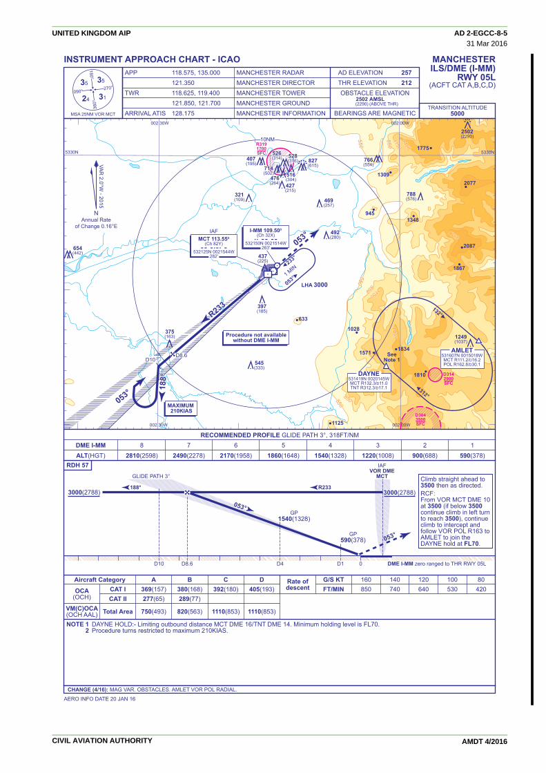
053°053°
053°
GP590(378)
GP1540(1328)
IAFVOR DME
MCTGLIDE PATH 3°
053°
30003000(2788)(2788)3000(2788)3000(2788)R233188°
550550
550550
85085011501150
550550
850850
850850 11501150
17501750
14501450
14501450
550550
8501150
550
850
850 1150
1750
14501450
233°
053°
312°
132°
10NM
R233R233R233
188°
188°
188°
I-MM 109.50D
(Ch 32X) imm
532150N 0021514W263'
MCT 113.55D
(Ch 82Y) mct
532125N 0021544W282'
D10D8.6
053°053°053°
053°
LHA 30001 M
IN
IAF
1309
1348
2087
1867
18341571
1028
633
1810
1125
945
1775
2077
AMLET531607N 0015018WMCT R111.2/D16.2POL R162.8/D30.1
DAYNE531419N 0020145WMCT R132.3/D11.0TNT R312.3/D17.1
Procedure not availablewithout DME I-MM
R319R31917001700SFCSFC
R3191700SFC
D3142900SFC
D3043500SFC
D304D30435003500SFCSFC
D3043500SFC
D3043500SFC
SeeNote 1545
(333)
437(225)
397(185)
1249(1037)
375(163)
654(442)
407(195)
714714(502)(502)
528528(316)(316)
516516(304)(304)476476
(264)(264)
714(502)
528(316)
516(304)476
(264)
526526(314)(314)526(314) 766
(554)
788(576)
2502(2290)
827(615)
427(215)
321(109) 469
(257)
492(280)
5330N 5330N
002 30W 002 00W
002 30W002 30W002 30W 002 00W
Rate ofdescent
G/S KT 160 140 120 100 80 FT/MIN 850 740 640 530 420
TRANSITION ALTITUDE5000
NOTE 1 DAYNE HOLD:- Limiting outbound distance MCT DME 16/TNT DME 14. Minimum holding level is FL70. 2 Procedure turns restricted to maximum 210KIAS.
Climb straight ahead to3500 then as directed.RCF:From VOR MCT DME 10at 3500 (if below 3500continue climb in left turnto reach 3500), continueclimb to intercept andfollow VOR POL R163 toAMLET to join theDAYNE hold at FL70.
AERO INFO DATE 20 JAN 16
MANCHESTERILS/DME (I-MM)
RWY 05L(ACFT CAT A,B,C,D)
INSTRUMENT APPROACH CHART - ICAO
CHANGE (4/16): MAG VAR. OBSTACLES. AMLET VOR POL RADIAL.
RDH 57
24
3535
31
MSA 25NM VOR MCT
090°
180°
360°
270°
NAnnual Rate
of Change 0.16°E
VAR
3.2°W - 2007
VAR
3.2°W - 2007
VAR
2.0°W - 2015
APP 118.575, 135.000 MANCHESTER RADAR 121.350 MANCHESTER DIRECTORTWR 118.625, 119.400 MANCHESTER TOWER 121.850, 121.700 MANCHESTER GROUNDARRIVAL ATIS 128.175 MANCHESTER INFORMATION
AD ELEVATION 257THR ELEVATION 212
BEARINGS ARE MAGNETIC
OBSTACLE ELEVATION2502(2290)
AMSL(ABOVE THR)
D10 D8.6 D4 D1 0 DME I-MM zero ranged to THR RWY 05L
A B C D 369(157) 380(168) 392(180) 405(193) 277(65) 289(77)
750(493) 820(563) 1110(853) 1110(853)
OCA(OCH)
Aircraft CategoryCAT ICAT II
Total AreaVM(C)OCA(OCH AAL)
DME I-MM 8 7 6 5 4 3 2 1 ALT(HGT) 2810(2598) 2490(2278) 2170(1958) 1860(1648) 1540(1328) 1220(1008) 900(688) 590(378)
RECOMMENDED PROFILE GLIDE PATH 3°, 318FT/NM
MAXIMUM 210KIAS
UNITED KINGDOM AIP AD 2-EGCC-8-531 Mar 2016
CIVIL AVIATION AUTHORITY AMDT 4/2016

053°
GP590(378)
GP1540(1328)
IAFVOR DME
MCTGLIDE PATH 3°
053°
30003000(2788)(2788)3000(2788)3000(2788)R233188°
550550
550550
85085011501150
550550
850850
850850 11501150
17501750
14501450
14501450
550550
8501150
550
850
850 1150
1750
14501450
233°
053°
312°
132°
10NM
R233R233R233
188°
188°
188°
I-MM 109.50D
(Ch 32X) imm
532150N 0021514W263'
MCT 113.55D
(Ch 82Y) mct
532125N 0021544W282'
D11.1D9.7
053°053°053°
053°
LHA 30001 M
IN
IAF
1309
1348
2087
1867
18341571
1028
633
1810
1125
945
1775
2077
AMLET531607N 0015018WMCT R111.2/D16.2POL R162.8/D30.1
DAYNE531419N 0020145WMCT R132.3/D11.0TNT R312.3/D17.1
Procedure not availablewithout DME MCT
R319R31917001700SFCSFC
R3191700SFC
D3142900SFC
D3043500SFC
D304D30435003500SFCSFC
D3043500SFC
D3043500SFC
SeeNote 1545
(333)
437(225)
397(185)
1249(1037)
375(163)
654(442)
407(195)
714714(502)(502)
528528(316)(316)
516516(304)(304)476476
(264)(264)
714(502)
528(316)
516(304)476
(264)
526526(314)(314)526(314) 766
(554)
788(576)
2502(2290)
827(615)
427(215)
321(109) 469
(257)
492(280)
5330N 5330N
002 30W 002 00W
002 30W002 30W002 30W 002 00W
Rate ofdescent
G/S KT 160 140 120 100 80 FT/MIN 850 740 640 530 420
TRANSITION ALTITUDE5000
NOTE 1 DAYNE HOLD:- Limiting outbound distance MCT DME 16/TNT DME 14. Minimum holding level is FL70. 2 Procedure turns restricted to maximum 210KIAS.
Climb straight ahead to3500 then as directed.RCF:From VOR MCT DME 10at 3500 (if below 3500continue climb in left turnto reach 3500), continueclimb to intercept andfollow VOR POL R163 toAMLET to join theDAYNE hold at FL70.
AERO INFO DATE 20 JAN 16
MANCHESTERILS/DME (MCT)
RWY 05L(ACFT CAT A,B,C,D)
INSTRUMENT APPROACH CHART - ICAO
CHANGE (4/16): MAG VAR. OBSTACLES. AMLET VOR POL RADIAL.
RDH 57
24
3535
31
MSA 25NM VOR MCT
090°
180°
360°
270°
NAnnual Rate
of Change 0.16°E
VAR
2.0°W - 2015
APP 118.575, 135.000 MANCHESTER RADAR 121.350 MANCHESTER DIRECTORTWR 118.625, 119.400 MANCHESTER TOWER 121.850, 121.700 MANCHESTER GROUNDARRIVAL ATIS 128.175 MANCHESTER INFORMATION
AD ELEVATION 257THR ELEVATION 212
BEARINGS ARE MAGNETIC
OBSTACLE ELEVATION2502(2290)
AMSL(ABOVE THR)
D11.1 D9.7 D5.1 D2.1 0 DME MCT reads 1.1NM at THR RWY 05L
A B C D 369(157) 380(168) 392(180) 405(193) 277(65) 289(77)
750(493) 820(563) 1110(853) 1110(853)
OCA(OCH)
Aircraft CategoryCAT ICAT II
Total AreaVM(C)OCA(OCH AAL)
DME MCT 9.1 8.1 7.1 6.1 5.1 4.1 3.1 2.1 ALT(HGT) 2810(2598) 2490(2278) 2170(1958) 1860(1648) 1540(1328) 1220(1008) 900(688) 590(378)
RECOMMENDED PROFILE GLIDE PATH 3°, 318FT/NM
MAXIMUM 210KIAS
UNITED KINGDOM AIP AD 2-EGCC-8-631 Mar 2016
CIVIL AVIATION AUTHORITY AMDT 4/2016

IAFVOR DME
MCT
053°
30003000(2788)(2788)3000(2788)3000(2788) 188° R233
053°
550550
550550
8508501150150
550550
850850
850850 1150
150
17501750
14501450
14501450
550550
8501150
550
850
850 1150
1750
14501450
233°
053°
312°
132°
10NM
R233R233R233
188°
188°
188°
D
MCT 113.55D
(Ch 82Y) mct
532125N 0021544W282'
I-MM D10(MCT D11.1)
I-MM D8.6(MCT D9.7)
I-MMI-MM D0 D0(MCTMCT D1.1) D1.1)
I-MM D0(MCT D1.1)
053°053°053°
053°
LHA 30001 M
IN
IAF
1309
1348
2087
1867
18341571
1028
633
1810
1125
945
1775
2077
Procedure not availablewithout DME I-MM or MCT
D3142900SFC
D3043500SFC
D304D30435003500SFCSFC
D3043500SFC
D3043500SFC
SeeNote 1
I-MM 109.50D
(Ch 32X) imm
532150N 0021514W263'
AMLET531607N 0015018WMCT R111.2/D16.2POL R162.8/D30.1
DAYNE531419N 0020145WMCT R132.3/D11.0TNT R312.3/D17.1
R319R31917001700SFCSFC
R3191700SFC
545(333)
437(225)
397(185)
1249(1037)
375(163)
654(442)
407(195)
714714(502)(502)
528528(316)(316)
516516(304)(304)476476
(264)(264)
714(502)
528(316)
516(304)476
(264)
526526(314)(314)526(314) 766
(554)
788(576)
2502(2290)
827(615)
427(215)
321(109) 469
(257)
492(280)
5330N 5330N
002 30W 002 00W
002 30W002 30W002 30W 002 00W
TRANSITION ALTITUDE 5000
MANCHESTERLOC/DMERWY 05L
(ACFT CAT A,B,C,D)
INSTRUMENT APPROACH CHART - ICAO
CHANGE (4/16): MAG VAR. OBSTACLES. AMLET VOR POL RADIAL.
24
3535
31
MSA 25NM VOR MCT
090°
180°
360°
270°
NAnnual Rate
of Change 0.16°E
VAR
2.0°W - 2015
D8.6(MCT D9.7)
D10(MCT D11.1)
0
APP 118.575, 135.000 MANCHESTER RADAR 121.350 MANCHESTER DIRECTORTWR 118.625, 119.400 MANCHESTER TOWER 121.850, 121.700 MANCHESTER GROUNDARRIVAL ATIS 128.175 MANCHESTER INFORMATION
AD ELEVATION 257THR ELEVATION 212
BEARINGS ARE MAGNETIC
OBSTACLE ELEVATION2502(2290)
AMSL(ABOVE THR)
DME I-MM(MCT) 8(9.1) 7(8.1) 6(7.1) 5(6.1) 4(5.1) 3(4.1) 2(3.1) 1(2.1) ALT(HGT) 2810(2598) 2490(2278) 2170(1958) 1860(1648) 1540(1328) 1220(1008) 900(688) 590(378)
RECOMMENDED PROFILE Gradient 5.2%, 318FT/NM
Rate ofdescent
G/S KT 160 140 120 100 80 FT/MIN 850 740 640 530 420
A B C D
640(428) 640(428) 640(428) 640(428)
750(493) 820(563) 1110(853) 1110(853)
OCA(OCH)
Aircraft Category
Procedure
Total AreaVM(C)OCA(OCH AAL)
AERO INFO DATE 20 JAN 16
NOTE 1 DAYNE HOLD:- Limiting outbound distance MCT DME 16/TNT DME 14. Minimum holding level is FL70. 2 DME MCT may be used if DME I-MM is not available. 3 Procedure turns restricted to maximum 210KIAS.
MAPt I-MM DME ZERO/ MCT DME 1.1 (THR RWY 05L)Climb straight ahead to 3500then as directed.RCF:From VOR MCT DME 10 at3500 ( if below 3500 continueclimb in left turn to reach3500), continue climb tointercept and followVOR POL R163 to AMLET tojoin the DAYNE hold at FL70.
DME I-MM zero ranged to THR RWY 05L(DME MCT reads 1.1NM at THR RWY 05L)
MAXIMUM 210KIAS
UNITED KINGDOM AIP AD 2-EGCC-8-731 Mar 2016
CIVIL AVIATION AUTHORITY AMDT 4/2016

057°
IAFVOR DME
MCT
057°
30003000(2788)(2788)3000(2788)3000(2788)
R237192°
550550
550550
85085011501150
550550
850850
850850 1150
1150
17501750
14501450
14501450
550550
8501150
550
850
850 1150
1750
14501450
233°
053°
312°
132°
10NM
R237
192°
192°
192°
I-MM 109.50D
(Ch 32X) imm
532111N 0021623W263'
MCT 113.55D
(Ch 82Y) mct
532125N 0021544W282'
057°
057°
LHA 3000
1 MIN
IAF
1309
1348
2087
1867
18341571
1028
633
1810
1125
945
1775
2077
AMLET531607N 0015018WMCT R111.2/D16.2POL R162.8/D30.1
DAYNE531419N 0020145WMCT R132.3/D11.0TNT R312.3/D17.1
Procedure not availablewithout DME MCT or I-MM
D3142900SFC
D3043500SFC
D304D30435003500SFCSFC
D3043500SFC
D3043500SFC
SeeNote 1
MCTMCT D11.1 D11.1(I-MMI-MM D10) D10)MCT D11.1(I-MM D10) MCTMCT D9.7 D9.7
(I-MMI-MM D8.6) D8.6)MCT D9.7
(I-MM D8.6)
MCTMCT D1.1 D1.1(I-MMI-MM D0) D0)MCT D1.1(I-MM D0)
R319R31917001700SFCSFC
R3191700SFC
545(333)
437(225)
397(185)
1249(1037)
375(163)
654(442)
407(195)
714714(502)(502)
528528(316)(316)
516516(304)(304)476476
(264)(264)
714(502)
528(316)
516(304)476
(264)
526526(314)(314)526(314) 766
(554)
788(576)
2502(2290)
827(615)
427(215)
321(109) 469
(257)
492(280)
5330N 5330N
002 30W 002 00W
002 30W002 30W002 30W 002 00W
Rate ofdescent
G/S KT 160 140 120 100 80 FT/MIN 850 740 640 530 420
TRANSITION ALTITUDE5000
AERO INFO DATE 20 JAN 16
MANCHESTERVOR/DMERWY 05L
(ACFT CAT A,B,C,D)
INSTRUMENT APPROACH CHART - ICAO
CHANGE (4/16): MAG VAR. OBSTACLES. AMLET VOR POL RADIAL.
24
3535
31
MSA 25NM VOR MCT
090°
180°
360°
270°
NAnnual Rate
of Change 0.16°E
VAR
3.2°W - 2007
VAR
3.2°W - 2007
VAR
2.0°W - 2015
APP 118.575, 135.000 MANCHESTER RADAR 121.350 MANCHESTER DIRECTORTWR 118.625, 119.400 MANCHESTER TOWER 121.850, 121.700 MANCHESTER GROUNDARRIVAL ATIS 128.175 MANCHESTER INFORMATION
AD ELEVATION 257THR ELEVATION 212
BEARINGS ARE MAGNETIC
OBSTACLE ELEVATION2502(2290)
AMSL(ABOVE THR)
D11.1(I-MMD10)
D9.7(I-MMD8.6)
0 DME MCT reads 1.1NM at THR RWY 05L(DME I-MM zero ranged to THR RWY 05L)
MAPt MCT DME 1.1/ I-MM DME ZERO (THR RWY 05L)Climb straight ahead to 3500then as directed.RCF: From VOR MCT DME 10at 3500 (if below 3500 continueclimb in left turn to reach 3500),continue climb to intercept andfollow VOR POL R163 toAMLET to join the DAYNE holdat FL70.
NOTE 1 DAYNE HOLD:- Limiting outbound distance MCT DME 16/TNT DME 14. Minimum holding level is FL70. 2 DME I-MM may be used if DME MCT is not available. 3 FAT offset 4° from RWY C/L and crosses RWY C/L 0.82NM (nominal) before THR RWY 05L. 4 Procedure turns restricted to maximum to 210KIAS.
A B C D
690(478) 690(478) 690(478) 690(478)
750(493) 820(563) 1110(853) 1110(853)
OCA(OCH)
Aircraft Category
Procedure
Total AreaVM(C)OCA(OCH AAL)
DME MCT(I-MM) 9.1(8) 8.1(7) 7.1(6) 6.1(5) 5.1(4) 4.1(3) 3.1(2) ALT(HGT) 2810(2598) 2490(2278) 2170(1958) 1860(1648) 1540(1328) 1220(1008) 900(688)
RECOMMENDED PROFILE Gradient 5.2%, 320FT/NM
MAXIMUM 210KIAS
UNITED KINGDOM AIP AD 2-EGCC-8-831 Mar 2016
CIVIL AVIATION AUTHORITY AMDT 4/2016

233°
GPGP620620(371)(371)
GP620(371)
GP1580(1331)
GP2860(2611)
IAFVOR DME
MCT GLIDE PATH 3°
358°/233°
3500350035003500
(3251)
R053 008°
550550
550550
550550
850850
850850 11501150
17501750
14501450
14501450
550550
550
850
850 1150
1750
14501450
233°053°
10NM
008°
008°
008°
008°
008°
I-NN 109.50D
(Ch 32X) inn
532027N 0021806W263'
MCT 113.55D
(Ch 82Y) mct
532125N 0021544W282'
D12
D10
233°
R053R053R053
358°
LHA 30001 M
IN
IAF
1309
1348
2087
1867
18341571
1028
633
1810
1125
945
1775
2077
Procedure not availablewithout DME I-NN
D3142900SFC
D3043500SFC
D304D30435003500SFCSFC
D3043500SFC
D3043500SFC
R319R31917001700SFCSFC
R3191700SFC
545(296)
437(188)
397(148)
1249(1000)
375(126)
654(405)
407(158)
714714(465)(465)
528528(279)(279)
516516(267)(267)476476
(227)(227)
714(465)
528(279)
516(267)476
(227)
526526(277)(277)526(277) 766
(517)
788(539)
2502(2253)
827(578)
427(178)
321(72) 469
(220)
492(243)
ROSUN534008N 0022057WMCT R352.7/D19.0
BURNI534338N 0023104WMCT R339.9/D24.0
MCTD24
353°
173°
HOLDINGMNM FL70
(5000 after MAP)
5330N
002 30W 002 00W
002 30W002 30W002 30W 002 00W
Rate ofdescent
G/S KT 160 140 120 100 80 FT/MIN 850 750 640 530 430
TRANSITION ALTITUDE5000
NOTE 1 In the event of RCF follow the standard MAP on to track 358°. At MCT DME 10 turn direct to BURNI (MCT R340/MCT DME 24) climbing to 5000 to enter the ROSUN hold. Aircraft unable to make 3500 before MCT DME 10, commence climbing turn left to 3500 at MCT DME 10. At 3500 or above continue left turn and proceed direct to BURNI. 2 To ensure separation from departing traffic on RWY 23L, aircraft carrying out MAP should expedite the climb through 750(501) before commencing the right turn onto track 358°. 3 Procedure turns restricted to maximum 185KIAS.
Climb to 3500 - straight aheaduntil passing 750 or I-NN DMEZERO inbound, whichever islater, then turn right onto track358° then as directed.RCF: See note 1 below.
AERO INFO DATE 19 JAN 16
MANCHESTERILS/DME (I-NN)
RWY 23R(ACFT CAT A,B,C,D)
INSTRUMENT APPROACH CHART - ICAO
CHANGE (4/16): MAG VAR. OBSTACLES.
RDH 55
24
3535
31
MSA 25NM VOR MCT
090°
180°
360°
270°
NAnnual Rate
of Change 0.16°E
VAR
2.0°W - 2015
APP 118.575, 135.000 MANCHESTER RADAR 121.350 MANCHESTER DIRECTORTWR 118.625, 119.400 MANCHESTER TOWER 121.850, 121.700 MANCHESTER GROUNDARRIVAL ATIS 128.175 MANCHESTER INFORMATION
AD ELEVATION 257THR ELEVATION 249
BEARINGS ARE MAGNETIC
OBSTACLE ELEVATION2502(2253)
AMSL(ABOVE THR)
D10 D12D8D4D10DME I-NN zero ranged to THR RWY 23R
DME I-NN 9 8 7 6 5 4 3 2 1 ALT(HGT) 3180(2931) 2860(2611) 2540(2291) 2220(1971) 1900(1651) 1580(1331) 1260(1011) 940(691) 620(371)
RECOMMENDED PROFILE GLIDE PATH 3°, 320FT/NM
A B C D 396(147) 409(160) 421(172) 435(186) 306(57) 317(68) 331(82) 351(102)
750(493) 820(563) 1110(853) 1110(853)
OCA(OCH)
Aircraft CategoryCAT ICAT II
Total AreaVM(C)OCA(OCH AAL)
MAXIMUM185KIAS
UNITED KINGDOM AIP AD 2-EGCC-8-931 Mar 2016
CIVIL AVIATION AUTHORITY AMDT 4/2016

UNITED KINGDOM AIP AD 2.EGCC-126 May 2016
EGCC — MANCHESTEREGCC AD 2.1 AERODROME LOCATION INDICATOR AND NAME
EGCC — MANCHESTER
EGCC AD 2.2 AERODROME GEOGRAPHICAL AND ADMINISTRATIVE DATA
1 ARP coordinates and site at AD Lat: 532114N Long: 0021630WMid point of Runway 05L/23R.
2 Direction and distance from city 7.5 nm SW of Manchester.
3 Elevation / Reference temperature 257 ft / 18 C
4 Geoid undulation at AD ELEV PSN 167 FT
5 Magnetic Variation/ Annual Change 1.53°W (2017) / 0.16° →→6 AD Administration, address, telephone, telefax, AFS, e- MANCHESTER AIRPORT PLC
mail address, website address Post: Manchester Airport, Manchester M90 1QXPhone: 0161-209 2835 (ATC)Phone: 0161-489 3331 (Airfield Duty Manager)Phone: 0161-499 5502 (AFTN)Phone: 0871-271 0711 (Manchester Airport PLC - General Enquiries)Phone: 0161-493 1850 (Airport Co-ordination Ltd - PPR Mon-Fri; 0900-1700)Fax: 0161-489 2889 (Airfield Duty Manager)Fax: 0161-499 5501 (AFTN)AFS: EGCC
7 Type of Traffic permitted (IFR/VFR) IFR/VFR
8 Remarks All telephone calls to ATC will be recorded.
EGCC AD 2.3 OPERATIONAL HOURS
1 Aerodrome Operator H24
2 Customs and Immigration H24
3 Health and sanitation H24(Port Health)
4 AIS Briefing Office
5 ATS Reporting Office (ARO)
6 MET Briefing Office
7 Air Traffic Service H24See also AD 2.18.
8 Fuelling H24
9 Handling H24
10 Security H24
11 De-icing H24
12 Remarks Refer to AD 2.20 item 1.
EGCC AD 2.4 HANDLING SERVICES AND FACILITIES
1 Cargo handling facilities HILOs 15 and 18.6 m and 9 m conveyor belts. 9 ton fork lift. Nearestrailway siding: Heald Green 1.3 nm
2 Fuel and oil types AVTUR JET A-1 (anti-icing additive not included).W80, W100 and W12098, 390, 500.
3 Fuelling facilities/capacity Hydrants at all pier stands for AVTUR JET A-1. No over-wing fuelling.
4 De-icing facilities Contact: Swissport, Airline Services.
5 Hangar space for visiting aircraft Limited. Signature Flight Support. →6 Repair facilities for visiting aircraft By arrangement with Flybe, Monarch, Signature Flight Support, Thomas →Cook.
7 Remarks Oxygen and related servicing, by arrangement with handling agent.
A nominated handling agent is Mandatory for all visiting aircraft.
CIVIL AVIATION AUTHORITY AMDT 6/2016

AD 2.EGCC-2 UNITED KINGDOM AIP26 May 2016
EGCC AD 2.4 HANDLING SERVICES AND FACILITIES (continued)
AMDT 6/2016
Signature Flight Support – Tel: 0161-436 6666. Fax: 0161-436 3450.← E-mail: [email protected]. Telex: 668777.← VHF Company Frequency 130.650 MHz (Northside facility).←←Premiere Handling – Tel: 07958 877 500Email: [email protected]
Other handling agents based at Manchester are:Menzies – Swissport – dnata – WFS UK – Aviator – ASIG
EGCC AD 2.5 PASSENGER FACILITIES
1 Hotels 6
2 Restaurants Restaurants in all Terminals.
3 Transportation Buses, trains, taxis and car hire. Nearest railway station: Airport.
4 Medical facilities Medical Response H24 - First aid only.
5 Bank and Post Office Post office Terminal 1. Bureau de Change.
6 Tourist Office
7 Remarks
EGCC AD 2.6 RESCUE AND FIRE FIGHTING SERVICES
1 AD category for fire fighting RFF Category A10
2 Rescue equipment
3 Capability for removal of disabled aircraft 170,000 kg. Contact 0161-489 3331 (Airfield Duty Manager).
4 Remarks
EGCC AD 2.7 SEASONAL AVAILABILITY - CLEARING
1 Type of clearing equipment Mechanical, Chemical anti-icing.
2 Clearance priorities During snowfall, aerodrome may be SNOCLO and Runway 05R/23L maynot be cleared and available.
3 Remarks Latest information from Snow State/Clearance Programme Tel: 0161-4893331 (Airfield Duty Manager).
EGCC AD 2.8 APRONS, TAXIWAYS AND CHECK LOCATIONS/POSITIONS DATA
1 Apron surface and strength Surface: Concrete.PCN 56/R/C/W/T
Surface: Concrete.PCN 97/R/B/W/T
2 Taxiway width, surface and strength Taxiway ALPHA: 23 m. Surface: Concrete and asphalt.PCN 66/F/C/W/TPCN between Alpha-Echo and Bravo: 46 F/C/W/T
Taxiway SIERRA: 23 m. Surface: Concrete and asphalt.PCN 79/R/C/W/T
Taxiway TANGO: 23 m. Surface: Concrete and asphalt.PCN 79/R/C/W/T
Taxiway UNIFORM: 23 m. Surface: Concrete and asphalt.PCN 79/R/C/W/T
Taxiway VICTOR: 23 m. Surface: Concrete and asphalt.PCN 79/R/C/W/T
Taxiway VICTOR ALPHA: 23 m. Surface: Concrete and asphalt.PCN 79/R/C/W/T
Taxiway VICTOR BRAVO: 23 m. Surface: Concrete and asphalt.
CIVIL AVIATION AUTHORITY

UNITED KINGDOM AIP AD 2.EGCC-326 May 2016
EGCC AD 2.8 APRONS, TAXIWAYS AND CHECK LOCATIONS/POSITIONS DATA (continued)
AMDT 6/2016
PCN 79/R/C/W/T
Taxiway VICTOR CHARLIE: 23 m. Surface: Concrete and asphalt.PCN 79/R/C/W/T
Taxiway WHISKEY: 23 m. Surface: Concrete and asphalt.PCN 79/R/C/W/T
Taxiway YANKEE: 23 m. Surface: Concrete and asphalt.PCN 79/R/C/W/T
Taxiway OTHER TAXIWAYS: 23 m. Surface: Concrete and asphalt.PCN 95/R/C/W/T
3 Altimeter checkpoint location and elevation Pier A: 240 - 243 ft amsl. Pier B: 233 - 236 ft amsl. Pier C: 228 - 232 ftamsl. Western Apron 221 - 231 ft amsl. Apron 238 ft amsl.
4 VOR checkpoints
5 INS checkpoints See Aircraft Ground Movement/Parking/Docking Chart
6 Remarks Taxiways Quebec and Papa may be used for aircraft parking. In darknessor if Low Visibility Procedures are in force a ‘Follow-me’ vehicle will beprovided.
Stands 100 and 101 have localised slopes in excess of ICAO require-ments. Downward slopes of 1.5% from centre of stand towards TaxiwayDelta.
EGCC AD 2.9 SURFACE MOVEMENT GUIDANCE AND CONTROL SYSTEM AND MARKINGS
1 Use of aircraft stand ID signs, TWY guide lines and visual Terminal 1 comprises Stands 1-12, 15, 21-29, 31 and 32. Stand 12 hasdocking/parking guidance system of aircraft stands additional centre-lines designated 12L and 12R. Aircraft docking on all
Terminal 1 stands (except Stands 12L and 21) is by Safedock. Aircraftdocking on Stands 12L and 21 is by Marshaller’s instructions.
Terminal 2 has a single pier serving Stands 201-215. Stands 201, 203, →205, 207, 209, 211, 213 and 215 have a single centre-line. Stands 202,204, 206, 208, 210, 212 and 214 have two centre-lines. The main →(widebody) centre-line is designated by the stand number only. Thesubsidiary centre-line is designated Left. For example; Stand 206 and206L. Aircraft docking on all Terminal 2 stands (except Stand 201) is by →Safedock. Aircraft docking on Stand 201 is by Marshaller’s instructions. →Terminal 3 comprises pier served Stands 16-18, 41-44 and 47-55, and →→remote Stands 56-58. Stand 44 has additional centre-lines designated44L and 44R. Aircrews are to note that Stands 44L and 44R aredemarked by alternate yellow/white dashed painted centre-lines. Aircraftdocking on all Terminal 3 stands is by Safedock (except Stands 44 and56-58). Aircraft docking on Stands 44 and 56-58 is by Marshaller’sinstructions.
Stands 100 and 101 are located on an island between Taxiways Deltaand Lima. Stand 100 can accommodate aircraft with a maximum →→wingspan of 31 m. Stand 101 can accommodate aircraft with a maximumwingspan of 29 m. Aircraft to enter stands from Taxiway Delta only, and →to exit via Taxiway Lima only. Aircraft parking is by Marshaller’s →instructions.
Remote stands 61-74 and 80-86 have additional centre-lines designated →→Left and Right. Stands 217-219 and 231-249 have a single centre-line. →→Stand 216 has two centre-lines, designated 216 and 216R. →Aircrew are to note that all stand entry guidance systems are activated bytheir ground handling agent. Pilots must not enter an aircraft stand unlessthe Stand Entry Guidance has been activated and the correct aircraft typeis displayed, or a MA marshaller has signalled clearance to proceed. Inthe event of there being no activated SEG upon approach to a stand,flight crews must hold position on the taxiway and advise GMC. Flightcrews must not attempt to self-park.
2 Runway and taxiway markings and lighting Runway marking aid(s):05L/23R: Runway designation. Runway threshold, runway centre-line,edge, TDZ and fixed distances. Runway width is designated by sidestripe markings.05R/23L: Runway designation. Runway threshold, runway centre-line,edge, TDZ and fixed distances. Runway width is designated by sidestripe markings. Turning circle has unlit painted yellow centre-line andinset blue edge lighting beyond runway edges.
Taxiway marking aid(s):: Green centre-line with blue edge lights on sharp curves, red stop bars atholding points. Runway Exits have alternate green/yellow centre-linelights to the edge of the localiser sensitive area. Runway Taxi holdingposition. Runway Guard lights. Taxiways Quebec and Papa have paintedyellow centre-lines only - during Sunset to Sunrise these taxiways only tobe used with a Follow-Me vehicle.
CIVIL AVIATION AUTHORITY

AD 2.EGCC-4 UNITED KINGDOM AIP26 May 2016
EGCC AD 2.9 SURFACE MOVEMENT GUIDANCE AND CONTROL SYSTEM AND MARKINGS(continued)
AMDT 6/2016
3 Stop bars Stopbars at runway entrance points are in operation H24
4 Remarks Some obstacle marking. Illuminated wind direction indicators.
Pilot attention is drawn to the use of additional paint markings at specifiedrunway entrance and exit points. These markings are provided as anadditional measure to raise situational awareness and to reduce therunway incursion risk.
Additional markings for ‘NO ENTRY’ are located at the exit point RET AE.
All Ground Movement is under ATC Control.
EGCC AD 2.10 AERODROME OBSTACLES
In Approach/Take-off areas
Obstacle ID/Designation Obstacle Obstacle Elevation/Height Obstruction Lighting RemarksType Position Type/Colour
1 2 3 4 5 6
23R/APPROACH 05L/TAKE-OFF Hotel 532150.28N 285 ft Yes0021528.83W
23L/APPROACH Tree 532056.86N 255 ft No0021621.94W
In circling area and at aerodrome
Obstacle ID/Designation Obstacle Obstacle Elevation/Height Obstruction Lighting RemarksType Position Type/Colour
1 2 3 4 5 6
Control 532126.64N 434 ft NoTower 0021646.98W
Tree 532105.47N 345 ft No0021354.38W
Electricity 531905.19N 397 ft NoPylon 0021705.85W
EGCC AD 2.11 METEOROLOGICAL INFORMATION PROVIDED
1 Associated MET Office MET OFFICE EXETER.
2 Hours of service H24MET Office outside hours
3 Office responsible for TAF preparation MET OFFICE EXETER.Periods of validity 30 Hours
4 Trend forecast TRENDInterval of issuance 30 minutes.
5 Briefing/consultation provided
6 Flight documentationLanguage(s) used
7 Charts and other information available for briefing orconsultation
8 Supplementary equipment available for providing infor-mation
9 ATS units provided with information MANCHESTER.
10 Additional information (limitation of service, etc.) Current weather on ATIS.
CIVIL AVIATION AUTHORITY

UNITED KINGDOM AIP AD 2.EGCC-531 Mar 2016
EGCC AD 2.12 RUNWAY PHYSICAL CHARACTERISTICS
Designations RWY True bearing Dimensions of RWY Surface of RWY/ THR co-ordinates/ THR elevation/Number SWY/ THR Geoid undu- Highest elevation of
Strength (PCN) lation TDZ of precision APPRWY
1 2 3 4 5 6
05L 051.06° 3048 x 45 m RWY surface: 532051.20N THR 212 ftPCN 94/F/C/W/T 0021715.95W →Concrete/Un-grooved 167 ftAsphalt
23R 231.09° 3048 x 45 m RWY surface: 532140.75N THR 249 ftPCN 94/F/C/W/T 0021533.41W →Concrete/Un-grooved 167 ftAsphalt
05R 051.04° 3050 x 45 m RWY surface: 531955.10N THR 186 ftPCN 79/F/C/W/T 0021838.38W →Concrete/Grooved As- 167 ftphalt
23L 231.07° 3050 x 45 m RWY surface: 532053.35N THR 227 ftPCN 79/F/C/W/T 0021637.95W →Concrete/Grooved As- 167 ftphalt
Slope of RWY/ SWY dimensions Clearway dimensions Strip Dimensions OFZ RemarksSWY
7 8 9 10 11 12
05L - 0.49% Up 23R - 215 x m x 300 m Yes RWY 05L0.49% Down
RWY 05L LandingThreshold Displacedby 427 m.
05L/23R Runwayshoulders are widenedto 23 m each sidegiving a total pavedwidth of 91 m.
05L/23R has a turningcircle at thenortheastern end,abeam Link Juliet, foruse by aircraft up toA380.
All turning circles haveunlit painted centre-line and blue edgelighting beyond runwayedges. Aircraft shouldfollow the paintedcentre-line in a clock-wise direction, unlessdirected otherwise byATC
RESA’s are: Runway05L: 240 x 90 m
STRIP DIMENSIONS05L/23R: 300 m wideover full length ex-tending to 60 m be-yond each end ofpavement.
05L - 0.49% Up 23R - 300 x m x 300 m Yes RWY 23R0.49% Down
RWY 23R LandingThreshold Displaced183 m.
05L/23R Runwayshoulders are widenedto 23 m each sidegiving a total pavedwidth of 91 m.
05L/23R has a turningcircle at thenortheastern end,abeam Link Juliet, foruse by aircraft up toA380.
CIVIL AVIATION AUTHORITY AMDT 4/2016

AD 2.EGCC-6 UNITED KINGDOM AIP31 Mar 2016
EGCC AD 2.12 RUNWAY PHYSICAL CHARACTERISTICS (continued)
AMDT 4/2016
Slope of RWY/ SWY dimensions Clearway dimensions Strip Dimensions OFZ RemarksSWY
7 8 9 10 11 12
The last quarter ofRunway 23R has adownslope of 0.88%
All turning circles haveunlit painted centre-line and blue edgelighting beyond runwayedges. Aircraft shouldfollow the paintedcentre-line in a clock-wise direction, unlessdirected otherwise byATC
RESA’s are: Runway23R: 240 x 90 m
STRIP DIMENSIONS05L/23R: 300 m wideover full length ex-tending to 60 m be-yond each end ofpavement.
05R - 0.46% Up 23L - 300 x m x 300 m Yes RWY 05R0.48% Down
05R/23L has one turn-ing circle: At 1820 mfrom 23L threshold foruse by aircraft up toB767;
All turning circles haveunlit painted centre-line and blue edgelighting beyond runwayedges. Aircraft shouldfollow the paintedcentre-line in a clock-wise direction, unlessdirected otherwise byATC
RESA’s are: Runway05R: 351 x 90 m
STRIP DIMENSIONS05R/23L: 300 m wideover full length from 60m beyond end of pave-ment, except betweenlinks Victor Alpha andTango where strip nar-rows to 56 m on thesouthern side of Run-way 23L starter exten-sion only
05R - 0.46% Up 23L - 300 x m x 300 m Yes RWY 23L0.48% Down
Runway 23L has astarter extension of150 x 30 m. Hardshoulder width atstarter extension is 15m. Hard innershoulders along fulllength of Runway 05R/23L have a width of 7.5m and a PCN of 42 R/C/W/T. A stabilisedgrass outer shoulder isprepared to a width of7.5 m along the fulllength of the runway.
05R/23L has one turn-ing circle: At 1820 mfrom 23L threshold foruse by aircraft up toB767;
All turning circles haveunlit painted centre-line and blue edgelighting beyond runway
CIVIL AVIATION AUTHORITY

UNITED KINGDOM AIP AD 2.EGCC-731 Mar 2016
EGCC AD 2.12 RUNWAY PHYSICAL CHARACTERISTICS (continued)
AMDT 4/2016
Slope of RWY/ SWY dimensions Clearway dimensions Strip Dimensions OFZ RemarksSWY
7 8 9 10 11 12
edges. Aircraft shouldfollow the paintedcentre-line in a clock-wise direction, unlessdirected otherwise byATC
RESA’s are: Runway23L: 242 x 90 m
STRIP DIMENSIONS05R/23L: 300 m wideover full length from 60m beyond end of pave-ment, except betweenlinks Victor Alpha andTango where strip nar-rows to 56 m on thesouthern side of Run-way 23L starter exten-sion only
EGCC AD 2.13 DECLARED DISTANCES
Runway desig- TORA TODA ASDA LDA Remarksnator
1 2 3 4 5 6
05L 3014 m 3229 m 3014 m 2587 m
23R 2897 m 3197 m 2897 m 2714 m
05L 2036 m 2251 m 2036 m Take-off from intersection at TaxiwayBravo.
05L 2771 m 2986 m 2771 m Take-off from intersection at TaxiwayAlpha Golf.
05L 2432 m 2647 m 2432 m Take-off from intersection at TaxiwayAlpha Fox
23R 2567 m 2867 m 2567 m Take-off from intersection at TaxiwayMike.
23R 2121 m 2421 m 2121 m Take-off from intersection at Taxiway Ho-tel.
05R 3047 m 3347 m 3047 m 2864 m
23L 3200 m 3500 m 3200 m 2864 m Using 150 m starter exention TORA of3200 m and TODA of 3500 m available.Use Taxiway T for access
23L 3121 m 3421 m 3121 m Take-off from intersection at Taxiway Vic-tor Alpha.
23L 2955 m 3255 m 2955 m Take-off from intersection at Taxiway Vic-tor Bravo.
23L 2849 m 3149 m 2849 m Take-off from intersection at Taxiway Uni-form.
23L 2504 m 2804 m 2504 m Take-off from intersection at Taxiway Vic-tor Charlie
EGCC AD 2.14 APPROACH AND RUNWAY LIGHTING
RWY Approach Threshold VASIS/ TDZ Runway Runway Runway Stopway Remarkslighting lighting MEHT/ lighting Centre Line edge end lightingType/ Colour/ PAPI Length lighting lighting lighting Length/Length/ Wing bars Length/ Length/ Colour/ ColourIntensity Spacing/ Spacing/ Wing bars
Colour/ Colour/Intensity Intensity
1 2 3 4 5 6 7 8 9 10
05L 914 m HI Green with PAPI 900 M Colour coded Bi-directional Red. Approach Lighting:Light intensity flush HI Green Right/3° 15 m spacing flush fitted HI Coded centre-line with fivehigh. wingbars 62 ft HI 60 m spacing crossbars
CIVIL AVIATION AUTHORITY
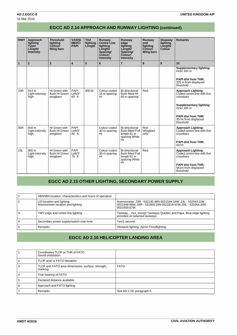
AD 2.EGCC-8 UNITED KINGDOM AIP31 Mar 2016
EGCC AD 2.14 APPROACH AND RUNWAY LIGHTING (continued)
AMDT 4/2016
RWY Approach Threshold VASIS/ TDZ Runway Runway Runway Stopway Remarkslighting lighting MEHT/ lighting Centre Line edge end lightingType/ Colour/ PAPI Length lighting lighting lighting Length/Length/ Wing bars Length/ Length/ Colour/ ColourIntensity Spacing/ Spacing/ Wing bars
Colour/ Colour/Intensity Intensity
1 2 3 4 5 6 7 8 9 10
Supplementary lighting:inner 300 m
PAPI dist from THR:325 m from displacedthreshold
23R 914 m HI Green with PAPI 900 M Colour coded Bi-directional Red. Approach Lighting:Light intensity flush HI Green Left/3° 15 m spacing flush fitted HI Coded centre-line with fivehigh. wingbars 60 ft HI 60 m spacing crossbars
Supplementary lighting:inner 300 m
PAPI dist from THR:357m from displacedthreshold
05R 900 m HI Green with PAPI Colour coded Bi-directional Red Approach Lighting:Light intensity flush HI Green Left/3° 30 m spacing flush fitted Full Wingbars Coded centre-line with fivehigh. wingbars 66 ft HI length 61 m only crossbars
spacing WhiteHI
PAPI dist from THR:437m
23L 900 m HI Green with PAPI Colour coded Bi-directional Red. Approach Lighting:Light intensity flush HI Green Left/3° 30 m spacing flush fitted Full Coded centre-line with fivehigh. wingbars 75 ft HI length 61 m crossbars
spacing WhiteHI
PAPI dist from THR:561m from displacedthreshold
EGCC AD 2.15 OTHER LIGHTING, SECONDARY POWER SUPPLY
1 ABN/IBN location, characteristics and hours of operation
2 LDI location and lighting Anemometer: 23R - 532130.48N 0021544.16W, 23L - 532043.10NAnemometer location and lighting 0021648.99W, 05R - 531959.29N 0021819.61W, 05L - 532054.33N
0021659.67W.
3 TWY edge and centre line lighting Taxiway: . Yes, except Taxiways Quebec and Papa. Blue edge lightingprovided on selected taxiways.
4 Secondary power supply/switch-over time Yes/1 second.
5 Remarks Obstacle lighting. Apron Floodlighting.
EGCC AD 2.16 HELICOPTER LANDING AREA
1 Coordinates TLOF or THR of FATOGeoid undulation
2 TLOF and/ or FATO elevation
3 TLOF and FATO area dimensions, surface, strength, FATO :marking
4 True bearing of FATO
5 Declared distance available
6 Approach and FATO lighting
7 Remarks See AD 2.20, paragraph 5.
CIVIL AVIATION AUTHORITY

UNITED KINGDOM AIP AD 2.EGCC-910 Dec 2015
EGCC AD 2.17 AIR TRAFFIC SERVICES AIRSPACE
Designation and Vertical Limits Airspace ATS unit callsign/ Transition Remarkslateral limits Class language Altitude
1 2 3 4 5 6
MANCHESTER CTR Upper limit: 3500 ft ALT D MANCHESTER RADAR 5000 ft →533011N 0024123W - Lower limit: SFC English533124N 0023102W -532056N 0023103W -532638N 0022258W -533430N 0020400W -532730N 0015400W -531616N 0020131W -531055N 0022207W -531050N 0023224W -531130N 0023744W -532708N 0023744W -533011N 0024123W
MANCHESTER CTA 1 Upper limit: 3500 ft ALT D MANCHESTER RADAR 5000 ft →533430N 0020400W - Lower limit: 2500 ft ALT English532734N 0030310W -533200N 0025000W -533430N 0020400W
MANCHESTER CTA 2 Upper limit: 3500 ft ALT D MANCHESTER RADAR 5000 ft →531047N 0020459W - Lower limit: 2500 ft ALT English530602N 0022246W -530626N 0024349W -531427N 0030140W -531050N 0023224W -531055N 0022207W -531616N 0020131W -531047N 0020459W
MANCHESTER CTA 3 Upper limit: 3500 ft ALT D MANCHESTER RADAR 5000 ft →533650N 0015216W - Lower limit: 3000 ft ALT English532719N 0014617W -532656N 0015000W -530732N 0020056W -531047N 0020459W -532730N 0015400W -533430N 0020400W -533650N 0015216W
MANCHESTER CTA 4 Upper limit: 3500 ft ALT D MANCHESTER RADAR 5000 ft →533011N 0024123W - Lower limit: 2500 ft ALT English532708N 0023744W -531130N 0023744W -531309N 0025059W -532902N 0025059W -533011N 0024123W
MANCHESTER CTA 5 Upper limit: 3500 ft ALT D MANCHESTER RADAR 5000 ft →533124N 0023102W - Lower limit: 2000 ft ALT English532056N 0023103W -532638N 0022258W -533430N 0020400W -533124N 0023102W
MANCHESTER ATZ Upper limit: 2000 ft D MANCHESTER RADAR 5000 ft →A circle, 2.5 nm radius centred at Lower limit: SFC English532114N 0021630W on longestnotified runway (05L/23R)
EGCC AD 2.18 AIR TRAFFIC SERVICES COMMUNICATION FACILITIES
Service Designation Callsign Channel(s) Hours of RemarksOperation
1 2 3 4 5
APP MANCHESTER 118.575 MHz H24 ATZ hours coincident with Ap-RADAR DOC 40 nm/15,000 ft. proach hours.
135.000 MHz As Directed by ATCDOC 40 nm/15,000 ft.
MANCHESTER DI- 121.350 MHz As Directed by ATCRECTOR DOC 25 nm/10,000 ft.
TWR MANCHESTER 118.625 MHz H24TOWER DOC 25 nm/10,000 ft.
119.400 MHz H24DOC 25 nm/10,000 ft.
MANCHESTER DELIV- 121.700 MHz Winter: 0630-2200 Summer:
CIVIL AVIATION AUTHORITY AMDT 13/2015

AD 2.EGCC-10 UNITED KINGDOM AIP26 May 2016
EGCC AD 2.18 AIR TRAFFIC SERVICES COMMUNICATION FACILITIES (continued)
AMDT 6/2016
Service Designation Callsign Channel(s) Hours of RemarksOperation
1 2 3 4 5
ERY Departing aircraft are to 0530-2100make initial call on121.700 MHz to`Manchester Delivery'or `Manchester Ground'as appropriate
MANCHESTER 121.850 MHz Winter: 0630-2200 Summer:GROUND DOC 5 nm/GND 0530-2100
MANCHESTER 121.700 MHz Winter: 2200-0630 Summer:GROUND Departing aircraft are to 2100-0530
make initial call on121.700 MHz to`Manchester Delivery'or `Manchester Ground'as appropriate
Arrival ATIS MANCHESTER IN- 128.175 MHz H24FORMATION DOC 60 nm/20,000 ft.
MANCHESTER IN- 113.550 MHz H24FORMATION Broadcast on
Manchester VORDOC 60 nm/20,000 ft.
Departure ATIS MANCHESTER DE- 121.975 MHz H24 Also available by telephone:PARTURE INFOR- DOC 5 nm/GND. 0161-209 2860.MATION
ATIS broadcast does not in-clude NOTAM information andshould not be solely reliedupon for flight planning pur-poses.
Other MANCHESTER FIRE 121.600 MHz Available when Fire vehicle onNon-ATS Frequency the ground attending aircraft in
an emergency
EGCC AD 2.19 RADIO NAVIGATION AND LANDING AIDS
Type of Aid Ident Frequency Hours of Position of Elevation of DME RemarksCAT of ILS/MLS Operation transmitting transmitting(For VOR/ILS/MLS, antenna co- antennagive VAR) ordinates
1 2 3 4 5 6 7
ILS IMM 109.500 MHz HO 532149.90NIII 0021514.46W1.53°W (2017)←←ILS/GP IMM 332.600 MHz HO 532053.81N 3° ILS Ref Datum
0021700.17W Hgt 57 ft.
ILS INN 109.500 MHz HO 532026.80N False LocaliserIII 0021806.41W Capture may be ex-1.53°W (2017) perienced when ap-←← proaching Rwy 23R
from the North andSouth.
ILS/GP INN 332.600 MHz HO 532131.27N 3° ILS Ref Datum0021542.66W Hgt 55 ft.
DME IMM 32X 532111.39N 263 ft DME I MM (RWY109.500 MHz 0021623.02W 05L)
Range 15 nm.Zero range indi-cated at THR of run-way in use.DME freq pairedwith ILS I MM and INN.
ILS IMC 111.550 MHz HO 532105.45NI 0021612.92W1.53°W (2017)←←ILS/GP IMC 332.750 MHz HO 531958.49N 3° ILS Ref Datum
0021820.74W Hgt 50 ft.
DME IMC 52Y HO 531958.58N 200 ft111.550 MHz 0021820.74W
CIVIL AVIATION AUTHORITY

UNITED KINGDOM AIP AD 2.EGCC-1110 Dec 2015
EGCC AD 2.19 RADIO NAVIGATION AND LANDING AIDS (continued)
AMDT 13/2015
Type of Aid Ident Frequency Hours of Position of Elevation of DME RemarksCAT of ILS/MLS Operation transmitting transmitting(For VOR/ILS/MLS, antenna co- antennagive VAR) ordinates
1 2 3 4 5 6 7
DME/VOR MCT 82Y Hours of operation 532125.29N 282 ftfor aerodrome pur- 0021544.24Wposes: HO
DME INN 32X HO 532111.39N 263 ft I NN (RWY 23R)109.500 MHz 0021623.02W Range 15 nm.
Zero range indi-cated at THR of run-way in use.DME freq pairedwith ILS I MM and INN.
EGCC AD 2.20 LOCAL TRAFFIC REGULATIONS
1 Airport Regulations
(a) Use governed by regulations applicable to Manchester CTR.
(b) All aircraft inbound to Manchester are to report aircraft type, latest ATIS received and cleared level on first contact withManchester Approach.
(c) All flights are at all times subject to PPR. The filing of a flight plan with NATS Ltd does not constitute permission to useManchester Aerodrome.
(d) Available H24, subject to the procedure and requirements listed at paragraph (f).
(e) Subject to paragraph g Operators of General and Business Aviation aircraft may only operate it they obtain permission todo so from the aerodrome operator in advance of each movement.
(f) Applications for prior permission and runway slots should be addressed as follows:
(i) All requests for slots during office hours (0900-1700 local) are to be directed to Airport Co-ordination Ltd (ACL) Tel:0161-493 1850/1851/1852, E-mail: [email protected], SITA: LONACXH;
(ii) Slots outside office hours can be requested from Manchester Airport Plc, Airfield Operations, Tel: 0161-489 3657
These applications must include the following information:
(1) Aircraft Owner/Operator;
(2) aircraft type and registration;
(3) flight number (if applicable);
(4) Requested time of arrival and departure at Manchester;
(5) Nominated handling agent at Manchester.
(g) Diversion Procedure — All operators are advised that before filing Manchester as an alternate, they are required to havemade arrangements for ground handling; this arrangement is subject to the agreement of the Airport Management.Nothing in this procedure shall, however, prevent an aircraft that has declared an emergency from landing.
(h) Fixed Electrical Ground Power must be used wherever available and serviceable. Use of GPU and APU should be limitedto minimise environmental impact.
2 Ground Movement
(a) All surface movement of aircraft, vehicles and persons on the Manoeuvring area is subject to ATC authority.
(b) Start-Up Procedures
(i) ATC are responsible for clearance delivery.
(ii) Pilots are requested to call Manchester Delivery for ATC clearance (stating aircraft type, stand number and codeletter of latest ATIS received) at least 10 minutes, but not more than 15 minutes before start-up to allow for departuredata to be processed.
(iii) Start up and push-back clearance is given by Ground Movement Control. Start-up approval does not implyapproval to push-back.
(iv) Pilots are required to inform Clearance Delivery when ready to start.
(v) When requesting start-up or push-back pilots should give the full call sign, type and stand number. Aircraft must beready in all respects to start and if necessary push-back before calling on the appropriate frequency. Pilots shouldonly request push-back when they are actually ready to do so.
CIVIL AVIATION AUTHORITY

AD 2.EGCC-12 UNITED KINGDOM AIP10 Dec 2015
EGCC AD 2.20 LOCAL TRAFFIC REGULATIONS (continued)
AMDT 13/2015
(vi) When requesting push-back clearance, pilots are to inform ATC if headset communication with ground crew is notestablished. Push back clearance must not be requested until the ground crew has confirmed to the flight deck thatthe aircraft is closed up and the tug is manned and fully ready to move.
(vii) If within 30 minutes of a previously issued CTOT the flight is unable to comply with that CTOT, the pilot shouldadvise Manchester Delivery as soon as possible.
(viii) Pilots are advised that delays in excess of 10 minutes can be expected at the Holding Point during busy morningand evening periods. Sufficient time should be allowed for start, push-back and taxi to take account of such a delayespecially if to comply with an CTOT.
(c) Manchester Delivery will be responsible for:
(i) passing ATC clearance to aircraft prior to start-up. Push-back approval will not be given.
(d) Ground Movement Control (GMC) will be responsible for:
(i) the surface movement of all aircraft on the manoeuvring area excluding the runway(s) in use;
(ii) issuing start-up and push-back/taxi clearance within the apron areas;
(iii) the control of arriving aircraft after they leave the runway(s) in use, except in the case of landing on Runway 05Rwhen aircraft will be transferred to Manchester Tower on 118.625 MHz for crossing Runway 05L;
(iv) Communicating allocated parking stand number.
(e) Push-back Procedures
(i) All aircraft making requests for taxiing or towing clearance on the GMC frequency should state their location in theinitial call.
(ii) Aircraft requesting push-back must be in direct communication with the tug crew, via a headset person. Aircraft mustinform ATC if they have no direct communication with a headset person.
(iii) Aircraft will not be permitted to reverse off pier-served stands under their own power. Aircraft may be permitted toreverse off remote stands at the discretion of the aerodrome authority. Permission must be obtained from the AirfieldDuty Manager (Ext. 3331) via ATC prior to manoeuvre.
(f) Push and Park Procedures
(i) A policy is in force at Manchester where flights subject to en-route ATC delays may request, or may be required, topush off stand and re-position at a remote location awaiting CTOT.
(ii) Airlines must co-ordinate push and park requests via Handling Agent, who must liaise with Airfield Control (telephone(0)161 489 3695).
(iii) Requests to push and park are to be made on the Clearance Delivery frequency.
(iv) ATC clearance for push and park manoeuvre will be given on the GMC frequency to the tug crew and not to the flightdeck crew. Flight deck crew should monitor GMC frequency and note the instructions given.
(v) Remote locations for push and park are limited and subject to the conditions stated in the Manchester AirportAerodrome Manual.
(vi) When in position at the remote location flight crew must monitor Clearance Delivery frequency.
(vii) Aircraft may taxi away from a remote parking location with caution and using minimum power.
(g) Ground Movement Restrictions
(i) Vehicular traffic operating on apron roadways to the rear of aircraft stands, parallel to taxi-lanes. Distance from taxi-lane centre-line to roadway varies between 34 m and 38.5 m for Code E taxi-lanes, the closest being alongsideTaxiways J, L and R. There are also several roadway crossings of taxi-lanes (Vehicular traffic on these roadways isnot under ATC control but is required to give way to aircraft. Pilots should be aware of proximity of road traffic whilstmanoeuvring around the apron taxi-lanes).
(ii) Taxiways Quebec and Papa will be used during peak movement rates. In darkness or if Low Visibility Procedures arein force a 'Follow-Me ' will be provided.
(iii) Taxiway Golf, east of Stand 55 is restricted to aircraft with a maximum wingspan of 36 m.
(iv) AN-124 aircraft will be provided with wing-tip escort vehicles on taxiways northside of Runway 05L/23R.
(v) Pilots of long-wheelbase aircraft such as B777-300 and A340-600 should exercise caution when negotiating taxiwaycurves and intersections as main-gear to pavement edge clearance may be limited.
(vi) A380 aircraft - Taxiway routes available to A380 are shown on aerodrome chart AD 2-EGCC-2-3, marked in yellow.Reduced taxiway centre-line to object clearance of 49 m applies along Taxiways Alpha and Juliet (between J1 andJ4).
(h) Ground Manoeuvring Restrictions
(i) ATC instructions will normally specify the taxi route to be followed. This does not necessarily guarantee clearancefrom other aircraft, vehicles and obstructions on the manoeuvring area.
CIVIL AVIATION AUTHORITY

UNITED KINGDOM AIP AD 2.EGCC-1310 Dec 2015
EGCC AD 2.20 LOCAL TRAFFIC REGULATIONS (continued)
AMDT 13/2015
(ii) Pilots are reminded of the need to exercise caution on wingtip clearances from other aircraft when manoeuvring inclose proximity on the ground. Particular care should be taken in the runway holding areas and at runway crossingpoints.
(iii) B777, A340-600 and A380 aircraft are prohibited from using Taxiway Lima.
(iv) Pilots are reminded not to cross red stop bars unless authorised to do so by ATC.
(i) Aircraft Blast Warnings
(i) Jet aircraft are to engage minimum power when using Taxiways Alpha, Bravo and Charlie due to the proximity of lightaircraft operations in this area.
(ii) Aircraft using Taxiway Lima are to use minimum power.
(iii) Minimum power to be used by outbound aircraft using Taxiway Delta between holding point D7 and abeam Stand 32(Pier C).
(j) General Apron Safety
(i) The wearing of high visibility clothing by all employed on the apron areas, including flight crew and flight attendants ismandatory.
3 CAT II/III Operations
(a) Runway 05L is available for Category II/III operations, however due to terrain profile Category II approaches may only bemade by aircraft in ICAO Category A and B (Vat no greater than 120 kt), and when the ILS status is Category III. Runway23R is available for Category II and III operations, CAT II approaches may only be made when ILS status is CAT III.
(i) Manchester Airport operates two stages of Low Visibility Procedures in Category ll/lll operations. ATC LOWVISIBILITY PROCEDURES and ATC LOW VISIBILITY PROCEDURES DUE CLOUD CEILING, as follows:
(1) IRVR less than 600 m (ATC Low Visibility Procedures)
(aa) Reversion to a single runway operation 23R or 05L. For any residual departures from 23L/05R, the centre-line lights are spaced at 30 m intervals which requires that, except where an AOC holder has less restrictive stateauthorised take-off minima, departures in IRVR of less than 400 m are not permitted.
(bb) Departing Aircraft: ATC will require departing aircraft to use the following Category lll holding points.
Runway 23R – Juliet 1.
Runway 05L – Alpha 1.
(cc) Arriving Aircraft: Only the following designated exits will be illuminated for aircraft to vacate:
Runway 23R via Rapid Exit Taxiways Bravo Delta, Alpha Echo or Link Alpha
Runway 05L via Link Juliet.
(2) IRVR 600 m or greater and Cloud Ceiling of 200 ft or Less (ATC Low Visibility Procedures Due Cloud Ceiling)
(aa) Runway 23L/23R dual runway operation OR Runway 05L single runway operation.
All available runway exits associated with either Runway 23R or Runway 05L will be illuminated. Aircraft mayvacate at any of these exits.
Note: 23L/23R dual runway operation will require departing aircraft to ‘hold short’ of Runway 23R at the followingCategory lll holding points as instructed, Hotel 1, Foxtrot 1 or Delta 1. Pilots are required to read back all ATC‘hold short’ instructions.
(bb) Ground Movement Radar (GMR) is normally available to monitor pilot ‘Runway vacated’ reports. When GMRis not available runway (LSA) vacation will be assessed by receipt of a pilot report that the aircraft has passed thelast alternate yellow and green centre-line lights. These lights denote the extent of the ILS Localiser SensitiveArea.
(dd) Pilots will be informed of the relevant procedure that is in operation by Arrival and Departure ATIS or by RTF.
(ee) When Low Visibility Procedures are in force a much reduced landing rate can be expected due to therequirement for increased spacing between arriving aircraft. In addition to the prevailing weather conditions suchfactors as equipment serviceability may also have an effect on actual landing rates. For information and planningpurposes, the approximate landing rates that can be expected are:
IRVR (m) Expected landing Rate
Between 1000 and 600 20
Between 600 and 400 12
Less than 400 10
CIVIL AVIATION AUTHORITY

AD 2.EGCC-14 UNITED KINGDOM AIP10 Dec 2015
EGCC AD 2.20 LOCAL TRAFFIC REGULATIONS (continued)
AMDT 13/2015
4 Warnings
(a) Flocks of up to 100 racing pigeons may be encountered flying across the airfield below 100 ft during the racing season,April - September.
(b) Pilots of aircraft equipped with radio altimeters are warned that such altimeters may show large height fluctuations whenapproaching to land on Runway 05L due to the aircraft flying over the Bollin Valley at the south western end of therunway.
(c) 4 high visibility bright lights from golf driving range. 1500 m left of threshold of Runway 23R. (SS-2130 winter; SS-2030summer).
(d) Pilots are warned, when landing on Runway 23R in strong north westerly winds, of the possibility of turbulence and largewindshear effects.
5 Helicopter Operations
(a) All rotary-wing aircraft will be treated as fixed wing operations and will be instructed to land and take-off on a runway.Aircraft unable to groundtaxi will be escorted by an Airfield Operations vehicle whilst in the hover.
6 Use of Runways
(a) General operating principles for two runway segregated operations. The two runways at Manchester are 390 m apart andstaggered by 1850 m in order to comply with ICAO rules for Simultaneous Operations on parallel or near-parallelInstrument Runways (SOIR). Therefore in normal operations arrivals can operate independently on one runway whilstdepartures use the other.
(i) Dual runway segregated operations are normally in force between the hours 0630-1030 and 1600-2000 Mon-Fri;0630-1030 Sat; 1600-2000 Sun (local). At other times, single runway, mixed-mode operations are in force usingRunway 05L/23R;
(ii) Pilots requiring use of Runway 05R/23L for aircraft performance reasons outside dual runway segregated hoursshould advise ATC at the earliest opportunity. Efforts will be made to make Runway 05R/23L available, however,some delay may be experienced. Returning this runway to service may take in excess of 30 minutes and it should notbe assumed to be available as a diversion alternate to Runway 05L/23R.
(iii) Due to local planning constriants, Runway 05R/23L is not normally available between the hours of 2200-0600 (local)daily.
Note: Pilots are required to read back all ATC ‘hold short’ instructions.
(b) Pilots should note that Runway 05L-23R has a convex 'hump-backed ' profile, the highest point of which is abeam LinkHotel-Zulu. This characteristic has these significant operational implications:
(i) When lined up for take-off the full length of the runway surface may not be visible from the flight deck.
(ii) When landing on Runway 23R, the apex of the runway lies 700m into the TDZ. Should the aircraft still be flaredbeyond this point the runway surface will be falling away at a significant rate, with the risk of a late touchdown.
(c) Special runway utilisation procedures are detailed at GEN 3.3.
(d) Minimum Runway Occupancy Time
(i) Departures
(1) Whenever possible, cockpit checks should be completed prior to line up and any checks requiring completionwhilst on the runway should be kept to the minimum required. Pilots should ensure that they are able tocommence the take-off roll immediately after take- off clearance is issued.
(2) Wake Vortex Departures: The following Links are considered by ATC to be the same departure points for thepurposes of Vortex Wake separation:
Runway 23R – Links Juliet and Mike; Runway 05L – Links Alpha and Alpha Golf;
Runway 23L – Links Tango, Victor Alpha and Victor Runway 05R – Links Whiskey and YankeeBravo, or
Links Victor Alpha, Victor Bravo andUniform, or
Links Victor Bravo and Uniform.
When in receipt of a line-up clearance, the pilot must inform ATC before entering the runway if greater wakevortex separation will be required behind the preceding aircraft. Failure to do so may result in additional delay.
(ii) Arrivals
(1) Wake Vortex Separation - Arrival: For the purposes of spacing in the approach phase certain aircraft types areclassified as Upper Medium and following aircraft will be provided with additional separation. All other ‘Medium’aircraft types are classified as Lower Medium. Wake Vortex separations are in accordance with the 5 groupscheme.
CIVIL AVIATION AUTHORITY

UNITED KINGDOM AIP AD 2.EGCC-1510 Dec 2015
EGCC AD 2.20 LOCAL TRAFFIC REGULATIONS (continued)
AMDT 13/2015
(2) Pilots are reminded that rapid exits from the landing runway enable ATC to apply minimum spacing on finalapproach that will achieve maximum runway utilisation and will minimise the occurrence of 'go-arounds'.
(3) Runway 05L arrivals. Link F is available as a runway exit during daylight hours only. Link D is not available as arunway exit.
(4) Runway 05R arrivals. All aircraft must vacate the runway no later than Victor Bravo and proceed direct toTaxiway Victor. Aircraft remaining on the runway to vacate at Victor Alpha or Tango will infringe the ILS LLZcritical area. Similarly Taxiway Sierra is not to be used.
(5) Runway 23R arrivals. Links D and F are not available as runway exits.
(6) During dual-runway operations, in the event of a blockage/unserviceability on the arrival runway, ATC may offerpilots a visual switch of approach from Runway 23R to 23L, or from Runway 05R to 05L. This will only happenwhen the landing aircraft is more than 4 nm from touchdown and when visibility is greater than 5 km.
(e) Runway 23R/05L only. The hard shoulders outboard of the runway side stripes have only 25% of the runway bearingstrengths and should not be used by aircraft turning on the runway or when backtracking. The grass verges areunstrengthened and when wet unlikely to sustain loads.
7 Training
(a) Simulated engine failure training is not to be carried out by aircraft departing from Runway 05L/05R.
EGCC AD 2.21 NOISE ABATEMENT PROCEDURES
(a) All aircraft inbound or outbound from this airport are required to conform to the following procedures, not withstandingthat these may at any time be departed from to the extent necessary for avoiding immediate danger:
(i) Every operator of aircraft using the airport shall ensure at all times that aircraft are operated in a manner calculated tocause the least disturbance practicable in areas surrounding the airport.
(ii) After take-off every jet aircraft shall, in addition to complying with the Noise Preferential Routeings specified for eachrunway, be operated in such a way that it is at a height of not less than 1000 ft aal, at the point nearest to the relevantnoise monitoring terminal (AD 2-EGCC-3-2). Details of noise monitoring locations and performance are obtainablefrom the Environment Department. (Tel: +44 (0)161 489 3504 Email: [email protected] ).
(iii) Unless otherwise authorised by ATC, aircraft using the ILS in IMC and VMC shall not descend below 2000 ft beforeintercepting the glidepath, not thereafter fly below it. An aircraft approaching without assistance from ILS or radarshall follow a descent path which will not result in its being at any time lower than the approach path which would befollowed by an aircraft using the ILS glidepath.
(iv) Every jet aircraft using the airport shall, after take-off or 'go-around' maintain, after passing the relevant monitoringpoint, a rate of climb of at least 500 ft per minute at power settings which will ensure progressively decreasing noiselevels at points on the ground under the flight path beyond the monitoring point.
For visual approaches, or following a visual circuit, to Runway 23R/23L the following additional limitations apply:
(1) Jet aircraft shall not join the final approach at a height of less than 1500 ft aal.
(2) Propeller driven aircraft whose MTWA exceeds 5700 kg shall not join the final approach at a distance of less than3 nm from the landing threshold and at a height of less than 1000 ft aal.
(v) To minimise disturbance in areas adjacent to the airport, Captains are requested to avoid the use of reverse thrustafter landing, consistent with safe operation of the aircraft, especially between 2300 and 0700 (local time).
(vi) The Noise Preferential Routes specified in the following table are compatible with ATC requirements and the tracksare to be flown by all departing aircraft until the level defined in the table below is reached except:
(1) aircraft whose MTWA does not exceed 5700 kg;
(2) those aircraft instructed by ATC to make Early Turns In order to expedite traffic flow, such instructions may beissued during the period 0700-2300 local time, to propeller aircraft whose MTWA does not exceed 23000 kg andthe following jet aircraft types: BAe 146 (Avro RJ Series), Canadair Regional Jet, Embraer EMB-135/145
(3) unless otherwise instructed by ATC or deviations are required in the interests of safety.
The use of these routes is supplementary to noise abatement take-off techniques. After take-off, pilots shouldensure that they are at a minimum height of 500 ft aal before commencing any turn.
Take- Take-NPR NPRoff ATC Clear- off ATC Clear-Procedure Termin- Procedure Termin-Run- ance Run- anceation ationway way
05L Via LISTO At MCT DME 1.2, turn 5000 ft 05R Via LISTO At MCT DME 1.2, turn 5000 ftright onto track right onto POL VOR150°MAG. At MCT R188 to LISTO
CIVIL AVIATION AUTHORITY

AD 2.EGCC-16 UNITED KINGDOM AIP10 Dec 2015
EGCC AD 2.21 NOISE ABATEMENT PROCEDURES (continued)
AMDT 13/2015
Take- Take-NPR NPRoff ATC Clear- off ATC Clear-Procedure Termin- Procedure Termin-Run- ance Run- anceation ationway way
DME 2.7 turn right ontoPOL VOR R188
Via ASMIM or At MCT DME 2, turn 4000 ft Via ASMIM or At MCT DME 2, turn 4000 ftMONTY left onto track MONTY left onto track
300°MAG towards 300°MAG towardsXOBRO to intercept XOBRO to interceptWAL VOR R083. WAL VOR R083.
Via Pole Hill Straight ahead on MCT 4000 ft Via Pole Hill Straight ahead on MCT 4000 ftVOR VOR R055. At MCT VOR VOR R055. At MCT
DME 7 turn left onto DME 7 turn left ontoPOL VOR R182 POL VOR R182
Via DESIG Straight ahead on MCT 4000 ft Via DESIG Straight ahead on MCT 4000 ftVOR R055. At MCT VOR R055. At MCTDME 14 turn right onto DME 14 turn right ontoOTR VOR R265. OTR VOR R265.
23R Via LISTO † At MCT DME 2 turn left 5000 ft 23L Via LISTO † At MCT DME 3.2 turn 5000 ftonto track 163°MAG to left onto trackestablish on HON VOR 156°MAG to establishR340. on HON VOR R340
Via EKLAD, At MCT DME 3 turn 3000 ft Via EKLAD, At MCT DME 3.2 turn 3000 ftMONTY or right onto track 275° MONTY or right onto track 285°KUXEM MAG to intercept MCT KUXEM MAG to intercept MCT
VOR R256. VOR R256.
Via Pole Hill At MCT DME 3 turn 4000 ft Via Pole Hill At MCT DME 3.2 turn 4000 ftVOR right onto track VOR right onto track
345°MAG towards 345°MAG towardsXUMAT. At MCT DME XUMAT. At MCT DME8 turn right onto POL 8 turn right onto POLVOR R221. VOR R221.
Via SONEX At MCT DME 3 turn 4000 ft Via SONEX At MCT DME 3.2 turn 4000 ftright onto track right onto track345°MAG towards 345°MAG towardsXUMAT . At MCT DME XUMAT. At MCT DME8 turn right onto OTR 8 turn right onto OTRVOR R265. VOR R265.
Via SANBA At MCT DME 3 turn 5000 ft Via SANBA At MCT DME 3.2 turn 5000 ftright onto track 275° right onto track 285°MAG. At MCT DME 5 MAG. At MCT DME 5turn left to TABLY to turn left to TABLY tointercept HON VOR intercept HON VORR335 R335.
† LISTO SIDs only available to:
(aa) Non-Jet aircraft; and
(bb) The following jet aircraft
All aircraft up to 35,000 kg MTOW, plus Bae 146 (Avro RJ series), Embraer E135, E145, Bombardier CRJ1,CRJ2, CRJ7, CRJ9, BD700 Global Express and Gulfstream 5.
(vii) Unless otherwise required by ATC, Runway 23R/23L shall be used for all movements when there is a head windcomponent and when a tail wind component is not greater than 5 kt on either runway or at 2000 ft.
(viii) Link Alpha should be used for all jet aircraft and all large propeller-driven aircraft departing from Runway 05L.However between the hours of 0600 and 2330 (local), any aircraft may depart from Links AG, AF and B subject tooperational requirements by ATC/pilots. Between the hours of 2330 and 0600 (local), all jet aircraft and largepropeller-driven aircraft shall depart from the most westerly link available.
(ix) Every aircraft using the airport shall, after take-off be operated in the quietest possible manner, aircraft exceedingthe following noise levels will be subject to an initial penalty of £750 sterling, plus an additional £150 sterling for eachdecibel thereafter.
Period (local time) Max level dB(A)
0600 to 0700 82
0700 to 2300 90
2300 to 2330 82
2330 to 0600 81
(b) In the interests of noise abatement, certain restrictions are imposed on night jet flights at this airport; operators concernedare advised to obtain details from the Airfield Duty Manager.
(c) ATC will approve idle ground engine runs. A safety man must be positioned behind the aircraft to warn road traffic.Permission for ground testing in excess of idle must be requested through the Airfield Duty Manager, Ext 3331, at all
CIVIL AVIATION AUTHORITY

UNITED KINGDOM AIP AD 2.EGCC-1710 Dec 2015
EGCC AD 2.21 NOISE ABATEMENT PROCEDURES (continued)
AMDT 13/2015
times. All engine tests above idle must commence in the Engine Test Bay. Times of operation are 0600-2300. Enginetesting on the open airfield will only be allowed for Chapter 2 aircraft between 0900 and 1700 and Chapter 3 aircraftbetween 0600 and 2200 (Monday to Friday) and between 0730 and 2200 (Saturday and Sunday). Propeller drivenaircraft are to be classified as Chapter 3.
(d) Training flights by all aircraft shall be subject to the approval of the Airfield Duty Manager
(e) Non-standard departure instructions will not normally be issued between 2300 and 0700.
(f) Night Jet Restrictions/Allocations
(i) Runway 23L/05R will not normally be used between 2200-0600 (local) except when Runway 23R/05L is closed formaintenance
(ii) Manchester Airport operates a night Jet Policy restricting operations of certain types of aircraft during the periods of2300-0700 hours (local).
(iii) The penalty scheme will be administered by a panel set up under the auspices of the Scheduling Committee whichincludes members of the Airlines Operators Committee and the Airport Authority
(iv) Records of night infringements for this purpose will be available to the co-ordinators at the IATA schedulingconferences for summer seasons.
(v) Between the hours of 2300 to 0700 local, visual approaches will not be permitted. Aircraft shall be positioned, byradar, to join the final approach at a distance of not less than 7 nm from touchdown. This restriction does not apply tonon jet aircraft whose MTWA is 5700 kg or below.
(g) Scheduling Restrictions.
(i) Between 2330 and 0559 (local) QC4 aircraft will not be scheduled to depart.
(h) Operational Restrictions
(i) Between 2300 and 0659 (local) QC16 and QC8 aircraft will not be allowed to arrive or depart, except in case ofemergency or where exempt.
(i) Jet and turbo-prop aircraft approaching Manchester Airport are expected to minimise noise disturbance by use of lowpower, low drag and (during the period 2200-0559 (local)) continuous descent approach procedures.
EGCC AD 2.22 FLIGHT PROCEDURES
1 Radio Communications Failure Procedure
(a) In the event of complete communication failure in an aircraft, the pilot will adopt the appropriate procedures notified atENR 1.1, Section 3.4.
Note: No visual signals available at Manchester.
2 Procedures for Inbound Aircraft
(a) Clearance to enter the CTR
(i) Aircraft flying the Airways System will be cleared into the CTR without having to request a specific entry clearance.
(ii) Aircraft wishing to enter the CTR or TMA under IFR direct from the London FIR must observe the normal procedurefor joining Airways at one of the following Reporting Points:
Pole Hill VOR, Wallasey VOR and Whitegate NDB.
(iii) Aircraft unable to comply with these procedures because they are not equipped for flight on Airways may, traffic andweather conditions permitting, be cleared to proceed to Manchester or Barton, in accordance with the proceduresdescribed at paragraph 5.
(b) Type of Approach
(i) All inbound IFR aircraft will be radar vectored to an ILS approach unless otherwise informed by ATIS/ApproachRadar.
(ii) Inbound IFR aircraft on STARS must not proceed beyond the end point of the STAR without specific ATC clearance.Inbound holding can be expected during busy periods.
(c) Holding
(i) From the Holding Point aircraft will be directed by Radar Traffic Director to Final Approach.
(d) Approach Procedures under Radar Control to Manchester Airport
(i) When inbound traffic is being sequenced by Radar, that part of the approach between the holding fix and the FinalApproach Track (FAT) will be flown under directions from the Radar Controller. Once the aircraft is under ApproachRadar Control, changes of heading or level/altitude will be made only on instructions from the Radar Controller
CIVIL AVIATION AUTHORITY

AD 2.EGCC-18 UNITED KINGDOM AIP10 Dec 2015
EGCC AD 2.22 FLIGHT PROCEDURES (continued)
AMDT 13/2015
except in the case of radio communication failure in the aircraft or at the Radar Unit. When cleared to descend,aircraft should descend at a rate of at least 500 ft per minute.
(e) Detailed Procedures
(i) Turbine powered aircraft approaching Manchester Airport will be expected to conform to the low-power, low-dragapproach procedures. To facilitate this technique, aircraft should fly within the speed band 210 kt to 240 kt during theapproach phase, reducing to within the band 160 kt to 180 kt at a range of 12 nm from touchdown and maintain 160kt from 8 nm to 4 nm from touchdown. However, during radar vectoring, aircraft landing on Runway 23R shouldobserve the Speed Limit Point in paragraph 3 (a) to reduce the risk of GPWS warnings. In the interest of accuratespacing, ATC may request specific speeds and pilots are requested to comply with any speed adjustments aspromptly as is feasible within their own operational constraints. If circumstances necessitate a speed change foraircraft performance reasons, ATC should be advised accordingly.
(ii) When cleared to descend aircraft should descend at a rate of at least 500 ft per minute (whilst above the transitionaltitude). ATC will advise pilots of an estimate of the track distance to run to touchdown when clearance to descendbelow the Transition Altitude is given. Further information on the distance from touchdown will be given between thisdescent clearance and the instruction to turn onto the intercept heading to the ILS Localizer. Pilots are remindedthat due to the high ground east of the Airport, descent below 3000 ft QNH will be in accordance with AD 2-EGCC-5-1.
(f) Radar Vectoring Procedure for Runway 23R/23L - Manchester Airport ONLY
(i) Speed Limit Point. When Runway 23R/23L is in operation, all traffic inbound to Manchester from the south andsoutheast at FL 140 or below should be flown at 210 kt (IAS) or less when north of an arc drawn 17 DME from theTrent VOR in sector 300° MAG to 350° MAG unless otherwise authorised by ATC.
(ii) IFR traffic entering the Manchester TMA from Controlled Airspace will be cleared initially to not less than 3500 ftQNH, except that descending IFR traffic entering the airspace between the TMA boundary and the boundary of theRadar Vectoring Area (RVA) intercepted between the extended centre-line of Runway 23R/23L and a line drawn170° MAG from Manchester VOR, will be cleared initially to not less than 4000 ft QNH.
(iii) ATC will not clear aircraft for descent below 3500 ft QNH, or 4000 ft QNH as appropriate, until within the RVA.
(iv) In certain weather conditions, and perhaps for reasons of safety, pilots may not be able to comply with the speedlimits quoted. In such circumstances, they should advise ATC immediately, stating the minimum speed acceptable.
(g) Approach Procedures Without Radar Control
(i) Not available at Manchester.
3 Procedures for Outbound Aircraft
(a) Speed Limit
(i) A speed limit of 250 kt applies to all departures whilst flying below FL 100 unless previously removed by ATC.
(ii) In certain weather conditions and perhaps for other reasons of safety, pilots may not be able to comply with thespeed limit . When such circumstances are anticipated, the pilot should inform ATC when requesting start-upclearance, stating the minimum speed acceptable. In this event, pilots will be informed before take-off of any higherspeed limitation. Similarly, should such circumstances arise during flight, the pilot should immediately advise ATC,stating the minimum speed acceptable.
(b) Allocation of Cruising Levels
(i) When a re-clearance of Altitude/Flight Level is issued after take-off by ATC, it is the responsibility of the pilot tocomply with at least the minimum altitudes shown in the SID procedure during the climb to the new assigned Altitude/Flight Level.
(ii) Exceptionally, when ATC issue a re-clearance below the final SID altitude pilots must not climb above this revisedaltitude until further clearance is received. Aircraft on certain SIDs will be required to ‘confidence check’ the departurerouting.
(c) Communications
(i) To reduce flight-deck workload immediately after take-off from Manchester Airport, the appropriate 'Scottish Control'frequency to be used is detailed on the SID Chart. This will enable pilots to pre-select the frequency on an alternativecommunications channel. It is essential that the frequency change is not made until instructed to do so by'Manchester Tower' and the instruction has been acknowledged by the pilot. Due to interaction with go-arounds all departures can expect to stay on Tower frequency until passing 2500 ft. When the aircraft is notoperating on a SID clearance the appropriate 'Scottish Control' frequency to be used, when instructed, will beincluded in the ATC clearance message.
(d) Radio Failure Procedure
(i) In the event of complete radio communication failure in an outbound aircraft, the pilot will adopt the appropriateprocedure notified at ENR 1.1, Section 3.4.
(ii) For the purpose of radio failure, climb to flight-planned level should be commenced after the last position shown incolumn 4 of the SIDs where an altitude is specified.
CIVIL AVIATION AUTHORITY

UNITED KINGDOM AIP AD 2.EGCC-1931 Mar 2016
EGCC AD 2.22 FLIGHT PROCEDURES (continued)
AMDT 4/2016
4 Procedures for flights between Manchester and Liverpool
(a) IFR flights between Manchester and Liverpool Airports will normally be cleared via the appropriate EKLAD or ASMIM(dependent on runway in use) Standard Instrument Departure.
5 VFR and Special VFR Flights
(a) Special VFR clearance for flights within the Control Zone may be requested and may be given in accordance with rulesapplicable to Class D airspace.
(b) The use of Special VFR clearances is intended to be confined to light aircraft below 5700 kg MTWA which cannot complywith full IFR requirements and wish to proceed to or from an aerodrome within the Zone or wish to transit the Zone at thelower levels.
(c) Special VFR clearances to operate within the Manchester Control Zone will not be granted to fixed-wing aircraft when
(i) Proceeding inbound to Manchester Airport, if the reported meteorological conditions at the airport are 2800 m or lessvisibility and/or cloud ceiling less than 1000 ft; or
(ii) outbound from Manchester Airport, if the reported meteorological conditions at the airport are 1800 m or less visibilityand/or cloud ceiling less than 600 ft
(d) VFR clearance in the Control Zone will be given for flights operating in VMC. Routeing instructions and/or altituderestrictions may be specified in order to integrate VFR flights with other traffic. Pilots are reminded of the requirement toremain in VMC at all times and to comply with the relevant parts of SERA and the Rules of the Air Regulations 2015, and →must advise ATC if at any time they are unable to comply with the clearance instructions issued.
(e) VFR/SVFR flights within the Manchester CTR, in the vicinity of Holmes Chapel (531055.00N 0022207.00W), mayencounter paramotor activity. Paramotors may operate not above 500 ft agl when within Class D Airspace
6 VFR and Special VFR Routes to/from Manchester Airport
(a) In order to integrate VFR and Special VFR flights to/from Manchester Airport with the normal flow of IFR traffic, a numberof Standard Routes are established along which ATC VFR and Special VFR clearances will be issued subject to theconditions specified above. These routes are defined by prominent ground features (eg Motorways) and are detailedbelow.
(b) In order to reduce RTF congestion of Clearance Delivery frequencies, the standard outbound Visual Routes are allocatedRoute Designators. Pilots are to ensure that they are familiar with the route alignment and altitude restrictions prior todeparture.
Standard Outbound Visual Routes
MaximumRoute Desig-Exit Point Runway Route Altitude Remarksnator (QNH)
Thelwall 05L/05R Thelwall 2 Vis- Cross M56 Motorway. Route north of 1300 ft (a) Avoid overflying Lymm.Viaduct ual M56 to Thelwall Viaduct VRP, then via
(b) Inbound traffic operatesVRP the Low Level Route.south of M56 for Rwy05L and 05R.
(c) Warning: Traffic in LowLevel Route is unknownto ATC. Traffic infor-mation will not bepassed.
Macclesfie 23R/23L Macclesfield 1 Left turn towards Alderley Edge Hill VRP. 2500 ft (a) Maximum altitudesld South Visual Route west then south of Alderley Edge (Notes 1, 2 1500 ft betweenVRP Hill and join the Macclesfield Entry/Exit and 6) Manchester and the
Lane at Prestbury Station. Keep the northern edge ofrailway line on the left and leave the CTR Macclesfield, 2500 ftvia Macclesfield South VRP south of the northern
edge of Macclesfield tothe CTR Boundary.
(b) Warning: High groundto the east of the Entry/Exit Lane.
(c) Aircraft may be routeddirect from Manchesterto Prestbury Station, orvia disused Woodfordaerodrome.
(d) Aircraft must not leavethe confines of the En-try/Exit Lane withoutprior co-ordination withATC.
(e) Caution: Alderley Edge650 ft amsl.
CIVIL AVIATION AUTHORITY

AD 2.EGCC-20 UNITED KINGDOM AIP10 Dec 2015
EGCC AD 2.22 FLIGHT PROCEDURES (continued)
AMDT 13/2015
Standard Inbound Visual Routes
MaximumRoute Desig-Entry Point Runway Route Altitude Remarksnator (QNH)
Stretton Aero- 05L/05R Stretton 1 Vis- From Stretton Aerodrome VRP, 1300 ft (a) Outbound trafficdrome VRP ual route via M56 Motorway, keeping the operates north of
Motorway on the left. Join left base M56.Runway 05L.
(b) Aircraft may be heldat Stretton VRP orRostherne VRP.
Macclesfield 23R/23L Macclesfield 1 From CTR Boundary east of 2500 ft (a) Maximum altitudesSouth VRP Visual Macclesfield VRP, route via the (Notes 1, 2500 ft between CTR
Macclesfield Entry/Exit Lane (keep- and 5) Boundary and theing railway line on left) to disused northern edge ofWoodford Aerodrome. Join left base Macclesfield, 1500 ftfor Runway 23R/23L. north of Macclesfield.
(b) Aircraft may be heldat Hilltop VRP, whichis defined as the openarea 1 nm North Westof the disused Wood-ford aerodrome fac-tory. Pilots must holdby visual reference toensure that the hold-ing pattern does notdeviate to the north,which would comeinto conflict with Run-way 23R final instru-ment approach, par-ticularly in a southerlywind.
(c) When Runway 23L isin use as the landingrunway, Hilltop VRPwill not be used. VFRinbound aircraft canexpect to hold over-head disused Wood-ford aerodrome.
(d) Pilots should contactManchester Radarinially on 118.575MHz.
(e) Warning: Highground to the east ofthe Entry/Exit Lane.
(f) Aircraft must notleave the confines ofthe Entry/Exit Lanewithout prior co-ordi-nation with ATC.
(g) Aircraft experiencinga radio failureinbound toManchester whilst inthe Macclesfield En-try/Exit Lane, or hold-ing at Hilltop, are tocarry out the RadioCommunication Fail-ure procedure de-tailed at ENR 1-2-2,paragraph 2.9
Note: No visual sig-nals available atManchester
7 Special Low Level Route
(a) The Special Low Level Route is 4 nm in width bounded by the following co-ordinates: 533124N 0023102W - 531411N0023105W - 531050N 0022814W - 531050N 0023224W - 531130N 0023744W - 532708N 0023744W - 533011N0024123W - 533124N 0023102W.
(b) Within the Low Level Route helicopters or aeroplanes may fly without individual ATC clearance subject to the following:
(i) They remain clear of cloud and in sight of the ground;
(ii) maximum altitude: 1300 ft, Manchester QNH; Manchester QNH available from ATIS broadcast frequency 128.175MHz;
CIVIL AVIATION AUTHORITY

UNITED KINGDOM AIP AD 2.EGCC-2110 Dec 2015
EGCC AD 2.22 FLIGHT PROCEDURES (continued)
AMDT 13/2015
(iii) minimum flight visibility: 4 km;
Note: Flights using the Low Level Route are responsible for their own separation from all other flights when operatingwithin the Low Level Route airspace at all times.
(c) Pilots are advised that the Special Low Level Route is not aligned on the M6 Motorway, or on any railway line, and theseshould not therefore, be used as a navigational line feature for transit throughout the route. However, to the northwestand southeast of the route, stubs are aligned on the M6 and the Crewe-Winsford railway line to enable pilots to accessthe route accurately.
(d) For the purposes of SERA.3105 Minimum Heights, an aircraft flying within the Manchester Control Zone Special LowLevel Route is permitted to fly below 1000 ft above the highest obstacle within a radius of 600 m from the aircraft if:
(i) It is flying on a special VFR flight; or
(ii) it is operating in accordance with the procedures notified for the route;
(iii) it is flown no closer than 500 ft to any person, vessel, vehicle or structure.
(e) The Special Low Level Route is also notified for the purposes of Schedule 7, Private Pilots Licence (Aeroplanes), sub-paragraph 2(c)(ii) and Basic Commercial Pilots Licence (Aeroplanes) sub-paragraph 3(g)(ii), of the Air Navigation Order2009 when there is a flight visibility of at least 4 km. The Low Level Route is illustrated at AD 2-EGCC-4-1.
8 Flying Within 5 nm of the Manchester CTR
(a) Pilots flying within 5 nm of Manchester CTR and maintaining a listening watch only on the Manchester Approachfrequency may select code 7366. Selection of 7366 does not imply the receipt of an ATC service. Aircraft displaying thecode are not expected to contact ATC under normal circumstances, remain responsible for their own navigation,separation, terrain clearance and are expected to remain clear of the Manchester CTR at all times. When an aircraftceases to maintain a listening watch or is no longer flying within 5 nm of the Manchester CTR, the pilot will deselecttranspoder code 7366.
9 Visual Reference Points (VRP)
(a) For the benefit of pilots on VFR flights who prefer to determine their position by radio navigation aids, rather than byvisual pin-points, suitably defined VRPs for Manchester are given below:
Manchester CTR
VRP VOR/DME FIX VRP VOR/DME FIX
Alderley Edge Hill MCT 156°/4 nm Macclesfield South MCT 150°/8.6 nm531743N 0021244W 531410N 0020805W
Burtonwood WAL 087°/18 nm M56 Junction 10 MCT 265°/11 nm532500N 0023817W MCT 287°/14 nm 532004N 0023417W
Buxton MCT 118°/14 nm M56 Junction 11 MCT 265°/14 nm531521N 0015446W 531938N 0023837W WAL 105°/18 nm
Congleton MCT 168°/12 nm M60/M62/M66 Heaton In- MCT 002°/11.6 nm530954N 0021051W TNT 292°/20 nm terchange
533300N 0021540W
Dovestones Reservoirs MCT 046°/15.1 nm Reebok Stadium MCT 326°/17 nm533215N 0015812W 533450N 0023208W
Glossop MCT 070°/13.4 nm Rostherne MCT 270°/4 nm532626N 0015504W 532114N 0022307W
Haydock Park Racecourse MCT 302°/15 nm Sale Water Park MCT 345°/5 nm532842N 0023720W WAL 076°/23 nm 532600N 0021810W
Hilltop MCT 108°/3 nm Stretton Aerodrome MCT 268°/10 nm532030N 0021027W TNT 315°/25 nm 532046N 0023135W WAL 099°/22 nm
Holmes Chapel MCT 202°/11.2 nm Swinton Interchange MCT 343°/11 nm531055N 0022207W 533124N 0022136W
Irlam MCT 314°/7.4 nm Thelwall Viaduct MCT 285°/9 nm532620N 0022447W 532326N 0023021W
Jodrell Bank MCT 195°/7 nm Whaley Bridge MCT 103°/9.7 nm531411N 0021833W 531935N 0015930W
Lamaload Reservoir MCT 125°/9.4 nm Winsford Flash MCT 223°/14 nm531620N 0020233W 531106N 0023044W
Leigh Flash MCT 309°/13 nm532923N 0023335W
Note 1: Burtonwood/M56 Junction 11. Remain to the east of these VRPs to remain clear of Liverpool CTR.
Note 2: Stretton AD/Thelwall Viaduct. Remain to the west of these VRPs to remain clear of Manchester CTR.
Note 3: Winsford Flash. Remain to the west of VRP to avoid over flying Winsford.
CIVIL AVIATION AUTHORITY

AD 2.EGCC-22 UNITED KINGDOM AIP10 Dec 2015
EGCC AD 2.23 ADDITIONAL INFORMATION
Not applicable
EGCC AD 2.24 CHARTS RELATED TO AN AERODROME
Figure: AERODROME CHART - ICAO
AD 2-EGCC-2-1
Figure: AIRCRAFT PARKING/DOCKING CHART - ICAO
AD 2-EGCC-2-2
Figure: AERODROME CHART A380 GROUND MOVEMENT - ICAO
AD 2-EGCC-2-3
Figure: CONTROL ZONE AND CONTROL AREA CHART
AD 2-EGCC-3-1
Figure: NOISE PREFERENTIAL ROUTINGS CHART
AD 2-EGCC-3-2
Figure: CONTROL ZONE AND CONTROL AREA - ENTRY/EXIT LANES AND VRPs CHART
AD 2-EGCC-4-1
Figure: ATC SURVEILLANCE MINIMUM ALTITUDE CHART
AD 2-EGCC-5-1
Figure: STANDARD DEPARTURE CHART - INSTRUMENT (SID) MONTY 1R 1S 1Y 1Z - ICAO
AD 2-EGCC-6-1
Figure: STANDARD DEPARTURE CHART - INSTRUMENT (SID) ASMIM 1S 1Z/KUXEM 1R 1Y/EKLAD 1R 1Y - ICAO
AD 2-EGCC-6-2
Figure: STANDARD DEPARTURE CHART - INSTRUMENT (SID) LISTO 2S 2Z - ICAO
AD 2-EGCC-6-3
Figure: STANDARD DEPARTURE CHART - INSTRUMENT (SID) (Restricted Use) LISTO 2R 2Y - ICAO
AD 2-EGCC-6-4
Figure: STANDARD DEPARTURE CHART - INSTRUMENT (SID) POL 5R 4S 1Y 1Z- ICAO
AD 2-EGCC-6-5
Figure: STANDARD DEPARTURE CHART - INSTRUMENT (SID) SONEX 1R 1Y/DESIG 1S 1Z - ICAO
AD 2-EGCC-6-6
Figure: STANDARD DEPARTURE CHART - INSTRUMENT (SID) (Jet Aircraft Only) SANBA 1R 1Y - ICAO
AD 2-EGCC-6-7
Figure: STANDARD ARRIVAL CHART - INSTRUMENT (STAR) via ROSUN (north) - ICAO
AD 2-EGCC-7-1
Figure: STANDARD ARRIVAL CHART - INSTRUMENT (STAR) via DALEY (north) (MCT VOR u/s) - ICAO
AD 2-EGCC-7-2
Figure: STANDARD ARRIVAL CHART - INSTRUMENT (STAR) via ROSUN (east) - ICAO
AD 2-EGCC-7-3
Figure: STANDARD ARRIVAL CHART - INSTRUMENT (STAR) via DALEY (east) (MCT VOR u/s) - ICAO
AD 2-EGCC-7-4
Figure: STANDARD ARRIVAL CHART - INSTRUMENT (STAR) via MIRSI - ICAO
AD 2-EGCC-7-5
Figure: STANDARD ARRIVAL CHART - INSTRUMENT (STAR) via DAYNE - ICAO
AD 2-EGCC-7-6
Figure: INSTRUMENT APPROACH CHART ILS/DME (I-MC) RWY 05R - ICAO
AD 2-EGCC-8-1
CIVIL AVIATION AUTHORITYAMDT 13/2015

UNITED KINGDOM AIP AD 2.EGCC-2310 Dec 2015
EGCC AD 2.24 CHARTS RELATED TO AN AERODROME (continued)
AMDT 13/2015
Figure: INSTRUMENT APPROACH CHART ILS/DME (MCT) RWY 05R - ICAO
AD 2-EGCC-8-2
Figure: INSTRUMENT APPROACH CHART LOC/DME (I-MC) RWY 05R - ICAO
AD 2-EGCC-8-3
Figure: INSTRUMENT APPROACH CHART VOR/DME RWY 05R - ICAO
AD 2-EGCC-8-4
Figure: INSTRUMENT APPROACH CHART ILS/DME (I-MM) RWY 05L - ICAO
AD 2-EGCC-8-5
Figure: INSTRUMENT APPROACH CHART ILS/DME (MCT) RWY 05L - ICAO
AD 2-EGCC-8-6
Figure: INSTRUMENT APPROACH CHART LOC/DME RWY 05L - ICAO
AD 2-EGCC-8-7
Figure: INSTRUMENT APPROACH CHART VOR/DME RWY 05L - ICAO
AD 2-EGCC-8-8
Figure: INSTRUMENT APPROACH CHART ILS/DME (I-NN) RWY 23R - ICAO
AD 2-EGCC-8-9
Figure: INSTRUMENT APPROACH CHART ILS/DME (MCT) RWY 23R - ICAO
AD 2-EGCC-8-10
Figure: INSTRUMENT APPROACH CHART LOC/DME RWY 23R - ICAO
AD 2-EGCC-8-11
Figure: INSTRUMENT APPROACH CHART VOR/DME RWY 23R - ICAO
AD 2-EGCC-8-12
Figure: INSTRUMENT APPROACH CHART VOR/DME RWY 23L - ICAO
AD 2-EGCC-8-13
Figure: INSTRUMENT APPROACH CHART RNAV(GNSS) RWY 23L - ICAO
AD 2-EGCC-8-14
Figure: INSTRUMENT APPROACH PROCEDURE CODING TABLES RNAV(GNSS) RWY 23L - ICAO
AD 2-EGCC-8-15
CIVIL AVIATION AUTHORITY

INTENTIONALLY BLANK