Room Control and Door Entry Solution interoperability - Wiki 2N
38
Basic / Advanced / Expert AN036_v1.0: Room_Control_and_Door_Entry_Solution_interoperability Application note Room Control and Door Entry Solution interoperability Interoperability of homeLYnk with 2N Door Entry Solution
-
Upload
khangminh22 -
Category
Documents
-
view
0 -
download
0
Transcript of Room Control and Door Entry Solution interoperability - Wiki 2N
Basic / Advanced / Expert
AN036_v1.0: Room_Control_and_Door_Entry_Solution_interoperability
Application note
Room Control and Door Entry Solution interoperability
Interoperability of homeLYnk with 2N Door Entry
Solution
AN036_v1.0: Room_Control_and_Door_Entry_Solution_interoperability
Page 2 / 38
Safety Information
Important Information
Read these instructions carefully before trying to install, configure, or operate this software. The following
special messages may appear throughout this bulletin or on the equipment to warn of potential hazards
or to call attention to information that clarifies or simplifies a procedure.
The addition of either symbol to a “Danger” or “Warning” safety label indicates that an electrical hazard
exists which will result in personal injury if the instructions are not followed.
This is the safety alert symbol. It is used to alert you to potential personal injury hazards. Obey all safety
messages that follow this symbol to avoid possible injury or death.
DANGER
DANGER indicates an imminently hazardous situation which, if not avoided,
will result in death or serious injury.
WARNING
WARNING indicates a potentially hazardous situation which, if not avoided,
can result in death or serious injury.
CAUTION
CAUTION indicates a potentially hazardous situation which, if not avoided, can
result in minor or moderate injury.
NOTICE
NOTICE is used to address practices not related to physical injury. The safety
alert symbol shall not be used with this signal word.
AN036_v1.0: Room_Control_and_Door_Entry_Solution_interoperability
Page 3 / 38
Please Note
Electrical equipment should be installed, operated, serviced, and maintained only by qualified personnel.
No responsibility is assumed by Schneider Electric for any consequences arising out of the use of this
material.
A qualified person is one who has skills and knowledge related to the construction, installation, and
operation of electrical equipment and has received safety training to recognize and avoid the hazards
involved.
Safety Precautions
WARNING
HAZARD OF INCORRECT INFORMATION
Do not incorrectly configure the software, as this can lead to incorrect
reports and/or data results.
Do not base your maintenance or service actions solely on messages
and information displayed by the software.
Do not rely solely on software messages and reports to determine if
the system is functioning correctly or meeting all applicable standards
and requirements.
Consider the implications of unanticipated transmission delays or
failures of communications links.
Failure to follow these instructions can result in death, serious injury, or
equipment damage.
AN036_v1.0: Room_Control_and_Door_Entry_Solution_interoperability
Page 4 / 38
The information provided in this documentation contains general descriptions and/or technical
characteristics of the performance of the products contained herein. This documentation is not intended
as a substitute for and is not to be used for determining suitability or reliability of these products for
specific user applications. It is the duty of any such user or integrator to perform the appropriate and
complete risk analysis, evaluation and testing of the products with respect to the relevant specific
application or use thereof. Neither Schneider Electric nor any of its affiliates or subsidiaries shall be
responsible or liable for misuse of the information that is contained herein. If you have any suggestions
for improvements or amendments or have found errors in this publication, please notify us.
No part of this document may be reproduced in any form or by any means, electronic or mechanical,
including photocopying, without express written permission of Schneider Electric.
All pertinent state, regional, and local safety regulations must be observed when installing and using
this product. For reasons of safety and to help ensure compliance with documented system data, only
the manufacturer should perform repairs to components.
When devices are used for applications with technical safety requirements, the relevant instructions
must be followed.
Failure to use Schneider Electric software or approved software with our hardware products may result
in injury, harm, or improper operating results.
Failure to observe this information can result in injury or equipment damage.
© 2014 Schneider Electric. All rights reserved
AN036_v1.0: Room_Control_and_Door_Entry_Solution_interoperability
Page 5 / 38
Table of Contents
1 Introduction ............................................................................................................................... 7
1.1 homeLYnk with 2N Door Entry Solution (DES) .................................................................................... 7
2 Topology .................................................................................................................................... 8
2.1.1 Limits ............................................................................................................................................ 9
2.2 System description ............................................................................................................................ 11
2.2.1 Explanation of IP Telephony Terms ............................................................................................ 12
2.3 2N Portfolio introduction .................................................................................................................... 13
2.3.1 IP Intercoms ............................................................................................................................... 14
2.3.2 2N® Indoor Touch ...................................................................................................................... 15
2.4 homeLYnk introduction ...................................................................................................................... 16
2.4.1 homeLYnk interfaces and usage ................................................................................................ 17
2.5 U.motion Client Touch Panel introduction .......................................................................................... 19
3 SW upgrade ............................................................................................................................. 20
3.1 Upgrade of homeLYnk ....................................................................................................................... 20
3.2 Upgrade of 2N devices ...................................................................................................................... 20
3.2.1 Upgrade of 2N® Helios IP Verso ................................................................................................ 20
3.2.2 Upgrade of 2N® Indoor Touch.................................................................................................... 21
4 Elementary configuration ......................................................................................................... 22
4.1 Configuration of homeLYnk ............................................................................................................... 22
4.1.1 “Visualization configuration” of homeLYnk .................................................................................. 22
4.1.2 Import of SE pre-made 2N graphic for visualization .................................................................... 25
AN036_v1.0: Room_Control_and_Door_Entry_Solution_interoperability
Page 6 / 38
4.1.3 Create visualization .................................................................................................................... 26
4.2 Configuration of 2N Devices .............................................................................................................. 29
4.2.1 How to configure 2N® Helios IP intercom ................................................................................... 29
4.2.2 How to configure 2N® Indoor Touch........................................................................................... 31
4.3 How to display Room Control in 2N® Indoor Touch ........................................................................... 31
4.4 Configuration of U.motion Client Touch Panel ................................................................................... 32
5 Advanced 2N functions ............................................................................................................ 33
5.1 API (Application Programming Interface) Commands ........................................................................ 33
5.2 Verified API Commands in this document v1.0 .................................................................................. 33
5.3 How to use API Commands ............................................................................................................... 34
Available ............................................................................................................................................ 36
5.3.1 API Commands for commissioning ............................................................................................. 36
Available ............................................................................................................................................ 37
5.3.2 API Commands for Facility manager .......................................................................................... 37
6 Appendix ................................................................................................................................. 38
6.1 Glossary ............................................................................................................................................ 38
AN036_v1.0: Room_Control_and_Door_Entry_Solution_interoperability
Page 7 / 38
1 Introduction
1.1 homeLYnk with 2N Door Entry Solution (DES)
Buildings’ systems for direct control of light/blind/heating and metering of energy are mostly independent from
installed DES. 2N Door Entry Solutions are used for audio video communication and access control for visitors
and residents. Different control access to each of these systems causes mixed feeling for users, as they have
to deal with different visualization for each system.
This application note describes interoperability of Schneider Electric room control system based on homeLYnk
controller with door entry solution based on 2N company offer via internet protocol, supported by unified
visualization. Thanks to this solution you will be able to visualize data from building automation bus systems
such as KNX, Modbus, BACnet, to control door access and telephony (see chapter 4), to control
Inputs/Outputs on DES products, to control time profiles and to read out DES system status (see chapter 5). All
functions dedicated to room control and DES can be controlled from one intuitive and easy to understand
visualization.
Note 1: U.motion Client Touch Panels support Room Control Visualization only (See table 1).
Competencies
This document is intended for readers who have basic experiences with integration of home automation
systems and have been trained on homeLYnk, spaceLYnk products and have knowledge of 2N DES.
Integration should not be attempted by someone who is new to the installation of either product.
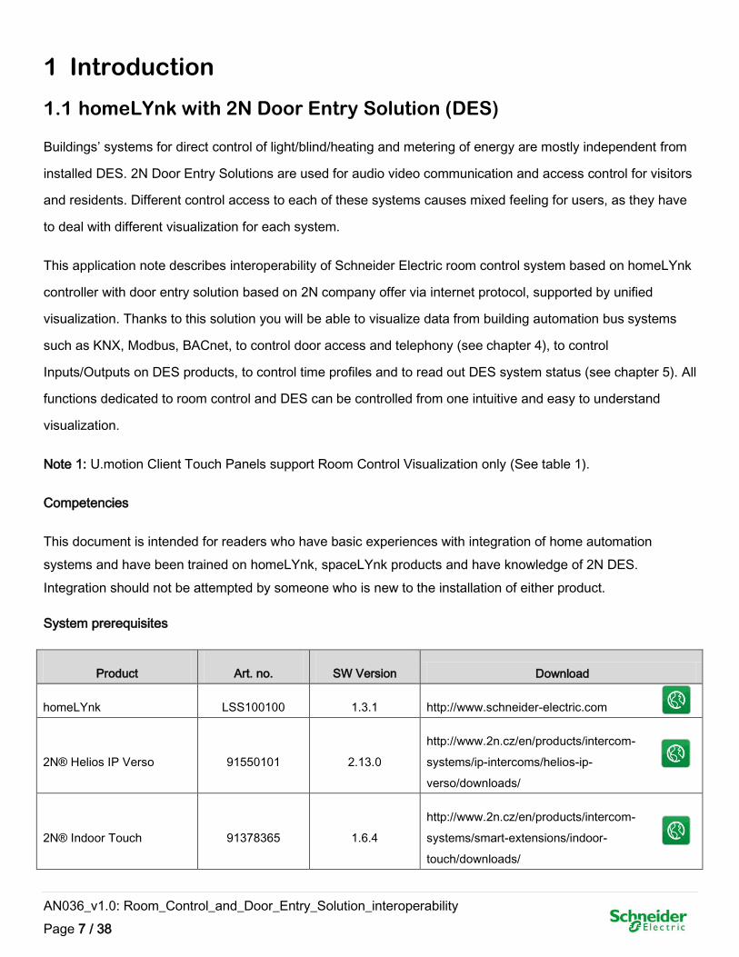
System prerequisites
Product Art. no. SW Version Download
homeLYnk LSS100100 1.3.1 http://www.schneider-electric.com
2N® Helios IP Verso 91550101 2.13.0
http://www.2n.cz/en/products/intercom-
systems/ip-intercoms/helios-ip-
verso/downloads/
2N® Indoor Touch 91378365 1.6.4
http://www.2n.cz/en/products/intercom-
systems/smart-extensions/indoor-
touch/downloads/
AN036_v1.0: Room_Control_and_Door_Entry_Solution_interoperability
Page 8 / 38
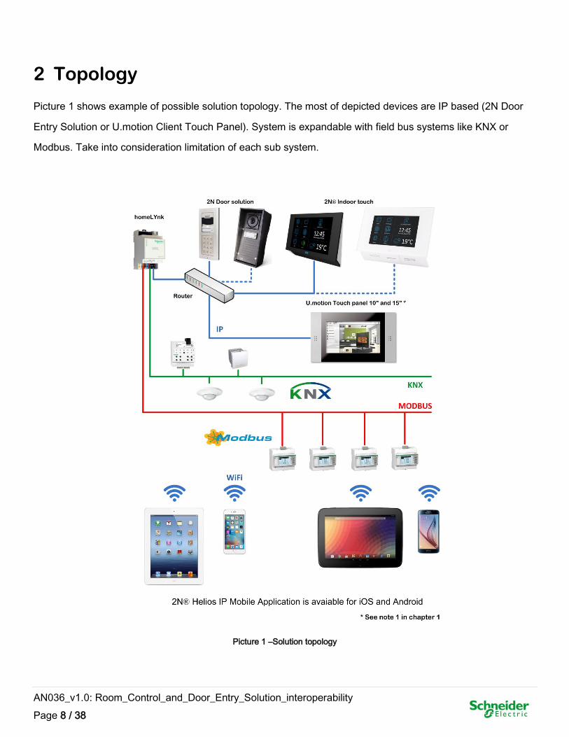
2 Topology
Picture 1 shows example of possible solution topology. The most of depicted devices are IP based (2N Door
Entry Solution or U.motion Client Touch Panel). System is expandable with field bus systems like KNX or
Modbus. Take into consideration limitation of each sub system.
Picture 1 –Solution topology
AN036_v1.0: Room_Control_and_Door_Entry_Solution_interoperability
Page 9 / 38
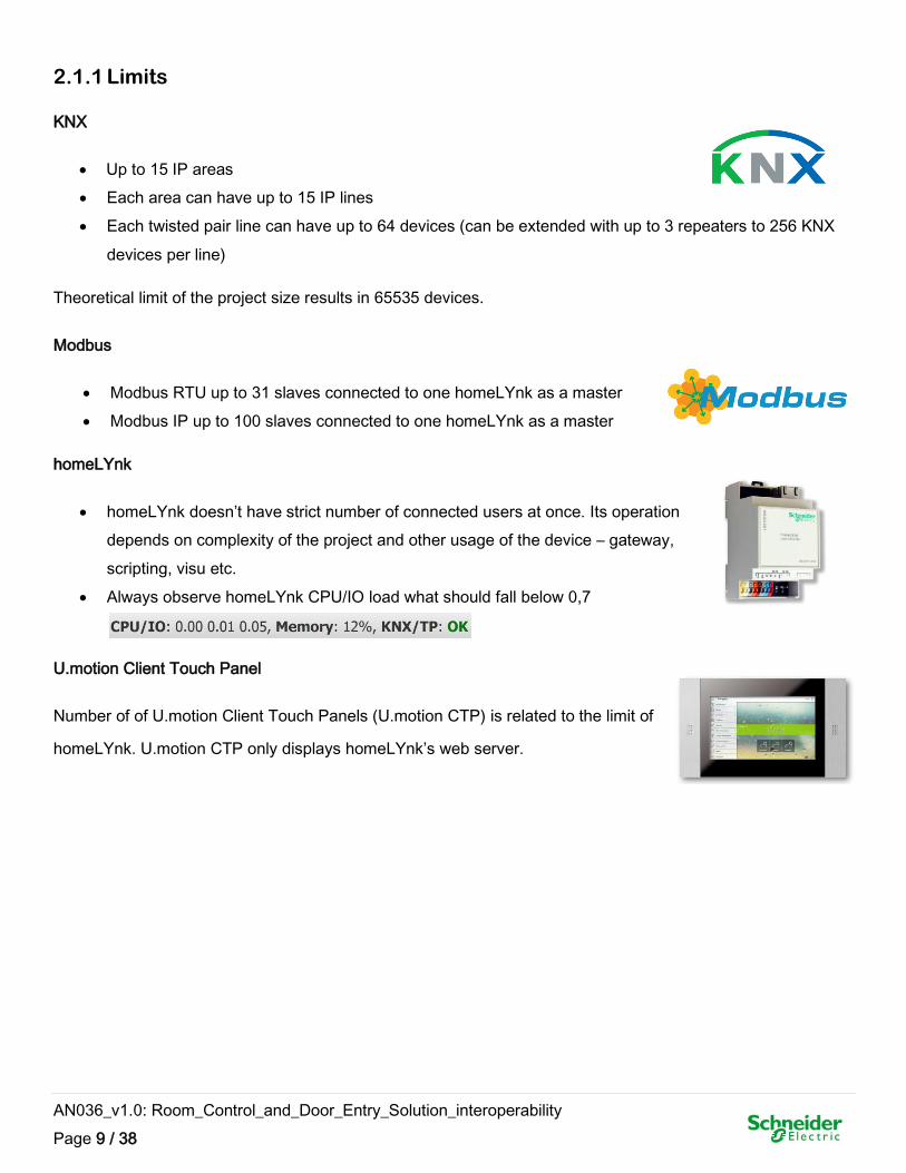
2.1.1 Limits
KNX
Up to 15 IP areas
Each area can have up to 15 IP lines
Each twisted pair line can have up to 64 devices (can be extended with up to 3 repeaters to 256 KNX
devices per line)
Theoretical limit of the project size results in 65535 devices.
Modbus
Modbus RTU up to 31 slaves connected to one homeLYnk as a master
Modbus IP up to 100 slaves connected to one homeLYnk as a master
homeLYnk
homeLYnk doesn’t have strict number of connected users at once. Its operation
depends on complexity of the project and other usage of the device – gateway,
scripting, visu etc.
Always observe homeLYnk CPU/IO load what should fall below 0,7
U.motion Client Touch Panel
Number of of U.motion Client Touch Panels (U.motion CTP) is related to the limit of
homeLYnk. U.motion CTP only displays homeLYnk’s web server.
AN036_v1.0: Room_Control_and_Door_Entry_Solution_interoperability
Page 10 / 38
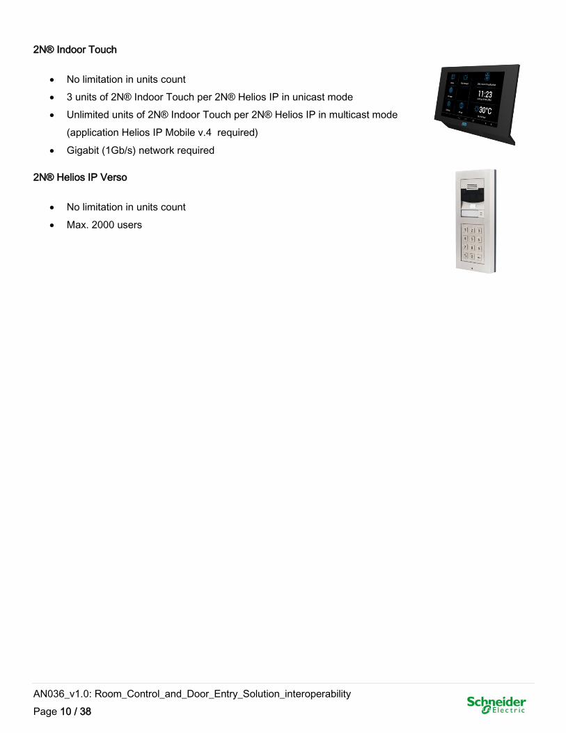
2N® Indoor Touch
No limitation in units count
3 units of 2N® Indoor Touch per 2N® Helios IP in unicast mode
Unlimited units of 2N® Indoor Touch per 2N® Helios IP in multicast mode
(application Helios IP Mobile v.4 required)
Gigabit (1Gb/s) network required
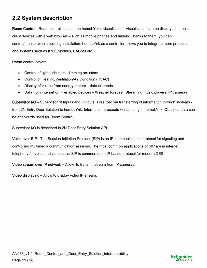
2N® Helios IP Verso
No limitation in units count
Max. 2000 users
AN036_v1.0: Room_Control_and_Door_Entry_Solution_interoperability
Page 11 / 38
2.2 System description
Room Control - Room control is based on homeLYnk’s visualization. Visualization can be displayed in most
client devices with a web browser – such as mobile phones and tablets. Thanks to them, you can
control/monitor whole building installation. homeLYnk as a controller allows you to integrate more protocols
and systems such as KNX, Modbus, BACnet etc.
Room control covers:
Control of lights, shutters, dimming actuators
Control of Heating/Ventilation/Air Condition (HVAC)
Display of values from energy meters – data or trends
Data from internet or IP enabled devices – Weather forecast, Streaming music players, IP cameras
Supervisor I/O – Supervisor of Inputs and Outputs is realized via transferring of information through systems -
from 2N Entry Door Solution to homeLYnk. Information proceeds via scripting in homeLYnk. Obtained data can
be afterwards used for Room Control.
Supervisor I/O is described in 2N Door Entry Solution API.
Voice over SIP - The Session Initiation Protocol (SIP) is an IP communications protocol for signaling and
controlling multimedia communication sessions. The most common applications of SIP are in internet
telephony for voice and video calls. SIP is common open IP based protocol for modern DES.
Video stream over IP network – Allow to transmit stream from IP cameras.
Video displaying – Allow to display video IP stream.
AN036_v1.0: Room_Control_and_Door_Entry_Solution_interoperability
Page 12 / 38
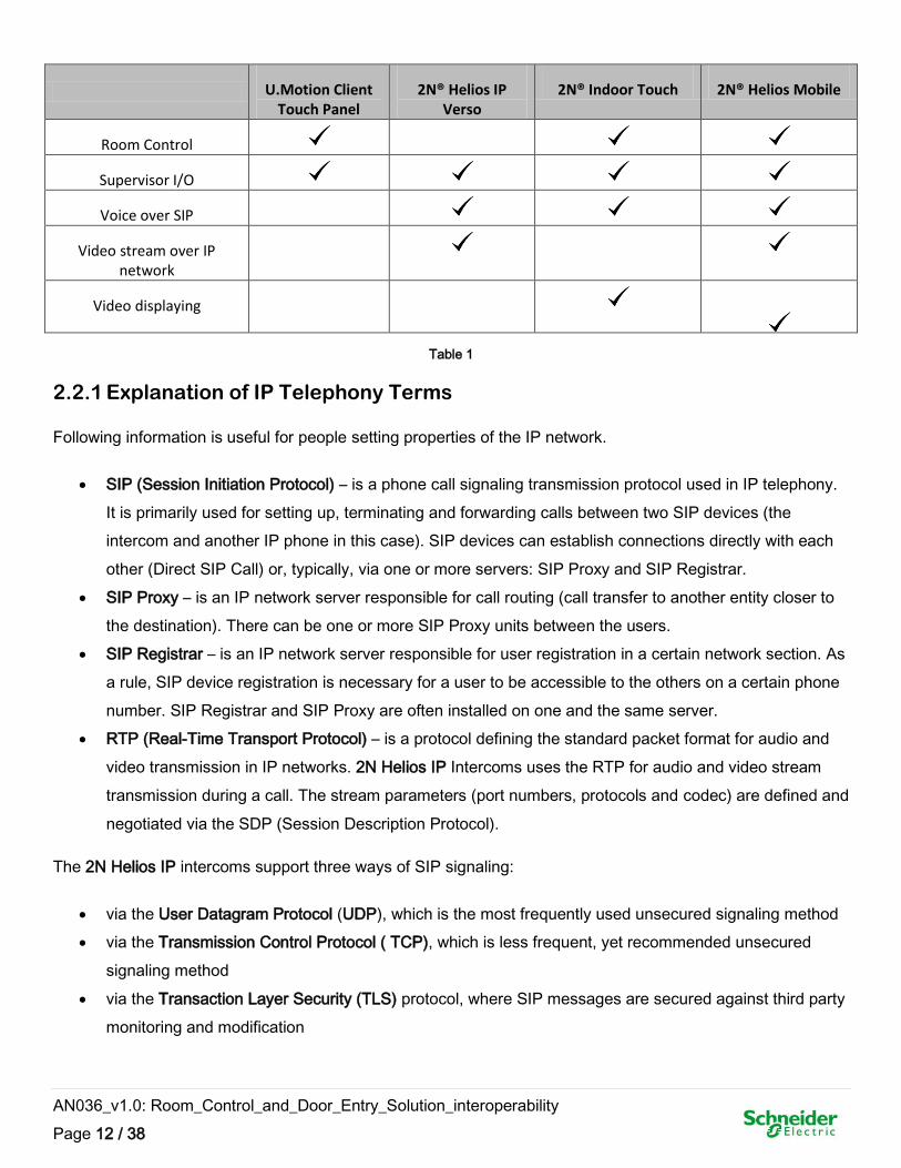
U.Motion Client Touch Panel
2N® Helios IP Verso
2N® Indoor Touch 2N® Helios Mobile
Room Control
Supervisor I/O
Voice over SIP
Video stream over IP network
Video displaying
Table 1
2.2.1 Explanation of IP Telephony Terms
Following information is useful for people setting properties of the IP network.
SIP (Session Initiation Protocol) – is a phone call signaling transmission protocol used in IP telephony.
It is primarily used for setting up, terminating and forwarding calls between two SIP devices (the
intercom and another IP phone in this case). SIP devices can establish connections directly with each
other (Direct SIP Call) or, typically, via one or more servers: SIP Proxy and SIP Registrar.
SIP Proxy – is an IP network server responsible for call routing (call transfer to another entity closer to
the destination). There can be one or more SIP Proxy units between the users.
SIP Registrar – is an IP network server responsible for user registration in a certain network section. As
a rule, SIP device registration is necessary for a user to be accessible to the others on a certain phone
number. SIP Registrar and SIP Proxy are often installed on one and the same server.
RTP (Real-Time Transport Protocol) – is a protocol defining the standard packet format for audio and
video transmission in IP networks. 2N Helios IP Intercoms uses the RTP for audio and video stream
transmission during a call. The stream parameters (port numbers, protocols and codec) are defined and
negotiated via the SDP (Session Description Protocol).
The 2N Helios IP intercoms support three ways of SIP signaling:
via the User Datagram Protocol (UDP), which is the most frequently used unsecured signaling method
via the Transmission Control Protocol ( TCP), which is less frequent, yet recommended unsecured
signaling method
via the Transaction Layer Security (TLS) protocol, where SIP messages are secured against third party
monitoring and modification
AN036_v1.0: Room_Control_and_Door_Entry_Solution_interoperability
Page 13 / 38
2.3 2N Portfolio introduction
2N IP intercom portfolio consists from different intercom units that are made to provide audio and video
communication together with access control. Wide portfolio enables to cover requirements from residential
installations through office buildings up to areas with need for anti vandal solutions.
In combination with 2N indoor answering unit 2N® Indoor Touch it offers complete solution for door
communication.
Please consider, that some solutions will need additional 2N licenses:
Advanced Integration License - Extended lock control (call activation, quick dial button activation, time
profiles for locks), picture to email, auto updates (TFTP), HTTP commands for lock control
Advanced Video License - RTSP streaming server
AN036_v1.0: Room_Control_and_Door_Entry_Solution_interoperability
Page 14 / 38
2.3.1 IP Intercoms
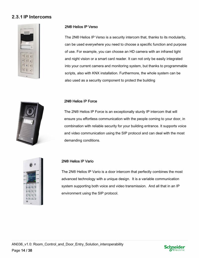
2N® Helios IP Verso
The 2N® Helios IP Verso is a security intercom that, thanks to its modularity,
can be used everywhere you need to choose a specific function and purpose
of use. For example, you can choose an HD camera with an infrared light
and night vision or a smart card reader. It can not only be easily integrated
into your current camera and monitoring system, but thanks to programmable
scripts, also with KNX installation. Furthermore, the whole system can be
also used as a security component to protect the building
2N® Helios IP Force
The 2N® Helios IP Force is an exceptionally sturdy IP intercom that will
ensure you effortless communication with the people coming to your door, in
combination with reliable security for your building entrance. It supports voice
and video communication using the SIP protocol and can deal with the most
demanding conditions.
2N® Helios IP Vario
The 2N® Helios IP Vario is a door intercom that perfectly combines the most
advanced technology with a unique design. It is a variable communication
system supporting both voice and video transmission. And all that in an IP
environment using the SIP protocol.
AN036_v1.0: Room_Control_and_Door_Entry_Solution_interoperability
Page 15 / 38
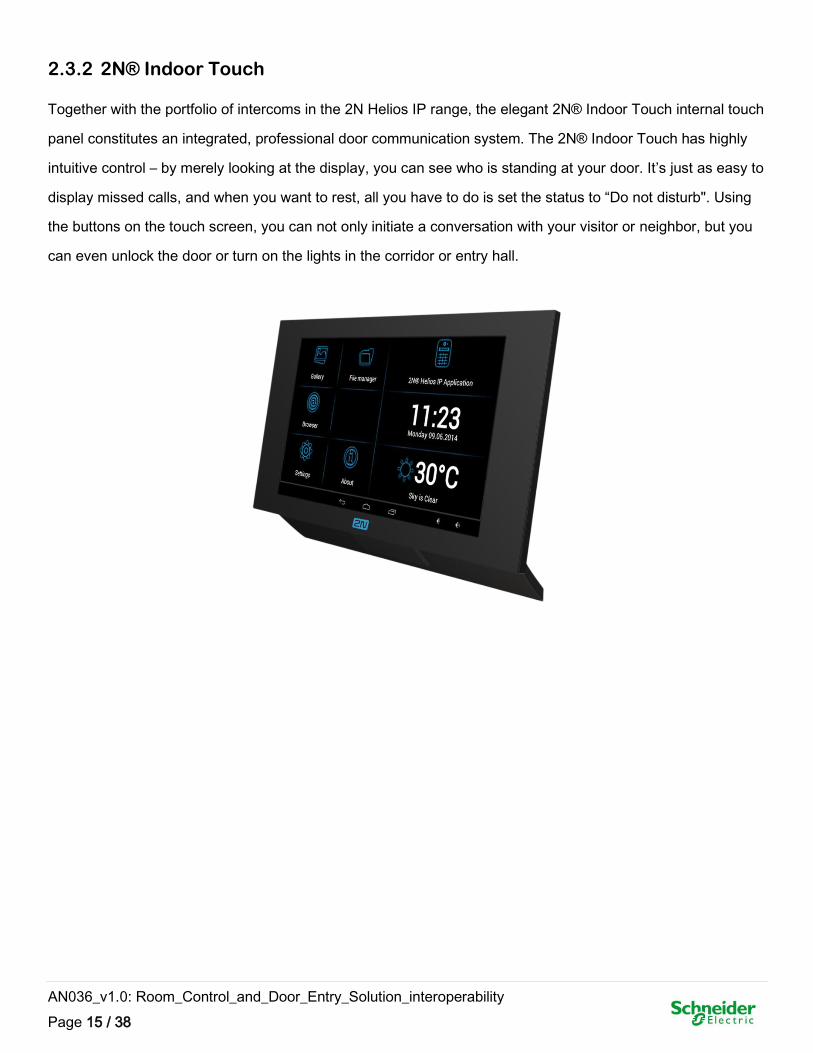
2.3.2 2N® Indoor Touch
Together with the portfolio of intercoms in the 2N Helios IP range, the elegant 2N® Indoor Touch internal touch
panel constitutes an integrated, professional door communication system. The 2N® Indoor Touch has highly
intuitive control – by merely looking at the display, you can see who is standing at your door. It’s just as easy to
display missed calls, and when you want to rest, all you have to do is set the status to “Do not disturb". Using
the buttons on the touch screen, you can not only initiate a conversation with your visitor or neighbor, but you
can even unlock the door or turn on the lights in the corridor or entry hall.
AN036_v1.0: Room_Control_and_Door_Entry_Solution_interoperability
Page 16 / 38
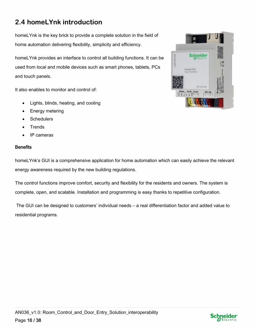
2.4 homeLYnk introduction
homeLYnk is the key brick to provide a complete solution in the field of
home automation delivering flexibility, simplicity and efficiency.
homeLYnk provides an interface to control all building functions. It can be
used from local and mobile devices such as smart phones, tablets, PCs
and touch panels.
It also enables to monitor and control of:
Lights, blinds, heating, and cooling
Energy metering
Schedulers
Trends
IP cameras
Benefits
homeLYnk’s GUI is a comprehensive application for home automation which can easily achieve the relevant
energy awareness required by the new building regulations.
The control functions improve comfort, security and flexibility for the residents and owners. The system is
complete, open, and scalable. Installation and programming is easy thanks to repetitive configuration.
The GUI can be designed to customers’ individual needs – a real differentiation factor and added value to
residential programs.
AN036_v1.0: Room_Control_and_Door_Entry_Solution_interoperability
Page 17 / 38
2.4.1 homeLYnk interfaces and usage
1. Gateway between systems – KNX, BACnet, Modbus, IP world, HVAC, etc.
2. Visualization on PC/Tablets and Smart phones (via web server)
3. Logic controller (LUA scripting, Logic, Date and time, …)
4. KNX commissioning, KNX Line coupler both for Twisted Pair (TP)/IP
5. Build-in web server no additional software needed
KNX
KNX is a standardized, worldwide used (EN 50090, ISO/IEC 14543), OSI-
based network communications protocol for intelligent buildings. The KNX
standard is administered by the KNX Association
homeLYnk is able to operate with TP BUS and IP telegrams for big installations
BACnet
BACnet is a communications protocol for building automation
and control networks. It is an ASHRAE, ANSI, and ISO 16484-5
standard protocol
BACnet was designed to allow communication of building automation and control systems for
applications such as heating, ventilating, and air-conditioning control, lighting control, access
control, and fire detection systems and their associated equipment. Proper communication between
building automation devices is critical for maximizing building energy efficiency, indoor air quality,
and other aspects of "green" buildings
homeLYnk serves like a BACnet server with up 150 BACnet points
Modbus
Modbus is a serial communications protocol originally published by
Modicon (now Schneider Electric) in 1979 for use with its
programmable logic controllers (PLCs). Simple and robust, it has
since become a de facto industrial standard communication protocol,
and it is now a commonly available for connecting industrial electronic devices such as power
meters, RTCU, HVAC devices etc.
homeLYnk serves either as a Modbus slave or master
AN036_v1.0: Room_Control_and_Door_Entry_Solution_interoperability
Page 18 / 38
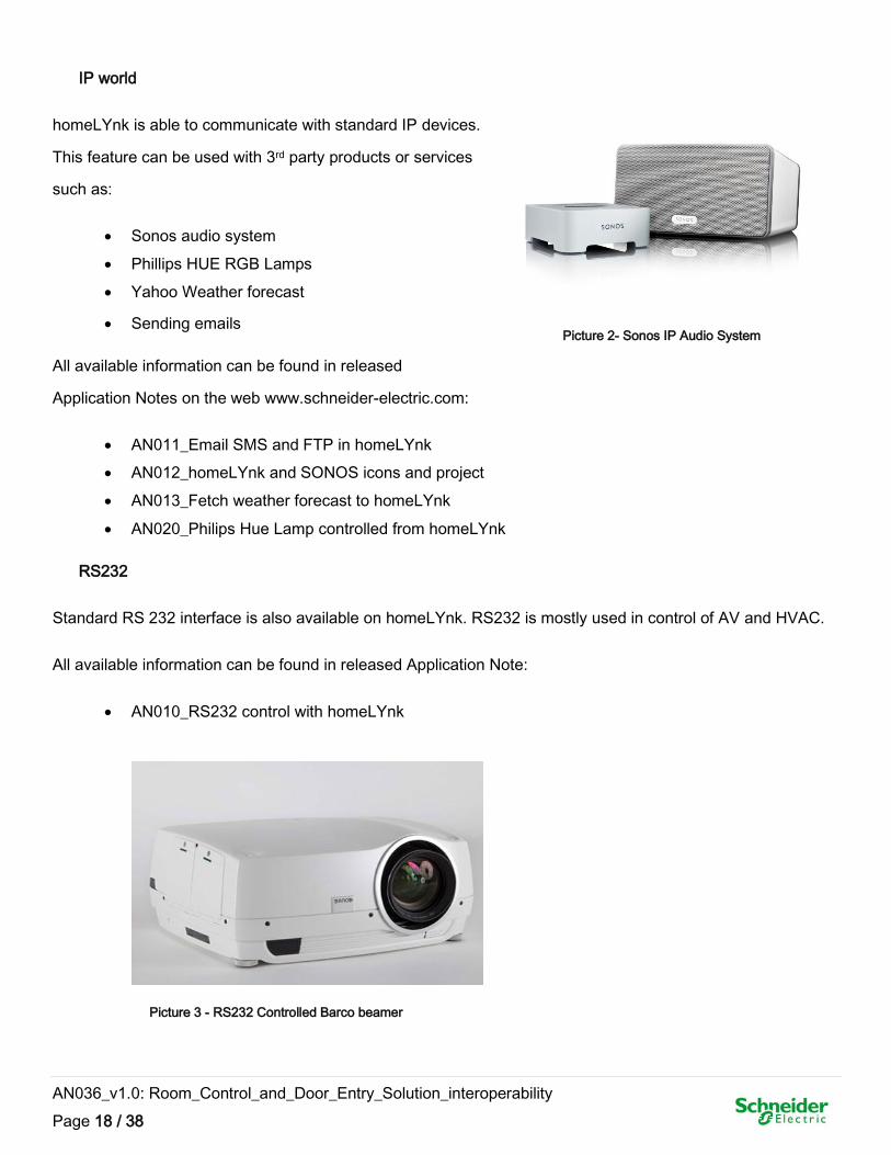
IP world
homeLYnk is able to communicate with standard IP devices.
This feature can be used with 3rd party products or services
such as:
Sonos audio system
Phillips HUE RGB Lamps
Yahoo Weather forecast
Sending emails
All available information can be found in released
Application Notes on the web www.schneider-electric.com:
AN011_Email SMS and FTP in homeLYnk
AN012_homeLYnk and SONOS icons and project
AN013_Fetch weather forecast to homeLYnk
AN020_Philips Hue Lamp controlled from homeLYnk
RS232
Standard RS 232 interface is also available on homeLYnk. RS232 is mostly used in control of AV and HVAC.
All available information can be found in released Application Note:
AN010_RS232 control with homeLYnk
Picture 2- Sonos IP Audio System
Picture 3 - RS232 Controlled Barco beamer
AN036_v1.0: Room_Control_and_Door_Entry_Solution_interoperability
Page 19 / 38
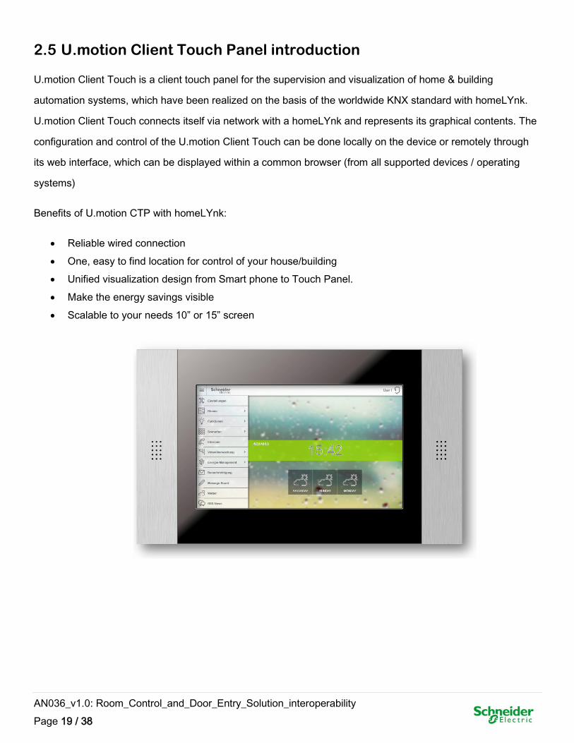
2.5 U.motion Client Touch Panel introduction
U.motion Client Touch is a client touch panel for the supervision and visualization of home & building
automation systems, which have been realized on the basis of the worldwide KNX standard with homeLYnk.
U.motion Client Touch connects itself via network with a homeLYnk and represents its graphical contents. The
configuration and control of the U.motion Client Touch can be done locally on the device or remotely through
its web interface, which can be displayed within a common browser (from all supported devices / operating
systems)
Benefits of U.motion CTP with homeLYnk:
Reliable wired connection
One, easy to find location for control of your house/building
Unified visualization design from Smart phone to Touch Panel.
Make the energy savings visible
Scalable to your needs 10” or 15” screen
AN036_v1.0: Room_Control_and_Door_Entry_Solution_interoperability
Page 20 / 38
3 SW upgrade
We recommend firmware upgrade to latest firmware version in all devices to
avoid any operational issues.
3.1 Upgrade of homeLYnk
For homeLYnk upgrade we recommend to read the
AN028_homeLYnk_ugrade_procedure – homeLYnk upgrade procedure
downloadable from www.schneider-electric.com
Note: Please consider possible backward compatibility issues mentioned in above AN.
3.2 Upgrade of 2N devices
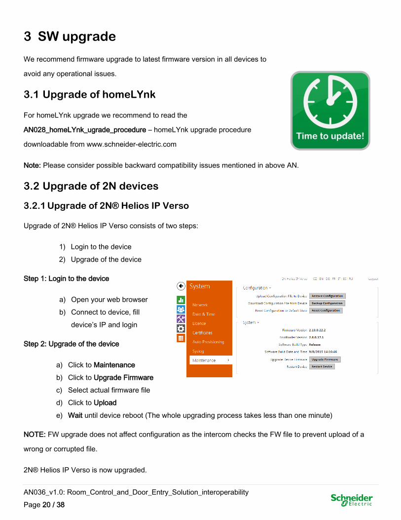
3.2.1 Upgrade of 2N® Helios IP Verso
Upgrade of 2N® Helios IP Verso consists of two steps:
1) Login to the device
2) Upgrade of the device
Step 1: Login to the device
a) Open your web browser
b) Connect to device, fill
device’s IP and login
Step 2: Upgrade of the device
a) Click to Maintenance
b) Click to Upgrade Firmware
c) Select actual firmware file
d) Click to Upload
e) Wait until device reboot (The whole upgrading process takes less than one minute)
NOTE: FW upgrade does not affect configuration as the intercom checks the FW file to prevent upload of a
wrong or corrupted file.
2N® Helios IP Verso is now upgraded.
AN036_v1.0: Room_Control_and_Door_Entry_Solution_interoperability
Page 21 / 38
3.2.2 Upgrade of 2N® Indoor Touch
2N® Indoor Touch can be upgraded via an SD card only. The firmware packet always includes the latest OS
version, a Launcher and 2N® Helios IP Mobile application.
Upgrade of 2N® Indoor Touch consists of two steps:
1) Upload firmware to SD card
2) Reset the device
Step 1: Upload firmware to SD card
a) Get a microSD (SDHC) card with maximum capacity of 16 GB and with the FAT32 file system
b) Unpack and save the *.ZIP download (actual firmware package) into the SD card root directory.
c) Insert the SD card in the SD card slot on the left side of 2N® Indoor Touch
Step 2: Reset the device
a) Press the backside Reset button shortly OR click the Reboot button in the configuration section
of the introductory screen
b) Having detected correct firmware files, 2N® Indoor Touch invites you to confirm upgrade via a
touch screen. The upgrade process is also indicated by an RGB LED on the device front
c) Having completed upgrade, remove the SD card and click on the display to restart the system.
Caution:
The device upgrade takes approximately 10 minutes or more.
The first startup after successful upgrade may take a few minutes.
The factory values can be reset automatically in some upgrade types.
2N® Indoor Touch is now upgraded.
AN036_v1.0: Room_Control_and_Door_Entry_Solution_interoperability
Page 22 / 38
4 Elementary configuration
This chapter describes configuration of homeLYnk, U.motion and 2N devices for their elementary
interoperability. At the end of this chapter you will be able to call from Helios to Indoor Touch and vice versa
and have consistent visualization displayed on Indoor Touch for SIP telephony and Room Control.
4.1 Configuration of homeLYnk
Before you start with configuration of homeLYnk related to 2N, check that following steps were done:
Set of IP address
Set of IP/TP mode
Import of KNX objects
File archive delivered with this Application Note contains complete Demo project, which can be imported. This
Demo project is based on virtual KNX addresses and serves as an illustration of graphical interface and
sample of 2N API interoperability script.
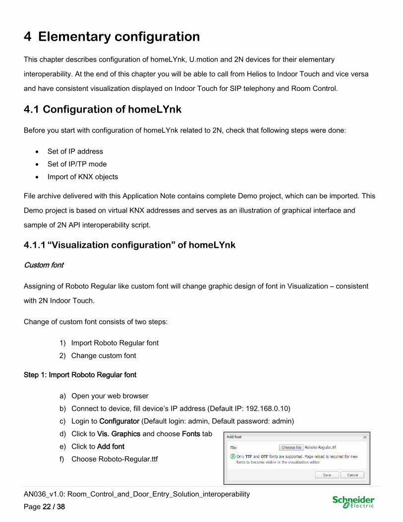
4.1.1 “Visualization configuration” of homeLYnk
Custom font
Assigning of Roboto Regular like custom font will change graphic design of font in Visualization – consistent
with 2N Indoor Touch.
Change of custom font consists of two steps:
1) Import Roboto Regular font
2) Change custom font
Step 1: Import Roboto Regular font
a) Open your web browser
b) Connect to device, fill device’s IP address (Default IP: 192.168.0.10)
c) Login to Configurator (Default login: admin, Default password: admin)
d) Click to Vis. Graphics and choose Fonts tab
e) Click to Add font
f) Choose Roboto-Regular.ttf
AN036_v1.0: Room_Control_and_Door_Entry_Solution_interoperability
Page 23 / 38
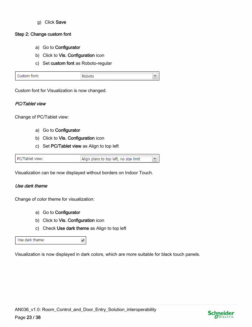
g) Click Save
Step 2: Change custom font
a) Go to Configurator
b) Click to Vis. Configuration icon
c) Set custom font as Roboto-regular
Custom font for Visualization is now changed.
PC/Tablet view
Change of PC/Tablet view:
a) Go to Configurator
b) Click to Vis. Configuration icon
c) Set PC/Tablet view as Align to top left
Visualization can be now displayed without borders on Indoor Touch.
Use dark theme
Change of color theme for visualization:
a) Go to Configurator
b) Click to Vis. Configuration icon
c) Check Use dark theme as Align to top left
Visualization is now displayed in dark colors, which are more suitable for black touch panels.
AN036_v1.0: Room_Control_and_Door_Entry_Solution_interoperability
Page 24 / 38
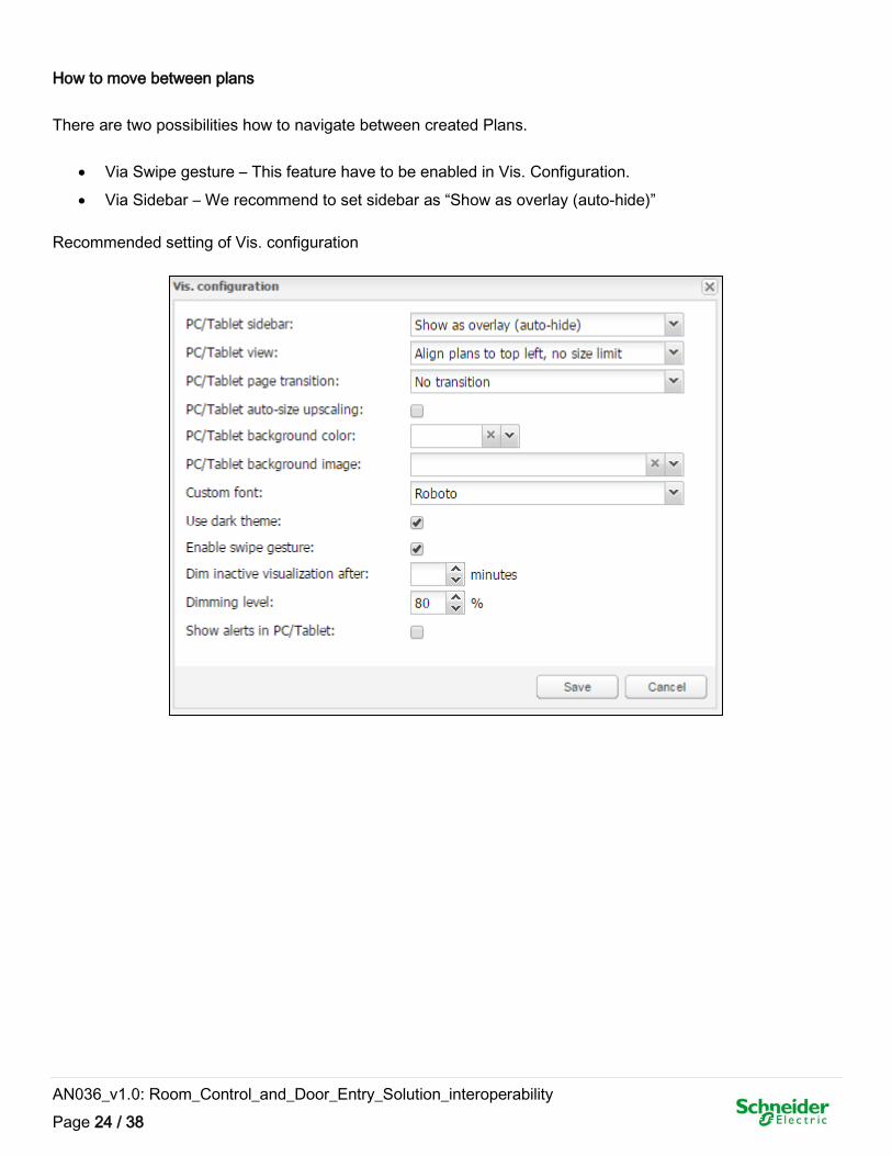
How to move between plans
There are two possibilities how to navigate between created Plans.
Via Swipe gesture – This feature have to be enabled in Vis. Configuration.
Via Sidebar – We recommend to set sidebar as “Show as overlay (auto-hide)”
Recommended setting of Vis. configuration
AN036_v1.0: Room_Control_and_Door_Entry_Solution_interoperability
Page 25 / 38
4.1.2 Import of SE pre-made 2N graphic for visualization
Pre-made SE 2N graphic packages are useful for visualization, which will be displayed on 2N® Indoor Touch.
Pre-made SE graphic and build-in 2N® Indoor Touch graphic have matching design.
Import of pre-made SE 2N graphic consists of two steps:
1) Import of Icons
2) Import of Images
Step 1: Import of Icons
a) Open your web browser
b) Connect to device, fill device’s IP address (Default IP: 192.168.0.10)
c) Login to Configurator (Default login: admin, Default password: admin)
d) Click to Vis. Graphics
e) Click to Icons tab
f) Click to Add icons
g) Choose Icons_BB_Graphic_pack.zip
h) Click Save
Step 2: Import of Images
a) Go to Configurator
b) Click to Vis. Graphics
c) Click to Images / Backgrounds tab
d) Click to Add images
e) Choose Images_BB_Graphic_pack.zip
f) Click Save
SE 2N graphic is now available in the device.
AN036_v1.0: Room_Control_and_Door_Entry_Solution_interoperability
Page 26 / 38
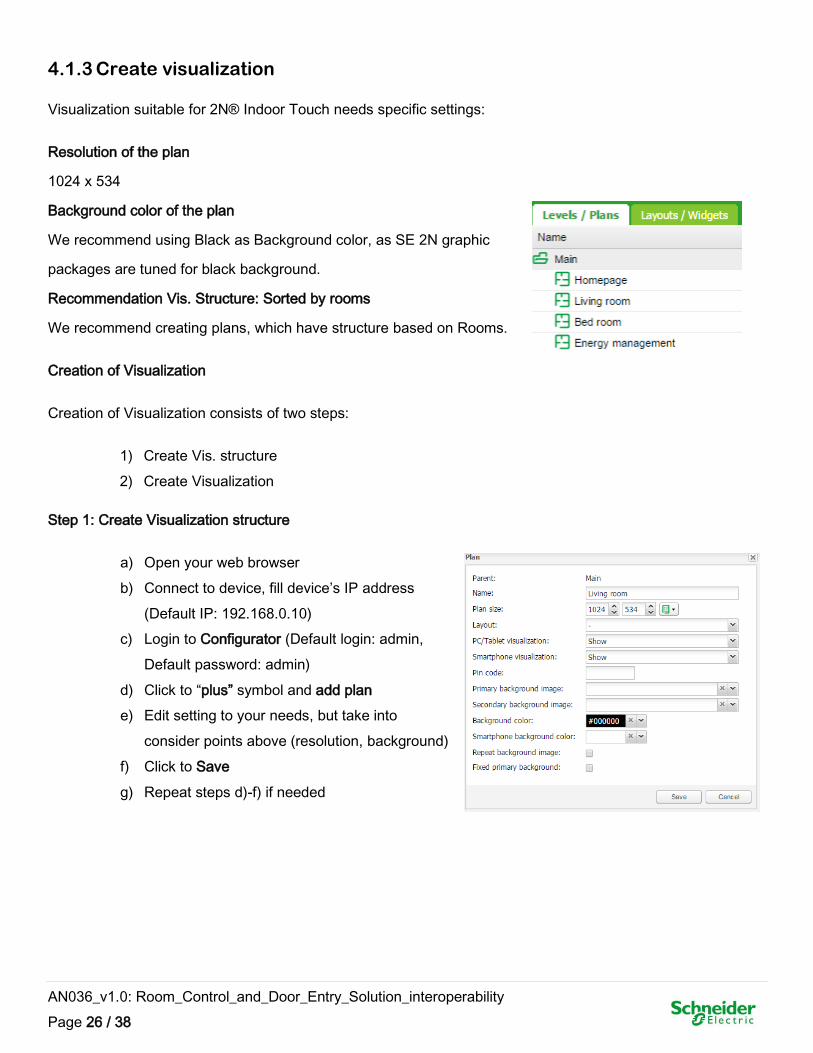
4.1.3 Create visualization
Visualization suitable for 2N® Indoor Touch needs specific settings:
Resolution of the plan
1024 x 534
Background color of the plan
We recommend using Black as Background color, as SE 2N graphic
packages are tuned for black background.
Recommendation Vis. Structure: Sorted by rooms
We recommend creating plans, which have structure based on Rooms.
Creation of Visualization
Creation of Visualization consists of two steps:
1) Create Vis. structure
2) Create Visualization
Step 1: Create Visualization structure
a) Open your web browser
b) Connect to device, fill device’s IP address
(Default IP: 192.168.0.10)
c) Login to Configurator (Default login: admin,
Default password: admin)
d) Click to “plus” symbol and add plan
e) Edit setting to your needs, but take into
consider points above (resolution, background)
f) Click to Save
g) Repeat steps d)-f) if needed
AN036_v1.0: Room_Control_and_Door_Entry_Solution_interoperability
Page 27 / 38
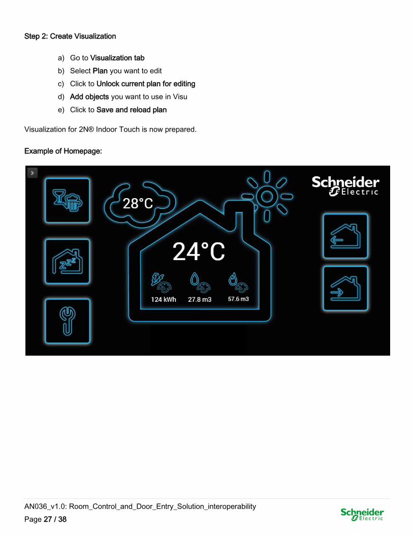
Step 2: Create Visualization
a) Go to Visualization tab
b) Select Plan you want to edit
c) Click to Unlock current plan for editing
d) Add objects you want to use in Visu
e) Click to Save and reload plan
Visualization for 2N® Indoor Touch is now prepared.
Example of Homepage:
AN036_v1.0: Room_Control_and_Door_Entry_Solution_interoperability
Page 28 / 38
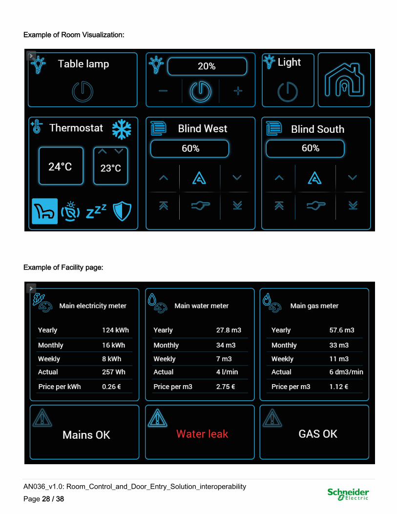
Example of Room Visualization:
Example of Facility page:
AN036_v1.0: Room_Control_and_Door_Entry_Solution_interoperability
Page 29 / 38
4.2 Configuration of 2N Devices
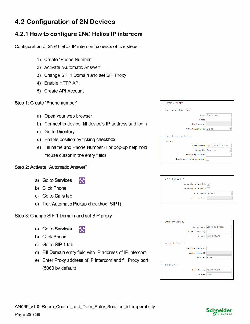
4.2.1 How to configure 2N® Helios IP intercom
Configuration of 2N® Helios IP intercom consists of five steps:
1) Create “Phone Number”
2) Activate “Automatic Answer”
3) Change SIP 1 Domain and set SIP Proxy
4) Enable HTTP API
5) Create API Account
Step 1: Create “Phone number”
a) Open your web browser
b) Connect to device, fill device’s IP address and login
c) Go to Directory
d) Enable position by ticking checkbox
e) Fill name and Phone Number (For pop-up help hold
mouse cursor in the entry field)
Step 2: Activate “Automatic Answer”
a) Go to Services
b) Click Phone
c) Go to Calls tab
d) Tick Automatic Pickup checkbox (SIP1)
Step 3: Change SIP 1 Domain and set SIP proxy
a) Go to Services
b) Click Phone
c) Go to SIP 1 tab
d) Fill Domain entry field with IP address of IP intercom
e) Enter Proxy address of IP intercom and fill Proxy port
(5060 by default)
AN036_v1.0: Room_Control_and_Door_Entry_Solution_interoperability
Page 30 / 38
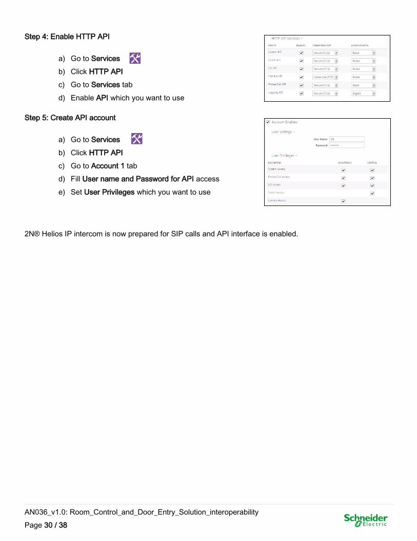
Step 4: Enable HTTP API
a) Go to Services
b) Click HTTP API
c) Go to Services tab
d) Enable API which you want to use
Step 5: Create API account
a) Go to Services
b) Click HTTP API
c) Go to Account 1 tab
d) Fill User name and Password for API access
e) Set User Privileges which you want to use
2N® Helios IP intercom is now prepared for SIP calls and API interface is enabled.
AN036_v1.0: Room_Control_and_Door_Entry_Solution_interoperability
Page 31 / 38
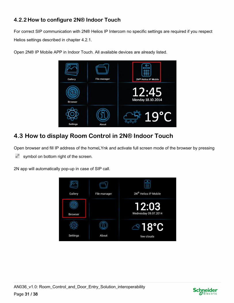
4.2.2 How to configure 2N® Indoor Touch
For correct SIP communication with 2N® Helios IP Intercom no specific settings are required if you respect
Helios settings described in chapter 4.2.1.
Open 2N® IP Mobile APP in Indoor Touch. All available devices are already listed.
4.3 How to display Room Control in 2N® Indoor Touch
Open browser and fill IP address of the homeLYnk and activate full screen mode of the browser by pressing
symbol on bottom right of the screen.
2N app will automatically pop-up in case of SIP call.
AN036_v1.0: Room_Control_and_Door_Entry_Solution_interoperability
Page 32 / 38
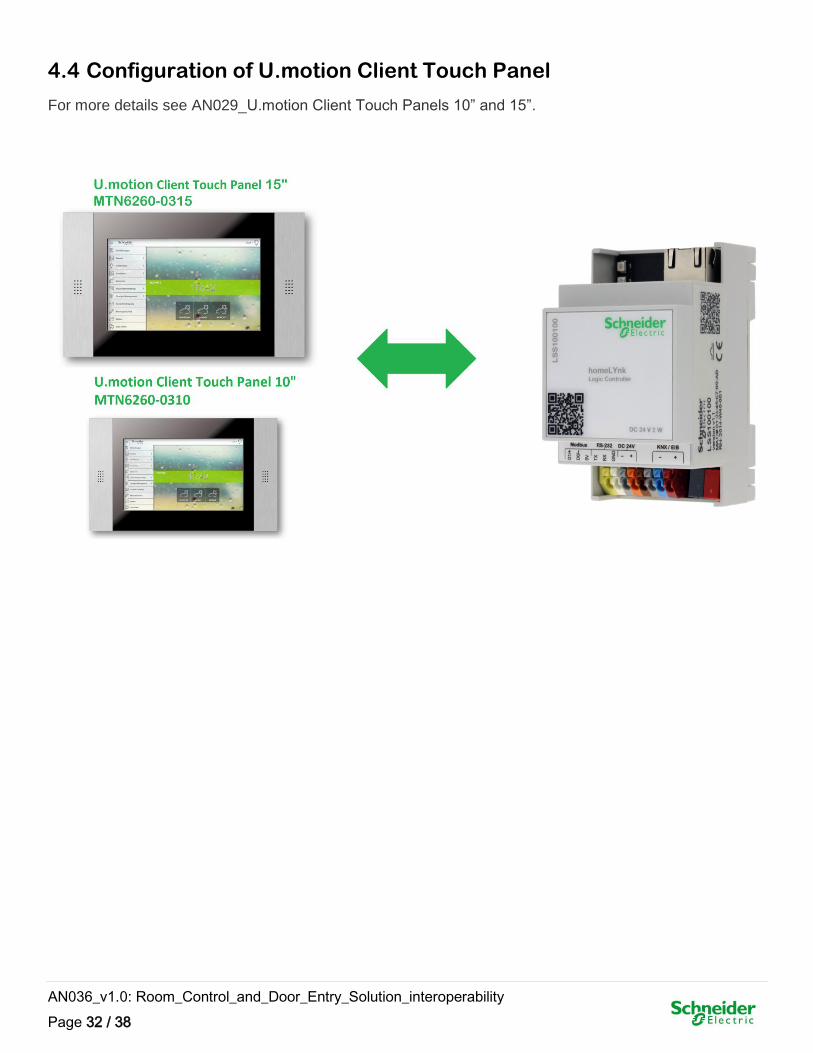
4.4 Configuration of U.motion Client Touch Panel
For more details see AN029_U.motion Client Touch Panels 10” and 15”.
AN036_v1.0: Room_Control_and_Door_Entry_Solution_interoperability
Page 33 / 38
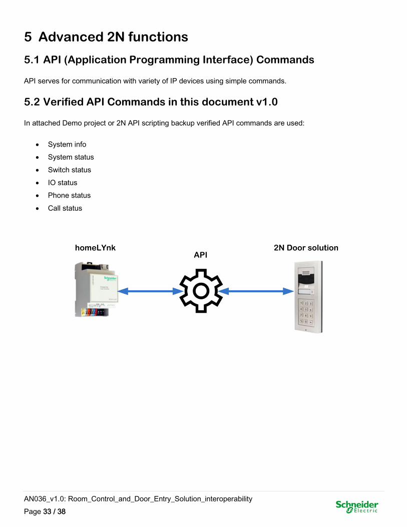
5 Advanced 2N functions
5.1 API (Application Programming Interface) Commands
API serves for communication with variety of IP devices using simple commands.
5.2 Verified API Commands in this document v1.0
In attached Demo project or 2N API scripting backup verified API commands are used:
System info
System status
Switch status
IO status
Phone status
Call status
AN036_v1.0: Room_Control_and_Door_Entry_Solution_interoperability
Page 34 / 38
5.3 How to use API Commands
All API commands scripts are attached in “2N API scripting backup”.
They are deployed in following script tabs:
Event-based (script “2N API Trigger”)
User libraries (script “user.2NAPI”)
API configuration consists of four steps:
1) Restoring scripts
2) Setting of user libraries script
3) Editing of “2N API Trigger” script
4) Creating objects for visualization
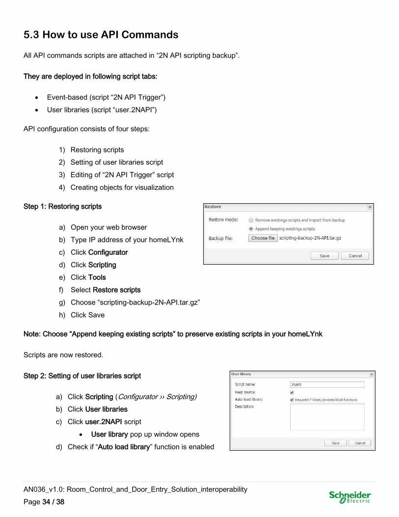
Step 1: Restoring scripts
a) Open your web browser
b) Type IP address of your homeLYnk
c) Click Configurator
d) Click Scripting
e) Click Tools
f) Select Restore scripts
g) Choose “scripting-backup-2N-API.tar.gz”
h) Click Save
Note: Choose “Append keeping existing scripts” to preserve existing scripts in your homeLYnk
Scripts are now restored.
Step 2: Setting of user libraries script
a) Click Scripting (Configurator ›› Scripting)
b) Click User libraries
c) Click user.2NAPI script
User library pop up window opens
d) Check if “Auto load library” function is enabled
AN036_v1.0: Room_Control_and_Door_Entry_Solution_interoperability
Page 35 / 38
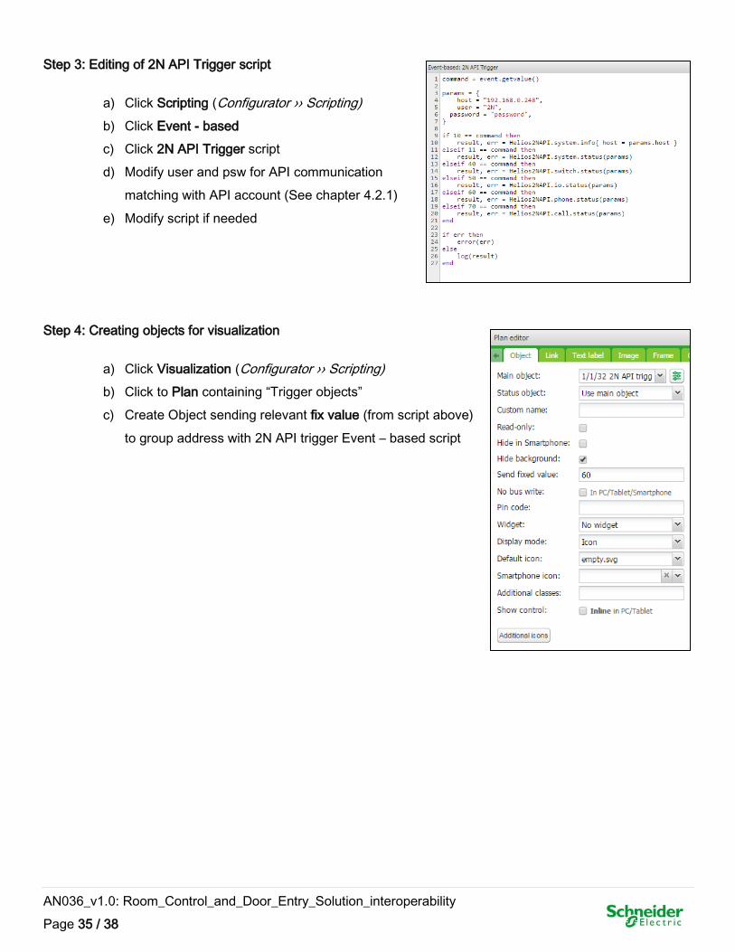
Step 3: Editing of 2N API Trigger script
a) Click Scripting (Configurator ›› Scripting)
b) Click Event - based
c) Click 2N API Trigger script
d) Modify user and psw for API communication
matching with API account (See chapter 4.2.1)
e) Modify script if needed
Step 4: Creating objects for visualization
a) Click Visualization (Configurator ›› Scripting)
b) Click to Plan containing “Trigger objects”
c) Create Object sending relevant fix value (from script above)
to group address with 2N API trigger Event – based script
AN036_v1.0: Room_Control_and_Door_Entry_Solution_interoperability
Page 36 / 38
5.3.1 Available API Commands for commissioning
system.restart – tool for restart system remotely
Use case: Remote restart of system especially in case of nonstandard behavior of IP intercom
switch.status – status of relays built-in in the IP intercom
Use Case: Check proper response of relays in the IP intercom
switch.ctrl - control of relays built-in in the IP intercom
Use case: Check proper function of relays by switching them ON/OFF
io.status – status of built-in digital inputs/outputs
Use case: Check proper function of digital I/O
io.ctrl – control of built-in digital inputs/outputs
Use case: Check proper function of digital I/O
call.dial – call SIP number XXX
Use case: Check proper function of SIP telephony by dialing SIP number
call.answer – answer SIP call
Use case: Check proper function of SIP telephony by establish SIP session
call.hangup – end SIP call
Use case: Check possibility to end ongoing SIP session
AN036_v1.0: Room_Control_and_Door_Entry_Solution_interoperability
Page 37 / 38
5.3.2 Available API Commands for Facility manager
system.status – [systemTime][upTime]
Use case: Get knowledge of real system time and uptime of IP intercom
switch.status – status of relays built-in in the IP intercom
Use Case: Check status and response of IP intercom relays
switch.ctrl - control of relays built-in in the IP intercom
Use case: Remote control of relays build-in in the IP intercom
io.status – status of built-in digital inputs/outputs
Use case: Check actual status of digital I/O
io.ctrl – control of built-in digitail inputs/outputs
Use case: Remote control of build-in I/O
call.dial – call SIP number XXX
Use case: Dial SIP number
call.answer – answer SIP call
Use case: Establish SIP Session by answering incoming call
call.hangup – end SIP call
Use case: End SIP Session by hangup proceeding call
AN036_v1.0: Room_Control_and_Door_Entry_Solution_interoperability
Page 38 / 38
6 Appendix
6.1 Glossary
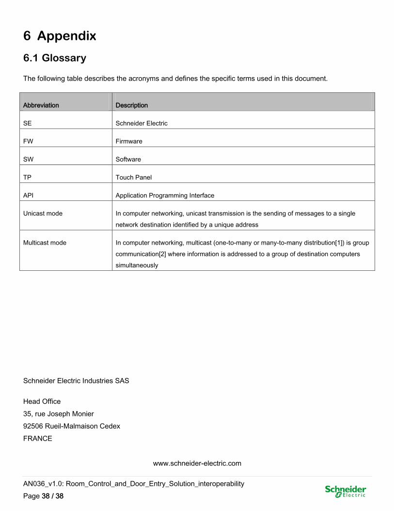
The following table describes the acronyms and defines the specific terms used in this document.
Abbreviation Description
SE Schneider Electric
FW Firmware
SW Software
TP Touch Panel
API Application Programming Interface
Unicast mode In computer networking, unicast transmission is the sending of messages to a single
network destination identified by a unique address
Multicast mode In computer networking, multicast (one-to-many or many-to-many distribution[1]) is group
communication[2] where information is addressed to a group of destination computers
simultaneously
Schneider Electric Industries SAS
Head Office
35, rue Joseph Monier
92506 Rueil-Malmaison Cedex
FRANCE
www.schneider-electric.com


![[en]=> (LV-CAN200) - Teltonika Wiki](https://static.fdokumen.com/doc/165x107/63348b9f4e43a4bcd80d4495/en-lv-can200-teltonika-wiki.jpg)