Understanding Building Information Modeling (BIM) Interoperability
13
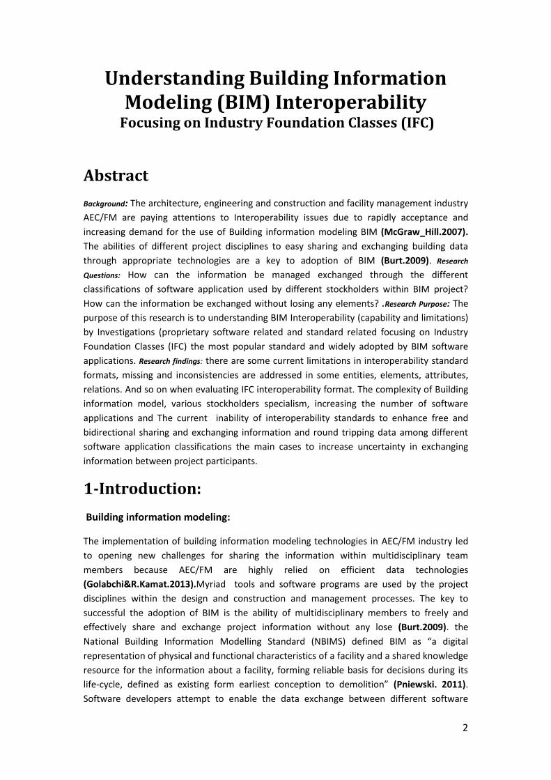
Understanding Building Information Modeling (BIM) Interoperability Focusing on Industry Foundation Classes (IFC) The University of Salford -School of Build Environment Student name: Sara Khuder Hussiain Role number: @00341770 Model name: Building Information Modeling (BIM) theory and practice Study program: Msc Building Information Modeling (BIM) and integrated design Date: 7/January /2014 2014 2014
Transcript of Understanding Building Information Modeling (BIM) Interoperability
Understanding Building Information Modeling (BIM) Interoperability
Focusing on Industry Foundation Classes (IFC)
The University of Salford -School of Build Environment
Student name: Sara Khuder Hussiain Role number: @00341770 Model name: Building Information Modeling (BIM) theory and practice Study program: Msc Building Information Modeling (BIM) and integrated design Date: 7/January /2014
2014
2014
2
Understanding Building Information Modeling (BIM) Interoperability
Focusing on Industry Foundation Classes (IFC)
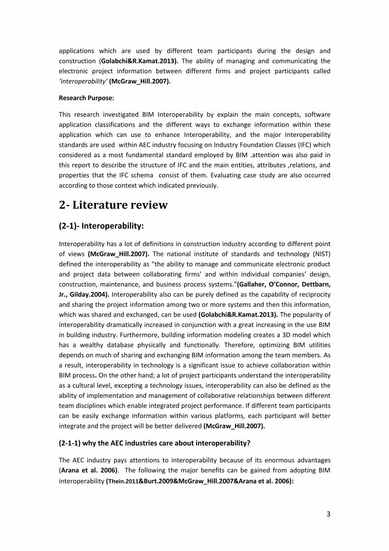
Abstract
Background: The architecture, engineering and construction and facility management industry
AEC/FM are paying attentions to Interoperability issues due to rapidly acceptance and
increasing demand for the use of Building information modeling BIM (McGraw_Hill.2007).
The abilities of different project disciplines to easy sharing and exchanging building data
through appropriate technologies are a key to adoption of BIM (Burt.2009). Research
Questions: How can the information be managed exchanged through the different
classifications of software application used by different stockholders within BIM project?
How can the information be exchanged without losing any elements? .Research Purpose: The
purpose of this research is to understanding BIM Interoperability (capability and limitations)
by Investigations (proprietary software related and standard related focusing on Industry
Foundation Classes (IFC) the most popular standard and widely adopted by BIM software
applications. Research findings: there are some current limitations in interoperability standard
formats, missing and inconsistencies are addressed in some entities, elements, attributes,
relations. And so on when evaluating IFC interoperability format. The complexity of Building
information model, various stockholders specialism, increasing the number of software
applications and The current inability of interoperability standards to enhance free and
bidirectional sharing and exchanging information and round tripping data among different
software application classifications the main cases to increase uncertainty in exchanging
information between project participants.
1-Introduction:
Building information modeling:
The implementation of building information modeling technologies in AEC/FM industry led
to opening new challenges for sharing the information within multidisciplinary team
members because AEC/FM are highly relied on efficient data technologies
(Golabchi&R.Kamat.2013).Myriad tools and software programs are used by the project
disciplines within the design and construction and management processes. The key to
successful the adoption of BIM is the ability of multidisciplinary members to freely and
effectively share and exchange project information without any lose (Burt.2009). the
National Building Information Modelling Standard (NBIMS) defined BIM as “a digital
representation of physical and functional characteristics of a facility and a shared knowledge
resource for the information about a facility, forming reliable basis for decisions during its
life-cycle, defined as existing form earliest conception to demolition” (Pniewski. 2011).
Software developers attempt to enable the data exchange between different software
3
applications which are used by different team participants during the design and
construction (Golabchi&R.Kamat.2013). The ability of managing and communicating the
electronic project information between different firms and project participants called
‘interoperability’ (McGraw_Hill.2007).
Research Purpose:
This research investigated BIM Interoperability by explain the main concepts, software
application classifications and the different ways to exchange information within these
application which can use to enhance Interoperability, and the major Interoperability
standards are used within AEC industry focusing on Industry Foundation Classes (IFC) which
considered as a most fundamental standard employed by BIM .attention was also paid in
this report to describe the structure of IFC and the main entities, attributes ,relations, and
properties that the IFC schema consist of them. Evaluating case study are also occurred
according to those context which indicated previously.
2- Literature review
(2-1)- Interoperability:
Interoperability has a lot of definitions in construction industry according to different point
of views (McGraw_Hill.2007). The national institute of standards and technology (NIST)
defined the interoperability as “the ability to manage and communicate electronic product
and project data between collaborating firms’ and within individual companies’ design,
construction, maintenance, and business process systems.”(Gallaher, O’Connor, Dettbarn,
Jr., Gilday.2004). Interoperability also can be purely defined as the capability of reciprocity
and sharing the project information among two or more systems and then this information,
which was shared and exchanged, can be used (Golabchi&R.Kamat.2013). The popularity of
interoperability dramatically increased in conjunction with a great increasing in the use BIM
in building industry. Furthermore, building information modeling creates a 3D model which
has a wealthy database physically and functionally. Therefore, optimizing BIM utilities
depends on much of sharing and exchanging BIM information among the team members. As
a result, interoperability in technology is a significant issue to achieve collaboration within
BIM process. On the other hand; a lot of project participants understand the interoperability
as a cultural level, excepting a technology issues, interoperability can also be defined as the
ability of implementation and management of collaborative relationships between different
team disciplines which enable integrated project performance. If different team participants
can be easily exchange information within various platforms, each participant will better
integrate and the project will be better delivered (McGraw_Hill.2007).
(2-1-1) why the AEC industries care about interoperability?
The AEC industry pays attentions to interoperability because of its enormous advantages
(Arana et al. 2006). The following the major benefits can be gained from adopting BIM
interoperability (Thein.2011&Burt.2009&McGraw_Hill.2007&Arana et al. 2006):
4
- Enhance coordination and collaboration with multidisciplinary team in building
information modeling
- Facilitate free sharing and exchanging process without losing any data, features,
properties, etc.
- Enhance efficient project management by complete and accurate data, better
planning and control.
- Reduce project duration by eliminate errors and reworks during the project lifecycle,
especially in design and construction phases.
- Minimize the overall project cost and increase productivity by reduce time,
eliminate re-work, facilitate information exchanging and enhance effective project
management and collaboration.
According to the report of McGraw-Hill in 2007, the promises in improvement of
interoperability have a large impact (approximately 41%) in adoption of BIM in different
projects. In addition, the demand of client to use BIM increases by (49%), the ability in
improvement of communication between participants (47%) and the opportunity to
minimize the cost (43%).
-Due to the definition that explains interoperability as capability of exchanging and
managing electronic product among various computer aided programs (Kwon et. al.2009).
there are questions arise: what are the classifications of software application used to
achieve BIM interoperability? How can the information be managed and exchanged within
the different classifications of software applications?
(2-2) Interoperability software:
The entire building industry influences by BIM interoperability (Burt.2009).Because of
variety of stockholders specialism within project team members and variety and myriad
functions in any project starting from conceptual phases through design, construction,
management, analysis, maintenance, etc. ,and building lifecycle ending to Demolition
phase(InPro project.2010), different participants need to use different software
applications . In order to achieve integration and collaboration within BIM process(Pniewski.
2011). Each professional group needs to produce and develop their specific job and manage,
share, and exchange the project information with other professional groups in project
(McGraw_Hill.2007).
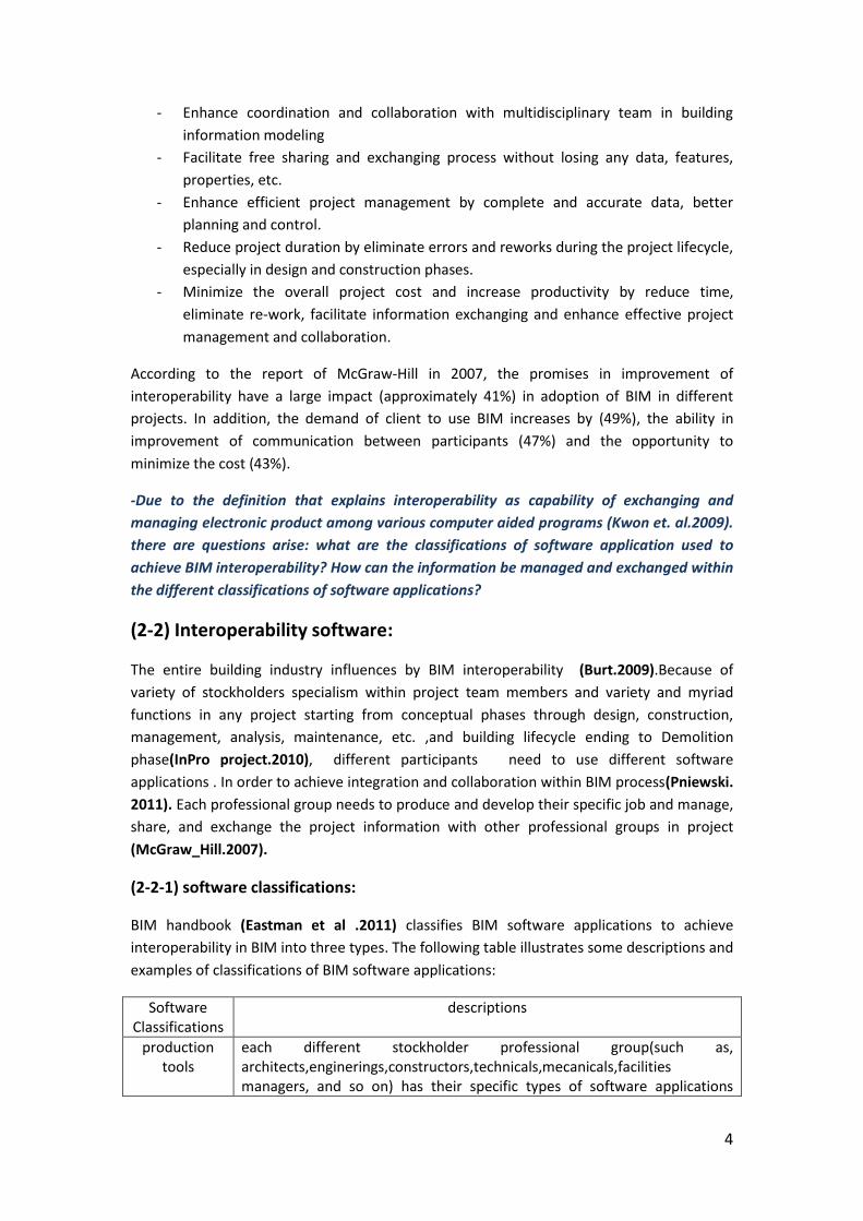
(2-2-1) software classifications:
BIM handbook (Eastman et al .2011) classifies BIM software applications to achieve
interoperability in BIM into three types. The following table illustrates some descriptions and
examples of classifications of BIM software applications:
Software Classifications
descriptions
production tools
each different stockholder professional group(such as, architects,enginerings,constructors,technicals,mecanicals,facilities managers, and so on) has their specific types of software applications
5
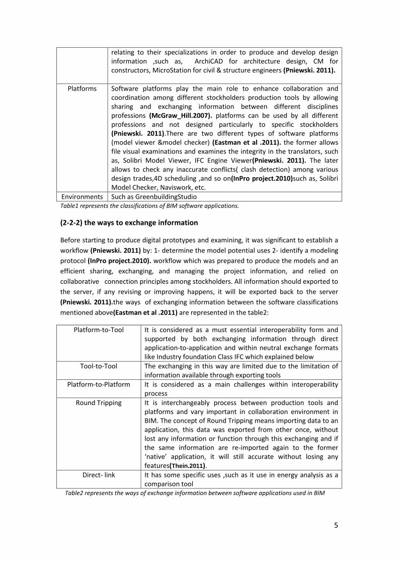
relating to their specializations in order to produce and develop design information ,such as, ArchiCAD for architecture design, CM for constructors, MicroStation for civil & structure engineers (Pniewski. 2011).
Platforms Software platforms play the main role to enhance collaboration and coordination among different stockholders production tools by allowing sharing and exchanging information between different disciplines professions (McGraw_Hill.2007). platforms can be used by all different professions and not designed particularly to specific stockholders (Pniewski. 2011).There are two different types of software platforms (model viewer &model checker) (Eastman et al .2011). the former allows file visual examinations and examines the integrity in the translators, such as, Solibri Model Viewer, IFC Engine Viewer(Pniewski. 2011). The later allows to check any inaccurate conflicts( clash detection) among various design trades,4D scheduling ,and so on(InPro project.2010)such as, Solibri Model Checker, Naviswork, etc.
Environments Such as GreenbuildingStudio Table1 represents the classifications of BIM software applications.
(2-2-2) the ways to exchange information
Before starting to produce digital prototypes and examining, it was significant to establish a
workflow (Pniewski. 2011) by: 1- determine the model potential uses 2- identify a modeling
protocol (InPro project.2010). workflow which was prepared to produce the models and an
efficient sharing, exchanging, and managing the project information, and relied on
collaborative connection principles among stockholders. All information should exported to
the server, if any revising or improving happens, it will be exported back to the server
(Pniewski. 2011).the ways of exchanging information between the software classifications
mentioned above(Eastman et al .2011) are represented in the table2:
Platform-to-Tool It is considered as a must essential interoperability form and supported by both exchanging information through direct application-to-application and within neutral exchange formats like Industry foundation Class IFC which explained below
Tool-to-Tool The exchanging in this way are limited due to the limitation of information available through exporting tools
Platform-to-Platform It is considered as a main challenges within interoperability process
Round Tripping It is interchangeably process between production tools and platforms and vary important in collaboration environment in BIM. The concept of Round Tripping means importing data to an application, this data was exported from other once, without lost any information or function through this exchanging and if the same information are re-imported again to the former ‘native’ application, it will still accurate without losing any features(Thein.2011).
Direct- link It has some specific uses ,such as it use in energy analysis as a comparison tool
Table2 represents the ways of exchange information between software applications used in BIM
6
Interoperability enhances various capabilities and determines different errors within these
ways of sharing and exchanging information across different software classifications
(Eastman et al .2011). However, before start to focus on these capabilities and limitations
within case study, the question arises here: How can this information be exchanged
between a variety of software classifications? Which facilities can support the information
exchange between different applications classifications mentioned above?
(2-3) Interoperability standards:
For realistic interoperability, software programs require having facilities which can support
exchanging data accurately. That is means; interoperability process requires standards or
protocols which lead to set a mutual language between different software applications
(Arana et al. 2006). Technology suppliers attempt to find universal accepted methods
(McGraw_Hill.2007) in order to transfer data throughout different software applications to
reach the market demands and to ensure that all object characteristics and attributes will
transfer accurately (Pniewski. 2011). It could be considered that tripping of data without
lost information is the key to achieve the benefits of BIM completely
(Golabchi&R.Kamat.2013).There are several exchanging file formats in Interoperability,
developed by a various technology vendors and industry groups, such as IGES (Initial
Graphic Exchange Specification) , DXF (Drawing eXchange Format) which is considered as a
2D exchange standard and limited to geometry elements, ISO (International Organization for
Standardization)which is considered as international slandered ,and STEP (Standard for The
Exchange of Product), CIMsteel integrated standard, and XML (eXtensible Markup Language)
(Eastman et al .2011)
The Major standard of 3D Data exchanging is IFC (Industry Foundation Classes) which has
significant utilizes in BIM. The interoperability standard adopted by software application
providing common languages to enhance sharing and exchanging data among various
applications that are used by project stockholders to enhance collaboration.(Pniewski. 2011)
Because of the fact that IFC is considered as AEC wide slandered specification (Pniewski.
2011) which has a popularity use in BIM models because it developed specifically to enable
standardized information exchange (Golabchi&R.Kamat.2013) and several technologies
providers in AEC software applications support this format (McGraw_Hill.2007), this
research chooses to investigate BIM interoperability through IFC (Industry Foundation
Classes) especially, on its modus operandi.
(2-4)Industry Foundation Classes (IFC):
(2-4-1)What is IFC?
Industry foundation classes is a data exchange standard based interoperability which is
considered as a schema ‘common data’ intended to illustrate definitions of extensible set of
coherent data representations of BIM (Eastman et al .2011) and provide a neutral
framework to integrate different of software applications that is used in AEC industry
throughout the whole building lifecycle. This schema consists of classes or entities,
attributed, and relationships among these entities .(Pniewski. 2011). IFC also defined as
7
Repository for the semantic data of building objects which includes geometry, connected
properties, and relationships (Thein.2011).
In AEC industry, the interoperability standards has been created and developed by
International Alliance for Interoperability (IAI) since 1995. In 1997, The first version of IFCs
(1.0) was generated and with a successful implementation of IFCs 2x edition2 which is
released in 2003 (Thein.2011).although it was designed based on the EXPRESS language
definitions of ISO-STEP which concentrated its efforts on detailed software applications
exchanges for particular engineering fields that might lead progressively to result
incompatible protocols, its developers tended to provide it a general definitions of
information and objects and task-specific models which support particular exchange can be
defined. In 2010, a new IFCs version was published and included 358 property set ,800 data
objects ( entities),and 121 data types, although those numbers reflected a complexity of
IFCs, it also reflected a complexity of building information which is need a different
applications across interdisciplinary stockholders (Eastman et al .2011).
(2-4-2) how does IFC work?
The modus operandi of IFC relies on enhancing extensibility and flexibility by providing a
facility which is instrumented with property sets (Psets) ,and (Proxies)(Pniewski. 2011;
Khemlani.2004). Optional Psets is belong to entities, those entities were defined in the IFC
model and are included the properties, such as FireRating of wall, the cost of flooring
materials, U-vale of facade, etc. Proxies, however, are new form of entities which were not
defined in a given IFC model and are included the geometry and Psets (Pniewski. 2011).
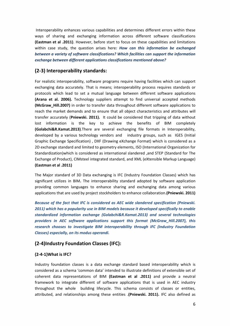
In general, IFC model includes a mutual spatial structure of building to coordinate, organize,
and access the building elements. This spatial structure arranges all object data into a
hierarchical way, such as: Project>site>building>building story>space .each higher level
contains a collection of the lower levels and all extension existed in lower level classes. Due
to the hierarchical structure of object sub-typing, objects that are used in exchanging
processes are entered through the tree includes subentries definitions. Each different level
of this tree shoes different relations and attributes with the wall entity. The example was
taken to explain this tree is a wall entity which is down the tree as displaying below in
figure1 (Eastman et al .2011).
Figure1 illustrates the IFC structure of defining wall
8
The IfcRoot level includes the information for managements the objects (who created the
objects and when it was created).IfcObjectDefinitions include the identification of the
opening wall components , such as doors, windows and others and also put the wall in a
whole building story assembly. IfcProductDefinitions identify the wall shape and location.
IfcElement consist of the relationships between different elements , such as the boundring
relationships of wall , the spaces which are isolated by wall and also carries all slots through
the wall and optionally which is optionally filling by doors or windows.the structural
elements will help the wall representing if the wall is structural (Eastman et al .2011).
The PsetWallCommon includes domain to be able to define: FireRating, Identifier,
Combustibility, AcousticRating, Compartmentation (firewall), IsExterior,
SarfaceSpreadOfFlame, ExtendToStructure, ThermalTransmittance . There is other more
Psets details will be supported if there is a need of them. Protruding components, slots,
notches are also supported (Eastman et al .2011).
Due to equipping a vast set of object definitions in IFC object model and because various
software applications that used by different stockholders implement only parts of these
object definitions , these applications need to be instrumented with identical subsets or
parts of IFC product data model in order to support the exchanging of data between those
applications. These subsets which is called IFC Model Viewer Definitions (MVDs) are a part
IFC schema including information specification for specific model exchange scenario and
have the ability to identify the expectative requirements for an exchange to be effective
(Eastman et al .2011& Pniewski. 2011;Gokce et al.2007&buildingSMART.2009).
(2-4-3) IFC limitation
Industry Foundation Class is not free from errors or limitations (Pniewski. 2011). The
following are some limitationsaccording to some categories relating to its modus operandi:
- Geometry parameters:
The design of IFC geometry supports the exchange processes of simple parametric model
among different systems, these systems like extruded forms or walls. Not all information
(particularly constraints and rules) that are needed, however, can be exchanged that leads
to require some editing in order to transfer editable parametric model (Eastman et al
.2011).
- Data Round tripping:
IFC has a problems with (round tripping information) because the round tripping of data is
not of the objective of IFC or it certification criteria due to several reasons: First, according
to exchange format, IFC just concentrates on the application functions results but it does not
focus on their obtaining or producing with taken into account that software vendors do not
accept the exporting of semantic information because it will expose the proprietary data and
trade mysteries . Second, the specification of IFC does not treat the exportation of certain
proprietary data types which uphold application functions, that mean, the re-importing of
IFC file( round tripping) cannot generate the origin file with full of its features. Therefore, the
objects features will continue to loss in every importing and exporting process (Thein.2011).
9
- Objects Relations:
In IFC releases, the relations are determined and engaged objects. Due to the fact that the
IFC promises to provide a rich sets of relations in some BIM applications to be able to use IFC
format in exchanging information and because of the myriad subclasses of IfcRelations that
are covering almost all required relations and due to the complexity in this area regarding to
relations and definitions, the structures of objects relations are repeated with each release.
Therefore, in each new release people do not know their utilities.
- Objects Properties:
As mentioned above, IFC concentrates on property sets (Psets) (Pniewski. 2011). The
complexity in properties arises due to their enormous numbers which are used to describe
all information relating to the objects. Some of the object definitions need to link with a lot
of sets of properties especially, in describing a particular performance, materials, and
contextual properties like weather information, wind, etc. . For instance, many Psets are
collected to describe many kinds of objects in building, such as wall, windows, and others.
There are also a lot of properties are joint with various material behaviors like mechanical
properties, fuel, thermal material, etc. As a result, missing in several properties might occur,
and there is no clear method to illustrate uncertainty (Eastman et al .2011).
In order to understand the capabilities and limitations of IFC interoperability through
different ways of sharing and exchanging information between different software
application classifications indicated above, the research chooses to inspect a case study
which examines some of these capabilities and limitations.
(2-5) Case Study:
(2-5-1) Descriptions:
A good example, which chosen in this research, was demonstrated in research work
published in 2011 by Pniewski . The purpose of selection this case study is because the
researcher concentrated on the examinations of IFC interoperability through a various
software applications classifications (production tools, platforms)employed in BIM on
different ways of transferring information (platform-tool , round tripping). These
examinations gave the opportunities to evaluate the impact of IFC interoperability on BIM
collaboration between different stockholders which is the main focus on this research. The
examination focused on parametric models especially. Attention was paid to no-standard
Psets because they might not inoperable through all software applications used in BIM. the
original model was built in ArchiCAD ‘authoring application’ as Architects-Concept Design’s
schema ,including three IFC entities :IfcWall, IfcColumn, and IfcSlab ( as their definitions in
ArchiCAD), then, exporting the model to Solibri model checker as IFC2x3 format which was
used as a model server to illustrate it as Start-Up Model loading to 3D parametric
modeling. The concept of these tests is to uptake the behaviors of design’ feature of the
objects by reorganizing the including and missing information through sharing and
exchanging process in order to determine expectations of re-using the information .
10
The researcher set eight of integrity evaluation criteria in this test which is: 1- element
geometry ‘tested the accuracy in geometry parametric model, 2- element relations ‘test the
relations among objects, 3-element color coding ‘tested inconsistencies in color coding of
elements which carry similar properties and attributions, 4- entity and element count ‘tested
qualities and completeness of element and entity’, 5- schedule of value ‘tested the accuracy
in property and attributed values, 6-entity attributes and 8-entity P-sets ‘tested the accuracy
in entity attributed and P-sets lists when exchanged, 8-check the completeness in model
tree structure.
This research will illustrate some of these applications to determine overall understanding
of the current IFC interoperability capabilities and limitations.
(2-5-2) Illustrations:
The case -study examinations will be represented and divided according to the different
ways of transferring IFC files through some of different software application classifications
which are indicated in literature review (3):
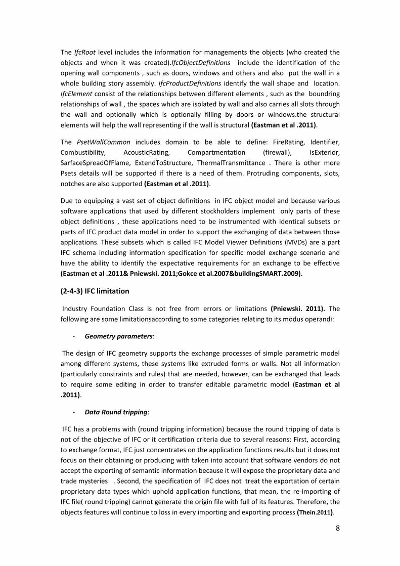
- Tool-to-Platform( model server)-to-Tool:
The IFC Mark-Up Model was transferred to different Production Tool software applications,
such as: Revit, MicroStation. Figure2 (A-B) represents the testing results according to setting
criteria:
Figure2 illustrates testing results of (A-B ) applications regarding (Tool-to-Platform-to-Tool)
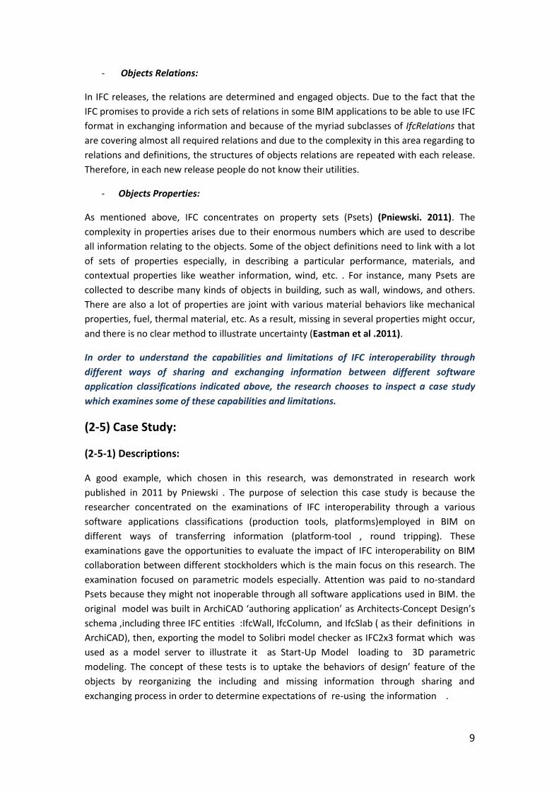
- Tool-to-Platform( model server)-to-Platform:
The IFC Mark-Up Model, which exported from ArchiCAD to model server, was transferred to
different Platform software applications, such as: A- Solibri Model Viewer , B- DDS-CAD
Viewer, C- Nemetschek IFC Viewer; D- IFC Engine Viewer Figure3 represents the testing
results according to setting criteria:
11
Figure3 illustrates testing results of (A-B-C-D) applications regarding (Tool-to-Platform-to-Platform)
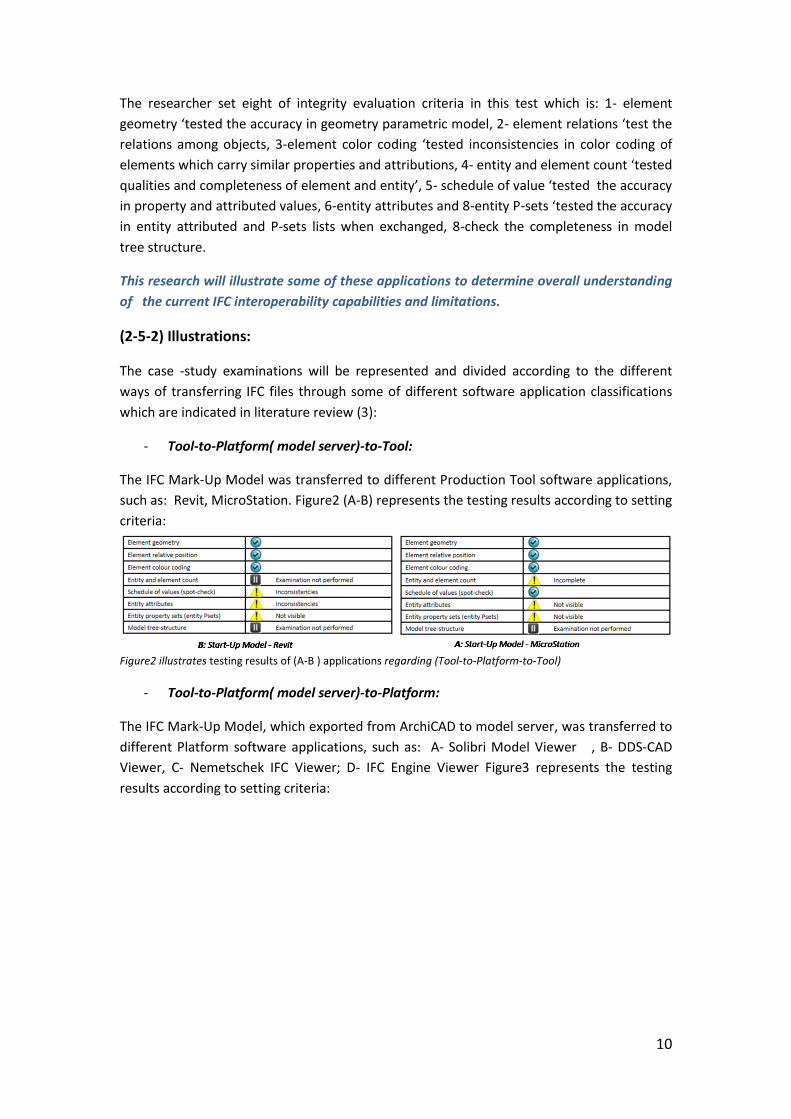
- Data Round Tripping:
The IFC Mark-Up Model, which exported from ArchiCAD to model server, was transferred
from model server to Digital Project (A) , then, did some development in ArchiCAD and
exported the file back to server .Then, imported it again to the Digital Project (B). Figure4
represents the testing results according to setting criteria:
Figure4 illustrates testing results of (A-B-C-D) applications regarding (Tool-to-Platform-to-Platform)
(2-5-3) Discussion:
According to examinations results illustrated Figure 2(A-B), exchanging model through Tool-
to- Platform( model server)-to-Tool ways has many limitations, especially, in exchanging
(entity attributed and entity Psets), other limitations appeared in schedule of values in Revit
and entity and element count in MicroStation although transferring element geometry,
element relations ,and element color was accurate in both.
According to examinations results illustrated Figure 3(A-B-C-D), the level of accuracy the in
exchanging model through Tool-to-Platform(model server)-to-Platform is better than the
previous ways. The same Six transformed criteria is completely and accuracy in the all
software examined, problems were addressed just in: Element color coding in DDS-CAD
Viewer, Entity attributes in Solibri Model Viewer, and the both previous problems addressed
in IFC Engine Viewer, while there is no problem addressed in Nemetschek.
12
According to examinations results illustrated Figure 4(A-B), the big problem here when the
model Data Round Tripping, it lost more information .because at the first exchange there
are two criteria missing (entity P-sets and entity attributes), while in the second exchange
two more elements had problems(element geometry and element relations).
(2-5-4) lesson learned:
- The level of accuracy in exchanging information when the model sever play as
platforms between tools and platforms software application is better than when it is
play the same role among tools and tool application.
- When exchanging data between tool and tool application (model sever play as
platforms), information exchanged always have problems two criteria (entity
attributed and entity Psets) which are very important as indicated in literature
review.
- If information is round tripping, the expectations of lost more of information should
be taken into account.
3- Conclusion:
This research concentrated on investigations and understanding BIM interoperability
(capabilities and limitations) by a combination of two factors (interoperability software and
Interoperability standard) focusing on Industry foundation classes IFC the most popular
standard used in BIM in order to recognize the concept of interoperability within AEC
industry and its influences in adoption of Building Information modeling. Attention was paid
to describe the ways of IFC file be generated and the IFC ‘schema components , attributes
entity , properties and relationships among its components’, and the impact of each element
in interchangeably process to achieve an accurate sharing and exchanging information
between different stockholder professions was taken into account . The (various
classifications of software applications employed in BIM, different ways of exchanging
information between these applications, and case study to examine the interoperability
capabilities and limitations across different criteria relating to cotenants mentioned
previously) are also illustrated.
Although there are some current limitations in IFC formats, it causes an enormous
improvement in AEC industry particularly in adoption of Building information modeling. The
complexity of Building information model, various stockholders specialism, increasing the
number of software applications and The current inability of interoperability standards to
enhance free and bidirectional sharing and exchanging information and round tripping data
among different software application classifications the main cases to increase uncertainty
in exchanging information between project participants.
Project participants must be aware about the limitations in exchanging data in order to
increase their ability to deal with interoperability current situation and minimize rework,
the interoperability issues cannot completely and easily resolved without fix workflow,
principles, and rules to determine which information needs to be exchanged. Software
developers should develop interoperability slandered and software which will able to
13
develop exchanging information and round tripping data without any inconsistencies,
uncompleted or missing any information. In future research, how can the data round
tripping without any missing and inconsistencies?
4- References:
- Eastman, C., Teicholz, P., Sacks, R., & Liston, k. (2011). BIM hand book (2nd ed). New
Jersey : John Wiley & Sons, Inc.
- The InPro consortium. (2010). Collaboration process, framework for collaboration.
The European commission.
- Gallaher, M., O’Connor, A. , Dettbarn, Jr.& Gilday, L.(2004) . Cost Analysis of Inadequate Interoperability in the U.S. Capital Facilities Industry. National Institute of
Standards and Technology. Advanced Technology Program Information Technology and Electronics Office Gaithersburg, Maryland.
- Thein,V.(2007). Industry Foundation Classes (IFC) BIM Interoperability Through a Vendor-Independent File Format. Bentley sustaining infrastructure. USA.
- McGraw_Hill(2007). Interoperability in the Construction Industry. - Pniewski, V. , (2011) . Building Information Modellind (BIM) Introperability Issues in
Light of Interdisciplinary Collaboration. London.UK. - Aranda-Mena,G.& Wakefield, R. (2006).INTROPERABILITY OF BUILDING
INFORMATION:MYTH OR REALTIY .RMIT University, Australia. - Kwon,o.,Lee,G., Kim, S., Sin,Y., Hwang, J.&Chae,K. (2009).INTROPERABILITY ISSUES IN
CROSS-DISCIPLINARY COLLABORATIONS OF IRREGULARLY SHAPED BUILDING:THE CASE OF DONGDAEMUN DESIGN PLAZA AND PARK.Yonsei University. Seoul,Korea
- Kamat, v.& Golabchi, A.(2013). EVALUATION OF INDUSTRY FOUNDATION CLASSES FOR PRACTICAL BUILDING INFORMATIO MODELING INTEROPERABILITY. University of Michigan, USA.
- Burt, B. (2009). BIM Interoperability. STRUCTURE magazine, Technology information and updates on the impact of technology on structural engineering. pp. 19-21.