User Manual - Dahua Wiki
175
Overview 1 User Manual
-
Upload
khangminh22 -
Category
Documents
-
view
0 -
download
0
Transcript of User Manual - Dahua Wiki

Overview 1
User Manual

Dahua Technology Co., Ltd Quick Application Guide
I
Table of Contents
1 Overview ............................................................................................................................................................ VI
2 Before Installation ............................................................................................................................................. 1
2.1 Set Server IP Address .............................................................................................................................. 1
2.2 Set Server System Time .......................................................................................................................... 2
3 Install &Run DSS Express ............................................................................................................................... 5
3.1 Server Config Requirement ..................................................................................................................... 5
3.2 Installa&Run .............................................................................................................................................. 5
3.3 Change Initial Password .......................................................................................................................... 8
3.4 DSS Server Login ................................................................................................................................... 14
4 Add Encoder ..................................................................................................................................................... 16
4.1 Manually Add ........................................................................................................................................... 16
4.2 Auto Add ................................................................................................................................................... 19
4.2.1 Auto Search Encoder ...................................................................................................................... 19
4.2.2 Other Platform Input ....................................................................................................................... 22
5 User ..................................................................................................................................................................... 24
5.1 Add User .................................................................................................................................................... 24
5.2 Modify User ............................................................................................................................................... 26
5.3 Delete User ................................................................................................................................................ 27
6 Preview ............................................................................................................................................................... 29
6.1 Organization Preview ............................................................................................................................. 29
6.2 Device Preview ........................................................................................................................................ 31
6.3 Channel Preview ..................................................................................................................................... 32
6.4 Show Preview .......................................................................................................................................... 33
7 Record Config ................................................................................................................................................... 38
7.1 Local Storage Disk Setup ...................................................................................................................... 38
7.2 Network Disk Setup ................................................................................................................................ 40
7.3 Create Storage Plan ............................................................................................................................... 42
8 Playback ............................................................................................................................................................. 45
8.1 Record Search&Playback ...................................................................................................................... 45
8.2 Download Record ................................................................................................................................... 47
9 Download Center ............................................................................................................................................. 50
9.1 Download Record ................................................................................................................................... 50
9.1.1 Timeline Cut ................................................................................................................................. 51
9.1.2 Select Record List ....................................................................................................................... 53
9.1.3 Tag Record ................................................................................................................................... 54
9.2 Download Management ......................................................................................................................... 55
9.2.1 Download Complete ................................................................................................................... 55
9.2.2 Pause/Start Download ................................................................................................................ 55
9.2.3 Delete Download Task ................................................................................................................ 56
10 Map Application ............................................................................................................................................. 58
10.1 Add Map ................................................................................................................................................. 58
10.2 Add Sub Map ......................................................................................................................................... 62
10.3 Add More Maps ..................................................................................................................................... 64
10.4 Map Application ..................................................................................................................................... 66

Dahua Technology Co., Ltd Quick Application Guide
II
10.4.1 Main Map Setup ........................................................................................................................ 66
10.4.2 Pane Application ....................................................................................................................... 67
10.4.3 Filter Device Type ..................................................................................................................... 68
10.4.4 Tool .............................................................................................................................................. 69
11 Event ................................................................................................................................................................. 71
11.1 Alarm Scheme Config ........................................................................................................................... 71
11.2 Alarm Manager ...................................................................................................................................... 76
11.2.1 Alarm Prompt ............................................................................................................................. 76
11.2.2 Real-time Alarm Processing .................................................................................................... 77
11.2.3 History Alarm Search&Process ............................................................................................... 81
12 Video Wall ........................................................................................................................................................ 85
12.1 Add Decode Device .............................................................................................................................. 85
12.2 Add Video Wall ...................................................................................................................................... 87
12.3 Video Wall Control ................................................................................................................................ 92
12.3.1 Instant Output to Wall ............................................................................................................... 92
12.3.2 Output to Video Wall ................................................................................................................. 93
12.3.3 Wall Schedule ............................................................................................................................ 95
12.3.4 Control Function ........................................................................................................................ 99
13 Person............................................................................................................................................................. 104
13.1 Add Person .......................................................................................................................................... 104
13.1.1 Add Department ...................................................................................................................... 104
13.1.2 Add A User ............................................................................................................................... 106
13.1.3 Batch Add ..................................................................................................................................114
13.2 Delete User ...........................................................................................................................................118
13.3 Batch Issue Card..................................................................................................................................119
14 Access Control ............................................................................................................................................. 122
14.1 Add Access Control Device ............................................................................................................... 122
14.2 Time Template&Holiday Group ......................................................................................................... 124
14.2.1 Time Template ......................................................................................................................... 124
14.3 Access Control Console ..................................................................................................................... 126
14.3.1 Door Config .............................................................................................................................. 127
14.3.2 Access Control Channel Control ........................................................................................... 129
14.3.3 Event Details ............................................................................................................................ 132
14.3.4 Global Control .......................................................................................................................... 133
14.3.5 Scheme Management ............................................................................................................ 136
14.4 Door Group .......................................................................................................................................... 140
14.5 Advanced Function ............................................................................................................................. 143
14.5.1 First Card Unlock .................................................................................................................... 143
14.5.2 Multiple Card Unlock .............................................................................................................. 145
14.5.3 Anti-passback .......................................................................................................................... 150
14.5.4 Inter-lock ................................................................................................................................... 154
14.5.5 Remote Verification ................................................................................................................ 156
15 ANPR ............................................................................................................................................................... 159
15.1 Add ANPR Device ............................................................................................................................... 159
15.2 Picture Storage Keyboard Setup ...................................................................................................... 160
15.3 Road Surveillance Application .......................................................................................................... 161
15.3.1 Passed vehicle ........................................................................................................................ 161

Dahua Technology Co., Ltd Quick Application Guide
III
15.3.2 Passed Vehicle Record Search ............................................................................................ 164
15.3.3 View Passed Vehicle Record ................................................................................................ 167
15.3.4 Export Passed Vehicle Record ............................................................................................. 167

Dahua Technology Co., Ltd Quick Application Guide
IV
Welcome
Thank you for using our Digital Surveillance System (DSS) Express!
This user’s manual is designed to be a reference tool for operation of your system.
Here you can find detailed operation information about DSS.

Dahua Technology Co., Ltd Quick Application Guide
V
Important Safeguards and Warnings
Please read the following safeguards and warnings carefully before using the product in order to avoid
damages and losses.
Note:
Do not expose the device to lampblack, steam or dust. Otherwise it may cause fire or electric
shock.
Do not install the device at position exposed to sunlight or in high temperature. Temperature
rise in device may cause fire.
Do not expose the device to humid environment. Otherwise it may cause fire.
The device must be installed on solid and flat surface in order to guarantee safety under load
and earthquake. Otherwise, it may cause device to fall off or turnover.
Do not place the device on carpet or quilt.
Do not block air vent of the device or ventilation around the device. Otherwise, temperature in
device will rise and may cause fire.
Do not place any object on the device.
Do not disassemble the device without professional instruction.
Warning:
Please use battery properly to avoid fire, explosion and other dangers.
Please replace used battery with battery of the same type.
Do not use power line other than the one specified. Please use it properly. Otherwise, it may
cause fire or electric shock.
Special Announcement
This manual is for reference only.
All the designs and software here are subject to change without prior written notice.
All trademarks and registered trademarks are the properties of their respective owners.
If there is any uncertainty or controversy, please refer to the final explanation of us.

Dahua Technology Co., Ltd Quick Application Guide
VI
1 Overview
Product Positioning
DSS Express is an important surveillance platform product in DSS family (Dahua Security Software),
design for medium-small project. DSS Express integrates video, access control, intercom, alarm
controller, entrance & exit, facial recognition and etc., combining with front-end device function. DSS
Express supports simple, reliable, open and more features which bring user with HD, smart, safe
experience. Meantime, DSS Express adopts standard C/S structure, and there are free and premium
versions available.
Highlights
Standard C/S structure, client integrates config and management function
Global logic config page, different users will see different config content
Hardware decoding, output more HD videos
Find device, quickly add device, quickly manage device
Password error-lock user, find back password via security questions, anti-attack
https certificate input
Auto and manual back up data
Provide platform secondary development SDK docking

Dahua Technology Co., Ltd
1
2 Before Installation
2.1 Set Server IP Address Step 1. Connect server and switch via Ethernet cable.
Step 2. Click “Start”,and select Network,see Figure 2-1.
Figure 2-1
Step 3. In-pop up page, select “Change adapter settings”,see Figure 2-2.

Dahua Technology Co., Ltd
2
Figure 2-2
Step 4. In Figure 2-3, select corresponding network card to set IP V4 address.
Figure 2-3
2.2 Set Server System Time Step 1. Click system time at the lower right corner in windows, see Figure 2-4.

Dahua Technology Co., Ltd
3
Figure 2-4
Step 2. Set time zone and DST,see in Figure 2-5 .

Dahua Technology Co., Ltd
4
Figure 2-5

Dahua Technology Co., Ltd
5
3 Install &Run DSS Express
3.1 Server Config Requirement Server config requirement is in Chart 3-1.
DSS Server Hardware Requirement
Recommend
CPU: Intel® Xeon® CPU E3-1220 v5 @3.00GHz
Memory: 8GB
Ethernet card: 1Gps
DSS path capacity: 500G and higher
Low-end
CPU: I3-2120
Memory: 8GB
Ethernet card: 1Gps
DSS path capacity: 200G and higher
Chart 3-1
3.2 Installation & Run Step 1. Double click to install and enter installation mode, see Figure 3-1.
Figure 3-1

Dahua Technology Co., Ltd
6
Step 2. Please check I have read and agree the DSS agreement, see Figure 3-2. Click “Next”
button to enter next step.
Figure 3-2
Step 3. Based on network setup, determine if you will change Https port, default port is 443,
see Figure 3-3,If you do not change it or have completed change, click “Next” button to
enter next step.
Figure 3-3
Step 4. Server default installation path is C:\DSS Express\Server, the system will auto detects
free space in this path, see Figure 3-4. If want to change path, click “Browse” button to
select other installation path, and then click “Install” button to install.

Dahua Technology Co., Ltd
7
Figure 3-4
Note:
If “Install “button is grey, please check if installation directory is correct, or if free space in
this directory is enough for the system.
Step 5. Progress is in Figure 3-5. The whole process needs about 5-10 minutes, please wait.
Figure 3-5
Step 6. Installation is complete, click “Run “button to open server, see Figure 3-6.
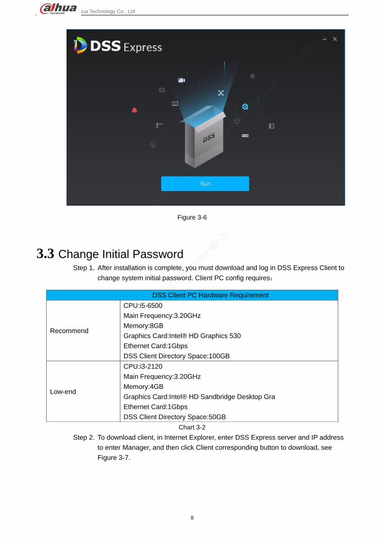
Dahua Technology Co., Ltd
8
Figure 3-6
3.3 Change Initial Password Step 1. After installation is complete, you must download and log in DSS Express Client to
change system initial password. Client PC config requires:
Chart 3-2
Step 2. To download client, in Internet Explorer, enter DSS Express server and IP address
to enter Manager, and then click Client corresponding button to download, see
Figure 3-7.
DSS Client PC Hardware Requirement
Recommend
CPU:i5-6500
Main Frequency:3.20GHz
Memory:8GB
Graphics Card:Intel® HD Graphics 530
Ethernet Card:1Gbps
DSS Client Directory Space:100GB
Low-end
CPU:i3-2120
Main Frequency:3.20GHz
Memory:4GB
Graphics Card:Intel® HD Sandbridge Desktop Gra
Ethernet Card:1Gbps
DSS Client Directory Space:50GB

Dahua Technology Co., Ltd
9
Figure 3-7
Step 3. double click the client installation file to install, see Figure 3-8.
Figure 3-8
Step 4. Check I have read and agree the agreement,see Figure 3-9. Then click “Next”
button to go to next.

Dahua Technology Co., Ltd
10
Figure 3-9
Step 5. System default installation path is in Figure 3-10. If you want to change installation
directory, click “Browse” button to change. After you select a path, click “Install
“button to start installation.
Figure 3-10
Note:
If “Install “button is grey, please check if installation directory is correct, or if free space in
the directory is enough for system.
Step 6. Progress is in Figure 3-11, and this process needs about 1-3 minutes, please wait.

Dahua Technology Co., Ltd
11
Figure 3-11
Step 7. Installation is complete in Figure 3-12, click “Start now “button to run the client.
Figure 3-12
Step 8. Client login page is in Figure 3-13. Please click to expand server config
page.
Dahua Technology Co., Ltd
12
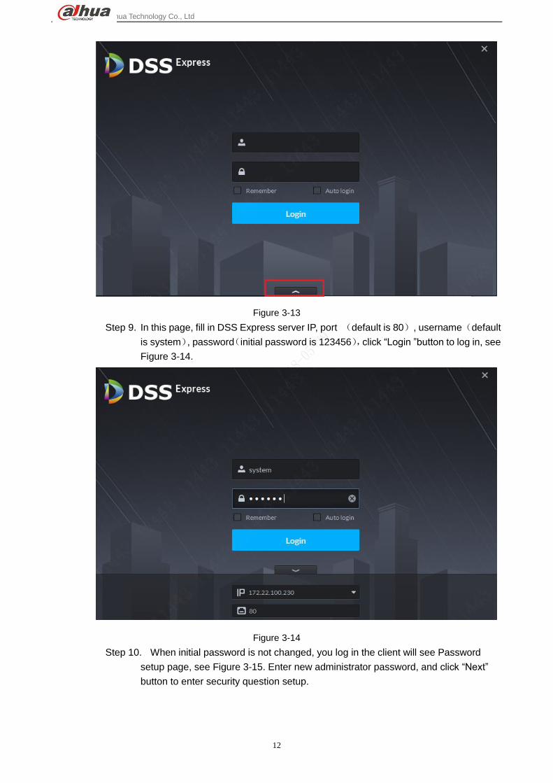
Figure 3-13
Step 9. In this page, fill in DSS Express server IP, port (default is 80), username(default
is system), password(initial password is 123456),click “Login ”button to log in, see
Figure 3-14.
Figure 3-14
Step 10. When initial password is not changed, you log in the client will see Password
setup page, see Figure 3-15. Enter new administrator password, and click “Next”
button to enter security question setup.

Dahua Technology Co., Ltd
13
Figure 3-15
Step 11. In Figure 3-16, complete security questions accordingly, clicklock” button to
complete initial password change.
Figure 3-16
Step 12. Click “OK”button and system completes change and auto log in client homepage,
see Figure 3-17.

Dahua Technology Co., Ltd
14
Figure 3-17
3.4 DSS Server Login Step 1. On desktop of DSS Express server, double click DSS Server icon to log in DSS
Express config system. Follow the instructions to enter username and password,
and click “Login “button to log in DSS Server system, see Figure 3-18.
Figure 3-18
Step 2. View if server is online or not, its normal status is in Figure 3-19.

Dahua Technology Co., Ltd
15
Figure 3-19

Dahua Technology Co., Ltd
16
4 Add Encoder
4.1 Manually Add Log in DSS Express Client,and enter device module in management bar to add, edit and delete
device. Steps:
Step 1. In Express Client homepage, click “Device “module to enter Device, see Figure 4-1.
Figure 4-1
Step 2. Device management page is in Figure 4-2, click“Add”button to manually add.

Dahua Technology Co., Ltd
17
Figure 4-2
Step 3. Add device page is in Figure 4-3, first select add device method to be IP address,
and device category is “Encode”,
Figure 4-3
Step 4. According to page requirement, fill in device info, include: device name, IP address,
port no.(default is 37777), username. If you have not created organization node,
then the device is under node Video by default. See Figure 4-4. Confirm the info all
be right, click“Add” button to add. Device network communication is properly
working, then server will auto get device type and channel info.

Dahua Technology Co., Ltd
18
Figure 4-4
Step 5. After device is added, you can see device list as in Figure 4-5. You can edit, device
and set online device.
Figure 4-5
Step 6. If the system gotten device type is incorrect or needs to be changed, please click
Edit button of corresponding device, see Figure 4-6.
Figure 4-6

Dahua Technology Co., Ltd
19
Step 7. Device edit page is in Figure 4-7. A user can modify corresponding info accordingly.
Device category cannot be changed here, but you can change device type. See
Figure 4-7 and Figure 4-8.
Figure 4-7
Figure 4-8
4.2 Auto Add
4.2.1 Auto Search Encoder
Auto search function allows user to search all devices in DSS Express server network, or all users in
network segment set by user. A user can add device he/she wants. Steps:

Dahua Technology Co., Ltd
20
Step 1. In Device page, click “Auto Search “button to enter auto search page, see Figure
4-9.
Figure 4-9
Step 2. Default search page and results are in Figure 4-10.
Figure 4-10
Step 3. In search result, a user can select one, select multiple or select all (current page),
see Figure 4-11. Confirm and clicklock” button to add device into DSS Express
platform.

Dahua Technology Co., Ltd
21
Figure 4-11
Step 4. According to system prompt, select server, organization, and fill username and
password to batch log in device. See Figure 4-12. Confirm info and click “OK”
button.
Figure 4-12
Step 5. After you add device, see Figure 4-13.

Dahua Technology Co., Ltd
22
Figure 4-13
4.2.2 Other Platform Input
DSS Express supports device input from P2P platform and local PSS.
Figure 4-14

Dahua Technology Co., Ltd
23
Figure 4-15

Dahua Technology Co., Ltd
24
5 User
User manager module mainly add user, modify user, delete user and set user right. The system has 3
types of user by default as administrator (all rights), advanced user, general user. All added user must be
in these types, and different user types have different rights. Rights within each user type can be
adjusted within the range.
5.1 Add User Step 1. Via add button in navigation bar enter homepage, and then click User icon.
Figure 5-1
Step 2. On the left, select user type within the 3 types. An administrator has all rights, followed by
advanced user and general user respectively. If you want to add an advanced user, then
select Advanced User on the left. Click .

Dahua Technology Co., Ltd
25
Figure 5-2
Step 3. Fill in user info according to your need. You can select to verify MAC address (for PC
Client only), set user validity and etc. In device and right list, you also can select
corresponding device and right module accordingly. After setup, click Add button to add
user.
Figure 5-3
Step 4. After you add user, added user will be shown on the left. Click the username to view user
info and right. Green means online while red means offline.

Dahua Technology Co., Ltd
26
Figure 5-4
5.2 Modify User You can modify user basic info and right, but you cannot change user type. To change user type, you shall delete
the user and add again.
Step 1. Same with adding user, just enter user manager module. On the left, select username you
want to modify, and click button.
Figure 5-5

Dahua Technology Co., Ltd
27
Step 2. In shown user modification page, change basic info and right, click OK.
Figure 5-6
5.3 Delete User Step 1. Same with adding user, just enter user manager module. On the left, select username you
want to delete and click .
Figure 5-7
Step 2. In the shown figure, click OK to delete.
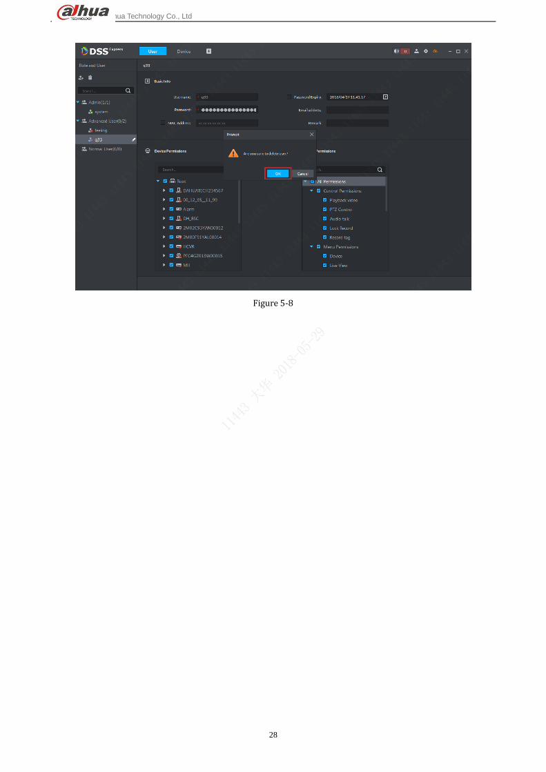
Dahua Technology Co., Ltd
28
Figure 5-8

Dahua Technology Co., Ltd
29
6 Preview
Log in DSS Express client, and in homepage, enter Live Preview module. It supports
organization preview, preview by device, free channel preview and preview by
view(must add view first).
6.1 Organization Preview Step 1. In device tree on the left, it supports display of total device of current organization
and online device. See Figure 6-1. Please select window number in tools at bottom
before preview.
Figure 6-1
Step 2. Drag organization node to the right window, and system will open the first N video
channels in this organization, N is number of windows. See Figure 6-2. If N is 4, it
will open 4 video channels in this organization.

Dahua Technology Co., Ltd
30
Figure 6-2
Step 3. Select one organization, right click it to set tour preview of all channels in this
organization. See Figure 6-3.
Figure 6-3
Step 4. During tour, you can click Stop button or right click in window to turn off tour,
see Figure 6-4.

Dahua Technology Co., Ltd
31
Figure 6-4
It supports right click to enable video tour of organization node, tour time can be:10s, 30s, 1min,
2min, 5min, 10min.
It supports display of device tree by name or IP.
It supports ascending/descending/random display of device tree.
It supports right click to hide offline node.
6.2 Device Preview Step 1. In “Local Config—General”, check “Show device node”,see Figure 6-5.

Dahua Technology Co., Ltd
32
Figure 6-5
Step 2. Other operations are same with organization preview, as you drag a device into
preview window to open its video, and right click to set tour.
6.3 Channel Preview Step 1. Cancel check of “Local Config—General”-“Show device tree mode”(save this setup
and client will auto reboot),preview device tree in channel mode, see Figure 6-6.

Dahua Technology Co., Ltd
33
Figure 6-6
Step 2. A user can auto select channel and preview in window. Right click channel, to add
into favorite, see Figure 6-7.
Figure 6-7
6.4 Show Preview Step 1. In“Live”interface, device list is on the left, select channel and double click it or drag it
into video window. If you double click device, then you can open all channels of the

Dahua Technology Co., Ltd
34
device. Window shows live preview of this device.
Figure 6-8
No. Parameter Note
1 Stream Info and
Shortcut
Show encode format, stream info and shortcut. Shortcuts:
:Enable or disable instant playback, playback time is set in
“Local Config”. Preconditon of instant playback is that there is
record at center or locally on device. Center record has
priority.
:Enable or disable audio.
:Enanle or disable intercom. In“Local Config>General”,
check “Self-adaptive intercom”. When you enable intercom,
no pop-up window will appear, and auto adaptive applies to all
parameters.
:Enable or disable local record.
:Snapshot.
2 Favorites and Device
Tree Search
Support , search by device name or
channel name.
:Add, delete or rename favorites. Support tour of favorites.
3 Map Preview map info in windows:GIS map and reaster map.

Dahua Technology Co., Ltd
35
No. Parameter Note
4 Map
Support to save current video window to video. View supports
three levels: node, group and view respectively. It supports node,
node tour viewo, tour time can be 10s, 30s, 1min, 2min, 5min,
10min. Max 100 views.
5 PTZ Speed dome PTZ adjust.
6 Save current video as view.
7 Aspect Ratio Select video window aspect ratio, it supports to play video in actual
acpect ratio or full screen.
8 Split Split video. You can slip video into 1 to 64 windows, or click
to customize.
9 Full Screen Set video to full screen. To exit, you can click Esc otr right click and
select exit full screen.
Chart 6-1
Step 2. Right click preview window, you can set current video, see Figure 6-9.
Figure 6-9

Dahua Technology Co., Ltd
36
Parameter Note
Close Video Close current window.
Close All Close all windows.
Enable Audio Same as ,turn on or off audio of camera.
Enable Talk Same as ,turn on or off corresponding talk function of device.
In“Local Config>General”check“Self-adaptive talk”,to enable
talk, no pop-up to auto adjust parameter.
Start Local
Record
Same as ,record A/V in current window, and save to local
PC.
Snapshot Same as ,save image in current window as picture file to
picture folder(Save one picture every time you call).
Continuous
Snapshot Same as ,save image in current window as picture file to
picture folder(Snapshot three pictures every time).
Alarm Output
Control Control alarm output ON/OFF.
Stream Type Switch among “main stream”, “sub stream 1”, “sub stream 2”.
Note:
If you select “sub stream 1”, “sub stream 2”, and when you add
encoder in Manager, in dropdown list of “Stream”, select “support
sub stream 1”, “support sub stream 2”.
Live/Fluency Enter“live priority”, “fluency priority”, “balance priority”or custom.
Video
Adjustment Adjust image and enhance video.
Window Mode Support standard mode, 1+3 and 1+5.
Fisheye
Installation Wall-mount, ceiling and grounding.
Fisheye View Fisheye view has different installation modes and angles:
Panoroma-360 degrees
Dual panoroma-Two 180 degrees
4-split-Split entire video into four splits,up/down/left/right, each
blockcan be adjusted direction seperately
Single video-one video

Dahua Technology Co., Ltd
37
Parameter Note
Add to Favorite Add this channel or all channels into favorites
Full Screen Switch video window to “full screen”mode. If you want to exit“full
screen”,you can double click window or right click and select exit.
Switch to
Playback Switch preview to playback without going back to homepage.
Chart 6-2

Dahua Technology Co., Ltd
38
7 Record Config
7.1 Local Storage Disk Setup DSS Express will auto detect all disk and storage space, and provide a more convenient
storage disk method, steps:
Step 1. In Client homepage, click “Config”to enter config module, see Figure 7-1.
v
Figure 7-1
Step 2. In config page, click “Storage”to enter storage config, see Figure 7-2.
Figure 7-2
Step 3. DSS Express server will auto detects Express server installation disk info(Not PC
Client disk info),see Figure 7-3.

Dahua Technology Co., Ltd
39
Figure 7-3
Step 4. Click split button to create DSS Express storage, see Figure 7-4.
Figure 7-4
Step 5. Select storage space type, video or picture, see Figure 7-5. If you need to save
ANPR device picture, you shall set storage space type to be picture.
Figure 7-5
Step 6. According to need and disk free space, set storage space size. Min value is 10GB,
see Figure 7-6. Confirm it and click button to complete setup.

Dahua Technology Co., Ltd
40
Figure 7-6
Step 7. After disk is complete, see Figure 7-7. In the red box, the value is 50GB just set.
Figure 7-7
Step 8. If you want to this storage space, you can click this segment in disk, and click Delete
button in prompt page, see Figure 7-8.
Figure 7-8
7.2 Network Disk Setup Step 1. First park of operation here is same with local storage disk setup, see Figure 7-9.

Dahua Technology Co., Ltd
41
Click Add button to add network disk.
Figure 7-9
Step 2. In system pop-up page, fill in network storage device IP address, confirm and click
“OK” button to add, see Figure 7-10.
Figure 7-10
Step 3. Format disk.
Step 4. Network disk list is in Figure 7-11. Green means there is free space and red means
storage is already full and is overwriting.

Dahua Technology Co., Ltd
42
Figure 7-11
7.3 Create Storage Plan Step 1. In Client homepage, click “Config” in management bar to enter Config module, see
Figure 7-12.
Figure 7-12
Step 2. Please select one video channel on the left, and then click record
config button on the right, see Figure 7-13.

Dahua Technology Co., Ltd
43
Figure 7-13
Step 3. In system pop-up page, please select record storage path (server/device), stream
type(main stream, sub stream 1, sub stream 2), time template, confirm info and
click “OK” button to create record plan for this channel, see Figure 7-14.
Figure 7-14
Step 4. After record plan is added, see Figure 7-15. A user can open and close plan, modify
and delete plan.

Dahua Technology Co., Ltd
44
Figure 7-15

Dahua Technology Co., Ltd
45
8 Playback
8.1 Record Search&Playback Step 1. In DSS Express Client homepage, click “Playback” to enter record playback module,
see Figure 8-1.
Figure 8-1
Step 2. Record playback page is in Figure 8-2. Firstly select channel and storage location
for playback. If you set this channel in record plan, it is stored on server.

Dahua Technology Co., Ltd
46
Figure 8-2
Step 3. Select time to search, click to open calendar, if there is record, you can see a blue
dot on date, see Figure 8-3. Please select date with record to search.
Figure 8-3
Step 4. Record search result is in Figure 8-4. Double click time with record on time axis to
playback record by time (you can scroll to zoom in time axis). Click play button in
window to start play from the earliest time.

Dahua Technology Co., Ltd
47
Figure 8-4
Step 5. During playback, you can control record via tools at bottom, see Figure 8-5.
Figure 8-5
8.2 Download Record Step 1. Follow previous section, in playback page, click cut button, and select start time
and end time on time axis to download record. See Figure 8-6. Record download
supports many formats: dav, avi, mp4, flv and asf.

Dahua Technology Co., Ltd
48
Figure 8-6
Step 2. Click download and go to download center, see Figure 8-7. A user can pause and
delete downloading task via control button.
Figure 8-7
Step 3. You can click download button to enter download center, you can download
record by record list and tag. See Figure 8-8.

Dahua Technology Co., Ltd
49
Figure 8-8

Dahua Technology Co., Ltd
50
9 Download Center
Download center provides 3 types of download modes, including timeline, record list and tag. You can
pause, delete downloaded record.
9.1 Download Record Before downloading, please select channel, time, storage position accordingly to search record,
see Figure 9-1. Result in Figure 9-2.
Figure 9-1

Dahua Technology Co., Ltd
51
Figure 9-2
9.1.1 Timeline Cut
Step 1. In search result, click Timeline tab, and select display of timeline, see Figure 9-3.
Figure 9-3
Step 2. Move mouse to timeline, you can see a small pair of scissors. You can click timeline
to select start time and end time, then in system pop-up prompt box, confirm the
selected time range and select record storage format. See Figure 9-4. There are 5
formats: dav, avi,mp4,flv and asf. Please select accordingly.

Dahua Technology Co., Ltd
52
Figure 9-4
Step 3. Confirm download info and click OK to start downloading. See Figure 9-5.
Figure 9-5
Step 4. Progress of download is shown below. A user you pause, start and delete the
downloading.

Dahua Technology Co., Ltd
53
Figure 9-6
9.1.2 Select Record List
Step 1. In search result, click File tab and select record display method, see Figure 9-7.
Figure 9-7
Step 2. A user can check more than one record file to download. Click Download to batch
download, or user can click corresponding download button of a file, see Figure 9-8.

Dahua Technology Co., Ltd
54
Figure 9-8
9.1.3 Tag Record
Step 1. In search result, click Tag and select tag display method, see Figure 9-9.
Figure 9-9
Step 2. A user can check more than one record file to download. Click Download button to
batch download, or you can click corresponding download button of a record file. A
prompt box pops up, please select length of tagged record you want to download
and select record format. Then click OK. See Figure 9-10.

Dahua Technology Co., Ltd
55
Figure 9-10
9.2 Download Management
9.2.1 Download Complete
After download is complete, the system will auto pop up a box at the lower right corner, see
Figure 9-11. Click folder icon to enter the folder.
Figure 9-11
9.2.2 Pause/Start Download
In download management page, you can pause all current download tasks or a specific task, control
button is shown in Figure 9-12. Button 1 is pause all, and button 2 is pause one task. To start task(s)
again, buttons are shown in Figure 9-13.

Dahua Technology Co., Ltd
56
Figure 9-12
Figure 9-13
9.2.3 Delete Download Task
For task in downloading or paused, you can delete it accordingly, control button is shown in
Figure 9-14. Button 1 is to delete all tasks in list. Button 2 is to delete corresponding task.
Please select as you need, and please be aware that no prompt will appear.

Dahua Technology Co., Ltd
57
Figure 9-14

Dahua Technology Co., Ltd
58
10 Map Application
DSS Express platform currently supports raster map. You can set more maps at the same time. Default
display is map which set as main map by you.
10.1 Add Map Step 1. When you first time enter map application module, map info is blank. The system
will prompt you to add map info, please follow instructions and click Here to add
map picture. See Figure 10-1.
Figure 10-1
Step 2. Please set map name as you need, and select picture file. Then click OK button to
add.

Dahua Technology Co., Ltd
59
Figure 10-2
Figure 10-3
Step 3. After you complete adding of map, you can scroll mouse to zoom in.

Dahua Technology Co., Ltd
60
Figure 10-4
Step 4. In device list, expand device info. You can drag video channel, access control
channel, alarm channel into map as you want, see Figure 10-5. In map edit mode,
all operations take effective immediately.
Figure 10-5
Step 5. If you need to adjust position of each channel on the map, please click button
first to enable drag function. See Figure 10-6. When the button changes to blue,
then you can move it. After you adjust position, please click it again to disable drag
function.
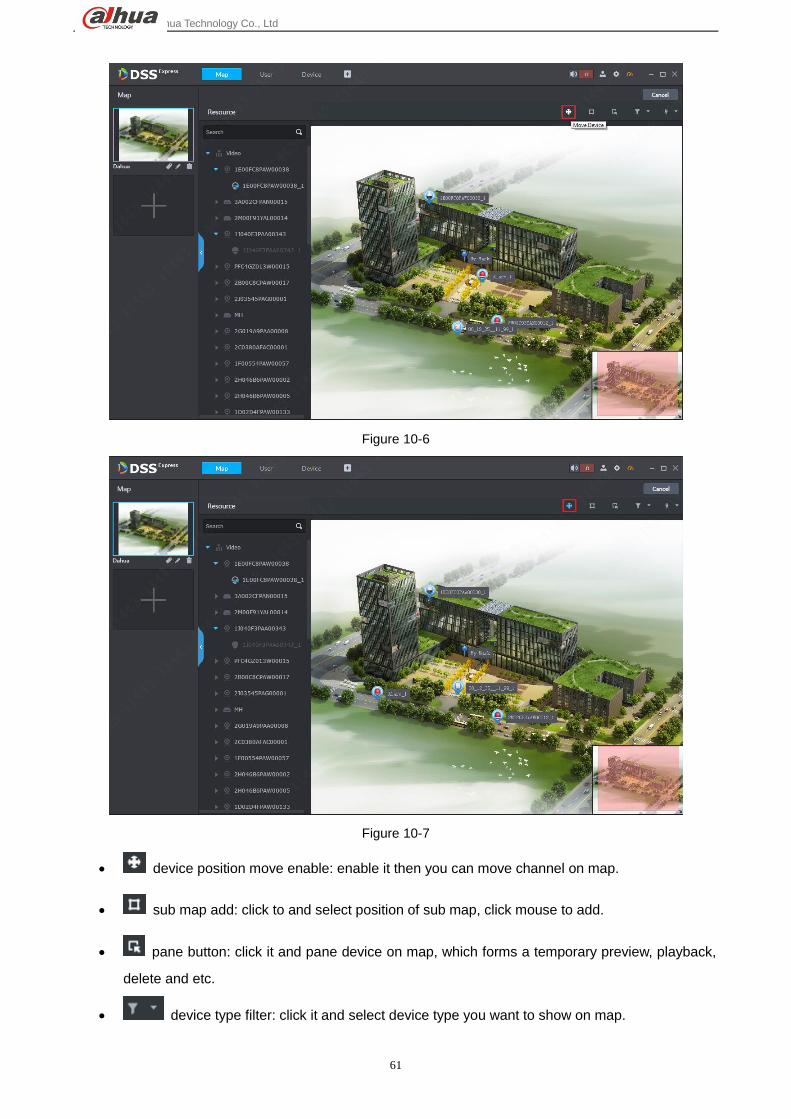
Dahua Technology Co., Ltd
61
Figure 10-6
Figure 10-7
device position move enable: enable it then you can move channel on map.
sub map add: click to and select position of sub map, click mouse to add.
pane button: click it and pane device on map, which forms a temporary preview, playback,
delete and etc.
device type filter: click it and select device type you want to show on map.

Dahua Technology Co., Ltd
62
mark and reset.
10.2 Add Sub Map One map can have multiple layers, and in map editing status, click button to add sub map:
Step 1. In map application mode, select map you want to add as sub map, click Edit to enter
map edit mode, see Figure 10-8.
Figure 10-8
Step 2. In edit mode, click sub map add button , see Figure 10-9.

Dahua Technology Co., Ltd
63
Figure 10-9
Step 3. Click add button, and the mouse will turn into a map icon. On map, select target
positon and left click mouse to add map, see Figure 10-10.
Figure 10-10
Step 4. After sub map is added, double click to enter sub map page. If you want to add
lower-level map in the sub map, the steps are same as above.

Dahua Technology Co., Ltd
64
Figure 10-11
Figure 10-12
10.3 Add More Maps DSS Express supports multiple maps, to add:
Step 1. In map application mode, select map you want to add sub map, click Edit to enter
edit mode, see Figure 10-13.

Dahua Technology Co., Ltd
65
Figure 10-13
Step 2. On the left, click Add button to add map, see Figure 10-14.
Figure 10-14
Step 3. In this page, set map name as you need, and select map picture, click OK. See
Figure 10-15.

Dahua Technology Co., Ltd
66
Figure 10-15
Step 4. After you complete adding of multiple maps, see Figure 10-16.
Figure 10-16
10.4 Map Application
10.4.1 Main Map Setup
When you add more than one map, you can set default map as main map, please select this map and

Dahua Technology Co., Ltd
67
click button in the figure below. After setup is complete, you can see a yellow icon. See Figure 10-17 and
Figure 10-18.
Figure 10-17
Figure 10-18
10.4.2 Pane Application
In map application, you can pane device to preview, playback.
Step 1. In map application, click pane button and in map pane area, it will generate a

Dahua Technology Co., Ltd
68
temporary list. In this list, you can select channel to preview and playback.
Figure 10-19
Step 2. After you select device, click preview button on map to preview.
10.4.3 Filter Device Type
On map, you can set display/no display of certain types of device. Click button to show
type selection. See Figure 10-20. If you do not want to show video channel, just uncheck it. See
Figure 10-21.

Dahua Technology Co., Ltd
69
Figure 10-20
Figure 10-21
10.4.4 Tool
In tool of map, you can set mark on map and restore default size of map. See Figure 10-22. In
map application page, click button and select content to execute, effect is in Figure
10-23.
Figure 10-22

Dahua Technology Co., Ltd
70
Figure 10-23

Dahua Technology Co., Ltd
71
11 Event
Event manager includes alarm scheme config and alarm processing. Firstly you must set alarm scheme
of actual channel you need in config.
11.1 Alarm Scheme Config Step 1. In Client homepage, click Config icon to enter config module, see Figure 11-1.
Figure 11-1
Step 2. Config page is shown. After you enter config module, select device/channel to set
alarm scheme, and click Event Configuration button to enter event config page.

Dahua Technology Co., Ltd
72
Figure 11-2
Step 3. In shown config page, select alarm type to config, and enable this type of alarm (red
box 2 in Figure 11-3), set alarm level and arm time. Set alarm link action according
to need. If no need, you can click OK to complete event setup (alarm scheme).
Figure 11-3
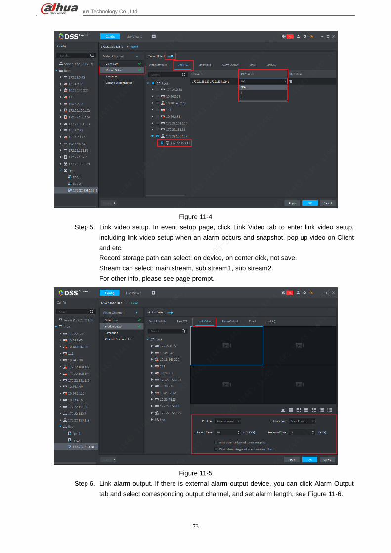
Step 4. Link PTZ. When an alarm occurs, you can select certain speed dome channel to turn to
its position for monitoring, as setting this speed dome to a certain preset, see Figure
11-4.
Dahua Technology Co., Ltd
73
Figure 11-4
Step 5. Link video setup. In event setup page, click Link Video tab to enter link video setup,
including link video setup when an alarm occurs and snapshot, pop up video on Client
and etc.
Record storage path can select: on device, on center dick, not save.
Stream can select: main stream, sub stream1, sub stream2.
For other info, please see page prompt.
Figure 11-5
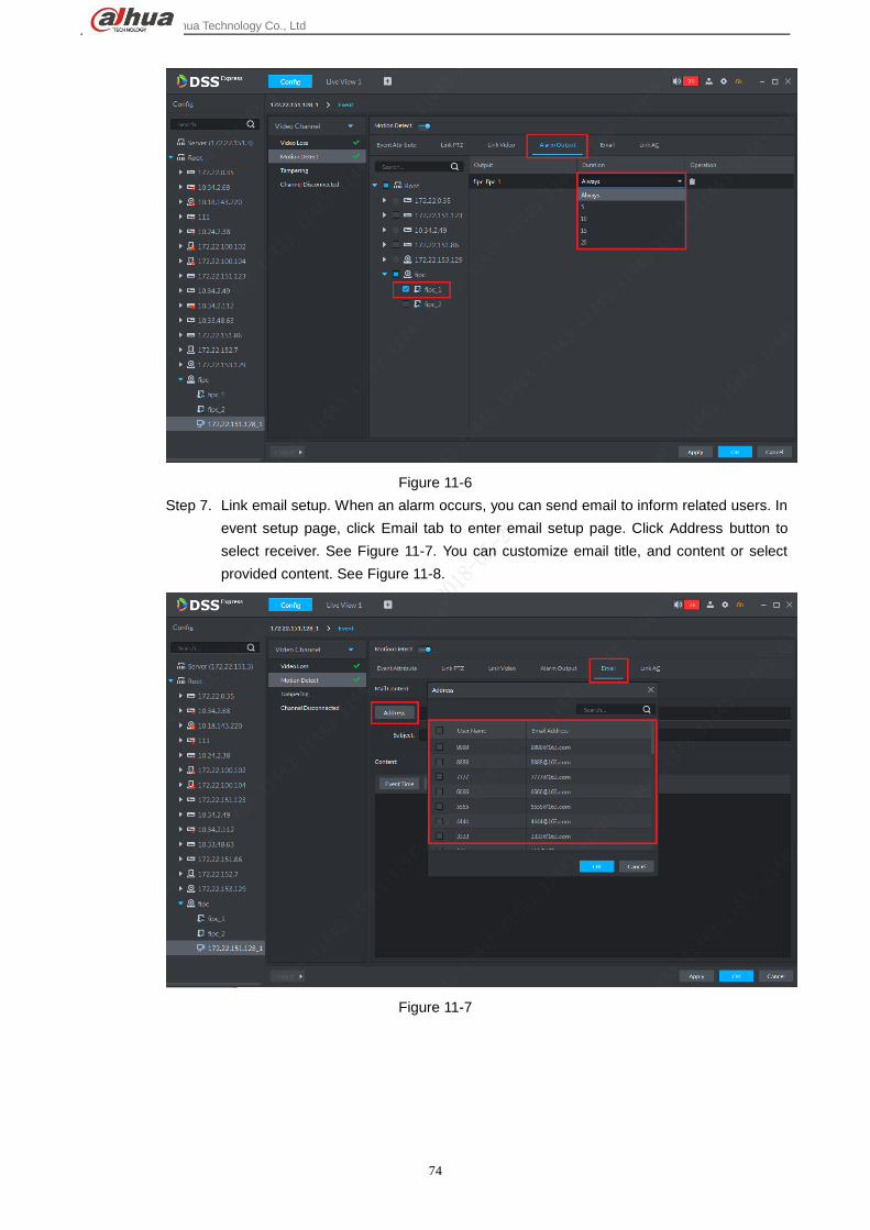
Step 6. Link alarm output. If there is external alarm output device, you can click Alarm Output
tab and select corresponding output channel, and set alarm length, see Figure 11-6.
Dahua Technology Co., Ltd
74
Figure 11-6
Step 7. Link email setup. When an alarm occurs, you can send email to inform related users. In
event setup page, click Email tab to enter email setup page. Click Address button to
select receiver. See Figure 11-7. You can customize email title, and content or select
provided content. See Figure 11-8.
Figure 11-7

Dahua Technology Co., Ltd
75
Figure 11-8
Step 8. Alarm link access control. When an alarm occurs, you can set open or close of multiple
access channel. Each channel can be set indepently. See Figure 11-9. After setup, click
OK button to complete.
Figure 11-9
Step 9. Event (alarm scheme)config is complete and see Figure 11-10. Be careful with alarm
type since each type must be separately set corresponding link, no batch setup
available.

Dahua Technology Co., Ltd
76
Figure 11-10
11.2 Alarm Manager
When an alarm occurs, you can click to process in Alarm at client navigation bar, as well as going to
Event manager module.
11.2.1 Alarm Prompt
When a new alarm occurs, at navigation bar in client, you can view obvious alarm prompt. Click alarm
quantity prompt to enter event manager page. See Figure 11-11.

Dahua Technology Co., Ltd
77
Figure 11-11
11.2.2 Real-time Alarm Processing
In event manager module you can process alarm: select alarm processing method (process, ignore,
transfer); view alarm linked view, snapshot and record. One-click to clear alarm info and etc.
Step 1. In Express Client homepage, click Event Center to enter event module, see Figure
11-12.
Figure 11-12

Dahua Technology Co., Ltd
78
Step 2. Real-time alarm is shown in Figure 11-13. Double click to view alarm details. Click
hand button in operation bar to claim the alarm. After alarm is claimed, the icon in
operation bar becomes an “eye”. If one alarm is claimed by user A, then other user
will not see it in alarm record, but it is visible in alarm history. However, other users
cannot process it in alarm history.
Figure 11-13
Step 3. Double click to view alarm detail. Default display of alarm detail include alarm time,
alarm type, alarm source (channel/device) and alarm level. See Figure 11-14. A
user can select alarm processing accordingly or a user can select process method
after viewing video, snapshot and record. The following example selects after
viewing all info.

Dahua Technology Co., Ltd
79
Figure 11-14
Step 4. In alarm detail page, click Live View tab to view alarm corresponding channel video
info, see Figure 11-15.
Figure 11-15
Step 5. In alarm detail page, click Snapshot tab to view alarm corresponding channel’s
snapshot info, see Figure 11-16.
Figure 11-16
Step 6. In alarm detail page, click Record tab to view alarm corresponding channel’s record,
see Figure 11-17.

Dahua Technology Co., Ltd
80
Figure 11-17
Step 7. According to actual condition, you can select processing method and you can enter
note.
Figure 11-18
Step 8. Temporary disarm. When you process alarm, you can click Temporary Disarm
button to set minutes of temporary disarm of this channel and this type of alarm.
See Figure 11-19.

Dahua Technology Co., Ltd
81
Figure 11-19
Step 9. Manually send email. When you process alarm, you can click Send Mail button to
manually send email to related person. You also can add email address, set title and
content of email. After you complete setup, click Send button.
Figure 11-20
11.2.3 History Alarm Search&Process
Step 1. In event center click tab to enter alarm manager history page. See Figure 11-21.
First please select channel to search and click first dropdown list and select alarm
type.

Dahua Technology Co., Ltd
82
Figure 11-21
Step 2. According to actual condition, select actual range of alarm search, see Figure 11-22.
Search range must be in the same month.
Figure 11-22
Step 3. Select alarm level, see Figure 11-23. If not select, all levels will be selected by
default.

Dahua Technology Co., Ltd
83
Figure 11-23
Step 4. Select to claim alarm. A user can search a user to claim this alarm according to
actual need, see Figure 11-24.
Figure 11-24
Step 5. Select alarm status, a user can select different statuses of alarm info, see Figure
11-25.

Dahua Technology Co., Ltd
84
Figure 11-25
Step 6. After you select criteria, click Search button to search alarm. Result is shown below.
Figure 11-26
Step 7. You can view or process searched alarm. Steps and method are same with
processing alarm. Please process referring to real-time alarm.

Dahua Technology Co., Ltd
85
12 Video Wall
12.1 Add Decode Device Before you add video wall and output video to wall, you must add decode device. Currently DSS Express
platform supports decode device: decoder and decode matrix. To add:
Step 1. In DSS Express client homepage, click Device to enter device manager module.
Figure 12-1
Step 2. In device manager page, click button, and then in pop-up box, select add
device method as by IP. For device type, select decoder or matrix.

Dahua Technology Co., Ltd
86
Figure 12-2
Step 3. Please follow instructions in page to complete info input and selection. Make sure
you have considered capability of decoder before you check Support Combination
box and please select decoder (direct, push, pull). After setup is complete, click Add
button.
Figure 12-3

Dahua Technology Co., Ltd
87
Step 4. Decoder device is shown below. Device status is red, meaning the device is offline.
Green means device is online. After decode device is added, you can see Decoder
option in device type.
Figure 12-4
12.2 Add Video Wall Step 1. In DSS Express client homepage, click Video Wall to enter device manager module,
see Figure 12-5.

Dahua Technology Co., Ltd
88
Figure 12-5
Step 2. In video wall page, click Video Wall dropdown list and click add video wall button to
add.
Figure 12-6
Step 3. In system pop-up box, fill in video wall name and note accordingly, see Figure 12-7.
Figure 12-7
Step 4. Select video wall number accordingly, and then place button of corresponding
number at random position on screen. See Figure 12-8. Click Next button to
continue.

Dahua Technology Co., Ltd
89
Figure 12-8
Step 5. If you want to set several screens into a combined screen, please hold Shift button
and select adjacent screens, then click Combine. After combined, you can see
Figure 12-10. Click Next button to continue.
Figure 12-9

Dahua Technology Co., Ltd
90
Figure 12-10
Step 6. If you want to clear video wall config, please click button. Click it than the entire
screen will be cleared.
Figure 12-11
Step 7. Enter decode channel binding setup. Drag decode channel on the left to
corresponding screen on the right. Be careful, if 4 screens are combined into one,
you must bind one decode channel to each of the 4 screens, so you cannot bind just

Dahua Technology Co., Ltd
91
one channel to the combined channel. One video wall can bind multiple channels of
decode device. After you complete binding, click Finish button.
Figure 12-12
Figure 12-13
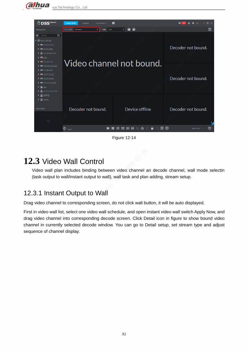
Step 8. In video wall control page, it shows the latest video wall.
Dahua Technology Co., Ltd
92
Figure 12-14
12.3 Video Wall Control Video wall plan includes binding between video channel an decode channel, wall mode selectin
(task output to wall/instant output to wall), wall task and plan adding, stream setup.
12.3.1 Instant Output to Wall
Drag video channel to corresponding screen, do not click wall button, it will be auto displayed.
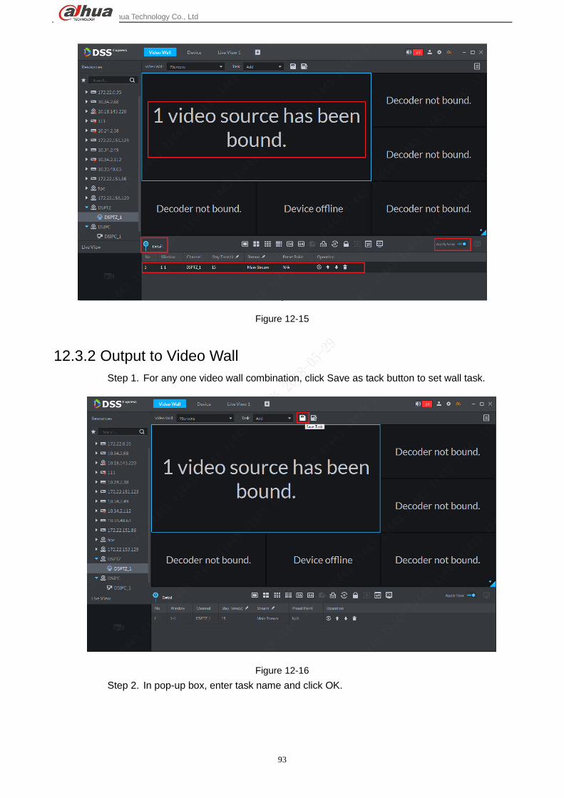
First in video wall list, select one video wall schedule, and open instant video wall switch Apply Now, and
drag video channel into corresponding decode screen. Click Detail icon in figure to show bound video
channel in currently selected decode window. You can go to Detail setup, set stream type and adjust
sequence of channel display.
Dahua Technology Co., Ltd
93
Figure 12-15
12.3.2 Output to Video Wall
Step 1. For any one video wall combination, click Save as tack button to set wall task.
Figure 12-16
Step 2. In pop-up box, enter task name and click OK.

Dahua Technology Co., Ltd
94
Figure 12-17
Step 3. Save current wall layout as task, and system will show this task by default. Now
instant wall switch will turn off. If a user updates bound video channel in this task
page, then he/she needs to click to control video wall.
Figure 12-18
Step 4. If you want to view live of a certain channel, please go to Detail and select
corresponding channel, click Play button. At the lower left corner, you can view live
of the channel.

Dahua Technology Co., Ltd
95
Figure 12-19
Step 5. Task modified based on current task allow user to click to save new task. Newly
saved task will be shown.
Figure 12-20
12.3.3 Wall Schedule
Wall schedule is setup of video wall task according to work time and length.
Step 1. In video wall page, click at the upper right corner to add schedule. In pop-up
page, click Add button to add schedule.

Dahua Technology Co., Ltd
96
Figure 12-21
Step 2. A user can select plan schedule or tour plan accordingly.
Differences between schedule and tour: schedule includes detailed start time and end time of each task
and if set task time is shorter than one day, user can set execution of other tasks as remaining time when
two tasks are already executed. Tour plan sets sequence of multiple tasks plus interval in between,
forming a cycle, without concept of remaining time.
Figure 12-22

Dahua Technology Co., Ltd
97
Step 3. Add schedule. Select schedule, enter schedule setup page. You can set execution
time of each task and remaining time task. After setup is complete, click Save.
Figure 12-23
Step 4. Successfully add schedule, see Figure 12-24.
Figure 12-24
Step 5. Add tour plan. Select Tour to add tour plan. A user can set task sequence and stay
length according to actual need. A user can adjust sequence in operation bar. Then
click Save.

Dahua Technology Co., Ltd
98
Figure 12-25
Step 6. After successfully saved, enable schedule switch.
Figure 12-26
Step 7. If you want to stop the schedule, click button. If you want to switch to other
schedule, click output plan button to enter schedule manager to switch.

Dahua Technology Co., Ltd
99
Figure 12-27
12.3.4 Control Function
12.3.4.1 Eagle Eye
When you set output channel in Client, if you cannot see screens clearly, you may zoom in certain part of
video wall via eagle eye function. Drag blue box and adjust its size to zoom in.

Dahua Technology Co., Ltd
100
Figure 12-28
12.3.4.2 One-click Clear Screen
It supports one-click to clear all info of current decode channel. Click this button to do so.
Figure 12-29
12.3.4.3 Lock Window
This lock window function is used when combined screen is open. If you lock window, then all windows
in this locked window cannot be moved. You must unlock window to move inner windows.

Dahua Technology Co., Ltd
101
Figure 12-30
Figure 12-31
12.3.4.4 Sync Play in Client
In video wall decoding window, it shows live of corresponding video channel. If the window does not
respond, please click mouse in other window and then click this window to activate it.

Dahua Technology Co., Ltd
102
Figure 12-32
Figure 12-33
12.3.4.5 Screen Switch
In Client, you can control switch to enable/disable some/all screens of decoding matrix.
Click in screen, and in pop-up box select screen to switch.

Dahua Technology Co., Ltd
103
Figure 12-34

Dahua Technology Co., Ltd
104
13 Person
13.1 Add Person
13.1.1 Add Department
Step 1. In Client homepage, click “Personnel Management “to enter user management
module, see 错误!未找到引用源。.
Figure 13-1
Step 2. On the left select root directory, click “Add”button to add department, see Figure
13-2.

Dahua Technology Co., Ltd
105
Figure 13-2
Step 3. In system pop up page, enter department name and click OK.
Figure 13-3
Step 4. After you add department, you can add user to corresponding department.
Figure 13-4

Dahua Technology Co., Ltd
106
13.1.2 Add A User
Step 1. In Client homepage, click “Personnel Management “to enter user management
module, see Figure 13-4.
Figure 13-5
Step 2. In User management page, click “Add”button to add user, see Figure 13-5.
Figure 13-6
Step 3. In system pop-up, fill in user info and please be noted user ID is mandatory. After
you complete filling, please switch to “Authentication “to set authentication.

Dahua Technology Co., Ltd
107
Figure 13-7
Step 4. Click page to enter authentication setting. Here you can set password,
add card no., collect fingerprint and etc.
Figure 13-8
Step 5. For password setting, click “Change” button , see Figure 13-9.

Dahua Technology Co., Ltd
108
Figure 13-9
Step 6. In the Figure 13-10, enter password of this user, click “OK”button.
Figure 13-10
Step 7. After you set password, click “Add “button to add card no., and in this page, enter
card no. of this user, click “OK” button to add card. You also can add card by reading
card on reader of access control device which you must click button
and select read card first.

Dahua Technology Co., Ltd
109
Figure 13-11
Step 8. After you add card, see Figure 13-12. To collect fingerprint, refer to step 9.
Figure 13-12
Step 9. Collect fingerprint, you must specify access control channel, and click collect
fingerprint button to select reader of access control channel. See

Dahua Technology Co., Ltd
110
Figure 13-13.
Figure 13-13
Step 10. After access control reader is selected, you shall manually select finger. Select a
specific finger via mouse, such as middle finger of left hand.
Figure 13-14
Step 11. After you select finger, as shown in system prompt, click add fingerprint button
and place your corresponding finger on reader you selected,

Dahua Technology Co., Ltd
111
remember to record three times (other fingers could be recorded as well). When you
hear a beep, rise your finger and place down again until three times of recording are
complete. You will receive a notice informing you all of three times of recordings are
dome and Client fingerprint status will change. See Figure 13-15 to Figure 13-16.
Figure 13-15
Figure 13-16

Dahua Technology Co., Ltd
112
Figure 13-17
Figure 13-18
Step 12. After fingerprint recording is complete, click “Authorize” button to
authorize access control channel, and you can select set door group in channel, see

Dahua Technology Co., Ltd
113
Figure 13-19
Figure 13-19
Step 13. Access channel is selected, then click “OK”in add user page, see user list below.
If there is authorized fingerprint and card, then icon will be blue.
Figure 13-20

Dahua Technology Co., Ltd
114
13.1.3 Batch Add
When you batch add, you can authorize card, but you cannot batch authorize password or
fingerprint. If you need, you can edit user right one by one.
Step 4. In Client homepage, click “Personnel Management “to enter user management
module, see Figure 13-21.
Figure 13-21
Step 5. In system pop-up page, click button to batch add new user.
Figure 13-22
Step 6. In system prompt page, enter user start ID and batch user quantity see Figure 13-23.

Dahua Technology Co., Ltd
115
When you complete filling, click “Next” button to enter batch issue card page. If you
do not have card info, you can click “Save and Exit” button to save
user info and exit.
Figure 13-23
Step 7. Enter batch issue card page, see Figure 13-24. Enter user card no. and click “Issue
Card” buttom to complete card issuring. Then you can enter next card no.
until you have alled all card no.

Dahua Technology Co., Ltd
116
Figure 13-24
Step 8. After card no. are filled in, please select validity time and expiration, then click “Next”
to enter.
Figure 13-25
Step 9. Enter batch authorize setup, you can select channel or door group with authorized
access control, see Figure 13-26,Click “Finish “button to complete adding and
setup.

Dahua Technology Co., Ltd
117
Figure 13-26
Step 10. After you add, user list is in Figure 13-27. Click button to delete user.
Figure 13-27
Step 11. If you want to edit user info, you can click at bottom to show user info and
edit info. See Figure 13-28. You can upload or change user photo, complete user
basic info, update user authorization method (Batch add card only, here you can set
password and fingerprint), and update access control channel.
Figure 13-28
Step 12. Edited info will take effective immediately. Click to refresh user list, see
Figure 13-29.

Dahua Technology Co., Ltd
118
Figure 13-29
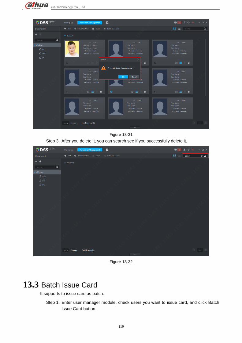
13.2 Delete User It supports delete one/multiple/all users:
Step 1. After you enter user manager module, check user to delete and click Delete.
Figure 13-30
Step 2. In pop-up box, click OK to delete.
Dahua Technology Co., Ltd
119
Figure 13-31
Step 3. After you delete it, you can search see if you successfully delete it.
Figure 13-32
13.3 Batch Issue Card It supports to issue card as batch.
Step 1. Enter user manager module, check users you want to issue card, and click Batch
Issue Card button.

Dahua Technology Co., Ltd
120
Figure 13-33
Step 2. In this page, enter card no. (or swipe card at reader), and then click Issue Card
button to issue card.
Figure 13-34
Step 3. Issue card to all designated users, so these users do not need authorization of
access control channels. Click Save and Exit.

Dahua Technology Co., Ltd
121
Figure 13-35
Step 4. If you want to authorize user with access control right, please click Next button to
enter next step. In access control channel page, select channel or set access
control group, and then click Finish button.
Figure 13-36

Dahua Technology Co., Ltd
122
14 Access Control
14.1 Add Access Control Device Log in DSS Express Client,and in management bar, enter device management module, you
can add, edit and delete access controller, steps:
Step 1. In Express Client homepage find management bar, click “Device” module to enter
device management, see Figure 14-1.
Figure 14-1
Step 8. Device management page shown, click “Add” button to add device manually.

Dahua Technology Co., Ltd
123
Figure 14-2
Step 9. See Figure 14-3. First select device register mode to be IP Address, and set device
category to be “Access”.
Figure 14-3
Step 10. According to page requirement, fill in device info, including:device name, IP
address, port no. (default is 37777), username and password. If you have not
created organization node and device is under root node Video 下,see Figure 14-4.
Confirm info and click “Add” button to add.

Dahua Technology Co., Ltd
124
Figure 14-4
Step 11. Access control device is shown below. If device network communication is normal,
server will auto get device type and channel info.
Figure 14-5
14.2 Time Template&Holiday Group
14.2.1 Time Template
Step 1. In Client homepage, click “Access Conrtol” to enter access control module. See
Figure 14-6 to enter access control module.

Dahua Technology Co., Ltd
125
Figure 14-6
Step 2. Select time template tab ,and then in the page, click add time template button
to add time template.
Figure 14-7
Step 3. In time template setup page, enter name. On time axis, draw out period you need,
see Figure 14-8. A pen sign is draw button, and eraser sign is clear button. When
you are done, click “OK” button to complete.

Dahua Technology Co., Ltd
126
Figure 14-8
Step 4. Time template list update is shown below.
Figure 14-9
14.3 Access Control Console In console, you can unlock, lock, open video(must set linked channel in door config first)and
etc. plus right click to remotely unlock/lock, set door and etc.

Dahua Technology Co., Ltd
127
14.3.1 Door Config
Door config module can set door channel name.
Step 1. Enter Access Control module console, on the left, select one access control channel
and right click mouse. In pop-up menu, select Door Config to enter config page. See
Figure 14-10.
Figure 14-10
Step 2. Access control channel config page is shown in Figure 14-11. Please set
parameters accordingly, and click “OK” button to complete setup and enter config
homepage.

Dahua Technology Co., Ltd
128
Figure 14-11
Step 3. In config homepage, click Resource Bind to enter video channel bind page. See
Figure 14-12.
Figure 14-12
Step 4. Video channel bind page is shown, please select video channel and click “OK”
button.

Dahua Technology Co., Ltd
129
Figure 14-13
14.3.2 Access Control Channel Control
Step 1. Unlock door. Enter access control module console, on the left, select access control
channel and then on the right, click unlock button ,it will generate corresponding
unlock record. See Figure 14-14 and Figure 14-15.

Dahua Technology Co., Ltd
130
Figure 14-14
Figure 14-15
Step 2. Within certain time (can be set in door config, default is 5s, here uses 10s), door
will auto lock and a record is created in event column. See Figure 14-16.

Dahua Technology Co., Ltd
131
Figure 14-16
Step 3. Lock door. When a door is open, click unlock button to unlock it. See Figure
14-17.
Figure 14-17
Step 4. Unlick effect and event record is in Figure 14-18.

Dahua Technology Co., Ltd
132
Figure 14-18
14.3.3 Event Details
Step 1. In event list, select one record and click to view details,include:event info, live
video, snapshot, record. Live video must be bind video channel to door in door
config first before you can view live here. You must link video in scheme example
management first before you can snapshot and record here. Please refer to scheme
management chapter.。
Figure 14-19

Dahua Technology Co., Ltd
133
Figure 14-20
14.3.4 Global Control
Global control main function is to select one or more access control channel and NO/NC and
restore to normal. Steps:
Step 1. In access control module console, on the left click config button to select channel,
button is in Figure 14-21.
Figure 14-21
Step 2. In pop-up channel list, select channel for global control, see Figure 14-22 and click
“OK” button to take effect.

Dahua Technology Co., Ltd
134
Figure 14-22
Step 3. Currently front door is closed, and you can click NO button to unlock it. This
operation must be operated with password, so please enter password of current
user in system box, and click “OK” button. (After global control unlock, the door will
not close automatically after set time, instead please manually click replay or click
button to close door.)

Dahua Technology Co., Ltd
135
Figure 14-23
Step 4. On the right, in access control channel list, you can see selected door status
become open status. See Figure 14-24.
Figure 14-24
Step 5. Click NC button, and follow system instructions to enter current username password,
click “OK”button to start. See Figure 14-25.

Dahua Technology Co., Ltd
136
Figure 14-25
Step 6. Exit global control, please click to restore normal via button “Resume” .
14.3.5 Scheme Management
Scheme management function includes setup of access control channel’s alarm type and you
can determine alarm priority, scheme work period, link PTZ preset, linked video open in preview
window, linked snapshot and record, linked alarm output, alarm email sending, linked access
control channel in NC/NC status and etc.
Warning:
Every alarm type in link config shall be separately set, since you cannot set them together as a
batch.
Step 1. Enter access control module console, and on the left, select one access control
channel and right click mouse, in pop-up menu, select Door Config to enter config
page. See Figure 14-26.

Dahua Technology Co., Ltd
137
Figure 14-26
Step 2. Enter event config page, first please select alarm type, and then enable alarm ,
set alarm level, select alarm arm work time(select time template), see Figure 14-27.
After you execute, you also can select other alarm type and follow the same steps to
set. Each alarm type can be set to different levels and arm time.
Figure 14-27
Step 3. Link PTZ preset config. When event property config is complete, please go to event
config page, and select Link PTZ tab. See Figure 14-28. Select one speed dome
channel, and then select the preset which speed domes rotated to when event

Dahua Technology Co., Ltd
138
occurred. If preset list is null, you can skip this step and click edit scheme to set PTZ
link.
Figure 14-28
Step 4. Link video-category setup, please select Link Video tab, see Figure 14-29. You can drag video
channel into preview window to preview video. You can select if to save record when event
occurs and stream type, time to save plus whether to enable snapshot, open video in preview
window and etc. Please set accordingly.
Figure 14-29
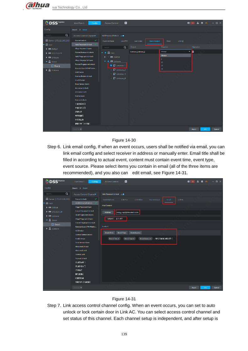
Step 5. Link alarm output channel, if alarm output channel connects to buzzer alarm or
other alarm devices, you shall let the system auto enable alarm at occurrence, and
set alarm length, see Figure 14-30.
Dahua Technology Co., Ltd
139
Figure 14-30
Step 6. Link email config, If when an event occurs, users shall be notified via email, you can
link email config and select receiver in address or manually enter. Email title shall be
filled in according to actual event, content must contain event time, event type,
event source. Please select items you contain in email (all of the three items are
recommended), and you also can edit email, see Figure 14-31.
Figure 14-31
Step 7. Link access control channel config. When an event occurs, you can set to auto
unlock or lock certain door in Link AC. You can select access control channel and
set status of this channel. Each channel setup is independent, and after setup is

Dahua Technology Co., Ltd
140
complete, click “OK”. See Figure 14-32.
Figure 14-32
Step 8. Scheme is shown in Figure 14-33.
Figure 14-33
14.4 Door Group Door group and door rule are non-standard config, and user can select to set or not.
Step 1. In Client homepage, click “Access Conrtol”to enter access control module, see

Dahua Technology Co., Ltd
141
Figure 14-34.
Figure 14-34
Step 2. Click “Access Conrtol”tab to enter door group&rule setting page, in Door Group
page click “Add”button, see Figure 14-35.
Figure 14-35
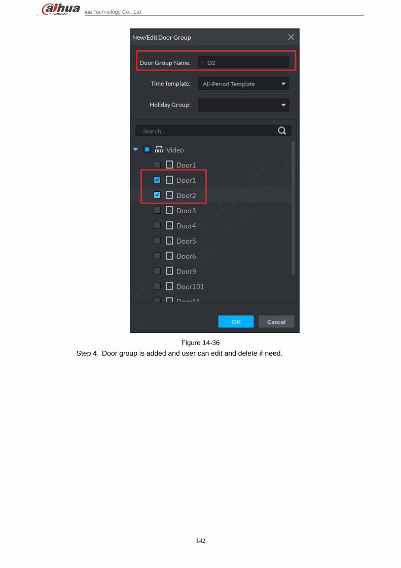
Step 3. Door group setting page is shown. Please follow instructions to fill in door group
name, select time template(not required),select channel, click “OK” button to save.
Dahua Technology Co., Ltd
142
Figure 14-36
Step 4. Door group is added and user can edit and delete if need.

Dahua Technology Co., Ltd
143
Figure 14-37
14.5 Advanced Function
14.5.1 First Card Unlock
First card unlock node:after you set first card unlock only this first user swipe card, then other
users may swipe card to unlock door. You may set more than one first card, as long as one first
user swipes card, others can swipe card. Steps:
Step 1. Enter access control control module, and select advanced function tab, in “First
Card Unlock” tab, click Add button to add first card unlock scheme, see
Figure 14-38.

Dahua Technology Co., Ltd
144
Figure 14-38
Step 2. Select access control channel(select one only), time, door status, user with first
card unlock (support multiple choice)in add page,set and click “OK”to add.
Scheme takes effect.
Figure 14-39
Step 3. First card unlock scheme list is sown below, in this page the user can select to
enable/disable this scheme, or edit and delete scheme.

Dahua Technology Co., Ltd
145
Figure 14-40
14.5.2 Multiple Card Unlock
Multiple card unlock note: for a certain access control channel, more than one group of user shall swipe
card in set sequence in order to unlock it and you can set valid number of user of each group as
changing valid unlock user number in the group. Max of 4 groups and accumulated valid user cannot
exceed 5. Steps:
Step 1. Enter access control module and select advance function tab, click “Multi-Card
Unlock”tag to enter multiple card setup page. When first time set, please add user
group first. In this page, click “Add user group”button to add user
group.

Dahua Technology Co., Ltd
146
Figure 14-41
Step 2. In the system, click “Add”button to add.
Figure 14-42
Step 3. In shown page, set group name, and check group member in corresponding
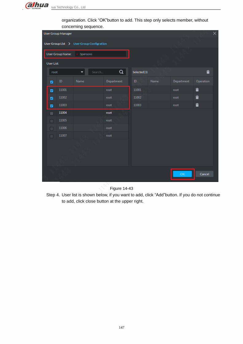
Dahua Technology Co., Ltd
147
organization. Click “OK”button to add. This step only selects member, without
concerning sequence.
Figure 14-43
Step 4. User list is shown below, if you want to add, click “Add”button. If you do not continue
to add, click close button at the upper right.

Dahua Technology Co., Ltd
148
Figure 14-44
Step 5. Click “Add”button to continue to add 3 groups, and you can see Figure 14-45 when
complete.

Dahua Technology Co., Ltd
149
Figure 14-45
Step 6. Click user group adding, and return to multiple card setup page. Click “Add” to add
multiple card unlock scheme. See Figure 14-46. Please select access control
channel in list.

Dahua Technology Co., Ltd
150
Figure 14-46
Step 7. Access control channel is selected and then select user group. Adjust group
sequence, valid user in each group, unlock method (card, password, fingerprint)
and etc. After setup is complete, click “OK”button to complete. See Figure 14-47.
Figure 14-47
14.5.3 Anti-passback
Anti-pass back note:Set single/multiple user unlock path, so these users can only unlock is this
sequence.
If you have set 1 2 3 anti-pass back, and then swipe 1 and then swipe 3 ,it will trigger
anti-pass back alarm(after general access control alarm, you can still unlock in set sequence),
then swipe 1 2 3 will not successfully unlock, instead you must wait until reset time ends before
you can swipe card to unlock again.
Steps:
Step 1. After you enter access control module, select advanced function tab, in “Anti-Pass
Back”tag, click Add button to add anti-pass back scheme, see Figure 14-48.

Dahua Technology Co., Ltd
151
Figure 14-48
Step 2. In Add page, select access controller, set scheme name, and follow instructions and
your need, set door group quantity and reader in each group. See Figure 14-49.
After setup is complete, click “Next” button to enter user selection page.

Dahua Technology Co., Ltd
152
Figure 14-49
Step 3. In user selection page, please select use of this setup (multiple users are OK), and
then click “OK”button to complete.

Dahua Technology Co., Ltd
153
Figure 14-50
Step 4. After adding is complete, see list in Figure 14-51.

Dahua Technology Co., Ltd
154
Figure 14-51
14.5.4 Inter-lock
Inter-lock function node:General access control is in-group inter-lock, and centralized controller
is group-group inter-lock. General access control:In inter-lock group, as long as one door is
open, you cannot open other doors. Centralized access control:channels in the same group
are not related, so you can open them as you wish, however, as long as one channel in a
group is open, you cannot open channel in other groups.
The following takes centralized controller as an example:
Step 1. After you enter access control module, select advanced function tab, in
“Inter-Lock”tab, click New button to add inter-lock plan. First please select
access control device in Device list. See Figure 14-52.

Dahua Technology Co., Ltd
155
Figure 14-52
Step 2. In Add page, set inter-lock name, select period of plan, and add access control in
each door group. If the default two groups do not meet you need, you can click “Add”
button to add more groups. See Figure 14-53. Click “OK”to complete.
Figure 14-53
Step 3. Successfully added plan is shown in Figure 14-54.

Dahua Technology Co., Ltd
156
Figure 14-54
14.5.5 Remote Verification
Remote verification function note:set remote verification device, and within set period, when a
user unlocks door via card, fingerprint, password and etc., he/she must click confirm box in
Client to confirm unlock before he/she can unlock, steps:
Step 1. Enter access control module and select advance function tab, in “Remote
verification”tab, click New button to add remote verification plan, see Figure
14-55.
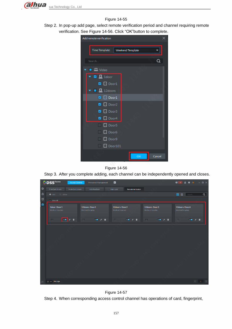
Dahua Technology Co., Ltd
157
Figure 14-55
Step 2. In pop-up add page, select remote verification period and channel requiring remote
verification. See Figure 14-56. Click “OK”button to complete.
Figure 14-56
Step 3. After you complete adding, each channel can be independently opened and closes.
Figure 14-57
Step 4. When corresponding access control channel has operations of card, fingerprint,

Dahua Technology Co., Ltd
158
password and etc., the Client will pop up box, so you can select to unlock or ignore it.
Click corresponding button and the box will disappear.
Figure 14-58

Dahua Technology Co., Ltd
159
15 ANPR
15.1 Add ANPR Device Step 1. In DSS Express Client homepage, click Device to enter device manager module.
Figure 15-1
Step 2. In device manager page, click button, and then in pop-up box, select method to
add device as by IP. Select ANPR for device type. According to instructions, fill in each
info. Click Add button.

Dahua Technology Co., Ltd
160
Figure 15-2
Step 3. After you add device, device list is shown below. Red is offline. Green is online.
Figure 15-3
15.2 Picture Storage Keyboard Setup You must set corresponding storage disk of ANPR channel before entering road surveillance application.
If you do not set storage disk, all pictures from road surveillance will not be shown. See Ch 7.

Dahua Technology Co., Ltd
161
15.3 Road Surveillance Application
15.3.1 Passed vehicle
Step 1. In Express Client homepage, click Entrance to enter road surveillance application.
Figure 15-4
Step 2. In this page, select tab to enter road surveillance application. Default is single
window of a electronic map, you can manually change number of windows.

Dahua Technology Co., Ltd
162
Figure 15-5
Step 3. In this shown page, click button to select ANPR channel of passed vehicle.
Figure 15-6
Step 4. In system pop-up page, select corresponding ANPR channel.
Figure 15-7
Step 5. After you select channel, system will mark the selected channel, and show the latest
picture of passed vehicle in picture scrolling area.

Dahua Technology Co., Ltd
163
Figure 15-8
Step 6. Double click picture to view picture detail, including plate no., snapshot time, ANPR
channel name, logo, vehicle color and etc.
Figure 15-9
Step 7. Refresh pause. In actual application, if you want to pause refresh of passed vehicle
record, click button shown below.

Dahua Technology Co., Ltd
164
Figure 15-10
15.3.2 Passed Vehicle Record Search
In actual application, you can search record of passed vehicle.
Step 1. In road surveillance application, click button to enter search page.
Figure 15-11
Step 2. Enter passed vehicle record search page. First select channel to search accordingly,
and then select search time, plate no., plate color, vehicle type, logo, vehicle color,
speed and etc. Click Search button.

Dahua Technology Co., Ltd
165
Figure 15-12
Step 3. Result is shown below. There are thumbnail and list modes of display. Here uses
thumbnail.
Figure 15-13
Step 4. Double click picture to view details, including: zoom in vehicle picture, plate no.,
snapshot time, ANPR channel name, lane, speed, plate color, vehicle type, logo,
vehicle color.

Dahua Technology Co., Ltd
166
Figure 15-14
Step 5. If the system recognize some mistake in vehicle detail, you can click button
to manually change.
Figure 15-15
Step 6. Editable content: plate no., plate color, vehicle type, logo, vehicle color. Click Save
button to save and if you want to cancel edited content, click Cancel.

Dahua Technology Co., Ltd
167
Figure 15-16
15.3.3 View Passed Vehicle Record
You must set general record plan for the ANPR channel before you can view passed vehicle record.
Method of setup is similar with video channel, see Ch 6.3.
In passed vehicle record search result, select of corresponding passed vehicle record or click Play
button in detail to view scenes before and after snapshot.
Figure 15-17
15.3.4 Export Passed Vehicle Record
A user can export some or all of passed vehicle record.

Dahua Technology Co., Ltd
168
Step 1. In passed vehicle record search result, check record you want to export, click Export
button. You can export all records.
Figure 15-18
Step 2. Please select storage path following system prompt. You can see the following
figure is successful.
Figure 15-19