Huanyang YM 1500W VFD.pages - PrintNC Wiki
10
Basic setup of 0.8KW SPINDLE & VFD 220V (Australian Voltage example) Warning - High voltage! Always use a qualified electrician to connect this unit. Use at your own risk! Please check your countries voltage and electrical codes of practice first and seek a qualified electrician for safe connection. Always unplug (disconnect and isolate) from mains power when working on circuits. Read and understand the manuals safety instructions that should of came with your VFD inverter. This is your responsibility, so do the right thing, be safe and live.
-
Upload
khangminh22 -
Category
Documents
-
view
0 -
download
0
Transcript of Huanyang YM 1500W VFD.pages - PrintNC Wiki

Basic setup of 0.8KW SPINDLE & VFD 220V (Australian Voltage example) Warning - High voltage! Always use a qualified electrician to connect this unit. Use at your own risk! Please check your countries voltage and electrical codes of practice first and seek a qualified electrician for safe connection. Always unplug (disconnect and isolate) from mains power when working on circuits. Read and understand the manuals safety instructions that should of came with your VFD inverter.
This is your responsibility, so do the right thing, be safe and live.

Cheapish Chinese Variable Speed Brushless Spindles and Variable Frequency Drivers or Inverters (VFDs) are common and easily available on the internet and are an attractive alternative to the cheaper trim routers often used by default on hobby CNCs… Like with most things there are pros, cons and dangers. Note: Make sure you get a spindle and VDF suitable for your countries Voltage. Cons: • More expensive then a router, especially when adding up the extras needed like the
cost of a qualified electrician, quality shielded wire, submersible pump, water lines, water container and mounting options. Did I say the free shipping takes forever!
• Unlike a router that just needs to be securely mounted to your CNC, plugged into a power point and turned on; these Spindle VFD combos need to be wired up and programmed first otherwise you will break it or yourself before you cut anything.
• Heavy compared to routers, so your machine needs to be strong enough to move one. You might be able to shoe horn a big block V8 into a Mini Moke, giving incredible power in a straight line, but what’s going to happen at the first corner?
• No protective earth on the spindle, so they are a potential death trap in the event of a short circuit or electrical fault in the spindle, it being unlikely to trigger your protective RCD (Residential Current Device) which are thankfully required by law in most countries now. Make it a regular habit to press the test button.
• Electrically these are noisy “critters”… so RF interference will be a problem if suitable shielded cable isn’t used or grounded properly; destroying the reception on your radio but more importantly, playing havoc with control boards, low voltage signals and computers in the system along with annoying your neighbours.
Pros: • Selectable speeds, that remain closer to the constant set speed. So choosing the
best feeds and speeds for your machine is some what easier to predict and replicate; unlike a brushed motor router… with their guesstimate speeds that tends to bog down losing speed when cutting. VFD’s have more torque and can operate at slower speeds then routers; though in reality the lowest speed for a water cooled spindle is ~ 6000RPM as torque drops off rapidly below this speed. A air cooled spindle dies in “smoke, flames and much sadness” below 7200RPM.
• Less runout then routers, leading to more accurate cuts and less chatter. • Quieter then a router. Well this one is pretty irrelevant once you start cutting
something like aluminium or turn on the shop vac. If you've only used a router before, it is one of the first things you’ll notice along with smoothness.
• I’ve got to say it… they just look “way cooler in a minimalist kind of way”… but need to be treated with some respect.
Air or WaterWater has better heat absorbing qualities then air by far, so a water cooled spindle will by default, run cooler then an air-cooled spindle, allowing it to run longer at lower speeds, without going into thermal meltdown. It is important to note, that an air cooled spindle needs to be spinning at 7200 RPM or greater to push enough air through the motor, to prevent the internal wire insulation melting down and destroying your spindle. The sound from its fan pushing air down through the motor blasting dust all over your workshop is also going to be louder then a water cooled spindle.
Size mattersIt’s pretty pointless to go the biggest spindle you can get unless you’ve got a machine that can cope with it. Lets face it, most hobby CNCs wont be able to push a big heavy powerful spindle through your work piece, so going bigger is only going to make your machine less capable. If you want to utilise the openbuilds spindle mount you're limited to 65mm diameter spindles (using some shimming). So you're looking at 0.8kw water/air cooled spindles and some 1.5kw air cooled spindles with ER11 collets and mill bits with shanks ranging from 7mm to 1mm with appropriate collets.

All wiring/testing needs to be done, disconnected (unplugged and isolated) from the power source (mains). “Death is final”
Add missing “protective earth” to spindle As it comes from the factory, pin 4 (earth) on the spindle motor is not connected to the metal body of the spindle. If you don’t believe me test it for continuity between pin 4 and the metal body of the spindle.
To fix, remove the top plate of the spindle by undoing the four outside screws, being careful not to lose the two o-rings seals under the water inlet/outlet. Add a short length of wire (green wire in picture) by replacing one of the M3 screws holding the plug in place with a longer one so you can attach a small ring terminal tightly between two M3 nuts on the inside. Solder the other end of wire to pin 4 solder lug of the plug; using wire at least the same gauge as your spindle cable.
Reattach the top plate, making sure the o-rings are seated and lined up with the water channels in the body and the wires are clear and not crushed between the body and top plate.
Wiring Spindle to VFD large amounts of RF are generated between your VFD and spindle causing interference to electronics, which can be a major problem in a CNC machine. This can be easily minimised by using quality shielded cable to keep the RF noise in and returning it back to it’s source (the drive). The best way to contain this noise, in this case, is to connect the shield at both ends to the VFD ground. Your bearings will last longer to.
Some of the termination guides from the manufacturers of quality shielded cable are useful to work out the best way to terminate your shielded cable to your VFD. On the motor side clamp the exposed trimmed shielding under the spindle plug’s clamp; so it flows through the metal body of the plug, then through the longer M3 screw, short green wire to pin 4 on the inside of the spindle and back through the ground wire (green with yellow stripe) to the VFD ground terminal.
Please make sure your ground is correct… pin 4 on both sides of the spindle plug to ground on VFD; as attaching the ground to any other terminal is highly dangerous. So make sure the ground wire is the correct colour and is obvious to others (green with yellow stripe). Test for continuity from the metal body of the spindle to VFD ground, U, V and W terminals. U, V and W should all have OL readings, while VFD ground to metal body of spindle will have continuity. Check then double check before attaching to the mains power.
You will need 4 core (braid) shielded cable 0.75mm2 (~18 AWG) to 1.0mm2 being a good option for a 0.8kw to 1.5kw spindle, 1.5mm2 cable is the limit that can be terminated to the metal aviation plug on the spindle if your creative. Just make sure it is flexible if you intend to run it through a cable chain; the other cables running through the chain will need to be shielded as well. An example of flexable cable.
Wiring Mains to VFD Shock and another useful link… to start your research. I just used a old 10A computer power lead in good condition (tested) and terminated with bootlace terminals to the VFD screw terminals to make a good connection without stray wires to the screw terminals of the VFD. I connected the 240V submersible water pump to the VFD AC power input screw terminals so it is always running when the VFD has power going to it.
IMPORTANT PARAMETERS TO SET BEFORE RUNNING YOUR SPINDLE FOR THE FIRST TIME
Wiring all good? Yes! Turn off computers and Test RCD is working? Yes! Plug it in.
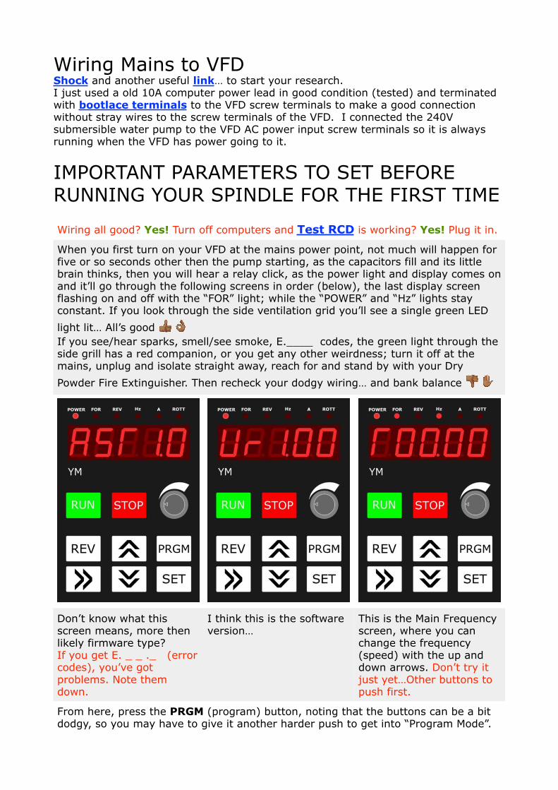
When you first turn on your VFD at the mains power point, not much will happen for five or so seconds other then the pump starting, as the capacitors fill and its little brain thinks, then you will hear a relay click, as the power light and display comes on and it’ll go through the following screens in order (below), the last display screen flashing on and off with the “FOR” light; while the “POWER” and “Hz” lights stay constant. If you look through the side ventilation grid you’ll see a single green LED
light lit… All’s good ! " If you see/hear sparks, smell/see smoke, E.____ codes, the green light through the side grill has a red companion, or you get any other weirdness; turn it off at the mains, unplug and isolate straight away, reach for and stand by with your Dry
Powder Fire Extinguisher. Then recheck your dodgy wiring… and bank balance # $
Don’t know what this screen means, more then likely firmware type? If you get E. _ _ ._ (error codes), you’ve got problems. Note them down.
I think this is the software version…
This is the Main Frequency screen, where you can change the frequency (speed) with the up and down arrows. Don’t try it just yet…Other buttons to push first.
From here, press the PRGM (program) button, noting that the buttons can be a bit dodgy, so you may have to give it another harder push to get into “Program Mode”.
� ��

You should end up in Pd000, with the last digit flashing. Use the up and down arrows to move through the different programs. If not at Pd000 get it to Pd000 and press SET. If you dawdle too long, it will go back to the start screen and you will have to start over again.
In the parameters of Pd000, the 0 digit will be flashing. This is the currently set parameter for this Pd, if you press set now (don’t) it will go to the next Pd up, as it is already set.
Use the up button to change it to [1].
Now that this parameter has been changed to [1], press SET, to set it in memory.
End will appear for a second to let you know your made a change, then it will go to the next highest Pd, in this case Pd001
Now that you are at Pd001 you could try to change its settings, but you wont be able to, as you’ve locked the parameters by setting Pd000 to [1]. Get back to Pd000 with down button.
Now that your in Pd000, press SET and change it back to [0] so you can proceed with the other settings.
Trick: >> button moves the input point when changing settings.
�
�
�
�
�
�

Pd000 set to [0] Factory setting Parameter Lock Set to [0] unlocks the program (function) parameters (settings). This needs to be done first so you can change the following program parameters. Set back to [1] to lock the program parameters “after you have finished changing the ones that need to be changed”, so you or someone else doesn’t inadvertently change your setting by randomly pushing buttons.
Pd013 set to [8]*Last resort Factory defaults *Use this setting now if you’ve been mucking around and everything is mucked up, hopefully you haven’t done too much damage yet! Set to [8] to get back to the factory defaults. Noting that factory defaults are a starting point and are not a safe point to start running your spindle. It might be a good idea to go through all the program parameters first before setting this and while your at it record them on paper before changing to factory defaults; just to see if they differ from what’s in the manual… to be safe.
If you’re following this guide from the beginning, skip to Pd001.
Pd001 set to [0] Factory setting Command source Set to [0] to control the spindle with the front control panel. Set to [1] to control the spindle with external controls wired to the screw terminals. Set to [2] to control the spindle using RS-485 communication port.
Pd002 set to [1] Speed (frequency) control source Set to [0] to control the spindle speed with the front control panel digital up and down arrows. Set to [1] to control the spindle speed with analog speed dial (potentiometer); that’s if your VFD model has it on the front control panel. Note that you will lose the manual speed control with the digital up and down arrows with this setting. Set to [2] to control the spindle with an RS-485 communication port. This is where your control board talks to your VFD to do cool stuff like automatically change speeds, run and stop your spindle, through G-code commands. For the moment we wont go into it to keep things simple, but mainly because I don’t have a good understanding myself.
Pd003 set to [120] Main Frequency (Hz) If you set Pd002 to [0] this is the Hz (speed) your spindle will start off at. This speed can be changed with the up and down arrows during operation of the spindle and the last speed (Hz) set, will be remembered and added here. Some suggest setting this to 400Hz (full speed), but for your first run it is better to start at a more conservative, but safe speed and slowly increase it to let your bearings have some time to settle in.
Pd004 set to [400] Base Frequency (Hz) This is the Frequency etched on your spindle motor.

Pd005 set to [400] Maximum Operating Frequency (Hz) This is the maximum frequency you can run your spindle with the speed controls.
Pd006 to Pd010 are to set the torque curve of the motor, the following setting are for a constant torque curve.
Pd006 set to [2.5] Factory setting Intermidiate Frequency (Hz)
Pd007 set to [0.5] Factory setting Minimum Frequency (Hz)
Pd008 set to [220] Factory setting for 220V VFD Maximum Voltage (V)
Pd009 set to [15] Intermediate Voltage (V)
Pd010 set to [8] Minimum Voltage (V)
Pd011 set to [100], Air cooled set to [120*] Frequency Lower Limit (Hz) SAFE LOWER LIMIT FREQUENCY (SPEED) This is the starting frequency when the run button is pressed, when every thing else is setup, your spindle will ramp up to this frequency which is 6000 RPM that is, if the speed dial is fully turned anticlockwise. *If you have a “Air Cooled Spindle, set it to 120Hz” (7200 RPM) to be safe or you will burn out your spindle in about ten seconds after pressing run, as there will not be enough air flow to cool it down. So in effect if you have a air cooled spindle then your speed range is 7200 RPM to 24000 RPM. Don’t run your water cooled spindle without water pumping through it or you will burn it out as well, it will just take longer for you to realise it, as the magic smoke is held in. If you get the magic smoke, the spindle stops or runs erratically unplug it immediately from the power source before touching anything to avoid shock.
Skip to Pd014
Pd014 set to [12] Acceleration Time (1) Ramp up time in seconds to go from 0 Hz (0 RPM) to 400 Hz (24000 RPM) this is a safe time when starting out for a motor of this type.
PD015 set to [12] Deceleration Time (1) Ramp down time in seconds to go from 400 Hz to 0 Hz. So same as above
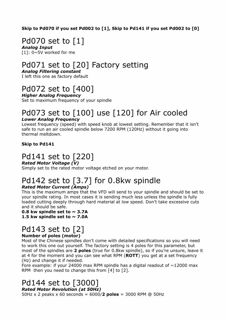
Skip to Pd070 if you set Pd002 to [1], Skip to Pd141 if you set Pd002 to [0]
Pd070 set to [1] Analog Input [1]: 0~5V worked for me
Pd071 set to [20] Factory setting Analog Filtering constant I left this one as factory default
Pd072 set to [400] Higher Analog Frequency Set to maximum frequency of your spindle
Pd073 set to [100] use [120] for Air cooled Lower Analog Frequency Lowest frequency (speed) with speed knob at lowest setting. Remember that it isn’t safe to run an air cooled spindle below 7200 RPM (120Hz) without it going into thermal meltdown.
Skip to Pd141
Pd141 set to [220] Rated Motor Voltage (V) Simply set to the rated motor voltage etched on your motor.
Pd142 set to [3.7] for 0.8kw spindle Rated Motor Current (Amps) This is the maximum amps that the VFD will send to your spindle and should be set to your spindle rating. In most cases it is sending much less unless the spindle is fully loaded cutting deeply through hard material at low speed. Don’t take excessive cuts and it should be safe. 0.8 kw spindle set to ~ 3.7A 1.5 kw spindle set to ~ 7.0A
Pd143 set to [2] Number of poles (motor) Most of the Chinese spindles don’t come with detailed specifications so you will need to work this one out yourself. The factory setting is 4 poles for this parameter, but most of the spindles are 2 poles (true for 0.8kw spindle), so if you’re unsure, leave it at 4 for the moment and you can see what RPM (ROTT) you get at a set frequency (Hz) and change it if needed. Fore example: if your 24000 max RPM spindle has a digital readout of ~12000 max RPM then you need to change this from [4] to [2].
Pd144 set to [3000] Rated Motor Revolution (at 50Hz) 50Hz x 2 peaks x 60 seconds = 6000/2 poles = 3000 RPM @ 50Hz

Pd000 set to [1] Parameter Lock Now that you’ve setup your VDF, lock the settings again so you or someone else don’t inadvertently change the settings by mistake. Just remember you will have to set it back to [0], if you need to make changes in the future.
To get back to the start screen (flashing) you have three options, firstly do nothing and wait, secondly press the PRGM button again if in program mode and lastly press the red STOP button.
Once in the start screen, use the REV button to toggle between FOR (forward) and REV (reverse); you want to be going forward, so make sure the FOR light is lit up.
Use the >> button to change parameters that are displayed. Keep pushing it until only the POWER, FOR or REV and ROTT lights are lit up. The display will now show RPM (revolutions per minute).
Now it should be ok to run your new VFD and Spindle. Select FOR rotation. Turn the speed dial fully counterclockwise and press the RUN button for the first time. Take note of which way the spindle turns as it ramps up to the minimum Hz (speed set), 6000RPM (100Hz) for a water cooled spindle or 7200RPM (120 Hz).
• Use the >> button to change displays. A flashing display indicates it is in the stop mode, while a constant display indicates it is in the run mode.
• Use the REV button to jog between forward and reverse (Stop Rotation First)
• Use the analog speed dial to change speeds. • Use the RUN button to run spindle. • Use the STOP button to stop spindle rotation. • Switch off mains power to turn off. Run it for awhile going through the speeds from your minimum (6000RPM or 7200RPM) to maximum of 24000RPM, to see that it is behaving as expected (if it only shows ~12000RPM, you will need to change Pd143 from 4 to 2 poles). Use the STOP button from maximum RPM and it should take about twelve seconds to fully stop. Rotate the speed dial fully clockwise when fully stopped and press RUN and it should take about twelve seconds to reach maximum RPM of 24000RPM. Turn the dial fully back counterclockwise and it should ramp down to the minimum RPM set. Press STOP.
Grab a pen and paper and press PRGM and get to Pd 177 and press SET and record anything there. Repeat for Pd178, Pd179 and Pd 180. You should only get _ _ _ _ and nothing else if all went well. If not, record what’s there and let me know.
If your spindle is turning the wrong way (looking from the top down it should be turning clockwise when in forward) you have got your wiring wrong from your

spindle plug to VDF terminals U, V and W. Disconnect from mains, unplug spindle plug, get your reading glasses and multi meter and test for continuity between U and pin 1, V and pin 2, W and pin 3. If you mixed up your Ground you have only killed your spindle or VFD if you were lucky.
There is 184 x Pd _ _ _s in the manual I got, so the possibility of different settings are immense. I will be the first to say that these might not be the best settings to start of with, but for me they worked as a starting point. No Guarantees they will work for others. So if you have better knowledge or suggestions, please share in the openbuilds community forum, so we can all step forward together a little better informed. ;)
Stay Safe and Live.


![[en]=> (LV-CAN200) - Teltonika Wiki](https://static.fdokumen.com/doc/165x107/63348b9f4e43a4bcd80d4495/en-lv-can200-teltonika-wiki.jpg)