System Description - UK Microwave Group Wiki
98
Next Generation Ethernet Microwave Backhaul Solution System Description Edition 2.0 GDC-002/30 Confidential
-
Upload
khangminh22 -
Category
Documents
-
view
2 -
download
0
Transcript of System Description - UK Microwave Group Wiki

Next Generation Ethernet Microwave Backhaul Solution
System Description
Edition 2.0
GD
C-0
02/3
0
Confidential

INTRACOM TELECOM 19.7 km Markopoulou Ave., Peania, Athens, GR 19002
T +30 210 667 1000, F +30 210 667 1001 http://www.intracom-telecom.com
© INTRACOM S.A. TELECOM SOLUTIONS, 2010. All rights reserved. All copyright, intellectual and industrial rights in this document and in the technical knowledge it contains are owned by INTRACOM S.A. TELECOM SOLUTIONS and/or their respective owners. This document is made available to the end users only for their internal use. No part of this document nor any data herein may be published, disclosed, copied, reproduced, redistributed by any form or means, electronically or mechanically, or used for any other purpose whatsoever without the prior written approval of INTRACOM S.A. TELECOM SOLUTIONS. Information as well as drawings and specifications contained in this document are subject to change without prior notice. All trademarks and copyrights mentioned herein are the property of INTRACOM S.A. TELECOM SOLUTIONS and/or their respective owners. Any rights not expressly granted herein are reserved. Printed in Greece.

Document Revision History OmniBASSystem Description - Edition 2.0
-I-
Document Revision History
Revisions · Previous Edition: 1.1· Current Edition: 2.0 (concerning OmniBAS Release 2.0)
Reasons ofchange
The following table lists the changes effected in relation to the previousedition of the OmniBAS System Description document:
Reason of change Paragraph Page
Typical OmniBAS configurations aremodified.
3 Typical OmniBASConfigurations
12
Description of OmniBAS indoorequipment is modified (description ofOmniBAS-2W front view is also added).
OmniBAS Indoor Equipment(OmniBAS-4W/ 2W)
22
Interconnection between OmniWAY-2Gand OmniBAS-4W subracks is modified.
OmniBAS/ OmniWAY-2Ginterconnection
32
Information concerning the Local CraftTerminal is modified (OmniWAY-2G isadded).
6.1 Local Craft Terminal 33
Networking specifications are modified(Ethernet and L2 Bridging Modes).
7.1 OmniBAS SystemSpecifications > Networking
47
Specifications of ODU-CF models aremodified.
Specifications per ODU-CFModel
51
Radio & Modem Performance aremodified.
7.4 Radio & ModemPerformance
56

OmniBASSystem Description - Edition 2.0
Document Revision History
-II-
(Page intentionally left blank)

Table of Contents OmniBASSystem Description - Edition 2.0
1
Table of Contents
1 System Overview.............................................................................................................3
2 Typical Applications........................................................................................................5Mobile 2G/ 3G Backhaul .....................................................................................................6Mobile 2G/ 3G (R99) Backhaul (with Aggregation) .............................................................. 7Mobile 2G/ 4G Backhaul (with High Aggregation)................................................................ 8WiMAX Backhaul ................................................................................................................9Leasing Services for CLECs .............................................................................................10Resilient Network Infrastructures....................................................................................... 11
3 Typical OmniBAS Configurations ...............................................................................12Link Configuration ............................................................................................................. 13Nodal Configuration ..........................................................................................................14Ring Configuration ............................................................................................................15
4 Description of OmniBAS Key Functions ....................................................................164.1 Ethernet Functionality .......................................................................................................17
Layer 2 Bridging Modes .................................................................................................... 17Mobile Backhaul (C-VLAN Mode)...................................................................................... 18Mobile & Corporate Backhaul............................................................................................19
4.2 Adaptive Modulation & Coding ..........................................................................................21
5 System Composition.....................................................................................................22OmniBAS Indoor Equipment (OmniBAS-4W/ 2W)............................................................. 22OmniBAS Outdoor Equipment........................................................................................... 26Traffic Aggregation Units (OmniWAY-12G/ 2G) ................................................................ 28
6 Managing OmniBAS Networks.....................................................................................336.1 Local Craft Terminal..........................................................................................................33
6.2 Unified Management Suite (uni½MS)................................................................................ 35
Overview...........................................................................................................................35Layered Architecture.........................................................................................................37About Graphical User Interface .........................................................................................39Management Functions..................................................................................................... 41Add-on Applications ..........................................................................................................43Service Provisioning..........................................................................................................44Integration with 3rd Party Systems.................................................................................... 45
7 Technical Specifications...............................................................................................467.1 OmniBAS System Specifications....................................................................................... 46
7.2 Indoor Equipment Specifications....................................................................................... 48
OmniBAS-4W/ 2W ............................................................................................................48OmniWAY-12G .................................................................................................................49

OmniBASSystem Description - Edition 2.0
Table of Contents
2
OmniWAY-2G ...................................................................................................................49
7.3 ODU-CF Specifications ..................................................................................................... 50
General Specifications ......................................................................................................50Specifications per ODU-CF Model .................................................................................... 51
7.4 Radio & Modem Performance ........................................................................................... 56
Rx Thresholds................................................................................................................... 58System Gain .....................................................................................................................65Net Throughput ................................................................................................................. 72Link Ranges...................................................................................................................... 74
Appendix - Antenna Characteristics ..................................................................................77Antennas at 6 GHz Band................................................................................................... 78Antennas at 7 GHz & 8 GHz Bands .................................................................................. 80Antennas at 11 GHz Band.................................................................................................81Antennas at 13 GHz Band.................................................................................................82Antennas at 15 GHz Band.................................................................................................83Antennas at 18 GHz Band.................................................................................................85Antennas at 23 GHz Band.................................................................................................86Antennas at 38 GHz Band.................................................................................................87
Glossary .................................................................................................................................89

Chapter 1. System Overview OmniBASSystem Description - Edition 2.0
3
1 System Overview
Operatorstoday needs
The emergence of mobile broadband and multimedia services, theenhancement to the air interfaces (HSPA+, LTE, CDMA EV-DO, WiMAX) andthe upcoming saturation of ARPU for voice, shape today’s mobile market andtechnology landscape. Operators are faced with increased capacity demands,which put stress on their transport / backhaul networks. To overcome, theyhave to either spend on expanding their existing networks, or spend on new,more efficient solutions. Most preferable is the second choice with solutionsthat are cost-efficient and future-proof, while supporting the current TDM, ATMand Ethernet services. In recent years, transport technology has evolved fromnative PDH / SDH, to hybrid PDH / SDH & Ethernet / MPLS. Today, all expertsagree: the future of transport belongs to native Ethernet / MPLS technology.Regarding the transport and backhaul costs, microwave has proved to be themost cost-efficient technology having the lowest cost per bit.
OmniBASOverview
OmniBAS™ is a native Ethernet wireless backhaul platform employing latestmicrowave technology. It achieves traffic throughputs of up to 400 Mbit/s overa single link (or up to 800 Mbit/s with XPIC) with channelization up to 56 MHz.OmniBAS™ incorporates statistical multiplexing for best optimization of theavailable link capacity, and adaptive modulation – QPSK up to 256QAM – forincreased service availability at all weather conditions.OmniBAS enables operators to take an evolved approach and smoothlymigrate to all-IP, for delivering new compelling services along with servingmore customers without additional expenditures. Incorporating highly efficienttraffic handling mechanisms and bandwidth utilization techniques, OmniBASassures carrier class service delivery with highest availability.Backhaul of legacy services is carried out seamlessly through Pseudo-Wire(PW) functionality and through the utilization of E1, STM-1 (VC-12 and VC-4),and Gigabit Ethernet network interfaces.
Continued on next page

OmniBASSystem Description - Edition 2.0
Chapter 1. System Overview
4
System Overview, Continued
OmniBAScomposition
OmniBAS™ is offered in split indoor – outdoor (OmniBAS-4W / 2W – ODU-CF)form, with the OmniBAS-4W combining industry-leading modem density – up tofour modems – for system configuration agility (1+0 / 1+1 / 2+0 / 2+2 / 3+0 /4+0, FD / SD / HSB) and flexible network deployments. A complete family ofoutdoor radios covers a wide range of operating frequencies, from 6 GHz to38 GHz, while the antennas can be either integrated to ODU-CF units orstandalone.With regard to protection capabilities, OmniBAS™ provides various redundancyoptions (ODU-CF, modem, Gigabit Ethernet), also allowing the implementationof Ethernet protected rings (as per ITU-T G.8032). OmniBAS™ efficient timingcapabilities include traditional synchronization based on G.703, as well asEthernet synchronization based on Synchronous Ethernet or IEEE 1588v2standards.
Features · Native ETH-based Point-to-Point radio with statistical multiplexing· Up to 1.6 Gbit/s from a single 1RU chassis· QoS to fully support all classes of traffic· Up to 256 QAM adaptive modulation for optimum bandwidth utilization and
lower CapEx & OpEx· High full-duplex throughput over a single channel: up to 400 Mbit/s, up to
800 Mbit/s with XPIC· Pseudo-Wire (PW) over ETH for multiservice transmission· Nodal configurations with four radios· ETH ring protection (ITU-T G.8032)· Intuitive graphical management (SNMP)· Optimized transmission capacity of Ethernet-based services

Chapter 2. Typical Applications OmniBASSystem Description - Edition 2.0
5
2 Typical Applications
This chapter describes the OmniBAS typical applications:· Mobile 2G/ 3G Backhaul· Mobile 2G/ 3G (R99) Backhaul (with Aggregation)· Mobile 2G/ 4G Backhaul (with High Aggregation)· WiMAX Backhaul· Leasing Services for CLECs· Resilient Network Infrastructures

OmniBASSystem Description - Edition 2.0
Chapter 2. Typical Applications
6
Mobile 2G/ 3G Backhaul
Marketrequirements
Mobile (2G/3G) operators need a contemporary solution for their demanding,capacity-hungry backhaul applications, which will enable business growth,increase ARPU and deliver new compelling services to existing customers.
Applicationschematic
Description OmniBAS is a future-ready platform allowing smooth migration to all-IP in acost-effective manner. OmniBAS incorporates latest microwave technology,advanced capacity handling features, while it utilizes Pseudo Wire (PW) fortransporting legacy TDM and ATM traffic.

Chapter 2. Typical Applications OmniBASSystem Description - Edition 2.0
7
Mobile 2G/ 3G (R99) Backhaul (with Aggregation)
Marketrequirements
Mobile (2G/ 3G) operators with low traffic aggregation needs at small andmedium hub sites, seek for a solution offering aggregation capabilities in acompact ant cost-effective solution.
Applicationschematic
Description OmniWAY aggregation platform fully complements OmniBAS PtP productfamily. OmniWAY-2G aggregates packet-based traffic from OmniBASsystems and provides connectivity toward the legacy SDH network, throughSTM-1 (VC-4 and VC-12) interfaces.

OmniBASSystem Description - Edition 2.0
Chapter 2. Typical Applications
8
Mobile 2G/ 4G Backhaul (with High Aggregation)
Marketrequirements
Mobile operators with increased traffic aggregation needs at medium andlarge hub sites, seek for a solution offering high transport capacity, advancedaggregation capabilities, and high flexibility.
Applicationschematic
Description OmniWAY aggregation platform fully complements OmniBAS PtP productfamily. Mobile operators can implement nodal configurations for aggregatingpacket-based traffic from multiple OmniBAS systems and providesconnectivity toward the Ethernet network (Ethernet/ IP/ MPLS), through GbEinterfaces, or toward the legacy SDH network, through STM-1 (VC-4 andVC-12) interfaces

Chapter 2. Typical Applications OmniBASSystem Description - Edition 2.0
9
WiMAX Backhaul
Marketrequirements
WiMAX operators need a contemporary solution for their demanding,capacity-hungry backhaul applications, which will enable business growth,increase ARPU and deliver new compelling services to existing and newcustomers.
Applicationschematic
Description OmniBAS is a next generation Ethernet microwave backhaul solution for thedemanding WIMAX operators seeking for a technologically-advancedsolution for their transport network and last-mile backhaul.

OmniBASSystem Description - Edition 2.0
Chapter 2. Typical Applications
10
Leasing Services for CLECs
Marketrequirements
Competitive Local Exchange Carriers (CLECs) with own networkinfrastructure seek for an effective way to exploit their available capacity forgenerating new revenue streams.
Applicationschematic
LAN
E1
Ethernet
PBX
E1 TDM,E1 ATM,Ethernet
Corporate Customer CLEC’s Network
CLEC’sData Center
WAP
Ethernet
Ethernet/ IP / MPLS
OmniBAS-4W /-2W OmniBAS-4W /-2W
Description OmniBAS incorporating efficient bandwidth handling mechanisms allowsexcessive bandwidth to be leased to corporate customers needingeconomical high-capacity permanent connections.
Chapter 2. Typical Applications OmniBASSystem Description - Edition 2.0
11
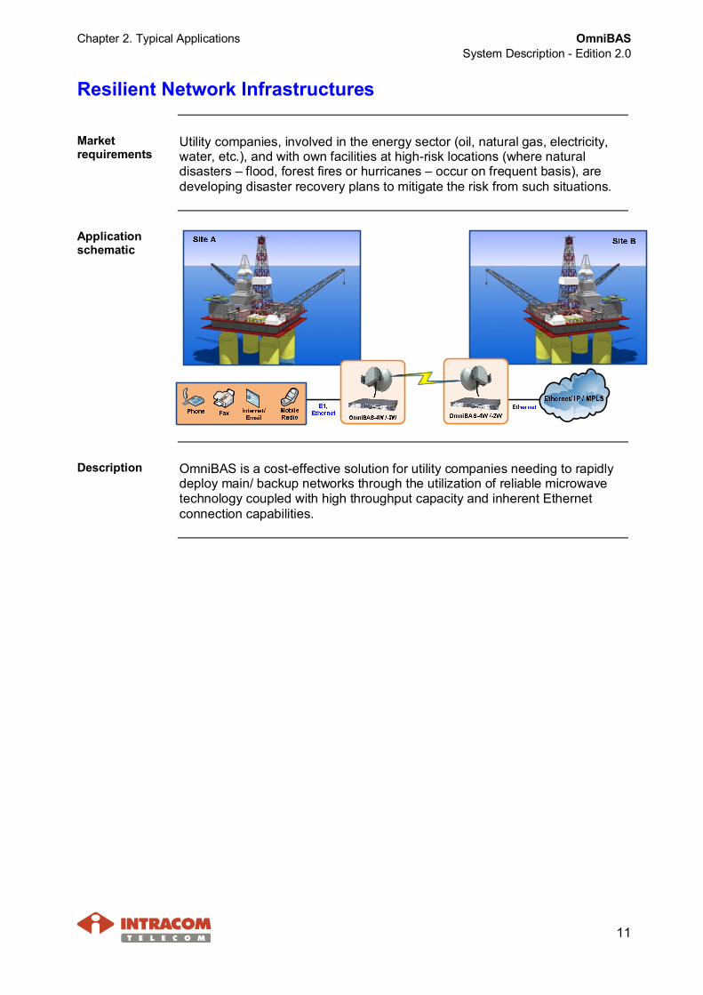
Resilient Network Infrastructures
Marketrequirements
Utility companies, involved in the energy sector (oil, natural gas, electricity,water, etc.), and with own facilities at high-risk locations (where naturaldisasters – flood, forest fires or hurricanes – occur on frequent basis), aredeveloping disaster recovery plans to mitigate the risk from such situations.
Applicationschematic
Description OmniBAS is a cost-effective solution for utility companies needing to rapidlydeploy main/ backup networks through the utilization of reliable microwavetechnology coupled with high throughput capacity and inherent Ethernetconnection capabilities.

OmniBASSystem Description - Edition 2.0
Chapter 3. Typical OmniBAS Configurations
12
3 Typical OmniBAS Configurations
This chapter describes the following typical OmniBAS configurations:· Link Configuration· Nodal Configuration· Ring Configuration

Chapter 3. Typical OmniBAS Configurations OmniBASSystem Description - Edition 2.0
13
Link Configuration
Linkconfigurationschematics
A typical OmniBAS configuration example is the repeated PtP link where arepeater station is used for extending the effective range of the link.The following schematic shows how a single OmniBAS handles repeaterconfiguration, protected and unprotected.
Edge (1+1)OmniBAS-4W/ 2WEdge (1+1)
OmniBAS-4W/ 2W OmniBAS-4WRepeater (2+2)
OmniBAS-4W/ 2WEdge (1+0)
OmniBAS-4W/ 2WRepeater (2+0)Edge (1+0)
OmniBAS-4W/ 2W
Repeater Configuration - Unprotected
Repeater Configuration - Protected
ETH/ E1ETH/ E1
BackboneNetwork
CorporateAccess
ETH/ E1ETH/ E1
BackboneNetwork
CorporateAccess
Add
Drop
Add
Dro
p
Description Both repeater configurations (unprotected and protected) of the aboveexamples, depicts three OmniBAS systems that are used to transport legacyE1 and Ethernet traffic from a corporation toward the backbone network.In the unprotected repeated configuration, the two OmniBAS-4W/ 2Wsystems at the edges of the link are configured for 1+0 operation, while thethird OmniBAS-4W/ 2W system at the repeater station is configured for 2+0operation.In the protected repeated configuration, the two OmniBAS-4W/ 2W systemsat the edges of the link are configured for 1+1 protected operation, while thethird OmniBAS-4W system at the repeater station is configured for 2+2protected operation.

OmniBASSystem Description - Edition 2.0
Chapter 3. Typical OmniBAS Configurations
14
Nodal Configuration
Schematic oftypical nodalconfiguration
The following schematic shows a typical nodal configuration for mobile2G/ 3G/ LTE network:
Description In this example, three OmniBAS-4W/ 2W systems (at the edges of thenetwork) and one OmniBAS-4W system (at the nodal station) are used.The nodal OmniBAS aggregates TDM/ ATM/ Ethernet traffic from a BTS/NodeB/ eNodeB site, a PtMP access network and a large corporation, andforwards it toward the Ethernet and legacy networks.As the schematic shows, two edge OmniBAS systems are configured for 1+0unprotected operation and the third edge OmniBAS system is configured for1+1 protected operation. Thus, the nodal OmniBAS is configured for2 x (1+0) and 1+1 operation.At the nodal station, several indoor units can be stacked to serve highernodal requirements.

Chapter 3. Typical OmniBAS Configurations OmniBASSystem Description - Edition 2.0
15
Ring Configuration
Schematic oftypical ringconfiguration
The following schematic shows how the OmniBAS-4W/ 2W systemsimplement a native Ethernet protected ring, according to ITU-T G.8032:
Description With regard to protection capabilities, OmniBAS allows the implementation ofEthernet protected rings (as per ITU-T G.8032) assuring a protectionrecovery switching much lower than 50 ms.In the above example, each OmniBAS-4W/ 2W system is configured for 2+0protected operation, while one of them (the one shown at the right) is usedfor forwarding traffic toward the backbone network.
Featurescomplied withRec. ITU-TG.8032
· Protection and recovery switching within 50 ms· Efficient bandwidth utilization of ring traffic· Automatic reversion mechanism upon fault recovery· Frame duplication and reorder prevention mechanisms· Loop prevention mechanisms· Use of different timers (WTR timer, Hold-off timers) to avoid race conditions
and unnecessary switching operations

OmniBASSystem Description - Edition 2.0
Chapter 4. Description of OmniBAS Key Functions
16
4 Description of OmniBAS Key Functions
This chapter provides the description of the following OmniBAS key functions:· Ethernet Functionality· Adaptive Modulation & Coding
Chapter 4. Description of OmniBAS Key Functions OmniBASSystem Description - Edition 2.0
17
4.1 Ethernet Functionality
This section presents the Layer 2 Bridging Modes supported by theOmniBAS system and then provides the following typical scenarios:· Mobile Backhaul (C-VLAN Mode)· Mobile & Corporate Backhaul
Layer 2 Bridging Modes
Layer 2bridging modes
OmniBAS supports the following L2 bridging modes:· C-VLAN· S-VLAN transparent· S-VLAN provider· S-VLAN transparent & provider
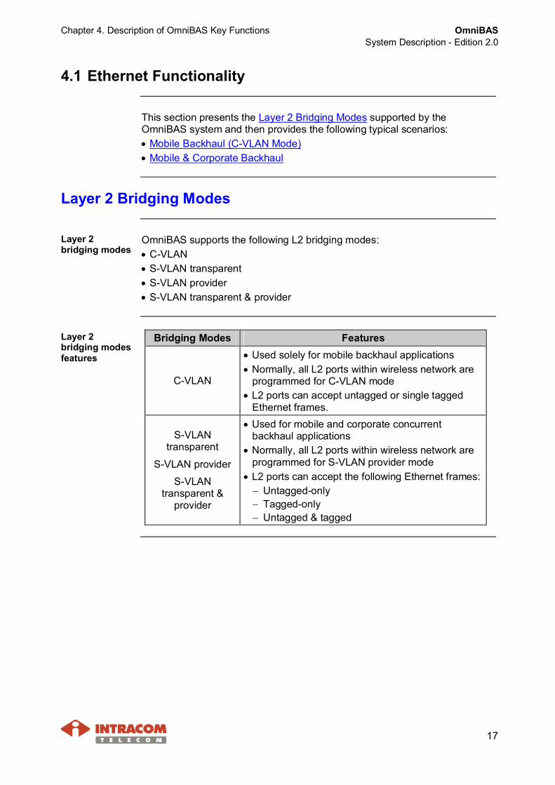
Layer 2bridging modesfeatures
Bridging Modes Features
C-VLAN
· Used solely for mobile backhaul applications· Normally, all L2 ports within wireless network are
programmed for C-VLAN mode· L2 ports can accept untagged or single tagged
Ethernet frames.
S-VLANtransparent
S-VLAN provider
S-VLANtransparent &
provider
· Used for mobile and corporate concurrentbackhaul applications
· Normally, all L2 ports within wireless network areprogrammed for S-VLAN provider mode
· L2 ports can accept the following Ethernet frames:- Untagged-only- Tagged-only- Untagged & tagged

OmniBASSystem Description - Edition 2.0
Chapter 4. Description of OmniBAS Key Functions
18
Mobile Backhaul (C-VLAN Mode)
Introduction The following network schematic depicts a typical wireless network where amobile operator, with E1 and Ethernet interfaces, needs to backhaul traffictoward the RNC. The required interworking functionality is provided by theOmniBAS system.
Schematic
Description Ethernet frames from all the BSs are forwarded to an Ethernet Switch, whichadds/ strips an S-tag for each individual C-VLAN.The Metro Ethernet Network (MEN) can be any of the following:· IEEE 802.1ad (QinQ)· PBB-TE· MPLS – in this case an appropriate MPLS router is used for mapping
C-VLANs to LSPsA single VLAN id opens a tunnel through the MEN toward the RNC. OnlyC-VLAN tagged Ethernet frames are forwarded.
Continued on next page

Chapter 4. Description of OmniBAS Key Functions OmniBASSystem Description - Edition 2.0
19
Mobile Backhaul (C-VLAN Mode), Continued
Description(continued)
The OmniBAS’s GbE ports (facing the access network) operate in C-VLANmode and L2 ports are programmed to accept tagged-only Ethernet frames.Also, the OmniBAS’s wireless ports operate in C-VLAN mode and L2 portsare programmed to accept tagged-only Ethernet frames for preventingundesired traffic from being forwarded.
Mobile & Corporate Backhaul
Introduction The following network schematic depicts a typical wireless network whereOmniBAS systems provide traffic backhaul services to mobile operators and tocorporate customers simultaneously.
Schematic
Bridge
NodeB #2(C-VLAN = 2)
Bridge Bridge
NodeB #1(C-VLAN = 1)
Bridge
NodeB #3(C-VLAN = 4)
Bridge
S-VLAN = 100
S-VLANs = 100, 101, 103
Metro EthernetNetwork – MEN
(Q-in-Q)
RNC
C-VLANs = 1,2,4
S-VLAN = 101
S-VLAN = 103
Bridge
Business B #1VLAN Switch
(C-VLANs = 2,8,4)
S-VLAN = 103
S-VLAN = 102
S-VLAN = 104
S-VLANs = 102, 103, 104
S-VLANs = 100,101,102, 104
Bridge
Bridge Bridge
ProviderQ-in-Q Switch
ProviderQ-in-Q Switch
ProviderQ-in-QSwitch
S-VLAN transparent L2 port
S-VLAN provider L2 port
S-VLANs =100,101,102
S-VLANs = 104
C-VLANs = 2,8,4
Business A #1VLAN Switch
(C-VLANs = 2,8,16)
Business A #2VLAN Switch
(C-VLANs = 2,8,16)
Business B #2VLAN Switch
(C-VLANs = 2,8,4)
Continued on next page

OmniBASSystem Description - Edition 2.0
Chapter 4. Description of OmniBAS Key Functions
20
Mobile & Corporate Backhaul, Continued
Description Ethernet traffic from NodeB sites is forwarded toward the RNC site, whilecorporate Ethernet traffic – from business A and business B sites – isforwarded toward the respective remote corporate premises.OmniBAS nodes need to add the appropriate Service provider tags (S-tags).OmniBAS’s functionality at the UNIs is as follows:
Site Addition/ Stripping of S-tags
NodeB #1 OmniBAS at NodeB #1 site adds an S-tag=100 at ingressand strips the S-tag=100 at egress
NodeB #2 OmniBAS at NodeB #2 site adds an S-tag=101 at ingressand strips the S-tag=101 at egress
NodeB #3 OmniBAS at NodeB #3 site adds an S-tag=102 at ingressand strips the S-tag=102 at egress
Business A #1OmniBAS at Business A #1 site adds an S-tag=103 for thewhole user port (E-Line service) at ingress and strips theS-tag=103 at egress
Business A #2OmniBAS at Business A #2 site adds an S-tag=103 for thewhole user port (E-Line service) at ingress and strips theS-tag=103 at egress
Business B #1OmniBAS at Business B #1 site adds an S-tag=104 for thewhole user port (E-Line service) at ingress and strips theS-tag=104 at egress
Business B #2The VLAN Switch at Business B #2 site adds anS-tag=104 for the whole user port (E-Line service) atingress and strips the S-tag=104 at egress
The OmniBAS’s GbE ports (facing the access network) operate in S-VLANtransparent mode. The ingress filter can be programmed to accepttagged-only Ethernet frames.The Metro Ethernet Network (MEN) can be any of the following:· IEEE 802.1ad (QinQ)· PBB-TE· MPLS – in this case an appropriate MPLS router is used for mapping
C-VLANs to LSPsThe S-VLAN id is used for opening a tunnel toward the RNC and through theMEN. The OmniBAS’s L2 ports, which are attached to the MEN, areconfigured in S-VLAN provider mode.

Chapter 4. Description of OmniBAS Key Functions OmniBASSystem Description - Edition 2.0
21
4.2 Adaptive Modulation & Coding
Introduction In microwave PtP radio networks, the link performance as well as the serviceavailability is highly affected by the weather conditions. OmniBAS incorporatesa dynamic adaptive mechanism, which offers several significant benefits:· Ensuring maximum bandwidth under all weather conditions – guaranteed
critical services all the time· Increasing capacity – excessive capacity can be exploited for value added
packet-based services with high availability· Increasing ARPU (in combination with the OmniBAS’s statistical multiplexing
capability)· Extending reach with lower availability
Description OmniBAS automatically adjust modulation – from 256QAM to QPSK and viceversa – to enable higher throughputs and better spectral efficiencies.Switchover to another modulation is carried out seamlessly without affectingthe link operation by any means.OmniBAS is designed to always operate in the highest possible modulation,according to link quality metrics. This way, the critical, real-time applicationsrun unaffected, independently of the weather conditions.During stormy weather, for instance, OmniBAS automatically reduces themodulation so that non real-time, data-based applications may be affected bythroughput degradation, but real-time, high-revenue applications (such asreal-time video and voice) will continue to run uninterrupted.Changing the modulation also varies the throughput proportionally. Forexample, 256QAM modulation can deliver four times the throughput of 4QAM(QPSK). The excessive bandwidth (other that that used for critical applications)can be allocated to non real-time applications, such as download services,which are less tolerant to system availability.
OmniBASSystem Description - Edition 2.0
Chapter 5. System Composition
22
5 System Composition
This chapter describes the equipment of the OmniBAS system that includes:· Main indoor equipment (OmniBAS-4W/ 2W)· Traffic aggregation units (OmniWAY-12G/ 2G) that constitute optional
indoor equipment· Outdoor equipment (ODU-CF units and antennas)
OmniBAS Indoor Equipment (OmniBAS-4W/ 2W)
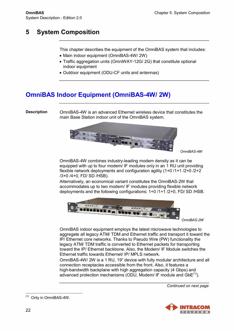
Description OmniBAS-4W is an advanced Ethernet wireless device that constitutes themain Base Station indoor unit of the OmniBAS system.
OmniBAS-4W
OmniBAS-4W combines industry-leading modem density as it can beequipped with up to four modem/ IF modules only in an 1 RU unit providingflexible network deployments and configuration agility (1+0 /1+1 /2+0 /2+2/3+0 /4+0, FD/ SD /HSB).Alternatively, an economical variant constitutes the OmniBAS-2W thataccommodates up to two modem/ IF modules providing flexible networkdeployments and the following configurations: 1+0 /1+1 /2+0, FD/ SD /HSB.
OmniBAS-2W
OmniBAS indoor equipment employs the latest microwave technologies toaggregate all legacy ATM/ TDM and Ethernet traffic and transport it toward theIP/ Ethernet core networks. Thanks to Pseudo Wire (PW) functionality thelegacy ATM/ TDM traffic is converted to Ethernet packets for transportingtoward the IP/ Ethernet backbone. Also, the Modem/ IF Module switches theEthernet traffic towards Ethernet/ IP/ MPLS network.OmniBAS-4W/ 2W is a 1 RU, 19“ device with fully modular architecture and allconnection receptacles accessible from the front. Also, it features ahigh-bandwidth backplane with high aggregation capacity (4 Gbps) andadvanced protection mechanisms (ODU, Modem/ IF module and GbE(1)).
Continued on next page
(1) Only in OmniBAS-4W.

Chapter 5. System Composition OmniBASSystem Description - Edition 2.0
23
OmniBAS Indoor Equipment (OmniBAS-4W/ 2W), Continued
OmniBAS-4Wmodules
This paragraph represents the modules that constitute the OmniBAS-4Wsubrack. The following schematic helps identifying the slots numbering of thesubrack.
Module AvailableSlots
Features
Modem/ IFModule 1, 2, 3, 4
· Native Ethernet unit· Throughput capability up to 400 Mbps· Fully adaptive modulation up to 256 QAM· TDM is carried in MEF8 PseudoWire· DAC, filtering, modulation and frequency up
conversion in the transmit path /ADC, demodulation and frequency downconversion in the receive path
· Multiplexing/ de-multiplexing between transmitand receive RF signals and service channelimplementation between indoor-outdoorequipment
Power Module 5, 6
· Converts –48 V dc voltage to the dc voltagelevels required by each component in the unit
· Second power module can be added forproviding power redundancy
Main ProcessorModule 7
· Ethernet switch capability· Aggregates all legacy TDM/ ATM and Ethernet
traffic· Supports TDM over PseudoWire· Internally redundant for core interfaces
E1 TributaryModule 8 · Up to 16 E1 add drop
Fan Module 9· Accommodates five fans to protect the housed
electronics against overheating· Fully hot swappable
Continued on next page

OmniBASSystem Description - Edition 2.0
Chapter 5. System Composition
24
OmniBAS Indoor Equipment (OmniBAS-4W/ 2W), Continued
OmniBAS-2Wmodules
OmniBAS-2W contains two slots for Modem/ IF modules and one slot for theMain Control Module. Below, the slots numbering and the modules description ofthe subrack are represented:
Module AvailableSlots
Features
Modem/ IFModule 1, 2
· Native Ethernet unit· Throughput capability up to 400 Mbps· Fully adaptive modulation up to 256 QAM· TDM is carried in MEF8 PseudoWire· DAC, filtering, modulation and frequency up
conversion in the transmit path /ADC, demodulation and frequency downconversion in the receive path
· Multiplexing/ de-multiplexing between transmitand receive RF signals and service channelimplementation between indoor-outdoorequipment
· Accommodates one fan to protect the housedelectronics against overheating
Main ControlModule 3
· Ethernet switch capability· Aggregates all legacy TDM/ ATM and Ethernet
traffic· Supports TDM over PseudoWire· Internally redundant for core interfaces· Up to 8 E1 add drop· Converts –48 V dc voltage to the dc voltage
levels required by each component in the unit· Fully hot swappable
Continued on next page
Chapter 5. System Composition OmniBASSystem Description - Edition 2.0
25
OmniBAS Indoor Equipment (OmniBAS-4W/ 2W), Continued
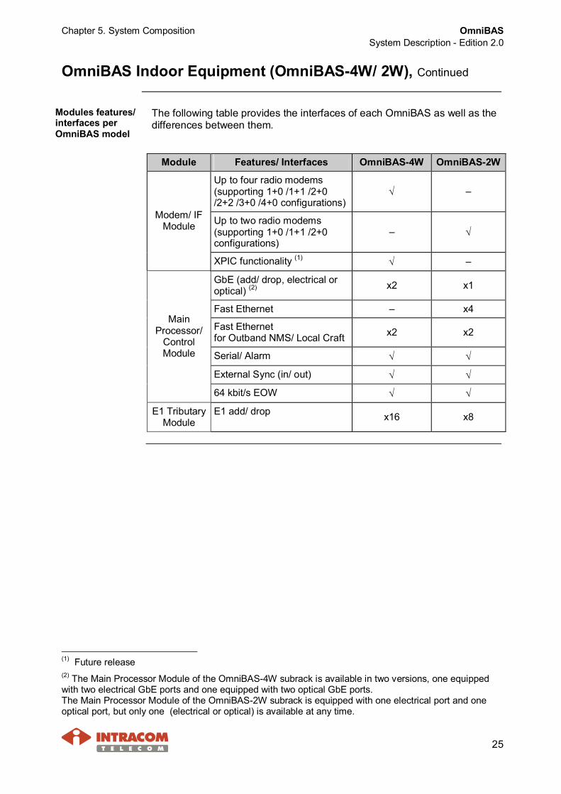
Modules features/interfaces perOmniBAS model
The following table provides the interfaces of each OmniBAS as well as thedifferences between them.
Module Features/ Interfaces OmniBAS-4W OmniBAS-2W
Up to four radio modems(supporting 1+0 /1+1 /2+0/2+2 /3+0 /4+0 configurations)
Ö –
Up to two radio modems(supporting 1+0 /1+1 /2+0configurations)
– Ö
Modem/ IFModule
XPIC functionality (1) Ö –
GbE (add/ drop, electrical oroptical) (2) x2 x1
Fast Ethernet – x4
Fast Ethernetfor Outband NMS/ Local Craft x2 x2
Serial/ Alarm Ö Ö
External Sync (in/ out) Ö Ö
MainProcessor/
ControlModule
64 kbit/s EOW Ö Ö
E1 TributaryModule
E1 add/ drop x16 x8
(1) Future release(2) The Main Processor Module of the OmniBAS-4W subrack is available in two versions, one equippedwith two electrical GbE ports and one equipped with two optical GbE ports.The Main Processor Module of the OmniBAS-2W subrack is equipped with one electrical port and oneoptical port, but only one (electrical or optical) is available at any time.

OmniBASSystem Description - Edition 2.0
Chapter 5. System Composition
26
OmniBAS Outdoor Equipment
Introduction The outdoor equipment of the OmniBAS system consists of outdoor radios(ODU-CF units) and integrated or standalone parabolic antennas.The following photo shows an ODU-CF together with a standalone parabolicantenna:
About ODU-CF OmniBAS system provides a complete family of ODU-CF units covering awide range of operating frequencies: 6 / 7 / 8 / 11 / 13 / 15 / 18 / 23 / 38 GHz.The ODU-CF incorporates the radio transceivers featuring capacity up to 400Mbps. It supports adaptive modulation schemes from QPSK to 256 QAM andchannel bandwidths from 7 MHz to 56 MHz. The capacity and modulationagility is achieved without the need of hardware change.The manufacturer performs the setting of the two ODU-CF units per linkaccording to the duplex spacing and the operation sub-band required by thecustomerODU-CF is environmentally hardened to guarantee quality operation underall conditions. The ODU-CF case meets IP55 requirements, is very rigid andis made of pressure die cast aluminum. It is suitable for mounting on a mast,through a mounting bracket included in the delivered package.ODU-CF can be mounted directly on an integrated parabolic antenna or itcan be connected with a standalone integrated antenna through a flexible,twistable waveguide.
Continued on next page

Chapter 5. System Composition OmniBASSystem Description - Edition 2.0
27
OmniBAS Outdoor Equipment, Continued
IF cabling The interconnection between an ODU-CF with a Modem/ IF Module of theOmniBAS-4W/ 2W is performed through a 50 Ω coaxial IF cable.The IF coaxial cable carries the following signals using frequency-divisionmultiplexing:· -48 V dc power to the ODU-CF· Bidirectional Service Channel (S.C.) data, enabling communication
between indoor and outdoor units· 140 MHz Rx IF signal· 350 MHz Tx IF signalODU-CF features female, N-Type receptacle to connect the IF coaxial cable.

OmniBASSystem Description - Edition 2.0
Chapter 5. System Composition
28
Traffic Aggregation Units (OmniWAY-12G/ 2G)
Description OmniWAY-12G (1) is a traffic aggregation unit used with the OmniBAS systemto provide higher-order SDH interfaces (STM-1 VC-12 and VC-4) for networknodes requiring such connectivity.OmniWAY-12G is a 3 RU switch aggregation unit that best fits highly densenodes requiring the highest level of protection.Incorporating a powerful Ethernet switch, OmniWAY-12G aggregatespacket-based traffic from multiple OmniBAS systems and forwards:· TDM/ ATM traffic toward the SDH network· Ethernet traffic toward the IP/MPLS networkThe fully redundant design of the OmniWAY-12G provides complete line andmodule protection for uninterruptible service delivery.The following photo shows the OmniWAY-12G subrack:
Alternatively, an economical variant constitutes the OmniWAY-2G that is acompact (1 RU, 19”) subrack used in case of low traffic aggregationrequirements. The following photo shows the OmniWAY-2G subrack:
Continued on next page
(1) Future release

Chapter 5. System Composition OmniBASSystem Description - Edition 2.0
29
Traffic Aggregation Units (OmniWAY-12G/ 2G), Continued
OmniWAY-12Gmodules
This paragraph represents the modules that constitute the OmniWAY-12Gsubrack. The following schematic helps identifying the slots numbering of thesubrack.
Module AvailableSlots
Description
LU-12 1, 2
· Multiple Services Interface Card providing the followinginterfaces:- Optical SDH interfaces:
2 x STM-1 (VC-4) in 1+1 and 2+0 configurations and4 x STM-1 (VC-12) in 2+2 configuration
- Sync IN/ OUT reference timing ports· Up to two LU-12 cards can be used. The second one
is added either to increase the STM-1 interfaces or toprovide card protection.
PU-12 3, 4
· Broadband Processing Unit providing the followinginterfaces:- 4 x GbE electrical Ethernet interfaces- 4 x GbE optical Ethernet interfaces- RS-232 serial interface and Fast Ethernet interface
for outband management· Up to two PU-12 cards can be used. The second one is
added for providing card protection.
Interfaceunit 5, 6
· Interface unit providing:- 12 x GbE traffic aggregation interfaces (optical or
electrical)- I/O port, for external alarms- 6 x Sync OUT reference timing ports- DC power input
· Up to two Interface units can be used. The second oneis added for providing protection.
Continued on next page

OmniBASSystem Description - Edition 2.0
Chapter 5. System Composition
30
Traffic Aggregation Units (OmniWAY-12G/ 2G), Continued
OmniWAY-2Gfront viewdescription
Below, the description of the OmniWAY-2G front view is provided. Allconnection receptacles of OmniWAY-2G are accessible from the front panel.
Item Interface1 Fan module accommodating fans for protecting the housed
electronics against overheating during operation.2 4 x GbE traffic aggregation interfaces (optical or electrical)3 2 x STM-1 / VC-4 (optical, 2+0 / 1+1)4 4 x STM-1 / VC-12 (optical, 2+0 / 2+2)5 Fast Ethernet, for outband management6 DC power input7 I/O port, for external alarms8 Sync IN/ OUT reference timing ports9 Serial RS-232, for local management
Continued on next page

Chapter 5. System Composition OmniBASSystem Description - Edition 2.0
31
Traffic Aggregation Units (OmniWAY-12G/ 2G), Continued
OmniBAS/OmniWAY-12Ginterconnection
As the following schematic shows, the OmniWAY-12G subrack:· Aggregates packet traffic from multiple OmniBAS systems (up to twelve)
through the GbE interfaces of the E1 Tributary Module· Regarding Ethernet traffic, this is processed by the internal switch of the
PU-12 card and forwarded toward the Ethernet/ IP/MPLS network throughthe GbE interfaces provided by the PU-12 card.
· Regarding legacy traffic, this is first converted internally to packets andthen forwarded toward the legacy SDH network through the STM-1/ VC-12interfaces provided by the LU-12 card.
For protection purposes all OmniWAY cabling with the distribution networksand OmniBAS-4W subracks is duplicated.
Cabling DescriptionA1 Uplink working path towards IP/ MPLS network (through GbE
interface)A2 Uplink protected path towards IP/ MPLS network (through GbE
interface)B1 Uplink working path towards legacy SDH network (through
STM-1/ VC-12 interface)B2 Uplink protected path towards legacy SDH network (through
STM-1/ VC-12 interface)C1…C12 Traffic aggregation working path (through GbE interface)D1…D12 Traffic aggregation protected path (through GbE interface)
Continued on next page

OmniBASSystem Description - Edition 2.0
Chapter 5. System Composition
32
Traffic Aggregation Units (OmniWAY-12G/ 2G), Continued
OmniBAS/OmniWAY-2Ginterconnection
The cabling example depicted in the following schematic shows anOmniWAY-2G subrack that is used for aggregating legacy traffic from fourOmniBAS-4W systems.The interconnection with the OmniWAY-2G is realized through the oneavailable GbE interface of each OmniBAS-4W system.The OmniWAY-2G subrack:· Aggregates packet traffic (from the OmniBAS-4W systems) through its
GbE interfaces.· Internally converts packets (associated with legacy traffic) to stream, which
is forwarded toward the SDH network through the STM-1 interfaces.The OmniBAS-4W systems switch and forward packets (associated withEthernet traffic) toward the IP/MPLS network through the second GbEinterface.
Cabling DescriptionA1 Uplink working path towards legacy SDH network (through
STM-1/ VC-12 interface of the OmniWAY-2G)A2 Uplink protected path towards legacy SDH network (through
STM-1/ VC-12 interface of the OmniWAY-2G)B1 … B4 Uplink GbE connections toward the IP/MPLS network for
Ethernet trafficC1 … C4 GbE interconnections for carrying packets (associated with
legacy-only traffic) toward the OmniWAY-2G

Chapter 6. Managing OmniBAS Networks OmniBASSystem Description - Edition 2.0
33
6 Managing OmniBAS Networks
The management of the OmniBAS system can be performed:· Locally, through the Local Craft Terminal application· Remotely, through the INTRACOM TELECOM’s Unified Management Suite
(uni½MS).Both management applications provide easy and efficient configuration andmonitoring of the OmniBAS system.
6.1 Local Craft Terminal
About LCT GUI The OmniBAS / OmniWAY Local Craft Terminal is a robust SNMP basedapplication designed to locally manage the OmniBAS and OmniWAY-2Gsystems.The Local Craft Terminal application features a user-friendly GUI (see below)displaying the OmniBAS / OmniWAY system elements in a tree structure (leftside pane). The parameters of each managed element are also displayed(right side pane) providing efficient monitoring and configuration of theOmniBAS and OmniWAY systems.
Continued on next page

OmniBASSystem Description - Edition 2.0
Chapter 6. Managing OmniBAS Networks
34
Local Craft Terminal, Continued
Managementfunctions
The following main functions are provided through Local Craft Terminal forthe management of the OmniBAS and OmniWAY systems:· Configuration Management:- Monitoring and configuration of OmniBAS elements (processor module,
modems, tributary module, fan trays, power supplies, interfaces, ODU-CFunits, etc.)
- Configuration and Monitoring of PtP links- Monitoring and configuration of OmniWAY elements (fan trays, power
supplies, interfaces, etc.)- Setting of the L2 bridging mode- Configuration and Monitoring of Ethernet and PW TDM traffic- Setting of Ethernet QoS (IEEE 802.1 P/Q priority in a VLAN packet
(Layer 2) and DSCP in an IP packet (Layer 3))- Setting of static MAC addresses- Configuration of systems synchronization- Re-configuration of systems in case of interruptions- Backup and restore of systems configuration
· Fault Management:- Monitoring of system active alarms and events- Active alarms and events storage (in log files)
· Test Management:- Loopback tests on the E1 lines of the tributary module- Loopback tests on the STM-1 / VC-12 ports
· Performance Management:- Monitoring of GbE performance- Monitoring of Ethernet traffic performance- Monitoring of PW TDM traffic performance- Monitoring of PW statistics- Monitoring of L2 ports performance

Chapter 6. Managing OmniBAS Networks OmniBASSystem Description - Edition 2.0
35
6.2 Unified Management Suite (uni½MS)
Overview
Introduction uniIMS Unified Management Suite constitutes INTRACOM TELECOM’ssolution for the rapid deployment, efficient supervision and consistentmanagement of telecommunications networks from a centralized location.uniIMS is a unified, high-scale and carrier-class Element, Network andService Management suite for all INTRACOM TELECOM products, wirelessand wireline, as well as for third party products through add-on drivers.
Highlights · Platform and vendor independent for low CapEx and OpEx – full Javaimplementation, not requiring third party operating system or data storagesoftware
· Multi-tier architecture for fitting small and large-scale networks – uniIMS iscomposed of multiple software server processes that are running into asingle hardware server, or distributed to multiple hardware servers forscalability and redundancy; one or more clients provide user interaction
· Open and expandable system for managing new network elements throughdrivers – new features can be added through add-on application modules
· Flexible and user configurable Graphical User Interface (GUI) withadvanced drag-n-drop capabilities
· Advanced security features – hardened operating system ensurescompliance to strict NOC security guidelines with fine-grained users, roles& privileges
· Northbound interfaces – various OSS/BSS integration protocols aresupported including Web services, SNMP, JAVA and JDBC
· Data-centric design for assured high system performance
Keycharacteristics
· 24x7 operation – no downtime during backup times· Real-time status presentation of the managed network· Collection of inventory-relevant metadata (serial numbers, firmware
releases, etc.) from the managed elements· Remote firmware upgrades (bulk or individual) and configuration backup· Advanced reporting capabilities; users can define their own reports with
SQL and add them in menus – the reports are interactive, i.e. users canperform actions from within the reports
· Detailed event logging regarding user / system / element actions· Service agnostic workflow engine (standard BPEL 2.0) supporting
convergent business logic for service provisioning and activation
Continued on next page

OmniBASSystem Description - Edition 2.0
Chapter 6. Managing OmniBAS Networks
36
Overview, Continued
Keycharacteristics(continued)
· Web services / SOAP implementation of SOA allowing the rapid integrationwith legacy systems
· Incorporated Enterprise Service Bus supporting unlimited number ofincoming service provisioning requests and thousands of simultaneousoutgoing connections

Chapter 6. Managing OmniBAS Networks OmniBASSystem Description - Edition 2.0
37
Layered Architecture
Introduction uniIMS is a client – server system built on a completely element-independentJava/ J2EE modern framework. uniIMS employs a truly modular softwarestructure design, which allows server processes to be distributed orduplicated, for practically supporting an unlimited number of managednetwork elements and system users.
Layeredarchitecture
uniIMS’s layered architecture is described below:· Element Mediation layer, which provides the communication with the
managed elements for applying management functions. Each element typehas its own driver; multiple drivers may run concurrently in the same uniIMSserver
· Domain Management layer, which implements FCPS (Fault - Configuration- Performance - Security) management functions on multiple element typesbelonging to a technology domain (wireless backhaul domain, WiMAXdomain, wireline access domain, etc.)
· Resource Management layer, which provides cross-domain managementcapabilities such as status management, report management, sub-networkconnection (SNC) management, etc.
· Service Management layer, which implements service provisioning andactivation functions, via a service agnostic workflow (BPEL) and a designenvironment, for realizing rapid service provisioning of GSM, CDMA, VoIP,xDSL, IPTV, IMS services
· Client layer, which consists of multiple clients running the Graphical UserInterface (GUI) concurrently; the clients enable authorized users to interactwith uniIMS
uniIM
S
Continued on next page

OmniBASSystem Description - Edition 2.0
Chapter 6. Managing OmniBAS Networks
38
Layered Architecture, Continued
ElementMediation layer
uniIMS’s Element Mediation layer consists of drivers, each corresponding toa managed element type.The drivers implement the communication with the managed elements forapplying management functions such as configuration changes, performancecounters collection, alarms (traps) collection, service provisioning, inventorycollection and others.Communication with the managed elements is based on various protocols,such as SNMP, HTTP, FTP, CLI, etc.The management connectivity between uniIMS and the managed elementscan be realized in two ways:· Outband: there exists a separate network for management communication
completely separate from the network that uniIMS is managing. Thisexternal management communication network must provide IP connectivitybetween the uniIMS server(s) and all managed network elements. Theadvantage of using an outband connection is that the managementcommunication is not dependent on the state of the managed network
· Inband: communication between uniIMS servers and managed networkelements is implemented through the managed network itself. Usinginband, maintenance of a separate management communication network isnot needed. The disadvantage is that management communication isdependent on the state of the managed network

Chapter 6. Managing OmniBAS Networks OmniBASSystem Description - Edition 2.0
39
About Graphical User Interface
Introduction uniIMS features a highly customizable, user-friendly and drag-n-drop-enabled GUI that suites specific user preferences. Users are able tocustomize the viewing space in their monitors and also apply filtering to thedisplayed data.
uni½MS GUIrepresentation
The main environment of the uniIMS is shown below:
At the left side pane, uniIMS GUI presents the network in a hierarchicalstructure displaying all the elements within the managed network in a tree-like manner.At the right side pane, uniIMS GUI incorporates flexible tabs for helpingusers manage the way they browse their system reports (e.g. Domains,Managed Elements, Physical Terminations, etc.)
Using uni½MSGUI
The user can create geographical and administration Domains to groupelements that are also included in the network hierarchy. Users can addmanaged elements, as well as sub-networks to Domains with simple drag-n-drop actions. Domains can be hierarchical (Domains into a Domain). Userscan easily change the network hierarchy through drag-n-drop. Actions can beperformed to both individual elements and to Domains.Multiple GUI instances can view the same piece of information, which isautomatically updated in case of changes in the network. uniIMS ensuresthat all the GUI clients’ views are consistent at all times.The GUI also incorporates flexible tabs (right side pane) for helping usersmanage the way they browse their system reports (e.g. Domains, ManagedElements, Physical Terminations, etc.).
Continued on next page

OmniBASSystem Description - Edition 2.0
Chapter 6. Managing OmniBAS Networks
40
About Graphical User Interface, Continued
Using uni(MSGUI (continued)
The tabs at right side pane also allow quick access to multiple reportsconcurrently, while the advanced report formatting and filtering capabilitiesincrease convenience during use.

Chapter 6. Managing OmniBAS Networks OmniBASSystem Description - Edition 2.0
41
Management Functions
Introduction This paragraph represents the management functions that the uniIMSprovides.
Faultmanagement
uniIMS’s Fault Management (FM) is responsible for the detection, isolationand resolution of problems in order to keep the supervised network runningat an optimum level, provide a measure of fault tolerance and minimizedowntime.The main functions of uni IMS’s fault management include:· Problem correlation· Problem visualization· Problem managementUsers can monitor alarms in real-time, while active and historical alarms arestored in the relational database, and are presented with additional viewsthat provide extensive filtering and exporting capabilities.
Configurationmanagement
The main tasks of uniIMS’s Configuration Management (CM) include thefollowing:· Automatic discovery and initial configuration of the network elements and of
their components· Monitoring of network configuration parameters· Network re-configuration (in case of interruptions)· Adaptation to planned operational modifications or user requirements· Configuration backup and restore
Performancemanagement
uniIMS’s Performance Management (PM) constitutes a means of measuringthe quality of several operating parameters. It ensures that the supervisednetwork is operating as expected and that the available network resourcesare efficiently allocated.Performance is determined by a specific period where appropriatemeasurements are taken on specific network elements (such as ports, trafficconnections, etc.).Within this period, measurement data is collected and stored in the databasefor later view or further analysis. When necessary, measurement data can beexported to files and presented in a list or graphical form.
Continued on next page

OmniBASSystem Description - Edition 2.0
Chapter 6. Managing OmniBAS Networks
42
Management Functions, Continued
Securitymanagement
uniIMS’s Security Management (SM) is responsible to protect both the entirenetwork and the managed elements against intentional or accidental abuse,unauthorized access and communication loss.Security management is also responsible to set constraints per managedelement according to the TMF MTNM specifications.uniIMS incorporates enhanced security features:· Security customizable per user (username / password – role – assigned
domains – allowed actions), according to predefined templates· Configurable security event logging, regarding user activities, based on
several logging criteria
Testmanagement
uniIMS’s Test Management (TEM) is responsible for localizing faults,dispatching corrective actions and preventively detecting possible troublespots within the managed network.The uniIMS’s testing capabilities, which include BER tests, setting ofloopbacks, etc., are provided by the add-on drivers of the managedelements.uniIMS manages test execution and progress, while test results arepresented in real-time.
Inventorymanagement
uniIMS’s Inventory Management (IVM) provides to users an overview of theinstalled equipment together with its location.uniIMS’s IM facilitates this task by automatically collecting hardware andsoftware information from the managed elements and storing them in adatabase for later view or export to other systems.
Softwaremanagement
The uniIMS’s software management capabilities enable the remote andcentralized software update of the managed elements for keeping network’soperational status up-to-date, or for adding new management features.

Chapter 6. Managing OmniBAS Networks OmniBASSystem Description - Edition 2.0
43
Add-on Applications
Network statusmanagement
uniIMS’s Status Management (SM) allows users monitor the operationalstatus of the network in real-time through an integrated graphical map-view.This map-view provides a view of the managed elements in theirgeographical location together with visual information of the elements’operational and fault status.uniIMS’s network status management also provides a graphicalrepresentation of the elements’ physical layout (including subracks, cards,etc.), which is interactive to enable fault and configuration managementcapabilities.The uniIMS’s network status management features include:· Vector background maps with representation of domains· Displaying real-time operational and alarm status information· Realistic representation of equipment with real-time alarm status· Zoom-in / zoom-out capabilities (resizing)· Drill-in / drill-out capabilities to display underneath entities (e.g. elements of
a domain, cards of an element, etc.)· Hide / show capabilities for nodes, cards, shelves, etc.· Showing links between the displayed elements
SNCmanagement
uniIMS’s Sub-Network Connection (SNC) Management allows users tocreate and manage sub-networks and their connections.Combined with uniIMS’s Status Management (SM), users can add sub-networks, topological links and create ATM, TDM and Ethernet connectionsthat can be monitored in a graphical circuit layout with real-time alarmindications and drill-in and drill-out capabilities.Sub-networks, topological links and sub-network connections are createdthrough intuitive wizards and can then be validated, activated / deactivatedand deleted.
Reportmanagement
uniIMS’s Report Management (REM) is an add-on application that allowsusers to create ad-hoc reports. These reports are listed in the left-side panefor quick navigation and are organized in folders to suit specific userpreferences. Reports are presented in tabular form showing element-relevantdata retrieved from the uniIMS database.Users are provided with a graphical presentation of the relational databasethat makes report design much more convenient. This way, users can viewthe database structure, run SQL queries and finally view the results.

OmniBASSystem Description - Edition 2.0
Chapter 6. Managing OmniBAS Networks
44
Service Provisioning
uniIMS provides convergent service provisioning capabilities addressing theneed for automated service provisioning across multi-vendor networks anddiverse IT environments.uniIMS’s ActionStreamerTM is an integrated service provisioning toolkit forthe mobile or fixed operator needing to rapidly introduce new services acrosstheir existing OSS / BSS and network infrastructure.ActionStreamerTM makes service provisioning an easy and intuitive taskthrough a graphical, BPEL standard (BPEL 2.0) workflow environment (seescreenshot below) that allows users to fully design, create, build, package,test and deploy new business processes, or modify existing ones.

Chapter 6. Managing OmniBAS Networks OmniBASSystem Description - Edition 2.0
45
Integration with 3rd Party Systems
uniIMS ensures rapid plug-and-play integration with external OSS or thirdparty management systems through its open architecture, which supportsscalability, extendibility and smooth integration with external systems.Off-the-self integration is provided through standardized northboundinterfaces, including Web Services, JAVA, JDBC and SNMP. Theseinterfaces fully cover the management functions (configuration, fault,performance, inventory and service provisioning), as required for integratedmanagement.uniIMS provides EMS to NMS integration (through Web Services), accordingto the Tele-management Forum’s MTNM standard.uniIMS is easily integrated with Order management systems to realizeservice provisioning via the open SOA architecture and Web Servicesinterface. Order activation is realized through integration with other third partyElement Management Systems (EMS), or directly with Network Elements.

OmniBASSystem Description - Edition 2.0
Chapter 7. Technical Specifications
46
7 Technical Specifications
This chapter provides the technical specifications of the OmniBAS system.The chapter includes the following sections:· 7.1 OmniBAS System Specifications· 7.2 Indoor Equipment Specifications· 7.3 ODU-CF Specifications· 7.4 Radio & Modem Performance
7.1 OmniBAS System Specifications
General Specification DescriptionOperating FrequencyBands
6 / 7 / 8 / 11 / 13 / 15 / 18 / 23 / 38 GHz
Modulation (adaptive)Schemes
4 / 8 / 16 / 32 / 64 / 128 / 256 QAM
Channel Size 7 / 14 / 28 / 56 MHzLink Modes · 1+0 / 2+0
· 1+1 (HSB/ SD/ FD)· 3+0 / 4+0 (OmniBAS-4W only)· 2+2 (HSB/ SD/ FD) (OmniBAS-4W only)
Operating DC Voltage -40 V to -60 V (-48 V typ.)OperatingTemperature
-5 ºC to 45 ºC
Relative Humidity 10% to 95%, non-condensing
Continued on next page

Chapter 7. Technical Specifications OmniBAS System Description - Edition 2.0
47
OmniBAS System Specifications, Continued
Networking Specification Description
TDM • ITU-T G.703 / G.736 / G.775 / G.823 • ITU-T G.783
Ethernet • IEEE 802.3u (100 Mbit/s electrical) • IEEE 802.3z (1000 Mbit/s optical) • IEEE 802.3ab (1000 Mbit/s electrical) • IEEE 802.1q (Virtual LAN) • IEEE 802.1p (QoS) • IEEE 802.1ad (Provider bridging)
Ethernet Synchronization
• Synchronous ETH • IEEE 1588v2 (1)
Ethernet Ring Protection
ITU-T G.8032
STM-1 (VC-12 / VC-4) ITU-T G.707 / G.781 / G.783 L2 Bridging Modes • C VLAN
• S-VLAN transparent • S-VLAN provider
QoS • per ETH port • per VLAN • per p-bit • DSCP
Standards Specification Description
EMC • ETSI EN 301 489-1 v1.6.1 (2002-09) • ETSI EN 301 489-4 v1.3.1 (2002-08)
Electrical Safety EN 60950-1:2001 Resistibility ITU K.20 Environmental • Operation:
ETSI EN 300 019-2-3 v2.1.2:2003, Class 3.2 • Transportation:
ETSI EN 300 019-2-2 v2.1.2:1999, Class 2.3 • Storage:
ETSI EN 300 019-2-1 v2.1.2:2000, Class 1.1 Radio ETSI EN 302 217-2-2
(1) Future release

OmniBASSystem Description - Edition 2.0
Chapter 7. Technical Specifications
48
7.2 Indoor Equipment Specifications
This paragraph provides the technical specifications of the following units:· OmniBAS-4W/ 2W· OmniWAY-12G· OmniWAY-2G
OmniBAS-4W/ 2W
Technicalspecifications
Specification OmniBAS-4W OmniBAS-2WMax. Bitrate (gross)(Mbit/s) 1600 800
Operating DC Voltage (V) -40 to -60 (-48 typ.)Max. PowerConsumption (W) (*)
87(for 4+0 configuration
without XPIC)
46(for 2+0 configuration)
Dimensions (mm) 45 (1U) x 437 x 284.7 45 (1U) x 407 x 240Weight (kg) 8.4 8Operating Temperature -5 ºC to 45 ºCHumidity(at 30 ºC) 10% to 95%, non-condensing
Interfaces Interface OmniBAS-4W OmniBAS-2WGbE (optical or electrical) 2 1E1 16 8Fast Ethernet – 4Fast Ethernet for OutbandNMS/ Local Craft 2 2
Sync IN / OUT 1 1Serial RS-232(I/O port for alarms) 1 1
EOW(Engineering Order Wire) 1 1
(*) Plus the power consumption of the interconnected ODU-CF

Chapter 7. Technical Specifications OmniBASSystem Description - Edition 2.0
49
OmniWAY-12G
Technicalspecifications
Specification DescriptionOperating DC Voltage (V) -40 to -60 (-48 typ.)Maximum PowerConsumption (W)
300
Dimensions (mm) 133.5 (3U) x 437 x 265Weight (kg) 13.5Operating Temperature -5 ºC to 45 ºCHumidity (at 30 ºC) 10% to 95%, non-condensing
Interfaces · 12 x GbE, electrical (traffic aggregation)· 8 x GbE (four electrical & four optical)· 4 x STM-1 / VC-12 (optical, 2+0 / 2+2)(*)
· 2 x STM-1 / VC-4 (optical, 2+0 / 1+1) (*)
· Fast Ethernet (outband management)· External I/O· 12 x Sync OUT & 1 Sync IN
OmniWAY-2G
Technicalspecifications
Specification DescriptionOperating DC Voltage (V) -40 to -60 (-48 typ.)Maximum PowerConsumption (W)
80
Dimensions (mm) 45 (1U) x 437 x 245Weight (kg) 6.5Operating Temperature -5 ºC to 45 ºCHumidity (at 30 ºC) 10% to 95%, non-condensing
Interfaces · 4 x GbE, optical or electrical (traffic aggregation)· 4 x STM-1 / VC-12 (optical, 2+0 / 2+2)· 2 x STM-1 / VC-4 (optical, 2+0 / 1+1)· Fast Ethernet (outband management)· Serial RS-232· External I/O· Sync IN / OUT
(*) Interfaces are also protected at card-level.

OmniBAS System Description - Edition 2.0
Chapter 7. Technical Specifications
50
7.3 ODU-CF Specifications
This section provides the technical specifications of the ODU-CF units (General Specifications and Specifications per ODU-CF Model).
General Specifications
Electrical Specification Description
Output Power Accuracy (max.)
• ± 1.5 dB (+25 °C) • ± 2 dB (-33 °C to +55 °C)
RSSI (RSL) Accuracy (typ.)
• ± 2 dB (+25 °C) • ± 3 dB (-33 °C to +55 °C)
Max. Rx Level (No Damage)
10 dBm
Frequency Stability (max.)
± 7 ppm
Frequency Resolution
250 kHz
Input Voltage (*) -48 V (-40 V to –60 V) Safety EN 60950 EMC ETSI EN 301489-1, ETSI EN 301489-4 RoHS 2002/ 95/ EC
Environmental Specification Description
Operating Temperature
-33 °C to +55 °C (ETSI EN 300 019-2-4 V2.1.2, Class 4.1) / Operational at -50 °C
Transportation & Storage Temperature
-40 °C to +70 °C (ETSI EN 300 019-2-2 V2.1.2, Class 2.3)
Relative Humidity (at 30 ºC)
90% to 100% (condensation), 93% (steady state) (ETSI EN 300 019-2-4 V2.1.2, Class 4.1)
Mechanical ODU-CF
Specification 6 GHz 7/ 8 GHz 11/ 13 GHz 15 GHz 18/ 23 GHz 38 GHz
Dimensions (H x W x D) (mm) 250 x 247 x 106 237 x 247 x 89
Weight (kg) < 6 < 4 Input Flange UBR70 UBR84 UBR120 UBR140 UBR220 UBR320
(*) The ODU-CF is power supplied from the OmniBAS-4W/ 2W through the IF coaxial cable.

Chapter 7. Technical Specifications OmniBASSystem Description - Edition 2.0
51
Specifications per ODU-CF Model
6 GHz Band DescriptionSpecification 256
QAM128
QAM64
QAM32
QAM16
QAM8
PSK4
QAMFrequency Band 5.9 GHz to 7.1 GHzRF ChannelArrangement ITU-R F.383/ 384
Tx/ Rx Spacing(Duplex Spacing) 252 / 240 / 340 MHz
Power Consumption 34 W (Typ.)Radio Perform.ETSI standard ETSI EN 302 217-2-2
Tx Output Power(upper) (dBm) 21 23 24 26 27 28 29
Tx Output Power(lower) (dBm) 9
ATPCRange (dB) 12 14 15 17 18 19 20
Rx Overload atBER 10-6 (dBm, typ.) -18 -17 -17 -15 -14 -13 -11
7 GHz Band DescriptionSpecification 256
QAM128
QAM64
QAM32
QAM16
QAM8
PSK4
QAMFrequency Band 7.1 GHz to 7.9 GHzRF ChannelArrangement ITU-R F.385-8
Tx/ Rx Spacing(Duplex Spacing) 154 / 161 / 168 / 245 MHz
Power Consumption 34 W (Typ.)Radio Perform.ETSI standard ETSI EN 302 217-2-2
Tx Output Power(upper) (dBm) 20 22 23 25 26 27 28
Tx Output Power(lower) (dBm) 9
ATPCRange (dB) 11 13 14 16 17 18 19
Rx Overload atBER 10-6 (dBm, typ.) -18 -17 -17 -15 -14 -13 -11
Continued on next page

OmniBASSystem Description - Edition 2.0
Chapter 7. Technical Specifications
52
Specifications per ODU-CF Model, Continued
8 GHz Band DescriptionSpecification 256
QAM128
QAM64
QAM32
QAM16
QAM8
PSK4
QAMFrequency Band 7.7 GHz to 8.5 GHzRF ChannelArrangement ITU-R F.386-6
Tx/ Rx Spacing(Duplex Spacing) 119 / 126 / 266 MHz
Power Consumption 34 W (Typ.)Radio Perform.ETSI standard ETSI EN 302 217-2-2
Tx Output Power(upper) (dBm) 19 21 22 24 25 26 27
Tx Output Power(lower) (dBm) 9
ATPCRange (dB) 10 12 13 15 16 17 18
Rx Overload atBER 10-6 (dBm, typ.) -18 -17 -17 -15 -14 -13 -11
11 GHz Band DescriptionSpecification 256
QAM128
QAM64
QAM32
QAM16
QAM8
PSK4
QAMFrequency Band 10.7 GHz to 11.7 GHzRF ChannelArrangement ITU-R F.387-7
Tx/ Rx Spacing(Duplex Spacing) 490 / 530 MHz
Power Consumption 26 W (Typ.)Radio Perform.ETSI standard ETSI EN 302 217-2-2
Tx Output Power(upper) (dBm) 19 21 22 24 25 26 27
Tx Output Power(lower) (dBm) 7
ATPCRange (dB) 12 14 15 17 18 19 20
Rx Overload atBER 10-6 (dBm, typ.) -18 -17 -17 -15 -14 -13 -11
Continued on next page

Chapter 7. Technical Specifications OmniBASSystem Description - Edition 2.0
53
Specifications per ODU-CF Model, Continued
13 GHz Band DescriptionSpecification 256
QAM128
QAM64
QAM32
QAM16
QAM8
PSK4
QAMFrequency Band 12.75 GHz to 13.25 GHzRF ChannelArrangement ITU-R F.497-6
Tx/ Rx Spacing(Duplex Spacing) 266 MHz
Power Consumption 26 W (Typ.)Radio Perform.ETSI standard ETSI EN 302 217-2-2
Tx Output Power(upper) (dBm) 16 18 19 21 22 23 24
Tx Output Power(lower) (dBm) 7
ATPCRange (dB) 9 11 12 14 15 16 17
Rx Overload atBER 10-6 (dBm, typ.) -18 -17 -17 -15 -14 -13 -11
15 GHz Band DescriptionSpecification 256
QAM128
QAM64
QAM32
QAM16
QAM8
PSK4
QAMFrequency Band 14.5 GHz to 15.35 GHzRF ChannelArrangement ITU-R F.636-3
Tx/ Rx Spacing(Duplex Spacing) 420 / 490 / 728 MHz
Power Consumption 23 W (Typ.)Radio Perform.ETSI standard ETSI EN 302 217-2-2
Tx Output Power(upper) (dBm) 16 18 19 21 22 23 24
Tx Output Power(lower) (dBm) 7
ATPCRange (dB) 9 11 12 14 15 16 17
Rx Overload atBER 10-6 (dBm, typ.) -18 -17 -17 -15 -14 -13 -11
Continued on next page

OmniBASSystem Description - Edition 2.0
Chapter 7. Technical Specifications
54
Specifications per ODU-CF Model, Continued
18 GHz Band DescriptionSpecification 256
QAM128
QAM64
QAM32
QAM16
QAM8
PSK4
QAMFrequency Band 17.7 GHz to 19.7 GHzRF ChannelArrangement ITU-R F.595-8
Tx/ Rx Spacing(Duplex Spacing) 1008 / 1010 MHz
Power Consumption 23 W (Typ.)Radio Perform.ETSI standard ETSI EN 302 217-2-2
Tx Output Power(upper) (dBm) 16 18 19 21 22 23 24
Tx Output Power(lower) (dBm) 7
ATPCRange (dB) 9 11 12 14 15 16 17
Rx Overload atBER 10-6 (dBm, typ.) -18 -17 -17 -15 -14 -13 -11
23 GHz Band DescriptionSpecification 256
QAM128
QAM64
QAM32
QAM16
QAM8
PSK4
QAMFrequency Band 21.2 GHz to 23.6 GHzRF ChannelArrangement ITU-R F.637-3
Tx/ Rx Spacing(Duplex Spacing) 1008 / 1232 MHz
Power Consumption 23 W (Typ.)Radio Perform.ETSI standard ETSI EN 302 217-2-2
Tx Output Power(upper) (dBm) 15 17 18 20 21 22 23
Tx Output Power(lower) (dBm) 6
ATPCRange (dB) 9 11 12 14 15 16 17
Rx Overload atBER 10-6 (dBm, typ.) -18 -17 -17 -15 -14 -13 -11
Continued on next page

Chapter 7. Technical Specifications OmniBASSystem Description - Edition 2.0
55
Specifications per ODU-CF Model, Continued
38 GHz Band DescriptionSpecification 256
QAM128
QAM64
QAM32
QAM16
QAM8
PSK4
QAMFrequency Band 37.0 GHz to 39.5 GHzRF ChannelArrangement ITU-R F.749-2
Tx/ Rx Spacing(Duplex Spacing) 1260 MHz
Power Consumption 23 W (Typ.)Radio Perform.ETSI standard ETSI EN 302 217-2-2
Tx Output Power(upper) (dBm) 13 15 16 18 19 20 21
Tx Output Power(lower) (dBm) 6
ATPCRange (dB) 7 9 10 12 13 14 15
Rx Overload atBER 10-6 (dBm, typ.) -19 -18 -18 -16 -15 -14 -12
OmniBASSystem Description - Edition 2.0
Chapter 7. Technical Specifications
56
7.4 Radio & Modem Performance
Introduction This section provides the radio and modem performance of the OmniBASsystem, inclusive of:· Rx Thresholds· System Gain· Net Throughput· Link Ranges
Configurationscenarios forOmniBASperformance
The radio and modem performance provided in this section concerns thefollowing configuration scenarios of the OmniBAS system:· Max. Robustness Configuration· Optimized Robustness/ Capacity Configuration· Max. Capacity ConfigurationNext table describes the three different configuration scenarios of theOmniBAS system:
Continued on next page

Chapter 7. Technical Specifications OmniBASSystem Description - Edition 2.0
57
Radio & Modem Performance, Continued
Configuration scenarios for OmniBAS performance (continued)
OmniBAS System Configuration ScenariosMax. Robustness Optimized
Robustness /Capacity
Max. Capacity
Symbol Rate Min. Intermediate Max.
FEC overhead Max. Intermediate Min.
Cha
ract
eris
tics
Adaptive modulationswitching margins
Max. Intermediate Min.
Radio Conformance with thesteepest spectralmask using 0.25 rollofffactor.1 dB higher transmitpower than OptimizedRobustness/ Capacityconfiguration.
Conformance withspectral masks using0.15 rolloff factor.1 dB lower transmitpower than Max.Robustnessconfiguration
Same transmit poweras OptimizedRobustness/ Capacityconfiguration.
Sensitivity Max., due to thehighest FECoverhead).0.5 dB highersensitivity thanOptimizedRobustness/ Capacityconfiguration.
Normal, due to theintermediate FECoverhead.
Min., due to the lowestFEC overhead.0.5 dB lower sensitivitythan OptimizedRobustness/ Capacityconfiguration.
Effe
cts
Immunity in variablechannel conditions
Increased Normal Smaller
Maximum transmitpower applications(long haul, over-seapaths).Best for frequencycongestedapplications.
Normal capacityapplications.Suitable for frequencycongestedapplications.
Maximum capacityapplications.Not suitable forfrequency congestedapplications.
Maximum system gainapplications (long-haul, over-sea paths).
Normal system gainapplications (sort,medium-haul paths).
Normal system gainapplications (sort,medium -haul paths).
TypicalApplications
Maximum linkreliability applications.Best for fast and deepfading paths
Normal link reliabilityapplications.Suitable for fast anddeep fading paths.
Less demanding linkreliability applications.Not suitable for fastand deep fading paths.

OmniBASSystem Description - Edition 2.0
Chapter 7. Technical Specifications
58
Rx Thresholds
Introduction This paragraph provides the OmniBAS Rx Thresholds (at BER = 10-6 ) for thefollowing cases:
Case ModulationType
OmniBAS ConfigurationScenarios
FrequencyBands
Case #1 Fixed
Case #2 AdaptiveMax. Robustness
Configuration
Case #3 Fixed
Case #4 AdaptiveOptimized Robustness/Capacity Configuration
Case #5 Fixed
Case #6 AdaptiveMax. CapacityConfiguration
All availablefrequency
bands(6 / 7 / 8 /11 /13 /15 / 18 /23 / 38 GHz)
For the description of the OmniBAS configuration scenarios, see par.Configuration scenarios for OmniBAS performance, on page 56.
Continued on next page

Chapter 7. Technical Specifications OmniBASSystem Description - Edition 2.0
59
Rx Thresholds, Continued
Case #1 The following table provides the Rx Threshold values of an OmniBAS systemin case of Max. Robustness Configuration and Fixed Modulation:
Rx Threshold (dBm) at BER=10-6
for Max. Robustness Configuration & Fixed ModulationODU-CF
Modulation Ch. Size6 /7 /8 /11 /13 /15 GHz 18 / 23 GHz 38 GHz
56 MHz -68.8 -67.8 -66.328 MHz -71.8 -70.8 -69.314 MHz -74.8 -73.8 -72.3
256 QAM
7 MHz -77.8 -76.8 -75.356 MHz -71.1 -70.1 -68.628 MHz -74.1 -73.1 -71.614 MHz -77.1 -76.1 -74.6
128 QAM
7 MHz -80.1 -79.1 -77.656 MHz -73.8 -72.8 -71.328 MHz -76.8 -75.8 -74.314 MHz -79.8 -78.8 -77.3
64 QAM
7 MHz -82.8 -81.8 -80.356 MHz -76.2 -75.2 -73.728 MHz -79.2 -78.2 -76.714 MHz -82.2 -81.2 -79.7
32 QAM
7 MHz -85.2 -84.2 -82.756 MHz -79.7 -78.7 -77.228 MHz -82.7 -81.7 -80.214 MHz -85.7 -84.7 -83.2
16 QAM
7 MHz -88.7 -87.7 -86.256 MHz N/A N/A N/A28 MHz N/A N/A N/A14 MHz N/A N/A N/A
8 PSK
7 MHz N/A N/A N/A56 MHz -85.3 -84.3 -82.828 MHz -88.3 -87.3 -85.814 MHz -91.3 -90.3 -88.8
4 QAMLow FEC
7 MHz -94.3 -93.3 -91.856 MHz -87.6 -86.6 -85.128 MHz -90.6 -89.6 -88.114 MHz -93.6 -92.6 -91.1
4 QAMHigh FEC
7 MHz -96.6 -95.6 -94.1
Continued on next page
OmniBASSystem Description - Edition 2.0
Chapter 7. Technical Specifications
60
Rx Thresholds, Continued
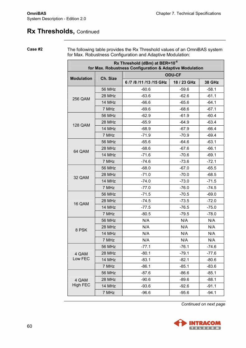
Case #2 The following table provides the Rx Threshold values of an OmniBAS systemfor Max. Robustness Configuration and Adaptive Modulation:
Rx Threshold (dBm) at BER=10-6
for Max. Robustness Configuration & Adaptive ModulationODU-CF
Modulation Ch. Size6 /7 /8 /11 /13 /15 GHz 18 / 23 GHz 38 GHz
56 MHz -60.6 -59.6 -58.128 MHz -63.6 -62.6 -61.114 MHz -66.6 -65.6 -64.1
256 QAM
7 MHz -69.6 -68.6 -67.156 MHz -62.9 -61.9 -60.428 MHz -65.9 -64.9 -63.414 MHz -68.9 -67.9 -66.4
128 QAM
7 MHz -71.9 -70.9 -69.456 MHz -65.6 -64.6 -63.128 MHz -68.6 -67.6 -66.114 MHz -71.6 -70.6 -69.1
64 QAM
7 MHz -74.6 -73.6 -72.156 MHz -68.0 -67.0 -65.528 MHz -71.0 -70.0 -68.514 MHz -74.0 -73.0 -71.5
32 QAM
7 MHz -77.0 -76.0 -74.556 MHz -71.5 -70.5 -69.028 MHz -74.5 -73.5 -72.014 MHz -77.5 -76.5 -75.0
16 QAM
7 MHz -80.5 -79.5 -78.056 MHz N/A N/A N/A28 MHz N/A N/A N/A14 MHz N/A N/A N/A
8 PSK
7 MHz N/A N/A N/A56 MHz -77.1 -76.1 -74.628 MHz -80.1 -79.1 -77.614 MHz -83.1 -82.1 -80.6
4 QAMLow FEC
7 MHz -86.1 -85.1 -83.656 MHz -87.6 -86.6 -85.128 MHz -90.6 -89.6 -88.114 MHz -93.6 -92.6 -91.1
4 QAMHigh FEC
7 MHz -96.6 -95.6 -94.1
Continued on next page

Chapter 7. Technical Specifications OmniBASSystem Description - Edition 2.0
61
Rx Thresholds, Continued
Case #3 The following table provides the Rx Threshold values of an OmniBAS systemfor Optimized Robustness/ Capacity Configuration and Fixed Modulation:
Rx Threshold (dBm) at BER=10-6
for Optimized Robustness/ Capacity Configuration & Fixed ModulationODU-CF
Modulation Ch. Size6 /7 /8 /11 /13 /15 GHz 18 / 23 GHz 38 GHz
56 MHz -67.4 -66.4 -64.928 MHz -70.2 -69.2 -67.714 MHz -73.3 -72.3 -70.8
256 QAM
7 MHz -76.3 -75.3 -73.856 MHz -69.9 -68.9 -67.428 MHz -72.7 -71.7 -70.214 MHz -75.8 -74.8 -73.3
128 QAM
7 MHz -78.8 -77.8 -76.356 MHz -72.5 -71.5 -70.028 MHz -75.3 -74.3 -72.814 MHz -78.4 -77.4 -75.9
64 QAM
7 MHz -81.4 -80.4 -78.956 MHz -75.0 -74.0 -72.528 MHz -77.8 -76.8 -75.314 MHz -80.9 -79.9 -78.4
32 QAM
7 MHz -83.9 -82.9 -81.456 MHz -78.4 -77.4 -75.928 MHz -81.2 -80.2 -78.714 MHz -84.3 -83.3 -81.8
16 QAM
7 MHz -87.3 -86.3 -84.856 MHz -81.3 -80.3 -78.828 MHz -84.1 -83.1 -81.614 MHz -87.2 -86.2 -84.7
8 PSK
7 MHz -90.2 -89.2 -87.756 MHz -84.9 -83.9 -82.428 MHz -87.7 -86.7 -85.214 MHz -90.8 -89.8 -88.3
4 QAMLow FEC
7 MHz -93.8 -92.8 -91.356 MHz -87.3 -86.3 -84.828 MHz -90.1 -89.1 -87.614 MHz -93.2 -92.2 -90.7
4 QAMHigh FEC
7 MHz -96.2 -95.2 -93.7
Continued on next page

OmniBASSystem Description - Edition 2.0
Chapter 7. Technical Specifications
62
Rx Thresholds, Continued
Case #4 The following table provides the Rx Threshold values of an OmniBAS systemfor Optimized Robustness/ Capacity Configuration and Adaptive Modulation:
Rx Threshold (dBm) at BER=10-6
for Optimized Robustness/ Capacity Configuration & Adaptive ModulationODU-CF
Modulation Ch. Size6 /7 /8 /11 /13 /15 GHz 18 / 23 GHz 38 GHz
56 MHz -62.4 -61.4 -59.928 MHz -65.2 -64.2 -62.714 MHz -68.3 -67.3 -65.8
256 QAM
7 MHz -71.3 -70.3 -68.856 MHz -64.9 -63.9 -62.428 MHz -67.7 -66.7 -65.214 MHz -70.8 -69.8 -68.3
128 QAM
7 MHz -73.8 -72.8 -71.356 MHz -67.5 -66.5 -65.028 MHz -70.3 -69.3 -67.814 MHz -73.4 -72.4 -70.9
64 QAM
7 MHz -76.4 -75.4 -73.956 MHz -70.0 -69.0 -67.528 MHz -72.8 -71.8 -70.314 MHz -75.9 -74.9 -73.4
32 QAM
7 MHz -78.9 -77.9 -76.456 MHz -73.4 -72.4 -70.928 MHz -76.2 -75.2 -73.714 MHz -79.3 -78.3 -76.8
16 QAM
7 MHz -82.3 -81.3 -79.856 MHz -75.3 -74.3 -72.828 MHz -78.1 -77.1 -75.614 MHz -81.2 -80.2 -78.7
8 PSK
7 MHz -84.2 -83.2 -81.756 MHz -79.9 -78.9 -77.428 MHz -82.7 -81.7 -80.214 MHz -85.8 -84.8 -83.3
4 QAMLow FEC
7 MHz -88.8 -87.8 -86.356 MHz -87.3 -86.3 -84.828 MHz -90.1 -89.1 -87.614 MHz -93.2 -92.2 -90.7
4 QAMHigh FEC
7 MHz -96.2 -95.2 -93.7
Continued on next page

Chapter 7. Technical Specifications OmniBASSystem Description - Edition 2.0
63
Rx Thresholds, Continued
Case #5 The following table provides the Rx Threshold values of an OmniBAS systemfor Max. Capacity Configuration and Fixed Modulation:
Rx Threshold (dBm) at BER=10-6
for Max. Capacity Configuration & Fixed ModulationODU-CF
Modulation Ch. Size6 /7 /8 /11 /13 /15 GHz 18 / 23 GHz 38 GHz
56 MHz -65.2 -64.2 -62.728 MHz -67.8 -66.8 -65.314 MHz -70.8 -69.8 -68.3
256 QAM
7 MHz -73.9 -72.9 -71.456 MHz -67.2 -66.2 -64.728 MHz -69.8 -68.8 -67.314 MHz -72.8 -71.8 -70.3
128 QAM
7 MHz -75.9 -74.9 -73.456 MHz -70.1 -69.1 -67.628 MHz -72.7 -71.7 -70.214 MHz -75.7 -74.7 -73.2
64 QAM
7 MHz -78.8 -77.8 -76.356 MHz -73.2 -72.2 -70.728 MHz -75.8 -74.8 -73.314 MHz -78.8 -77.8 -76.3
32 QAM
7 MHz -81.9 -80.9 -79.456 MHz -76.0 -75.0 -73.528 MHz -78.6 -77.6 -76.114 MHz -81.6 -80.6 -79.1
16 QAM
7 MHz -84.7 -83.7 -82.256 MHz -80.7 -79.7 -78.228 MHz -83.3 -82.3 -80.814 MHz -86.3 -85.3 -83.8
8 PSK
7 MHz -89.4 -88.4 -86.956 MHz -83.8 -82.8 -81.328 MHz -86.4 -85.4 -83.914 MHz -89.4 -88.4 -86.9
4 QAMLow FEC
7 MHz -92.5 -91.5 -90.056 MHz -87.1 -86.1 -84.628 MHz -89.7 -88.7 -87.214 MHz -92.7 -91.7 -90.2
4 QAMHigh FEC
7 MHz -95.8 -94.8 -93.3
Continued on next page

OmniBASSystem Description - Edition 2.0
Chapter 7. Technical Specifications
64
Rx Thresholds, Continued
Case #6 The following table provides the Rx Threshold values of an OmniBAS systemfor Max. Capacity Configuration and Adaptive Modulation:
Rx Threshold (dBm) at BER=10-6
for Max. Capacity Configuration & Adaptive ModulationODU-CF
Modulation Ch. Size6 /7 /8 /11 /13 /15 GHz 18 / 23 GHz 38 GHz
56 MHz -62.0 -61.0 -59.528 MHz -64.6 -63.6 -62.114 MHz -67.6 -66.6 -65.1
256 QAM
7 MHz -70.6 -69.6 -68.156 MHz -64.0 -63.0 -61.528 MHz -66.6 -65.6 -64.114 MHz -69.6 -68.6 -67.1
128 QAM
7 MHz -72.6 -71.6 -70.156 MHz -66.9 -65.9 -64.428 MHz -69.5 -68.5 -67.014 MHz -72.5 -71.5 -70.0
64 QAM
7 MHz -75.5 -74.5 -73.056 MHz -70.0 -69.0 -67.528 MHz -72.6 -71.6 -70.114 MHz -75.6 -74.6 -73.1
32 QAM
7 MHz -78.6 -77.6 -76.156 MHz -72.8 -71.8 -70.328 MHz -75.4 -74.4 -72.914 MHz -78.4 -77.4 -75.9
16 QAM
7 MHz -81.4 -80.4 -78.956 MHz -76.5 -75.5 -74.028 MHz -79.1 -78.1 -76.614 MHz -82.1 -81.1 -79.6
8 PSK
7 MHz -85.1 -84.1 -82.656 MHz -80.6 -79.6 -78.128 MHz -83.2 -82.2 -80.714 MHz -86.2 -85.2 -83.7
4 QAMLow FEC
7 MHz -89.2 -88.2 -86.756 MHz -87.1 -86.1 -84.628 MHz -89.7 -88.7 -87.214 MHz -92.7 -91.7 -90.2
4 QAMHigh FEC
7 MHz -95.8 -94.8 -93.3
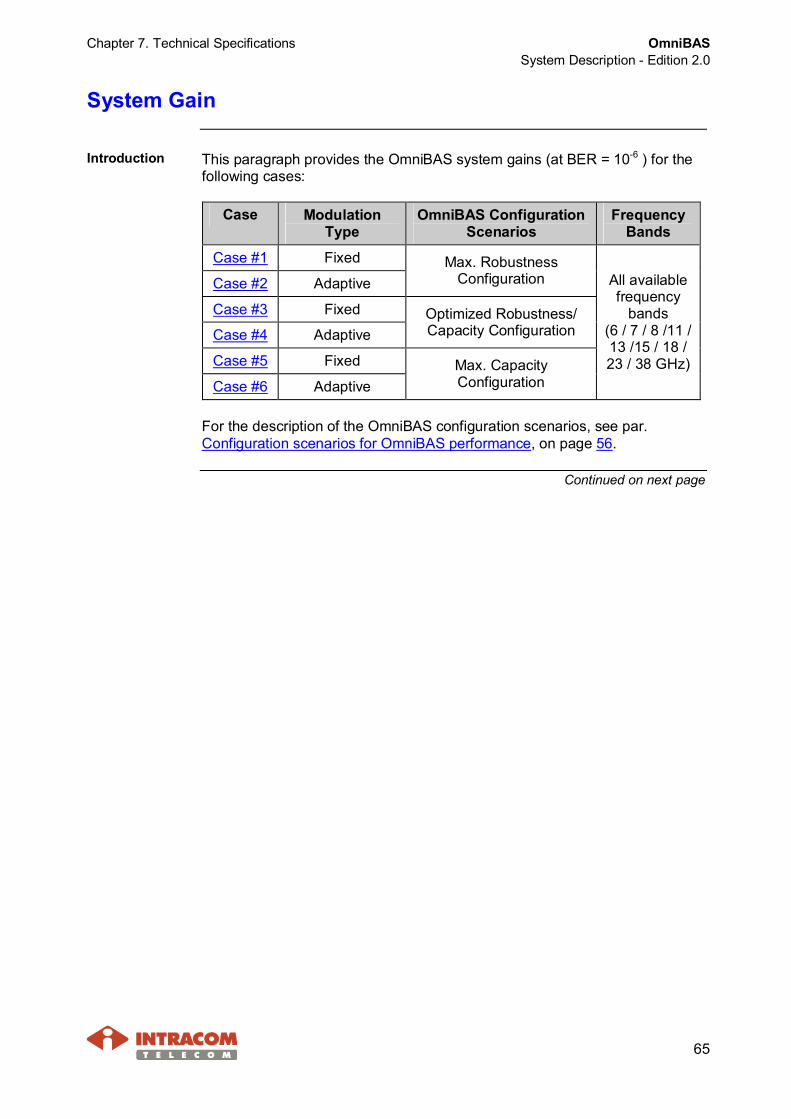
Chapter 7. Technical Specifications OmniBASSystem Description - Edition 2.0
65
System Gain
Introduction This paragraph provides the OmniBAS system gains (at BER = 10-6 ) for thefollowing cases:
Case ModulationType
OmniBAS ConfigurationScenarios
FrequencyBands
Case #1 Fixed
Case #2 AdaptiveMax. Robustness
Configuration
Case #3 Fixed
Case #4 AdaptiveOptimized Robustness/Capacity Configuration
Case #5 Fixed
Case #6 AdaptiveMax. CapacityConfiguration
All availablefrequency
bands(6 / 7 / 8 /11 /13 /15 / 18 /23 / 38 GHz)
For the description of the OmniBAS configuration scenarios, see par.Configuration scenarios for OmniBAS performance, on page 56.
Continued on next page

OmniBASSystem Description - Edition 2.0
Chapter 7. Technical Specifications
66
System Gain, Continued
Case #1 The following table provides the OmniBAS system gains in case of Max.Robustness configuration and Fixed Modulation:
System Gain (dB) at BER=10-6
for Max. Robustness Configuration & Fixed ModulationODU-CF
Modulation Ch.Size 6GHz
7GHz
8/ 11GHz
13/ 15GHz
18GHz
23GHz
38 GHz
56 MHz 89.8 88.8 87.8 84.8 83.8 82.8 79.328 MHz 92.8 91.8 90.8 87.8 86.8 85.8 82.314 MHz 95.8 94.8 93.8 90.8 89.8 88.8 85.3
256 QAM
7 MHz 98.8 97.8 96.8 93.8 92.8 91.8 88.356 MHz 94.1 93.1 92.1 89.1 88.1 87.1 83.628 MHz 97.1 96.1 95.1 92.1 91.1 90.1 86.614 MHz 100.1 99.1 98.1 95.1 94.1 93.1 89.6
128 QAM
7 MHz 103.1 102.1 101.1 98.1 97.1 96.1 92.656 MHz 97.8 96.8 95.8 92.8 91.8 90.8 87.328 MHz 100.8 99.8 98.8 95.8 94.8 93.8 90.314 MHz 103.8 102.8 101.8 98.8 97.8 96.8 93.3
64 QAM
7 MHz 106.8 105.8 104.8 101.8 100.8 99.8 96.356 MHz 102.2 101.2 100.2 97.2 96.2 95.2 91.728 MHz 105.2 104.2 103.2 100.2 99.2 98.2 94.714 MHz 108.2 107.2 106.2 103.2 102.2 101.2 97.7
32 QAM
7 MHz 111.2 110.2 109.2 106.2 105.2 104.2 100.756 MHz 106.7 105.7 104.7 101.7 100.7 99.7 96.228 MHz 109.7 108.7 107.7 104.7 103.7 102.7 99.214 MHz 112.7 111.7 110.7 107.7 106.7 105.7 102.2
16 QAM
7 MHz 115.7 114.7 113.7 110.7 109.7 108.7 105.256 MHz N/A N/A N/A N/A N/A N/A N/A28 MHz N/A N/A N/A N/A N/A N/A N/A14 MHz N/A N/A N/A N/A N/A N/A N/A
8 PSK
7 MHz N/A N/A N/A N/A N/A N/A N/A56 MHz 114.3 113.3 112.3 109.3 108.3 107.3 103.828 MHz 117.3 116.3 115.3 112.3 111.3 110.3 106.814 MHz 120.3 119.3 118.3 115.3 114.3 113.3 109.8
4 QAMLow FEC
7 MHz 123.3 122.3 121.3 118.3 117.3 116.3 112.856 MHz 116.6 115.6 114.6 111.6 110.6 109.6 106.128 MHz 119.6 118.6 117.6 114.6 113.6 112.6 109.114 MHz 122.6 121.6 120.6 117.6 116.6 115.6 112.1
4 QAMHigh FEC
7 MHz 125.6 124.6 123.6 120.6 119.6 118.6 115.1
Continued on next page

Chapter 7. Technical Specifications OmniBASSystem Description - Edition 2.0
67
System Gain, Continued
Case #2 The following table provides the OmniBAS system gains in case of Max.Robustness configuration and Adaptive Modulation:
System Gain (dB) at BER=10-6
for Max. Robustness Configuration & Adaptive ModulationODU-CF
Modulation Ch.Size 6GHz
7GHz
8/ 11GHz
13/ 15GHz
18GHz
23GHz
38GHz
56 MHz 81.6 80.6 79.6 76.6 75.6 74.6 71.128 MHz 84.6 83.6 82.6 79.6 78.6 77.6 74.114 MHz 87.6 86.6 85.6 82.6 81.6 80.6 77.1
256 QAM
7 MHz 90.6 89.6 88.6 85.6 84.6 83.6 80.156 MHz 85.9 84.9 83.9 80.9 79.9 78.9 75.428 MHz 88.9 87.9 86.9 83.9 82.9 81.9 78.414 MHz 91.9 90.9 89.9 86.9 85.9 84.9 81.4
128 QAM
7 MHz 94.9 93.9 92.9 89.9 88.9 87.9 84.456 MHz 89.6 88.6 87.6 84.6 83.6 82.6 79.128 MHz 92.6 91.6 90.6 87.6 86.6 85.6 82.114 MHz 95.6 94.6 93.6 90.6 89.6 88.6 85.1
64 QAM
7 MHz 98.6 97.6 96.6 93.6 92.6 91.6 88.156 MHz 94.0 93.0 92.0 89.0 88.0 87.0 83.528 MHz 97.0 96.0 95.0 92.0 91.0 90.0 86.514 MHz 100.0 99.0 98.0 95.0 94.0 93.0 89.5
32 QAM
7 MHz 103.0 102.0 101.0 98.0 97.0 96.0 92.556 MHz 98.5 97.5 96.5 93.5 92.5 91.5 88.028 MHz 101.5 100.5 99.5 96.5 95.5 94.5 91.014 MHz 104.5 103.5 102.5 99.5 98.5 97.5 94.0
16 QAM
7 MHz 107.5 106.5 105.5 102.5 101.5 100.5 97.056 MHz N/A N/A N/A N/A N/A N/A N/A28 MHz N/A N/A N/A N/A N/A N/A N/A14 MHz N/A N/A N/A N/A N/A N/A N/A
8 PSK
7 MHz N/A N/A N/A N/A N/A N/A N/A56 MHz 106.1 105.1 104.1 101.1 100.1 99.1 95.628 MHz 109.1 108.1 107.1 104.1 103.1 102.1 98.614 MHz 112.1 111.1 110.1 107.1 106.1 105.1 101.6
4 QAMLow FEC
7 MHz 115.1 114.1 113.1 110.1 109.1 108.1 104.656 MHz 116.6 115.6 114.6 111.6 110.6 109.6 106.128 MHz 119.6 118.6 117.6 114.6 113.6 112.6 109.114 MHz 122.6 121.6 120.6 117.6 116.6 115.6 112.1
4 QAMHigh FEC
7 MHz 125.6 124.6 123.6 120.6 119.6 118.6 115.1
Continued on next page

OmniBASSystem Description - Edition 2.0
Chapter 7. Technical Specifications
68
System Gain, Continued
Case #3 The following table provides the OmniBAS system gains in case of OptimizedRobustness/ Capacity configuration and Fixed Modulation:
System Gain (dB) at BER=10-6
for Optimized Robustness/ Capacity Configuration & Fixed ModulationODU-CF
Modulation Ch.Size 6GHz
7GHz
8/ 11GHz
13/ 15GHz
18GHz
23GHz
38GHz
56 MHz 88.4 87.4 86.4 83.4 82.4 81.4 77.928 MHz 91.2 90.2 89.2 86.2 85.2 84.2 80.714 MHz 94.3 93.3 92.3 89.3 88.3 87.3 83.8
256 QAM
7 MHz 97.3 96.3 95.3 92.3 91.3 90.3 86.856 MHz 92.9 91.9 90.9 87.9 86.9 85.9 82.428 MHz 95.7 94.7 93.7 90.7 89.7 88.7 85.214 MHz 98.8 97.8 96.8 93.8 92.8 91.8 88.3
128 QAM
7 MHz 101.8 100.8 99.8 96.8 95.8 94.8 91.356 MHz 96.5 95.5 94.5 91.5 90.5 89.5 86.028 MHz 99.3 98.3 97.3 94.3 93.3 92.3 88.814 MHz 102.4 101.4 100.4 97.4 96.4 95.4 91.9
64 QAM
7 MHz 105.4 104.4 103.4 100.4 99.4 98.4 94.956 MHz 101.0 100.0 99.0 96.0 95.0 94.0 90.528 MHz 103.8 102.8 101.8 98.8 97.8 96.8 93.314 MHz 106.9 105.9 104.9 101.9 100.9 99.9 96.4
32 QAM
7 MHz 109.9 108.9 107.9 104.9 103.9 102.9 99.456 MHz 105.4 104.4 103.4 100.4 99.4 98.4 94.928 MHz 108.2 107.2 106.2 103.2 102.2 101.2 97.714 MHz 111.3 110.3 109.3 106.3 105.3 104.3 100.8
16 QAM
7 MHz 114.3 113.3 112.3 109.3 108.3 107.3 103.856 MHz 109.3 108.3 107.3 104.3 103.3 102.3 98.828 MHz 112.1 111.1 110.1 107.1 106.1 105.1 101.614 MHz 115.2 114.2 113.2 110.2 109.2 108.2 104.7
8 PSK
7 MHz 118.2 117.2 116.2 113.2 112.2 111.2 107.756 MHz 113.9 112.9 111.9 108.9 107.9 106.9 103.428 MHz 116.7 115.7 114.7 111.7 110.7 109.7 106.214 MHz 119.8 118.8 117.8 114.8 113.8 112.8 109.3
4 QAMLow FEC
7 MHz 122.8 121.8 120.8 117.8 116.8 115.8 112.356 MHz 116.3 115.3 114.3 111.3 110.3 109.3 105.828 MHz 119.1 118.1 117.1 114.1 113.1 112.1 108.614 MHz 122.2 121.2 120.2 117.2 116.2 115.2 111.7
4 QAMHigh FEC
7 MHz 125.2 124.2 123.2 120.2 119.2 118.2 114.7
Continued on next page

Chapter 7. Technical Specifications OmniBASSystem Description - Edition 2.0
69
System Gain, Continued
Case #4 The following table provides the OmniBAS system gains in case of OptimizedRobustness/ Capacity configuration and Adaptive Modulation:
System Gain (dB) at BER=10-6
for Optimized Robustness/ Capacity Configuration & Adaptive ModulationODU-CF
Modulation Ch.Size 6GHz
7GHz
8/ 11GHz
13/ 15GHz
18GHz
23GHz
38GHz
56 MHz 83.4 82.4 81.4 78.4 77.4 76.4 72.928 MHz 86.2 85.2 84.2 81.2 80.2 79.2 75.714 MHz 89.3 88.3 87.3 84.3 83.3 82.3 78.8
256 QAM
7 MHz 92.3 91.3 90.3 87.3 86.3 85.3 81.856 MHz 87.9 86.9 85.9 82.9 81.9 80.9 77.428 MHz 90.7 89.7 88.7 85.7 84.7 83.7 80.214 MHz 93.8 92.8 91.8 88.8 87.8 86.8 83.3
128 QAM
7 MHz 96.8 95.8 94.8 91.8 90.8 89.8 86.356 MHz 91.5 90.5 89.5 86.5 85.5 84.5 81.028 MHz 94.3 93.3 92.3 89.3 88.3 87.3 83.814 MHz 97.4 96.4 95.4 92.4 91.4 90.4 86.9
64 QAM
7 MHz 100.4 99.4 98.4 95.4 94.4 93.4 89.956 MHz 96.0 95.0 94.0 91.0 90.0 89.0 85.528 MHz 98.8 97.8 96.8 93.8 92.8 91.8 88.314 MHz 101.9 100.9 99.9 96.9 95.9 94.9 91.4
32 QAM
7 MHz 104.9 103.9 102.9 99.9 98.9 97.9 94.456 MHz 100.4 99.4 98.4 95.4 94.4 93.4 89.928 MHz 103.2 102.2 101.2 98.2 97.2 96.2 92.714 MHz 106.3 105.3 104.3 101.3 100.3 99.3 95.8
16 QAM
7 MHz 109.3 108.3 107.3 104.3 103.3 102.3 98.856 MHz 103.3 102.3 101.3 98.3 97.3 96.3 92.828 MHz 106.1 105.1 104.1 101.1 100.1 99.1 95.614 MHz 109.2 108.2 107.2 104.2 103.2 102.2 98.7
8 PSK
7 MHz 112.2 111.2 110.2 107.2 106.2 105.2 101.756 MHz 108.9 107.9 106.9 103.9 102.9 101.9 98.428 MHz 111.7 110.7 109.7 106.7 105.7 104.7 101.214 MHz 114.8 113.8 112.8 109.8 108.8 107.8 104.3
4 QAMLow FEC
7 MHz 117.8 116.8 115.8 112.8 111.8 110.8 107.356 MHz 116.3 115.3 114.3 111.3 110.3 109.3 105.828 MHz 119.1 118.1 117.1 114.1 113.1 112.1 108.614 MHz 122.2 121.2 120.2 117.2 116.2 115.2 111.7
4 QAMHigh FEC
7 MHz 125.2 124.2 123.2 120.2 119.2 118.2 114.7
Continued on next page

OmniBASSystem Description - Edition 2.0
Chapter 7. Technical Specifications
70
System Gain, Continued
Case #5 The following table provides the OmniBAS system gains in case of Max.Capacity configuration and Fixed Modulation:
System Gain (dB) at BER=10-6
for Max. Capacity Configuration & Fixed ModulationODU-CF
Modulation Ch.Size 6GHz
7GHz
8/ 11GHz
13/ 15GHz
18GHz
23GHz
38GHz
56 MHz 86.2 85.2 84.2 81.2 80.2 79.2 75.728 MHz 88.8 87.8 86.8 83.8 82.8 81.8 78.314 MHz 91.8 90.8 89.8 86.8 85.8 84.8 81.3
256 QAM
7 MHz 94.9 93.9 92.9 89.9 88.9 87.9 84.456 MHz 90.2 89.2 88.2 85.2 84.2 83.2 79.728 MHz 92.8 91.8 90.8 87.8 86.8 85.8 82.314 MHz 95.8 94.8 93.8 90.8 89.8 88.8 85.3
128 QAM
7 MHz 98.9 97.9 96.9 93.9 92.9 91.9 88.456 MHz 94.1 93.1 92.1 89.1 88.1 87.1 83.628 MHz 96.7 95.7 94.7 91.7 90.7 89.7 86.214 MHz 99.7 98.7 97.7 94.7 93.7 92.7 89.2
64 QAM
7 MHz 102.8 101.8 100.8 97.8 96.8 95.8 92.356 MHz 99.2 98.2 97.2 94.2 93.2 92.2 88.728 MHz 101.8 100.8 99.8 96.8 95.8 94.8 91.314 MHz 104.8 103.8 102.8 99.8 98.8 97.8 94.3
32 QAM
7 MHz 107.9 106.9 105.9 102.9 101.9 100.9 97.456 MHz 103.0 102.0 101.0 98.0 97.0 96.0 92.528 MHz 105.6 104.6 103.6 100.6 99.6 98.6 95.114 MHz 108.6 107.6 106.6 103.6 102.6 101.6 98.1
16 QAM
7 MHz 111.7 110.7 109.7 106.7 105.7 104.7 101.256 MHz 108.7 107.7 106.7 103.7 102.7 101.7 98.228 MHz 111.3 110.3 109.3 106.3 105.3 104.3 100.814 MHz 114.3 113.3 112.3 109.3 108.3 107.3 103.8
8 PSK
7 MHz 117.4 116.4 115.4 112.4 111.4 110.4 106.956 MHz 112.8 111.8 110.8 107.8 106.8 105.8 102.328 MHz 115.4 114.4 113.4 110.4 109.4 108.4 104.914 MHz 118.4 117.4 116.4 113.4 112.4 111.4 107.9
4 QAMLow FEC
7 MHz 121.5 120.5 119.5 116.5 115.5 114.5 111.056 MHz 116.1 115.1 114.1 111.1 110.1 109.1 105.628 MHz 118.7 117.7 116.7 113.7 112.7 111.7 108.214 MHz 121.7 120.7 119.7 116.7 115.7 114.7 111.2
4 QAMHigh FEC
7 MHz 124.8 123.8 122.8 119.8 118.8 117.8 114.3
Continued on next page

Chapter 7. Technical Specifications OmniBASSystem Description - Edition 2.0
71
System Gain, Continued
Case #6 The following table provides the OmniBAS system gains in case of Max.Capacity configuration and Adaptive Modulation:
System Gain (dB) at BER=10-6
for Max. Capacity Configuration & Adaptive ModulationODU-CF
Modulation Ch.Size 6GHz
7GHz
8/ 11GHz
13/ 15GHz
18GHz
23GHz
38GHz
56 MHz 83.0 82.0 81.0 78.0 77.0 76.0 72.528 MHz 85.6 84.6 83.6 80.6 79.6 78.6 75.114 MHz 88.6 87.6 86.6 83.6 82.6 81.6 78.1
256 QAM
7 MHz 91.6 90.6 89.6 86.6 85.6 84.6 81.156 MHz 87.0 86.0 85.0 82.0 81.0 80.0 76.528 MHz 89.6 88.6 87.6 84.6 83.6 82.6 79.114 MHz 92.6 91.6 90.6 87.6 86.6 85.6 82.1
128 QAM
7 MHz 95.6 94.6 93.6 90.6 89.6 88.6 85.156 MHz 90.9 89.9 88.9 85.9 84.9 83.9 80.428 MHz 93.5 92.5 91.5 88.5 87.5 86.5 83.014 MHz 96.5 95.5 94.5 91.5 90.5 89.5 86.0
64 QAM
7 MHz 99.5 98.5 97.5 94.5 93.5 92.5 89.056 MHz 96.0 95.0 94.0 91.0 90.0 89.0 85.528 MHz 98.6 97.6 96.6 93.6 92.6 91.6 88.114 MHz 101.6 100.6 99.6 96.6 95.6 94.6 91.1
32 QAM
7 MHz 104.6 103.6 102.6 99.6 98.6 97.6 94.156 MHz 99.8 98.8 97.8 94.8 93.8 92.8 89.328 MHz 102.4 101.4 100.4 97.4 96.4 95.4 91.914 MHz 105.4 104.4 103.4 100.4 99.4 98.4 94.9
16 QAM
7 MHz 108.4 107.4 106.4 103.4 102.4 101.4 97.956 MHz 104.5 103.5 102.5 99.5 98.5 97.5 94.028 MHz 107.1 106.1 105.1 102.1 101.1 100.1 96.614 MHz 110.1 109.1 108.1 105.1 104.1 103.1 99.6
8 PSK
7 MHz 113.1 112.1 111.1 108.1 107.1 106.1 102.656 MHz 109.6 108.6 107.6 104.6 103.6 102.6 99.128 MHz 112.2 111.2 110.2 107.2 106.2 105.2 101.714 MHz 115.2 114.2 113.2 110.2 109.2 108.2 104.7
4 QAMLow FEC
7 MHz 118.2 117.2 116.2 113.2 112.2 111.2 107.756 MHz 116.1 115.1 114.1 111.1 110.1 109.1 105.628 MHz 118.7 117.7 116.7 113.7 112.7 111.7 108.214 MHz 121.7 120.7 119.7 116.7 115.7 114.7 111.2
4 QAMHigh FEC
7 MHz 124.8 123.8 122.8 119.8 118.8 117.8 114.3

OmniBASSystem Description - Edition 2.0
Chapter 7. Technical Specifications
72
Net Throughput
Introduction This paragraph provides the maximum throughput values of an OmniBASlink for the following configuration scenarios:· Max. Robustness Configuration· Optimized Robustness / Capacity Configuration· Max. Capacity ConfigurationFor the description of the OmniBAS configuration scenarios, see par.Configuration scenarios for OmniBAS performance, on page 56.
Max. throughputvalues for Max.Robustnessconfiguration
The following table provides the maximum throughput values for anOmniBAS link in case of Max. Robustness configuration:
Value per Channel Size (Mbit/s)Modulation56 MHz 28 MHz 14 MHz 7 MHz
256 QAM 293.57 146.28 72.23 35.21128 QAM 258.78 128.89 63.59 30.9064 QAM 221.19 110.10 54.22 26.2632 QAM 179.81 89.40 43.84 21.2616 QAM 143.90 71.45 34.99 16.748 PSK N/A N/A N/A N/A
4 QAM (Low FEC) 71.68 35.34 17.11 7.984 QAM (High FEC) 62.30 30.65 14.78 6.85
Max. throughputvalues forOptimizedRobustness /Capacityconfiguration
The following table provides the maximum throughput values for an OmniBASlink in case of Optimized Robustness/ Capacity configuration:
Value per Channel Size (Mbit/s)Modulation56 MHz 28 MHz 14 MHz 7 MHz
256 QAM 333.04 172.15 84.64 41.28128 QAM 293.80 151.81 74.59 36.3264 QAM 251.51 129.89 63.71 30.9432 QAM 204.51 105.53 51.61 24.9416 QAM 163.54 84.29 41.16 19.838 PSK 105.94 54.43 26.44 12.61
4 QAM (Low FEC) 81.41 41.72 20.16 9.484 QAM (High FEC) 67.70 34.61 16.64 7.75
Continued on next page

Chapter 7. Technical Specifications OmniBASSystem Description - Edition 2.0
73
Net Throughput, Continued
Max. throughputvalues for Max.Capacityconfiguration
The following table provides the maximum throughput values for an OmniBASlink in case of Max. Capacity configuration:
Value per Channel Size (Mbit/s)Modulation56 MHz 28 MHz 14 MHz 7 MHz
256 QAM 357.88 195.01 96.81 47.70128 QAM 315.61 171.93 85.28 42.0564 QAM 270.49 147.29 73.01 35.8732 QAM 219.85 119.62 59.46 28.8116 QAM 175.75 95.54 47.23 22.988 PSK 115.12 62.42 30.67 14.80
4 QAM (Low FEC) 87.46 47.31 23.16 11.034 QAM (High FEC) 69.76 37.65 18.31 8.64

OmniBASSystem Description - Edition 2.0
Chapter 7. Technical Specifications
74
Link Ranges
Introduction This paragraph provides link ranges values for the Athens, Moscow and NewDelhi in 7 / 18 / 38 GHz frequency bands.
Assumptions For the calculation of the provided link ranges, the following assumptions aretaken into account:
RegionsParameters
Athens Moscow New Delhi
Rain Intensity (R0.01) (*) 47.11 mm/hr 31.72 mm/hr 57.01 mm/hr
Geo-climatic Factor (**) 1.41E-03 1.97E-04 5.23E-04
Average Site Height (ASL) 250 m 200 m 225 m
Site Antenna Height Difference 50 m
Frequency bands 7 / 18 / 38 GHz
Channel Sizes 28 / 56 MHz
Modulation schemes 256 QAM to 4 QAM
Annual Availability(due to propagation) 99.995%
Modulation selection Adaptive
Link Mode 1+0
Antenna Used High Performance Parabolic Antenna(1.8 m diameter for 7 GHz band and
0.6 m diameter for 18 / 38 GHz band) (***)
Antenna Polarization Vertical
Prerequisites The ranges values mentioned hereinafter are indicative and cannot be usedfor dimensioning and design (special analysis per region and network isnecessary).The provided link ranges values are valid with the following prerequisites:· No intra-system or inter-system interference effects· No antenna off-axis loss effects· Clear LoS· No adverse propagation conditions (ducting, etc)· Professional installation
Continued on next page
(*) According to ITU-R Rec. P.837-5(**) According to ITU-R Rec. P.530-12(***) See also Appendix - Antenna Characteristics (page 77) for the technical specifications of the antennas.

Chapter 7. Technical Specifications OmniBASSystem Description - Edition 2.0
75
Link Ranges, Continued
Ranges at 7 GHz Modulation Link Ranges (km) at 7 GHzAthens Moscow New Delhi
56 MHz 28 MHz 56 MHz 28 MHz 56 MHz 28 MHz4 QAM 3/4 55.9 61.6 80.7 88.9 65.0 71.54 QAM 9/10 46.5 51.2 67.0 73.8 54.1 59.5
8 PSK 37.5 41.2 53.9 59.3 43.6 47.916 QAM 34.4 37.8 49.5 54.4 40.0 44.032 QAM 29.7 32.6 42.6 46.9 34.5 37.964 QAM 25.9 28.5 37.1 40.8 30.1 33.1128 QAM 22.5 24.7 32.1 35.3 26.1 28.6256 QAM 18.6 20.5 26.8 29.2 21.6 23.8
Ranges at 18 GHz Modulation Link Ranges (km) at 18 GHzAthens Moscow New Delhi
56 MHz 28 MHz 56 MHz 28 MHz 56 MHz 28 MHz4 QAM 3/4 15.4 16.7 22.1 24.2 14.4 15.74 QAM 9/10 13.1 14.2 18.6 20.4 12.3 13.4
8 PSK 10.8 11.8 15.1 16.6 10.1 11.016 QAM 10.0 10.9 13.9 15.3 9.4 10.232 QAM 8.7 9.5 12.0 13.2 8.1 8.964 QAM 7.6 8.4 10.4 11.5 7.1 7.8128 QAM 6.6 7.3 8.9 9.9 6.2 6.8256 QAM 5.4 6.0 7.2 8.0 5.1 5.6
Ranges at 38 GHz Modulation Link Ranges (km) at 38 GHzAthens Moscow New Delhi
56 MHz 28 MHz 56 MHz 28 MHz 56 MHz 28 MHz4 QAM 3/4 5.0 5.3 6.8 7.2 4.7 4.94 QAM 9/10 4.5 4.8 6.1 6.4 4.2 4.5
8 PSK 4.0 4.2 5.3 5.7 3.7 3.916 QAM 3.8 4.0 5.0 5.4 3.5 3.832 QAM 3.4 3.7 4.6 4.9 3.2 3.464 QAM 3.1 3.3 4.1 4.4 2.9 3.1128 QAM 2.8 3.0 3.7 4.0 2.6 2.8256 QAM 2.4 2.6 3.2 3.4 2.3 2.5

OmniBASSystem Description - Edition 2.0
Chapter 7. Technical Specifications
76
(Page intentionally left blank)

Appendix - Antenna Characteristics OmniBASSystem Description - Edition 2.0
77
Appendix - Antenna Characteristics
Introduction This appendix provides the characteristics of the following parabolicantennas that can be used for the OmniBAS system:· Antennas at 6 GHz Band· Antennas at 7 GHz & 8 GHz Bands· Antennas at 11 GHz Band· Antennas at 13 GHz Band· Antennas at 15 GHz Band· Antennas at 18 GHz Band· Antennas at 23 GHz Band· Antennas at 38 GHz Band
NOTE Other antennas, with different characteristics, are available uponcustomer request.
Antennaselectioncriteria
The antenna selection criteria mentioned in the tables of this Appendix arethe following:· Frequency - Frequencies over 10 GHz are subject to greater attenuation,
particularly in bad weather conditions and rain, since water and watervapors absorb the microwave radiation. Consequently, as the operationfrequency increases, the maximum distance between the transmitter andthe receiver decreases.
· Diameter -The greater the diameter of the antenna is, the greater the gainand the number of dBi. The higher the operating frequency is, the smallerthe diameter of the antenna can be to achieve the same gain. In otherwords, the microwave systems that operate at high frequencies have muchsmaller and consequently cheaper antennas.
· Mid Gain as the average value is the most representative.· F/B Ratio to control interferences at the rear side of the antenna.· Polarization (single or dual). The DP (Dual Polarization) antennas offer the
possibility of two signals with different polarization transmission from thesame antenna.
· XPD (Cross Polar Discrimination) to ensure low levels of disturbing cross-polarized signals and thus a safer reception. Typical XPD values rangefrom 30 dB for standard antennas to 40 dB for Ultra High Performanceantennas.
· Weight for the arrangement of the antenna mounting onto the pole/tower.· If the antenna is integrated (i.e. customized for direct ODU-CF attachment)
or not· Antenna vendor code number to be used as reference for the antenna
specifications. Do not use this code to place an order.

OmniBASSystem Description - Edition 2.0
Appendix - Antenna Characteristics
78
Antennas at 6 GHz Band
Introduction The following tables provide the antennas characteristics used at thefollowing frequency bands:· 5.925 GHz to 6.425 GHz (6 GHz (Lo))· 6.425 GHz to 7.125 GHz (6 GHz (Hi))
NOTE Other antennas, with different characteristics, are available uponcustomer request.
HighPerformance
Freq.Band
(6GHz)Diameter
ft (m)MidGain(dBi)
F/BRatio(dB)
Polari-zation
XPD(dB)
Weight(kg)
Inte-grated
AntennaVendor Code
Lo 4 (1.2) 34.5 56 DP 30 45 – RFS:DAX 4-59
Lo 6 (1.8) 38.7 64 DP 30 95 – RFS:DAX 6-59
Lo 8 (2.4) 41.3 67 DP 30 180 – RFS:DAX 8-59
Lo 10 (3.0) 43.2 69 DP 30 290 – RFS:DAX 10-59
Hi 4 (1.2) 35.3 58 DP 30 45 – RFS:DAX 4-65
Hi 6 (1.8) 39.7 64 DP 30 95 – RFS:DAX 6-65
Hi 8 (2.4) 42.2 68 DP 30 180 – RFS:DAX 8-65
Hi 10 (3.0) 43.9 70 DP 30 290 – RFS:DAX 10-65
Lo / Hi 4 (1.2) 35.7 62 SP 30 80 ÖKATHREIN:HP 12-059
S WB
Lo / Hi 6 (1.8) 39.3 68 SP 30 150 ÖKATHREIN:HP 18-059
S WB
Continued on next page

Appendix - Antenna Characteristics OmniBASSystem Description - Edition 2.0
79
Antennas at 6 GHz Band, Continued
Ultra HighPerformance& High XPD
Freq.Band
(6GHz)Diameter
ft (m)MidGain(dBi)
F/BRatio(dB)
Polari-zation
XPD(dB)
Weight(kg)
Inte-grated
AntennaVendor Code
Lo 6 (1.8) 38.7 69 DP 40 95 – RFS:UXA 6-59
Lo 8 (2.4) 41.3 71 DP 40 180 – RFS:UXA 8-59
Lo 10 (3.0) 43.2 74 DP 40 290 – RFS:UXA 10-59
Lo 12 (3.7) 44.8 76 DP 40 420 – RFS:UXA 12-59
Hi 6 (1.8) 39.7 69 DP 40 95 – RFS:UXA 6-65
Hi 8 (2.4) 42.2 71 DP 40 180 – RFS:UXA 8-65
Hi 10 (3.0) 43.9 74 DP 40 290 – RFS:UXA 10-65
Hi 12 (3.7) 45.6 76 DP 40 420 – RFS:UXA 12-65

OmniBASSystem Description - Edition 2.0
Appendix - Antenna Characteristics
80
Antennas at 7 GHz & 8 GHz Bands
Introduction The following tables provide the antennas characteristics used at 7.125 GHzto 8.500 GHz frequency band.
NOTE Other antennas, with different characteristics, are available uponcustomer request.
HighPerformance Diameter
ft (m)MidGain(dBi)
F/BRatio(dB)
Polari-zation
XPD(dB)
Weight(kg)
Inte-grated
Antenna VendorCode
2 (0.6) 31.3 52 SP 30 15 – RFS: DA2-W71or equivalent
4 (1.2) 37.3 62 SP 30 45 – RFS: DA4-W71or equivalent
6 (1.8) 40.8 66 SP 30 120 – RFS: DA6-W71or equivalent
8 (2.4) 43.3 68 SP 30 180 – RFS: DA8-W71or equivalent
10 (3.0) 45.3 70 SP 30 290 – RFS: DA10-W71or equivalent
Ultra HighPerformance Diameter
ft (m)MidGain(dBi)
F/BRatio(dB)
Polari-zation
XPD(dB)
Weight(kg)
Inte-grated
Antenna VendorCode
4 (1.2) 36.9 63 SP 30 39 ü RFS: SB4-W71or equivalent
4 (1.2) 37.0 63 SP 30 51 ü KATHREIN:THP12-071SWB
6 (1.8) 40.8 67 SP 30 95 ü RFS: SU6-W71or equivalent
6 (1.8) 40.6 67 DP 30 95 – RFS: SUX6-W71or equivalent
8 (2.4) 43.1 71 DP 30 180 – RFS: UDA8-W71or equivalent
10 (3.0) 45.1 73 DP 30 290 – RFS: UDA10-W71or equivalent

Appendix - Antenna Characteristics OmniBASSystem Description - Edition 2.0
81
Antennas at 11 GHz Band
Introduction The following tables provide the antennas characteristics used at 10.7 GHzto 11.7 GHz frequency band.
NOTE Other antennas, with different characteristics, are available uponcustomer request.
HighPerformance Diameter
ft (m)MidGain(dBi)
F/BRatio(dB)
Polari-zation
XPD(dB)
Weight(kg) Integrated Antenna Vendor
Code
2 (0.6) 35.1 60 SP 30 12 √ RFS:SB2-107
4 (1.2) 40.4 66 DP 32 35 – RFS:SUX 4-107
4 (1.2) 40.4 67 SP 30 35 √ RFS:SB4-107
6 (1.8) 43.9 70 DP 32 95 – RFS:SUX 6-107
6 (1.8) 44.0 70 SP 32 95 √ RFS:SU6-107
8 (2.4) 46.2 69 DP 30 180 – RFS:DAX 8-107
10 (3.0) 48.2 70 DP 30 290 – RFS:DAX 10-107
12 (3.7) 49.6 72 DP 30 420 – RFS:DAX 12-107
Ultra HighPerformance –High XPD
Diameterft (m)
MidGain(dBi)
F/BRatio(dB)
Polari-zation
XPD(dB)
Weight(kg) Integrated Antenna Vendor
Code
4 (1.2) 40.4 70 DP 40 40 – RFS:UXA 4-107
6 (1.8) 43.8 73 DP 40 95 – RFS:UXA 6-107
8 (2.4) 46.2 75 DP 40 180 – RFS:UXA 8-107
10 (3.0) 48.2 77 DP 40 290 – RFS:UXA 10-107
12 (3.7) 49.6 78 DP 40 420 – RFS:UXA 12-107

OmniBASSystem Description - Edition 2.0
Appendix - Antenna Characteristics
82
Antennas at 13 GHz Band
Introduction The following tables provide the antennas characteristics used at 12.70 GHzto 13.25 GHz frequency band.
NOTE Other antennas, with different characteristics, are available uponcustomer request.
HighPerformance Diameter
ft (m)MidGain(dBi)
F/BRatio(dB)
Polari-zation
XPD(dB)
Weight(kg) Integrated Antenna Vendor
Code
1 (0.3) 29.8 56 SP 30 4 ü RFS: SB1-127
2 (0.6) 35.2 61 SP 30 12 ü RFS: SB2-127
4 (1.2) 41.5 67 SP 30 35 ü RFS: SB4-127
6 (1.8) 45.3 66 SP 30 110 – RFS: SD6-127or equivalent
8 (2.4) 47.7 71 SP 30 180 – RFS: DA8-127or equivalent
10 (3.0) 49.5 71 SP 30 290 – RFS: DA10-127or equivalent
Ultra HighPerformance Diameter
ft (m)MidGain(dBi)
F/BRatio(dB)
Polari-zation
XPD(dB)
Weight(kg) Integrated Antenna Vendor
Code
2 (0.6) 35.3 65 DP 32 15 – RFS: SUX2-127or equivalent
3 (0.9) 38.8 64 DP 32 23 – RFS: SUX3-127or equivalent
4 (1.2) 41.5 67 DP 32 35 – RFS: SUX4-127or equivalent
6 (1.8) 45.1 72 SP 32 110 ü RFS: SU6-127
High XPD Diameterft (m)
MidGain(dBi)
F/BRatio(dB)
Polari-zation
XPD(dB)
Weight(kg) Integrated Antenna Vendor
Code
4 (1.2) 41.4 67 DP 40 40 – RFS: UXA4-127or equivalent
6 (1.8) 45.1 73 DP 40 110 – RFS: UXA6-127or equivalent
8 (2.4) 47.5 75 DP 40 180 – RFS: UXA8-127or equivalent

Appendix - Antenna Characteristics OmniBASSystem Description - Edition 2.0
83
Antennas at 15 GHz Band
Introduction The following tables provide the antennas characteristics used at 14.20 GHzto 15.35 GHz frequency band.
NOTE Other antennas, with different characteristics, are available uponcustomer request.
HighPerformance Diameter
ft (m)MidGain(dBi)
F/BRatio(dB)
Polari-zation
XPD(dB)
Weight(kg)
Inte-grated
Antenna VendorCode
1 (0.3) 31.1 53 SP 30 4 ü RFS: SB1-142
2 (0.6) 36.3 58 SP 30 12 ü RFS: SB2-142
2 (0.6) 36.4 65 DP 32 15 – RFS: SUX2-142Bor equivalent
2 (0.6) 36.8 (2) 65 SP 30 11 üKATHREIN:THP06-144S
3 (0.9) 39.9 64 DP 32 23 – RFS: SUX3-142or equivalent
4 (1.2) 42.4 70 DP 32 35 – RFS: SUX4-142or equivalent
4 (1.2) 42.5 70 SP 30 35 ü RFS: SB4-142
4 (1.2) 42.7 (2) 70 SP 30 51 üKATHREIN:THP12-144S
8 (2.4) 48.5 (2) 70 SP 30 180 – RFS: DA8-142or equivalent
10 (3.0) 50.5 (2) 72 SP 30 360 – RFS: DA10-142or equivalent
Continued on next page
(2) This antenna is used at 14.40 GHz to 15.35 GHz frequency band.

OmniBASSystem Description - Edition 2.0
Appendix - Antenna Characteristics
84
Antennas at 15 GHz Band, Continued
Ultra HighPerformance Diameter
ft (m)MidGain(dBi)
F/BRatio(dB)
Polari-zation
XPD(dB)
Weight(kg) Integrated Antenna Vendor
Code
2 (0.6) 36.4 62 DP 32 15 – RFS: SUX2-142or equivalent
3 (0.9) 39.9 64 DP 32 23 – RFS: SUX3-142or equivalent
4 (1.2) 42.4 70 DP 32 35 – RFS: SUX4-142or equivalent
4 (1.2) 42.5 70 SP 32 35 – RFS: SU4-142or equivalent
6 (1.8) 46.0 72 SP 32 110 ü RFS: SU6-142
6 (1.8) 46.0(3) 72 SP 32 110 – RFS: SU6-142or equivalent
High XPD Diameterft (m)
MidGain(dBi)
F/BRatio(dB)
Polari-zation
XPD(dB)
Weight(kg) Integrated Antenna Vendor
Code
2 (0.6) 36.5 64 DP 36 15 – RFS: UXA2-142or equivalent
4 (1.2) 42.5 70 DP 36 40 – RFS: UXA4-142or equivalent
6 (1.8) 46.0 75 DP 38 110 – RFS: UXA6-142or equivalent
(3) This antenna is used at 14.25 GHz to 15.35 GHz frequency band.

Appendix - Antenna Characteristics OmniBASSystem Description - Edition 2.0
85
Antennas at 18 GHz Band
Introduction The following tables provide the antennas characteristics used at 17.7 GHzto 19.7 GHz frequency band.
NOTE Other antennas, with different characteristics, are available uponcustomer request.
HighPerformance Diameter
ft (m)MidGain(dBi)
F/BRatio(dB)
Polari-zation
XPD(dB)
Weight(kg)
Inte-grated
Antenna VendorCode
1 (0.3) 33.3 55 SP 30 4 ü RFS: SB1-190
1 (0.3) 33.8 58 SP 30 7 üKATHREIN:THP03-177S
2 (0.6) 39.0 67 SP 30 11 üKATHREIN:THP06-177S
2 (0.6) 39.0 70 SP 30 12 ü RFS: SB2-190
4 (1.2) 44.5 72 SP 30 35 ü RFS: SB4-190
4 (1.2) 44.7 73 SP 30 51 üKATHREIN:THP12-177S
Ultra HighPerformance Diameter
ft (m)MidGain(dBi)
F/BRatio(dB)
Polari-zation
XPD(dB)
Weight(kg)
Inte-grated
Antenna VendorCode
4 (1.2) 44.6 67 SP 32 35 – RFS: SU4-190or equivalent
6 (1.8) 48.0 75 SP 32 110 ü RFS: SU6-190
6 (1.8) 48.0 75 SP 32 110 üRFS: SU6-190or equivalent
High XPD Diameterft (m)
MidGain(dBi)
F/BRatio(dB)
Polari-zation
XPD(dB)
Weight(kg)
Inte-grated
Antenna VendorCode
1 (0.3) 33.0 58 DP 30 5 – RFS: SUX1-190or equivalent
2 (0.6) 38.3 66 DP 36 15 – RFS: UXA2-190or equivalent
4 (1.2) 44.5 72 DP 36 40 – RFS: UXA4-190or equivalent
6 (1.8) 47.9 71 DP 32 110 – RFS: SUX6-190or equivalent

OmniBASSystem Description - Edition 2.0
Appendix - Antenna Characteristics
86
Antennas at 23 GHz Band
Introduction The following tables provide the antennas characteristics used at 21.2 GHzto 23.6 GHz frequency band.
NOTE Other antennas, with different characteristics, are available uponcustomer request.
HighPerformance Diameter
ft (m)MidGain(dBi)
F/BRatio(dB)
Polari-zation
XPD(dB)
Weight(kg) Integrated Antenna Vendor
Code
1 (0.3) 34.9 61 SP 30 4 ü RFS: SB1-220
1 (0.3) 35.1 62 SP 30 7 üKATHREIN:THP03-212S
2 (0.6) 40.1 66 SP 30 12 ü RFS: SB2-220
4 (1.2) 46.1 72 SP 30 33 ü RFS: SB4-220
4 (1.2) 46.3 72 SP 30 51 üKATHREIN:THP12-212S
Ultra HighPerformance Diameter
ft (m)MidGain(dBi)
F/BRatio(dB)
Polari-zation
XPD(dB)
Weight(kg) Integrated Antenna Vendor
Code)
3 (0.9) 43.5 68 DP 32 23 – RFS: SUX3-220or equivalent
4 (1.2) 46.0 72 DP 32 35 – RFS: SUX4-220or equivalent
High XPD Diameterft (m)
MidGain(dBi)
F/BRatio(dB)
Polari-zation
XPD(dB)
Weight(kg) Integrated Antenna Vendor
Code
2 (0.6) 40.0 66 DP 36 15 – RFS: UXA2-220or equivalent

Appendix - Antenna Characteristics OmniBASSystem Description - Edition 2.0
87
Antennas at 38 GHz Band
Introduction The following table provides the antennas characteristics used at 37.0 GHzto 40.0 GHz frequency band.
NOTE Other antennas, with different characteristics, are available uponcustomer request.
HighPerformance Diameter
ft (m)MidGain(dBi)
F/BRatio(dB)
Polari-zation
XPD(dB)
Weight(kg) Integrated Antenna Vendor
Code
1 (0.3) 39.6 60 SP 30 4 ü RFS: SB1-380
2 (0.6) 44.5 63 SP 30 12 ü RFS: SB2-380

OmniBASSystem Description - Edition 2.0
Appendix - Antenna Characteristics
88
(Page intentionally left blank)

Glossary OmniBASSystem Description - Edition 2.0
89
Glossary
ADC Analog - to - Digital Conversion
ARPU Average Revenue Per User
ATM Asynchronous Transfer Mode
ATPC Adaptive Transmission Power ControlBER Bit Error Ratio
BPEL Business Process Execution Language
BS Base Station
BSC Base Station ControllerBSS Business Support Systems
BTS Base Transceiver Station
CapEx Capital ExpenditureCDMA Code Division Multiple Access
CLEC Competitive Local Exchange Carrier
CLI Command Line InterfaceC-VLAN Customer VLAN
DAC Digital - to - Analog Conversion
DSCP Differentiated Services Code Point
DP Dual PolarizationDSL(1) Digital Subscriber Line
EMC Electromagnetic Compatibility
EOW Engineering Order Wire
EMS Element Management System
ETH Ethernet
ETSI European Telecommunications Standards InstituteEV-DO Evolution-Data Optimized
F/B Ratio Front-to-Back Ratio
FCPS Fault - Configuration - Performance - Security
FD Frequency DiversityFEC Forward Error Correction
FTP File Transfer Protocol
GbE Gigabit Ethernet
Continued on next page
(1) or xDSL

OmniBASSystem Description - Edition 2.0
Glossary
90
Glossary, Continued
GSM Global System for Mobile CommunicationsGUI Graphical User Interface
HSB Hot Stand By
HSDPA High-Speed Downlink Packet AccessHSPA High Speed Packet Access
HTTP Hyper Text Transfer Protocol
IEEE Institute of Electrical & Electronics Engineers
IF Intermediate FrequencyIMS IP Multimedia Subsystem
IP Internet Protocol
IPTV Internet Protocol TelevisionISP Internet Service Provider
ITU International Telecommunication Union
JDBC Java Database ConnectivityLAN Local Area Network
LCT Local Craft Terminal
LTE Long Term Evolution
LSP Label Switched PathMEN Metro Ethernet Network
MNGT Management
MPLS Multi-Protocol Label SwitchingMTNM Multi-Technology Network Management
NOC Network Operations Center
ODU Outdoor UnitOpEX Operational Expenditure
OSS Operations Support Systems
PBB-TE Provider Backbone Transport Traffic Engineering
PBX Private Branch eXchangePDH Plesiochronous Digital Hierarchy
PSU Power Supply Unit
PtP Point-to-PointPtMP Point-to-Multipoint
Continued on next page

Glossary OmniBASSystem Description - Edition 2.0
91
Glossary, Continued
PW Pseudo-WireQAM Quadrature Amplitude Modulation
QoS Quality of Service
QPSK Quadrature Phase-Shift KeyingRF Radio Frequency
RNC Remote Node Controller
RoHS Restriction of Hazardous Substances
RSL Received Signal LevelRSSI Receiver Signal Strength Indicator
RU Rack Unit
SOA Service-Oriented ArchitectureSOAP Simple Object Access Protocol
SD Space Diversity
SDH Synchronous Digital HierarchySNC Sub-Network Connection
SNMP Signaling Network Management Protocol
STM-1 Synchronous Transport Module
SP Single PolarizationSQL Simple Query Language
S-VLAN Service VLAN
TDM Time Division MultiplexingTMF Tele-Management Forum
UNI User Network Interface
uni½MS Unified Management Suite
VLAN Virtual Local Area Network
VoIP Voice over IPWiMAX Worldwide Interoperability for Microwave Access
xDSL Digital Subscriber Line
XPD Cross Polar DiscriminationXPIC Cross Polarization Interference Canceller

OmniBASSystem Description - Edition 2.0
Glossary
92
(Page intentionally left blank)


www.intracom-telecom.com
ISO 9001
BUREAU VERITASCertification
No GR14579Q
Europe
19.7 km. Markopoulou Ave., 19002 Peania, Athens Greece
tel.: +30 2106671000 fax: +30 2106671001 [email protected]
Russia & CIS
16 Krasnoproletarskaya Str., Bldg.1, Entr.3, Moscow, 127473 Russia
tel.: +7 495 921 4881 fax: +7 495 725 3805 [email protected]
Middle East & Africa
P.O. Box 500517, Dubai Internet City, Bldg.4, Office N°304, Dubai United Arab Emirates
tel.: +971 4 362 5666 fax: +971 4 390 4279 [email protected]
Asia-Pacific
9-10-11, GF, Augusta Point, Golf Course Road, Sector 53, Gurgaon HaryanaIndia
tel.: +91 124 4738500 fax: +91 124 4738555 [email protected]
America
11360 Technology Circle, Duluth, GA 30097USA
tel.: +1 770 295 2500 fax: +1 770 295 2600 [email protected]
All information contained in this document is subject to change without prior notice.© 2010 INTRACOM S.A. TELECOM SOLUTIONS
INTRACOM TELECOM Regional Contacts