Quadrotor Helicopter Flight Dynamics and Control: Theory and Experiment
Upload
independentCategory
view
0download
0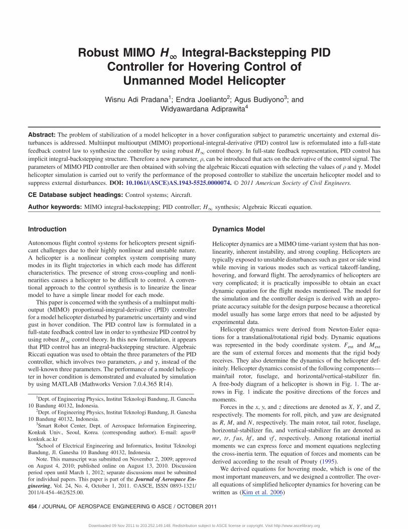
Robust MIMO H∞ Integral-Backstepping PIDController for Hovering Control of
Unmanned Model HelicopterWisnu Adi Pradana1; Endra Joelianto2; Agus Budiyono3; and
Widyawardana Adiprawita4
Abstract: The problem of stabilization of a model helicopter in a hover configuration subject to parametric uncertainty and external dis-turbances is addressed. Multiinput multioutput (MIMO) proportional-integral-derivative (PID) control law is reformulated into a full-statefeedback control law to synthesize the controller by using robust H∞ control theory. In full-state feedback representation, PID control hasimplicit integral-backstepping structure. Therefore a new parameter, ρ, can be introduced that acts on the derivative of the control signal. Theparameters of MIMO PID controller are then obtained with solving the algebraic Riccati equation with selecting the values of ρ and γ. Modelhelicopter simulation is carried out to verify the performance of the proposed controller to stabilize the uncertain helicopter model and tosuppress external disturbances. DOI: 10.1061/(ASCE)AS.1943-5525.0000074. © 2011 American Society of Civil Engineers.
CE Database subject headings: Control systems; Aircraft.
Author keywords: MIMO integral-backstepping; PID controller; H∞ synthesis; Algebraic Riccati equation.
Introduction
Autonomous flight control systems for helicopters present signifi-cant challenges due to their highly nonlinear and unstable nature.A helicopter is a nonlinear complex system comprising manymodes in its flight trajectories in which each mode has differentcharacteristics. The presence of strong cross-coupling and nonli-nearities causes a helicopter to be difficult to control. A conven-tional approach to the control synthesis is to linearize the linearmodel to have a simple linear model for each mode.
This paper is concerned with the synthesis of a multiinput multi-output (MIMO) proportional-integral-derivative (PID) controllerfor a model helicopter disturbed by parametric uncertainty and windgust in hover condition. The PID control law is formulated in afull-state feedback control law in order to synthesize PID control byusing robust H∞ control theory. In this new formulation, it appearsthat PID control has an integral-backstepping structure. AlgebraicRiccati equation was used to obtain the three parameters of the PIDcontroller, which involves two parameters, ρ and γ, instead of thewell-known three parameters. The performance of a model helicop-ter in hover condition is demonstrated and evaluated by simulationby using MATLAB (Mathworks Version 7.0.4.365 R14).
Dynamics Model
Helicopter dynamics are a MIMO time-variant system that has non-linearity, inherent instability, and strong coupling. Helicopters aretypically exposed to unstable disturbances such as gust or side windwhile moving in various modes such as vertical takeoff-landing,hovering, and forward flight. The aerodynamics of helicopters arevery complicated; it is practically impossible to obtain an exactdynamic equation for the flight modes mentioned. The model forthe simulation and the controller design is derived with an appro-priate accuracy suitable for the design purpose because a theoreticalmodel usually has some large errors that need to be adjusted byexperimental data.
Helicopter dynamics were derived from Newton-Euler equa-tions for a translational/rotational rigid body. Dynamic equationswas represented in the body coordinate system. Fext and Mext
are the sum of external forces and moments that the rigid bodyreceives. They also determine the dynamics of the helicopter def-initely. Helicopter dynamics consist of the following components—main/tail rotor, fuselage, and horizontal/vertical-stabilizer fin.A free-body diagram of a helicopter is shown in Fig. 1. The ar-rows in Fig. 1 indicate the positive directions of the forces andmoments.
Forces in the x, y, and z directions are denoted as X, Y , and Z,respectively. The moments for roll, pitch, and yaw are designatedas R, M, and N, respectively. The main rotor, tail rotor, fuselage,horizontal-stabilizer fin, and vertical-stabilizer fin are denoted asmr, tr, f us, hf , and vf , respectively. Among rotational inertialmoments we can express force and moment equations neglectingthe cross-inertia term. The equation of forces and moments can bederived according to the result of Prouty (1995).
We derived equations for hovering mode, which is one of themost important maneuvers, and we designed a controller. The over-all equations of simplified helicopter dynamics for hovering can bewritten as (Kim et al. 2006)
1Dept. of Engineering Physics, Institut Teknologi Bandung, Jl. Ganesha10 Bandung 40132, Indonesia.
2Dept. of Engineering Physics, Institut Teknologi Bandung, Jl. Ganesha10 Bandung 40132, Indonesia.
3Smart Robot Center, Dept. of Aerospace Information Engineering,Konkuk Univ., Seoul, Korea. (corresponding author). E-mail: [email protected]
4School of Electrical Engineering and Informatics, Institut TeknologiBandung, Jl. Ganesha 10 Bandung 40132, Indonesia.
Note. This manuscript was submitted on November 2, 2009; approvedon August 4, 2010; published online on August 13, 2010. Discussionperiod open until March 1, 2012; separate discussions must be submittedfor individual papers. This paper is part of the Journal of Aerospace En-gineering, Vol. 24, No. 4, October 1, 2011. ©ASCE, ISSN 0893-1321/2011/4-454–462/$25.00.
454 / JOURNAL OF AEROSPACE ENGINEERING © ASCE / OCTOBER 2011
Downloaded 09 Nov 2011 to 203.252.149.148. Redistribution subject to ASCE license or copyright. Visit http://www.ascelibrary.org
_Vb ¼1m
�Tmr sin a1s
�Tmr sin b1s � Ttr
�Tmr cos a1s cos b1s þ Zhf þ Zf us
264
375þ RTP→B
0
0
g
264375þ
�vr � wq
�ur þ wp
uq� vp
264
375 ð1Þ
_ω ¼ I�1b
��
dRdb1s
�b1s � Tmrhmr sin b1s � Qmr sin a1s � Tmrymr � Ttrhtr�
dMda1s
�a1s þ Tmrhmr sin a1s � Qmr sin b1s þ Tmrlmr � Qtr þ Zhf lhf
�Qmr cos a1s cos b1s þ Tmr sin b1slmr þ Ttrltr
26664
37775þ I�1
b
qrðIyy � IzzÞprðIzz � IxxÞpqðIxx � IyyÞ
264
375 ð2Þ
It is required to have a linear dynamic model of a helicopter todesign a linear feedback control system. The state-space form ofthe helicopter dynamics can be represented as
_x ¼ Fðx; uÞ ð3Þ
x ¼ ½uvwΦpΘqΨra1sb1s�T ð4Þ
u ¼ ½ulatulonupeducol�T ð5Þ
The linearized system equation is defined as the Jacobian matrices:
δ _x ¼�∂Fj
∂xi�x ¼ xtrimu ¼ utrim
δxþ�∂Fj
∂ui�x ¼ xtrimu ¼ utrim
δu ð6Þ
The Jacobian matrices, often called the stability derivatives, can befound by the partial differentiation of the system equation Fðx; uÞ.Although easily measurable parameters exist, it is usually difficultto measure these values without using special equipment. There-fore, we use a system identification method to find a system modeldirectly by using the flight data. The model will be used to elabo-rate the performance of MIMO PID control.
System Identification
In the following, the template model for the linear time invariant(LTI), MIMO parametric identification is given. The model is pro-posed by Mettler et al. (2002). The model also includes the servorotor (Bell-Hiller stabilizer) dynamics as a first-order approxima-tion. By having the servomotor pulse width modulation (PWM)
Fig. 1. Helicopter free-body diagram (adapted from Shim 2000, with permission)
JOURNAL OF AEROSPACE ENGINEERING © ASCE / OCTOBER 2011 / 455
Downloaded 09 Nov 2011 to 203.252.149.148. Redistribution subject to ASCE license or copyright. Visit http://www.ascelibrary.org
input as the control input, we do not need to identify the servo motor and the linkage gains separately. They are identified as a whole in theidentification process instead of being treated separately. The template model can be written as
_x ¼ Axþ B2u ð7Þ
x ¼ ½uvpqwΦΘa1sb1srΨ�T ð8Þ
u ¼ ½ulatulonupeducol�T ð9Þ
A ¼
Xu 0 0 0 0 �g Xa1s 0 0 0 0
Lu Yv 0 0 g 0 0 Yb1s 0 0 0
0 Lv 0 0 0 0 La1s 0 0 0 0
Mu Mv 0 0 0 0 Ma1s Mb1s 0 0 0
0 0 1 0 0 0 0 0 0 0 0
0 0 0 1 0 0 0 0 0 0 0
0 0 0 �1 0 0 �1=τ f Ab1s 0 0 0
0 0 �1 0 0 0 Ba1s �1=τ f 0 0 0
0 0 0 0 0 0 Za1s Zb1s Zw Zr 0
0 0 Np 0 0 0 0 0 Nw Nr Nrf b
0 0 0 0 0 0 0 0 0 Kr Krf b
26666666666666666666666664
37777777777777777777777775
ð10Þ
B2 ¼
0 0 0 0
0 0 0 0
0 0 0 0
0 0 0 0
0 0 0 0
0 0 0 0
Aulat Aulon 0 0
Bulat Bulon 0 0
0 0 Zuped 0
0 0 Nuped Nucol
0 0 0 0
26666666666666666666666664
37777777777777777777777775
ð11Þ
A MIMO model such as the preceding system can be identifiedwith a number of numerical optimization algorithms. For this re-search the prediction-error method (PEM) in the MATLAB SystemIdentification Toolbox has been chosen (Ljung 2007).
To identify each parameter of the system matrices, we needed tocollect flight data. Once an adequate amount of flight data had beencollected, we identified parameters in the system matrices by usingan identification algorithm. Before feeding the data into the numeri-cal tool the data are preprocessed, and the angular rate measure-ments are filtered to eliminate high-frequency noise. The roll andpitch angle measurements are de-trended to remove the mean val-ues because the helicopter has a trim condition (the equilibriumwith certain nonzero states).
This system identification method is extremely sensitive to theinitial guess of the parameters. It can also be easily trapped in alocal minimum in the parameter hypersurface. To obtain meaning-ful results while avoiding these difficulties, we used the followingtechnique (Shim et al. 2000).
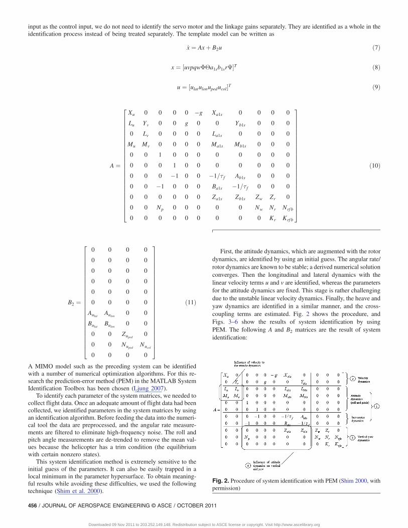
First, the attitude dynamics, which are augmented with the rotordynamics, are identified by using an initial guess. The angular rate/rotor dynamics are known to be stable; a derived numerical solutionconverges. Then the longitudinal and lateral dynamics with thelinear velocity terms u and v are identified, whereas the parametersfor the attitude dynamics are fixed. This stage is rather challengingdue to the unstable linear velocity dynamics. Finally, the heave andyaw dynamics are identified in a similar manner, and the cross-coupling terms are estimated. Fig. 2 shows the procedure, andFigs. 3–6 show the results of system identification by usingPEM. The following A and B2 matrices are the result of systemidentification:
Fig. 2. Procedure of system identification with PEM (Shim 2000, withpermission)
456 / JOURNAL OF AEROSPACE ENGINEERING © ASCE / OCTOBER 2011
Downloaded 09 Nov 2011 to 203.252.149.148. Redistribution subject to ASCE license or copyright. Visit http://www.ascelibrary.org
A ¼
�0:2018 0 0 0 0 �32:2 �32:2 0 0 0 00 0:0149 0 0 32:2 0 0 32:2 0 0 0
�0:1464 �0:0578 0 0 0 0 4:6882 69:952 0 0 00:0882 �0:1184 0 0 0 0 50:839 12:138 0 0 0
0 0 1 0 0 0 0 0 0 0 00 0 0 1 0 0 0 0 0 0 00 0 0 �1 0 0 �5:9549 �1:7605 0 0 00 0 �1 0 0 0 �0:3163 �8:2545 0 0 00 0 0 0 0 0 �3:0198 18:33 �166:04 112:54 00 0 �1:2743 0 0 0 0 0 �27:07 10:378 �44:4770 0 0 0 0 0 0 0 0 �0:368 �5:1536
266666666666666664
377777777777777775
B2 ¼
0 0 0 00 0 0 00 0 0 00 0 0 00 0 0 00 0 0 0
4:0375 �8:9405 0 09:6244 3:0024 0 0
0 0 15:133 00 0 117:6 44:8730 0 0 0
266666666666666664
377777777777777775
State Feedback Representation of PID Control
To design with robust control theory, the PID controller needs tobe expressed as a full-state feedback control law (Joelianto 2000;Joelianto et al. 2003, 2008). Consider a MIMO LTI system given by
_x ¼ Axþ B2u y ¼ C2x ð12Þ
and the states x ∈ Rn are the solution of Eq. (12): the control signalu ∈ Rl is assumed to be the output of a PID controller with inputy ∈ Rm. Matrices A, B2, and C2 are matrices with appropriatedimension. The PID control for tracking problem is
uðtÞ ¼ K1
Zt
0eðtÞdt þ K2eðtÞ þ K3
ddt
eðtÞ ð13Þ
with eðtÞ ¼ yðtÞ � rðtÞ. The parameters K1, K2, and K3 ∈ Rl×m arematrices to be designed. The structure in Eq. (13) is known as thestandard PID controller or ISA form. According to the InternalModel Principle or IMP (Joelianto 2000), the solution for a lineartime invariant system is a reference signal in the form of step input
_xrðtÞ ¼ AxrðtÞ; xrðtÞ ∈ Rn; rðtÞ ¼ C2xrðtÞ ð14Þ
Defined state tracking error z and output tracking error e are asfollows:
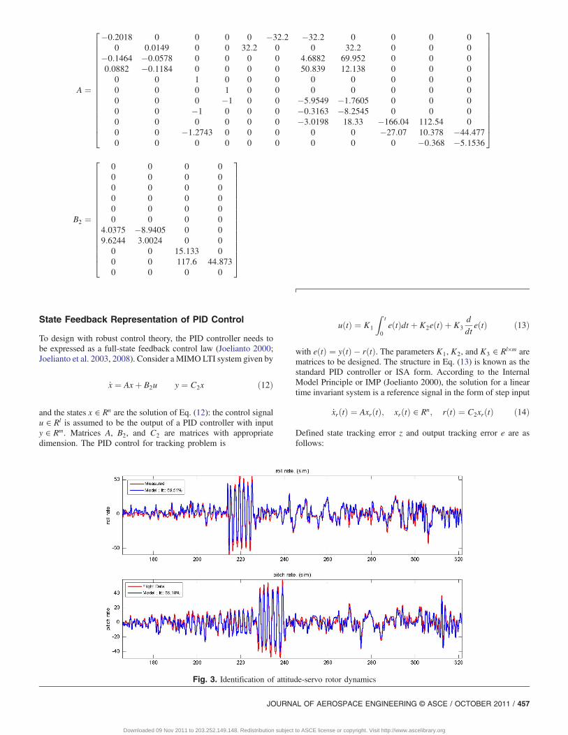
Fig. 3. Identification of attitude-servo rotor dynamics
JOURNAL OF AEROSPACE ENGINEERING © ASCE / OCTOBER 2011 / 457
Downloaded 09 Nov 2011 to 203.252.149.148. Redistribution subject to ASCE license or copyright. Visit http://www.ascelibrary.org
zðtÞ ¼ xðtÞ � xrðtÞ ð15Þ
e ¼ yðtÞ � rðtÞ ð16ÞAfter differentiating Eq. (15) and then substituting Eqs. (12) and (14)for Eqs. (15) and (16), the result is the state-space equation fortracking error system:
_zðtÞ ¼ AzðtÞ þ B2uðtÞ; zðtÞ ∈ Rn; eðtÞ ¼ C2zðtÞ ð17ÞWhen Eq. (17) is differentiated twice, the results is
eðtÞ ¼ C2zðtÞ_eðtÞ ¼ C2AzðtÞ þ C2B2uðtÞ€eðtÞ ¼ C2A2zðtÞ þ C2AB2uðtÞ þ C2B2 _uðtÞ
ð18Þ
The control law [Eq. (13)] may be written as
ðl� K3C2B2Þ _uðtÞ ¼0@½K1K2K3�
C2
C2AC2A2
24
351AzðtÞ
þ0@½K1K2K3�
0C2B2
C2AB2
24
351AuðtÞ ð19Þ
The notation K̂ as a normalization of K can be written in themore compact form
K̂ ¼ ½K̂1K̂2K̂3� ¼ ðl� K3C2B2Þ�1½K1K2K3� ð20Þ
This control law is then given by
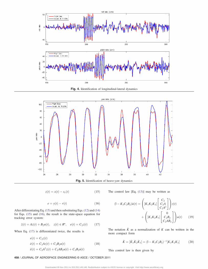
Fig. 4. Identification of longitudinal-lateral dynamics
Fig. 5. Identification of heave-yaw dynamics
458 / JOURNAL OF AEROSPACE ENGINEERING © ASCE / OCTOBER 2011
Downloaded 09 Nov 2011 to 203.252.149.148. Redistribution subject to ASCE license or copyright. Visit http://www.ascelibrary.org
_uðtÞ ¼0@K̂
C2
C2AC2A2
24
351AzðtÞ þ
0@K̂
0C2B2
C2AB2
24
351AuðtÞ ð21Þ
Denote Kx¼ K̂T ½CT2A
TCT2ðA2ÞTCT
2 �T and Ku¼K̂T ½0BT2C
T2B
T2A
TCT2 �T ,
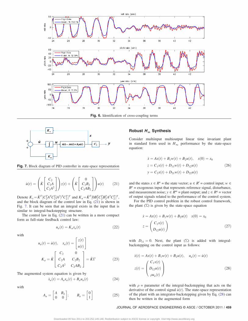
and the block diagram of the control law in Eq. (21) is shown inFig. 7. It can be seen that an integral exists in the input that issimilar to integral-backstepping structure.
The control law in Eq. (21) can be written in a more compactform as full-state feedback control law:
uaðtÞ ¼ KaxaðtÞ ð22Þwith
uaðtÞ ¼ _uðtÞ; xaðtÞ ¼zðtÞuðtÞ
" #
Ka ¼ K̂
C2
C2A
C2A2
0
C2B2
C2AB2
264
375 ¼ K̂Γ ð23Þ
The augmented system equation is given by
_xaðtÞ ¼ AaxaðtÞ þ BauaðtÞ ð24Þwith
Aa ¼ A B2
0 0
� �; Ba ¼ 0
l
� �ð25Þ
Robust H∞ Synthesis
Consider multiinput multioutput linear time invariant plantin standard form used in H∞ performance by the state-spaceequation:
_x ¼ AxðtÞ þ B1wðtÞ þ B2uðtÞ; xð0Þ ¼ x0
z ¼ C1xðtÞ þ D11wðtÞ þ D12uðtÞy ¼ C2xðtÞ þ D21wðtÞ þ D22uðtÞ
ð26Þ
and the states x ∈ Rn = the state vector; u ∈ Rl = control input; w ∈Rp = exogenous input that represents reference signal, disturbance,and measurement noise; y ∈ Rm = plant output; and z ∈ Rq = vectorof output signals related to the performance of the control system.
For the PID control problem in the robust control framework,the plant (Σ) is given by the state-space equation
_x ¼ AxðtÞ þ B1wðtÞ þ B2uðtÞ xð0Þ ¼ x0
z ¼ C1xðtÞD12uðtÞ
!ð27Þ
with D11 ¼ 0. Next, the plant (Σ) is added with integral-backstepping on the control input as follows:
_xðtÞ ¼ AxðtÞ þ B1wðtÞ þ B2uðtÞ; uaðtÞ ¼ _uðtÞ
zðtÞ ¼C1xðtÞD12uðtÞρuaðtÞ
0B@
1CA ð28Þ
with ρ = parameter of the integral-backstepping that acts on thederivative of the control signal _uðtÞ. The state-space representationof the plant with an integrator-backstepping given by Eq. (28) canthen be written in the augmented form
Fig. 6. Identification of cross-coupling terms
Fig. 7. Block diagram of PID controller in state-space representation
JOURNAL OF AEROSPACE ENGINEERING © ASCE / OCTOBER 2011 / 459
Downloaded 09 Nov 2011 to 203.252.149.148. Redistribution subject to ASCE license or copyright. Visit http://www.ascelibrary.org
_xðtÞ_uðtÞ
" #¼�A B2
0 0
�xðtÞuðtÞ
" #þ�B1
0
�wðtÞ þ
�0
1
�uaðtÞ
_xaðtÞ ¼ AaxaðtÞ þ B1awðtÞ þ B2auaðtÞ
zðtÞ ¼C1
0
0
0
D12
0
264
375 xðtÞ
uðtÞ
" #þ
0
0
ρ
264375uaðtÞ
zðtÞ ¼ CaxaðtÞ þ D2auaðtÞ ð29ÞThe following theorem is an extension of the single-input single-output (SISO) result in Hill et al. (1977), Joelianto (2003, 2008),and Yuliar et al. (1998) that gives the existence condition and theformula of the stabilizing gain feedback Ka.
Theorem 1
Given γ > 0 and ρ > 0. If there exists X ¼ XT > 0 of the followingalgebraic Riccati equation:
XAa þ ATaX � Xðρ�2B2aBT
2a � γ�2B1aBT1aÞX þ CT
aCa ¼ 0 ð30Þthen the full-state feedback gain
Ka ¼ �ρ�2BTaX ð31Þ
leads tokΣzwk∞ < γ ð32Þ
The theorem assumes that the following conditions hold (Greenet al. 1995):
ðA;B2aÞ ð33Þis able to be stabilized, and
ðA;CaÞ ð34Þhas no unobservable mode on the imaginary axis.
Simulation Results
The simulations are carried out within the MATLAB m-file envi-ronment by using the dynamic model of unmanned helicopter inhovering mode. The state and measurement vectors are selectedas (Valavanis 2007)
x ¼ ½uvpqwΦΘa1sb1srΨ�T y ¼ ½ΦΘrw�T ð35Þ
The state initial value is ½0; 0; 0; 0; 0; 0:1 rad; 0:1 rad; 0; 0; 0; 0�T .The model is subject to parametric uncertainty and wind gustdisturbance. For parametric uncertainty in the state-space model,two stability derivatives were chosen, Xu (Budiyono 2008) andMu (Natesan et al. 2006). The parameters were set to have 50%uncertainty from their nominal value. Wind gust disturbancesare represented by a sine function (Kadmiry 2002) with amplitudeA¼3:3 ft=s and angular velocity ω¼ 0:628 rad=s. The PID param-eters are obtained by solving algebraic Riccati equation that yields
Kp ¼
�0:52 �0:99 �0:165 �0:876
0:107 �0:426 0:006 0:084
1:96 0:604 2:975 0:854
�2:35 �0:87 0:027 �1:322
266664
377775;
Ki ¼
8:196 0:6614 �2:336 �13:507
1:915 �10:489 0:0866 1:2193
3:133 �0:047 43:416 14:01
�3:895 �0:499 0:1512 �20:309
266664
377775;
Kd ¼
0:0351 �0:1749 �0:006 �0:0256
0:0005 �0:012 0:0002 0:0025
0:0768 �0:1079 0:099 0:0263
�0:2401 �0:1531 0:002 �0:0234
266664
377775 ð36Þ
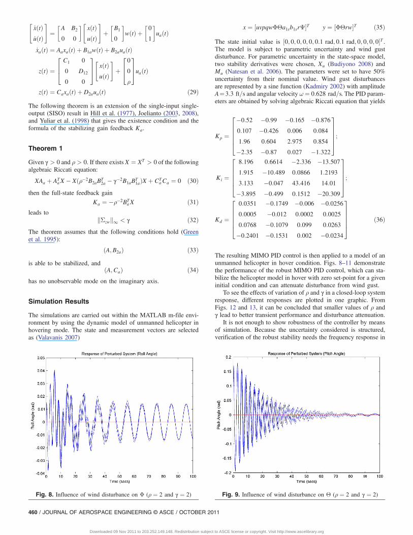
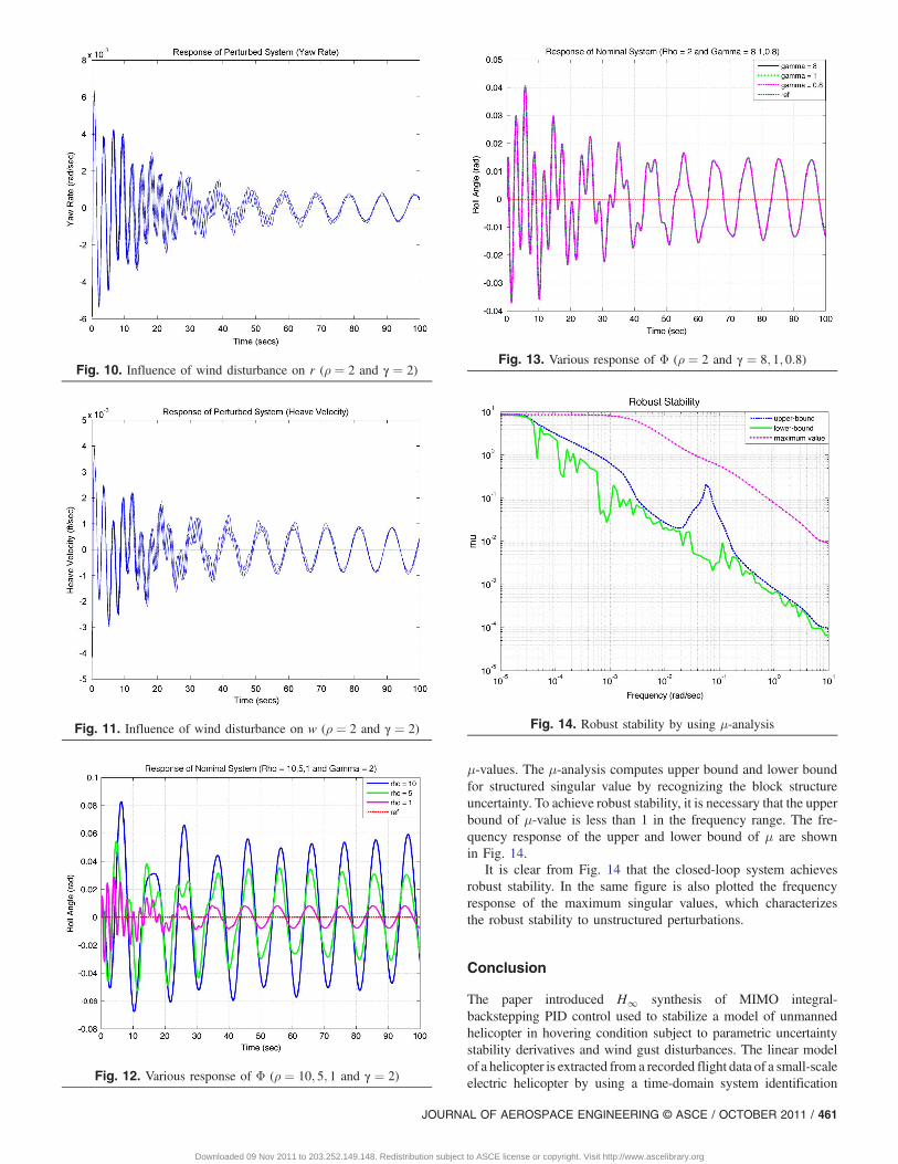
The resulting MIMO PID control is then applied to a model of anunmanned helicopter in hover condition. Figs. 8–11 demonstratethe performance of the robust MIMO PID control, which can sta-bilize the helicopter model in hover with zero set-point for a giveninitial condition and can attenuate disturbance from wind gust.
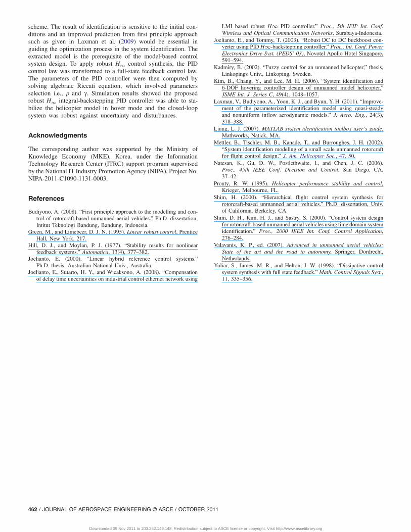
To see the effects of variation of ρ and γ in a closed-loop systemresponse, different responses are plotted in one graphic. FromFigs. 12 and 13, it can be concluded that smaller values of ρ andγ lead to better transient performance and disturbance attenuation.
It is not enough to show robustness of the controller by meansof simulation. Because the uncertainty considered is structured,verification of the robust stability needs the frequency response in
Fig. 8. Influence of wind disturbance on Φ (ρ ¼ 2 and γ ¼ 2) Fig. 9. Influence of wind disturbance on Θ (ρ ¼ 2 and γ ¼ 2)
460 / JOURNAL OF AEROSPACE ENGINEERING © ASCE / OCTOBER 2011
Downloaded 09 Nov 2011 to 203.252.149.148. Redistribution subject to ASCE license or copyright. Visit http://www.ascelibrary.org
μ-values. The μ-analysis computes upper bound and lower boundfor structured singular value by recognizing the block structureuncertainty. To achieve robust stability, it is necessary that the upperbound of μ-value is less than 1 in the frequency range. The fre-quency response of the upper and lower bound of μ are shownin Fig. 14.
It is clear from Fig. 14 that the closed-loop system achievesrobust stability. In the same figure is also plotted the frequencyresponse of the maximum singular values, which characterizesthe robust stability to unstructured perturbations.
Conclusion
The paper introduced H∞ synthesis of MIMO integral-backstepping PID control used to stabilize a model of unmannedhelicopter in hovering condition subject to parametric uncertaintystability derivatives and wind gust disturbances. The linear modelof a helicopter is extracted from a recorded flight data of a small-scaleelectric helicopter by using a time-domain system identification
Fig. 10. Influence of wind disturbance on r (ρ ¼ 2 and γ ¼ 2)
Fig. 11. Influence of wind disturbance on w (ρ ¼ 2 and γ ¼ 2)
Fig. 12. Various response of Φ (ρ ¼ 10; 5; 1 and γ ¼ 2)
Fig. 13. Various response of Φ (ρ ¼ 2 and γ ¼ 8; 1; 0:8)
Fig. 14. Robust stability by using μ-analysis
JOURNAL OF AEROSPACE ENGINEERING © ASCE / OCTOBER 2011 / 461
Downloaded 09 Nov 2011 to 203.252.149.148. Redistribution subject to ASCE license or copyright. Visit http://www.ascelibrary.org
scheme. The result of identification is sensitive to the initial con-ditions and an improved prediction from first principle approachsuch as given in Laxman et al. (2009) would be essential inguiding the optimization process in the system identification. Theextracted model is the prerequisite of the model-based controlsystem design. To apply robust H∞ control synthesis, the PIDcontrol law was transformed to a full-state feedback control law.The parameters of the PID controller were then computed bysolving algebraic Riccati equation, which involved parametersselection i.e., ρ and γ. Simulation results showed the proposedrobust H∞ integral-backstepping PID controller was able to sta-bilize the helicopter model in hover mode and the closed-loopsystem was robust against uncertainty and disturbances.
Acknowledgments
The corresponding author was supported by the Ministry ofKnowledge Economy (MKE), Korea, under the InformationTechnology Research Center (ITRC) support program supervisedby the National IT Industry Promotion Agency (NIPA), Project No.NIPA-2011-C1090-1131-0003.
References
Budiyono, A. (2008). “First principle approach to the modelling and con-trol of rotorcraft-based unmanned aerial vehicles.” Ph.D. dissertation,Intitut Teknologi Bandung, Bandung, Indonesia.
Green, M., and Limebeer, D. J. N. (1995). Linear robust control, PrenticeHall, New York, 217.
Hill, D. J., and Moylan, P. J. (1977). “Stability results for nonlinearfeedback systems.” Automatica, 13(4), 377–382.
Joelianto, E. (2000). “Linear hybrid reference control systems.”Ph.D. thesis, Australian National Univ., Australia.
Joelianto, E., Sutarto, H. Y., and Wicaksono, A. (2008). “Compensationof delay time uncertainties on industrial control ethernet network using
LMI based robust H∞ PID controller.” Proc., 5th IFIP Int. Conf.Wireless and Optical Communication Networks, Surabaya-Indonesia.
Joelianto, E., and Tommy, T. (2003). “Robust DC to DC buckboost con-verter using PID H∞-backstepping controller.” Proc., Int. Conf. PowerElectronics Drive Syst. (PEDS’ 03), Novotel Apollo Hotel Singapore,591–594.
Kadmiry, B. (2002). “Fuzzy control for an unmanned helicopter,” thesis,Linkopings Univ., Linkoping, Sweden.
Kim, B., Chang, Y., and Lee, M. H. (2006). “System identification and6-DOF hovering controller design of unmanned model helicopter.”JSME Int. J. Series C, 49(4), 1048–1057.
Laxman, V., Budiyono, A., Yoon, K. J., and Byun, Y. H. (2011). “Improve-ment of the parameterized identification model using quasi-steadyand nonuniform inflow aerodynamic models.” J. Aero. Eng., 24(3),378–388.
Ljung, L. J. (2007). MATLAB system identification toolbox user’s guide,Mathworks, Natick, MA.
Mettler, B., Tischler, M. B., Kanade, T., and Burroughes, J. H. (2002).“System identification modeling of a small scale unmanned rotorcraftfor flight control design.” J. Am. Helicopter Soc., 47, 50.
Natesan, K., Gu, D. W., Postlethwaite, I., and Chen, J. C. (2006).Proc., 45th IEEE Conf. Decision and Control, San Diego, CA,37–42.
Prouty, R. W. (1995). Helicopter performance stability and control,Krieger, Melbourne, FL.
Shim, H. (2000). “Hierarchical flight control system synthesis forrotorcraft-based unmanned aerial vehicles.” Ph.D. dissertation, Univ.of California, Berkeley, CA.
Shim, D. H., Kim, H. J., and Sastry, S. (2000). “Control system designfor rotorcraft-based unmanned aerial vehicles using time domain systemidentification.” Proc., 2000 IEEE Int. Conf. Control Application,276–284.
Valavanis, K. P., ed. (2007). Advanced in unmanned aerial vehicles:State of the art and the road to autonomy, Springer, Dordrecht,Netherlands.
Yuliar, S., James, M. R., and Helton, J. W. (1998). “Dissipative controlsystem synthesis with full state feedback.” Math. Control Signals Syst.,11, 335–356.
462 / JOURNAL OF AEROSPACE ENGINEERING © ASCE / OCTOBER 2011
Downloaded 09 Nov 2011 to 203.252.149.148. Redistribution subject to ASCE license or copyright. Visit http://www.ascelibrary.org
Copyright © 2022 FDOKUMEN