Feature Correspondence and Deformable Object Matching via Agglomerative Correspondence Clustering

Robust Feature Extraction and Matching forOmnidirectional Images
Davide Scaramuzza1, Nicolas Criblez2, Agostino Martinelli3, and RolandSiegwart4
1 Swiss Federal Institute of Technology Zurich [email protected] Swiss Federal Institute of Technology Lausanne [email protected] INRIA [email protected] Swiss Federal Institute of Technology Zurich [email protected]
Summary. This paper presents a new and robust method for extracting and match-ing visual vertical features between images taken by an omnidirectional camera.Matching robustness is achieved by creating a descriptor which is unique and dis-tinctive for each feature. Furthermore, the proposed descriptor is invariant to ro-tation. The robustness of the approach is validated through real experiments witha wheeled robot equipped with an omnidirectional camera. We show that verticallines are very well extracted and tracked during the robot motion. At the end, wealso present an application of our algorithm to the robot simultaneous localizationand mapping in an unknown environment.
1 Introduction
One of the most important problems in vision based robot navigation systemsis the search for correspondences in images taken from different viewpoints.In the last decades, the feature correspondence problem has been largely in-vestigated for standard perspective cameras. Furthermore, some works haveprovided robust solutions for wide-baseline stereo matching, structure frommotion, ego-motion estimation, and robot navigation (see [1], [2], [3], [4], [5],[6], [7], [8], and [9]). Some of these works normalize the region around eachdetected feature using a local affine transformation, which attempts to com-pensate for the distortion introduced by the perspective projection. However,such methods cannot be directly applied to images taken by omnidirectionalimaging devices because of the non-linear distortions introduced by their largefield of view. In order to apply those methods, one needs first to generate aperspective view out of the omnidirectional image, provided that the imag-ing model is known and that the omnidirectional camera possesses a singleeffective viewpoint [10]. An application of this approach can be found in [11].There, the authors generate perspective views from each region of interest of

2 Authors Suppressed Due to Excessive Length
the omnidirectional image. This image unwrapping removes the distortionsof the omnidirectional imaging device and enables the use of state-of-the-art wide-baseline algorithms designed for perspective cameras. Nevertheless,other researchers have attempted to apply to omnidirectional images stan-dard feature detectors and matching techniques, which have been tradition-ally employed for perspective images. In [15], for instance, the authors checkthe candidate correspondences between two views using RANSAC algorithm.Finally, other works have been developed, which extract one-dimensional fea-tures from new images called Epipolar plane images, under the assumptionthat the camera is moving on a flat surface [16]. These images are generatedby converting each omnidirectional picture into a 1D circular image, whichis obtained by averaging the scan lines of a cylindrical panorama. Then, 1Dfeatures are extracted directly from such kinds of images.In this paper, the features we want to track from omnidirectional imagesare real world vertical features, which are predominant in structured envi-ronments. In our experiments, we used a wheeled robot equipped with anomnidirectional camera, which had the camera axis perpendicular to the di-rection of motion of the robot. Because of this settings and assuming theenvironment to be flat, all world vertical lines project into radial lines on theimage plane.The novelty of this paper consists of a robust method to match vertical linesbetween images taken by an omnidirectional camera during the motion ofthe robot. Matching robustness is achieved by creating a descriptor which isunique and distinctive for each feature. Furthermore, the proposed descriptoris invariant to rotation. This descriptor is based on the image gradients. Therobustness of the approach was validated through real experiments by using arobot equipped with an omnidirectional camera. In this paper, we show thatvertical lines are very well extracted and tracked during the robot motion. Atthe end, we also present an application of our algorithm to the robot Simul-taneous Localization And Mapping (SLAM) in an unknown environment.This paper is organized as follows. In section 2, we will discuss the verti-cal line extraction. In section 3, we will illustrate how to mark a feature bymeans of a descriptor, and, in section 4, we will describe the feature matchingprocess. Finally, in section 5, we will present our experimental results and theapplication of our algorithm to SLAM.
2 Vertical Line Extraction
Our platform consists of a wheeled robot equipped with an omnidirectionalcamera looking upwards. The main advantage of such kind of camera is thatit provides a 360◦ field of view of the scene, which gives a very rich and sparseinformation.Figure 1 shows a sample picture taken by our omnidirectional camera. As thecircular external boundary of the mirror is visible in the image, we use a circle

Robust Feature Extraction and Matching for Omnidirectional Images 3
detector to determine the location of the center.In our arrangement, we set the camera-mirror system perpendicular to thefloor where the robot moves. This guarantees that all vertical lines of the en-vironment converge towards the image center. To extract the vertical lines,we first compute the image gradients (e.g. we used a Sobel filter), and then wekeep only those gradients whose orientation looks towards the image centerup to ±5◦. This 10◦ tolerance allows us to deal with the effects of the floorirregularities in the projections of the 3D vertical lines. After this filtering, weapply non-maxima suppression and we end up with a binary edge map (Fig.2).The next step will be identifying the most reliable vertical lines. To thisend, we divide the omnidirectional image into 720 predefined uniform sec-tors, which give us an angular resolution of 0.5◦. By summing up all binarypixels that vote for the same sector, we obtain the histogram shown in Fig. 3.As observed in Fig. 2, there are many potential vertical lines in a structuredenvironment. To keep the most reliable and robust features, we choose onlythose lines whose length covers at least half of the angle of view (Fig. 3).Finally, we use non-maxima suppression to avoid the features to be too close(Fig. 4).
Fig. 1. An image taken by our omni-directional camera.
Fig. 2. The final binary edge map afternon-maxima suppression.
3 Building the Descriptor
In section 4, we will describe our method for matching vertical lines betweenconsecutive frames while the robot is moving in an unknown environment.To make the feature correspondence robust to false positives, each verticalline is given a descriptor, which is unique and distinctive for each feature.Furthermore, this descriptor is invariant to rotation. In this way, finding thecorrespondent of a vertical line can be done by looking for the line with the

4 Authors Suppressed Due to Excessive Length
Fig. 3. The number of binary pixels vot-ing for a given orientation angle. The ori-entation axis ranges from 0 to 720 half de-grees.
Fig. 4. Extraction of the most reliablevertical features from an omnidirectionalimage.
closest descriptor. In the next subsections, we will describe how to build thisdescriptor.
3.1 Rotation Invariance
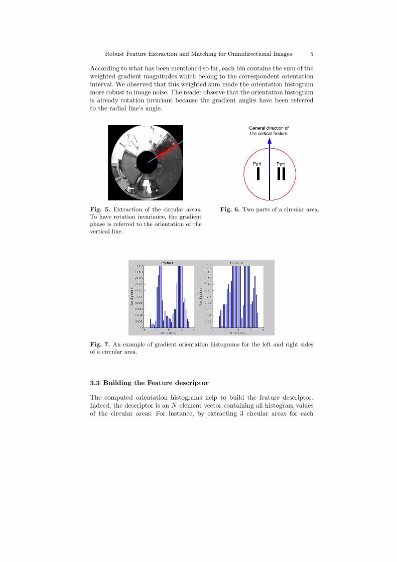
To build the descriptor, we extract a predefined number of circular areas(namely 3 areas) in fixed position along a given radial line (Fig. 5). Thecenters of these circular areas are equally spaced and the radius is chosensuch that the circles touch without overlapping. Then, each area is smoothedby a Gaussian window of variance σ and the image gradients (magnitude andphase) are computed within each of these areas. The rotation invariance isachieved redefining the gradient phase relatively to the radial line’s angle.(Fig. 5).
3.2 Orientation Histograms
To make the descriptor robust to false matches, we split each circular areainto two parts and consider each one individually (Fig. 6). In this way, wepreserve the information about what we have on the left and right sides ofthe feature. For each side of each circular area, we compute an orientationhistogram (Fig. 7) of all gradient vectors. The whole orientation space (from-π to π) is divided into Nb equally spaced bins. In order to decide how muchof a certain gradient magnitude m belongs to the adjacent inferior bin b andhow much to the adjacent superior bin, each magnitude m is weighted by thefactor (1− w), where
w = Nb · o− b
2π(1)
with o being the observed orientation in radians. Thus, m(1 − w) will votefor the adjacent inferior bin, while mw will vote for the adjacent superior bin.
Robust Feature Extraction and Matching for Omnidirectional Images 5
According to what has been mentioned so far, each bin contains the sum of theweighted gradient magnitudes which belong to the correspondent orientationinterval. We observed that this weighted sum made the orientation histogrammore robust to image noise. The reader observe that the orientation histogramis already rotation invariant because the gradient angles have been referredto the radial line’s angle.
Fig. 5. Extraction of the circular areas.To have rotation invariance, the gradientphase is referred to the orientation of thevertical line.
Fig. 6. Two parts of a circular area.
Fig. 7. An example of gradient orientation histograms for the left and right sidesof a circular area.
3.3 Building the Feature descriptor
The computed orientation histograms help to build the feature descriptor.Indeed, the descriptor is an N -element vector containing all histogram valuesof the circular areas. For instance, by extracting 3 circular areas for each

6 Authors Suppressed Due to Excessive Length
vertical feature and choosing 30 bins for each histogram, the length of thefeature descriptor will be
N = 3areas · 2parts · 30bins = 180 (2)
Finally, it is important to know that all feature descriptors have the samelength N . To achieve slight illumination invariance, every descriptor is nor-malized to 1. This choice relies on the hypothesis that the image intensitychanges linearly with illumination. Although this is not true in nature, thisapproximation proved to work properly.
4 Feature Matching
As every vertical feature has its own descriptor, the correspondent of a verticalline in the consecutive images can be searched among the features with theclosest descriptor. As a distance measure between two vector descriptors Aand B, we use the Euclidean distance:
d(A,B) =
√√√√N∑
k=1
(A(k)−B(k))2 (3)
As a consequence, the correspondent of a feature, in the current image, isexpected to be the one, in the consecutive image, with the minimum distance.However, if a feature is no longer present in the next image, there will be aclosest feature anyway. For this reason, we define three tests to decide whethera feature correspondent exists and which the correspondent is. Before describ-ing the three criterions, let us introduce some definitions.Say {A1,A2, ...,ANA
} and {B1,B2, ...,BNB} two sets of feature descriptors
extracted at time t and t− 1 respectively (where NA and NB are the numberof features in the first and second image). Then, say
Di = {d(Ai,Bj), j = 1, 2, ..., NB)} (4)
the set of all distances between a given Ai and all Bj (j = 1, 2, , NB). Finally,say minDi = min(Di) the minimum of the distances between Ai and all Bj.
First Test
The first test checks that the distance from the closest descriptor is smallerthan a given threshold. As the threshold depends on the length of the descrip-tor, we set
minDi = F1 ·N (5)
where N is the descriptor length. By this criterion, we actually set a boundfor the maximum acceptable distance to the closest descriptor.

Robust Feature Extraction and Matching for Omnidirectional Images 7
Second Test
The second test checks that the distance from the closest descriptor is smallerenough than the mean of the distances from all other descriptors, that is:
minDi = F2· < Di > (6)
where < Di > is the mean value of Di and F2 clearly ranges from 0 to1. This criterion comes out of experimental results. In Table 1, we show areal comparison among the distances between the descriptor A1 at time tand all the descriptors at time t − 1. There, the descriptor B1 is the correctcorrespondent of A1. The reader might also observe that its distance is smallerthan the mean of all other distances.
Table 1. The distances between the descriptor A1 at time t and all descriptors Bj
, j = 1, 2, .., NB at time t− 1
B1 B2 B3 B4 B5 B6 B7
2.38 5.42 4.55 5.79 5.66 6.17 5.43
Third Test
Finally, the third test checks that the distance from the closest descriptor issmaller than the distance from the second closest descriptor:
minDi = F3 · SecondSmallestDistance, (7)
where F3 clearly ranges from 0 to 1. As in the previous test, the third testraises from the observation that, if the correct correspondence exists, thenthere must be a big jump between the closest and the second closest descriptor.Factors F1, F2, and F3 are to be determined experimentally. The empiricalvalues we used for these parameters are shown in Table 2.
Table 2. The parameters used by our algorithm with their empirical values
F1 = 0.0075 F2 = 0.55 F3 = 0.85
5 Experimental Results
In this section, we present some experimental results obtained by movingour robot in a real indoor environment. In the first subsection, we show theperformance of our feature tracker during the motion of the robot, while inthe second one, we present the results of our feature tracker applied to SLAM.In these experiments, the robot was moving at about 0.15 m/s. The imagesize was 640x480 pixels and the frame rate was 3 Hz.

8 Authors Suppressed Due to Excessive Length
5.1 Performance of the Feature Tracking
In this experiment, we guided our robot through an office-like environment forabout 70 meters. The results of the feature tracking are shown in Fig. 8. Theplot refers to a short path of the whole trajectory while the robot was copingwith an L-shaped trajectory. As the reader may observe, many features aredetected and tracked over the time. Indeed, all lines of the plot appear to besmooth and homogeneous. Furthermore, the lines do not intersect, meaningthat there was no false matching. We can also notice that the algorithm wasable to match vertical elements even when the correspondent features were notobserved in the previous image (e.g. observe the large gap between the dotspointed to by the arrow in Fig. 8). Indeed, when the correspondence is notfound in the last frame, our algorithm starts looking into all previous frames(actually up to the twentieth frame), and stops when the correspondenceis found. By zooming into the plot of Fig. 8, we found that some lines aregiven different numbers. For instance, feature number 24 is labeled as 31after some frames. And the same happens with features 42 and 49. When thishappens, it means that the algorithm found no correspondence for the currentfeature, and thus, the feature is labeled as a new entry, but in fact this is afalse new entry. After having visually checked every single frame of the videosequence, we found 6 false matches and 22 false new entries. Comparing theseerrors to the 2631 corresponding pairs detected by the algorithm over thewhole video sequence, we had 1.06% of mismatches. Furthermore, we foundthat the false matches occurred every time the camera was facing objectswith repetitive texture. Thus, the ambiguity was caused by the presence ofvertical elements which were almost identical. On the other hand, a few offalse new entries occurred whenever the displacement of the robot betweentwo successive images was big. However, the reader should observe that whena feature matches with no other previous feature of the last frames, it is betterto believe this feature to be new rather than commit a false matching.
5.2 Application to SLAM
We applied our feature tracker to two important problems in autonomousnavigation, that is, sensor self-calibration and SLAM. Regarding the former,the results can be found in [12], [13], and [14]. In this section, we show onlythe results we obtained for SLAM. We implemented the standard EKF basedSLAM. In particular, the EKF estimates the vector:
X = [xr, yr, θr, X1, Y1, ..., XNO, YNO
]T (8)
where [xr, yr, θr] is the robot configuration, Xi, Yi are the Cartesian coordi-nates of the i-feature in the map, and NO is the number of observed features.Our mobile robot is equipped with wheel encoders and with the same omni-directional camera adopted in the experiments described in section 5.1. The

Robust Feature Extraction and Matching for Omnidirectional Images 9
Fig. 8. Feature tracking during the robot motion. In y-axis, we have the angle ofsight of each feature, and in the x-axis, the frame number. Each dot represents afeature detected in the current frame. The lines represent the tracked features. Thenumber reported on some dot appears only when a new feature is detected.
bearing observations provided by the omnidirectional camera consist of thevector z whose components are:
z1 = arctan(Y1 − yr
X1 − xr)
... (9)
zNO= arctan(
YNO − yr
XNO − xr)
To initialize a new feature in the map, consecutive bearing observations as in[14], which refer to the same feature, are integrated with the odometry. Then,the estimation is improved by integrating the information coming from all thebearing observations through the EKF. The result is shown in Fig. 9 whereboth the robot trajectory and the position of the features are shown.
6 Conclusion
In this paper we introduced and discussed a new and robust method to ex-tract and match vertical lines between images taken by an omnidirectionalcamera. The basic idea to achieve robust feature matching consists of creat-ing a descriptor which is unique and distinctive for each feature. Furthermore,this descriptor is invariant to rotation. To evaluate the performance of our ap-proach, we performed real experiments where we evaluated the quality of the

10 Authors Suppressed Due to Excessive Length
Fig. 9. The results obtained by implementing a simple EKF-SLAM, which uses theproposed feature tracker. The black line is the trajectory estimated by using theodometry alone. The red line is the trajectory estimated by the EKF using boththe odometry and vertical lines. The blue points represent the map ground truthprovided by a laser range finder. The red circles are the detected verticals features.
matching. We conclude that the proposed approach is very robust and pre-cise. Finally, we adopted the proposed method to implement an EKF basedSLAM.
7 Acknowledgment
This work was conducted within the EU Integrated Projects COGNIRON(The Cognitive Robot Companion) and BACS (Bayesian Approach to Cogni-tive Systems). It was funded by the European Commission Division FP6-ISTFuture and Emerging Technologies under the contracts FP6-IST-002020 andFP6-IST-027140 respectively.
References
1. J. Matas, O. Chum, M. Urban, and T. Pajdla. Robust wide baseline stereofrom maximally stable extremal regions. In Proc. 13th British Machine VisionConference,Cardiff, UK, pages 384-393, 2002.
2. T. Kadir, A. Zisserman, and M. Brady. An affine invariant salient region de-tector. In Proc. 7th European Conference on Computer Vision, Prague, CzechRepublic, pages Vol I: 228-241, 2004.
3. Krystian Mikolajczyk and Cordelia Schmid. Indexing based on scale invariantinterest points. In Proceedingsof the 8th International Conference on ComputerVision, Vancouver, Canada, pages 525-531, 2001.
4. D.G. Lowe. Distinctive image features from scale-invariant keypoints. Interna-tional Journal of Computer Vision, 60(2):91-110, November 2004.

Robust Feature Extraction and Matching for Omnidirectional Images 11
5. T. Lindeberg. Feature detection with automatic scale selection. InternationalJournal of Computer Vision, 30(2):79-116, 1998.
6. K. Mikolajczyk and C. Schmid. An affine invariant interest point detector. InProc. 7th European Conference on Computer Vision, Copenhagen, Denmark,page I: 128 ff., 2002.
7. T. Tuytelaars and L. Van Gool. Matching widely separated views based onaffine invariant regions. International Journal of Computer Vision, 1(59):61-85,2004.
8. A. Baumberg. Reliable feature matching across widely separated views. In Proc.IEEE Conference on Computer Vision and Pattern Recognition, Hilton Head,South Carolina, pages 774-781, 2000.
9. T. Tuytelaars and L. Van Gool. Matching widely separated views based onaffine invariant regions. International Journal of Computer Vision, 1(59):61-85,2004.
10. Shree K. Nayar. Catadioptric omnidirectional camera. In CVPR ’97: Proceed-ings of the 1997 Conference on Computer Vision and Pattern Recognition(CVPR ’97), page 482, Washington, DC, USA, 1997. IEEE Computer Soci-ety.
11. T. Mauthner, F. Fraundorfer, H. Bischof. Region matching for omnidirectionalimages using virtual camera planes. In Proc. of Computer Vision Winter Work-shop 2006, Telc, Czech Republic, 2006.
12. D. Scaramuzza, A. Martinelli, R. Siegwart. A Flexible Technique for AccurateOmnidirectional Camera Calibration and Structure from Motion. In Proc. ofthe IEEE International Conference on Vision Systems, New York, New York,2006.
13. D. Scaramuzza, A. Martinelli, R. Siegwart. A Toolbox for Easily CalibratingOmnidirectional Cameras. In Proc. of the IEEE International Conference onIntelligent Systems, IROS06, Beijing, China, 2006.
14. A. Martinelli, D. Scaramuzza, R. Siegwart, Automatic Self-Calibration of aVision System during Robot Motion, in Proc. of the IEEE International Con-ference on Robotics and Automation, ICRA06, Orlando, Florida, USA, 2006.
15. B.Micusik, T.Pajdla. Structure from Motion with Wide Circular Field of ViewCameras. IEEE Transactions on Pattern Analysis and Machine Intelligence,vol. 28, no. 7, pp. 1135-1149, Jul, 2006.
16. A. Briggs, Y. Li, D. Scharstein, M. Wilder. Robot Navigation Using 1DPanoramic Images. In Proc. of IEEE Intl. Conference on Robotics and Au-tomation (ICRA 2006), Orlando, FL, May 2006.
Copyright © 2022 FDOKUMEN