Robotic Orthosis for Upper Limb Rehabilitation - sciforum
33
Robotic Orthosis for Upper Limb Rehabilitation Fernanda M. R. M. Ferreira (UFMG); Guilherme de P. Rúbio (UFMG); Fabrício H. de L. Brandão (UFMG); Arthur M. da Mata (UFMG); Natália B. C. de Avellar (UFMG); João Paulo F. Bonfim (UFMG); Leandro G. Tonelli (UFMG); Thales G. Silva (UFSJ); Rina M. A. Dutra (UFSJ/UFMG); Adriana M. V. N. Van Petten (UFMG); Claysson B. S. Vimieiro (UFMG/PUC-MG)
-
Upload
khangminh22 -
Category
Documents
-
view
0 -
download
0
Transcript of Robotic Orthosis for Upper Limb Rehabilitation - sciforum
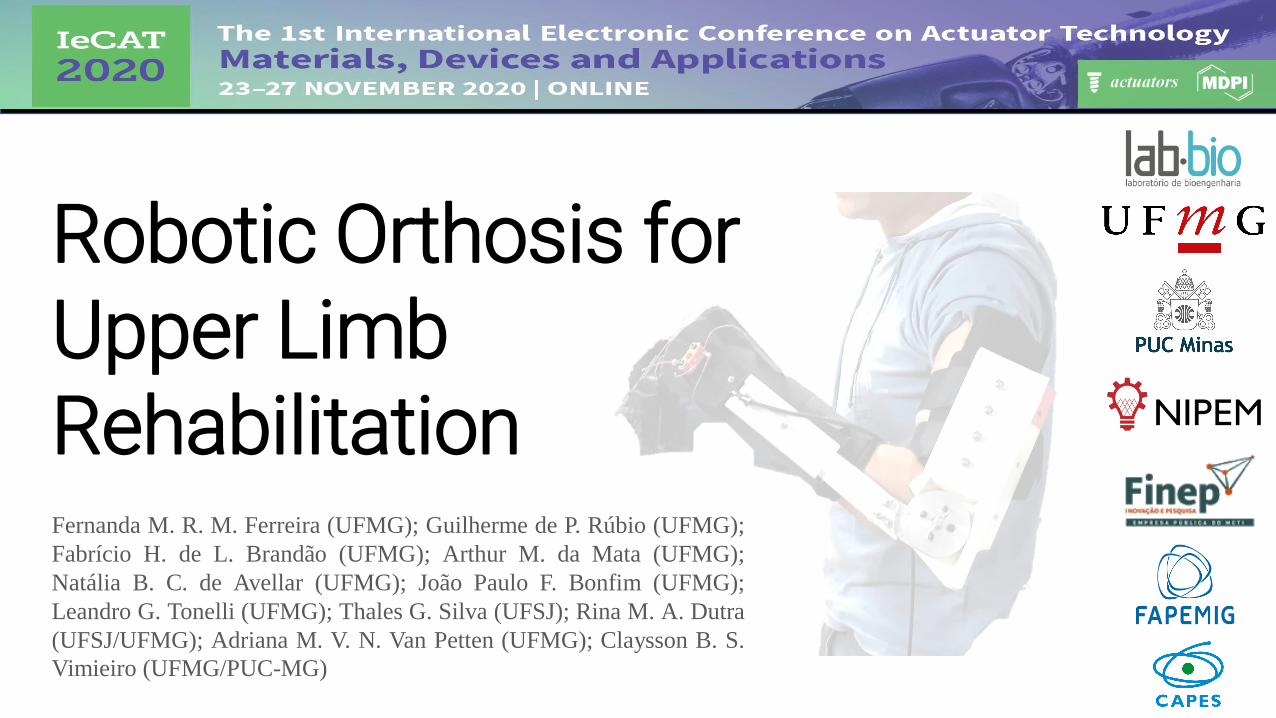
Robotic Orthosis for Upper Limb RehabilitationFernanda M. R. M. Ferreira (UFMG); Guilherme de P. Rúbio (UFMG);
Fabrício H. de L. Brandão (UFMG); Arthur M. da Mata (UFMG);
Natália B. C. de Avellar (UFMG); João Paulo F. Bonfim (UFMG);
Leandro G. Tonelli (UFMG); Thales G. Silva (UFSJ); Rina M. A. Dutra
(UFSJ/UFMG); Adriana M. V. N. Van Petten (UFMG); Claysson B. S.
Vimieiro (UFMG/PUC-MG)
SummaryIntroduction
Experiments
Results
Discussion
Conclusions
Acknowledgments
References

Introduction
Stroke - clinical syndrome
One of the main causes of death and disability
Upper extremity -70% of individuals
30 to 66% of patients do not have upper limb function on the affected side
5% to 20% demonstrate
complete functional recovery

Introduction
Robot-assisted therapy: training in dosage and much higher intensity
Improve the strategies of relearning motor and functional results
Disadvantages of robotic orthoses for
upper limb rehabilitation
High cost, material, and unfavorable
aesthetics
More effective rehabilitation
equipment

IntroductionWHAT IS THE AIM OF THIS STUDY?
Develop a robotic orthosis
Individuals with motor impairment of the upper limb resulting from a stroke
Help flexion and extension movements of the elbow and fingers
Validate the device in volunteers
Experiments
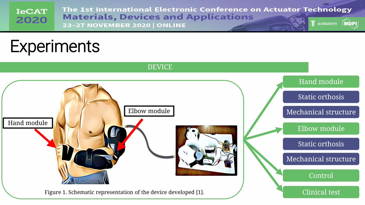
Figure 1. Schematic representation of the device developed [1].
Hand module
Elbow module
DEVICE
Static orthosis
Mechanical structure
Hand module
Elbow module
Static orthosis
Mechanical structure
Control
Clinical test

Experiments
Figure 2. Schematic mechanism representation of (a) closing and (b) opening fingers with artificial phalanx and tendons. Adapted from Rúbio et al. [2].
Artificial tendons
Artificial phalanges
HAND MODULE-MECHANICAL DESIGN
a b
Artificial metacarpal
Fingerstall
Kevlar multi-wire cables
Artificial tendons Artificial
phalanges

Experiments
Figure 2. Schematic mechanism representation of (a) closing and (b) opening fingers with artificial phalanx and tendons. Adapted from Rúbio et al. [2].
Artificial phalanges
HAND MODULE-MECHANICAL DESIGN
a b
Rigid Lactic Polyacid (PLA)
Artificial tendons Artificial
phalanges Artificial phalanges
Fingerstall
Figure 3. Artificial phalanx attached to the fingerstall [1].

Experiments
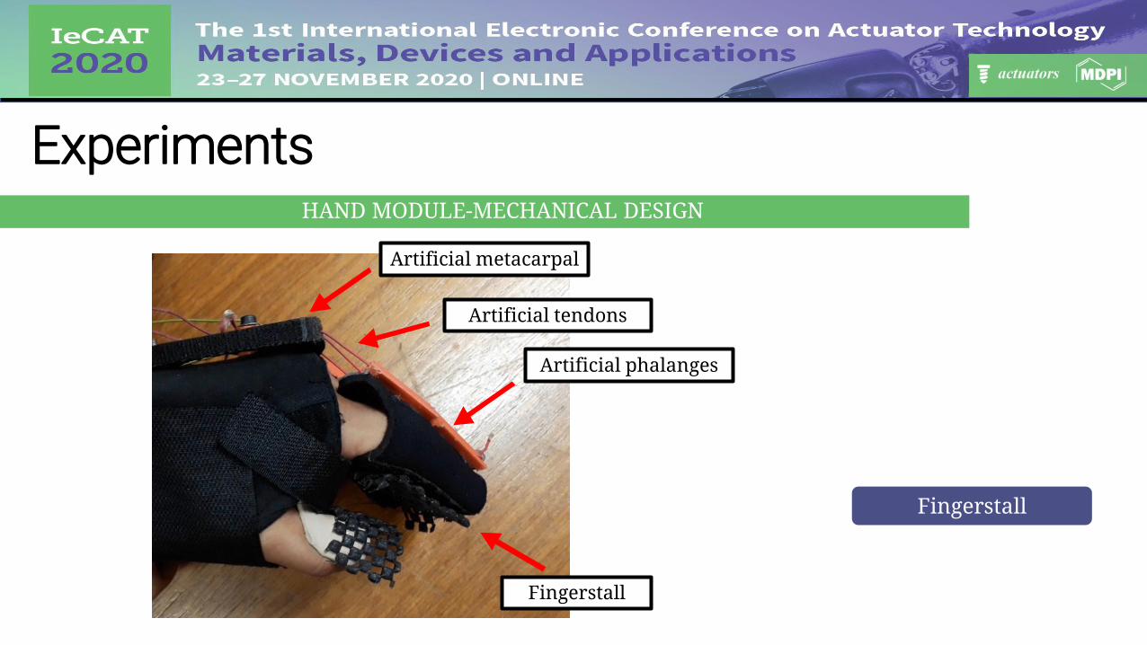
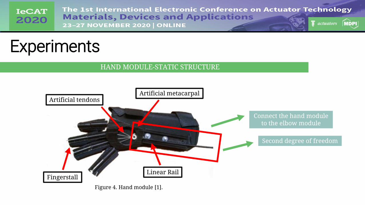
Figure 4. Hand module [1].
HAND MODULE-MECHANICAL DESIGN
Artificial metacarpal
Support and connection
FingerstallLinear Rail
Artificial tendonsArtificial metacarpal
ExperimentsHAND MODULE-MECHANICAL DESIGN
Fingerstall
Artificial metacarpal
Fingerstall
Artificial phalanges
Artificial tendons
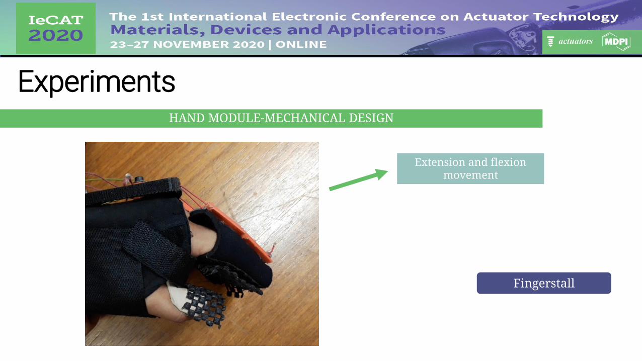
ExperimentsHAND MODULE-MECHANICAL DESIGN
Fingerstall
Extension and flexion movement
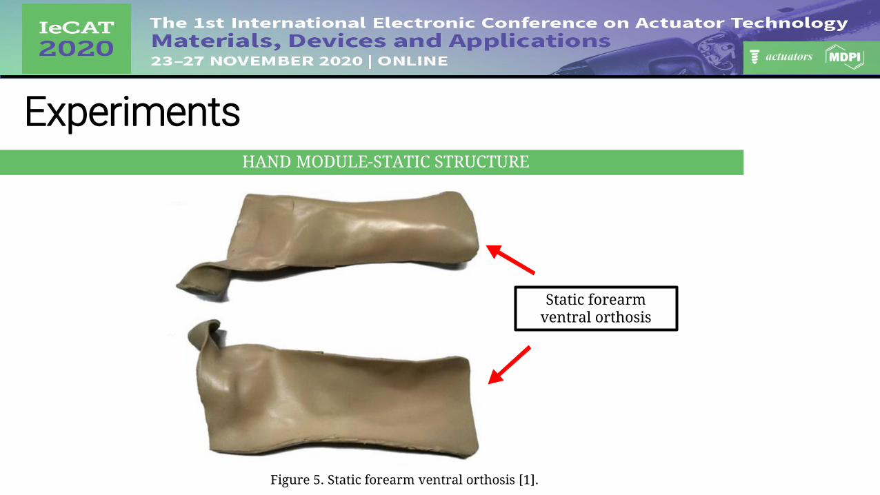
Static forearm ventral orthosis
ExperimentsHAND MODULE-STATIC STRUCTURE
/
Figure 5. Static forearm ventral orthosis [1].
ExperimentsHAND MODULE-STATIC STRUCTURE
FingerstallLinear Rail
Artificial tendonsArtificial metacarpal
Figure 4. Hand module [1].
Connect the hand module to the elbow module
Second degree of freedom
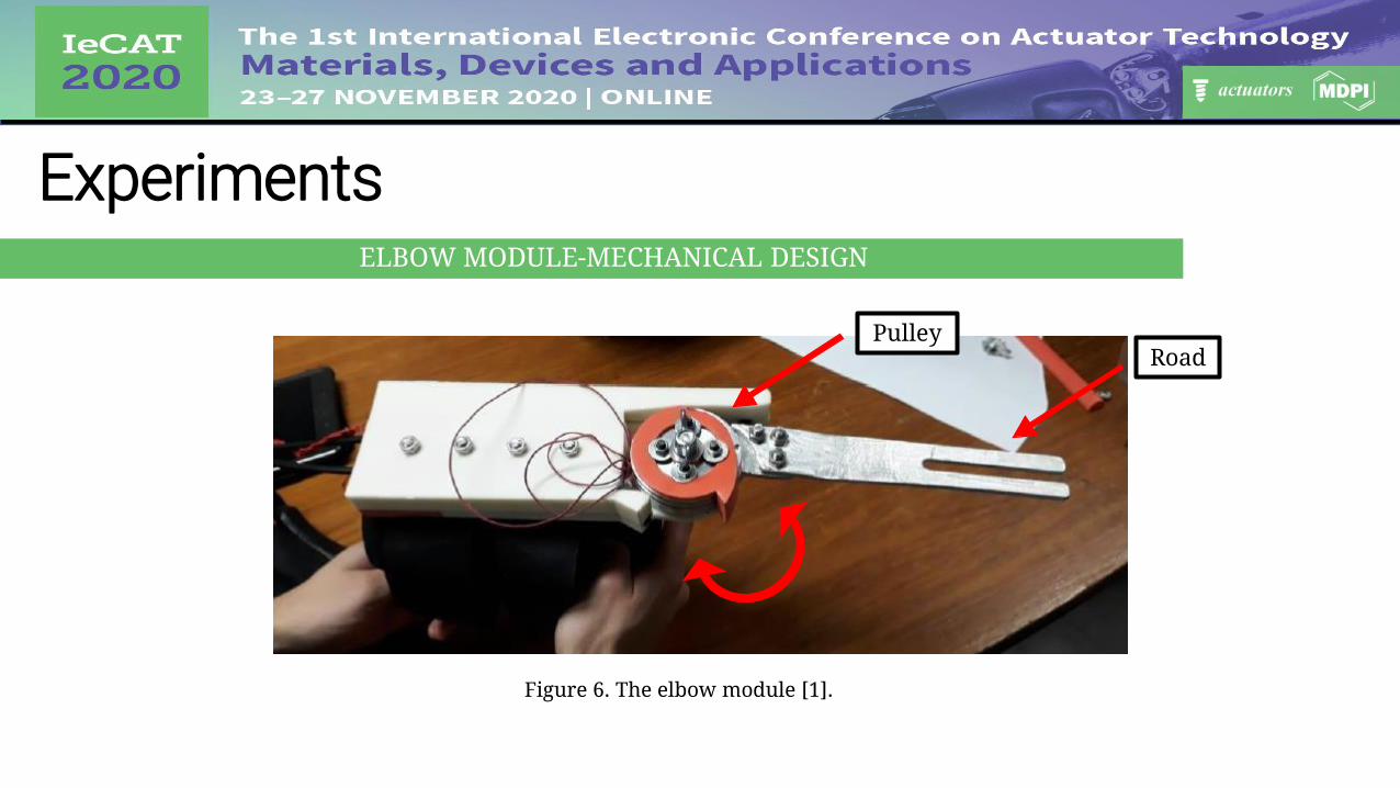
ExperimentsELBOW MODULE-MECHANICAL DESIGN
PulleyRoad
Figure 6. The elbow module [1].

ExperimentsELBOW MODULE-MECHANICAL DESIGN
Road
Figure 7. The elbow joint [1].

ExperimentsELBOW MODULE-MECHANICAL DESIGN
Conduits
Pulley base
Figure 7. The elbow joint [1].
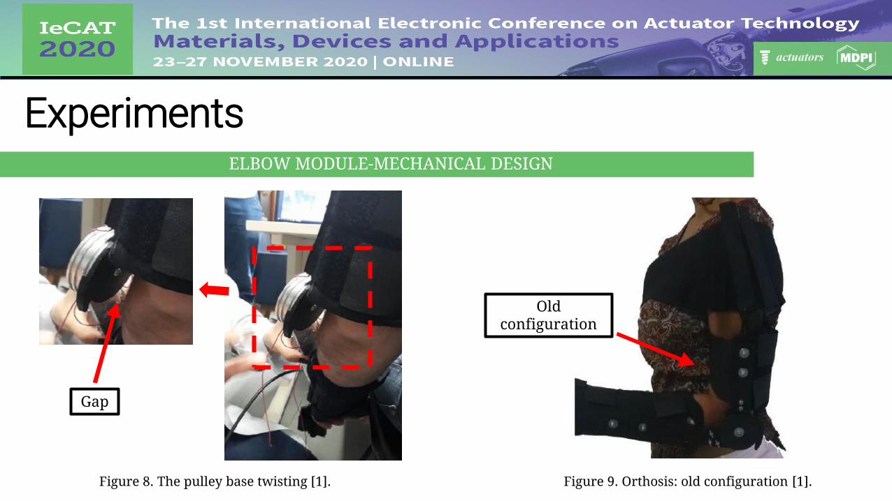
ExperimentsELBOW MODULE-MECHANICAL DESIGN
Gap
Old configuration
Figure 8. The pulley base twisting [1]. Figure 9. Orthosis: old configuration [1].

ExperimentsELBOW MODULE-MECHANICAL DESIGN
New configuration
Gap
Figure 10. Orthosis: new configuration [1].Figure 8. The pulley base twisting [1].
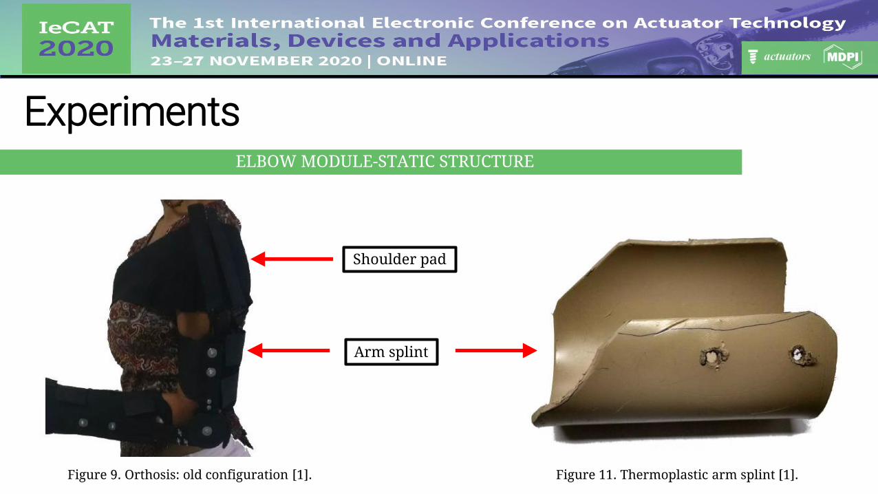
ExperimentsELBOW MODULE-STATIC STRUCTURE
Figure 11. Thermoplastic arm splint [1].Figure 9. Orthosis: old configuration [1].
Arm splint
Shoulder pad

ExperimentsELBOW MODULE-STATIC STRUCTURE
Figure 12. Shoulder pad [1].Figure 9. Orthosis: old configuration [1].
Arm splint
Shoulder pad

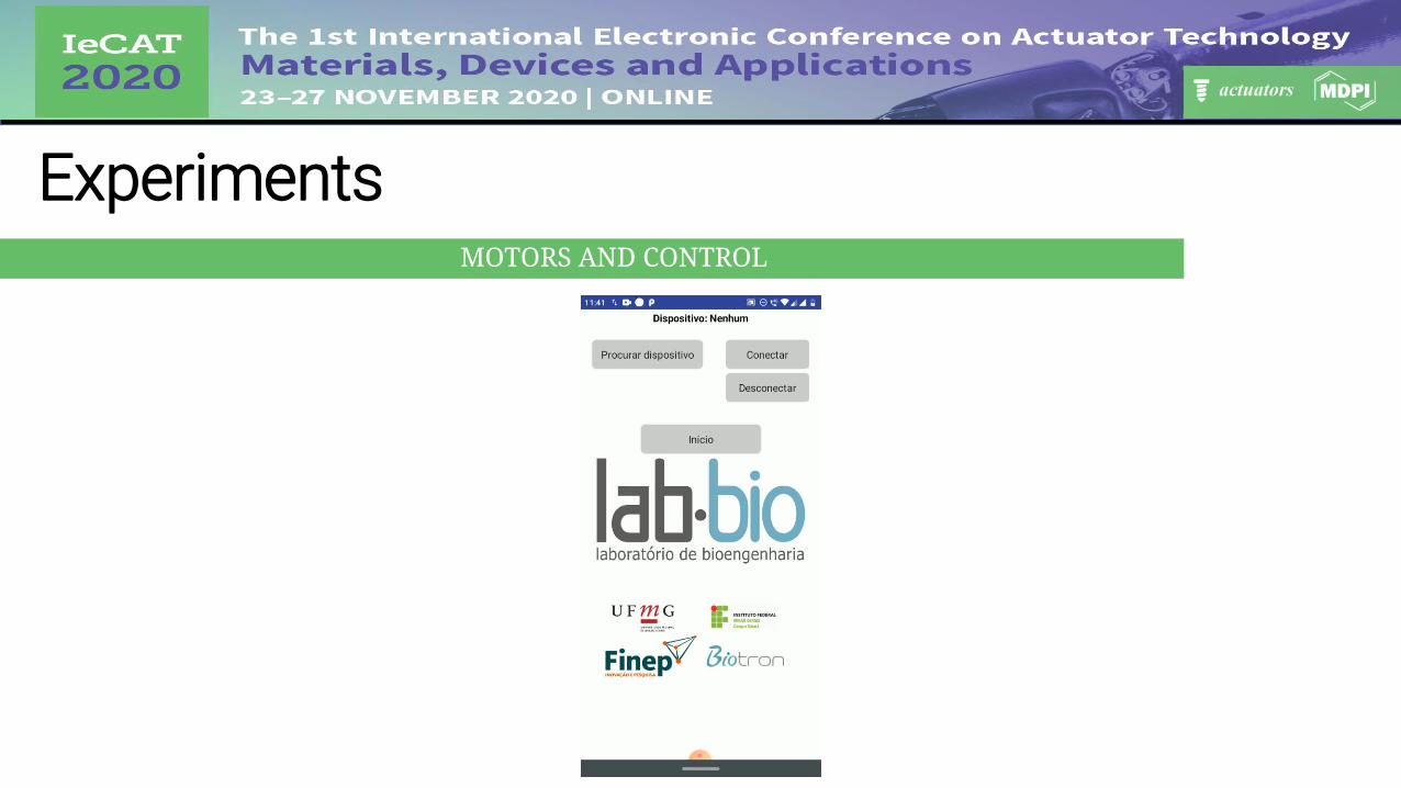
ExperimentsMOTORS AND CONTROL
Figure 13. motors and electronics responsible for the control [1].
DC motor
Servomotor
Reduction gearbox
Controller
Limit switches
DC Motor H bridge
f
f
d
e
e
d
c c
b
b
a
a

ExperimentsMOTORS AND CONTROL
To = P ⋅ Rg ⋅ sin θ
elbow joint angle
distance between the elbow joint center and center of gravity of the set
weight force
required torque to flex the elbow
ExperimentsMOTORS AND CONTROL

ExperimentsCLINICAL TEST
Participants Sex Age DominancePost stroke
time
Spasticity Level
Fingers Elbow
1 Male 73 Right 53 months 1 1
2 Male 38 Right 113 months 2 2
3 Female 25 Left 48 months 2 2
4 Female 48 Right 24 months 1 1+
Table 1. Participants characteristics
Volunteers Research Ethics Committee (COEP) - CAAE Registry: 22207213.5.0000.5149

ExperimentsCLINICAL TEST - PROCEDURES

ResultsHand opening tests Elbow movement tests

ResultsGrabbing a water bottle task Grabbing a ball task

Discussion
Perform the movements effectively
The fingers interfered with each other
The elbow module presented relative difficulty in performing
Figure 10. Orthosis: new configuration [1].
Old configuration
Figure 9. Orthosis: old configuration [1].
New configuration

Discussion
The excessive weight of the elbow module
Clinical test
Proper alignment between the exoskeleton and the user's anatomical joints

Conclusions
Correct biomechanical functioning
Prototype effectiveness and safety
Improve the mechanical structure of the orthosis
Long-term effect
References1. Personal file of the authors.
2. Rúbio, G. de P.; Ferreira, F.; de Lisboa Brandão, F.H.; Machado, V.; Tonelli, L.; Kozan, R.F.; Vimieiro, C. Design ofActuators Applied to a Upper Limb Orthosis. In Proceedings of the Proceedings of the 25th InternationalCongress of Mechanical Engineering; ABCM, 2019.

Acknowledgments

Contact information
Corresponding author: Fernanda Márcia Rodrigues Martins Ferreira (Ferreira, F.M.R.M)Graduate Program in Mechanical Engineering, Bioengineering LaboratoryUniversidade Federal de Minas Gerais, Belo Horizonte, Minas Gerais, Brazil.E-mail address: [email protected]: 33 07 66 89 12 57
TEAM