Robotic excavation in construction automation
10
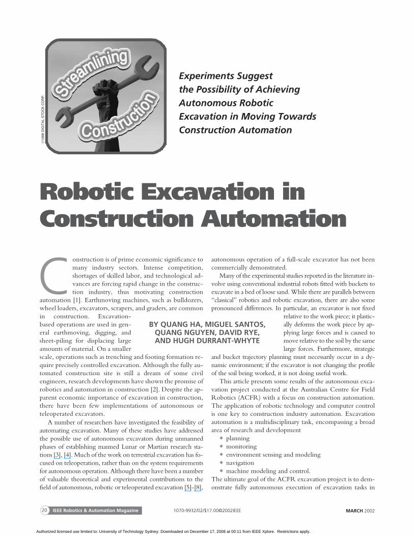
Experiments Suggest the Possibility of Achieving Autonomous Robotic Excavation in Moving Towards Construction Automation C onstruction is of prime economic significance to many industry sectors. Intense competition, shortages of skilled labor, and technological ad- vances are forcing rapid change in the construc- tion industry, thus motivating construction automation [1]. Earthmoving machines, such as bulldozers, wheel loaders, excavators, scrapers, and graders, are common in construction. Excavation- based operations are used in gen- eral earthmoving, digging, and sheet-piling for displacing large amounts of material. On a smaller scale, operations such as trenching and footing formation re- quire precisely controlled excavation. Although the fully au- tomated construction site is still a dream of some civil engineers, research developments have shown the promise of robotics and automation in construction [2]. Despite the ap- parent economic importance of excavation in construction, there have been few implementations of autonomous or teleoperated excavators. A number of researchers have investigated the feasibility of automating excavation. Many of these studies have addressed the possible use of autonomous excavators during unmanned phases of establishing manned Lunar or Martian research sta- tions [3], [4]. Much of the work on terrestrial excavation has fo- cused on teleoperation, rather than on the system requirements for autonomous operation. Although there have been a number of valuable theoretical and experimental contributions to the field of autonomous, robotic or teleoperated excavation [5]-[8], autonomous operation of a full-scale excavator has not been commercially demonstrated. Many of the experimental studies reported in the literature in- volve using conventional industrial robots fitted with buckets to excavate in a bed of loose sand. While there are parallels between “classical” robotics and robotic excavation, there are also some pronounced differences. In particular, an excavator is not fixed relative to the work piece; it plastic- ally deforms the work piece by ap- plying large forces and is caused to move relative to the soil by the same large forces. Furthermore, strategic and bucket trajectory planning must necessarily occur in a dy- namic environment; if the excavator is not changing the profile of the soil being worked, it is not doing useful work. This article presents some results of the autonomous exca- vation project conducted at the Australian Centre for Field Robotics (ACFR) with a focus on construction automation. The application of robotic technology and computer control is one key to construction industry automation. Excavation automation is a multidisciplinary task, encompassing a broad area of research and development ◆ planning ◆ monitoring ◆ environment sensing and modeling ◆ navigation ◆ machine modeling and control. The ultimate goal of the ACFR excavation project is to dem- onstrate fully autonomous execution of excavation tasks in MARCH 2002 IEEE Robotics & Automation Magazine 20 BY QUANG HA, MIGUEL SANTOS, QUANG NGUYEN, DAVID RYE, AND HUGH DURRANT-WHYTE Robotic Excavation in Construction Automation 1998 DIGITAL STOCK CORP. 1070-9932/02/$17.00©2002IEEE Authorized licensed use limited to: University of Technology Sydney. Downloaded on December 17, 2008 at 00:11 from IEEE Xplore. Restrictions apply.
-
Upload
independent -
Category
Documents
-
view
2 -
download
0
Transcript of Robotic excavation in construction automation
Experiments Suggestthe Possibility of AchievingAutonomous RoboticExcavation in Moving TowardsConstruction Automation
Construction is of prime economic significance tomany industry sectors. Intense competition,shortages of skilled labor, and technological ad-vances are forcing rapid change in the construc-tion industry, thus motivating construction
automation [1]. Earthmoving machines, such as bulldozers,wheel loaders, excavators, scrapers, and graders, are commonin construction. Excavation-based operations are used in gen-eral earthmoving, digging, andsheet-piling for displacing largeamounts of material. On a smallerscale, operations such as trenching and footing formation re-quire precisely controlled excavation. Although the fully au-tomated construction site is still a dream of some civilengineers, research developments have shown the promise ofrobotics and automation in construction [2]. Despite the ap-parent economic importance of excavation in construction,there have been few implementations of autonomous orteleoperated excavators.
A number of researchers have investigated the feasibility ofautomating excavation. Many of these studies have addressedthe possible use of autonomous excavators during unmannedphases of establishing manned Lunar or Martian research sta-tions [3], [4]. Much of the work on terrestrial excavation has fo-cused on teleoperation, rather than on the system requirementsfor autonomous operation. Although there have been a numberof valuable theoretical and experimental contributions to thefield of autonomous, robotic or teleoperated excavation [5]-[8],
autonomous operation of a full-scale excavator has not beencommercially demonstrated.
Many of the experimental studies reported in the literature in-volve using conventional industrial robots fitted with buckets toexcavate in a bed of loose sand. While there are parallels between“classical” robotics and robotic excavation, there are also somepronounced differences. In particular, an excavator is not fixed
relative to the work piece; it plastic-ally deforms the work piece by ap-plying large forces and is caused tomove relative to the soil by the samelarge forces. Furthermore, strategic
and bucket trajectory planning must necessarily occur in a dy-namic environment; if the excavator is not changing the profileof the soil being worked, it is not doing useful work.
This article presents some results of the autonomous exca-vation project conducted at the Australian Centre for FieldRobotics (ACFR) with a focus on construction automation.The application of robotic technology and computer controlis one key to construction industry automation. Excavationautomation is a multidisciplinary task, encompassing a broadarea of research and development
� planning� monitoring� environment sensing and modeling� navigation� machine modeling and control.
The ultimate goal of the ACFR excavation project is to dem-onstrate fully autonomous execution of excavation tasks in
MARCH 2002IEEE Robotics & Automation Magazine20
BY QUANG HA, MIGUEL SANTOS,QUANG NGUYEN, DAVID RYE,AND HUGH DURRANT-WHYTE
Robotic Excavation inConstruction Automation
19
98D
IGIT
AL
ST
OC
KC
OR
P.
1070-9932/02/$17.00©2002IEEE
Authorized licensed use limited to: University of Technology Sydney. Downloaded on December 17, 2008 at 00:11 from IEEE Xplore. Restrictions apply.
common construction, such as loading a truck or digging atrench. A number of difficult theoretical and practical prob-lems must be solved to achieve this objective. The problemsfall into three main groups: excavation planning, sensing andestimation, and control.
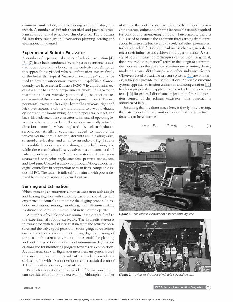
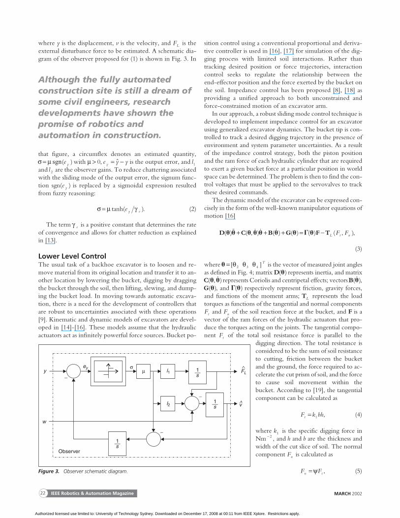
Experimental Robotic ExcavatorA number of experimental studies of robotic excavation [4],[6], [7] have been conducted by using a conventional indus-trial robot fitted with a bucket as the end-effector. Althoughthis approach has yielded valuable information, we are firmlyof the belief that typical “excavator technology” should beused to develop autonomous excavation capabilities. Conse-quently, we have used a Komatsu PC05-7 hydraulic mini-ex-cavator as the basis for our experimental work. This 1.5-tonnemachine has been extensively modified [9] to meet the re-quirements of the research and development project. The ex-perimental excavator has eight hydraulic actuators: right andleft travel motors, a cab slew motor, and two-way hydrauliccylinders on the boom swing, boom, dipper arm, bucket, andback-fill blade axes. The excavator cabin and all operating le-vers have been removed and the original manually actuateddirection control valves replaced by electrohydraulicservovalves. Ancillary equipment added to support theservovalves includes an accumulator with an unloading valve,solenoid check valves, and an oil-to-air radiator. Fig. 1 showsthe modified robotic excavator during a trench-forming task,while the electrohydraulic servovalves, accumulator, and oilradiator can be seen in Fig. 2. The excavator is extensively in-strumented with joint angle encoders, pressure transducers,and load pins. Control is achieved through Moog proprietarydigital controllers in conjunction with an IBM-compatible in-dustrial PC. The system is fully self-contained, with power de-rived from the excavator’s electrical system.
Sensing and EstimationWhen operating an excavator, a human uses senses such as sightand hearing together with reasoning based on knowledge andexperience to control and monitor the digging process. In ro-botic excavation, sensing, modeling, and decision-makinghardware and software must be used in lieu of the operator.
A number of vehicle and environment sensors are fitted tothe experimental robotic excavator. The hydraulic system isinstrumented with transducers that measure the actuator pres-sures and the valve spool positions. Strain-gauge force sensorsenable direct force measurement during digging. Sensing ofthe machine’s external environment is essential for planningand controlling platform motion and autonomous digging op-erations and for monitoring progress towards task completion.A commercial time-of-flight laser measurement system is usedto scan the terrain on either side of the bucket, providing asurface profile with 10-mm resolution and a statistical error of± 15 mm within a sensing range of 1-8 m.
Parameter estimation and system identification is an impor-tant consideration in robotic excavation. Although a number
of states in the control state space are directly measured by ma-chine sensors, estimation of some inaccessible states is requiredfor control and monitoring purposes. Furthermore, there isalso a need to estimate the uncertain forces arising from inter-action between the bucket and the soil, and other external dis-turbances such as friction and load inertia changes, in order toreject their influence and achieve robust performance. A vari-ety of robust estimation techniques can be used. In general,the term “robust estimation” refers to the design of determin-istic observers in the presence of system uncertainties, delays,modeling errors, disturbances, and other unknown factors.Observers based on variable structure systems [10] are of inter-est, as they can provide robust estimations. A variable structuresystems approach to friction estimation and compensation [11]has been proposed and applied to electrohydraulic servo sys-tems [12] for external disturbance rejection in force and posi-tion control of the robotic excavator. This approach issummarized here.
Assuming that the disturbance force is slowly time-varying,the state model for 1-D motion occasioned by an actuatorforce w can be written as
& , & , &v w F F y vL L= − = =0 , (1)
MARCH 2002 IEEE Robotics & Automation Magazine 21
Figure 1. The robotic excavator in a trench-forming task.
Figure 2. A view of the electrohydraulic servovalve stack.
Authorized licensed use limited to: University of Technology Sydney. Downloaded on December 17, 2008 at 00:11 from IEEE Xplore. Restrictions apply.
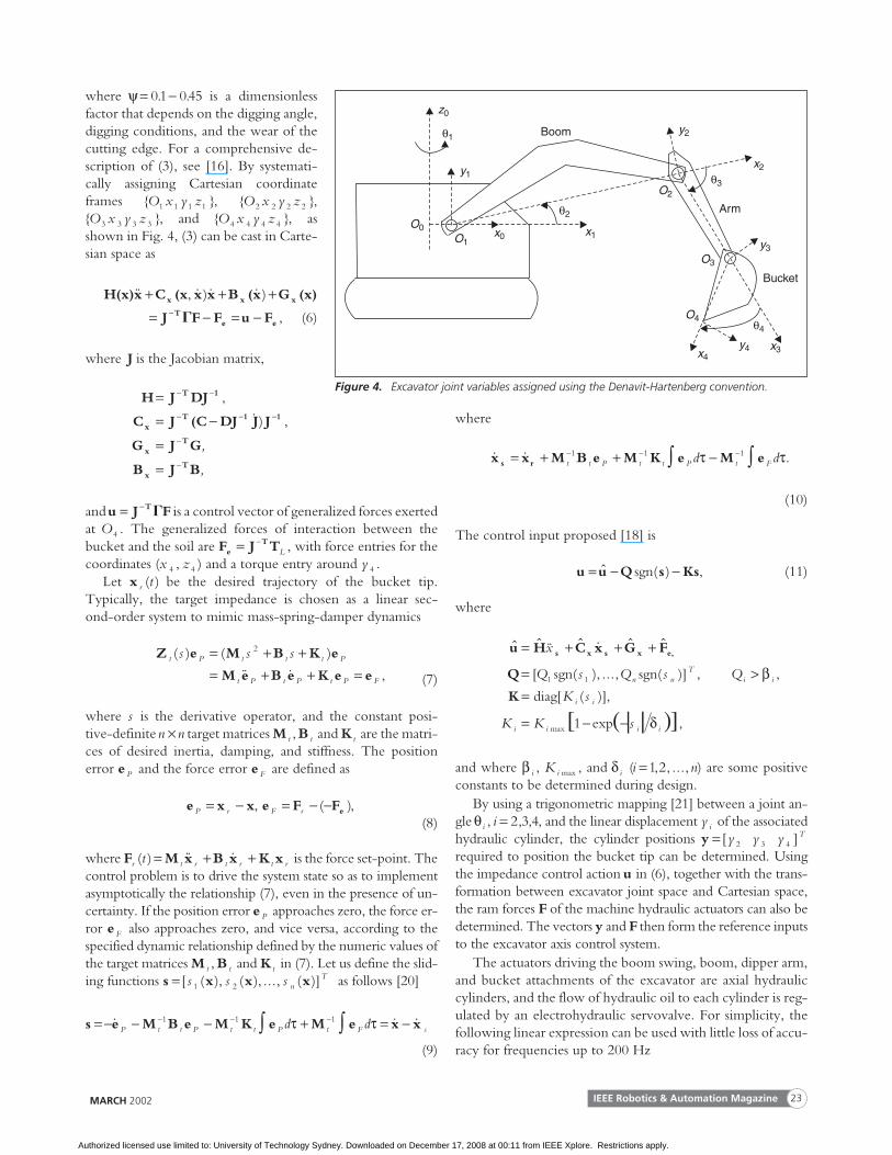
where y is the displacement, v is the velocity, and FL is theexternal disturbance force to be estimated. A schematic dia-gram of the observer proposed for (1) is shown in Fig. 3. In
that figure, a circumflex denotes an estimated quantity,σ µ= sgn( )e y with µ > 0, e y yy = −$ is the output error, and l1and l 2 are the observer gains. To reduce chattering associatedwith the sliding mode of the output error, the signum func-tion sgn( )e y is replaced by a sigmoidal expression resultedfrom fuzzy reasoning:
σ µ γ= tanh( )e y e . (2)
The term γ e is a positive constant that determines the rateof convergence and allows for chatter reduction as explainedin [13].
Lower Level ControlThe usual task of a backhoe excavator is to loosen and re-move material from its original location and transfer it to an-other location by lowering the bucket, digging by draggingthe bucket through the soil, then lifting, slewing, and dump-ing the bucket load. In moving towards automatic excava-tion, there is a need for the development of controllers thatare robust to uncertainties associated with these operations[9]. Kinematic and dynamic models of excavators are devel-oped in [14]-[16]. These models assume that the hydraulicactuators act as infinitely powerful force sources. Bucket po-
sition control using a conventional proportional and deriva-tive controller is used in [16], [17] for simulation of the dig-ging process with limited soil interactions. Rather thantracking desired position or force trajectories, interactioncontrol seeks to regulate the relationship between theend-effector position and the force exerted by the bucket onthe soil. Impedance control has been proposed [8], [18] asproviding a unified approach to both unconstrained andforce-constrained motion of an excavator arm.
In our approach, a robust sliding mode control technique isdeveloped to implement impedance control for an excavatorusing generalized excavator dynamics. The bucket tip is con-trolled to track a desired digging trajectory in the presence ofenvironment and system parameter uncertainties. As a resultof the impedance control strategy, both the piston positionand the ram force of each hydraulic cylinder that are requiredto exert a given bucket force at a particular position in worldspace can be determined. The problem is then to find the con-trol voltages that must be applied to the servovalves to trackthese desired commands.
The dynamic model of the excavator can be expressed con-cisely in the form of the well-known manipulator equations ofmotion [16]
D C B G F T( )&& ( , & )& ( & ) ( ) ( ) ( , )� � � � � � � � �+ + + = − L t nF F ,
(3)
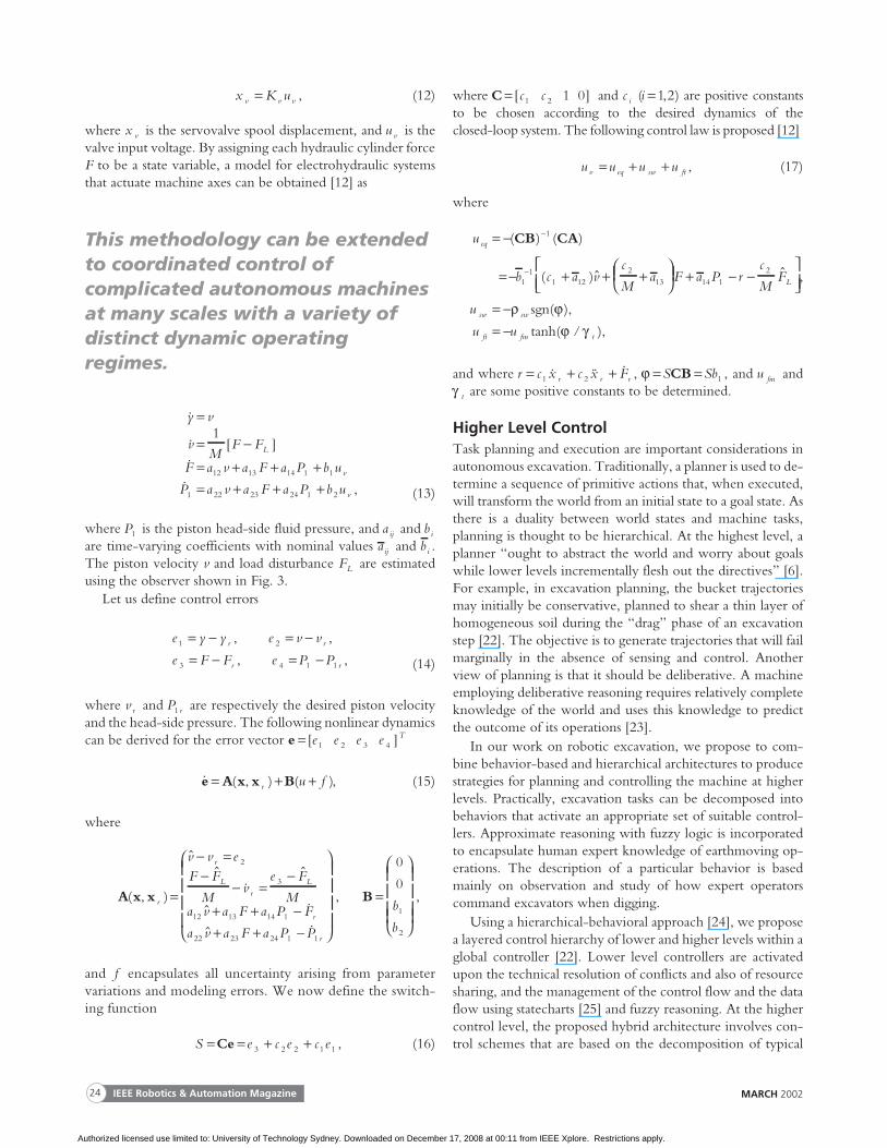
where � = [ ]θ θ θ2 3 4T is the vector of measured joint angles
as defined in Fig. 4; matrix D( )� represents inertia, and matrixC( , & )� � represents Coriolis and centripetal effects; vectorsB( & )� ,G( )� , and � �( ) respectively represent friction, gravity forces,and functions of the moment arms; TL represents the loadtorques as functions of the tangential and normal componentsFt and Fn of the soil reaction force at the bucket, and F is avector of the ram forces of the hydraulic actuators that pro-duce the torques acting on the joints. The tangential compo-nent Ft of the total soil resistance force is parallel to the
digging direction. The total resistance isconsidered to be the sum of soil resistanceto cutting, friction between the bucketand the ground, the force required to ac-celerate the cut prism of soil, and the forceto cause soil movement within thebucket. According to [19], the tangentialcomponent can be calculated as
F k bht = 1 , (4)
where k1 is the specific digging force inNm 2− , and h and b are the thickness andwidth of the cut slice of soil. The normalcomponent Fn is calculated as
F Fn t= ψ , (5)
IEEE Robotics & Automation Magazine22 MARCH 2002
y
w
−
eyl1
l2
Observer
FL
v̂
σµ
−
1s
−1s
1s
∧
Figure 3. Observer schematic diagram.
Although the fully automatedconstruction site is still a dream ofsome civil engineers, researchdevelopments have shown thepromise of robotics andautomation in construction.
Authorized licensed use limited to: University of Technology Sydney. Downloaded on December 17, 2008 at 00:11 from IEEE Xplore. Restrictions apply.
where ψ = −01 045. . is a dimensionlessfactor that depends on the digging angle,digging conditions, and the wear of thecutting edge. For a comprehensive de-scription of (3), see [16]. By systemati-cally assigning Cartesian coordinateframes { }O x y z1 1 1 1 , { }O x y z2 2 2 2 ,{ }O x y z3 3 3 3 , and { }O x y z4 4 4 4 , asshown in Fig. 4, (3) can be cast in Carte-sian space as
H(x)x C (x x x B (x G (x)x x x&& , & )& & )+ + += − = −−J F F u FT
e e� , (6)
where J is the Jacobian matrix,
H J DJ
C J (C DJ J J
G J G
B J B
T 1
xT 1 1
xT
xT
=
= −
=
=
− −
− − −
−
−
,
& ) ,
,
,
andu J FT= − � is a control vector of generalized forces exertedat O4 . The generalized forces of interaction between thebucket and the soil are F J Te
T= −L , with force entries for the
coordinates (x z4 4, ) and a torque entry around y 4 .Let x r t( ) be the desired trajectory of the bucket tip.
Typically, the target impedance is chosen as a linear sec-ond-order system to mimic mass-spring-damper dynamics
Z e M B K e
M e B e K e et P t t t P
t P t P t P F
s s s( ) ( )
&& & ,
= + += + + =
2
(7)
where s is the derivative operator, and the constant posi-tive-definiten n× target matrices M t ,B t and K t are the matri-ces of desired inertia, damping, and stiffness. The positionerror e P and the force error e F are defined as
e x xP r= − , e F FeF r= − −( ),(8)
where F M x B x K xr t r t r t rt( ) && &= + + is the force set-point. Thecontrol problem is to drive the system state so as to implementasymptotically the relationship (7), even in the presence of un-certainty. If the position error e P approaches zero, the force er-ror e F also approaches zero, and vice versa, according to thespecified dynamic relationship defined by the numeric values ofthe target matrices M t ,B t and K t in (7). Let us define the slid-ing functions s x x x= [ ( ), ( ), ..., ( )]s s s n
T1 2 as follows [20]
s e M B e M K e M e x x= − − − + = −− − −∫ ∫& & &P t t P t t P t F sd d1 1 1τ τ
(9)
where
& &x x M B e M K e M es r= + + −− − −∫ ∫t t P t t P t Fd d1 1 1τ τ.
(10)
The control input proposed [18] is
u u Q s Ks= − −$ ( )sgn , (11)
where
$ $ && $ & $ $
[ ( ), ..., (
u H C x G F
Q
s x s x e,= + + +
=
x
Q s Q sn n1 1sgn sgn
( )[ ]
)] , ,
[ ( )],
exp ,max
Ti i
i i
i i i i
Q
K s
K K s
>=
= − −
β
δ
K diag
1
and where β i , K i max , and δ i (i n=1 2, , ..., ) are some positiveconstants to be determined during design.
By using a trigonometric mapping [21] between a joint an-gle θ i , i = 2 3 4, , , and the linear displacement y i of the associatedhydraulic cylinder, the cylinder positions y = [ ]y y y T
2 3 4
required to position the bucket tip can be determined. Usingthe impedance control action u in (6), together with the trans-formation between excavator joint space and Cartesian space,the ram forces F of the machine hydraulic actuators can also bedetermined. The vectors y and F then form the reference inputsto the excavator axis control system.
The actuators driving the boom swing, boom, dipper arm,and bucket attachments of the excavator are axial hydrauliccylinders, and the flow of hydraulic oil to each cylinder is reg-ulated by an electrohydraulic servovalve. For simplicity, thefollowing linear expression can be used with little loss of accu-racy for frequencies up to 200 Hz
IEEE Robotics & Automation Magazine 23MARCH 2002
z0
O0O1
x0 x1
x4y4 x3
O4
O3
y3
Bucket
O2
y2
x2
Boom
y1
Arm
θ1
θ2
θ3
θ4
Figure 4. Excavator joint variables assigned using the Denavit-Hartenberg convention.
Authorized licensed use limited to: University of Technology Sydney. Downloaded on December 17, 2008 at 00:11 from IEEE Xplore. Restrictions apply.
x K uv v v= , (12)
where x v is the servovalve spool displacement, and u v is thevalve input voltage. By assigning each hydraulic cylinder forceF to be a state variable, a model for electrohydraulic systemsthat actuate machine axes can be obtained [12] as
&
& [ ]
&
&
y v
vM
F F
F a v a F a P b u
P a v a
L
v
=
= −= + + += +
1
12 13 14 1 1
1 22 23 F a P b u v+ +24 1 2 , (13)
where P1 is the piston head-side fluid pressure, and a ij and bi
are time-varying coefficients with nominal values aij and bi .The piston velocity v and load disturbance FL are estimatedusing the observer shown in Fig. 3.
Let us define control errors
e y y e v v
e F F e P Pr r
r r
1 2
3 4 1 1
= − = −= − = −
, ,
, , (14)
where v r and P r1 are respectively the desired piston velocityand the head-side pressure. The following nonlinear dynamicscan be derived for the error vector e = [ ]e e e e T
1 2 3 4
& ( , ) ( )e A x x B= + +r u f , (15)
where
A x x( , )
$$
&$
$r
r
Lr
L
v v eF F
Mv
e F
Ma v a F a P
=
− =−
− =−
+ +
2
3
12 13 14 1 −+ + −
&
$ &
F
a v a F a P Pr
r22 23 24 1 1
, B =
0
0
1
2
b
b
,
and f encapsulates all uncertainty arising from parametervariations and modeling errors. We now define the switch-ing function
S e c e c e= = + +Ce 3 2 2 1 1 , (16)
where C = [ ]c c1 2 1 0 and c i (i =1 2, ) are positive constantsto be chosen according to the desired dynamics of theclosed-loop system. The following control law is proposed [12]
u u u uv eq sw ft= + + , (17)
where
u
b c a vc
Ma F a
eq = −
= − + + +
+
−
−
( ) ( )
( )$
CB CA1
11
1 122
13 14P rc
MF
u
u u
L
sw sw
ft fm t
12− −
= −= −
$ ,
( ),
( /
ρ ϕϕ γ
sgn
tanh ),
and where r c x c x Fr r r= + +1 2& && & , ϕ = =S SbCB 1 , and u fm andγ t are some positive constants to be determined.
Higher Level ControlTask planning and execution are important considerations inautonomous excavation. Traditionally, a planner is used to de-termine a sequence of primitive actions that, when executed,will transform the world from an initial state to a goal state. Asthere is a duality between world states and machine tasks,planning is thought to be hierarchical. At the highest level, aplanner “ought to abstract the world and worry about goalswhile lower levels incrementally flesh out the directives” [6].For example, in excavation planning, the bucket trajectoriesmay initially be conservative, planned to shear a thin layer ofhomogeneous soil during the “drag” phase of an excavationstep [22]. The objective is to generate trajectories that will failmarginally in the absence of sensing and control. Anotherview of planning is that it should be deliberative. A machineemploying deliberative reasoning requires relatively completeknowledge of the world and uses this knowledge to predictthe outcome of its operations [23].
In our work on robotic excavation, we propose to com-bine behavior-based and hierarchical architectures to producestrategies for planning and controlling the machine at higherlevels. Practically, excavation tasks can be decomposed intobehaviors that activate an appropriate set of suitable control-lers. Approximate reasoning with fuzzy logic is incorporatedto encapsulate human expert knowledge of earthmoving op-erations. The description of a particular behavior is basedmainly on observation and study of how expert operatorscommand excavators when digging.
Using a hierarchical-behavioral approach [24], we proposea layered control hierarchy of lower and higher levels within aglobal controller [22]. Lower level controllers are activatedupon the technical resolution of conflicts and also of resourcesharing, and the management of the control flow and the dataflow using statecharts [25] and fuzzy reasoning. At the highercontrol level, the proposed hybrid architecture involves con-trol schemes that are based on the decomposition of typical
IEEE Robotics & Automation Magazine24 MARCH 2002
This methodology can be extendedto coordinated control ofcomplicated autonomous machinesat many scales with a variety ofdistinct dynamic operatingregimes.
Authorized licensed use limited to: University of Technology Sydney. Downloaded on December 17, 2008 at 00:11 from IEEE Xplore. Restrictions apply.
excavation tasks into states or state elements. Each task is rep-resented by a state in a statechart. At the lowest level in thestatechart hierarchy are state elements to be used for the con-trol of machine axes.
Unlike finite-state machines [26], statecharts allow forcomponent reuse, concurrency, and for complex nested states(superstates), if required. A statechart is used to represent astate machine consisting of states and transitions between statestogether with synchronization states and pseudostates [25].Every state object has entry and exit actions and executes theparticular behavior or activity until a transition is set and thestate is exited [22]. Transition conditions can be refined tohave event priorities if more than one condition is true at thesame time or can be seen as if/else or switch/case structures.For transition between state elements, a characteristic functionγ i associated with the state S i is defined here as follows
γ i
i jS S
i= , ,..=
1
0 1 2
,
,
transition from to
is active,S i .,r . (18)
A task element base, { , , , .., }τ i i r=1 2 , can contain one ormore feasible elemental operations of the machine actuators[22]: perhapsτ 1 —adjust the engine throttle to maintain a con-stant speed, τ 2 —maintain the current position for a certaintime, τ 3 —curl the bucket inward, and τ 4 —curl the bucketoutward, and so on.
To illustrate this control architecture, consider the tasks ofloading and of digging a trench to a certain depth. In loading,one pass in the task of removing soil from a pile can be decom-posed as consisting of the states of positioning the bucket witha specified attack angle, penetrating the soil by curling thebucket inward, lifting and swinging the boom, and thendumping soil by curling the bucket outward.
Trenching, another common construction task, can be de-composed to the following sequence of states within a statechart:
1) Position the bucket over the trench start.2) Lower the boom to the ground surface.3) Penetrate the ground by curling the bucket.4) Drag the bucket teeth in a straight line by moving the
arm and the boom simultaneously.5) Curl the bucket to collect soil into the bucket.6) Raise the boom out of contact with ground.7) Dump the bucket contents at the side of the trench.8) Check the necessity of doing another dig cycle according
to the specified trench dimensions. If necessary, repeat steps1-8, or else terminate the task.
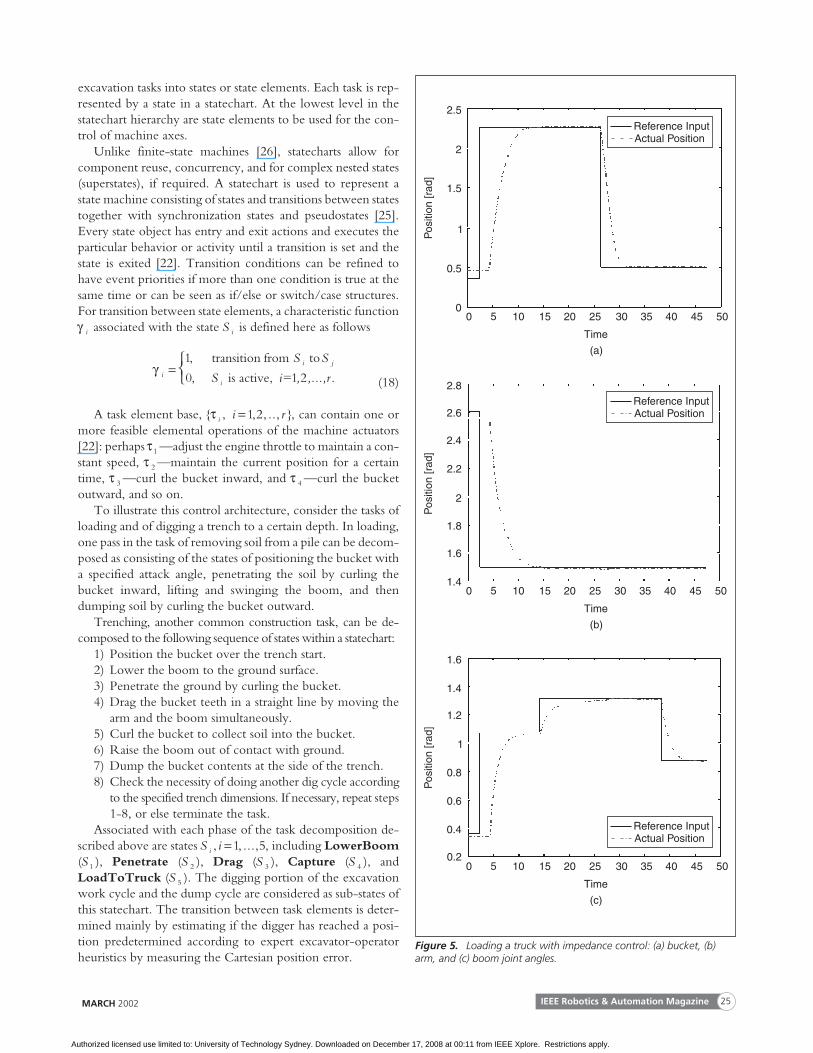
Associated with each phase of the task decomposition de-scribed above are states S ii , , ...,=1 5, including LowerBoom(S 1 ), Penetrate (S 2 ), Drag (S 3 ), Capture (S 4 ), andLoadToTruck (S 5 ). The digging portion of the excavationwork cycle and the dump cycle are considered as sub-states ofthis statechart. The transition between task elements is deter-mined mainly by estimating if the digger has reached a posi-tion predetermined according to expert excavator-operatorheuristics by measuring the Cartesian position error.
MARCH 2002 IEEE Robotics & Automation Magazine 25
Pos
ition
[rad
]
2.5
2
1.5
1
0.5
00 5 10 15 20 25 30 35 40 45 50
Time
(a)
Reference InputActual Position
Reference InputActual Position
Reference InputActual Position
Pos
ition
[rad
]
2.8
2.6
2.4
2.2
2
1.8
0 5 10 15 20 25 30 35 40 45 50
Time
(b)
Pos
ition
[rad
]
1.6
1.4
1.2
1
0.8
0.6
0 5 10 15 20 25 30 35 40 45 50
Time
(c)
1.6
1.4
0.4
0.2
Figure 5. Loading a truck with impedance control: (a) bucket, (b)arm, and (c) boom joint angles.
Authorized licensed use limited to: University of Technology Sydney. Downloaded on December 17, 2008 at 00:11 from IEEE Xplore. Restrictions apply.
Experimental ResultsExperiments have been performed using the robotic excavatorshown in Fig. 1. Data acquisition and control algorithms arewritten in C++ and executed under the Windows NT operat-ing system. The sampling time is chosen to be 0.010 s, anddata is communicated between the five control system proces-sors by message-passing over a controller area network (CAN)bus at 250 kb/s. Some typical excavation tasks in constructionautomation can be demonstrated with our robotic machine.
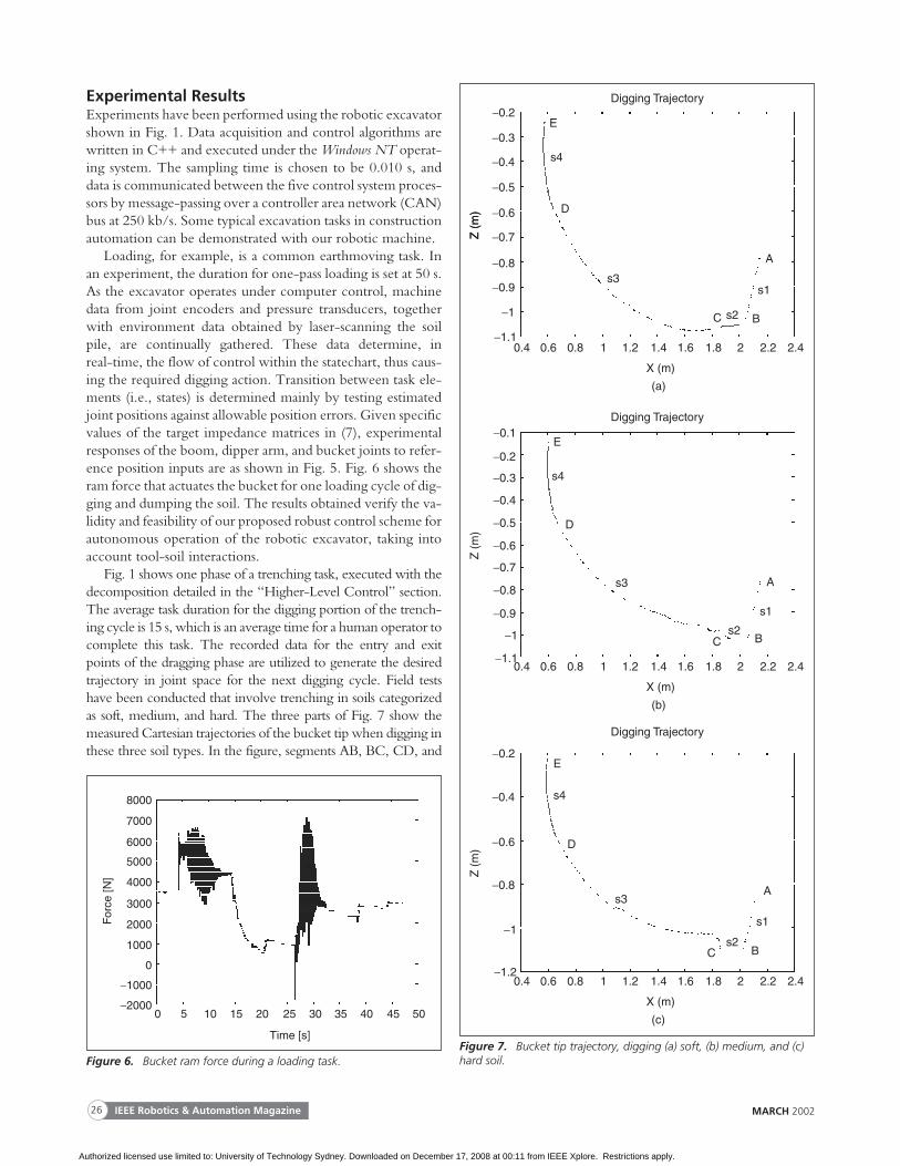
Loading, for example, is a common earthmoving task. Inan experiment, the duration for one-pass loading is set at 50 s.As the excavator operates under computer control, machinedata from joint encoders and pressure transducers, togetherwith environment data obtained by laser-scanning the soilpile, are continually gathered. These data determine, inreal-time, the flow of control within the statechart, thus caus-ing the required digging action. Transition between task ele-ments (i.e., states) is determined mainly by testing estimatedjoint positions against allowable position errors. Given specificvalues of the target impedance matrices in (7), experimentalresponses of the boom, dipper arm, and bucket joints to refer-ence position inputs are as shown in Fig. 5. Fig. 6 shows theram force that actuates the bucket for one loading cycle of dig-ging and dumping the soil. The results obtained verify the va-lidity and feasibility of our proposed robust control scheme forautonomous operation of the robotic excavator, taking intoaccount tool-soil interactions.
Fig. 1 shows one phase of a trenching task, executed with thedecomposition detailed in the “Higher-Level Control” section.The average task duration for the digging portion of the trench-ing cycle is 15 s, which is an average time for a human operator tocomplete this task. The recorded data for the entry and exitpoints of the dragging phase are utilized to generate the desiredtrajectory in joint space for the next digging cycle. Field testshave been conducted that involve trenching in soils categorizedas soft, medium, and hard. The three parts of Fig. 7 show themeasured Cartesian trajectories of the bucket tip when digging inthese three soil types. In the figure, segments AB, BC, CD, and
IEEE Robotics & Automation Magazine26 MARCH 2002
For
ce [N
]
8000
7000
6000
5000
4000
3000
2000
1000
0
−1000
−20000 5 10 15 20 25 30 35 40 45 50
Time [s]
Figure 6. Bucket ram force during a loading task.
−0.2
−0.3
−0.4
−0.5
−0.6
−0.7
−0.8
−0.9
−1
−1.10.4 0.6 0.8 1 1.2 1.4 1.6 1.8 2 2.2 2.4
Digging Trajectory
X (m)
Z (
m)
(a)
E
s4
D
s3
C s2 B
s1
A
Z (
m)
−0.1
−0.2
−0.3
−0.4
−0.5
−0.6
−0.7
−0.8
−0.9
−1
0.4 0.6 0.8 1 1.2 1.4 1.6 1.8 2 2.2 2.4
Digging Trajectory
X (m)
Z (
m)
(b)
E
s4
D
s3
Cs2
B
s1
A
−0.2
−0.4
−0.6
−0.8
−1
−1.20.4 0.6 0.8 1 1.2 1.4 1.6 1.8 2 2.2 2.4
Digging Trajectory
X (m)
Z (
m)
(c)
E
s4
D
s3
Cs2
B
s1
A
−1.1
Figure 7. Bucket tip trajectory, digging (a) soft, (b) medium, and (c)hard soil.
Authorized licensed use limited to: University of Technology Sydney. Downloaded on December 17, 2008 at 00:11 from IEEE Xplore. Restrictions apply.
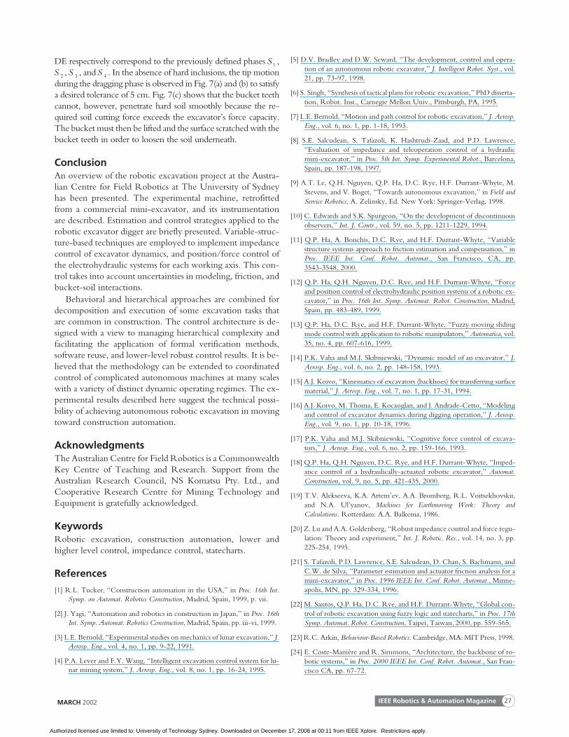
DE respectively correspond to the previously defined phases S 1 ,S 2 ,S 3 , andS 4 . In the absence of hard inclusions, the tip motionduring the dragging phase is observed in Fig. 7(a) and (b) to satisfya desired tolerance of 5 cm. Fig. 7(c) shows that the bucket teethcannot, however, penetrate hard soil smoothly because the re-quired soil cutting force exceeds the excavator’s force capacity.The bucket must then be lifted and the surface scratched with thebucket teeth in order to loosen the soil underneath.
ConclusionAn overview of the robotic excavation project at the Austra-lian Centre for Field Robotics at The University of Sydneyhas been presented. The experimental machine, retrofittedfrom a commercial mini-excavator, and its instrumentationare described. Estimation and control strategies applied to therobotic excavator digger are briefly presented. Variable-struc-ture-based techniques are employed to implement impedancecontrol of excavator dynamics, and position/force control ofthe electrohydraulic systems for each working axis. This con-trol takes into account uncertainties in modeling, friction, andbucket-soil interactions.
Behavioral and hierarchical approaches are combined fordecomposition and execution of some excavation tasks thatare common in construction. The control architecture is de-signed with a view to managing hierarchical complexity andfacilitating the application of formal verification methods,software reuse, and lower-level robust control results. It is be-lieved that the methodology can be extended to coordinatedcontrol of complicated autonomous machines at many scaleswith a variety of distinct dynamic operating regimes. The ex-perimental results described here suggest the technical possi-bility of achieving autonomous robotic excavation in movingtoward construction automation.
AcknowledgmentsThe Australian Centre for Field Robotics is a CommonwealthKey Centre of Teaching and Research. Support from theAustralian Research Council, NS Komatsu Pty. Ltd., andCooperative Research Centre for Mining Technology andEquipment is gratefully acknowledged.
KeywordsRobotic excavation, construction automation, lower andhigher level control, impedance control, statecharts.
References
[1] R.L. Tucker, “Construction automation in the USA,” in Proc. 16th Int.Symp. on Automat. Robotics Construction, Madrid, Spain, 1999, p. vii.
[2] J. Yagi, “Automation and robotics in construction in Japan,” in Proc. 16thInt. Symp. Automat. Robotics Construction, Madrid, Spain, pp. iii-vi, 1999.
[3] L.E. Bernold, “Experimental studies on mechanics of lunar excavation,” J.Aerosp. Eng., vol. 4, no. 1, pp. 9-22, 1991.
[4] P.A. Lever and F.Y. Wang, “Intelligent excavation control system for lu-nar mining system,” J. Aerosp. Eng., vol. 8, no. 1, pp. 16-24, 1995.
[5] D.V. Bradley and D.W. Seward, “The development, control and opera-tion of an autonomous robotic excavator,” J. Intelligent Robot. Syst., vol.21, pp. 73-97, 1998.
[6] S. Singh, “Synthesis of tactical plans for robotic excavation,” PhD disserta-tion, Robot. Inst., Carnegie Mellon Univ., Pittsburgh, PA, 1995.
[7] L.E. Bernold, “Motion and path control for robotic excavation,” J. Aerosp.Eng., vol. 6, no. 1, pp. 1-18, 1993.
[8] S.E. Salcudean, S. Tafazoli, K. Hashtrudi-Zaad, and P.D. Lawrence,“Evaluation of impedance and teleoperation control of a hydraulicmini-excavator,” in Proc. 5th Int. Symp. Experimental Robot., Barcelona,Spain, pp. 187-198, 1997.
[9] A.T. Le, Q.H. Nguyen, Q.P. Ha, D.C. Rye, H.F. Durrant-Whyte, M.Stevens, and V. Boget, “Towards autonomous excavation,” in Field andService Robotics, A. Zelinsky, Ed. New York: Springer-Verlag, 1998.
[10] C. Edwards and S.K. Spurgeon, “On the development of discontinuousobservers,” Int. J. Contr., vol. 59, no. 5, pp. 1211-1229, 1994.
[11] Q.P. Ha, A. Bonchis, D.C. Rye, and H.F. Durrant-Whyte, “Variablestructure systems approach to friction estimation and compensation,” inProc. IEEE Int. Conf. Robot. Automat., San Francisco, CA, pp.3543-3548, 2000.
[12] Q.P. Ha, Q.H. Nguyen, D.C. Rye, and H.F. Durrant-Whyte, “Forceand position control of electrohydraulic position systems of a robotic ex-cavator,” in Proc. 16th Int. Symp. Automat. Robot. Construction, Madrid,Spain, pp. 483-489, 1999.
[13] Q.P. Ha, D.C. Rye, and H.F. Durrant-Whyte, “Fuzzy moving slidingmode control with application to robotic manipulators,” Automatica, vol.35, no. 4, pp. 607-616, 1999.
[14] P.K. Vaha and M.J. Skibniewski, “Dynamic model of an excavator,” J.Aerosp. Eng., vol. 6, no. 2, pp. 148-158, 1993.
[15] A.J. Koivo, “Kinematics of excavators (backhoes) for transferring surfacematerial,” J. Aerosp. Eng., vol. 7, no. 1, pp. 17-31, 1994.
[16] A.J. Koivo, M. Thoma, E. Kocaoglan, and J. Andrade-Cetto, “Modelingand control of excavator dynamics during digging operation,” J. Aerosp.Eng., vol. 9, no. 1, pp. 10-18, 1996.
[17] P.K. Vaha and M.J. Skibniewski, “Cognitive force control of excava-tors,” J. Aerosp. Eng., vol. 6, no. 2, pp. 159-166, 1993.
[18] Q.P. Ha, Q.H. Nguyen, D.C. Rye, and H.F. Durrant-Whyte, “Imped-ance control of a hydraulically-actuated robotic excavator,” Automat.Construction, vol. 9, no. 5, pp. 421-435, 2000.
[19] T.V. Alekseeva, K.A. Artem’ev, A.A. Bromberg, R.L. Voitsekhovskii,and N.A. Ul’yanov, Machines for Earthmoving Work: Theory andCalculations. Rotterdam: A.A. Balkema, 1986.
[20] Z. Lu and A.A. Goldenberg, “Robust impedance control and force regu-lation: Theory and experiment,” Int. J. Robotic. Res., vol. 14, no. 3, pp.225-254, 1995.
[21] S. Tafazoli, P.D. Lawrence, S.E. Salcudean, D. Chan, S. Bachmann, andC.W. de Silva, “Parameter estimation and actuator friction analysis for amini-excavator,” in Proc. 1996 IEEE Int. Conf. Robot. Automat., Minne-apolis, MN, pp. 329-334, 1996.
[22] M. Santos, Q.P. Ha, D.C. Rye, and H.F. Durrant-Whyte, “Global con-trol of robotic excavation using fuzzy logic and statecharts,” in Proc. 17thSymp. Automat. Robot. Construction, Taipei, Taiwan, 2000, pp. 559-565.
[23] R.C. Arkin, Behaviour-Based Robotics. Cambridge, MA: MIT Press, 1998.
[24] E. Coste-Manière and R. Simmons, “Architecture, the backbone of ro-botic systems,” in Proc. 2000 IEEE Int. Conf. Robot. Automat., San Fran-cisco CA, pp. 67-72.
MARCH 2002 IEEE Robotics & Automation Magazine 27
Authorized licensed use limited to: University of Technology Sydney. Downloaded on December 17, 2008 at 00:11 from IEEE Xplore. Restrictions apply.
[25] B.P. Douglass, Real-Time UML: Developing Efficient Objects for EmbeddedSystems. Reading, MA: Addison-Wesley, 1999.
[26] K.Y. Fok and M.R. Fabuka, “A automatic navigation system for vi-sion-guided vehicles using a double heuristic and a finite state machine,”IEEE Trans. Robot. Automat., vol. 7, pp. 181-188, Feb. 1991.
Quang Ha received a B.E. in electrical engineering fromHo Chi Minh City University of Technology, Vietnam, in1983; a Ph.D. in engineering science from Moscow PowerInstitute, Russia, in 1992; and a Ph.D. in electrical engineer-ing from the University of Tasmania, Australia, in 1997.From 1997-2000, he was a senior research associate at theCentre for Field Robotics at The University of Sydney. He iscurrently a lecturer at the University of Technology, Syd-ney, Australia. His research interests include nonlinear con-trol, variable structure systems, robotics, and applications ofartificial intelligence in engineering.
Miguel Santos received a B.S. in electrical engineering fromthe Universidad Nacional de Ingenieria, Peru, in 1988 and aM.S. in engineering science from the University of NewSouth Wales, Australia, in 1995. His research interests includerobot architectures, fuzzy control, artificial intelligence, andits applications to construction and mining.
Quang Nguyen received a B.S. In electrical engineeringfrom Hanoi University of Technology, Vietnam, in 1993. Herecently graduated with a PH.D. from the Australian Centrefor Field Robotics, The University of Sydney, Australia. Hisresearch interests include nonlinear control, robotics and soft-ware engineering.
David Rye received a B.E. from Adelaide University, Aus-tralia, and a Ph.D. from The University of Sydney, Australia,
both in mechanical engineering, in 1980 and 1986, respec-tively. From 1986 to December 1987, he served as a lecturerin mechanical engineering at the Department of MechanicalEngineering at the University of Newcastle, Australia. Since1988, he has been with the Department of Mechanical andMechatronic Engineering, The University of Sydney, Aus-tralia, as a lecturer and then senior lecturer in mechanical en-gineering. Dr. Rye is a Deputy Director of the AustralianCentre for Field Robotics. His research interests include in-telligent and nonlinear control, autonomous excavation,crane dynamics and control, mechatronics and automation.
Hugh Durrant-Whyte received the B.S. in mechanical andnuclear engineering from the University of London, UK, in1983, and an M.S.E. and Ph.D. in systems engineering fromthe University of Pennsylvania, USA, in 1985 and 1986, re-spectively. From 1987-1995, he was a University Lecturer inEngineering Science, Oxford University, UK. Since July1995, he has been Professor of Mechatronic Engineering atthe Department of Mechanical and Mechatronic Engineering,The University of Sydney, Australia. Prof. Durrant-Whyte isthe Director of the Australian Centre for Field Robotics. Hisresearch interests include sensor data fusion, sensor systems,and mobile robotics.
Address for Correspondence: Dr. David Rye, Australian Cen-tre for Field Robotics, Rose Street Building J04, The Univer-sity of Sydney 2006, Australia. Phone: +61-2-9351-7126;Fax: +61-2-9351-7474; E-mail: [email protected]; Website: http://www.acfr.usyd.edu.au/.
MARCH 2002IEEE Robotics & Automation Magazine28
Authorized licensed use limited to: University of Technology Sydney. Downloaded on December 17, 2008 at 00:11 from IEEE Xplore. Restrictions apply.
Journal Results Page: lSI
SEARCH
WHArS NEW INRESEARCH
ISlJQurnal SelectionProcess Essay:lSI JoulJlal Selectionand EvaluationProcessISLLinksJournal CitationReports on the WeblSI Essential.ScienceIndicatorsISIWebofKnowledge
THOMSON
I S I
20f2
http://www.isinet.com/cgi-bin/jrnlst/jlresults.cgi?PC=MASTER&I...
lSI Master Journal ListSEARCH RESULTS
Search Terms: 1070-9932Total journals found: 1
The following title(s) matched your request:
Journals 1-1 (of 1) I FORMAT fOR PRINT
IEEE ROBOTICS & AUTOMATION MAGAZINE
QuarterlyISSN: 1070-9932IEEE-=INSTELECnUCAL_ELECIRONICSENGINEERSINC,345 E 47TH ST, NEW YORK, NY, 10017-2394
Journals 1-1 (of 1) I fORMAr fOR PRINT
6/05/2003 10:52 AM