A robotic hand rehabilitation system with interactive gaming using novel Electro-Rheological Fluid...
6
Abstract—A newly developed hand rehabilitation system is presented that combines robotics and interactive gaming to facilitate repetitive performance of task specific exercises for patients recovering from neurological motor deficits. A two degree of freedom robotic interface allows coordinated motions of the forearm and the hand (pronation/supination and grasp/release, respectively). It is driven by two novel Electro- Rheological Fluid based hydraulic actuators. Tests were conducted to characterize these actuators, and feed-forward controllers were developed for their force/torque control. A virtual reality environment (maze game) was developed in which the robot applies force fields to the user as the user navigates the environment, forming a haptic interface between the patient and the game. I. INTRODUCTION N the United States, stroke is a leading cause of long-term disability. According to statistics, about 780,000 Americans suffer a new or recurrent stroke each year. The direct and indirect cost of stroke for 2008 is estimated as $65.5 billion [1]. The physical effects of stroke are variable and may include impairment in motor and sensory systems, language, perception, emotional and cognitive function. One of the most disabling impairments resulting from stroke is the hemiparesis of the upper limb. This is because its impact on independence and quality of life is so marked. Stroke survivors typically receive intensive, hands-on physical and occupational therapy to encourage motor recovery. However, due to economic pressures on national care systems, patients are receiving less therapy and are discharged from rehabilitation hospitals sooner [2]. Robotic training is a considerably new technology that shows great potential for application in the field of neurorehabilitation as it has several advantages e.g., motivation, adaptability, data collection, and the ability to provide intensive individualized repetitive practice [3]. Studies on robotic devices for the upper extremity rehabilitation after stroke have shown This work was supported by WGI Inc., Southwick, MA, USA. O. Unluhisarcikli, B. Weinberg, M. Sivak, and C. Mavroidis are with the Department of Mechanical and Industrial Engineering, Northeastern University, Boston MA 02115 USA (phone: 617-373-4121; fax: 617-373- 2921; e-mail: [email protected] ). A. Mirelman is with Tel-Aviv Sourasky Medical Center (e-mail: [email protected]). P. Bonato is with the Harvard Medical School and Spaulding Rehabilitation Hospital (e-mail: [email protected] ). Corresponding author: C. Mavroidis * Both authors contributed equally. significant increases in upper limb function, dexterity and fine motor manipulations [4] as well as improved proximal motor control [5]. The potential benefits of robotic training have encouraged several research groups to develop robotic upper extremity rehabilitation systems [3, 6-8]. To the best of the authors’ knowledge, there is no existing robotic rehabilitator that facilitates and actuates grasp/release movements of the hand in conjunction with supination/pronation of the forearm. These movements are synergistic [9] and important to functional tasks such as eating, dressing and grooming. Therefore, regaining these core motor skills has high priority in the rehabilitation of individuals post stroke. A robotic retraining device focusing on these movements has the potential to help improve the quality of life of many patients. Our team at Northeastern University has developed various mechatronic devices in an effort to facilitate the rehabilitation of patients recovering from neurological ailments such as stroke. In our earlier work [10-12], we had developed a 1 degree of freedom (DoF) fMRI compatible Variable Resistance Hand Device (VRHD) to be used as an evaluation tool for development of innovative rehabilitation protocols. The fMRI compatibility was achieved through the use of an electro-rheological fluid (ERF) based damper that allowed tunable, computer controlled resistive force generation. Since the damper is a resistive element, its use was limited to higher level patients who could complete the entire exercise on their own. In this paper, a new 2-DoF hand rehabilitation system that can generate active forces as well as resistive forces is presented (Fig. 1). The two DoFs that allow the coordinated movements of the forearm and hand are actuated by two novel hydraulic actuators (one linear, and one rotary). The actuators are based on electro-rheological smart fluid technology under closed loop force/torque control. Active and assisted hand movements can be performed as well as movements against resistance to enhance muscle strengthening when appropriate. ERF-actuators were chosen over conventional actuators due to their potential to be made fMRI compatible. The hardware is connected to a computer that provides a virtual reality-like simulation in order to enhance motor learning by engaging patients in the therapeutic exercise via interactive gaming. The simulation presents visuo motor integration tasks to the patient as part of the games, and challenging the patients with cognitive and problem solving tasks embedded in the games. A Robotic Hand Rehabilitation System with Interactive Gaming Using Novel Electro-Rheological Fluid Based Actuators Ozer Unluhisarcikli*, Student Member, IEEE, Brian Weinberg*, Student Member, IEEE, Mark Sivak, Student Member, IEEE, Anat Mirelman, Paolo Bonato, Member, IEEE, and Constantinos Mavroidis, Member, IEEE I 2010 IEEE International Conference on Robotics and Automation Anchorage Convention District May 3-8, 2010, Anchorage, Alaska, USA 978-1-4244-5040-4/10/$26.00 ©2010 IEEE 1846
-
Upload
independent -
Category
Documents
-
view
2 -
download
0
Transcript of A robotic hand rehabilitation system with interactive gaming using novel Electro-Rheological Fluid...

Abstract—A newly developed hand rehabilitation system is presented that combines robotics and interactive gaming to facilitate repetitive performance of task specific exercises for patients recovering from neurological motor deficits. A two degree of freedom robotic interface allows coordinated motions of the forearm and the hand (pronation/supination and grasp/release, respectively). It is driven by two novel Electro-Rheological Fluid based hydraulic actuators. Tests were conducted to characterize these actuators, and feed-forward controllers were developed for their force/torque control. A virtual reality environment (maze game) was developed in which the robot applies force fields to the user as the user navigates the environment, forming a haptic interface between the patient and the game.
I. INTRODUCTION
N the United States, stroke is a leading cause of long-term disability. According to statistics, about 780,000
Americans suffer a new or recurrent stroke each year. The direct and indirect cost of stroke for 2008 is estimated as $65.5 billion [1]. The physical effects of stroke are variable and may include impairment in motor and sensory systems, language, perception, emotional and cognitive function. One of the most disabling impairments resulting from stroke is the hemiparesis of the upper limb. This is because its impact on independence and quality of life is so marked.
Stroke survivors typically receive intensive, hands-on physical and occupational therapy to encourage motor recovery. However, due to economic pressures on national care systems, patients are receiving less therapy and are discharged from rehabilitation hospitals sooner [2]. Robotic training is a considerably new technology that shows great potential for application in the field of neurorehabilitation as it has several advantages e.g., motivation, adaptability, data collection, and the ability to provide intensive individualized repetitive practice [3]. Studies on robotic devices for the upper extremity rehabilitation after stroke have shown
This work was supported by WGI Inc., Southwick, MA, USA. O. Unluhisarcikli, B. Weinberg, M. Sivak, and C. Mavroidis are with the
Department of Mechanical and Industrial Engineering, Northeastern University, Boston MA 02115 USA (phone: 617-373-4121; fax: 617-373-2921; e-mail: [email protected]).
A. Mirelman is with Tel-Aviv Sourasky Medical Center (e-mail: [email protected]).
P. Bonato is with the Harvard Medical School and Spaulding Rehabilitation Hospital (e-mail: [email protected]).
Corresponding author: C. Mavroidis * Both authors contributed equally.
significant increases in upper limb function, dexterity and fine motor manipulations [4] as well as improved proximal motor control [5].
The potential benefits of robotic training have encouraged several research groups to develop robotic upper extremity rehabilitation systems [3, 6-8]. To the best of the authors’ knowledge, there is no existing robotic rehabilitator that facilitates and actuates grasp/release movements of the hand in conjunction with supination/pronation of the forearm. These movements are synergistic [9] and important to functional tasks such as eating, dressing and grooming. Therefore, regaining these core motor skills has high priority in the rehabilitation of individuals post stroke. A robotic retraining device focusing on these movements has the potential to help improve the quality of life of many patients.
Our team at Northeastern University has developed various mechatronic devices in an effort to facilitate the rehabilitation of patients recovering from neurological ailments such as stroke. In our earlier work [10-12], we had developed a 1 degree of freedom (DoF) fMRI compatible Variable Resistance Hand Device (VRHD) to be used as an evaluation tool for development of innovative rehabilitation protocols. The fMRI compatibility was achieved through the use of an electro-rheological fluid (ERF) based damper that allowed tunable, computer controlled resistive force generation. Since the damper is a resistive element, its use was limited to higher level patients who could complete the entire exercise on their own.
In this paper, a new 2-DoF hand rehabilitation system that can generate active forces as well as resistive forces is presented (Fig. 1). The two DoFs that allow the coordinated movements of the forearm and hand are actuated by two novel hydraulic actuators (one linear, and one rotary). The actuators are based on electro-rheological smart fluid technology under closed loop force/torque control. Active and assisted hand movements can be performed as well as movements against resistance to enhance muscle strengthening when appropriate. ERF-actuators were chosen over conventional actuators due to their potential to be made fMRI compatible. The hardware is connected to a computer that provides a virtual reality-like simulation in order to enhance motor learning by engaging patients in the therapeutic exercise via interactive gaming. The simulation presents visuo motor integration tasks to the patient as part of the games, and challenging the patients with cognitive and problem solving tasks embedded in the games.
A Robotic Hand Rehabilitation System with Interactive Gaming Using Novel Electro-Rheological Fluid Based Actuators
Ozer Unluhisarcikli*, Student Member, IEEE, Brian Weinberg*, Student Member, IEEE, Mark Sivak, Student Member, IEEE, Anat Mirelman, Paolo Bonato, Member, IEEE,
and Constantinos Mavroidis, Member, IEEE
I
2010 IEEE International Conference on Robotics and AutomationAnchorage Convention DistrictMay 3-8, 2010, Anchorage, Alaska, USA
978-1-4244-5040-4/10/$26.00 ©2010 IEEE 1846
II. DESIGN AND DEVELOPMENT
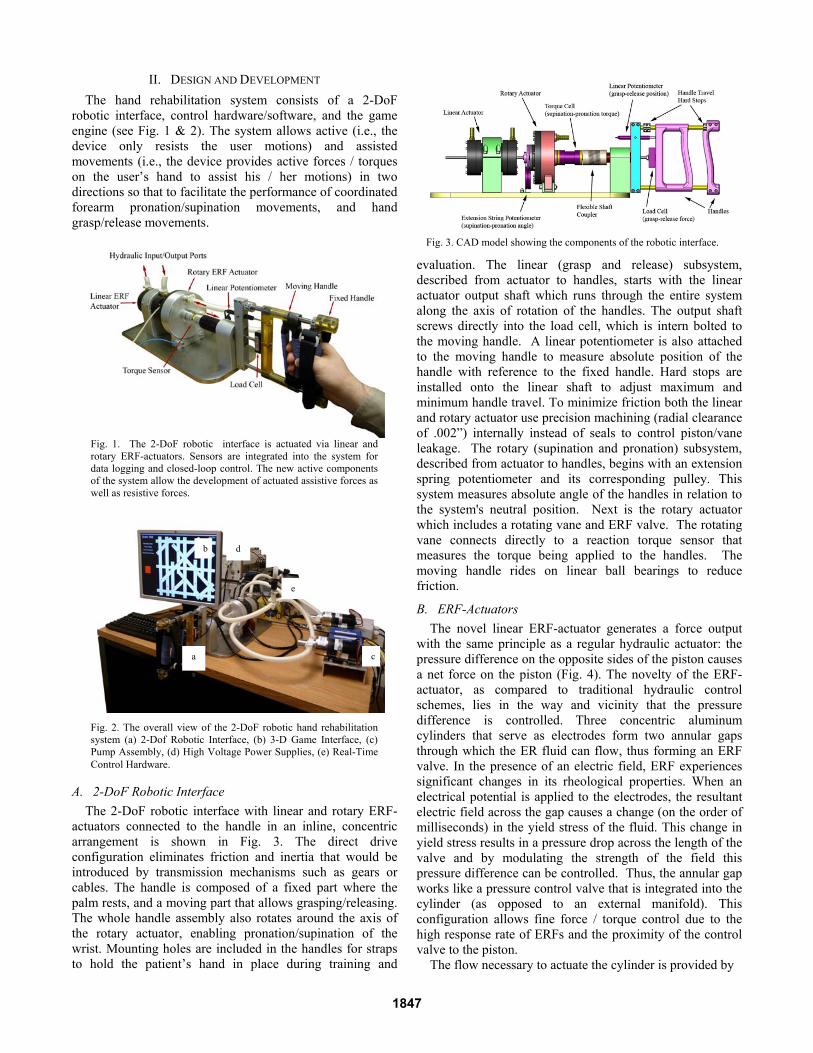
The hand rehabilitation system consists of a 2-DoF robotic interface, control hardware/software, and the game engine (see Fig. 1 & 2). The system allows active (i.e., the device only resists the user motions) and assisted movements (i.e., the device provides active forces / torques on the user’s hand to assist his / her motions) in two directions so that to facilitate the performance of coordinated forearm pronation/supination movements, and hand grasp/release movements.
A. 2-DoF Robotic Interface
The 2-DoF robotic interface with linear and rotary ERF-actuators connected to the handle in an inline, concentric arrangement is shown in Fig. 3. The direct drive configuration eliminates friction and inertia that would be introduced by transmission mechanisms such as gears or cables. The handle is composed of a fixed part where the palm rests, and a moving part that allows grasping/releasing. The whole handle assembly also rotates around the axis of the rotary actuator, enabling pronation/supination of the wrist. Mounting holes are included in the handles for straps to hold the patient’s hand in place during training and
evaluation. The linear (grasp and release) subsystem, described from actuator to handles, starts with the linear actuator output shaft which runs through the entire system along the axis of rotation of the handles. The output shaft screws directly into the load cell, which is intern bolted to the moving handle. A linear potentiometer is also attached to the moving handle to measure absolute position of the handle with reference to the fixed handle. Hard stops are installed onto the linear shaft to adjust maximum and minimum handle travel. To minimize friction both the linear and rotary actuator use precision machining (radial clearance of .002”) internally instead of seals to control piston/vane leakage. The rotary (supination and pronation) subsystem, described from actuator to handles, begins with an extension spring potentiometer and its corresponding pulley. This system measures absolute angle of the handles in relation to the system's neutral position. Next is the rotary actuator which includes a rotating vane and ERF valve. The rotating vane connects directly to a reaction torque sensor that measures the torque being applied to the handles. The moving handle rides on linear ball bearings to reduce friction.
B. ERF-Actuators
The novel linear ERF-actuator generates a force output with the same principle as a regular hydraulic actuator: the pressure difference on the opposite sides of the piston causes a net force on the piston (Fig. 4). The novelty of the ERF-actuator, as compared to traditional hydraulic control schemes, lies in the way and vicinity that the pressure difference is controlled. Three concentric aluminum cylinders that serve as electrodes form two annular gaps through which the ER fluid can flow, thus forming an ERF valve. In the presence of an electric field, ERF experiences significant changes in its rheological properties. When an electrical potential is applied to the electrodes, the resultant electric field across the gap causes a change (on the order of milliseconds) in the yield stress of the fluid. This change in yield stress results in a pressure drop across the length of the valve and by modulating the strength of the field this pressure difference can be controlled. Thus, the annular gap works like a pressure control valve that is integrated into the cylinder (as opposed to an external manifold). This configuration allows fine force / torque control due to the high response rate of ERFs and the proximity of the control valve to the piston.
The flow necessary to actuate the cylinder is provided by
Fig. 3. CAD model showing the components of the robotic interface.
Fig. 2. The overall view of the 2-DoF robotic hand rehabilitation system (a) 2-Dof Robotic Interface, (b) 3-D Game Interface, (c) Pump Assembly, (d) High Voltage Power Supplies, (e) Real-Time Control Hardware.
Fig. 1. The 2-DoF robotic interface is actuated via linear and rotary ERF-actuators. Sensors are integrated into the system for data logging and closed-loop control. The new active components of the system allow the development of actuated assistive forces as well as resistive forces.
b
a c
d
e
1847

a magnetic drive gear pump. The hydraulic pump is the key component of the ERF-actuator that distinguishes it from an ERF-damper. The resultant force and the velocity of the piston are dependent on the electrical field strength and the flow rate of the pump. The flow rate is regulated by a servo amplifier that controls the velocity of the pump.
The silicone oil/polyurethane particle based ERF, RheOil 1.1p3 from FUDICON GmbH, Darmstadt, was chosen because of its low dynamic viscosity (75 centipoises) and its non-abrasive nature. Dynamic force/torque requirements were obtained using spring based mock up devices and the system was dimensioned to accommodate the characteristics of the chosen ERF. The specifications are listed for a field strength of 3.25 kV/mm, which was chosen to reduce the probability of arcing due to electrical field breakdown (arcing). The maximum applicable field strength for the ERF actuators in this device is about 4.25 kV/mm. A controllable ratio of over 100 was obtained for both the linear and rotary actuator. Additional technical specifications of the actuators are summarized in Table 1.
C. Control Hardware & Software
The control hardware of the system consists of two PCs: a host computer, and a real-time target. The general framework representing the software running on each computer and their interaction is shown in Fig. 5. The host computer runs LabVIEW and the Panda3D game engine. The practitioner can modify the exercise parameters through their interface, and another monitor displays the virtual environment for the patient. Communication within the host computer between LabVIEW and Panda3D is done via User
Datagram Protocol (UDP), whereas communication between the host and the real-time target is carried out by the LabVIEW Shared Variable Engine. The real-time target is the dedicated controller of the system that runs all the time critical tasks such as data acquisition and controls. Regular DAQ hardware running on a general-purpose operating system such as Windows cannot guarantee real-time performance. In contrast, real-time hardware running on real-time operating systems allows the programmer to prioritize tasks so that the most critical task can always take control of the processor when needed. The real-time target is equipped with a National Instruments 6259 M-Series I/O card. The digital controller implemented on the real-time target operates at a frequency of 5 kHz.
III. SYSTEM CHARACTERIZATION
Tests were conducted to identify the response of the actuators to two control inputs: a) the electric field strength across the valve (kV/mm), and b) the flow rate of the pump (cc/sec). To eliminate the effect of fluid flow caused by the piston displacement, all tests were conducted whilst the actuator rod was fixed (static conditions). To isolate the effect of one control input from the other, one of the control inputs was fixed while the other one was varied. For clarity, only the most significant results for the linear ERF-Actuator are presented here. Similar tests were performed and similar results were obtained for the rotary ERF actuator.
A. Electric Field Step Input
A series of tests measured the actuator’s response to a step electric field input. The results show that the force profile over time has two distinct responses depending on the flow rate (Fig. 6). At low flow rates the force is saturated at some point, whereas at higher flow rates the force exhibits oscillations around almost the same level regardless of the flow rate. To explain this phenomenon, one needs to understand the mechanisms of the electro-rheological (ER) effect. At zero electric field these particles are randomly scattered. In the presence of an electric field, the particles in the suspension are polarized and aligned along the direction of the electric field due to the electric dipole moment and
Fig. 5. The framework displaying the interactions of the system within itself and with the users.
TABLE 1: TECHNICAL SPECIFICATION FOR ERF ACTUATORS
Property Linear
Actuator Rotary
Actuator
stroke length / rotation range 55 mm 216° maximum force / maximum torque 350 N 5.5 Nm maximum velocity 5.98 cm/s 30.3 RPM zero field resistive force / torque 3 N 0.05 Nm weight (actuator body only) 0.68 kg 1.77 kg length 127 mm 76.2 mm diameter 88.9 mm 140 mm
Fig. 4. The cross-section view of the ERF-actuators. The arrows show the direction of flow in the linear actuator (left). Dark arrows indicate higher pressure, and the light arrows indicate lower pressure. The pressure drop that is controlled by the electric field across the valve causes a net force on the piston. The rotary actuator (right) works with the same basic principle, except the piston is replaced by a rotary vane.
1848

form fibrillated structures. When the ER fluid flows through the valve, old chains are broken and new chains form continuously. However, when the flow rate is not high enough to break this structure the valve locks up and blocks any fluid flow. All of the fluid provided by the pump is forced through the piston sealing as leakage. The force reading is merely the result of the pressure drop caused by the leakage of the piston, which does not change over time. When the valve locks up, control over the force via electric field is lost. This situation is undesirable and should be avoided by keeping the flow rate above a critical limit. At flow rates above this limit, the responses become similar. It may be suggested that the force is independent of the flow rate after a critical limit, which is discussed further in the next section with an electric field ramp input test.
A close observation of the step response reveals that the force reaches a peak in the first 100 milliseconds, drops, and then starts increasing slowly with significant oscillations (Fig. 7). This test captures the time-dependent behavior of the system. The peak forces occurring in the initial response may represent the high frequency characteristics of the system.
It is possible to use these values to create a relationship
(called in this work as the inverse model) between electric field and force. Fig. 8 shows peak force measurements corresponding to several electric field inputs at 22.75 cc/sec flow rate. In contrast to the non-linear behavior of ERFs, the curve obtained from this extrapolation is linear.
B. Electric Field Ramp Input
The electric field ramp test gives a direct relationship between the applied electric field and the force. However the time-dependent characteristics cannot be observed from this test and the results will vary for different slopes of the voltage ramp. As discussed earlier, the output force saturates at some point depending on the flow rate. This phenomenon is even more evident in the voltage ramp test (Fig. 9). Before saturation, the curves show a similar trend regardless of the flow rate. However, at low flow rates the force becomes almost constant after a respective voltage. This is where the valve locks up and the force saturates. By making sure that the flow rate is above the minimum for the desired force this situation may be avoided (e.g. to achieve 150 N, the flow rate must be over 13.65 cc/sec).
IV. CLOSED-LOOP CONTROL
The time-variant and uncertain behavior of ERFs makes the use of a closed-loop controller necessary. To achieve accurate force/torque control, a feed-forward controller is developed based on the findings from the system characterization tests described in the previous section. The controller is implemented digitally on the real-time target via LabVIEW Real-Time, and runs at 5 kHz.
The block diagram of the controller for each actuator (linear or rotary) is shown in Fig. 10 and 11. Fig. 10 is the overall control block diagram while Fig. 11 is a close up to the force control algorithm. The inverse model obtained from the step response tests (Fig. 8) is used as the feed-forward term of the controller that converts the desired force/torque to control command. A Proportional-Integral (PI) controller corrects the error due to any model mismatch
Fig. 9. The electric field ramp input test shows how force changes with the field strength at different flow rates.
Fig. 8. The inverse model relating electric field to the peak values obtained from the step response tests.
Fig. 7. The close-up of the step response of the linear actuator to a 2 kV/mm electric field at 22.75 cc/sec flow rate. The response is time-variant and uncertain
Fig. 6. The step response of the linear actuator to a 2 kV/mm electric field at four different flow rates.
1849

Fig. 10. The generic control diagram of the system.
and uncertainty by acting upon the error between the desired and actual force/torque. The output is subject to saturation to avoid excessive control commands. The feed-forward term takes care of the non-linearity of the system, and makes it possible to use lower controller gains.
Representative step and sinusoidal response test results of
the closed-loop force controller for the linear actuator are shown in Fig. 12. Similar closed loop control results were obtained for the rotary actuator, as well.
V. VIRTUAL ENVIRONMENT
The benefits of using virtual environments in rehabilitation are becoming more evident as virtual reality rehabilitation systems are being developed and clinically tested [13]. Virtual Reality can provide the patient with motivation and enjoyment that can enhance their motor rehabilitation with robotic system. The virtual reality software designed for this system has two components: the game interface, and the practitioner’s graphical user interface (GUI).
A. Game Interface
The 2-DOF robotic interface provides feedback between the virtual environment and the user. Fig. 13 shows a screen capture from the game that has been developed using the Panda3D game engine. A game engine like Panda3D is preferred over using LabVIEW in order to have the flexibility to design more advanced games in the future. The patient travels in a two dimensional maze using the hand interface; where the grasp/release corresponds to a motion in the vertical direction (up/down), and pronation/supination corresponds to a motion in the horizontal direction (left/right). The position on the screen is controlled indirectly by velocity modulation, whereas, the position of the handle defines the velocity vector of the user position marker (e.g. the more they grasp the handle, the faster they move downwards). Both DoF of the hand device can be used simultaneously in coordinated movements by the patient to navigate maze pathways that are neither horizontal nor vertical.
Fig. 13. Screen capture of the maze created using the Panda3D game engine. The patient travels through the maze using the 2-DoF robotic hand interface. Their progress is displayed on the left.
Fig. 12. Step and sinusoidal response test results for the linear actuator closed-loop force controller. The dark colored line represents the desired force, and the light colored line represents the actual force measurement.
Fig. 11. The block diagram of the feed-forward controller of the actuators. The output is saturated to prevent excessive commands that might otherwise damage the system. The inverse model calculates the estimated voltage for the desired force/torque, which is used as a feedforward term.
1850
The purpose of the game is to collect the green objects in the maze while avoiding the red ones. This goal presents visual motor integration tasks to the patients, challenging them with cognitive and problem solving tasks. The difficulty of the mazes and the level of force interaction associated with movements through the maze can be fully adjusted to suit the needs of the user.
B. Practitioner’s GUI
The Practitioner's GUI (Fig. 14) provides the practitioner with the ability to change the values of many customizable performance parameters of the system (i.e. stiffness, sensitivity, assistive force/torque), as well as displays for monitoring of the sensor data. Since the device is under full computer control, the parameters can be adjusted through the computer interface in real-time, saved under the patient’s name, and loaded for future sessions.
VI. HAPTICS
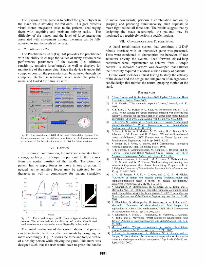
In its current configuration, the interface simulates linear springs, applying force/torque proportional to the distance from the neutral position of the handle. Therefore, the patient has to apply forces to move in one direction. If needed, active assistive forces may be activated by the therapist as well to compensate for patient spasticity.
The initial evaluation of the system shows that patients
can be motivated to do specific movements by designing the maze accordingly. Fig. 15 shows the force and torque profile of a healthy person while playing the game. This maze was designed such that the user would have to grasp the handle
to move downwards, perform a combination motion by grasping and pronating simultaneously, then supinate to move right collect all three dots. The results suggest that by designing the maze accordingly, the patients may be motivated to repetitively perform specific motions.
VII. CONCLUSIONS AND FUTURE WORK
A hand rehabilitation system that combines a 2-DoF robotic interface with an interactive game was presented. Tests were conducted to characterize the behavior of two actuators driving the system. Feed forward closed-loop controllers were implemented to achieve force / torque control. A software platform was developed that satisfies the flexibility required to address a wide variety of patients.
Future work includes clinical testing to study the efficacy of the device and the design and integration of an ergonomic handle design that mimics the natural grasping motion of the hand.
REFERENCES [1] "Heart Disease and Stroke Statistics—2008 Update," American Heart
Association, Dallas, Texas 2008. [2] B. H. Dobkin, "The economic impact of stroke," Neurol., vol. 45,
1995. [3] P. S. Lum, C. G. Burgar, P. C. Shor, M. Majmundar, and M. V. d.
Loos, "Robot-assisted movement training compared with conventional therapy techniques for the rehabilitation of upper-limb motor function after stroke," Arch Phys Med Rehabil, vol. 83, pp. 952-959, 2002.
[4] H. I. Krebs, N. Hogan, M. L. Aisen, and B. T. Volpe, "Robot-aided neurorehabilitation," IEEE Transactions on Rehabilitation Engineering, vol. 6, pp. 75-87, 1998.
[5] D. Jack, R. Boian, A. S. Merians, M. Tremaine, G. C. Burdea, S. V. Adamovich, M. Recce, and H. Poizner, "Virtual reality-enhanced stroke rehabilitation," IEEE Transactions on Neural Systems and Rehabilitation Engineering, vol. 9, pp. 308-318, 2001.
[6] N. Hogan, H. I. Krebs, A. Sharon, and J. Charnnarong, "Interactive Robotic Therapist," MIT, Ed. United States, 1995.
[7] R. L. Farshid, F. Amirabdollahian, M. Topping, B. Driessen, and W. Harwin, "Upper Limb Robot Mediated Stroke Therapy—GENTLE/s Approach," Autonomous Robots, vol. 15, pp. 35-51, 2003.
[8] D. J. Reinkensmeyer, K. Leonard E, M. Averbuch, A. McKenna-Cole, B. D. Schmit, and W. Z. Rymer, "Understending and treating arm movement impairment after chronic brain injury: Progress with the ARM guide," Journal of Rehabilitation Research & Development, vol. 37, pp. 653-662, 2000.
[9] H. A. H. Jongen, J. J. D. v. d. Gon, and C. C. A. M. Gielen, "Activation of human arm muscles during flexion/extension and supination/pronation tasks: a theory on muscle coordination," Biological Cybernetics, vol. 61, pp. 1-9, 1989.
[10] A. Khanicheh, D. Mintzopoulos, B. Weinberg, A. A. Tzika, and C. Mavroidis, "MR_CHIROD v.2: magnetic resonance compatible smart hand rehabilitation device for brain imaging," IEEE Transactions on Neural Systems and Rehabilitation Engineering, vol. 16, pp. 91-98, 2008.
[11] A. Khanicheh, D. Mintzopoulos, B. Weinberg, A. A. Tzika, and C. Mavroidis, "Evaluation of electrorheological fluid dampers for applications at 3-Tesla MRI environment," IEEE/ASME Transactions on Mechatronics, vol. 13, pp. 286-294, 2008.
[12] A. Khanicheh, A. Muto, C. Triantafyllou, B. Weinberg, L. Astrakas, A. Tzika, and C. Mavroidis, "fMRI-compatible rehabilitation hand device," Journal of Neuroengineering and Rehabilitation, vol. 3, p. 24, 2006.
[13] M. K. Holden, "Virtual environments for motor rehabilitation: review," Cyberpsychol Behav, vol. 8, pp. 187-211, 2005.
[14] P. Lum, D. Reinkensmeyer, R. Mahoney, W. Z. Rymer, and C. Burgar, "Robotic devices for movement therapy after stroke: current status and challenges to clinical acceptance," Top Stroke Rehabil, vol. 8, pp. 40-53, 2002.
Fig. 15. Force and torque profile from a typical rehabilitation exercise. The arrows indicate the direction of motion. Coordinated hand movements are required to move diagonally.in the caption.
Fig. 14: The practitioner’s GUI of the hand rehabilitation system. The device parameters such as stiffness, sensitivity, level of assistance can be customized for the patient and saved to disk for future sessions
1851