
mb_manual_z590-gaming-x-ax_e.pdf - Gigabyte
52
To reduce the impacts on global warming, the packaging materials of this product are recyclable and reusable. GIGABYTE works with you to protect the environment. For more product details, please visit GIGABYTE's website. Z590 GAMING X Z590 GAMING X AX Z590 GAMING X AX Z590 GAMING X User's Manual Rev. 1001 12ME-Z59GX-1001R
-
Upload
khangminh22 -
Category
Documents
-
view
4 -
download
0
Transcript of mb_manual_z590-gaming-x-ax_e.pdf - Gigabyte

To reduce the impacts on global warming, the packaging materials of this product are recyclable and reusable. GIGABYTE works with you to protect the environment.
For more product details, please visit GIGABYTE's website.
Z590 GAMING XZ590 GAMING X AX
Z590 GAMING X AXZ590 GAMING X
User's ManualRev. 100112ME-Z59GX-1001R

Copyright© 2021 GIGA-BYTE TECHNOLOGY CO., LTD. All rights reserved.The trademarks mentioned in this manual are legally registered to their respective owners.
DisclaimerInformation in this manual is protected by copyright laws and is the property of GIGABYTE.Changes to the specifications and features in this manual may be made by GIGABYTE without prior notice. No part of this manual may be reproduced, copied, translated, transmitted, or published in any form or by any means without GIGABYTE's prior written permission.
� In order to assist in the use of this product, carefully read the User's Manual. � For product-related information, check on our website at: https://www.gigabyte.com
Identifying Your Motherboard RevisionThe revision number on your motherboard looks like this: "REV: X.X." For example, "REV: 1.0" means the revision of the motherboard is 1.0. Check your motherboard revision before updating motherboard BIOS, drivers, or when looking for technical information.
Example:

- 3 -
Table of Contents
Z590 GAMING X AX/Z590 GAMING X Motherboard Layout ..........................................4
Chapter 1 Hardware Installation .....................................................................................51-1 Installation Precautions .................................................................................... 51-2 ProductSpecifications ...................................................................................... 61-3 Installing the CPU .......................................................................................... 101-4 Installing the Memory ..................................................................................... 101-5 Installing an Expansion Card ......................................................................... 111-6 Back Panel Connectors .................................................................................. 111-7 Internal Connectors ........................................................................................ 13
Chapter 2 BIOS Setup ..................................................................................................242-1 Startup Screen ............................................................................................... 242-2 The Main Menu .............................................................................................. 252-3 Smart Fan 6 .................................................................................................. 262-4 Favorites (F11) ............................................................................................... 272-5 Tweaker .......................................................................................................... 282-6 Settings .......................................................................................................... 342-7 System Info. ................................................................................................... 392-8 Boot ................................................................................................................ 402-9 Save & Exit ..................................................................................................... 43
Chapter 3 Appendix ......................................................................................................443-1 ConfiguringaRAIDSet .................................................................................. 443-2 Installing Intel® Optane™ Memory and Storage Management ........................ 453-3 DriversInstallation .......................................................................................... 47
RegulatoryNotices .................................................................................................... 48Contact Us ................................................................................................................ 52

j Only for the Z590 GAMING X AX.- 4 -
Z590 GAMING X AX/Z590 GAMING X Motherboard Layout
* The box contents above are for reference only and the actual items shall depend on the product package you obtain. The box contents are subject to change without notice.
Box Contents 5 Z590 GAMING X AX or Z590 GAMING X motherboard 5 Motherboard driver disc 5 One antennaj 5 User's Manual 5 M.2 screws 5 Two SATA cables
Temperature sensor
KB_MS_USB
M2_WIFIj
DP
U32G2C
U32_LAN
LGA1200ATX
AUDIO
ATX_12V_2X4
Intel® Z590
CLR_CMOSM_BIOS
PCIEX1_1
PCIEX4
PCIEX16
PCIEX1_2
F_U3
2
F_U3
2C
M2A_
SBM2
P_CP
U
CODEC
Z590 GAMING X (AX)
F_PANEL
F_USB1
F_USB2COM
LED_C2
LED_C1
D_LED2
F_AUDIO
D_LED1SPDIF_O
SYS_FAN3
SYS_
FAN4
QFLASH_PLUS
SPI_TPM
SYS_FAN1
USB 2.0 Hub
USB 2.0 Hub
SYS_FAN2
CPU_FAN
iTE® Super I/O
60
60
60
80
80
80
110
110
110
SATA
35
31
42
0
BAT
Realtek® 2.5GbE LAN
CPU DRAMVGA BOOT
U32_G2
THB_C1
THB_C2
M2M_
SB
ATX_12V_2X2
QFLED
DDR4
_A1
DDR4
_A2
DDR4
_B1
DDR4
_B2

Chapter 1 Hardware Installation1-1 Installation PrecautionsThe motherboard contains numerous delicate electronic circuits and components which can become damagedasaresultofelectrostaticdischarge(ESD).Priortoinstallation,carefullyreadtheuser'smanual and follow these procedures:
• Prior to installation, make sure the chassis is suitable for the motherboard. • Prior to installation, do not remove or break motherboard S/N (Serial Number) sticker or
warranty sticker provided by your dealer. These stickers are required for warranty validation. • Always remove the AC power by unplugging the power cord from the power outlet before
installing or removing the motherboard or other hardware components. • When connecting hardware components to the internal connectors on the motherboard, make
sure they are connected tightly and securely. • When handling the motherboard, avoid touching any metal leads or connectors. • It is best towear an electrostatic discharge (ESD)wrist strapwhen handling electroniccomponentssuchasamotherboard,CPUormemory.IfyoudonothaveanESDwriststrap,keepyourhandsdryandfirsttouchametalobjecttoeliminatestaticelectricity.
• Prior to installing the motherboard, please have it on top of an antistatic pad or within an electrostatic shielding container.
• Before connecting or unplugging the power supply cable from the motherboard, make sure the power supply has been turned off.
• Before turning on the power, make sure the power supply voltage has been set according to the local voltage standard.
• Before using the product, please verify that all cables and power connectors of your hardware components are connected.
• To prevent damage to the motherboard, do not allow screws to come in contact with the motherboard circuit or its components.
• Make sure there are no leftover screws or metal components placed on the motherboard or within the computer casing.
• Donotplacethecomputersystemonanunevensurface. • Donotplacethecomputersysteminahigh-temperatureorwetenvironment. • Turning on the computer power during the installation process can lead to damage to system
components as well as physical harm to the user. • If you are uncertain about any installation steps or have a problem related to the use of the product,pleaseconsultacertifiedcomputertechnician.
• If you use an adapter, extension power cable, or power strip, ensure to consult with its installation and/or grounding instructions.
- 5 -

1-2 ProductSpecificationsCPU � LGA1200 package:
- 11th Generation Intel® Core™ i9 processors/Intel® Core™ i7 processors/Intel® Core™ i5 processors
- 10th Generation Intel® Core™ i9 processors/Intel® Core™ i7 processors/Intel® Core™ i5 processors/Intel® Core™ i3 processors/Intel® Pentium® processors/Intel® Celeron® processors
(Go to GIGABYTE's website for the latest CPU support list.) � L3 cache varies with CPU
Chipset � Intel® Z590 Express Chipset
Memory � 11th Generation Intel® Core™ i9/i7/i5 processors:- SupportforDDR43200/3000/2933/2666/2400/2133MHzmemorymodules
� 10th Generation Intel® Core™ i9/i7 processors:- SupportforDDR42933/2666/2400/2133MHzmemorymodules
� 10th Generation Intel® Core™ i5/i3/Pentium®/Celeron® processors:- SupportforDDR42666/2400/2133MHzmemorymodules
� 4xDDR4DIMMsocketssupportingupto128GB(32GBsingleDIMMcapacity)of system memory
� Dualchannelmemoryarchitecture � Support forECCUn-bufferedDIMM1Rx8/2Rx8memorymodules (operate in
non-ECC mode) � Supportfornon-ECCUn-bufferedDIMM1Rx8/2Rx8/1Rx16memorymodules � SupportforExtremeMemoryProfile(XMP)memorymodules
(Go to GIGABYTE's website for the latest supported memory speeds and memory modules.)
Onboard Graphics
� Integrated Graphics Processor-Intel®HDGraphicssupport:- 1xDisplayPort,supportingamaximumresolutionof4096x2304@60Hz
* SupportforDisplayPort1.2versionandHDCP2.3(GraphicsspecificationsmayvarydependingonCPUsupport.)
Audio � Realtek® audio codec � HighDefinitionAudio � 2/4/5.1/7.1-channel � SupportforS/PDIFOut
LAN � Realtek® 2.5GbE LAN chip (2.5 Gbit/1 Gbit/100 Mbit)
Wireless Communication Modulej
� Intel® Wi-Fi 6 AX201- WIFIa,b,g,n,acwithwave2features,ax,supporting2.4/5GHzDual-Band- BLUETOOTH 5- Supportfor11ax160MHzwirelessstandardandupto2.4Gbpsdatarate
* Actual data rate may vary depending on environment and equipment.
j Only for the Z590 GAMING X AX.
- 6 -

Expansion Slots � 1 x PCI Express x16 slot, running at x16 (PCIEX16)* For optimum performance, if only one PCI Express graphics card is to be installed,
be sure to install it in the PCIEX16 slot.(The PCIEX16 slot conforms to PCI Express 4.0 standard.) (Note)
� 1 x PCI Express x16 slot, running at x4 (PCIEX4) � 2 x PCI Express x1 slots
(The PCIEX4 and PCI Express x1 slots conform to PCI Express 3.0 standard.)Multi-Graphics Technology � SupportforAMDQuad-GPUCrossFire™and2-WayAMDCrossFire™ technologies
Storage Interface � CPU:- 1 x M.2 connector (Socket 3, M key, type 2260/2280/22110 PCIe 4.0 x4/x2
SSDsupport)(M2P_CPU) (Note)
� Chipset:- 2 x M.2 connectors (Socket 3, M key, type 2260/2280/22110 SATA and PCIe
3.0x4/x2SSDsupport)(M2A_SB)(M2M_SB)- 6 x SATA 6Gb/s connectors
� SupportforRAID0,RAID1,RAID5,andRAID10* Referto"1-7InternalConnectors,"fortheinstallationnoticesfortheM.2andSATA
connectors. � Intel® Optane™MemoryReady
USB � Chipset:- 1 x USB Type-C® port on the back panel, with USB 3.2 Gen 2 support- 1 x USB Type-C® port with USB 3.2 Gen 1 support, available through the
internal USB header- 1 x USB 3.2 Gen 2 Type-A port (red) on the back panel- 7 x USB 3.2 Gen 1 ports (5 ports on the back panel, 2 ports available through
the internal USB header) � Chipset+2 USB 2.0 Hubs:
- 6 x USB 2.0/1.1 ports (2 ports on the back panel, 4 ports available through the internal USB headers)
Internal Connectors
� 1 x 24-pin ATX main power connector � 1 x 8-pin ATX 12V power connector � 1 x 4-pin ATX 12V power connector � 1 x CPU fan header � 4 x system fan headers � 2xaddressableLEDstripheaders � 2xRGBLEDstripheaders � 6 x SATA 6Gb/s connectors � 3 x M.2 Socket 3 connectors � 1 x front panel header � 1 x front panel audio header � 1xS/PDIFOutheader � 1 x USB Type-C® header, with USB 3.2 Gen 1 support � 1 x USB 3.2 Gen 1 header � 2 x USB 2.0/1.1 headers
(Note) Supported by 11th Generation processors only.
- 7 -

Internal Connectors
� 1 x Trusted Platform Module header (For the GC-TPM2.0 SPI/GC-TPM2.0 SPI 2.0 module only)
� 2 x Thunderbolt™ add-in card connectors � 1 x serial port header � 1 x Clear CMOS jumper � 1 x Q-Flash Plus button
Back Panel Connectors
� 1 x PS/2 keyboard/mouse port � 2xSMAantennaconnectors(2T2R)j � 1 x USB Type-C® port, with USB 3.2 Gen 2 support � 1xDisplayPort � 1 x USB 3.2 Gen 2 Type-A port (red) � 5 x USB 3.2 Gen 1 ports � 2 x USB 2.0/1.1 ports � 1xRJ-45port � 6 x audio jacks
I/O Controller � iTE® I/O Controller Chip
Hardware Monitor
� Voltage detection � Temperature detection � Fan speed detection � Fan fail warning � Fan speed control
* Whether the fan speed control function is supported will depend on the cooler you install.
BIOS � 1x256Mbitflash � Use of licensed AMI UEFI BIOS � PnP1.0a,DMI2.7,WfM2.0,SMBIOS2.7,ACPI5.0
Unique Features � Support for APP Center* Available applications in APP Center may vary by motherboard model. Supported functionsofeachapplicationmayalsovarydependingonmotherboardspecifications.
- @BIOS- EasyTune- Fast Boot- Game Boost- ON/OFF Charge- RGBFusion- Smart Backup- System Information Viewer
� Support for Q-Flash Plus � Support for Q-Flash � Support for Xpress Install
j Only for the Z590 GAMING X AX.
- 8 -

Bundled Software
� Norton® Internet Security (OEM version) � Realtek® 8125 Gaming LAN Bandwidth Control Utility
Operating System � Support for Windows 10 64-bit
Form Factor � ATX Form Factor; 30.5cm x 24.4cm
* GIGABYTEreservestherighttomakeanychangestotheproductspecificationsandproduct-relatedinformationwithoutprior notice.
Please visit the Support\Utility List page on GIGABYTE's website to download the latest version of apps.
Please visit GIGABYTE's website for support lists of CPU, memory modules,SSDs,andM.2devices.
Z590 GAMING XZ590 GAMING X AX
- 9 -

1-3 Installing the CPUReadthefollowingguidelinesbeforeyoubegintoinstalltheCPU: • Make sure that the motherboard supports the CPU.
(Go to GIGABYTE's website for the latest CPU support list.) • Always turn off the computer and unplug the power cord from the power outlet before installing the CPU
to prevent hardware damage. • Locate the pin one of the CPU. The CPU cannot be inserted if oriented incorrectly. (Or you may locate
the notches on both sides of the CPU and alignment keys on the CPU socket.) • Apply an even and thin layer of thermal grease on the surface of the CPU. • Donotturnonthecomputer if theCPUcooler isnot installed,otherwiseoverheatinganddamageof
the CPU may occur. • Set theCPUhost frequency inaccordancewith theCPUspecifications. It isnot recommended thatthesystembusfrequencybesetbeyondhardwarespecificationssinceitdoesnotmeetthestandardrequirementsfortheperipherals.Ifyouwishtosetthefrequencybeyondthestandardspecifications,pleasedosoaccordingtoyourhardwarespecificationsincludingtheCPU,graphicscard,memory,harddrive,etc.
Installing the CPULocate the alignment keys on the motherboard CPU socket and the notches on the CPU.
Do not remove the CPU socket cover before inserting the CPU. It may pop off from the load plate automatically during the process of re-engaging the lever after you insert the CPU.
1-4 Installing the MemoryReadthefollowingguidelinesbeforeyoubegintoinstallthememory: • Make sure that the motherboard supports the memory. It is recommended that memory of the same
capacity, brand, speed, and chips be used.(Go to GIGABYTE's website for the latest supported memory speeds and memory modules.)
• Always turn off the computer and unplug the power cord from the power outlet before installing the memory to prevent hardware damage.
• Memory modules have a foolproof design. A memory module can be installed in only one direction. If you are unable to insert the memory, switch the direction.
DualChannelMemoryConfigurationThismotherboardprovidesfourmemorysocketsandsupportsDualChannelTechnology.Afterthememoryisinstalled,theBIOSwillautomaticallydetectthespecificationsandcapacityofthememory.EnablingDualChannel memory mode will double the original memory bandwidth.
Please visit GIGABYTE's website for details on hardware installation.
Triangle Pin One Marking on the CPU
NotchNotch
LGA1200 CPU
Alignment Key
Alignment Key
LGA1200 CPU Socket
Pin One Corner of the CPU Socket
The four memory sockets are divided into two channels and each channel has two memory sockets as following: �ChannelA:DDR4_A1,DDR4_A2 �ChannelB:DDR4_B1,DDR4_B2
- 10 -

�RecommandedDualChannelMemoryConfiguration:DDR4_A1 DDR4_A2 DDR4_B1 DDR4_B2
2 Modules - - DS/SS - - DS/SS4 Modules DS/SS DS/SS DS/SS DS/SS(SS=Single-Sided,DS=Double-Sided,"--"=NoMemory)
DuetoCPUlimitations,readthefollowingguidelinesbeforeinstallingthememoryinDualChannelmode.1. DualChannelmodecannotbeenabledifonlyonememorymoduleisinstalled.2. WhenenablingDualChannelmodewithtwoorfourmemorymodules,itisrecommendedthatmemory
of the same capacity, brand, speed, and chips be used.
1-5 Installing an Expansion CardReadthefollowingguidelinesbeforeyoubegintoinstallanexpansioncard: • Make sure the motherboard supports the expansion card. Carefully read the manual that came
with your expansion card. • Always turn off the computer and unplug the power cord from the power outlet before installing an
expansion card to prevent hardware damage.
1-6 Back Panel Connectors
USB 2.0/1.1 PortTheUSBportsupportstheUSB2.0/1.1specification.UsethisportforUSBdevices.PS/2 Keyboard/Mouse PortUse this port to connect a PS/2 mouse or keyboard.SMA Antenna Connectors (2T2R)jUse this connector to connect an antenna.
After installing theDisplayPortdevice,makesure toset thedefaultsoundplaybackdevice toDisplayPort.(Theitemnamemaydifferdependingonyouroperatingsystem.)
• Whenremovingthecableconnectedtoabackpanelconnector,firstremovethecablefromyour device and then remove it from the motherboard.
• Whenremovingthecable,pullitstraightoutfromtheconnector.Donotrockitsidetosidetoprevent an electrical short inside the cable connector.
j Only for the Z590 GAMING X AX.
Tighten the antennas to the antenna connectors and then aim the antennas correctly for better signal reception.
USB Type-C® PortThereversibleUSBportsupportstheUSB3.2Gen2specificationandiscompatibletotheUSB3.2Gen1 andUSB2.0specification.UsethisportforUSBdevices.DisplayPortDisplayPortdelivershighqualitydigitalimagingandaudio,supportingbi-directionalaudiotransmission.DisplayPortcansupporttheHDCP2.3contentprotectionmechanism.YoucanusethisporttoconnectyourDisplayPort-supportedmonitor.Note:TheDisplayPortTechnologycansupportamaximumresolutionof4096x2304@60Hzbuttheactualresolutionssupporteddependonthemonitorbeingused.
j
- 11 -

USB 3.2 Gen 1 PortTheUSB3.2Gen1portsupports theUSB3.2Gen1specificationand iscompatible to theUSB2.0specification.UsethisportforUSBdevices.USB 3.2 Gen 2 Type-A Port (Red) (Q-Flash Plus Port)TheUSB3.2Gen2portsupportstheUSB3.2Gen2specificationandiscompatibletotheUSB3.2Gen1 andUSB2.0specification.UsethisportforUSBdevices.BeforeusingQ-FlashPlus(Note), make sure to inserttheUSBflashdriveintothisportfirst.RJ-45 LAN PortThe Gigabit Ethernet LAN port provides Internet connection at up to 2.5 Gbps data rate. The following describesthestatesoftheLANportLEDs.
ActivityLEDConnection/SpeedLED
LAN Port
Connection/SpeedLED:State DescriptionOrange 2.5 Gbps data rateGreen 1 Gbps data rateOff 100 Mbps data rate
ActivityLED:State DescriptionBlinking DatatransmissionorreceivingisoccurringOff No data transmission or receiving is occurring
Center/Subwoofer Speaker Out (Orange)Use this audio jack to connect center/subwoofer speakers.Rear Speaker Out (Black)Use this audio jack to connect rear speakers.Side Speaker Out (Gray)Use this audio jack to connect side speakers.Line In (Blue)The line in jack. Use this audio jack for line in devices such as an optical drive, walkman, etc.Line Out/Front Speaker Out (Green)The line out jack.Mic In (Pink)The Mic in jack.AudioJackConfigurations:
Jack Headphone/ 2-channel 4-channel 5.1-channel 7.1-channel
Center/Subwoofer Speaker Out a a
RearSpeakerOut a a a
Side Speaker Out a
Line InLine Out/Front Speaker Out a a a a
Mic In
PleasevisitGIGABYTE'swebsitefordetailsonconfiguringtheaudiosoftware.
(Note) ToenabletheQ-FlashPlusfunctionpleasevisitthe"UniqueFeatures"webpageofGIGABYTE'swebsite.
- 12 -
You can change the functionality of an audio jack using the audio software.

1-7 Internal Connectors
Readthefollowingguidelinesbeforeconnectingexternaldevices: • First make sure your devices are compliant with the connectors you wish to connect. • Before installing the devices, be sure to turn off the devices and your computer. Unplug the power
cord from the power outlet to prevent damage to the devices. • After installing the device and before turning on the computer, make sure the device cable has
been securely attached to the connector on the motherboard.
1) ATX_12V_2X2/ATX_12V_2X42) ATX3) CPU_FAN4) SYS_FAN1/2/3/45) LED_C1/LED_C26) D_LED1/D_LED27) SATA3 0/1/2/3/4/58) M2P_CPU/M2A_SB/M2M_SB9) F_PANEL
10) F_AUDIO11) SPDIF_O
12) F_U3213) F_U32C14) F_USB1/F_USB215) THB_C1/THB_C216) COM17) SPI_TPM18) CLR_CMOS19) BAT20) CPU/DRAM/VGA/BOOT21) QFLASH_PLUS
9 20
4
13
2
6
7
12
175 1610 11
14
6
18
19
14 415 21
3 5
8
8
8
4
- 13 -

DEBUG PORT
131
2412
ATX
1/2) ATX_12V_2X2/ATX_12V_2X4/ATX (2x2, 2x4, 12V Power Connectors and 2x12 Main Power Connector)
With the use of the power connector, the power supply can supply enough stable power to all the components onthemotherboard.Beforeconnectingthepowerconnector,firstmakesurethepowersupplyisturnedoff and all devices are properly installed. The power connector possesses a foolproof design. Connect the power supply cable to the power connector in the correct orientation.
The 12V power connector mainly supplies power to the CPU. If the 12V power connector is not connected, the computer will not start.
To meet expansion requirements, it is recommended that a power supply that can withstand high power consumption be used (500W or greater). If a power supply is used that does not provide the required power, the result can lead to an unstable or unbootable system.
ATX:
Pin No. Definition Pin No. Definition1 3.3V 13 3.3V2 3.3V 14 -12V3 GND 15 GND4 +5V 16 PS_ON (soft On/Off)5 GND 17 GND6 +5V 18 GND7 GND 19 GND8 Power Good 20 NC9 5VSB (stand by +5V) 21 +5V
10 +12V 22 +5V11 +12V (Only for 2x12-pin
ATX)23 +5V (Only for 2x12-pin
ATX)12 3.3V (Only for 2x12-pin
ATX)24 GND(Onlyfor2x12-pin
ATX)
ATX_12V_2X4:
Pin No. Definition Pin No. Definition1 GND(Onlyfor2x4-pin12V) 5 +12V (Only for 2x4-pin
12V)2 GND(Onlyfor2x4-pin12V) 6 +12V (Only for 2x4-pin
12V)3 GND 7 +12V4 GND 8 +12V
DEBUG PORT
ATX_12V_2X4
41
85
ATX_12V_2X2:
Pin No. Definition1 GND2 GND3 +12V4 +12V
ATX_12V_2X2
3 4
21
- 14 -

5) LED_C1/LED_C2 (RGB LED Strip Headers) Theheaderscanbeusedtoconnectastandard5050RGBLEDstrip(12V/G/R/B),withmaximumpower
rating of 2A (12V) and maximum length of 2m.
Pin No. Definition1 12V2 G3 R4 B
Before installing the devices, be sure to turn off the devices and your computer. Unplug the power cord from the power outlet to prevent damage to the devices.
Forhowtoturnon/offthelightsoftheLEDstrippleasevisitthe"UniqueFeatures"webpageofGIGABYTE's website.
1
DEBUG PORT
3/4) CPU_FAN/SYS_FAN1/2/3/4 (Fan Headers) All fan headers on this motherboard are 4-pin. Most fan headers possess a foolproof insertion design.
When connecting a fan cable, be sure to connect it in the correct orientation (the black connector wire is the ground wire). The speed control function requires the use of a fan with fan speed control design. For optimum heat dissipation, it is recommended that a system fan be installed inside the chassis.
• Be sure to connect fan cables to the fan headers to prevent your CPU and system from overheating. Overheating may result in damage to the CPU or the system may hang.
• Thesefanheadersarenotconfigurationjumperblocks.Donotplaceajumpercapontheheaders.
CPU_FAN
DEBUG PORT
DEBUG PORT
1
1
SYS_FAN1/SYS_FAN4
SYS_FAN3SYS_FAN2
DEBUG PORT
DEBUG PORT
1
1
Pin No. Definition1 GND2 Voltage Speed Control3 Sense4 PWM Speed Control
Connector CPU_FAN SYS_FAN1~4
Maximum Current 2A 2A
Maximum Power 24W 24W
- 15 -
ConnectyourRGBLEDstriptotheheader.Thepowerpin(markedwithatriangleontheplug)oftheLEDstripmustbeconnectedtoPin1 (12V) of this header. Incorrect connection may lead to the damage oftheLEDstrip.
RGBLEDStrip
112V

7) SATA3 0/1/2/3/4/5 (SATA 6Gb/s Connectors) The SATA connectors conform to SATA 6Gb/s standard and are compatible with SATA 3Gb/s and SATA
1.5Gb/s standard. Each SATA connector supports a single SATA device. The Intel®ChipsetsupportsRAID0,RAID1,RAID5,andRAID10.RefertoChapter3,"ConfiguringaRAIDSet,"forinstructionsonconfiguringaRAIDarray.
Pin No. Definition1 GND2 TXP3 TXN4 GND5 RXN6 RXP7 GND
Toenablehot-pluggingfortheSATAports,refertoChapter2,"BIOSSetup,""Settings\IOPorts\SATAAndRSTConfiguration,"formoreinformation.
1
1
SATA3 5 3 14 2 0
7
7
DEBUG PORT
DEBUG PORT
DEBUG PORT
6) D_LED1/D_LED2 (Addressable LED Strip Headers) Theheaderscanbeusedtoconnectastandard5050addressableLEDstrip,withmaximumpowerrating
of5A(5V)andmaximumnumberof1000LEDs.
Pin No. Definition1 V (5V)2 Data3 No Pin4 GND
1
Connect your addressable LEDstrip to the header.Thepower pin(markedwithatriangleontheplug)oftheLEDstripmustbeconnectedtoPin1oftheaddressableLEDstripheader.IncorrectconnectionmayleadtothedamageoftheLEDstrip.
F_US
B30
F_�U
������
�B_��
��
F_��
�������
F_��
�������
�����
����_��
�����
��B�
B��S
_������
��B�
S�B_
�������
��B�
���_���S
�� ��S_��
����_��
�����
��B�
���_��U
���_���
������B
�
��� ��������
�
������
��������
��������
��������
�����
��������
��������
������S
���
��������
��
���
123
���
123
�� �
1 2 3
���
123
1 1
1
1
B��S
�S����
��������
�����
����S�
��������
������
�_S�
��
����S�
������S
��������
U���
���
12
3�
�
������
��������
��������
��������
S�����
�3�B�
�S�S
��������
�S���
����
��������
��������
���U���
���_�
��_��
3
F_US
B3��F
��������
���
S���
_������
�
S���
_������
�
S���
_������
�
��������
��������
��������
S���F
�����
��� ��������
�
��B_�
��B_�
�������F
�
��_�0�
S�����
��S�
���
��_�0�
��������
F�����
���
��_��F
�
���_����
������
�_�����
���
��_����
��_B�
��� ��������
�
U��
S���
_S��
���_����
����S�
��F_��
�������
B��
USB�
0_�B
��B_�
��B_��
F_US
B3��
���F_
USB3
0�3��
����
���_���
������
��_3��
��������
����U�
S��_�
��
AddressableLEDStrip
1
Before installing the devices, be sure to turn off the devices and your computer. Unplug the power cord from the power outlet to prevent damage to the devices.
Forhowtoturnon/offthelightsoftheLEDstrippleasevisitthe"UniqueFeatures"webpageofGIGABYTE's website.
- 16 -

8) M2P_CPU (Note)/M2A_SB/M2M_SB (M.2 Socket 3 Connectors) TheM.2connectorssupportM.2SATASSDsorM.2PCIeSSDsandsupportRAIDconfiguration.Please
notethatanM.2PCIeSSDcannotbeusedtocreateaRAIDseteitherwithanM.2SATASSDoraSATAharddrive.RefertoChapter3,"ConfiguringaRAIDSet,"forinstructionsonconfiguringaRAIDarray.
FollowthestepsbelowtocorrectlyinstallanM.2SSDintheM.2connector.Step 1:LocatetheM.2connectorwhereyouwillinstalltheM.2SSD,useascrewdrivertounfastenthescrewonthe heatsink and then remove the heatsink. (Only the M2P_CPU and M2A_SB connectors has the heatsink)Step 2:LocatethepropermountingholebasedonthelengthofyourM.2SSDdrive.Ifneeded,movethestandofftothedesiredmountinghole.InserttheM.2SSDintotheM.2connectoratanangle.Step 3:Press theM.2SSDdownand thenuse the includedscrewtosecure it in theconnector.Replace theheatsinkandsecureit totheoriginalhole.Removetheprotectivefilmfromthebottomoftheheatsinkbefore replacing the heatsink.
M2P_CPU (Note)
F_USB30 F_�U������
�B_��� �
F_� �������� F_� �������������
����_���������B�
B��S_��������B�
S�B_���������B�
���_���S����S_������_���������B�
���_��U���_���������B�
������������
� ����������������������������������
����������������������S� �� ����������
���
123
���
123
���
123
�� �
1 2 3
1
1
1
1
B��S�S�����������������
����S���������������
�_S� ��
����S�������S��������U���
���
123��
� �����������������������������S������3� B��S�S���������S���
����
�������������������U����� �_���_�� 3
F_USB3��F�����������
S� �� _�������
S� �� _�������
S� �� _�������
������������������������S���F�����
������������
��B_�
��B_�
�������F�
��_�0�
S�������S����
��_�0���������F��������
��_��F�
���_����������
�_��������
��_������_B�
������������
U��
S� �� _S��
���_�������� S���F_���������
B� �
USB�0_�B
��B_�
��B_��
F_USB3����� F_USB30�3��
����
���_���
������
��_3��������������U�
S��_���
80110 60
M2A_SB
F_USB30 F_�U������
�B_��� �
F_� �������� F_� �������������
����_���������B�
B��S_��������B�
S�B_���������B�
���_���S����S_������_���������B�
���_��U���_���������B�
������������
� ����������������������������������
����������������������S� �� ����������
���
123
���
123
���
123
�� �
1 2 3
1
1
1
1
B��S�S�����������������
����S���������������
�_S� ��
����S�������S��������U���
���
123��
� �����������������������������S������3� B��S�S���������S���
����
�������������������U����� �_���_�� 3
F_USB3��F�����������
S� �� _�������
S� �� _�������
S� �� _�������
������������������������S���F�����
������������
��B_�
��B_�
�������F�
��_�0�
S�������S����
��_�0���������F��������
��_��F�
���_����������
�_��������
��_������_B�
������������
U��
S� �� _S��
���_�������� S���F_���������
B� �
USB�0_�B
��B_�
��B_��
F_USB3����� F_USB30�3��
����
���_���
������
��_3��������������U�
S��_���
80110 60
M2M_SB
F_USB30 F_�U������
�B_��� �
F_� �������� F_� �������������
����_���������B�
B��S_��������B�
S�B_���������B�
���_���S����S_������_���������B�
���_��U���_���������B�
������������
� ����������������������������������
����������������������S� �� ������������
�
123
���
123
���
123
�� �
1 2 3
1
1
1
1
B��S�S�����������������
����S���������������
�_S� ��
����S�������S��������U���
���
123��
� �����������������������������S������3� B��S�S���������S���
����
�������������������U����� �_���_�� 3
F_USB3��F�����������
S� �� _�������
S� �� _�������
S� �� _�������
������������������������S���F�����
������������
��B_�
��B_�
�������F�
��_�0�
S�������S����
��_�0���������F��������
��_��F�
���_����������
�_��������
��_������_B�
������������
U��
S� �� _S��
���_�������� S���F_���������
B� �
USB�0_�B
��B_�
��B_��
F_USB3����� F_USB30�3��
����
���_���
������
��_3��������������U�
S��_���
80110 60
(Note) Supported by 11th Generation processors only. Be sure to use Intel®SSDsifyouwanttosetupaRAIDconfigurationontheM2A_CPUconnector.
- 17 -

Installation Notices for the M.2 and SATA Connectors:The availability of the SATA connectors may be affected by the type of device installed in the M.2 sockets. The M2A_SB connector shares bandwidth with the SATA3 1 connector. The M2M_SB connector shares bandwidth withtheSATA34,5connectors.Refertothefollowingtablesfordetails.
• M2M_SB:
SATA3 0 SATA3 1 SATA3 2 SATA3 3 SATA3 4 SATA3 5
M.2SATASSD a a a a r r
M.2PCIeSSD a a a a r r
NoM.2SSDInstalled a a a a a a
a: Available, r: Not available
ConnectorType of M.2SSD
• M2A_SB:
SATA3 0 SATA3 1 SATA3 2 SATA3 3 SATA3 4 SATA3 5
M.2SATASSD a r a a a a
M.2PCIeSSD a a a a a a
NoM.2SSDInstalled a a a a a a
a: Available, r: Not available
ConnectorType of M.2SSD
• M2P_CPU (Note):
SATA3 0 SATA3 1 SATA3 2 SATA3 3 SATA3 4 SATA3 5
M.2PCIeSSD a a a a a a
NoM.2SSDInstalled a a a a a a
a: Available, r: Not available* TheconnectorsupportsonlyPCIeSSDs.
ConnectorType of M.2SSD
(Note) Supported by 11th Generation processors only. Be sure to use Intel®SSDsifyouwanttosetupaRAIDconfigurationontheM2A_CPUconnector.
- 18 -

The front panel design may differ by chassis. A front panel module mainly consists of power switch, resetswitch,powerLED,harddriveactivityLED,speakerandetc.Whenconnectingyourchassisfront panel module to this header, make sure the wire assignments and the pin assignments are matched correctly.
9) F_PANEL (Front Panel Header) Connect the power switch, reset switch, speaker, chassis intrusion switch/sensor and system status indicator
on the chassis to this header according to the pin assignments below. Note the positive and negative pins before connecting the cables.
System Status LEDS0 OnS3/S4/S5 Off
• PW(PowerSwitch,Red): Connects to the power switch on the chassis front panel. You may
configure theway to turn off your systemusing the power switch(refertoChapter2,"BIOSSetup,""Settings\PlatformPower,"formoreinformation).
• PLED/PWR_LED (PowerLED,Yellow/Purple):Connects to the power status indicator onthechassisfrontpanel.TheLEDisonwhenthesystemisoperating.TheLEDisoff when the system is in S3/S4 sleep state or powered off (S5).
• SPEAK (Speaker, Orange): Connects to the speaker on the chassis front panel. The system reports system startup status by issuing
a beep code. One single short beep will be heard if no problem is detected at system startup. • HD (HardDriveActivityLED,Blue): ConnectstotheharddriveactivityLEDonthechassisfrontpanel.TheLEDisonwhentheharddrive
is reading or writing data. • RES (ResetSwitch,Green):
Connects to the reset switch on the chassis front panel. Press the reset switch to restart the computer ifthecomputerfreezesandfailstoperformanormalrestart.
• CI (Chassis Intrusion Header, Gray): Connects to the chassis intrusion switch/sensor on the chassis that can detect if the chassis cover has
been removed. This function requires a chassis with a chassis intrusion switch/sensor. • NC (Orange): No Connection.
PowerLED
DEBUG PORT
12
1920
CI- CI
+
PWR_
LED-
PWR_
LED+
PLED
-
PW-
SPEA
K+
SPEA
K-PLED
+
PW+
PowerLED
HD-
RES+
HD+
RES-
HardDriveActivityLED
ResetSwitch Chassis Intrusion
Header
Power Switch Speaker
PWR_
LED-
NC NC
10) F_AUDIO (Front Panel Audio Header) ThefrontpanelaudioheadersupportsHighDefinitionaudio(HD).Youmayconnectyourchassisfront
panel audio module to this header. Make sure the wire assignments of the module connector match the pin assignments of the motherboard header. Incorrect connection between the module connector and the motherboard header will make the device unable to work or even damage it.
Some chassis provide a front panel audio module that has separated connectors on each wire instead of a single plug. For information about connecting the front panel audio module that has different wire assignments, please contact the chassis manufacturer.
F_USB30 F_�U������
�B_��� �
F_� �������� F_� �������������
����_���������B�
B��S_��������B�
S�B_���������B�
���_���S����S_������_���������B�
���_��U���_���������B�
������������
� ����������������������������������
����������������������S� �� ����������
���
123
���
123
���
123
�� �
1 2 3
1
1
1
1
B��S�S�����������������
����S���������������
�_S� ��
����S�������S��������U���
���
123��
� �����������������������������S������3� B��S�S���������S���
����
�������������������U����� �_���_�� 3
F_USB3��F�����������
S� �� _�������
S� �� _�������
S� �� _�������
������������������������S���F�����
������������
��B_�
��B_�
�������F�
��_�0�
S�������S����
��_�0���������F��������
��_��F�
���_����������
�_��������
��_������_B�
������������
U��
S� �� _S��
���_�������� S���F_���������
B� �
USB�0_�B
��B_�
��B_��
F_USB3����� F_USB30�3��
����
���_���
������
��_3��������������U�
S��_���
9 1
10 2
Pin No. Definition Pin No. Definition1 MIC2_L 6 Sense2 GND 7 FAUDIO_JD3 MIC2_R 8 No Pin4 NC 9 LINE2_L5 LINE2_R 10 Sense
- 19 -

11) SPDIF_O (S/PDIF Out Header) ThisheadersupportsS/PDIFdigitaloutput,whichallowsyoutoconnectaS/PDIFdigitalaudiocableto
output digital audio from your motherboard to the supported audio devices. For information about connecting the digital audio cable, carefully read the manual for your audio devices.
Pin No. Definition1 5VDUAL2 No Pin3 SPDIFO4 GND
1
F_USB30 F_�U������
�B_��� �
F_� �������� F_� �������������
����_���������B�
B��S_��������B�
S�B_���������B�
���_���S����S_������_���������B�
���_��U���_���������B�
������������
� ����������������������������������
����������������������S� �� ����������
���
123
���
123
���
123
�� �
1 2 3
1
1
1
1
B��S�S�����������������
����S���������������
�_S� ��
����S�������S��������U���
���
123��
� �����������������������������S������3� B��S�S���������S���
����
�������������������U����� �_���_�� 3
F_USB3��F�����������
S� �� _�������
S� �� _�������
S� �� _�������
������������������������S���F�����
������������
��B_�
��B_�
�������F�
��_�0�
S�������S����
��_�0���������F��������
��_��F�
���_����������
�_��������
��_������_B�
������������
U��
S� �� _S��
���_�������� S���F_���������
B� �
USB�0_�B
��B_�
��B_��
F_USB3����� F_USB30�3��
����
���_���
������
��_3��������������U�
S��_���
Pin No. Definition Pin No. Definition Pin No. Definition1 VBUS 8 D1- 15 SSTX2-2 SSRX1- 9 D1+ 16 GND3 SSRX1+ 10 NC 17 SSRX2+4 GND 11 D2+ 18 SSRX2-5 SSTX1- 12 D2- 19 VBUS6 SSTX1+ 13 GND 20 No Pin7 GND 14 SSTX2+
12) F_U32 (USB 3.2 Gen 1 Header) TheheaderconformstoUSB3.2Gen1andUSB2.0specificationandcanprovidetwoUSBports.For
purchasingtheoptional3.5"frontpanelthatprovidestwoUSB3.2Gen1ports,pleasecontactthelocaldealer.
F_USB30 F_�U������
�B_��� �
F_� �������� F_� �������������
����_���������B�
B��S_��������B�
S�B_���������B�
���_���S����S_������_���������B�
���_��U���_���������B�
������������
� ����������������������������������
����������������������S� �� ����������
���
123
���
123
���
123
�� �
1 2 3
1
1
1
1
B��S�S�����������������
����S���������������
�_S� ��
����S�������S��������U���
���
123��
� �����������������������������S������3� B��S�S���������S���
����
�������������������U����� �_���_�� 3
F_USB3��F�����������
S� �� _�������
S� �� _�������
S� �� _�������
������������������������S���F�����
������������
��B_�
��B_�
�������F�
��_�0�
S�������S����
��_�0���������F��������
��_��F�
���_����������
�_��������
��_������_B�
������������
U��
S� �� _S��
���_�������� S���F_���������
B� �
USB�0_�B
��B_�
��B_��
F_USB3����� F_USB30�3��
����
���_���
������
��_3��������������U�
S��_���
10
20 1
11
Pin No. Definition Pin No. Definition Pin No. Definition1 VBUS 8 CC1 15 RX2+2 TX1+ 9 SBU1 16 RX2-3 TX1- 10 SBU2 17 GND4 GND 11 VBUS 18 D-5 RX1+ 12 TX2+ 19 D+6 RX1- 13 TX2- 20 CC27 VBUS 14 GND
13) F_U32C (USB Type-C® Header with USB 3.2 Gen 1 Support) TheheaderconformstoUSB3.2Gen1specificationandcanprovideoneUSBport.
F_USB30 F_�U������
�B_��� �
F_� �������� F_� �������������
����_���������B�
B��S_��������B�
S�B_���������B�
���_���S����S_������_���������B�
���_��U���_���������B�
������������
� ����������������������������������
����������������������S� �� ������������
�
123
���
123
���
123
�� �
1 2 3
1
1
1
1
B��S�S�����������������
����S���������������
�_S� ��
����S�������S��������U���
���
123��
� �����������������������������S������3� B��S�S���������S���
����
�������������������U����� �_���_�� 3
F_USB3��F�����������
S� �� _�������
S� �� _�������
S� �� _�������
������������������������S���F�����
������������
��B_�
��B_�
�������F�
��_�0�
S�������S����
��_�0���������F��������
��_��F�
���_����������
�_��������
��_������_B�
������������
U��
S� �� _S��
���_�������� S���F_���������
B� �
USB�0_�B
��B_�
��B_��
F_USB3����� F_USB30�3��
����
���_���
������
��_3��������������U�
S��_���
20
10 11
1
- 20 -

15) THB_C1/THB_C2 (Thunderbolt™ Add-in Card Connectors) The connectors are used to connect to a GIGABYTE Thunderbolt™ add-in card.
Supports a Thunderbolt™ add-in card.
F_US
B30
F_�U
������
�B_��
��
F_��
�������
F_��
�������
�����
����_��
�����
��B�
B��S
_������
��B�
S�B_
�������
��B�
���_���S
�� ��S_��
����_��
�����
��B�
���_��U
���_���
������B
�
��� ��������
�
������
��������
��������
��������
�����
��������
��������
������S
���
��������
��
���
123
���
123
�� �
1 2 3
���
123
1 1
1
1
B��S
�S����
��������
�����
����S�
��������
������
�_S�
��
����S�
������S
��������
U���
���
12
3�
�
������
��������
��������
��������
S�����
�3�B�
�S�S
��������
�S���
����
��������
��������
���U���
���_�
��_��
3
F_US
B3��F
��������
���
S���
_������
�
S���
_������
�
S���
_������
�
��������
��������
��������
S���F
�����
��� ��������
�
��B_�
��B_�
�������F
�
��_�0�
S�����
��S�
���
��_�0�
��������
F�����
���
��_��F
�
���_����
������
�_�����
���
��_����
��_B�
��� ��������
�
U��
S���
_S��
���_����
����S�
��F_��
�������
B��
USB�
0_�B
��B_�
��B_��
F_US
B3��
���F_
USB3
0�3��
����
���_���
������
��_3��
��������
����U�
S��_�
��
F_USB30F_�U������
�B_����
F_���������F_��������������
����_���������B�
B��S_��������B�
S�B_���������B�
���_���S����S_������_���������B�
���_��U���_���������B�
������������
�����������������������������������
����������������������S���
����������
�� �
1 2 3
���
123
���
123
���
123
11
1
1
B��S�S�����������������
����S���������������
�_S���
����S�������S��������U���
���
12
3�
�
������������������������������S������3�B��S�S���������S���
����
�������������������U�����
�_���_��3
F_USB3��F�����������
S���_�������
S���_�������
S���_�������
������������������������S���F�����
������������
��B_�
��B_�
�������F�
��_�0�
S�������S����
��_�0���������F��������
��_��F�
���_����������
�_��������
��_������_B�
������������
U��
S���_S��
���_��������S���F_���������
B��
USB�0_�B
��B_�
��B_��
F_USB3�����
F_USB30�3��
����
���_���
������
��_3��������������U�
S��_���
1
THB_C1 THB_C2
1
10
9
2
1
16) COM (Serial Port Header) The COM header can provide one serial port via an optional COM port cable. For purchasing the optional
COM port cable, please contact the local dealer.
Pin No. Definition Pin No. Definition1 NDCD- 6 NDSR-2 NSIN 7 NRTS-3 NSOUT 8 NCTS-4 NDTR- 9 NRI-5 GND 10 No Pin
14) F_USB1/F_USB2 (USB 2.0/1.1 Headers) TheheadersconformtoUSB2.0/1.1specification.EachUSBheadercanprovidetwoUSBportsviaan
optional USB bracket. For purchasing the optional USB bracket, please contact the local dealer.
Pin No. Definition Pin No. Definition1 Power (5V) 6 USBDY+2 Power (5V) 7 GND3 USBDX- 8 GND4 USBDY- 9 No Pin5 USBDX+ 10 NC
• DonotplugtheIEEE1394bracket(2x5-pin)cableintotheUSB2.0/1.1header. • Prior to installing the USB bracket, be sure to turn off your computer and unplug the power cord
from the power outlet to prevent damage to the USB bracket.
DEBUG PORT
10
9
2
1
- 21 -

18) CLR_CMOS (Clear CMOS Jumper) UsethisjumpertocleartheBIOSconfigurationandresettheCMOSvaluestofactorydefaults.Toclear
the CMOS values, use a metal object like a screwdriver to touch the two pins for a few seconds.
• Always turn off your computer and unplug the power cord from the power outlet before clearing the CMOS values.
• Aftersystemrestart,gotoBIOSSetuptoloadfactorydefaults(selectLoadOptimizedDefaults)ormanuallyconfiguretheBIOSsettings(refertoChapter2,"BIOSSetup,"forBIOSconfigurations).
Open: Normal
Short: Clear CMOS Values
19) BAT (Battery) Thebatteryprovidespowertokeepthevalues(suchasBIOSconfigurations,date,andtimeinformation)
intheCMOSwhenthecomputeristurnedoff.Replacethebatterywhenthebatteryvoltagedropstoalowlevel, or the CMOS values may not be accurate or may be lost.
You may clear the CMOS values by removing the battery:1. Turn off your computer and unplug the power cord.2. Gently remove the battery from the battery holder and wait for one minute. (Or use a metal
object like a screwdriver to touch the positive and negative terminals of the battery holder, making them short for 5 seconds.)
3. Replacethebattery.4. Plug in the power cord and restart your computer.
• Always turn off your computer and unplug the power cord before replacing the battery. • Replacethebatterywithanequivalentone.Damagetoyourdevicesmayoccurifthebatteryis
replaced with an incorrect model. • Contact the place of purchase or local dealer if you are not able to replace the battery by yourself
or uncertain about the battery model. • When installing the battery, note the orientation of the positive side (+) and the negative side (-)
of the battery (the positive side should face up). • Used batteries must be handled in accordance with local environmental regulations.
12
11
2
1
17) SPI_TPM (Trusted Platform Module Header) You may connect an SPI TPM (Trusted Platform Module) to this header.
Pin No. Definition Pin No. Definition1 DataOutput 7 Chip Select2 Power (3.3V) 8 GND3 No Pin 9 IRQ4 NC 10 NC5 DataInput 11 NC6 CLK 12 RST
F_USB30 F_�U������
�B_��� �
F_� �������� F_� �������������
����_���������B�
B��S_��������B�
S�B_���������B�
���_���S����S_������_���������B�
���_��U���_���������B�
������������
� ����������������������������������
����������������������S� �� ����������
���
123
���
123
���
123
�� �
1 2 3
1
1
1
1
B��S�S�����������������
����S���������������
�_S� ��
����S�������S��������U���
���
123��
� �����������������������������S������3� B��S�S���������S���
����
�������������������U����� �_���_�� 3
F_USB3��F�����������
S� �� _�������
S� �� _�������
S� �� _�������
������������������������S���F�����
������������
��B_�
��B_�
�������F�
��_�0�
S�������S����
��_�0���������F��������
��_��F�
���_����������
�_��������
��_������_B�
������������
U��
S� �� _S��
���_�������� S���F_���������
B� �
USB�0_�B
��B_�
��B_��
F_USB3����� F_USB30�3��
����
���_���
������
��_3��������������U�
S��_���
- 22 -

21) QFLASH_PLUS (Q-Flash Plus Button) Q-Flash Plus allows you to update the BIOS when your system is off (S5 shutdown state). Save the latest
BIOSonaUSBthumbdriveandplugitintotheQ-FlashPlusport,andthenyoucannowflashtheBIOSautomaticallybysimplypressingtheQ-FlashPlusbutton.TheQFLEDwillflashwhentheBIOSmatchingandflashingactivitiesstartandwillstopflashingwhenthemainBIOSflashingiscomplete.
ForhowtouseQ-FlashPluspleasevisitthe"UniqueFeatures"webpageofGIGABYTE'swebsite.
QFLASH_PLUS
QFLED
20) CPU/DRAM/VGA/BOOT (Status LEDs) The statusLEDs showwhether theCPU,memory, graphics card, andoperating systemareworking
properlyaftersystempower-on.IftheCPU/DRAM/VGALEDison,thatmeansthecorrespondingdeviceisnotworkingnormally;iftheBOOTLEDison,thatmeansyouhaven'tenteredtheoperatingsystemyet.
CPU: CPUstatusLEDDRAM: MemorystatusLEDVGA: GraphicscardstatusLEDBOOT: OperatingsystemstatusLED
F_USB30 F_�U������
�B_��� �
F_� �������� F_� �������������
����_���������B�
B��S_��������B�
S�B_���������B�
���_���S����S_������_���������B�
���_��U���_���������B�
������������
� ����������������������������������
����������������������S� �� ����������
���
123
���
123
���
123
�� �
1 2 3
1
1
1
1
B��S�S�����������������
����S���������������
�_S� ��
����S�������S��������U���
���
123��
� �����������������������������S������3� B��S�S���������S���
����
�������������������U����� �_���_�� 3
F_USB3��F�����������
S� �� _�������
S� �� _�������
S� �� _�������
������������������������S���F�����
������������
��B_�
��B_�
�������F�
��_�0�
S�������S����
��_�0���������F��������
��_��F�
���_����������
�_��������
��_������_B�
������������
U��
S� �� _S��
���_�������� S���F_���������
B� �
USB�0_�B
��B_�
��B_��
F_USB3����� F_USB30�3��
����
���_���
������
��_3��������������U�
S��_���
- 23 -
CPU DRAMVGA BOOT

BIOS (Basic Input and Output System) records hardware parameters of the system in the CMOS on the motherboard. Its major functions include conducting the Power-On Self-Test (POST) during system startup, saving system parameters and loading operating system, etc. BIOS includes a BIOS Setup program that allows theusertomodifybasicsystemconfigurationsettingsortoactivatecertainsystemfeatures.When the power is turned off, the battery on the motherboard supplies the necessary power to the CMOS to keeptheconfigurationvaluesintheCMOS.ToaccesstheBIOSSetupprogram,pressthe<Delete>keyduringthePOSTwhenthepoweristurnedon.ToupgradetheBIOS,useeithertheGIGABYTEQ-Flashor@BIOSutility. • Q-Flash allows the user to quickly and easily upgrade or back up BIOS without entering the operating system. • @BIOSisaWindows-basedutilitythatsearchesanddownloadsthelatestversionofBIOSfromtheInternet
and updates the BIOS.
Chapter 2 BIOS Setup
• BecauseBIOSflashingispotentiallyrisky,ifyoudonotencounterproblemsusingthecurrentversionofBIOS,itisrecommendedthatyounotflashtheBIOS.ToflashtheBIOS,doitwithcaution.InadequateBIOSflashingmay result in system malfunction.
• It is recommended that you not alter the default settings (unless you need to) to prevent system instability or other unexpected results. Inadequately altering the settings may result in system's failure to boot. If this occurs, try to cleartheCMOSvaluesandresettheboardtodefaultvalues.(Refertothe"LoadOptimizedDefaults"sectioninthis chapter or introductions of the battery/clear CMOS jumper in Chapter 1 for how to clear the CMOS values.)
2-1 Startup ScreenThe following startup Logo screen will appear when the computer boots.
• When the system is not stable as usual, select the Load Optimized Defaults item to set your system to its defaults. • The BIOS Setup menus described in this chapter are for reference only and may differ by BIOS version.
TherearetwodifferentBIOSmodesasfollowsandyoucanusethe<F2>keytoswitchbetweenthetwomodes.Easy Mode allows users to quickly view their current system information or to make adjustments for optimum performance.InEasyMode,youcanuseyourmousetomovethroughconfigurationitems.TheAdvancedModeprovides detailed BIOS settings. You can press the arrow keys on your keyboard to move among the items andpress<Enter>toacceptorenterasub-menu.Oryoucanuseyourmousetoselecttheitemyouwant.
Function Keys
- 24 -

2-2 The Main Menu
Advanced Mode Function Keys<f><g> Move the selection bar to select a setup menu<h><i> Movetheselectionbartoselectanconfigurationitemonamenu<Enter>/DoubleClick Execute command or enter a menu<+>/<PageUp> Increase the numeric value or make changes<->/<PageDown> Decreasethenumericvalueormakechanges<F1> Show descriptions of the function keys<F2> Switch to Easy Mode<F3> SavethecurrentBIOSsettingstoaprofile<F4> LoadtheBIOSsettingsfromaprofilecreatedbefore<F5> RestorethepreviousBIOSsettingsforthecurrentsubmenus<F6> DisplaytheSmartFan6screen<F7> LoadtheOptimizedBIOSdefaultsettingsforthecurrentsubmenus<F8> Access the Q-Flash utility<F10> Save all the changes and exit the BIOS Setup program<F11> Switch to the Favorites submenu<F12> Capture the current screen as an image and save it to your USB drive<Insert> Add or remove a favorite option<Ctrl>+<S> Displayinformationontheinstalledmemory<Esc> Main Menu: Exit the BIOS Setup program
Submenus: Exit current submenu
Hardware Information
ConfigurationItems Current Settings
Setup Menus
ConfigurationItems
System Time
Quick Access Bar allows you to quickly move to the General Help, Easy Mode, Smart Fan 6, or Q-Flash screen.
- 25 -

Usethe<F6>functionkeytoquicklyswitchtothisscreen.Thisscreenallowsyoutoconfigurefanspeedrelatedsettings for each fan header or monitor your system/CPU temperature.
& TUNE ALL Allows you to apply the current settings to all fan headers.
& Temperature Displaysthecurrenttemperatureoftheselectedtargetarea.
& Fan Speed Displayscurrentfanspeeds.
& Fan Speed Control Allows you to determine whether to enable the fan speed control function and adjust the fan speed.
�Normal Allows the fan to run at different speeds according to the temperature. You can adjust the fan speed with System Information Viewer based on your system requirements. (Default)
�Silent Allows the fan to run at slow speeds. �Manual Allows you to drag the curve nodes to adjust fan speed. Or you can use the EZ Tuning
feature. After adjusting the node position, press Apply to automatically calculate the slope of the curve.
�Full Speed Allows the fan to run at full speeds. & Fan Control Use Temperature Input
Allows you to select the reference temperature for fan speed control. & Temperature Interval
Allows you to select the temperature interval for fan speed change. & FAN Control Mode
�Auto Lets the BIOS automatically detect the type of fan installed and sets the optimal control mode.(Default)
�Voltage Voltage mode is recommended for a 3-pin fan. �PWM PWM mode is recommended for a 4-pin fan.
2-3 Smart Fan 6
- 26 -

& FAN Stop Enables or disables the fan stop function. You can set the temperature limit using the temperature curve.
Thefanstopsoperationwhenthetemperatureislowerthanthelimit.(Default:Disabled) & FAN Mode
Allows you to set the operating mode for the fan. �Slope Adjuststhefanspeedlinearlybasedonthetemperature.(Default) �Stair Adjusts the fan speed stepwise based on the temperature.
& FAN Fail Warning Allows the system to emit warning sound if the fan is not connected or fails. Check the fan condition or fan
connectionwhenthisoccurs.(Default:Disabled) & SaveFanProfile
Thisfunctionallowsyoutosavethecurrentsettingstoaprofile.YoucansavetheprofileintheBIOSorselect Select File in HDD/FDD/USBtosavetheprofiletoyourstoragedevice.
& LoadFanProfile ThisfunctionallowsyoutoloadapreviouslysavedBIOSprofilewithoutthehasslesofreconfiguringthe
BIOS settings. Or you can select Select File in HDD/FDD/USBtoloadaprofilefromyourstoragedevice.
2-4 Favorites (F11)
Setyourfrequentlyusedoptionsasyourfavoritesandusethe<F11>keytoquicklyswitchtothepagewhereall of your favorite options are located. To add or remove a favorite option, go to its original page and press <Insert>ontheoption.Theoptionismarkedwithastarsignifsetasa"favorite."
- 27 -

Whether the system will work stably with the overclock/overvoltage settings you made is dependent on your overall systemconfigurations.Incorrectlydoingoverclock/overvoltagemayresultindamagetoCPU,chipset,ormemoryand reduce the useful life of these components. This page is for advanced users only and we recommend you not to alter the default settings to prevent system instability or other unexpected results. (Inadequately altering the settings may result in system's failure to boot. If this occurs, clear the CMOS values and reset the board to default values.)
& CPU Upgrade AllowsyoutosettheCPUfrequency.ThefinalresultmayvarydependingontheCPUused.Optionsare:
Default,GamingProfile,AdvancedProfile.(Default:Default) & CPU Base Clock
AllowsyoutomanuallysettheCPUbaseclockin0.01MHzincrements.(Default:Auto) Important: It is highly recommended that the CPU frequency be set in accordance with the CPU
specifications. & PVD Ratio Threshold Override (Note)
AllowsyoutodeterminewhethertoimproveperformanceunderextremeBCLKOCbyreducinga"PLLBanding"conditioncausedinpartbyaveryhighDCOfrequency.(Default:Auto)
& Enhanced Multi-Core Performance DetermineswhethertoallowtheCPUtorunatTurbo1Cspeed.(Default:Auto)
& CPU Clock Ratio Allows you to alter the clock ratio for the installed CPU. The adjustable range is dependent on the CPU
being installed. & Ring Ratio
AllowsyoutosettheCPUUncoreratio.TheadjustablerangeisdependentontheCPUbeingused.(Default:Auto)
& IGP Ratio (Note)
AllowsyoutosettheGraphicsRatio.(Default:Auto) & AVX Disable (Note)
AllowsyoutodisabletheAVXinstructionsetsonaCPUthatsupportsAVX.(Default:Auto) & AVX512 Disable (Note)
AllowsyoutodisabletheAVX-512instructionsetsonaCPUthatsupportsAVX-512.(Default:Auto)
(Note) This item is present only when you install a CPU that supports this feature. For more information about Intel® CPUs' unique features, please visit Intel's website.
2-5 Tweaker
- 28 -

& AVX Offset (Note)
AVXoffsetisthenegativeoffsetofAVXratio.(Default:Auto) & AVX512 Offset (Note)
AVXoffsetisthenegativeoffsetofAVX512ratio.(Default:Auto) & AVX Voltage Guardband Scale Factor (Note)
AllowsyoutolowerthestandardAVXvoltage.(Default:Auto) & AVX512 Voltage Guardband Scale Factor (Note)
AllowsyoutolowerthestandardAVX-512voltage.(Default:Auto)
� Advanced CPU Settings & Core Fused Max Core Ratio (Note)
Displaysthehighestfrequencyofeachcore. & CPU Over Temperature Protection (Note)
Allowsyoutofine-tunetheTJMaxoffsetvalue.(Default:Auto) & FCLK Frequency for Early Power On (Note)
AllowsyoutosettheFCLKfrequency.Optionsare:Normal(800Mhz),1GHz,400MHz.(Default:1GHz) & Hyper-Threading Technology
Allows you to determine whether to enable multi-threading technology when using an Intel® CPU that supports this function. This feature only works for operating systems that support multi-processor mode. AutoletstheBIOSautomaticallyconfigurethissetting.(Default:Auto)
& No. of CPU Cores Enabled Allows you to select the number of CPU cores to enable in an Intel® multi-core CPU (the number of CPU
cores may vary by CPU). AutoletstheBIOSautomaticallyconfigurethissetting.(Default:Auto) & Intel(R) Speed Shift Technology (Intel® Speed Shift Technology) (Note)
Enables or disables Intel® Speed Shift Technology. Enabling this feature allows the processor to ramp up itsoperatingfrequencymorequicklyandthenimprovesthesystemresponsiveness.(Default:Enabled)
& CPU Thermal Monitor (Note)
Enables or disables Intel® Thermal Monitor function, a CPU overheating protection function. When enabled, the CPU core frequency and voltage will be reduced when the CPU is overheated. Auto lets the BIOS automaticallyconfigurethissetting.(Default:Auto)
& Ring to Core offset (Down Bin) AllowsyoutodeterminewhethertodisabletheCPURingratioauto-downfunction.Auto lets the BIOS
automaticallyconfigurethissetting.(Default:Auto) & CPU EIST Function (Note)
Enables or disables Enhanced Intel®SpeedStepTechnology(EIST).DependingonCPUloading,Intel® EIST technology can dynamically and effectively lower the CPU voltage and core frequency to decrease average power consumption and heat production. AutoletstheBIOSautomaticallyconfigurethissetting.(Default:Auto)
& Race To Halt (RTH) (Note)/EnergyEfficientTurbo (Note)
EnablesordisablestheCPUpowersavingrelatedsettings.(Default:Auto) & Intel(R) Turbo Boost Technology (Note)
Allows you to determine whether to enable the Intel® CPU Turbo Boost technology. Auto lets the BIOS automaticallyconfigurethissetting.(Default:Auto)
(Note) This item is present only when you install a CPU that supports this feature. For more information about Intel® CPUs' unique features, please visit Intel's website.
- 29 -

& Intel(R) Turbo Boost Max Technology 3.0 (Note)
Enables or disables Intel® Turbo Boost Max Technology 3.0. Intel® Turbo Boost Max Technology 3.0 allows the system to identify the processor's best performance core and lets you manually direct the most critical workloadstoit.Youcanevenadjustthefrequencyofeachcoreindividuallyforperformanceoptimization.(Default:Enabled)
& CPU Flex Ratio Override EnablesordisablestheCPUFlexRatio.ThemaximumCPUclockratiowillbebasedontheCPU Flex
Ratio Settings value if CPU Clock Ratio is set to Auto.(Default:Disabled) & CPU Flex Ratio Settings
AllowsyoutosettheCPUFlexRatio.TheadjustablerangemayvarybyCPU. & Frequency Clipping TVB (Note)
Allows you to enable or disable automatic CPU frequency reduction initiated by Thermal Velocity Boost. AutoletstheBIOSautomaticallyconfigurethissetting.(Default:Auto)
& Voltage reduction initiated TVB (Note)
Allows you to enable or disable automatic CPU voltage reduction initiated by Thermal Velocity Boost. Auto letstheBIOSautomaticallyconfigurethissetting.(Default:Auto)
d Active Turbo Ratios & Turbo Ratio (Core Active)
Allows you to set the CPU Turbo ratios for different number of active cores. Auto sets the CPU Turbo ratios accordingtotheCPUspecifications.ThisitemisconfigurableonlywhenActive Turbo Ratios is set to Manual.(Default:Auto)
d Per Core HT Disable Setting & HT Disable (Note)
AllowsyoutodeterminewhethertodisabletheHTfeatureforeachCPUcore.Thisitemisconfigurableonly when Per Core HT Disable Setting is set to Manual.(Default:Disabled)
d C-States Control & CPU Enhanced Halt (C1E)
Enables or disables Intel® CPU Enhanced Halt (C1E) function, a CPU power-saving function in system halt state. When enabled, the CPU core frequency and voltage will be reduced during system halt state to decrease power consumption. AutoletstheBIOSautomaticallyconfigurethissetting.Thisitemisconfigurableonlywhen C-States Control is set to Enabled.(Default:Auto)
& C3 State Support (Note)
Allows you to determine whether to let the CPU enter C3 mode in system halt state. When enabled, the CPU core frequency and voltage will be reduced during system halt state to decrease power consumption. The C3 state is a more enhanced power-saving state than C1. AutoletstheBIOSautomaticallyconfigurethissetting.ThisitemisconfigurableonlywhenC-States Control is set to Enabled.(Default:Auto)
& C6/C7 State Support Allows you to determine whether to let the CPU enter C6/C7 mode in system halt state. When enabled, the
CPU core frequency and voltage will be reduced during system halt state to decrease power consumption. The C6/C7 state is a more enhanced power-saving state than C3. AutoletstheBIOSautomaticallyconfigurethissetting.ThisitemisconfigurableonlywhenC-States Control is set to Enabled.(Default:Auto)
(Note) This item is present only when you install a CPU that supports this feature. For more information about Intel® CPUs' unique features, please visit Intel's website.
- 30 -

& C8 State Support (Note 1)
Allows you to determine whether to let the CPU enter C8 mode in system halt state. When enabled, the CPU core frequency and voltage will be reduced during system halt state to decrease power consumption. The C8 state is a more enhanced power-saving state than C6/C7. AutoletstheBIOSautomaticallyconfigurethissetting.ThisitemisconfigurableonlywhenC-States Control is set to Enabled.(Default:Auto)
& C10 State Support (Note 1)
Allows you to determine whether to let the CPU enter C10 mode in system halt state. When enabled, the CPU core frequency and voltage will be reduced during system halt state to decrease power consumption. The C10 state is a more enhanced power-saving state than C8. AutoletstheBIOSautomaticallyconfigurethissetting.ThisitemisconfigurableonlywhenC-States Control is set to Enabled.(Default:Auto)
& Package C State limit (Note 1)
Allows you to specify the C-state limit for the processor. AutoletstheBIOSautomaticallyconfigurethissetting.ThisitemisconfigurableonlywhenC-States Control is set to Enabled.(Default:Auto)
d Turbo Power Limits Allows you to set a power limit for CPU Turbo mode. When the CPU power consumption exceeds the
specifiedpowerlimit,theCPUwillautomaticallyreducethecorefrequencyinordertoreducethepower.AutosetsthepowerlimitaccordingtotheCPUspecifications.(Default:Auto)
& Power Limit TDP (Watts) / Power Limit Time Allows you to set the power limit for CPU/platform/memory Turbo mode and how long it takes to operate
atthespecifiedpowerlimit.AutosetsthepowerlimitaccordingtotheCPUspecifications.ThisitemisconfigurableonlywhenTurbo Power Limits is set to Enabled.(Default:Auto)
& Core Current Limit (Amps) AllowsyoutosetacurrentlimitforCPUTurbomode.WhentheCPUcurrentexceedsthespecifiedcurrent
limit, the CPU will automatically reduce the core frequency in order to reduce the current. Auto sets the powerlimitaccordingtotheCPUspecifications.ThisitemisconfigurableonlywhenTurbo Power Limits is set to Enabled.(Default:Auto)
d Turbo Per Core Limit Control (Note 1)
AllowsyoutocontroleachCPUcorelimitseparately.(Default:Auto)
& ExtremeMemoryProfile(X.M.P.)(Note 2)
AllowstheBIOStoreadtheSPDdataonXMPmemorymodule(s)toenhancememoryperformancewhenenabled.
�Disabled Disablesthisfunction.(Default) �Profile1 UsesProfile1settings. �Profile2(Note 2) UsesProfile2settings.
& System Memory Multiplier Allows you to set the system memory multiplier. AutosetsmemorymultiplieraccordingtomemorySPD
data.(Default:Auto) & Memory Ref Clock
Allowsyoutomanuallyadjustthememoryreferenceclock.(Default:Auto)
(Note 1) This item is present only when you install a CPU that supports this feature. For more information about Intel® CPUs' unique features, please visit Intel's website.
(Note 2) This item is present only when you install a CPU and a memory module that support this feature.
- 31 -

& Memory Odd Ratio (100/133 or 200/266) (Note)
EnabledallowsQclktoruninoddfrequency.(Default:Auto) & Gear Mode (Note)
AllowsyoutoimprovethemaximumOCfrequencypotential.(Default:Auto)
� Advanced Memory Settings & Memory Multiplier Tweaker
Providesdifferentlevelsofmemoryauto-tuning.(Default:Auto) & Channel Interleaving
Enables or disables memory channel interleaving. Enabled allows the system to simultaneously access different channels of the memory to increase memory performance and stability. Auto lets the BIOS automaticallyconfigurethissetting.(Default:Auto)
& Rank Interleaving Enables or disables memory rank interleaving. Enabled allows the system to simultaneously access different
ranks of the memory to increase memory performance and stability. Auto lets the BIOS automatically configurethissetting.(Default:Auto)
& Memory Boot Mode Provides memory detection and training methods.
�Auto LetstheBIOSautomaticallyconfigurethissetting.(Default) �Normal The BIOS automatically performs memory training. Please note that if the system
becomes unstable or unbootable, try to clear the CMOS values and reset the board todefaultvalues.(Refertotheintroductionsofthebattery/clearCMOSjumperinChapter 1 for how to clear the CMOS values.)
�EnableFastBoot Skipmemorydetectionandtraininginsomespecificcriteriaforfastermemoryboot.
�DisableFastBoot Detectandtrainmemoryateverysingleboot. & Realtime Memory Timing
Allowsyoutofine-tunememorytimingsaftertheBIOSstage.(Default:Auto) & Memory Enhancement Settings
Providesseveralmemoryperformanceenhancementsettings:Auto,RelaxOC,EnhancedStability,Normal(basicperformance),EnhancedPerformance,HighFrequency,HighDensity,andDDR-4500+.(Default:Auto)
& Memory Channel Detection Message Allows you to determine whether to show an alert message when the memory is not installed in the optimal
memorychannel.(Default:Enabled)
� SPD Info Displaysinformationontheinstalledmemory.
(Note) This item is present only when you install a CPU and a memory module that support this feature.
- 32 -

� Memory Channels Timings d Channels Standard Timing Control, Channels Advanced Timing Control, Channels Misc
Timing Control These sections provide memory timing settings. Note: Your system may become unstable or fail to boot
after you make changes on the memory timings. If this occurs, please reset the board to default values by loadingoptimizeddefaultsorclearingtheCMOSvalues.
& Vcore Volatge Mode/CPU Vcore/Dynamic Vcore(DVID)/BCLK Adaptive Voltage/CPU Graphics Voltage (VAXG)/DRAM Voltage (CH A/B)/CPU VCCIO/CPU VCCIO2/CPU System Agent Voltage/VCC Substained/VCCPLL OC/VCCVTT/ VCC STG/ VCC18 PCH/VCC1V8P
These items allow you to adjust the CPU Vcore and memory voltages.
� Advanced Voltage Settings ThissubmenuallowsyoutoconfigureLoad-LineCalibrationlevel,over-voltageprotectionlevel,andover-
current protection level.
- 33 -

2-6 Settings
� Platform Power & Platform Power Management
EnablesordisablestheActiveStatePowerManagementfunction(ASPM).(Default:Disabled) & PEG ASPM
Allowsyou toconfigure theASPMmode for thedeviceconnected to theCPUPEGbus.This item isconfigurableonlywhenPlatform Power Management is set to Enabled.(Default:Disabled)
& PCH ASPM AllowsyoutoconfiguretheASPMmodeforthedeviceconnectedtoChipset'sPCIExpressbus.Thisitem
isconfigurableonlywhenPlatform Power Management is set to Enabled.(Default:Disabled) & DMI ASPM
AllowsyoutoconfiguretheASPMmodeforbothCPUsideandChipsetsideoftheDMIlink.ThisitemisconfigurableonlywhenPlatform Power Management is set to Enabled.(Default:Disabled)
& Power On By Keyboard Allows the system to be turned on by a PS/2 keyboard wake-up event. Note: To use this function, you need an ATX power supply providing at least 1A on the +5VSB lead.
�Disabled Disablesthisfunction.(Default) �Password Set a password with 1~5 characters to turn on the system. �Keyboard98 PressPOWERbuttonontheWindows98keyboardtoturnonthesystem. �Any Key Press any key to turn on the system.
& Power On Password Set the password when Power On By Keyboard is set to Password. Press<Enter>onthisitemandsetapasswordwithupto5charactersandthenpress<Enter>toaccept.
Toturnonthesystem,enterthepasswordandpress<Enter>. Note:Tocancelthepassword,press<Enter>onthisitem.Whenpromptedforthepassword,press<Enter>
again without entering the password to clear the password settings. & Power On By Mouse
Allows the system to be turned on by a PS/2 mouse wake-up event. Note: To use this function, you need an ATX power supply providing at least 1A on the +5VSB lead.
�Disabled Disablesthisfunction.(Default) �Move Move the mouse to turn on the system. �DoubleClick Doubleclickonleftbuttononthemousetoturnonthesystem.
- 34 -

& ErP DetermineswhethertoletthesystemconsumeleastpowerinS5(shutdown)state.(Default:Disabled) Note: When this item is set to Enabled,thefollowingfunctionswillbecomeunavailable:ResumebyAlarm,
power on by mouse, and power on by keyboard. & Soft-Off by PWR-BTTN
ConfiguresthewaytoturnoffthecomputerinMS-DOSmodeusingthepowerbutton. �Instant-Off Pressthepowerbuttonandthenthesystemwillbeturnedoffinstantly.(Default) �Delay4Sec. Pressandholdthepowerbuttonfor4secondstoturnoff thesystem.If thepower
button is pressed for less than 4 seconds, the system will enter suspend mode. & Resume by Alarm
Determineswhethertopoweronthesystematadesiredtime.(Default:Disabled) If enabled, set the date and time as following:
�Wakeupday:Turnonthesystemataspecifictimeoneachdayoronaspecificdayinamonth. �Wake up hour/minute/second: Set the time at which the system will be powered on automatically.
Note: When using this function, avoid inadequate shutdown from the operating system or removal of the AC power, or the settings may not be effective.
& Power Loading Enables or disables dummy load. When the power supply is at low load, a self-protection will activate causing
it to shutdown or fail. If this occurs, please set to Enabled. AutoletstheBIOSautomaticallyconfigurethissetting.(Default:Auto)
& RC6(Render Standby) Allows you to determine whether to let the onboard graphics enter standby mode to decrease power
consumption.(Default:Enabled) & AC BACK
DeterminesthestateofthesystemafterthereturnofpowerfromanACpowerloss. �Memory The system returns to its last known awake state upon the return of the AC power. �Always On The system is turned on upon the return of the AC power. �AlwaysOff ThesystemstaysoffuponthereturnoftheACpower.(Default)
� IO Ports & Initial Display Output
SpecifiesthefirstinitiationofthemonitordisplayfromtheinstalledPCIExpressgraphicscardortheonboardgraphics.
�IGFX (Note) Setstheonboardgraphicsasthefirstdisplay. �PCIe1Slot SetsthegraphicscardonthePCIEX16slotasthefirstdisplay.(Default) �PCIe2Slot SetsthegraphicscardonthePCIEX4slotasthefirstdisplay.
ThisitemisconfigurableonlywhenCSM Support is set to Enabled. & Internal Graphics
Enablesordisablestheonboardgraphicsfunction.(Default:Auto) & DVMT Pre-Allocated
Allowsyoutosettheonboardgraphicsmemorysize.(Default:64M) & DVMT Total Gfx Mem
AllowsyoutoallocatetheDVMTmemorysizeoftheonboardgraphics.Optionsare:128M,256M,MAX.(Default:256M)
(Note) This item is present only when you install a CPU that supports this feature.
- 35 -

& Aperture Size Allows you to set the maximum amount of system memory that can be allocated to the graphics card.
Optionsare:128MB,256MB,512MB,1024MB,and2048MB.(Default:256MB) & PCIE Bifurcation Support
Allows you to determine how the bandwidth of the PCIEX16 slot is divided. Options: Auto, PCIE x8/x8, PCIEx8/x4/x4.(Default:Auto)
& OnBoard LAN Controller EnablesordisablestheonboardLANfunction.(Default:Enabled) If you wish to install a 3rd party add-in network card instead of using the onboard LAN, set this item to
Disabled. & Audio Controller
Enablesordisablestheonboardaudiofunction.(Default:Enabled) If you wish to install a 3rd party add-in audio card instead of using the onboard audio, set this item to
Disabled. & Above 4G Decoding
Enables or disables 64-bit capable devices to be decoded in above 4 GB address space (only if your system supports 64-bit PCI decoding). Set to Enabled if more than one advanced graphics card are installed and their drivers are not able to be launched when entering the operating system (because of the limited 4 GB memoryaddressspace).(Default:Disabled)
& IOAPIC 24-119 Entries Enablesordisablesthisfunction.(Default:Enabled)
� SuperIOConfiguration & Serial Port
Enablesordisablestheonboardserialport.(Default:Enabled)
� USBConfiguration & Legacy USB Support
AllowsUSBkeyboard/mousetobeusedinMS-DOS.(Default:Enabled) & XHCI Hand-off
Determineswhether to enableXHCIHand-off feature for anoperating systemwithoutXHCIHand-offsupport.(Default:Enabled)
& USB Mass Storage Driver Support EnablesordisablessupportforUSBstoragedevices.(Default:Enabled)
& Mass Storage Devices DisplaysalistofconnectedUSBmassstoragedevices.ThisitemappearsonlywhenaUSBstoragedevice
is installed.
� NetworkStackConfiguration & Network Stack
DisablesorenablesbootingfromthenetworktoinstallaGPTformatOS,suchasinstallingtheOSfromtheWindowsDeploymentServicesserver.(Default:Disabled)
& IPv4 PXE Support EnablesordisablesIPv4PXESupport.ThisitemisconfigurableonlywhenNetwork Stack is enabled.
& IPv4 HTTP Support EnablesordisablesHTTPbootsupportforIPv4.ThisitemisconfigurableonlywhenNetwork Stack is
enabled.
- 36 -

& IPv6 PXE Support EnablesordisablesIPv6PXESupport.ThisitemisconfigurableonlywhenNetwork Stack is enabled.
& IPv6 HTTP Support EnablesordisablesHTTPbootsupportforIPv6.ThisitemisconfigurableonlywhenNetwork Stack is
enabled. & PXE boot wait time
Allowsyoutoconfigurehowlongtowaitbeforeyoucanpress<Esc>toabortthePXEboot.ThisitemisconfigurableonlywhenNetwork Stackisenabled.(Default:0)
& Media detect count Allowsyoutosetthenumberoftimestocheckthepresenceofmedia.Thisitemisconfigurableonlywhen
Network Stackisenabled.(Default:1)
� NVMeConfiguration DisplaysinformationonyourM.2NVMEPCIeSSDifinstalled.
� SATAAndRSTConfiguration & SATA Controller(s)
EnablesordisablestheintegratedSATAcontrollers.(Default:Enabled) & SATA Mode Selection
EnablesordisablesRAIDfortheSATAcontrollersintegratedintheChipsetorconfigurestheSATAcontrollersto AHCI mode.
�IntelRSTPremiumWithIntelOptaneSystemAcceleration EnablesRAIDfortheSATAcontroller. �AHCI ConfigurestheSATAcontrollerstoAHCImode.AdvancedHostController Interface
(AHCI)isaninterfacespecificationthatallowsthestoragedrivertoenableadvancedSerialATAfeaturessuchasNativeCommandQueuingandhotplug.(Default)
& Aggressive LPM Support Enables or disables the power saving feature, ALPM (Aggressive Link Power Management), for the Chipset
SATAcontrollers.(Default:Disabled) & Port 0/1/2/3/4/5
EnablesordisableseachSATAport.(Default:Enabled) & SATA Port 0/1/2/3/4/5 DevSlp
AllowsyoutodeterminewhethertolettheconnectedSATAdevicegointosleepmode.(Default:Disabled) & Hot plug
EnablesordisablethehotplugcapabilityforeachSATAport.(Default:Disabled) & ConfiguredaseSATA
Enables or disables support for external SATA devices.
� Realtek PCIe 2.5GBE Family Controller Thissub-menuprovidesinformationonLANconfigurationandrelatedconfigurationoptions.
- 37 -

� Miscellaneous & LEDs in System Power On State
AllowsyoutoenableordisablemotherboardLEDlightingwhenthesystemison. �Off Disablestheselectedlightingmodewhenthesystemison. �On Enablestheselectedlightingmodewhenthesystemison.(Default)
& LEDs in Sleep, Hibernation, and Soft Off States AllowsyoutosetthelightingmodeofthemotherboardLEDsinsystemS3/S4/S5state. ThisitemisconfigurablewhenLEDs in System Power On State is set to On.
�Off DisablestheselectedlightingmodewhenthesystementersS3/S4/S5state.(Default) �On Enables the selected lighting mode when the system enters S3/S4/S5 state.
& Intel Platform Trust Technology (PTT) Enables or disables Intel®PTTTechnology.(Default:Disabled)
& 3DMark01 Enhancement Allowsyoutodeterminewhethertoenhancesomelegacybenchmarkperformance.(Default:Disabled)
& CPU PCIe Link Speed Allows you to set the operation mode of the CPU-controlled PCI Express slots to Gen 1, Gen 2, Gen 3, or
Gen 4 (Note).Actualoperationmodeissubjecttothehardwarespecificationofeachslot.Auto lets the BIOS automaticallyconfigurethissetting.(Default:Auto)
& PCH PCIe Link Speed Allows you to set the operation mode of the Chipset-controlled PCI Express slots to Gen 1, Gen 2, or
Gen3.Actualoperationmodeissubjecttothehardwarespecificationofeachslot.Auto lets the BIOS automaticallyconfigurethissetting.(Default:Auto)
& VT-d Enables or disables Intel®VirtualizationTechnologyforDirectedI/O.(Default:Enabled)
� Trusted Computing Enables or disables Trusted Platform Module (TPM).
� PC Health Status & Reset Case Open Status
�Disabled Keepsorclearstherecordofpreviouschassisintrusionstatus.(Default) �Enabled Clears the record of previous chassis intrusion status and the Case Openfieldwill
show"No"atnextboot. & Case Open
Displays thedetectionstatusof thechassis intrusiondetectiondeviceattachedto themotherboardCIheader.Ifthesystemchassiscoverisremoved,thisfieldwillshow"Yes",otherwiseitwillshow"No".Toclear the chassis intrusion status record, set Reset Case Open Status to Enabled, save the settings to the CMOS, and then restart your system.
& CPU Vcore/CPU VCCSA/DRAM Channel A/B Voltage/+3.3V/+5V/+12V/CPU VAXG Displaysthecurrentsystemvoltages.
(Note) This item is present only when you install a CPU that supports this feature.
- 38 -

2-7 System Info.
This section provides information on your motherboard model and BIOS version. You can also select the default language used by the BIOS and manually set the system time.
& Access Level Displaysthecurrentaccessleveldependingonthetypeofpasswordprotectionused.(Ifnopasswordis
set, the default will display as Administrator.) The Administrator level allows you to make changes to all BIOS settings; the User level only allows you to make changes to certain BIOS settings but not all.
& System Language Selects the default language used by the BIOS.
& System Date Setsthesystemdate.Thedateformatisweek(read-only),month,date,andyear.Use<Enter>toswitch
betweentheMonth,Date,andYearfieldsandusethe<PageUp>or<PageDown>keytosetthedesiredvalue.
& System Time Sets the system time. The time format is hour, minute, and second. For example, 1 p.m. is 13:00:00. Use
<Enter>toswitchbetweentheHour,Minute,andSecondfieldsandusethe<PageUp>or<PageDown>key to set the desired value.
� Plug in Devices Info DisplaysinformationonyourPCIExpressandM.2devicesifinstalled.
� Q-Flash AllowsyoutoaccesstheQ-FlashutilitytoupdatetheBIOSorbackupthecurrentBIOSconfiguration.
- 39 -
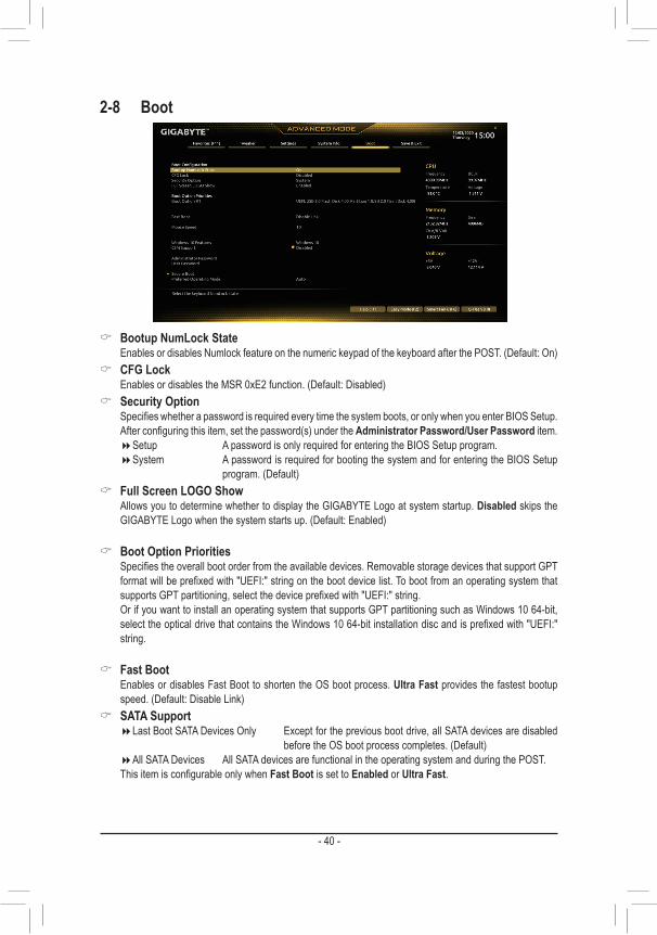
2-8 Boot
& Bootup NumLock State EnablesordisablesNumlockfeatureonthenumerickeypadofthekeyboardafterthePOST.(Default:On)
& CFG Lock EnablesordisablestheMSR0xE2function.(Default:Disabled)
& Security Option Specifieswhetherapasswordisrequiredeverytimethesystemboots,oronlywhenyouenterBIOSSetup.
Afterconfiguringthisitem,setthepassword(s)undertheAdministrator Password/User Password item. �Setup A password is only required for entering the BIOS Setup program. �System A password is required for booting the system and for entering the BIOS Setup
program.(Default) & Full Screen LOGO Show
Allows you to determine whether to display the GIGABYTE Logo at system startup. Disabled skips the GIGABYTELogowhenthesystemstartsup.(Default:Enabled)
& Boot Option Priorities Specifiestheoverallbootorderfromtheavailabledevices.RemovablestoragedevicesthatsupportGPT
formatwillbeprefixedwith"UEFI:"stringonthebootdevicelist.TobootfromanoperatingsystemthatsupportsGPTpartitioning,selectthedeviceprefixedwith"UEFI:"string.
Or if you want to install an operating system that supports GPT partitioning such as Windows 10 64-bit, selecttheopticaldrivethatcontainstheWindows1064-bitinstallationdiscandisprefixedwith"UEFI:"string.
& Fast Boot Enables or disables Fast Boot to shorten the OS boot process. Ultra Fast provides the fastest bootup
speed.(Default:DisableLink) & SATA Support
�LastBootSATADevicesOnly Exceptforthepreviousbootdrive,allSATAdevicesaredisabledbeforetheOSbootprocesscompletes.(Default)
�AllSATADevices AllSATAdevicesarefunctionalintheoperatingsystemandduringthePOST. ThisitemisconfigurableonlywhenFast Boot is set to Enabled or Ultra Fast.
- 40 -
& VGA Support Allows you to select which type of operating system to boot.
�Auto EnableslegacyoptionROMonly. �EFIDriver EnablesEFIoptionROM.(Default)
ThisitemisconfigurableonlywhenFast Boot is set to Enabled or Ultra Fast. & USB Support
�DisableLink All USB devices are disabled before the OS boot process completes. �Full Initial All USB devices are functional in the operating system and during the POST.
(Default) �Partial Initial Part of the USB devices are disabled before the OS boot process completes.
ThisitemisconfigurableonlywhenFast Boot is set to Enabled or Ultra Fast. This function is disabled when Fast Boot is set to Ultra Fast.
& PS2 Devices Support �DisableLink AllPS/2devicesaredisabledbeforetheOSbootprocesscompletes. �Enabled All PS/2 devices are functional in the operating system and during the POST.
(Default) ThisitemisconfigurableonlywhenFast Boot is set to Enabled or Ultra Fast. This function is disabled
when Fast Boot is set to Ultra Fast. & NetWork Stack Driver Support
�DisableLink Disablesbootingfromthenetwork.(Default) �Enabled Enables booting from the network.
ThisitemisconfigurableonlywhenFast Boot is set to Enabled or Ultra Fast. & Next Boot After AC Power Loss
�NormalBoot EnablesnormalbootupuponthereturnoftheACpower.(Default) �Fast Boot Keeps the Fast Boot settings upon the return of the AC power.
ThisitemisconfigurableonlywhenFast Boot is set to Enabled or Ultra Fast.
& Mouse Speed Allowsyoutosetthemousecursormovementspeed.(Default:1X)
& Windows 10 Features Allowsyoutoselecttheoperatingsystemtobeinstalled.(Default:Windows10)
& CSM Support Enables or disables UEFI CSM (Compatibility Support Module) to support a legacy PC boot process.
�Disabled DisablesUEFICSMandsupportsUEFIBIOSbootprocessonly.(Default) �Enabled Enables UEFI CSM.
& LAN PXE Boot Option ROM AllowsyoutoselectwhethertoenablethelegacyoptionROMfortheLANcontroller.(Default:Disabled) ThisitemisconfigurableonlywhenCSM Support is set to Enabled.
& Storage Boot Option Control AllowsyoutoselectwhethertoenabletheUEFIorlegacyoptionROMforthestoragedevicecontroller.
�Donotlaunch DisablesoptionROM. �UEFI EnablesUEFIoptionROMonly. �Legacy EnableslegacyoptionROMonly.(Default)
ThisitemisconfigurableonlywhenCSM Support is set to Enabled.
- 41 -

& Other PCI devices AllowsyoutoselectwhethertoenabletheUEFIorLegacyoptionROMforthePCIdevicecontrollerother
than the LAN, storage device, and graphics controllers. �Donotlaunch DisablesoptionROM. �UEFI EnablesUEFIoptionROMonly.(Default) �Legacy EnableslegacyoptionROMonly.
ThisitemisconfigurableonlywhenCSM Support is set to Enabled.
& Administrator Password Allowsyoutoconfigureanadministratorpassword.Press<Enter>onthisitem,typethepassword,and
thenpress<Enter>.Youwillberequestedtoconfirmthepassword.Typethepasswordagainandpress<Enter>.Youmustentertheadministratorpassword(oruserpassword)atsystemstartupandwhenenteringBIOSSetup.Differingfromtheuserpassword,theadministratorpasswordallowsyoutomakechangestoall BIOS settings.
& User Password Allowsyoutoconfigureauserpassword.Press<Enter>onthisitem,typethepassword,andthenpress
<Enter>.Youwillberequestedtoconfirmthepassword.Typethepasswordagainandpress<Enter>.You must enter the administrator password (or user password) at system startup and when entering BIOS Setup. However, the user password only allows you to make changes to certain BIOS settings but not all.
Tocancelthepassword,press<Enter>onthepassworditemandwhenrequestedforthepassword,enterthecorrectonefirst.Whenpromptedforanewpassword,press<Enter>withoutenteringanypassword.Press<Enter>againwhenpromptedtoconfirm.
NOTE:BeforesettingtheUserPassword,besuretosettheAdministratorPasswordfirst.
� Secure Boot AllowsyoutoenableordisableSecureBootandconfigurerelatedsettings.Thisitemisconfigurableonly
when CSM Support is set to Disabled. & Preferred Operating Mode
Allows you to select whether to enter Easy mode or Advanced mode after entering BIOS Setup. Auto enterstheBIOSmodewhereitwaslasttime.(Default:Auto)
- 42 -

2-9 Save & Exit
& Save & Exit Setup Press<Enter>onthisitemandselectYes. This saves the changes to the CMOS and exits the BIOS Setup
program. Select Noorpress<Esc>toreturntotheBIOSSetupMainMenu. & Exit Without Saving
Press<Enter>onthisitemandselectYes. This exits the BIOS Setup without saving the changes made in BIOS Setup to the CMOS. Select Noorpress<Esc>toreturntotheBIOSSetupMainMenu.
& Load Optimized Defaults Press<Enter>onthisitemandselectYes to load the optimal BIOS default settings. The BIOS defaults
settingshelpthesystemtooperateinoptimumstate.AlwaysloadtheOptimizeddefaultsafterupdatingthe BIOS or after clearing the CMOS values.
& Boot Override Allowsyoutoselectadevicetobootimmediately.Press<Enter>onthedeviceyouselectandselectYes
toconfirm.Yoursystemwillrestartautomaticallyandbootfromthatdevice. & SaveProfiles
ThisfunctionallowsyoutosavethecurrentBIOSsettingstoaprofile.Youcancreateupto8profilesandsaveasSetupProfile1~SetupProfile8.Press<Enter>tocomplete.OryoucanselectSelect File in HDD/FDD/USBtosavetheprofiletoyourstoragedevice.
& LoadProfiles If your system becomes unstable and you have loaded the BIOS default settings, you can use this function
to load theBIOSsettings fromaprofilecreatedbefore,without thehasslesof reconfiguring theBIOSsettings.Firstselecttheprofileyouwishtoloadandthenpress<Enter>tocomplete.YoucanselectSelect File in HDD/FDD/USBtoinputtheprofilepreviouslycreatedfromyourstoragedeviceorloadtheprofileautomatically created by the BIOS, such as reverting the BIOS settings to the last settings that worked properly (last known good record).
- 43 -

Chapter 3 Appendix
Before you begin, please prepare the following items: • AtleasttwoSATAharddrivesorSSDs.(Note 1) (To ensure optimal performance, it is recommended that you use two hard drives with identical model and capacity). (Note 2)
• Windows setup disc. • Motherboard driver disc. • A USB thumb drive.
ConfiguringtheOnboardSATAControllerA. Installing SATA hard drive(s) in your computerInstalltheharddrives/SSDsintheIntel® Chipset controlled connectors on the motherboard. Then connect the power connectors from your power supply to the hard drives.
B.ConfiguringSATAcontrollermodeinBIOSSetupMakesuretoconfiguretheSATAcontrollermodecorrectlyinsystemBIOSSetup.Steps:Turnonyourcomputerandpress<Delete>toenterBIOSSetupduringthePOST(Power-OnSelf-Test).GotoSettings\IOPorts\SATAAndRSTConfiguration, make sure SATA Controller(s)isenabled.TocreateRAID,set SATA Mode Selection to Intel RST Premium With Intel Optane System Acceleration. Then save the settingsandrestartyourcomputer.Note:WhenusingaPCIeSSD,makesuretosettheRST Control PCIe Storage Devices item under Settings\IOPorts\SATAAndRSTConfiguration to Manual. Then depending the M.2 connector you use, set the corresponding PCIe Storage Dev on Port XX item to RST Controlled. Finally, save the settings and exit BIOS Setup.
3-1 ConfiguringaRAIDSetRAID Levels
RAID 0 RAID 1 RAID 5 RAID 10Minimum Number of Hard Drives
≥2 2 ≥3 4
Array CapacityNumber of hard
drives*Sizeofthesmallest drive
Sizeofthesmallestdrive
(Number of hard drives-1)*Sizeofthe smallest drive
(Number of hard drives/2)*Sizeofthe
smallest driveFault Tolerance No Yes Yes Yes
(Note1) AnM.2PCIeSSDcannotbeusedtosetupaRAIDseteitherwithanM.2SATASSDoraSATAharddrive.
(Note2) Referto"InternalConnectors,"fortheinstallationnoticesfortheM.2andSATAconnectors.
C.UEFIRAIDConfigurationSteps:1. After the system reboot, enter BIOS Setup again. Then enter the Settings\IO Ports\Intel(R) Rapid Storage
Technology sub-menu.2. On the Intel(R) Rapid Storage Technologymenu,press<Enter>onCreate RAID Volume to enter the
Create RAID Volume screen. Enter a volume name with 1~16 letters (letters cannot be special characters) under the Nameitemandpress<Enter>.Then,selectaRAIDlevel.RAIDlevelssupportedincludeRAID0, RAID1,RAID10,andRAID5(theselectionsavailabledependonthenumberof theharddrivesbeinginstalled). Next, use the down arrow key to move to Select Disks.
The BIOS Setup menus described in this section may differ from the exact settings for your motherboard. The actual BIOS Setup menu options you will see shall depend on the motherboard you have and the BIOS version.
- 44 -

PleasevisitGIGABYTE'swebsitefordetailsonconfiguringaRAIDarray.
3. Under Select Disksitem,selecttheharddrivestobeincludedintheRAIDarray.Pressthe<Space>keyontheharddrivestobeselected(selectedharddrivesaremarkedwith"X").Thensetthestripeblocksize.Thestripeblocksizecanbesetfrom4KBto128KB.Onceyouhaveselectedthestripeblocksize,setthevolume capacity.
4. After setting the capacity, move to Create Volumeandpress<Enter>tobegin.5. After completing, you'll be brought back to the Intel(R) Rapid Storage Technology screen. Under RAID
VolumesyoucanseethenewRAIDvolume.Toseemoredetailedinformation,press<Enter>onthevolumetocheckforinformationonRAIDlevel,stripeblocksize,arrayname,andarraycapacity,etc.
Install the RAID driver and operating systemWith the correct BIOS settings, you are ready to install the operating system.AssomeoperatingsystemsalreadyincludeRAIDdriver,youdonotneedtoinstallseparateRAIDdriverduringthe Windows installation process. After the operating system is installed, we recommend that you install all requireddriversfromthemotherboarddriverdiscusing"XpressInstall" toensuresystemperformanceandcompatibility.IftheoperatingsystemtobeinstalledrequiresthatyouprovideadditionalRAIDdriverduringtheOS installation process, please refer to the steps below:1. Copy the IRST folder under \Boot in the driver disc to your USB thumb drive.2. Boot from the Windows setup disc and perform standard OS installation steps. When the screen requesting
you to load the driver appears, select Browse.3. ThenbrowsetotheUSBflashdriveandselectthelocationofthedriver.Thelocationofthedriverisas
follows:\IRST\f6flpy-x644. When a screen as shown, select Intel(R) Chipset SATA/PCIe RST Premium Controller and click Next to
load the driver and continue the OS installation.
3-2 Installing Intel® Optane™ Memory and Storage ManagementSteps:1. After entering the operating system, insert the motherboard driver disc into your optical drive. On the Xpress
Install screen, select Intel® Optane™ Memory and Storage Management to install and follow the on-screen instructions to complete the installation. When completed, restart the system.
2. After you install the included motherboard drivers, make sure your Internet connection works properly. The system will automatically install the software from Intel®.Restartthesystemafterthedriverisinstalled.
A. Enabling an Intel® Optane™ MemoryA-1. System Requirements1. Intel® Optane™ memory2. The Optane™ memory must have at least 16 GB capacity, and it must have equal or smaller capacity than
theharddrive/SSDtobeaccelerated.3. The Optane™memorycannotbeusedtoaccelerateanexistingRAIDarray;theacceleratedharddrive/SSD
cannotbeincludedinaRAIDarray.4. Theharddrive/SSDtobeacceleratedmustbeaSATAharddriveorM.2SATASSD.5. Theharddrive/SSDtobeacceleratedcanbeasystemdriveordatadrive.ThesystemdrivemustbeGPT
formatted and have Windows 10 64-bit (or later version) installed on it. The data drive must also be GPT formatted.
6. The motherboard driver disc7. TheSATAcontrollermustsetinIntelRSTPremiumWithIntelOptaneSystemAccelerationmode.
- 45 -

B. Rebuilding an ArrayRebuildingistheprocessofrestoringdatatoaharddrivefromotherdrivesinthearray.Rebuildingappliesonlytofault-tolerantarrayssuchasRAID1,RAID5orRAID10arrays.TheproceduresbelowassumeanewdriveisaddedtoreplaceafaileddrivetorebuildaRAID1array.(Note:Thenewdrivemusthaveequalorgreatercapacity than the old one.)
Turnoffyourcomputerandreplacethefailedharddrivewithanewone.Restartyourcomputer.Whileintheoperating system, launch the Intel® Optane™ Memory and Storage Management utility from the Start menu.
1. Go to the Manage menu and click Rebuild to another disk in Manage Volume.2. SelectanewdrivetorebuildtheRAIDandclickRebuild.3. The Statusitemontherightofthescreendisplaystherebuildprogress.AftertheRAID1volumerebuilding,
the Status will display as Normal.
A-2. Installation Guidelines1. Go to Settings\IOPorts\SATAAndRSTConfiguration and make sure RST Control PCIe Storage
Devices is set to Manual. Then depending on which M.2 connector you install the Optane™ memory in, set the corresponding PCIe Storage Dev on Port XX item to RST Controlled.
2. After re-entering the operating system, launch the Intel® Optane™ Memory and Storage Management application from the Start menu. If you install more than one Optane™ memory, please select which one you are going to use. Then select which drive to be accelerated. Click Enable Intel® Optane™ Memory. All data on the Optane™ memory will be erased. Make sure you back up the data before continuing. Follow the on-screen instructions to proceed. When completed, restart the system.
3. Launch the Intel® Optane™ Memory and Storage Management application from the Start menu and make sure the Intel® Optane™ Memory has been enabled.
4. Ifyouwanttoacceleratethesystemdrive,youcanselectspecificfolders,files,orapplicationstoaccelerateusing the Intel® Optane™ Memory Pinning function. (The Optane™ memory used must have at least 32 GB capacity.)
• An Optane™memorycannotbeusedtoaccelerateanM.2PCIeSSD. • If more than one Optane™ memory is installed, you can select only one of them to accelerate
your SATA-based boot drive. The other(s) can only be used as data drive(s). • DonotabruptlyremovetheOptane™memory.Doingsowillcausetheoperatingsystemtostop
functioning correctly. • If you want to change/remove the Optane™ memory, you must disable it using the Intel® Optane™
Memory and Storage Managementapplicationfirst. • After enabling the Optane™ memory, the related BIOS settings will remain even after a BIOS
update.
- 46 -

• Beforeinstallingthedrivers,firstinstalltheoperatingsystem. • After installing the operating system, insert the motherboard driver disc into your optical drive. Click onthemessage"Taptochoosewhathappenswiththisdisc"onthetop-rightcornerofthescreenandselect"RunRun.exe."(OrgotoMyComputer,double-clicktheopticaldriveandexecutetheRun.exeprogram.)
"XpressInstall"willautomaticallyscanyoursystemandthenlistallofthedriversthatarerecommendedtoinstall. You can click the Xpress Installbuttonand"XpressInstall"willinstallalloftheselecteddrivers.Orclickthe arrow icon to individually install the drivers you need.
3-3 Drivers Installation
Please visit GIGABYTE's website for more software information.
Please visit GIGABYTE's website for more troubleshooting information.
- 47 -
Supplier's Declaration of Conformity47 CFR § 2.1077 Compliance Information
Product Name: MotherboardTrade Name: GIGABYTEModel Number: Z590 GAMING X AX/Z590 GAMING X
Responsible Party – U.S. Contact Information: G.B.T. Inc. Address: 17358 Railroad street, City Of Industry, CA91748Tel.: 1-626-854-9338Internet contact information: https://www.gigabyte.com
FCC Compliance Statement: This device complies with Part 15 of the FCC Rules, Subpart B, Unintentional Radiators. Operation is subject to the following two conditions: (1) This device may not cause harmful interference, and (2) this device must accept any interference received, including interference that may cause undesired operation.
Antenna use:Inorder tocomplywithFCCRFexposure limits, lowgain integratedantennas should be located at a minimum distance of 7.9 inches (20 cm) or more from the body of all persons.
Explosive Device Proximity WarningWarning:Do not operate a portable transmitter (such as awirelessnetwork device) near unshielded blasting caps or in an explosive environmentunless thedevicehasbeenmodified tobequalified forsuch use.
Antenna WarningThe wireless adapter is not designed for use with high-gain antennas.
Use On Aircraft CautionCaution:RegulationsoftheFCCandFAAprohibitairborneoperationofradio-frequency wireless devices because their signals could interfere with critical aircraft instruments.
Other Wireless DevicesSafetyNoticesforOtherDevicesintheWirelessNetwork:Refertothedocumentation supplied with wireless Ethernet adapters or other devices in the wireless network.
Canada, Canada-Industry Notice: This device complies with Industry Canada license-exempt RSSstandard(s). Operation is subject to the following two conditions: (1) this device may not cause interference, and(2) this device must accept any interference, including interference that may cause undesired operation of the device.
Cet appareil est conformeaux normesCanada d’Industrie deRSSpermis-exempt. L’utilisation est assujetti aux deux conditions suivantes: (1) le dispositif ne doit pas produire de brouillage préjudiciable, et
(2) ce dispositif doit accepter tout brouillage reçu, y compris un brouillage susceptible de provoquer un fonctionnement indésirable.
Caution: When using IEEE 802.11a wireless LAN, this product is restricted to indoorusedue to its operation in the5.15-to5.25-GHzfrequency range. Industry Canada requires this product to be used indoorsforthefrequencyrangeof5.15GHzto5.25GHztoreducethepotential for harmful interference to co-channel mobile satellite systems. Highpowerradarisallocatedastheprimaryuserofthe5.25-to5.35-GHzand5.65to5.85-GHzbands.Theseradarstationscancauseinterferencewith and/or damage to this device. The maximum allowed antenna gain forusewiththisdeviceis6dBiinordertocomplywiththeE.I.R.Plimitforthe5.25-to5.35and5.725to5.85GHzfrequencyrangeinpoint-to-pointoperation.TocomplywithRFexposurerequirementsallantennasshouldbe located at a minimum distance of 20cm, or the minimum separation distance allowed by the module approval, from the body of all persons.
Attention:l’utilisationd’unréseausansfilIEEE802.11aestrestreinteàuneutilisationenintérieuràcausedufonctionnementdanslabandedefréquence5.15-5.25GHz.IndustryCanadarequiertqueceproduitsoitutiliséàl’intérieurdesbâtimentspourlabandedefréquence5.15-5.25GHzafinderéduirelespossibilitésd’interférencesnuisiblesauxcanauxco-existants des systèmes de transmission satellites. Les radars de puissances ont fait l’objet d’une allocation primaire de fréquences dans lesbandes5.25-5.35GHzet5.65-5.85GHz.Cesstationsradarpeuventcréer des interférences avec ce produit et/ou lui être nuisible. Le gain d’antenne maximum permissible pour une utilisation avec ce produit estde6dBiafind’êtreconformeauxlimitesdepuissanceisotropiquerayonnéeéquivalente(P.I.R.E.)applicable.danslesbandes5.25-5.35GHzet5.725-5.85GHzenfonctionnementpoint-à-point.Pourseconformerauxconditionsd’expositiondeRFtouteslesantennesdevraientêtrelocaliséesàunedistanceminimumde20cm, ou la distance de séparation minimum permise par l’approbation du module, du corps de toutes les personnes.
Regulatory NoticesUnited States of America, Federal Communications Commission Statement
TheFCCwithitsactioninETDocket96-8hasadoptedasafetystandardforhumanexposuretoradiofrequency(RF)electromagneticenergyemittedbyFCCcertifiedequipment.TheIntelPRO/Wireless5000LANproductsmeettheHumanExposurelimitsfoundinOETBulletin65,2001,and ANSI/IEEE C95.1, 1992. Proper operation of this radio according to the instructions found in this manual will result in exposure substantially below the FCC’s recommended limits.
The following safety precautions should be observed: • Donottouchormoveantennawhiletheunitistransmittingorreceiving. • Donotholdanycomponentcontainingtheradiosuchthattheantennaisverycloseortouchinganyexposedpartsofthebody,especiallythe
face or eyes, while transmitting. • Donotoperatetheradioorattempttotransmitdataunlesstheantennaisconnected;ifnot,theradiomaybedamaged. • Useinspecificenvironments:- Theuseofwirelessdevicesinhazardouslocationsislimitedbytheconstraintsposedbythesafetydirectorsofsuchenvironments.- The use of wireless devices on airplanes is governed by the Federal Aviation Administration (FAA).- The use of wireless devices in hospitals is restricted to the limits set forth by each hospital.
- 48 -

European Union (EU) CE Declaration of ConformityThis device complies with the following directives: Electromagnetic CompatibilityDirective2014/30/EU,Low-voltageDirective2014/35/EU,RadioEquipmentDirective2014/53/EU,ErPDirective2009/125/EC,RoHSdirective (recast) 2011/65/EU & the 2015/863 Statement.This product has been tested and found to comply with all essential requirementsoftheDirectives.
European Union (EU) RoHS (recast) Directive 2011/65/EU & the European Commission Delegated Directive (EU) 2015/863 StatementGIGABYTEproductshavenotintendedtoaddandsafefromhazardoussubstances(Cd,Pb,Hg,Cr+6,PBDE,PBB,DEHP,BBP,DBPandDIBP).ThepartsandcomponentshavebeencarefullyselectedtomeetRoHSrequirement. Moreover, we at GIGABYTE are continuing our efforts to develop products that do not use internationally banned toxic chemicals.
European Union (EU) Community Waste Electrical & Electronic Equipment (WEEE) Directive StatementGIGABYTEwillfulfillthenationallawsasinterpretedfromthe2012/19/EU WEEE (Waste Electrical and Electronic Equipment) (recast) directive. TheWEEEDirective specifies the treatment, collection, recyclinganddisposal of electric and electronic devices and their components. Under theDirective,usedequipmentmustbemarked,collectedseparately,anddisposed of properly.
WEEE Symbol StatementThe symbol shown below is on the product or on its packaging, which indicates that this product must not be disposed of with other waste. Instead, the device should be taken to the waste collection centers for activation of the treatment, collection, recycling and disposal procedure.
For more information about where you can drop off your waste equipment forrecycling,pleasecontactyourlocalgovernmentoffice,yourhouseholdwaste disposal service or where you purchased the product for details of environmentally safe recycling.
End of Life Directives-RecyclingThe symbol shown below is on the product or on its packaging, which indicates that this product must not be disposed of with other waste. Instead, the device should be taken to the waste collection centers for activation of the treatment, collection, recycling and disposal procedure.
Déclaration de Conformité aux Directives de l’Union européenne (UE)Cet appareil portant la marque CE est conforme aux directives de l’UE suivantes: directive Compatibilité Electromagnétique 2014/30/UE, directive Basse Tension 2014/35/UE, directive équipements radioélectriques 2014/53/UE,ladirectiveRoHSII2011/65/UE&ladéclaration2015/863.La conformité à ces directivesest évaluée sur la basedes normeseuropéennes harmonisées applicables.
European Union (EU) CE-KonformitätserklärungDiesesProduktemitCE-KennzeichnungerfüllenfolgendenEU-Richtlinien:EMV-Richtlinie 2014/30/EU,Niederspannungsrichtlinie 2014/35/EU,FunkanlagenRichtlinie2014/53/EU,RoHS-Richtlinie2011/65/EUerfülltund die 2015/863 Erklärung.DieKonformitätmit diesenRichtlinienwird unter Verwendung derentsprechendenStandardszurEuropäischenNormierungbeurteilt.
CE declaração de conformidadeEste produto com a marcação CE estão em conformidade com das seguintesDiretivasUE:DiretivaBaixaTensão2014/35/EU;DiretivaCEM2014/30/EU;DiretivaRSP2011/65/UEeadeclaração2015/863.Aconformidadecomestasdiretivaséverificadautilizandoasnormaseuropeiasharmonizadas.
CE Declaración de conformidadEste producto que llevan la marca CE cumplen con las siguientes DirectivasdelaUniónEuropea:DirectivaEMC2014/30/EU,Directivadebajovoltaje2014/35/EU,Directivadeequipamentosderádio2014/53/EU,DirectivaRoHS2011/65/EUylaDeclaración2015/863.El cumplimiento de estas directivas se evalúa mediante las normas europeasarmonizadas.
CE Dichiarazione di conformitàI prodotti con il marchio CE sono conformi con una o più delle seguenti DirettiveUE,comeapplicabile:DirettivaEMC2014/30/UE,Direttivasullabassatensione2014/35/UE,Direttivadiapparecchiatureradio2014/53/UE,DirettivaRoHS2011/65/EUeDichiarazione2015/863.Laconformità con tali direttive vienevalutatautilizzandogliStandardeuropeiarmonizzatiapplicabili.
DeklaracjazgodnościUEUniiEuropejskiejUrządzenie jest zgodne z następującymi dyrektywami: Dyrektywakompatybilności elektromagnetycznej 2014/30/UE, Dyrektywaniskonapięciowej2014/35/UE,Dyrektywaurządzeńradiowych2014/53/UE,DyrektywaRoHS2011/65/UEidyrektywa2015/863.Niniejszeurządzeniezostałopoddanetestomistwierdzonojegozgodnośćzwymaganiamidyrektywy.
ESProhlášeníoshoděToto zařízení splňuje požadavky Směrnice o Elektromagnetickékompatibilitě 2014/30/EU, Směrnice oNízkém napětí 2014/35/EU,Směrniceorádiovýchzařízeních2014/53/EU,SměrniceRoHS2011/65/EU a 2015/863.Tentoproduktbyltestovánabyloshledáno,žesplňujevšechnyzákladnípožadavkysměrnic.
EKmegfelelőséginyilatkozataA termék megfelelnek az alábbi irányelvek és szabványokkövetelményeinek, azok a kiállításidőpontjában érvényes, aktuálisváltozatában: EMC irányelv 2014/30/EU, Kisfeszültségű villamosberendezésekre vonatkozó irányelv 2014/35/EU, rádióberendezésekirányelv2014/53/EU,RoHSirányelv2011/65/EUés2015/863.
ΔήλωσησυμμόρφωσηςΕΕΕίναι σε συμμόρφωση με τις διατάξεις των παρακάτωΟδηγιώντης Ευρωπαϊκής Κοινότητας:Οδηγία 2014/30/ΕΕ σχετικά με τηνηλεκτρομαγνητικήσυμβατότητα,Οοδηγία χαμηλή τάση2014/35/EU,Οδηγία 2014/53/ΕΕσε ραδιοεξοπλισμό,ΟδηγίαRoHS2011/65/ΕΕκαι2015/863.Ησυμμόρφωσημεαυτέςτιςοδηγίεςαξιολογείταιχρησιμοποιώνταςταισχύονταεναρμονισμέναευρωπαϊκάπρότυπα.
Under Industry Canada regulations, this radio transmitter may only operate using an antenna of a type and maximum (or lesser) gain approved for the transmitter by Industry Canada. To reduce potential radio interference to other users, the antenna type and its gain should be chosen so that the equivalent isotropically radiated power (e.i.r.p.) is not more than that necessary for successful communication.
Conformémentàlaréglementationd'IndustrieCanada,leprésentémetteurradio peut fonctionner avec une antenne d'un type et d'un gain maximal (ou inférieur)approuvépour l'émetteurpar IndustrieCanada.Dans lebutderéduirelesrisquesdebrouillageradioélectriqueàl'intentiondesautres utilisateurs, il faut choisir le type d'antenne et son gain de sorte que la puissance isotrope rayonnée équivalente (p.i.r.e.) ne dépasse pas l'intensiténécessaireàl'établissementd'unecommunicationsatisfaisante.
- 49 -

European Community Directive R&TTE Directive Compliance Statement:
ThisequipmentcomplieswithalltherequirementsandotherrelevantprovisionsofRadioEquipmentDirective2014/53/EU.ThisequipmentissuitableforhomeandofficeuseinalltheEuropeanCommunityMemberStatesandEFTAMemberStates.Thelowband5.15-5.35GHzisforindooruseonly.
AT BE BG CH CY CZ DEDK EE EL ES FI FR HRHU IE IS IT LI LT LULV MT NL PL PT RO SESI SK TR UK
Wireless module manufacturer: Intel® Corporation SASWireless module model name: AX201NGW
Taiwan NCC Wireless Statements / 無線設備警告聲明:低功率電波輻射性電機管理辦法
第十二條: 經型式認證合格之低功率射頻電機,非經許可,公司、商號或使用者均不得擅自變更頻率、加大功率或變更
原設計之特性及功能。
第十四條: 低功率射頻電機之使用不得影響飛航安全及干擾合法通信;經發現有干擾現象時,應立即停用,並改善至無
干擾時方得繼續使用。前項合法通信,指依電信法規定作業之無線電通信。低功率射頻電機須忍受合法通信
或工業、科學及醫療用電波輻射性電機設備之干擾。
在5.25-5.35 秭赫頻帶內操作之無線資訊傳輸設備,限於室內使用。
Korea KCC NCC Wireless Statement:5,25GHz-5,35GHz대역을 사용하는 무선 장치는 실내에서만 사용하도록 제한됩니다。
Japan Wireless Statement:5.15GHz帯~5.35GHz帯: 屋内のみの使用。
Wireless module country approvals:Wireless module manufacturer: Intel® CorporationWireless module model name: AX201NGW
- 50 -

- 51 -

• GIGABYTE eSupportTo submit a technical or non-technical (Sales/Marketing) question, please link to: https://esupport.gigabyte.com
Contact Us
GIGA-BYTE TECHNOLOGY CO., LTD.Address:No.6,BaoqiangRd.,XindianDist.,NewTaipeiCity231,TaiwanTEL: +886-2-8912-4000, FAX: +886-2-8912-4005Tech. and Non-Tech. Support (Sales/Marketing) : https://esupport.gigabyte.comWEB address (English): https://www.gigabyte.comWEB address (Chinese): https://www.gigabyte.com/tw
- 52 -