
GA-WRX80-SU8-IPMI - Gigabyte
53
GA-WRX80-SU8-IPMI User's Manual Rev. 1001
-
Upload
khangminh22 -
Category
Documents
-
view
5 -
download
0
Transcript of GA-WRX80-SU8-IPMI - Gigabyte

GA-WRX80-SU8-IPMI
User's ManualRev. 1001


Copyright© 2021 GIGA-BYTE TECHNOLOGY CO., LTD. All rights reserved.The trademarks mentioned in this manual are legally registered to their respective owners.
DisclaimerInformation in this manual is protected by copyright laws and is the property of GIGABYTE.Changes to the specifications and features in this manual may be made by GIGABYTE without prior notice.No part of this manual may be reproduced, copied, translated, transmitted, or published in any form or by any means without GIGABYTE's prior written permission.For product-related information, check on our website at: https://www.gigabyte.com

- 4 -
Table of ContentsGA-WRX80-SU8-IPMI Motherboard Layout ....................................................................5GA-WRX80-SU8-IPMI Motherboard Block Diagram .......................................................7
Chapter 1 Hardware Installation .....................................................................................81-1 Installation Precautions .................................................................................... 81-2 Product Specifications ...................................................................................... 91-3 Installing the CPU .......................................................................................... 111-4 Installing the Memory ..................................................................................... 121-5 Back Panel Connectors .................................................................................. 131-6 Internal Connectors ........................................................................................ 15
Chapter 2 BIOS Setup ..................................................................................................252-1 Startup Screen ............................................................................................... 252-2 Main ............................................................................................................... 262-3 Advanced ....................................................................................................... 272-4 PBS ................................................................................................................ 332-5 Chipset ........................................................................................................... 342-6 Server Mgmt ................................................................................................... 352-7 Security .......................................................................................................... 382-8 Boot ................................................................................................................ 392-9 Save & Exit ..................................................................................................... 41
Chapter 3 Application....................................................................................................42
Regulatory Notices .................................................................................................... 52Contact Us ................................................................................................................ 53

- 5 -
GA-WRX80-SU8-IPMI Motherboard Layout
1 BMC_VGA
2 BMC_WATCHD
3 COM2
4 SMB_IPMB
5 I_SGPIO1
6 I_SGPIO2
7 TPM
8 SL_CN1/CN2
9 SL_CN3
10 FUSB30_1/2
11 FUSB2
12 F_USB32C
13 USB30V
14 PMBUS
15 CLR_CMOS
16 CI
17 F_PANEL
18 CPU_FAN1
19 SYS_FAN1~6
20 ATX_CPU
21 ATX_PCIE
22 ATX
23 P_X4_M2_A
24 P_X4_M2_B
25 SATA_0_1
26 SATA_2_3
27 BAT
28 F_AUDIO
29 SPEAKER
30 TBT
31 PWR_SW
32 RST_SW
33 QF_SW
34 F_LED1
35 BMC_LED1
28
2
19
10
3
4
5
6
7
11
13
30
17 31 33 2120 221423 192526 8 9
1612
24
18
19
1
29
32
34
35
27
15

- 6 -
Box Contents
5 GA-WRX80-SU8-IPMI motherboard
5 Motherboard driver disc 5 Four SATA cables
5 Quick Installation Guide 5 I/O Shield

GA-WRX80-SU8-IPMI Motherboard Block Diagram
PC
IE U
PLI
NK
PC
IEX
8
- 7 -

Chapter 1 Hardware Installation1-1 Installation PrecautionsThe motherboard contains numerous delicate electronic circuits and components which can become damaged as a result of electrostatic discharge (ESD). Prior to installation, carefully read the user's manual and follow these procedures:
• Prior to installation, make sure the chassis is suitable for the motherboard. • Prior to installation, do not remove or break motherboard S/N (Serial Number) sticker or
warranty sticker provided by your dealer. These stickers are required for warranty validation. • Always remove the AC power by unplugging the power cord from the power outlet before
installing or removing the motherboard or other hardware components. • When connecting hardware components to the internal connectors on the motherboard, make
sure they are connected tightly and securely. • When handling the motherboard, avoid touching any metal leads or connectors. • It is best to wear an electrostatic discharge (ESD) wrist strap when handling electronic
components such as a motherboard, CPU or memory. If you do not have an ESD wrist strap, keep your hands dry and first touch a metal object to eliminate static electricity.
• Prior to installing the motherboard, please have it on top of an antistatic pad or within an electrostatic shielding container.
• Before connecting or unplugging the power supply cable from the motherboard, make sure the power supply has been turned off.
• Before turning on the power, make sure the power supply voltage has been set according to the local voltage standard.
• Before using the product, please verify that all cables and power connectors of your hardware components are connected.
• To prevent damage to the motherboard, do not allow screws to come in contact with the motherboard circuit or its components.
• Make sure there are no leftover screws or metal components placed on the motherboard or within the computer casing.
• Do not place the computer system on an uneven surface. • Do not place the computer system in a high-temperature or wet environment. • Turning on the computer power during the installation process can lead to damage to system
components as well as physical harm to the user. • If you are uncertain about any installation steps or have a problem related to the use of the
product, please consult a certified computer technician. • If you use an adapter, extension power cable, or power strip, ensure to consult with its installation
and/or grounding instructions.
- 8 -

1-2 ProductSpecificationsCPU � AMD Ryzen™ Threadripper™ PRO 3000WX (up to 64C)
� Single sWRX8 4094 socket; CPU TDP supports up to 280W
Chipset � AMD WRX80 Chipset
Memory � 8 x DDR4 DIMM sockets supporting up to 1 TB of system memory � 8 channels memory architecture (1 DIMM per channel) � Support up to DDR4 3200/2933/2600 MHz � Support for UDIMM (ECC), RDIMM, 3DS RDIMM and LRDIMM memory modules � Support system memory capacity up to 1024 GB
Onboard Graphics � 1 x D-Sub port, supporting a maximum resolution of 1920x1200@60 Hz
Audio � Realtek® ALC1220-VB CODEC � High Definition Audio � 2/4/5.1/7.1-channel � Support for S/PDIF Out
LAN � Dual Intel® X550 10 GbE LAN � Dual Intel® i210AT GbE LAN (NCSI MLAN)
Expansion Slots � (Slot7) PCIe x16 (running at Gen 4 x16) � (Slot6) PCIe x16 (running at Gen 4 x16) � (Slot5) PCIe x16 (running at Gen 4 x16) � (Slot4) PCIe x16 (running at Gen 4 x16) � (Slot3) PCIe x16 (running at Gen 4 x16) � (Slot2) PCIe x16 (running at Gen 4 x8) � (Slot1) PCIe x16 (running at Gen 4 x16)
Storage Interface � 4 x SATA 6Gb/s connectors (support for software RAID 0, RAID1, RAID5, and RAID10)
� 2 x M.2 connectors (Socket 3, M key, type 2242/2280, supporting PCIe Gen 4 x4 or SATA mode)
� 2 x slimSAS (PCIe Gen 4 x4 or 4x SATAIII) + 1 x slimSAS (PCIe Gen 4 x4) connectors
USB � 1 x USB Type-C® port on the back panel, with USB 3.2 Gen 2 support � 5 x USB 3.2 Gen 2 Type-A ports (red) on the back panel � 1 x USB Type-C® header onboard, with USB 3.2 Gen 2 support � 2 x USB 3.2 Gen 1 header onboard � 1 x USB 3.2 Gen 1 vertical connector onboard � 1 x USB 2.0 header on board
Internal Connectors
� 1 x 24-pin ATX main power connector � 1 x 8-pin ATX 12V CPU power connector � 1 x 8-pin ATX 12V GPU power connector � 1 x CPU fan header � 6 x system fan headers � 4 x SATA 6Gb/s connectors � 2 x M.2 Socket 3 connectors � 3 x slimSAS connectors � 1 x front panel header � 1 x front panel audio header
- 9 -

Internal Connectors
� 1 x USB Type-C® header, with USB 3.2 Gen 2 support � 1 x USB 3.2 Gen 1 vertical connector � 2 x USB 3.2 Gen 1 header � 1 x USB 2.0 header � 1 x Thunderbolt™ add-in card connector � 1 x Trusted Platform Module(TPM) header (2x6 pin, for the GC-TPM2.0_S
module only) � 1 x serial port header � 1 x chassis intrusion header � 1 x Clear CMOS jumper � 2 x SATA SGPIO headers � 1 x BMC_VGA jumper � 1 x BMC_WATCHD jumper � 1 x SMB_IPMB connector � 1 x PMBUS header � 1 x Speaker
Back Panel Connectors
� 1 x D-sub port � 1 x serial port � 1 x USB 3.2 Gen 2 Type-C port (red) � 5 x USB 3.2 Gen 2 Type-A port (red) � 2 x GbE RJ-45 ports � 2 x 10GbE RJ-45 ports � 1 x optical S/PDIF Out connector � 5 x audio jacks
I/O Controller � ASPEED® AST2500 BMC chip
Hardware Monitor
� Voltage detection � Temperature detection � Fan speed detection � Fan speed control
* Whether the fan speed control function is supported will depend on the fan you install.Operating Properties
� Operating temperature: 10°C to 40°C � Operating humidity: 8 - 80% � Non-operating temperature: -40°C to 70°C � Non-operating humidity: 5% - 95%
Form Factor � CEB Form Factor; 30.5cm x 26.7cm
Operating System
� Windows 10 � Linux
* GIGABYTE reserves the right to make any changes to the product specifications and product-related information without prior notice.
- 10 -

1-3 Installing the CPURead the following guidelines before you begin to install the CPU: • Make sure that the motherboard supports the CPU. • Always turn off the computer and unplug the power cord from the power outlet before installing the
CPU to prevent hardware damage. • Locate the pin one of the CPU. The CPU cannot be inserted if oriented incorrectly. (Or you may
locate the notches on both sides of the CPU and alignment keys on the CPU socket.) • Apply an even and thin layer of thermal grease on the surface of the CPU. • Do not turn on the computer if the CPU cooler is not installed, otherwise overheating and damage
of the CPU may occur. • Set the CPU host frequency in accordance with the CPU specifications. It is not recommended
that the system bus frequency be set beyond hardware specifications since it does not meet the standard requirements for the peripherals. If you wish to set the frequency beyond the standard specifications, please do so according to your hardware specifications including the CPU, graphics card, memory, hard drive, etc.
3
12
1
External cap
2
3CPU
4
5
6 7
1
3
2
8
3
12
4
- 11 -
Installing the CPULocate the alignment keys on the motherboard CPU socket and the notches on the CPU.

Due to CPU limitations, read the following guidelines before installing the memory in 8 Channel mode. � When enabling 8 Channel mode with eight memory modules, it is recommended that memory of the same
capacity, brand, speed, and chips be used.
4ChannelMemoryConfigurationThis motherboard supports 8 Channel Technology. After the memory is installed, the BIOS will automaticallydetect the specifications and capacity of the memory.The eight DDR4 memory sockets are divided into eight channels and each channel has one memory socket as following:
�Channel 1: P1-DIMM_A1 �Channel 2: P1-DIMM_B1 �Channel 3: P1-DIMM_D1 �Channel 4: P1-DIMM_D1 �Channel 5: P1-DIMM_E1 �Channel 6: P1-DIMM_F1 �Channel 7: P1-DIMM_G1 �Channel 8: P1-DIMM_H1
1-4 Installing the MemoryRead the following guidelines before you begin to install the memory: • Make sure that the motherboard supports the memory. It is recommended that memory of the same
capacity, brand, speed, and chips be used.(Go to GIGABYTE's website for the latest supported memory speeds and memory modules.)
• Always turn off the computer and unplug the power cord from the power outlet before installing the memory to prevent hardware damage.
• Memory modules have a foolproof design. A memory module can be installed in only one direction. If you are unable to insert the memory, switch the direction.
- 12 -

1-5 Back Panel Connectors
D-Sub PortThe D-Sub port supports a 15-pin D-Sub connector and supports a maximum resolution of 1920x1200@60 Hz (the actual resolutions supported depend on the monitor being used). Connect a monitor that supports D-Sub connection to this port.COM PortUse this port to connect devices such as a mouse, modem or other peripherals.USB 3.2 Gen 2 Type-A Port (Red)The USB 3.2 Gen 2 Type-A port supports the USB 3.2 Gen 2 specification and is compatible to the USB 3.2 Gen 1 and USB 2.0 specification. Use this port for USB devices.USB Type-C® PortThe reversible USB port supports the USB 3.2 Gen 2x2 specification and is compatible to the USB 3.2 Gen 2, USB 3.2 Gen 1, and USB 2.0 specifications. Use this port for USB devices.GbE LAN Port (LAN1~2)The Gigabit Ethernet LAN port provides Internet connection at up to 1 Gbps data rate. The following describes the states of the LAN port LEDs.
• When removing the cable connected to a back panel connector, first remove the cable from your device and then remove it from the motherboard.
• When removing the cable, pull it straight out from the connector. Do not rock it side to side to prevent an electrical short inside the cable connector.
Link LEDActivity LED
LAN Port
LED State Description
Link (Right)Solid Green 100 Mbps data rateSolid Amber 1 Gbps data rate
Activity (Left) Blinking Yellow Active
Link LEDActivity LED
10 GbE LAN PortThe Gigabit Ethernet LAN port provides Internet connection at up to 10 Gbps data rate. The following describes the states of the LAN port LEDs.
LED State Description
Link (Right)Solid Amber 10 Gbps data rateSolid Green 1 Gbps data rate
Activity (Left) Blinking Yellow Active
Activity LEDLink LED
- 13 -

Center/Subwoofer Speaker OutUse this audio jack to connect center/subwoofer speakers.Rear Speaker OutUse this audio jack to connect rear speakers.Optical S/PDIF Out ConnectorThis connector provides digital audio out to an external audio system that supports digital optical audio. Before using this feature, ensure that your audio system provides an optical digital audio in connector.Line In/Side Speaker OutThe line in jack. Use this audio jack for line in devices such as an optical drive, walkman, etc.Line Out/Front Speaker OutThe line out jack. This jack supports audio amplifying function. For better sound quality, it is recommended that you connect your headphone/speaker to this jack (actual effects may vary by the device being used).Mic InThe Mic in jack.
• If you want to install a Side Speaker, you need to retask the Line in jack to be Side Speaker out through the audio driver.
• To enable or configure the audio amplifying function for the Line out jack, please access the Realtek Audio Console application.
Audio Jack Configurations:
Jack Headphone/ 2-channel 4-channel 5.1-channel 7.1-channel
Center/Subwoofer Speaker Out a a
Rear Speaker Out a a a
Line In/Side Speaker Out a
Line Out/Front Speaker Out a a a a
Mic In a
- 14 -

1-6 Internal Connectors
Read the following guidelines before connecting external devices: • First make sure your devices are compliant with the connectors you wish to connect. • Before installing the devices, be sure to turn off the devices and your computer. Unplug the power
cord from the power outlet to prevent damage to the devices. • After installing the device and before turning on the computer, make sure the device cable has
been securely attached to the connector on the motherboard.
- 15 -
28
2
19
10
3
4
5
6
7
11
13
30
17 31 33 2120 221423 192526 8 9
1612
24
18
19
1
29
32
34
35
27
15
1 BMC_VGA
2 BMC_WATCHD
3 COM2
4 SMB_IPMB
5 I_SGPIO1
6 I_SGPIO2
7 TPM
8 SL_CN1/CN2
9 SL_CN3
10 FUSB30_1/2
11 FUSB2
12 F_USB32C
13 USB30V
14 PMBUS
15 CLR_CMOS
16 CI
17 F_PANEL
18 CPU_FAN1
19 SYS_FAN1~6
20 ATX_CPU
21 ATX_PCIE
22 ATX
23 P_X4_M2_A
24 P_X4_M2_B
25 SATA_0_1
26 SATA_2_3
27 BAT
28 F_AUDIO
29 SPEAKER
30 TBT
31 PWR_SW
32 RST_SW
33 QF_SW
34 F_LED1
35 BMC_LED1

1) BMC_VGA
2) BMC_WATCHD
Pin Definition1-2 Enable (Default)2-3 Disable
Pin Definition1-2 Enable2-3 Disable (Default)
Pin Definition Pin Definition1 NDCD- 2 NSIN3 NSOUT 4 NDTR-5 GND 6 NDSR-7 NRTS- 8 NCTS-9 NRI- 10 -
9
1
10
2
3) COM2 (Serial Port Header)
4) SMB_IPMB
Pin Definition1 SMB_DATA2 GND3 SMB_CLK4 NA
1
- 16 -
1
1
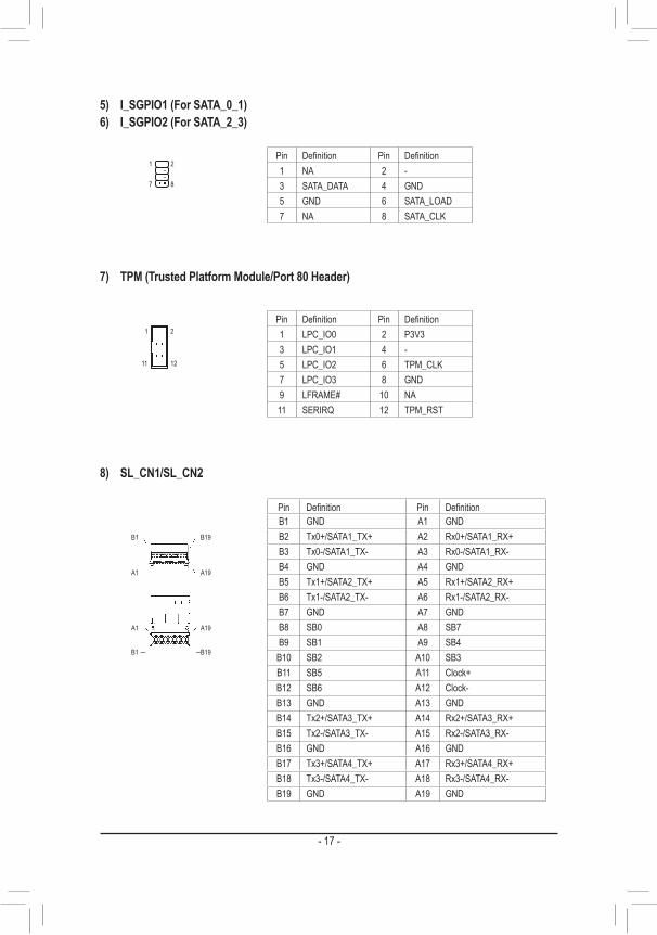
8) SL_CN1/SL_CN2
5) I_SGPIO1 (For SATA_0_1)6) I_SGPIO2 (For SATA_2_3)
Pin Definition Pin Definition1 NA 2 -3 SATA_DATA 4 GND5 GND 6 SATA_LOAD7 NA 8 SATA_CLK
2
8
1
7
7) TPM (Trusted Platform Module/Port 80 Header)
Pin Definition Pin Definition1 LPC_IO0 2 P3V33 LPC_IO1 4 -5 LPC_IO2 6 TPM_CLK7 LPC_IO3 8 GND9 LFRAME# 10 NA11 SERIRQ 12 TPM_RST
2
12
1
11
B19B1
A19A1
A19A1
B19B1
Pin Definition Pin DefinitionB1 GND A1 GNDB2 Tx0+/SATA1_TX+ A2 Rx0+/SATA1_RX+B3 Tx0-/SATA1_TX- A3 Rx0-/SATA1_RX-B4 GND A4 GNDB5 Tx1+/SATA2_TX+ A5 Rx1+/SATA2_RX+B6 Tx1-/SATA2_TX- A6 Rx1-/SATA2_RX-B7 GND A7 GNDB8 SB0 A8 SB7B9 SB1 A9 SB4
B10 SB2 A10 SB3B11 SB5 A11 Clock+B12 SB6 A12 Clock-B13 GND A13 GNDB14 Tx2+/SATA3_TX+ A14 Rx2+/SATA3_RX+B15 Tx2-/SATA3_TX- A15 Rx2-/SATA3_RX-B16 GND A16 GNDB17 Tx3+/SATA4_TX+ A17 Rx3+/SATA4_RX+B18 Tx3-/SATA4_TX- A18 Rx3-/SATA4_RX-B19 GND A19 GND
- 17 -

9) SL_CN3
B19B1
A19A1
A19A1
B19B1
Pin Definition Pin DefinitionB1 GND A1 GNDB2 Tx0+ A2 Rx0+B3 Tx0- A3 Rx0-B4 GND A4 GNDB5 Tx1+ A5 Rx1+B6 Tx1- A6 Rx1-B7 GND A7 GNDB8 SB0 A8 SB7B9 SB1 A9 SB3
B10 SB8 A10 SB9B11 SB2 A11 SB4B12 SB6 A12 SB5B13 GND A13 GNDB14 Tx2+ A14 Rx2+B15 Tx2- A15 Rx2-B16 GND A16 GNDB17 Tx3+ A17 Rx3+B18 Tx3- A18 Rx3-B19 GND A19 GND
10) FUSB30_1/FUSB30_2 (USB 3.2 Gen 1 Headers)
1
10
20
11
Pin Definition Pin Definition1 VBUS 11 D2+2 SSRX1- 12 D2-3 SSRX1+ 13 GND4 GND 14 SSTX2+5 SSTX1- 15 SSTX2-6 SSTX1+ 16 GND7 GND 17 SSRX2+8 D1- 18 SSRX2-9 D1+ 19 VBUS
10 NC 20 -
- 18 -

11) FUSB2 (USB 2.0/1.1 Header)
12) F_USB32C (USB Type-C® Header with USB 3.2 Gen 2 Support)
Pin Definition Pin Definition1 Power (5V) 2 Power (5V)3 USB DX- 4 USB DY-5 USB DX+ 6 USB DY+7 GND 8 GND9 - 10 NC
9
1
10
2
1
10
20
11
Pin Definition Pin Definition1 VBUS 11 VBUS2 TX1+ 12 TX2+3 TX1- 13 TX2-4 GND 14 GND5 RX1+ 15 RX2+6 RX1- 16 RX2-7 VBUS 17 GND8 CC1 18 D-9 SBU1 19 D+
10 SBU2 20 CC2
13) USB30V (USB 3.2 Gen 1 Connector)
Pin Definition1 SMB_CLK2 SMB_DATA3 PSU_ALERT4 GND5 P3V3
1
14) PMBUS (Power supply I2C Connector)
- 19 -

17) F_PANEL
24
23
2
1
Pin Definition Pin Definition1 Power LED+ 2 5V Standby3 - 4 ID LED+5 Power LED- 6 ID LED-7 HDD LED+ 8 System Status LED+9 HDD LED1 10 System Status LED-11 Power Button 12 LAN1 Active LED+13 GND 14 LAN1 Link LED-15 Reset Button 16 SMBus Data17 GND 18 SMBus Clock19 ID Button 20 Case Open21 GND 22 LAN2 Active LED+23 NMI Switch 24 LAN2 Link LED-
Pin Definition1-2 NA (Default)2-3 Clear CMOS
1
15) CLR_CMOS
Pin Definition1 Intrusion Input2 GND
1
16) CI
- 20 -

18) CPU_FAN119) SYS_FAN1~6
Pin Definition1 GND2 P12V3 FAN_TACH4 FAN_PWM
1
20/21) ATX_CPU/ATX_PCIE (2x4, 12V Power Connectors)
ATX_CPU ATX_PCIE
ATX_CPU ATX_PCIE
14
58
ATX_CPU ATX_PCIE
85
41
22) ATX (2x12 Main Power Connector)
2413
121
- 21 -

23/24) P_X4_M2_A/P_X4_M2_B (M.2 Socket 3 Connectors)
P_X4_M2_A
4080
P_X4_M2_B
80
40
25/26) SATA_0_1/SATA_2_3 (SATA 6Gb/s Connectors)
DEBUG PORT
DEBUG PORT
SATA0SATA2
SATA1SATA3
27) BAT
- 22 -

Pin Definition Pin Definition1 MIC2_L 2 GND3 MIC2_R 4 NC5 LINE2_R 6 Sense7 FAUDIO_JD 8 No Pin9 LINE2_L 10 Sense
9
1
10
2
28) F_AUDIO
29) SPEAKER
1 Pin Definition1 5V2 NA3 NA4 SPK-
30) TBT (Thunderbolt™ Pin Header)
1 Pin Definition1 FORCE_POWER2 SCI_EVENT3 SLP_S34 SLP_S45 GND
- 23 -

31) PWR_SW (Power Button)32) RST_SW (Reset Button)33) QF_SW (Q-Flash Plus Button)
PWR_SW QF_SWRST_SW
34) F_LED1 (Onboard Power LED)
State DescriptionSolid Red StandbySolid Green Power On
35) BMC_LED1 (BMC Heartbeat LED)
State DescriptionBlinking Green BMC Normal
- 24 -

Chapter 2 BIOS SetupBIOS (Basic Input and Output System) records hardware parameters of the system in the CMOS on the motherboard. Its major functions include conducting the Power-On Self-Test (POST) during system startup, saving system parameters and loading operating system, etc. BIOS includes a BIOS Setup program that allows the user to modify basic system configuration settings or to activate certain system features.When the power is turned off, the battery on the motherboard supplies the necessary power to the CMOS to keep the configuration values in the CMOS.To access the BIOS Setup program, press the <Delete> key during the POST when the power is turned on.
• Because BIOS flashing is potentially risky, if you do not encounter problems using the current version of BIOS, it is recommended that you not flash the BIOS. To flash the BIOS, do it with caution. Inadequate BIOS flashing may result in system malfunction.
• It is recommended that you not alter the default settings (unless you need to) to prevent system instability or other unexpected results. Inadequately altering the settings may result in system's failure to boot. If this occurs, try to clear the CMOS values and reset the board to default values. (Refer to the "Load Optimized Defaults" section in this chapter or introductions of the battery/clear CMOS jumper in Chapter 1 for how to clear the CMOS values.)
2-1 Startup ScreenThe following startup Logo screen will appear when the computer boots.
- 25 -

2-2 MainOnce you enter the BIOS Setup program, the Main Menu (as shown below) appears on the screen. Use arrow keys to move among the items and press <Enter> to accept or enter a sub-menu.
Main Menu HelpThe on-screen description of a highlighted setup option is displayed on the right of the Main Menu.Submenu HelpWhile in a submenu, press <F1> to display a help screen (General Help) of function keys available for the menu. Press <Esc> to exit the help screen. Help for each item is in the Item Help block on the right side of the submenu.
• When the system is not stable as usual, select the Restore Defaults item to set your system to its defaults. • The BIOS Setup menus described in this chapter are for reference only and may differ by BIOS version.
This section provides information on your motherboard model and BIOS version. You can also select the default language used by the BIOS and manually set the system time.
& System Language Selects the default language used by the BIOS.
& System Date Sets the system date. The date format is week (read-only), month, date, and year. Use <Enter> to switch
between the Month, Date, and Year fields and use the <+> or <-> key to set the desired value. & System Time
Sets the system time. The time format is hour, minute, and second. For example, 1 p.m. is 13:00:00. Use <Enter> to switch between the Hour, Minute, and Second fields and use the <+> or <-> key to set the desired value.
- 26 -

2-3 Advanced
` Trusted Computing(TPM) Enables or disables Trusted Platform Module (TPM).
` AMD fTPM & AMD fTPM switch
Allows you to select the TPM device. Options are: AMD CPU fTPM, OffBoard LPC TPM, OnBoard SPI TPM. (Default: AMD CPU fTPM)
& Erase fTPM NV for factory reset When new CPU is installed, select Enabled to reset fTPM, if you have BitLocker or encryption-enabled
system, the system will no boot without a recovery key. Select Disabled to keep previous fTPM record and continue system boot, fTPM will NOT be enabled with new CPU unless fTPM is reset (reinitialized), you could swap back to the old CPU to recover TPM related keys and data. (Default: Enabled)
` ACPI Settings & EnableACPIAutoConfiguration
Enables or disables BIOS ACPI auto configuration. (Default: Disabled) & Enable Hibernation
Enables or disables system ability to Hibernate (OS/S4 sleep state). This option may not be effective with some operating systems. (Default: Enabled)
& ACPI Sleep State Select the highest ACPI sleep state the system will enter when the suspend button is pressed.
Options are: Suspend Disabled and S3 (Suspend to RAM) (Default).
` Legacy Video Select & On Board/External VGA Select
Specifies the first initiation of the monitor display from the onboard graphics or the external graphics card. (Default: Onboard)
- 27 -

` AST2500SuperIOConfiguration & SerialPort1Configuration(theCOMPortonthebackpanel)
& Serial Port Enables or disables the serial port on the back panel.
& Change Settings Select an optimal settings for Super IO Device. (Default: Auto) Please note that This item is available when Serial Port is set to Enabled.
& SerialPort2Configuration(theonboardCOM2Header) & Serial Port
Enables or disables the onboard serial port. & Change Settings
Select an optimal settings for Super IO Device. (Default: Auto) Please note that This item is available when Serial Port is set to Enabled.
` Serial Port Console Redirection This section allows you to enable/disable serial port console redirection for remote server management
through a serial port.
` CPUConfiguration & SVM Mode
Enables or disables the CPU Virtualization Technology. (Default: Enabled) & SMM Mode
Enables or disables the CPU SMM Lock function. (Default: Enabled) & CPU 0 Information
This item shows the CPU informations.
` IDEConfiguration This section allows you to configure the onboard IDE devices.
` Option ROM Dispatch Policy & Restore if Failure
If system fails to boot and this option is set to Enabled, software will reset settings of this page as well as CSM page to its default values automatically. (Default: Disabled)
& Primary Video Ignore If software will detect that due to the Policy settings, Option ROM of Primary Video Device will not dispatch,
it will ignore this device policy settings, and restore it to Enable automatically. (Default: Enabled) & On Board Display Controller
Enables or disables the onboard display controller. (Default: Enabled) & On Board Network Controller
Enables or disables the onboard network controller. (Default: Enabled) & Slot #1~#12 Empty
Enables or disables Option ROM execution for selected slot. (Default: Enabled)
- 28 -

` PCI Subsystem Settings & Above 4G Decoding
Enables or disables 64-bit capable devices to be decoded in above 4 GB address space (only if your system supports 64-bit PCI decoding). Set to Enabled if more than one advanced graphics card are installed and their drivers are not able to be launched when entering the operating system (because of the limited 4 GB memory address space). (Default: Disabled)
& SR-IOV Support If system has SR-IOV capable PCIe devices, this option enables or disables single root IO Virtualization
support. (Default: Disabled) & BME DMA Mitligation
Re-enable bus master attribute disabled during PCI enumeration for PCI bridges after SMM locked. (Default: Disabled)
& Hot-Plug Support Globally enables or disables hot plug support for the entire system. If system has hot plug capable slots
and this option set to Enabled, it provides a setup screen for selecting PCI resource padding for hot plug. (Default: Enabled)
& I210 LAN1/LAN2, X550 LAN3/LAN4 Globally enables or disables hot plug support for the entire system. If system has hot plug capable slots
and this option set to Enabled, it provides a setup screen for selecting PCI resource padding for hot plug. (Default: Enabled)
` USBConfiguration & Legacy USB Support
Allows USB keyboard/mouse to be used in MS-DOS. (Default: Enabled) & XHCI Hand-off
Determines whether to enable XHCI Hand-off feature for an operating system without XHCI Hand-off support. (Default: Enabled)
& USB Mass Storage Driver Support Enables or disables support for USB storage devices. (Default: Enabled)
& Port 60/64 Emulation Enables or disables emulation of I/O ports 64h and 60h. This should be enabled for full legacy support
for USB keyboards/mice in MS-DOS or in operating system that does not natively support USB devices. (Default: Disabled)
& USB transfer time-out The time-out value for Control, Bulk, and Interrupt transfers. (Default: 20 sec)
& Device reset time-out USB mass storage device Start Unit command time-out. (Default: 20 sec)
& Device power-up delay Maximum time the device will take before it properly reports itself to the Host Controller. Auto uses default
vale: for a Root port it is 100 ms, for a Hub port the delay is taken from Hub descriptor. (Default: Auto) & Mass Storage Devices
Displays a list of connected USB mass storage devices. This item appears only when a USB storage device is installed.
- 29 -

` NetworkStackConfiguration & Network Stack
Disables or enables booting from the network to install a GPT format OS, such as installing the OS from the Windows Deployment Services server. (Default: Enabled)
& IPv4 PXE Support Enables or disables IPv4 PXE Support. This item is configurable only when Network Stack is enabled.
& IPv4 HTTP Support Enables or disables HTTP boot support for IPv4. This item is configurable only when Network Stack is
enabled. & IPv6 PXE Support
Enables or disables IPv6 PXE Support. This item is configurable only when Network Stack is enabled. & IPv6 HTTP Support
Enables or disables HTTP boot support for IPv6. This item is configurable only when Network Stack is enabled.
& PXE boot wait time Allows you to configure how long to wait before you can press <Esc> to abort the PXE boot. This item is
configurable only when Network Stack is enabled. & Media detect count
Allows you to set the number of times to check the presence of media. This item is configurable only when Network Stack is enabled.
` CSMConfiguration & CSM Support
Enables or disables UEFI CSM (Compatibility Support Module) to support a legacy PC boot process. �Enabled Enables UEFI CSM. �Disabled Disables UEFI CSM and supports UEFI BIOS boot process only.
& GateA20 Active �Upon Request GA20 can be disabled using BIOS services. (Default) �Always GA20 cannot be disabled.
This option is useful when any RT code is executed above 1 MB. This item is configurable only when CSM Support is set to Enabled.
& Option ROM Messages Set display mode for Option ROM. Options available: Force BIOS, Keep Current. This item is configurable only when CSM Support is set to Enabled.
& INT19 Trap Response Configures BIOS reaction on INT19 trapping by Option ROM.
�Immediate The system executes the trap right away. �Postponed The system executes the trap during legacy boot.
This item is configurable only when CSM Support is set to Enabled. & Native NVME OPROM Support
Determines NVME OPROM execution policy for devices. This item is configurable only when CSM Support is set to Enabled.
& Bootoptionfilter Controls Legacy/UEFI ROMs priority.
�UEFI and Legacy Disables option ROM. �Legacy only Enables legacy option ROM only. �UEFI only Enables UEFI option ROM only.
This item is configurable only when CSM Support is set to Enabled.
- 30 -

& Network Allows you to select whether to enable the legacy option ROM for the LAN controller.
�Legacy Enables legacy option ROM only. �UEFI Enables UEFI option ROM only.
This item is configurable only when CSM Support is set to Enabled. & Storage
Allows you to select whether to enable the UEFI or legacy option ROM for the storage device controller. �Legacy Enables legacy option ROM only. �UEFI Enables UEFI option ROM only.
This item is configurable only when CSM Support is set to Enabled. & Video
Allows you to select whether to enable the UEFI or Legacy option ROM for the graphics controller. �Legacy Enables legacy option ROM only. �UEFI Enables UEFI option ROM only.
This item is configurable only when CSM Support is set to Enabled. & Other PCI devices
Allows you to select whether to enable the UEFI or Legacy option ROM for the PCI device controller other than the LAN, storage device, and graphics controllers.
�Legacy Enables legacy option ROM only. �UEFI Enables UEFI option ROM only.
This item is configurable only when CSM Support is set to Enabled.
` NVMeConfiguration Displays information on your M.2 NVME PCIe SSD if installed.
` OffboardSATAControllerConfiguration Enables or disables the SATA controllers integrated in the Chipset.
` AMDMemConfigurationStatus Displays memory configuration status.
` RAMDiskConfiguration Press <Enter> to add/remove RAM disks.
` T1sAuthConfiguration Press <Enter> to select T1s Auth Configuration.
` iSCSIConfiguration Configure the iSCSI parameters.
` Intel(R) I210 Gigabit Network Connection This sub-menu provides information on LAN configuration and related configuration options.
` VLANConfiguration Press <Enter> to configure VLAN.
` MACIPv4/IPv6NetworkConfiguration Press <Enter> to configure IPv4/IPv6 network parameters.
- 31 -

` Inter(R) Ethernet Controller X550 Press <Enter> to configure 10 Gigabit Ethernet device parameters.
` Driver Health Provides health status for the drivers/controllers.
- 32 -

2-4 PBS
` AMD Firmware Version The sub-menu displays the information of AMD Firmware.
& NVMe RAID mode Enables or disables the NVMe RAID mode. (Default: Disabled)
& SlimLine PCIE/SATA Switch 1/Switch 2 The signals are auto switched by HW detection. Options are: PCIe, SATA. (Default: PCIe)
& PCIeSlot1Configuration Allows you to configure the PCIEX16_1 slot. Options are: x16 Mode, X4X4X4X4 Mode. (Default: x16 Mode)
& PCIeSlot2Configuration Allows you to configure the PCIEX8_2 slot. Options are: x8 Mode, X4X4 Mode. (Default: x8 Mode)
& PCIeSlot3Configuration Allows you to configure the PCIEX16_3 slot. Options are: x16 Mode, X4X4X4X4 Mode. (Default: x16 Mode)
& PCIeSlot4Configuration Allows you to configure the PCIEX16_4 slot. Options are: x16 Mode, X4X4X4X4 Mode. (Default: x16 Mode)
& PCIeSlot5Configuration Allows you to configure the PCIEX16_5 slot. Options are: x16 Mode, X4X4X4X4 Mode. (Default: x16 Mode)
& PCIeSlot6Configuration Allows you to configure the PCIEX16_6 slot. Options are: x16 Mode, X4X4X4X4 Mode. (Default: x16 Mode)
& PCIeSlot7Configuration Allows you to configure the PCIEX16_7 slot. Options are: x16 Mode, X4X4X4X4 Mode. (Default: x16 Mode)
& Thunderbolt Support Enables or disables the Thunderbolt function. (Default: Disabled)
- 33 -

2-5 Chipset
` South Bridge ` SBUSBConfiguration
This page allows you to configure the SB USB ports. & Rom Armor
Enables or disables Rom Armor.
` North Bridge & Total Memory
Displays the total memory information. ` Socket 0 Information
Displays the information related to Socket 0.
- 34 -

2-6 Server Mgmt
& BMC Support Enables or disables interfaces to communicate with BMC. (Default: Enabled)
& Wait For BMC Allows you to determine whether to wait for BMC response for specified time out. In PILOTII, BMC starts
at the same time when BIOS starts during AC power ON. It takes around 30 seconds to initialize Host to BMC interfaces. (Default: Disabled)
& FRB-2 Timer Enables or disables the FRB-2 Timer. (Default: Enabled)
& FRB-2 Timer timeout Enters value between 1 to 30 minute(s) for FRB-2 Timer Expiration. This item is available when FRB-2
Timer is set to Enabled. & FRB-2 Timer Policy
Configures how the system should respond if the FRB-2 Timer expires. This item is available when FRB-2 Timer is set to Enabled. Options are: Do Nothing (default), Reset, Power Down, and Power Cycle.
& OS Watchdog Timer Enables or disables the OS Watchdog Timer function. (Default: Disabled)
& OS Wtd Timer Timeout Enters value between 1 to 30 minute(s) for OS Boot Watchdog Timer Expiration. This item is available
when OS Watchdog Timer is set to Enabled. & OS Wtd Timer Policy
Configures how the system should respond if the OS Boot Watchdog Timer expires. This item is available when OS Watchdog Timer is set to Enabled. Options are: Do Nothing, Reset (default), Power Down, and Power Cycle.
- 35 -

` System Event Log Press [Enter] to change the SEL event log configuration.
& SEL Components Enables or disables the event logging for error/progress codes during boot. (Default: Enabled)
& Erase SEL Chooses options for erasing SEL. Options are: No (default), Yes, On next reset, Yes, On every reset.
& When SEL is Full Chooses options reactions to a full SEL. Options are: Do nothing (default), Erase Immediately, Delete
Oldest Record. & Log EFI Status Codes
Enables or disables the logging of EFI Status Codes. Options are: Disabled, Both, Error code (default), Progress code.
` View FRU information This page displays the basic system ID information, as well as system product information. Items on this
page are non-configurable.
` Bmc self test log Logs the report returned by BMC self test command.
& Erase Log Selects the options for ease log. Options are: Yes, On every reset (default), No.
& When log if full Selects the action to be taken when log is full. Options are: Clear Log (default), Do not log any more.
` BMCnetworkconfiguration Press [Enter] to configure BMC network parameters.
& ConfigurationAddresssource Selects to configure LAN channel parameters statically or dynamically (by BIOS or BMC). Unspecified
will not modify any BMC network parameters during BIOS phase. Options are: Unspecified (default), Static, DynamicBmcDhcp, DynamicBmcNonDhcp.
& Station IP address Enters IP Address. This item is available when ConfigurationAddresssource is set to Static.
& Subnet mask Enters Subnet mask. This item is available when ConfigurationAddresssource is set to Static.
& Router IP address Enters Router IP address. This item is available when ConfigurationAddresssource is set to Static.
& Router MAC address Enters Router MAC address. This item is available when ConfigurationAddresssource is set to
Static.
& IPv6 Support Enables or disables IPv6 support. (Default: Enabled)
& ConfigurationAddresssource Selects to configure LAN channel parameters statically or dynamically (by BIOS or BMC). Unspecified
will not modify any BMC network parameters during BIOS phase. Options are: Unspecified (default), Static, DynamicBmcDhcp.
& Station IPv6 address Enters IPv6 Address. This item is available when ConfigurationAddresssource is set to Static.
- 36 -

& PrefixLength Changes the prefix length. This item is available when ConfigurationAddresssource is set to Static.
& ConfigurationRouterLan1/Lan2Addresssource Selects to configure LAN channel parameters statically or dynamically (by BIOS or BMC). Unspecified
will not modify any BMC network parameters during BIOS phase. Options are: Unspecified (default), Static, DynamicBmcDhcp.
& IPv6 Router IP Address Changes IPv6 Router1 IP Address. This item is available when ConfigurationRouterLanAddress
source is set to Static. & IPv6RouterPrefixLength
Changes the prefix length. This item is available when ConfigurationRouterLanAddresssource is set to Static.
& IPv6RouterPrefixValue Changes the IPv6 Router prefix value. This item is available when ConfigurationRouterLanAddress
source is set to Static.
` View System Event Log Press [Enter] to view the system event log records.
` BMC User Settings Press [Enter] to add new BMC user.
- 37 -

2-7 Security
& Administrator Password Allows you to configure an administrator password. Press <Enter> on this item, type the password, and
then press <Enter>. You will be requested to confirm the password. Type the password again and press <Enter>. You must enter the administrator password (or user password) at system startup and when entering BIOS Setup. Differing from the user password, the administrator password allows you to make changes to all BIOS settings.
& User Password Allows you to configure a user password. Press <Enter> on this item, type the password, and then press
<Enter>. You will be requested to confirm the password. Type the password again and press <Enter>. You must enter the administrator password (or user password) at system startup and when entering BIOS Setup. However, the user password only allows you to make changes to certain BIOS settings but not all.
To cancel the password, press <Enter> on the password item and when requested for the password, enter the correct one first. When prompted for a new password, press <Enter> without entering any password. Press <Enter> again when prompted to confirm.
NOTE: Before setting the User Password, be sure to set the Administrator Password first.
- 38 -

2-8 Boot
& Setup Prompt Timeout Number of seconds to wait for setup activation key. 65535 (0xFFFF) means indefinite waiting.
& Bootup NumLock State Enables or disables Numlock feature on the numeric keypad of the keyboard after the POST.
& Quiet Boot Allows you to determine whether to display the GIGABYTE Logo at system startup. (Default: Enabled)
& Boot Mode Selects the boot mode. Options are Legacy Only, UEFI without Secure boot, UEFI with Secure boot.
& Boot Option #1/2/3/4/5 Specifies the boot order for a specific device type.
& Fast Boot Enables or disables Fast Boot to shorten the OS boot process. (Default: Enabled)
& SATA Support �Last Boot SATA Devices Only Except for the previous boot drive, all SATA devices are disabled
before the OS boot process completes. (Default) �All SATA Devices All SATA devices are functional in the operating system and during the POST. �HDD Only Except for the previous boot drive, all SATA devices are disabled before the OS
boot process completes. This item is available only when Fast Boot is set to Enabled.
& NVMe Support Allows you to enable or disable NVMe device(s). (Default: Enabled) This item is available only when Fast Boot is set to Enabled.
& VGA Support Allows you to select which type of operating system to boot.
�Auto Enables legacy option ROM only. �EFI Driver Enables EFI option ROM. (Default)
This item is available only when Fast Boot is set to Enabled.
- 39 -

& USB Support �Disabled All USB devices are disabled before the OS boot process completes. �Full Initial All USB devices are functional in the operating system and during the POST.
(Default) �Partial Initial Part of the USB devices are disabled before the OS boot process completes.
This item is available only when Fast Boot is set to Enabled. & PS2 Devices Support
Enables or disables the PS/2 devices be functioned in the operating system and during the POST. This item is available only when Fast Boot is set to Enabled. (Default: Enabled)
& NetWork Stack Driver Support Enables or disables booting from the network. This item is available only when Fast Boot is set to Enabled.
(Default: Disabled) & Redirection Support
Enables or disables Redirection function. This item is available only when Fast Boot is set to Enabled. (Default: Disabled)
- 40 -

2-9 Save & Exit
& Save Changes and Exit Press <Enter> on this item and select Yes. This saves the changes to the CMOS and exits the BIOS Setup
program. Select No or press <Esc> to return to the BIOS Setup Main Menu. & Discard Changes and Exit
Press <Enter> on this item and select Yes. This exits the BIOS Setup without saving the changes made in BIOS Setup to the CMOS. Select No or press <Esc> to return to the BIOS Setup Main Menu.
& Save Changes and Reset Press <Enter> on this item and select Yes to save the changes to the CMOS. Select No or press <Esc>
to return to the BIOS Setup Main Menu. Reboot the system after saving the changes. & Discard Changes and Reset
Press <Enter> on this item and select Yes to cancel the BIOS changes. Select No or press <Esc> to return to the BIOS Setup Main Menu. Reboot the system without saving any changes.
& Save Changes Press <Enter> on this item and select Yes to save the changes to the CMOS. Select No or press <Esc>
to return to the BIOS Setup Main Menu. & Discard Changes
Press <Enter> on this item and select Yes to cancel the BIOS changes. Select No or press <Esc> to return to the BIOS Setup Main Menu.
& Restore Defaults Press <Enter> on this item and select Yes to load the BIOS factory default settings. The BIOS defaults
settings help the system to operate in optimum state. Always load the Optimized defaults after updating the BIOS or after clearing the CMOS values.
& Save as User Defaults Save to current BIOS settings as user-defined default settings.
& Restore User Defaults Load the user-define default settings for all BIOS options.
& Boot Override Allows you to select a device to boot immediately. Press <Enter> on the device you select and select Yes
to confirm. Your system will restart automatically and boot from that device.
- 41 -

Chapter 3 ApplicationBMC WebYou can use the IP from BIOS Setup Manu to connect to BMC Web UI. For example, login to BMC Web using the link https://10.1.9.89.
Login
After entering the IP address into web browser, you can see the login page. You can enter your username and the password (default username is admin, default password is admin), select the language, and then click on the Sign me in button to enter the Web UI.
- 42 -

Dashboard
This page shows the overall monitoring information of the device status. The user warning messages and quick buttons are located at the top right of the Web UI.1. Click on to check notification messages.2. Click on to check warning messages.3. Click on to change language.4. Click on to synchronize with latest sensor status.5. Click on to reload current page.6. Click on to logout.
- 43 -

Sensor
Sensor Details
On this page, details for all the available sensors e.g. Name, Type, Status, Current Reading and Behavior are displayed. Sensor readings are available for Temperature, Fan, Watchdog and Voltage Sensors as well as for supported Discrete Sensors. This page will refresh automatically with the latest data retrieved from the database. Please note that there may be some delay in retrieving this live data. Sensors are organized by their Type and State (Critical, Discrete, Normal and Disabled).
Click on any sensor to view more information about it. For each sensor, thresholds (if supported) and graphical representation of all associated events (read-only) are shown. You can enter the threshold values and click on Save to configure the threshold values. If you select a sensor from the Normal Sensors sections, a Live Widget is also displayed showing its behavior over time.
- 44 -

System Information
This page displays BIOS, CPU, and DIMM Device information list.
FRU Information
This page displays Basic Information, Chassis Information, Board Information, and Product Information for the BMC's FRU devices.FRU Device IDSelect a FRU Device ID from the drop-down list to view the details of the device.FRU Device NameThe device name of the selected FRU will be displayed.
- 45 -
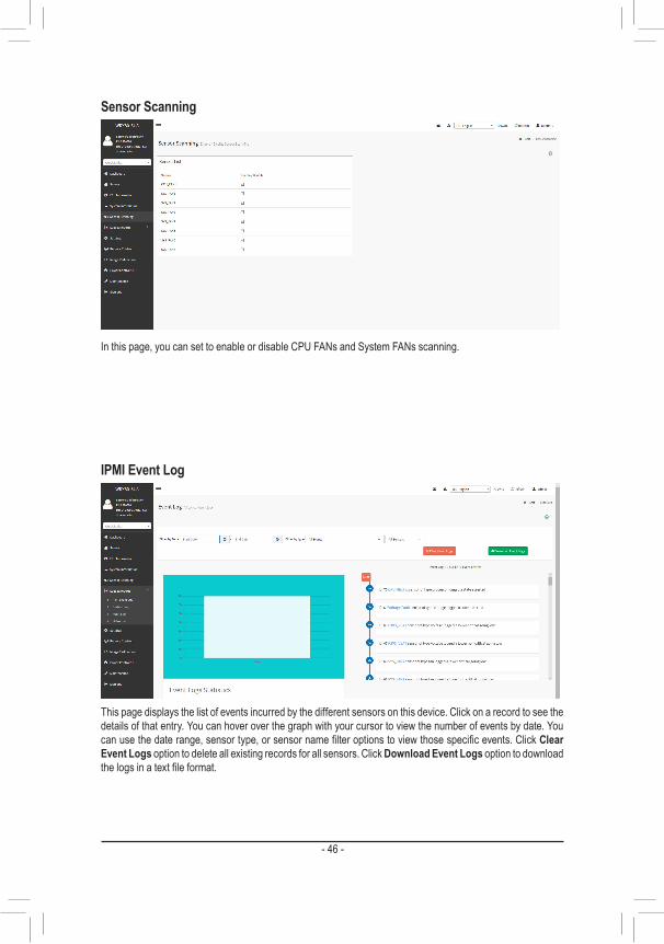
Sensor Scanning
In this page, you can set to enable or disable CPU FANs and System FANs scanning.
IPMI Event Log
This page displays the list of events incurred by the different sensors on this device. Click on a record to see the details of that entry. You can hover over the graph with your cursor to view the number of events by date. You can use the date range, sensor type, or sensor name filter options to view those specific events. Click Clear Event Logs option to delete all existing records for all sensors. Click Download Event Logs option to download the logs in a text file format.
- 46 -

System Log
This page displays logs of system events for this device (if the options have been configured).Note: Logs must be configured under "Settings/Log Settings/Advanced Log Settings" to display any entries. Filtering options are also available for this and all logs in this section.
Audit Log
This page displays audit events for this device (if configured).Note: For configuration, go to "Settings/Log Settings/Advanced Log Settings."
- 47 -
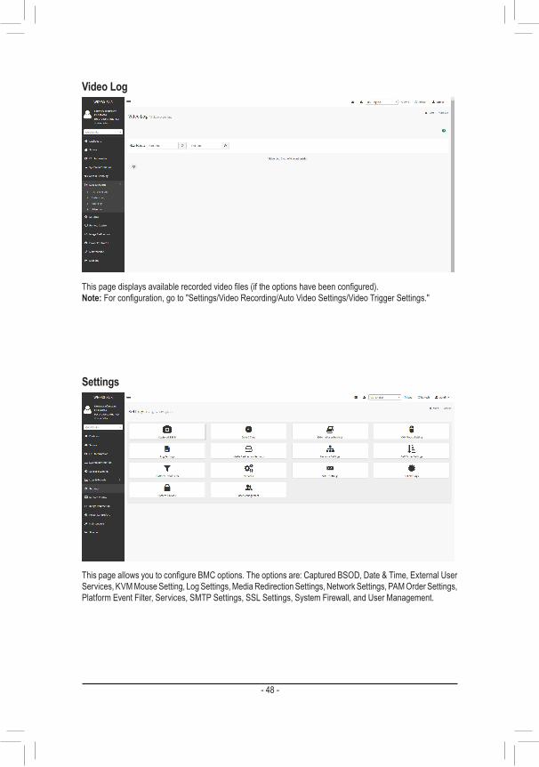
Video Log
This page displays available recorded video files (if the options have been configured).Note: For configuration, go to "Settings/Video Recording/Auto Video Settings/Video Trigger Settings."
Settings
This page allows you to configure BMC options. The options are: Captured BSOD, Date & Time, External User Services, KVM Mouse Setting, Log Settings, Media Redirection Settings, Network Settings, PAM Order Settings, Platform Event Filter, Services, SMTP Settings, SSL Settings, System Firewall, and User Management.
- 48 -

Remote Control
On this page, you can remote control your host system on BIOS Setup or Operating System. Click the Launch H5Viewer button to launch the H5viewer window.
Remote Control- Example (BIOS Setup menu)
This page shows the BIOS Setup settings.
- 49 -

Power Control/UID
On this page, you can remote control the power of your host system. Also, you can turn on/off the UID LED.
Image Redirection
The displayed table shows remote images available to the BMC. You can start redirection or clear the images from here. Up to 4 images can be added for each image type, depending on your configuration.
- 50 -

Maintenance
This page allows you to configure BMC options. The options are Backup Configuration, Firmware Image Location, Firmware Information, Firmware Update, Preserve Configuration, Restore Configuration, Restore Factory Defaults, and System Administrator.
Firmware UpdateBMC Update Procedure:1. Click on Maintenance > Firmware Update from the menu bar.2. Select Update type to BMC and Firmware Image.3. Click on Startfirmwareupdate.4. Click on PreserveallConfigurations. 5. Upload Public Key if needed. 6. Click on Startfirmwareupdate and click on OK from the warning message.7. Verify for section based flashing. Selecting Full Flash is recommended.8. Click on Flash selected sections and OK from the warning message.
BIOS Update Procedure:1. Click on Maintenance > Firmware Update from the menu bar.2. Select Update type to BIOS and Firmware Image.3. Click on Startfirmwareupdate and click on OK from the warning message. 4. Click on Flash BIOS.
- 51 -

Regulatory NoticesUnited States of America, Federal Communications Commission Statement
This equipment has been tested and found to comply with the limits for a Class B digital device, pursuant to Part 15 of the FCC Rules. These limits are designed to provide reasonable protection against harmful interference in a residential installation. This equipment generates, uses and can radiate radio frequency energy and, if not installed and used in accordance with manufacturer's instructions, may cause harmful interference to radio communications. However, there is no guarantee that interference will not occur in a particular installation. If this equipment does cause harmful interference to radio or television reception, which can be determined by turning the equipment off and on, the user is encouraged to try to correct the interference by one or more of the following measures: • Reorient or relocate the receiving antenna. • Increase the separation between the equipment and receiver. • Connect the equipment to an outlet on a circuit different from that to
which the receiver is connected. • Consult the dealer or an experienced radio/TV technician for help.
Canadian Department of Communications StatementThis digital apparatus does not exceed the Class B limits for radio noise emissions from digital apparatus set out in the Radio Interference Regulations of the Canadian Department of Communications. This class B digital apparatus complies with Canadian ICES-003.
Avis de conformité à la réglementation d'Industrie CanadaCet appareil numérique de la classe B est conforme à la norme NMB-003 du Canada.
European Union (EU) CE Declaration of ConformityThis device complies with the following directives: Electromagnetic Compatibility Directive 2014/30/EU, Low-voltage Directive 2014/35/EU, RoHS directive (recast) 2011/65/EU & the 2015/863 Statement. This product has been tested and found to comply with all essential requirements of the Directives.
European Union (EU) RoHS (recast) Directive 2011/65/EU & the European Commission Delegated Directive (EU) 2015/863 StatementGIGABYTE products have not intended to add and safe from hazardous substances (Cd, Pb, Hg, Cr+6, PBDE, PBB, DEHP, BBP, DBP and DIBP). The parts and components have been carefully selected to meet RoHS requirement. Moreover, we at GIGABYTE are continuing our efforts to develop products that do not use internationally banned toxic chemicals.
European Union (EU) Community Waste Electrical & Electronic Equipment (WEEE) Directive StatementGIGABYTE will fulfill the national laws as interpreted from the 2012/19/EU WEEE (Waste Electrical and Electronic Equipment) (recast) directive. The WEEE Directive specifies the treatment, collection, recycling and disposal of electric and electronic devices and their components. Under the Directive, used equipment must be marked, collected separately, and disposed of properly.
WEEE Symbol StatementThe symbol shown below is on the product or on its packaging, which indicates that this product must not be disposed of with other waste. Instead, the device should be taken to the waste collection centers for activation of the treatment, collection, recycling and disposal procedure.
For more information about where you can drop off your waste equipment for recycling, please contact your local government office, your household waste disposal service or where you purchased the product for details of environmentally safe recycling.
End of Life Directives-RecyclingThe symbol shown below is on the product or on its packaging, which indicates that this product must not be disposed of with other waste. Instead, the device should be taken to the waste collection centers for activation of the treatment, collection, recycling and disposal procedure.
Déclaration de Conformité aux Directives de l'Union européenne (UE)Cet appareil portant la marque CE est conforme aux directives de l'UE suivantes: directive Compatibilité Electromagnétique 2014/30/UE, directive Basse Tension 2014/35/UE et directive RoHS II 2011/65/UE. La conformité à ces directives est évaluée sur la base des normes européennes harmonisées applicables.
European Union (EU) CE-KonformitätserklärungDieses Produkte mit CE-Kennzeichnung erfüllen folgenden EU-Richtlinien: EMV-Richtlinie 2014/30/EU, Niederspannungsrichtlinie 2014/30/EU und RoHS-Richtlinie 2011/65/EU erfüllt. Die Konformität mit diesen Richtlinien wird unter Verwendung der entsprechenden Standards zurEuropäischen Normierung beurteilt.
CE declaração de conformidadeEste produto com a marcação CE estão em conformidade com das seguintes Diretivas UE: Diretiva Baixa Tensão 2014/35/EU; Diretiva CEM 2014/30/EU; Diretiva RSP 2011/65/UE. A conformidade com estas diretivas é verificada utilizando as normas europeias harmonizadas.
CE Declaración de conformidadEste producto que llevan la marca CE cumplen con las siguientes Directivas de la Unión Europea: Directiva EMC (2014/30/EU), Directiva de bajo voltaje (2014/35/EU), Directiva RoHS (recast) (2011/65/EU). El cumplimiento de estas directivas se evalúa mediante las normas europeas armonizadas.
Dichiarazione di conformità CEQuesto prodotto è conforme alle seguenti direttive: Direttiva sulla compatibilità elettromagnetica 2014/30/UE, Direttiva sulla bassa tensione 2014/35/UE, Direttiva RoHS (rifusione) 2011/65/UE. Questo prodotto è stato testato e trovato conforme a tutti i requisiti essenziali delle Direttive.
Supplier's Declaration of Conformity47 CFR § 2.1077 Compliance Information
Product Name: MotherboardTrade Name: GIGABYTEModel Number: GA-WRX80-SU8-IPMI
Responsible Party – U.S. Contact Information: G.B.T. Inc. Address: 17358 Railroad street, City Of Industry, CA91748Tel.: 1-626-854-9338Internet contact information: https://www.gigabyte.com
FCC Compliance Statement: This device complies with Part 15 of the FCC Rules, Subpart B, Unintentional Radiators. Operation is subject to the following two conditions: (1) This device may not cause harmful interference, and (2) this device must accept any interference received, including interference that may cause undesired operation.
- 52 -

Contact Us
GIGA-BYTE TECHNOLOGY CO., LTD.Address: No.6, Baoqiang Rd., Xindian Dist., New Taipei City 231, TaiwanTEL: +886-2-8912-4000, FAX: +886-2-8912-4005Tech. and Non-Tech. Support (Sales/Marketing) : https://esupport.gigabyte.comWEB address (English): https://www.gigabyte.comWEB address (Chinese): https://www.gigabyte.com/tw
• GIGABYTE eSupportTo submit a technical or non-technical (Sales/Marketing) question, please link to: https://esupport.gigabyte.com
- 53 -