MX32-4L0 - Gigabyte
83
MX32-4L0 Intel ® Socket LGA1151 processor motherboard User Manual Rev. 2.0
-
Upload
khangminh22 -
Category
Documents
-
view
1 -
download
0
Transcript of MX32-4L0 - Gigabyte

MX32-4L0Intel® Socket LGA1151 processor motherboard
User ManualRev. 2.0

Copyright© 2019 GIGA-BYTE TECHNOLOGY CO., LTD. All rights reserved.The trademarks mentioned in this manual are legally registered to their respective owners.
DisclaimerInformation in this manual is protected by copyright laws and is the property of GIGABYTE. Changes to the specifications and features in this manual may be made by GIGABYTE without prior notice. No part of this manual may be reproduced, copied, translated, transmitted, or published in any form or by any means without GIGABYTE's prior written permission.
Documentation ClassificationsIn order to assist in the use of this product, GIGABYTE provides the following types of documentation: UserManual:detailedinformation&stepsabouttheinstallation,configurationandusethis product (e.g. motherboard, server barebones), covering hardware and BIOS. User Guide: detailed information about the installation & use of an add-on hardware or softwarecomponent(e.g.BMCfirmware,rail-kit)compatiblewiththisproduct. Quick Installation Guide: a short guide with visual diagrams that you can reference easily for installation purposes of this product (e.g. motherboard, server barebones).Please see the support section of the online product page to check the current availability of these documents
For More InformationForrelatedproductspecifications,thelatestfirmwareandsoftware,andotherinformation,pleasevisitour website at: http://www.gigabyte.com.
For GIGABYTE distributors and resellers, additional sales & marketing materials are available from our reseller portal: http://reseller.b2b.gigabyte.com
For further technical assistance, please contact your GIGABYTE representative or visit http://esupport.gigabyte.com/ to create a new support ticket.
For any general sales or marketing enquires, you may message GIGABYTE server directly by email: [email protected].

- 3 -
Table of Contents
MX32-4L0 Motherboard Layout .......................................................................................5Block Diagram .................................................................................................................7Chapter 1 Hardware Installation .....................................................................................8
1-1 Installation Precautions .................................................................................... 81-2 ProductSpecifications ...................................................................................... 91-3 Installing the CPU and CPU Cooler ............................................................... 11
1-3-1 Installing the CPU ...................................................................................................111-3-2 Installing the CPU Cooler .......................................................................................13
1-4 Installing the Memory ..................................................................................... 141-4-1 Installing a Memory ...............................................................................................14
1-5 Installing the M.2 SSD Module ....................................................................... 151-6 Back Panel Connectors .................................................................................. 161-7 Internal Connectors ........................................................................................ 171-8 Jumper Settings ............................................................................................. 26
Chapter 2 BIOS Setup ..................................................................................................272-1 The Main Menu .............................................................................................. 292-2 Advanced Menu ............................................................................................. 32
2-2-1 CPUConfiguration ..................................................................................................332-2-2 PCI Subsystem Settings .........................................................................................342-2-3 Power & Performance Settings ..............................................................................352-2-4 ServerMEConfiguration ........................................................................................382-2-5 Trusted Computing .................................................................................................392-2-6 Serial Port Console Redirection .............................................................................402-2-7 AST2500SuperIOConfiguration ...........................................................................432-2-8 NetworkStackConfiguration ..................................................................................452-2-9 USBConfiguration ..................................................................................................462-2-10 Runtime Error Logging Settings .............................................................................472-2-11 S5 RTC Wake Settings ...........................................................................................482-2-12 NVMeConfiguration ...............................................................................................492-2-13 OffBoardSATAControllerConfiguration .................................................................502-2-14 ChipsetConfiguration .............................................................................................512-2-15 iSCSIConfiguration ................................................................................................522-2-16 Intel(R) I210 Gigabit Network Connection ..............................................................532-2-17 VLANConfiguration ................................................................................................562-2-18 Driver Health ...........................................................................................................58
2-3 Chipset Setup Menu ....................................................................................... 59

- 4 -
2-3-1 SyetemAgent(SA)Configuration ...........................................................................602-3-2 PCH-IOConfiguration ............................................................................................61
2-4 Server Management Menu ............................................................................. 622-4-1 System Event Log ..................................................................................................642-4-2 View FRU Information ............................................................................................652-4-3 BMCNetworkConfiguration ...................................................................................662-4-4 IPv6BMCNetworkConfiguration ...........................................................................67
2-5 Security Menu ................................................................................................ 682-5-1 Secure Boot ...........................................................................................................69
2-6 Boot Menu ...................................................................................................... 712-6-1 UEFI NETWORK Drive BBS Priorities ..................................................................732-6-2 UEFI Application Boot Priorities ................................................................... 74
2-7 Save & Exit Menu ........................................................................................... 752-8 BIOS POST Codes ........................................................................................ 77
2-8-1 AMI Standard - PEI .................................................................................................772-8-2 AMI Standard - DXE ...............................................................................................772-8-3 AMI Standard - ERROR .........................................................................................792-8-4 Intel UPI POST Codes ............................................................................................802-8-5 Intel UPI Error Codes .............................................................................................802-8-6 Intel MRC POST Codes .........................................................................................812-8-7 Intel MRC Error Codes ...........................................................................................812-8-8 Intel PM POST Codes ............................................................................................822-8-9 Intel PM POST Codes ............................................................................................82
2-9 BIOS POST Beep code (AMI standard) ......................................................... 832-9-1 PEI Beep Codes .....................................................................................................832-9-2 DXE Beep Codes ...................................................................................................83

- 5 -
MX32-4L0 Motherboard Layout
DIMM_P
0_A1
DIMM_P
0_A0
DIMM_P
0_B1
DIMM_P
0_B0
CPU
1 2 3 4 5 6
7
8
910111214 13151617181920
2122
2324
25
26
27
28
29
30
3132
33
34
35
36 37
38

- 6 -
Item Code Description1 SW_ID ID button with LED2 USB3_MLAN Server management LAN port (top)/ USB3.0 ports (bottom)3 LAN1_2 GbE Ethernet LAN port #1 (top) / #2 (bottom)4 LAN3_4 GbE Ethernet LAN port #3 (top) / #4 (bottom)5 P2 8 pin power connector (for CPU, DDR)6 COM1_VGA Serial port (top)/VGA port (bottom)7 PMBUS PMBus connector8 SYS_FAN1 System fan connector #19 SYS_FAN3 System fan connector #3
10 SYS_FAN2 System fan connector #211 P1 24 pin main power connector12 SYS_FAN4 System fan connector #413 CPU_FAN CPU fan connector14 SATA_SGP1 SATA SGPIO connector #115 BAT Battery socket16 SATA_0_1 SATA III 6Gb/s connector17 SATA_2_3 SATA III 6Gb/s connector18 SATA_SGP2 SATA SGPIO connector #219 SATA_DOM2 SATA port 4 DOM power connector20 SATA_DOM1 SATA port 5 DOM power connector21 SATA4 SATA III 6Gb/s connector (Support SATA DOM power)22 SATA5 SATA III 6Gb/s connector (Support SATA DOM power)23 SATA6 SATA III 6Gb/s connector24 SATA7 SATA III 6Gb/s connector25 USB_A1 Type A USB 2.0 connector26 F_USB3 USB 3.0 connector27 FP_1 Front panel header28 TPM TPM module connector29 M2_MKEY M.2 slot (PCIe Gen3 x4, Support NGFF-2280, M-Key)30 F_USB2 USB 2.0 connector31 IPMB IPMB connector32 LAN3_ACT LAN port #3 active LED header33 LAN4_ACT LAN port #4 active LED header34 BP_1 HDD back plane board header35 COM2 Serial port cable connector36 PCIE_4 PCI Express x8 slot (Gen3 x4 Signal)37 PCIE_6 PCI Express x16 slot38 LED_BMC BMCfirmwarereadinessLED

- 7 -
Block Diagram

Hardware Installation - 8 -
1-1 Installation PrecautionsThe motherboard contains numerous delicate electronic circuits and components which can become damaged as a result of electrostatic discharge (ESD). Prior to installation, carefully read the user's manual and follow these procedures: • Prior to installation, do not remove or break motherboard S/N (Serial Number) sticker or
warranty sticker provided by your dealer. These stickers are required for warranty validation. • Always remove the AC power by unplugging the power cord from the power outlet before
installing or removing the motherboard or other hardware components. • When connecting hardware components to the internal connectors on the motherboard,
make sure they are connected tightly and securely. • When handling the motherboard, avoid touching any metal leads or connectors. • It is best to wear an electrostatic discharge (ESD) wrist strap when handling electronic
components such as a motherboard, CPU or memory. If you do not have an ESD wrist strap,keepyourhandsdryandfirsttouchametalobjecttoeliminatestaticelectricity.
• Prior to installing the motherboard, please have it on top of an antistatic pad or within an electrostatic shielding container.
• Before unplugging the power supply cable from the motherboard, make sure the power supply has been turned off.
• Before turning on the power, make sure the power supply voltage has been set according to the local voltage standard.
• Before using the product, please verify that all cables and power connectors of your hardware components are connected.
• To prevent damage to the motherboard, do not allow screws to come in contact with the motherboard circuit or its components.
• Make sure there are no leftover screws or metal components placed on the motherboard or within the computer casing.
• Do not place the computer system on an uneven surface. • Do not place the computer system in a high-temperature environment. • Turning on the computer power during the installation process can lead to damage to
system components as well as physical harm to the user. • If you are uncertain about any installation steps or have a problem related to the use of the
product,pleaseconsultacertifiedcomputertechnician.
Chapter 1 Hardware Installation

- 9 - Hardware Installation
1-2 ProductSpecificationsCPU � Intel® Xeon® Processor E-2100/ E-2200 series
� 8th Gen. Intel Core™ i3/ Pentium®/ Celeron® Processors
Chipset � Intel® C246 Express Chipset
Memory � 4 x DIMM slots � Dual channel memory architecture � Supports 1.2V DDR4 memory � ECC UDIMM modules supported; Up to 64GB � Supported speeds: 2666/2400 MHz
Onboard Graphics
� Integrated in Aspeed® AST2500 � 2D Video Graphic Adapter with PCIe bus interface � 1920x1200@60Hz 32bpp, DDR4 SDRAM
LAN � 4 x GbE LAN ports (Intel® I210) � 1 x 10/100/1000 management LAN
Expansion Slots � 1 x PCI Express x16 slot; running at Gen3 x16 � 1 x PCI Express x8 slot; running at Gen3 x4 � 1 x M.2 slot:
- M-key- PCIe Gen3 x4 per slot- Supports NGFF-2280/2260/2242 cards- Intel® Optane™ Memory Ready
Storage Interface � 8 x SATA III 6Gb/s connectors � SATA4/ SATA5 support SATA DOM
RAID � Intel® SATA RAID 0/1/10/5Internal I/O Connectors
� 1 x 24-pin ATX main power connector � 1 x 8-pin ATX 12V power connector � 8 x SATA III 6Gb/s ports � 1 x M.2 slot � 1 x USB 2.0 vertical port � 1 x CPU fan header � 4 x System fan headers � 1 x USB 3.0 header � 1 x USB 2.0 header � 1 x COM port header � 1 x Back panel header � 1 x TPM header � 2 x SATA SGPIO headers � 2 x SATA DOM headers � 1 x Front panel header � 1 x JTAG BMC header � 1 x Case Open � 1 x Chassis Intrusion header � 1 x IPMB connector � 1 x PMBus connector

Hardware Installation - 10 -
Rear I/O Connectors
� 1 x Serial port � 1 x VGA port � 4 x RJ45 ports � 1 x MLAN port � 2 x USB 3.0 ports � 1 x ID switch
TPM � 1 x TPM header
Board Management
� Aspeed® AST2500 management controller � AMI MegaRAC SP-X Solution Web interface
Form Factor � microATX � 244mm W x 244mm D
GIGABYTE reserves the right tomakeany changes to theproduct specificationsandproduct-relatedinformation without prior notice.
- 11 - Hardware Installation
1-3 Installing the CPU and CPU Cooler
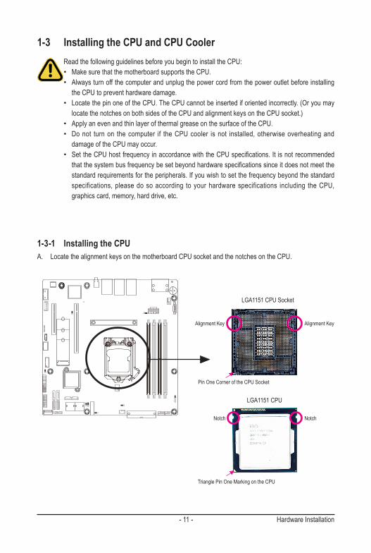
1-3-1 Installing the CPUA. Locate the alignment keys on the motherboard CPU socket and the notches on the CPU.
Read the following guidelines before you begin to install the CPU: • Make sure that the motherboard supports the CPU.• Always turn off the computer and unplug the power cord from the power outlet before installing
the CPU to prevent hardware damage.• Locate the pin one of the CPU. The CPU cannot be inserted if oriented incorrectly. (Or you may
locate the notches on both sides of the CPU and alignment keys on the CPU socket.)• Apply an even and thin layer of thermal grease on the surface of the CPU.• Do not turn on the computer if the CPU cooler is not installed, otherwise overheating and
damage of the CPU may occur.• SettheCPUhostfrequencyinaccordancewiththeCPUspecifications.Itisnotrecommended
thatthesystembusfrequencybesetbeyondhardwarespecificationssinceitdoesnotmeetthestandard requirements for the peripherals. If you wish to set the frequency beyond the standard specifications, please do so according to your hardware specifications including the CPU, graphics card, memory, hard drive, etc.
Notch
Alignment KeyAlignment Key
Notch
LGA1151 CPU
LGA1151 CPU Socket
Pin One Corner of the CPU Socket
Triangle Pin One Marking on the CPU

Hardware Installation - 12 -
Step 1: Gently press the CPU socket lever handle down andawayfromthesocketwithyourfinger.Thencompletely lift the CPU socket lever and the metal load plate will be lifted as well.
Step 3: HoldtheCPUwithyourthumbandindexfingers.Align the CPU pin one (triangle marking) with the pin one corner of the CPU socket (or you may align the CPU notches with the socket alignment keys). Gently insert the CPU into position.
Step 5: Push the CPU socket lever back into its locked position.
Step 4: Once the CPU is properly inserted, use one hand to hold the socket lever and use the other to lightly replace the load plate. When replacing the load plate, make sure the front end of the load plate is under the shoulder screw.
NOTE:Hold the CPU socket lever by the handle, not by the lever base position.
Step 2: Remove the CPU socket cover as shown. Hold your index finger down on the rear grip of the socket cover and use your thumb to lift up the front edge (next to the "REMOVE" mark) and then remove the cover. (DO NOT touch socket contacts. To protect the CPU socket, always replace the protective socket cover when the CPU is not installed.)
B. Follow the steps below to correctly install the CPU into the motherboard CPU socket.
Before installing the CPU, make sure to turn off the computer and unplug the power cord from the power outlet power plug to prevent any damage to prevent damage to the CPU.

- 13 - Hardware Installation
1-3-2 Installing the CPU CoolerFollow the steps below to correctly install the CPU cooler on the motherboard. (The following procedure uses Intel® boxed cooler as the example cooler.)
Use extreme care when removing the CPU cooler because the thermal grease/tape between the CPU cooler and CPU may adhere to the CPU. Inadequately removing the CPU cooler may damage the CPU.
Step 1:Apply a thin, even layer of thermal paste onto the surface of the installed CPU.
Male Push Pin
Female Push Pin
The Top of Female Push Pin
Direction of the Arrow Sign on the Male Push Pin
Step 2:Before installing the cooler, note the direction of the arrow sign on the male push pin. (Turning the push pin along the direction of the arrow is for removing the cooler, and the opposite direction is for installing it.)
Step 3: Place the cooler atop the CPU, aligning the four push pins through the pin holes on the motherboard. Push down on the push pins diagonally.
Step 4:You should hear a "click" when pushing down each push pin. Check that the Male and Female pushpinsarejoinedclosely.(RefertoyourCPUcooler installation manual for instructions on installing the cooler.)
Step 5: After the installation, check the back of the motherboard. If the push pin is inserted as the picture above shows, the installation is complete.
Step 6: Finally, attach the power connector of the CPU cooler to the CPU fan header (CPU_FAN) on the motherboard.

Hardware Installation - 14 -
1-4 Installing the MemoryRead the following guidelines before you begin to install the memory:• Make sure that the motherboard supports the memory. It is recommended to use memory of the
same capacity, brand, speed, and chips.• Always turn off the computer and unplug the power cord from the power outlet before installing
the memory to prevent hardware damage.• Memory modules have a foolproof design. A memory module can be installed in only one
direction. If you are unable to insert the memory, switch the direction.
1-4-1 Installing a Memory Before installing a memory module, make sure to turn off the computer and unplug the power cord from the power outlet to prevent damage to the memory module.Be sure to install DDR4 UDIMMs on this motherboard.
Installation Step:Step 1. Insert the UDIMM memory module vertically into the UDIMM slot, and push it down.Step 2. Close the plastic clip at both edges of the UDIMM slots to lock the UDIMM module.Note: For dual-channel operation, UDIMMs must be installed in matched pairs.Step 3. Reverse the installation steps when you wish to remove the UDIMM module.
12
2
TypeRanks Per DIMM
and Data Width
Supported
Voltage
Speed (MT/s);
Slot Per Channel(SPC) and
DIMM Per Channel (DPC)
2 Slot Per Channel
1DPC 2DPC
UDIMM Unbuffered
DDR4 ECCSR, DR 1.2V 2133/ 2400/ 2666 2133/ 2400/ 2666
UDIMM Unbuffered
DDR4 non-ECCSR, DR 1.2V 2133/ 2400/ 2666 2133/ 2400/ 2666
• All channels in system run at the fastest common frequency.• Mixing ECC and non-ECC UDIMMs anywhere on the platform is not supported.• UDIMM 2666 two DIMMs per channel (2DPC) is supported when channel is populated with the same UDIMM memory module.

- 15 - Hardware Installation
1-5 Installing the M.2 SSD ModuleFollow the steps below to install a M.2 SSD module on your motherboard.
Step1. Insert the M.2 SSD module into the slot.Step2. Secure it with the screw, tightening as necessary to fasten the M.2 SSD module in place.
2260
2242
2280
12
Hardware Installation - 16 -
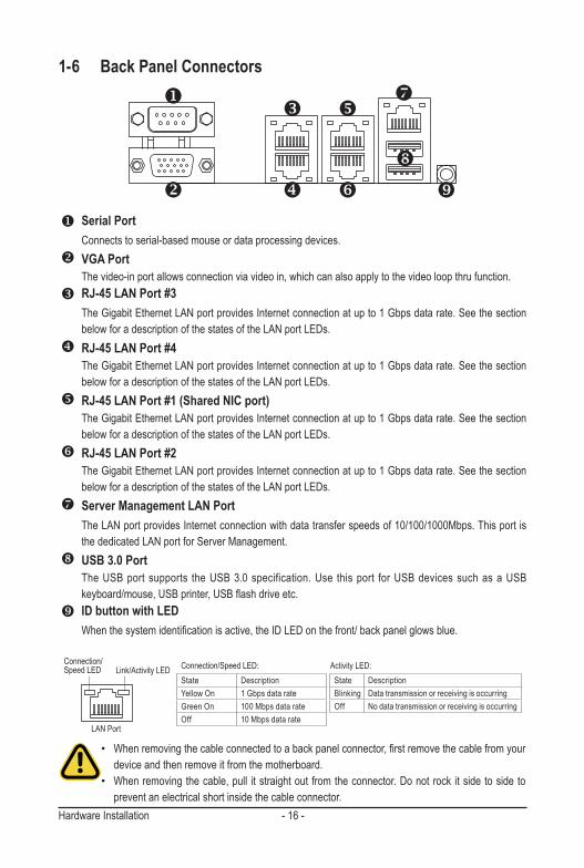
1-6 Back Panel Connectors
u Serial PortConnects to serial-based mouse or data processing devices.
v VGA PortThe video-in port allows connection via video in, which can also apply to the video loop thru function.
w RJ-45 LAN Port #3The Gigabit Ethernet LAN port provides Internet connection at up to 1 Gbps data rate. See the section below for a description of the states of the LAN port LEDs.
x RJ-45 LAN Port #4The Gigabit Ethernet LAN port provides Internet connection at up to 1 Gbps data rate. See the section below for a description of the states of the LAN port LEDs.
y RJ-45 LAN Port #1 (Shared NIC port)The Gigabit Ethernet LAN port provides Internet connection at up to 1 Gbps data rate. See the section below for a description of the states of the LAN port LEDs.
z RJ-45 LAN Port #2The Gigabit Ethernet LAN port provides Internet connection at up to 1 Gbps data rate. See the section below for a description of the states of the LAN port LEDs.
{ Server Management LAN PortThe LAN port provides Internet connection with data transfer speeds of 10/100/1000Mbps. This port is the dedicated LAN port for Server Management.
| USB 3.0 PortThe USB port supports the USB 3.0 specification. Use this port for USB devices such as a USB keyboard/mouse,USBprinter,USBflashdriveetc.
} ID button with LEDWhenthesystemidentificationisactive,theIDLEDonthefront/backpanelglowsblue.
v
w
x
y
z
{
|
}
Link/Activity LEDConnection/Speed LED
LAN Port
• Whenremovingthecableconnectedtoabackpanelconnector,firstremovethecablefromyourdevice and then remove it from the motherboard.
• When removing the cable, pull it straight out from the connector. Do not rock it side to side to prevent an electrical short inside the cable connector.
Activity LED:Connection/Speed LED:State DescriptionYellow On 1 Gbps data rateGreen On 100 Mbps data rateOff 10 Mbps data rate
State DescriptionBlinking Data transmission or receiving is occurringOff No data transmission or receiving is occurring
u
- 17 - Hardware Installation
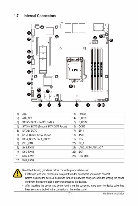
1-7 Internal Connectors
Read the following guidelines before connecting external devices:• First make sure your devices are compliant with the connectors you wish to connect.• Before installing the devices, be sure to turn off the devices and your computer. Unplug the power
cord from the power outlet to prevent damage to the devices.• After installing the device and before turning on the computer, make sure the device cable has
been securely attached to the connector on the motherboard.
DIMM_P
0_A1
DIMM_P
0_A0
DIMM_P
0_B1
DIMM_P
0_B0
CPU
213
9
1011 112
8
223
7
6
4
514
20
19
15
18
21
17
1623
1) ATX 13) PMBus2) ATX_12V 14) F_USB33) SATA0/ SATA1/ SATA2/ SATA3 15) F_USB24) SATA4/ SATA5 (Support SATA DOM Power) 16) COM25) SATA6/ SATA7 17) BP_16) SATA_DOM1/ SATA_DOM2 18) IPMB7) SATA_SGP1/ SATA_SGP2 19) TPM8) CPU_FAN 20) FP_19) SYS_FAN1 21) LAN3_ACT/ LAN4_ACT
10) SYS_FAN3 22) BAT11) SYS_FAN2 23) LED_BMC12) SYS_FAN4

Hardware Installation - 18 -
1/2) ATX/ATX_12V (2x12 Main Power Connector and 2x4 12V Power Connector)With the use of the power connector, the power supply can supply enough stable power to all the components onthemotherboard.Beforeconnectingthepowerconnector,firstmakesurethepowersupplyisturnedoffand all devices are properly installed. The power connector possesses a foolproof design. Connect the power supply cable to the power connector in the correct orientation. The 12V power connector mainly supplies power to the CPU. If the 12V power connector is not connected, the computer will not start.
To meet expansion requirements, it is recommended that a power supply that can withstand high power consumption be used (500W or greater). If a power supply is used that does not provide the required power, the result can lead to an unstable or unbootable system.
ATX
ATX_12V
12 11324
PinNo. Definition 13 3.3V 14 -12V 15 GND 16 PS_ON 17 GND 18 GND 19 GND 20 -5V 21 +5V 22 +5V 23 +5V 24 GND
PinNo. Definition 1 3.3V 2 3.3V 3 GND 4 +5V 5 GND 6 +5V 7 GND 8 Power Good 9 5VSB 10 +12V 11 +12V 12 3.3V
8
5
4
1PinNo. Definition 1 GND 2 GND 3 GND 4 GND 5 +12V 6 +12V 7 +12V 8 +12V

- 19 - Hardware Installation
3/4/5) SATA0/SATA1/SATA2/SATA3/SATA4/SATA5/SATA6/SATA7(SATA 6Gb/s Connectors)The SATA connectors conform to SATA 6Gb/s standard and are compatible with SATA 3Gb/s standard. Each SATA connector supports a single SATA device.
SATAIII_0SATAIII_1
SATAIII_2SATAIII_3
7
1
1
7
SATAIII_0
SATAIII_1
SATAIII_2
SATAIII_3
PinNo. Definition 1 GND 2 TXP 3 TXN 4 GND 5 RXN 6 RXP 7 GND
6) SATA_DOM1/ SATA_DOM2 Power ConnectorSATA-DOM (Disk on Module) is available to allow for standalone boot and diagnostics direct through SATA connections on the board.
PinNo. Definition 1 5V for SATA DOM 2 GND 3 No Connect
SATA_DOM2SATA_DOM1
SATAIII_6SATAIII_4
SATAIII_7SATAIII_5
7 1
7 1
7 1
1
SATAIII_6SATAIII_7
SATAIII_5 SATAIII_4
71
17(Support SATA DOM Power)
3 1
7

Hardware Installation - 20 -
7) SATA_SGP1/ SATA_SGP2 (SATA SGPIO) ConnectorSerial General Purpose Input/Output (SGPIO) is a communication method used between a host bus adapter (HBA) and a main board.
SATA_SGP1SATA_SGP2
PinNo. Definition 1 Data 2 GND 3 NC 4 Load 5 Clock
1 5
8/9/10/11/12) CPU_FAN/SYS_FAN1/SYS_FAN3/SYS_FAN2/SYS_FAN4 (CPU Fan/System Fan Headers)
The motherboard has one 4-pin CPU fan header (CPU_FAN), and two 4-pin (SYS_FAN) system fan headers. Most fan headers possess a foolproof insertion design. When connecting a fan cable, be sure to connect it in the correct orientation (the black connector wire is the ground wire). The motherboard supports CPU fan speed control, which requires the use of a CPU fan with fan speed control design. For optimum heat dissipation, it is recommended that a system fan be installed inside the chassis.
1
1
PinNo. Definition 1 GND 2 +12V 3 Sense 4 Speed Control
• Be sure to connect fan cables to the fan headers to prevent your CPU and system from overheating. Overheating may result in damage to the CPU or the system may hang.
• These fanheadersarenot configuration jumper blocks.Donot placea jumper capon theheaders.
CPU_FAN
SYS_FAN1
SYS_FAN3SYS_FAN2SYS_FAN4

- 21 - Hardware Installation
14/15) F_USB3/ F_USB2 (USB 3.0/ 2.0 Headers)Theheaders conform toUSB2.0/ 3.0 specification.EachUSBheader canprovide twoUSBports via anoptional USB bracket. For purchasing the optional USB bracket, please contact the local dealer.
F_USB2
PinNo. Definition 1 Power (5V) 2 Power (5V) 3 USB DX- 4 USB DY- 5 USB DX+ 6 USB DY+ 7 GND 8 GND 9 No Pin 10 No Connect
F_USB3
13) PMBus ConnectorThe Power Management Bus (PMBus) is a variant of the System Management Bus (SMBus) which is targeted at digital management of power supplies.
PMBus
5
1
USB 2.0 Header
USB 3.0 Header
1110
201
Pin No. Definition Pin No. Definition1 Power 11 IntA_P2_D+2 IntA_P1_SSRX- 12 IntA_P2_D-3 IntA_P1_SSRX+ 13 GND4 GND 14 IntA_P2_SSRX+5 IntA_P1_SSRX- 15 IntA_P2_SSRX-6 IntA_P1_SSRX+ 16 GND7 GND 17 IntA_P2_SSRX+8 IntA_P1_D- 18 IntA_P2_SSRX-9 IntA_P1_D+ 19 Power
10 NC 20 No Pin
PinNo. Definition 1 PMBus Clock 2 PMBus Data 3 PMBus Alert 4 GND 5 3.3V Sense
109
21

Hardware Installation - 22 -
16) COM2 (Serial Port Cable Connector)The COM header can provide one serial port via an optional COM port cable. For purchasing the optional COM port cable, please contact the local dealer.
COM2 PinNo. Definition 1 NDCDB_N 2 NSINB 3 NSOUTB 4 NDTRN 5 GND 6 NDSRB_N 7 NRTSB_N 8 NCTSB_N 9 NRIB_N 10 KEY
109
21
17) BP_1 (HDD Backplane Board Header)
BP_1
1 2
29 30
Pin No. Definition Pin No. Definition1 Reserved 16 BP_RST_N2 BP_SGDIN 17 SMB_U2_TMP_SCL3 GND 18 GND4 BP_SGDOUT 19 SMB_U2_TMP_SDA5 BP_SGLD 20 I2C_DEV_RST6 GND 21 Reserved7 BP_SGCLK 22 GND8 PLD_Program_EN 23 Reserved9 GLED_AMB_N 24 GND
10 GLED_GRN_N 25 Reserved11 FAN_IRQ_N 26 GND12 Reserved 27 Reserved13 BP_SCL 28 GND14 GND 29 P_3V3_AUX15 BP_SDA 30 P_3V3_AUX

- 23 - Hardware Installation
PinNo. Definition 1 Clock 2 Data 3 GND 4 VCC
18) IPMB (Intelligent Platform Management Bus) ConnectorThe Intelligent Platform Management Bus Communications Protocol defines a byte-level transport for transferringIntelligentPlatformManagementInterfaceSpecification(IPMI)messagesbetweenintelligentI2Cdevices.
IPMB
19) TPM (Trusted Platform Module Connector)Trusted Platform Module (TPM) is an international standard for a secure cryptoprocessor, a dedicated microcontroller designed to secure hardware through integrated cryptographic keys.
TPM
Pin No. Definition Pin No. Definition1 CLK_24M_TPM 8 NC2 P_3V3_AUX 9 LPC_LAD_23 RST_PLTRST 10 KEY4 P3V3 11 LPC_LAD_35 LPC_LAD_0 12 GND6 IRQ_SERIAL 13 LPC_FRAME_N7 LPC_LAD_1 14 GND
4
1
1 2
13 14

Hardware Installation - 24 -
20) FP_1 (Front Panel Header)Connect the power switch, reset switch, speaker, chassis intrusion switch/sensor and system status indicator on the chassis to this header according to the pin assignments below. Note the positive and negative pins before connecting the cables.
The front panel design may differ by chassis. A front panel module mainly consists of power switch, reset switch, power LED, hard drive activity LED, speaker etc. When connecting your chassis front panel module to this header, make sure the wire assignments and the pin assignments are matched correctly.
FP_1
Pin No. Definition Pin No. Definition1 Power LED+ 13 GND2 5V Standby 14 LAN1 Link LED-3 No Pin 15 Reset Button4 ID LED+ 16 SMBus Data5 Power LED- 17 GND6 ID LED- 18 SMBus Clock7 HDD LED+ 19 ID Button8 System Status LED(Green) 20 Case Open9 HDD LED- 21 GND
10 System Status LED(Yellow) 22 LAN2 Active LED+11 Power Button 23 NMI Switch12 LAN1 Active LED+ 24 LAN2 Link LED-
1
2423
2
21) LAN3_ACT/ LAN4_ACT (LAN3 and LAN4 Active LED Header)
LAN3_ACTLAN4_ACT
21
Pin No. Definition1 L3_ACT
2 L3_LNK-

- 25 - Hardware Installation
22) BAT (Battery Scoket)Thebatteryprovidespowertokeepthevalues(suchasBIOSconfigurations,date,andtimeinformation)inthe CMOS when the computer is turned off. Replace the battery when the battery voltage drops to a low level, or the CMOS values may not be accurate or may be lost.
• Always turn off your computer and unplug the power cord before replacing the battery.• Replace the battery with an equivalent one. Danger of explosion if the battery is replaced with an incorrect
model.• Contact the place of purchase or local dealer if you are not able to replace the battery by yourself or
uncertain about the battery model.• Used batteries must be handled in accordance with local environmental regulations.
23) LED_BMC (BMC Firmware Readiness LED)
12
State Description
On BMCfirmwareisinitial
Blink BMCfirmwareisready
Off AC loss
BAT
LED_BMC

Hardware Installation - 26 -
1-8 Jumper Settings
ME Force Update
ME_UPDATE
123
Default
Enable
ME Recovery
ME_RCVR
123
Default
Enable
Password Clear
BIOS_PWD
123
Default
Enable
Clear CMOS
CLR_CMOS
123
Default
Enable
Chassis Open Intrusion Alert
CASE_OPEN
Case openGND
BIOS Recovery
BIOS_RCVR
123
Default
Enable
Jumper Name Jumper Setting
ME Force Update 1-2: Nomal operation (Default)2-3: Enable ME Force Update
ME Recovery 1-2: Nomal operation (Default)2-3: Enable ME Recovery
Password Clear 1-2: Nomal operation (Default)2-3: Clear administrator and user passwords
Clear CMOS 1-2: Nomal operation (Default)2-3: Clear CMOS data
Chassis Open Intrusion Alert 1-2: Nomal operation (Default)
BIOS Recovery 1-2: Nomal operation (Default)2-3: Enable BIOS Recovery

- 27 - BIOS Setup
BIOS (Basic Input and Output System) records hardware parameters of the system in the EFI on the motherboard.Itsmajorfunctions includeconductingthePower-OnSelf-Test(POST)duringsystemstartup,saving system parameters, loading the operating system etc. The BIOS includes a BIOS Setup program that allowstheusertomodifybasicsystemconfigurationsettingsortoactivatecertainsystemfeatures.Whenthepower is turned off, the battery on the motherboard supplies the necessary power to the CMOS to keep the configurationvaluesintheCMOS.
To access the BIOS Setup program, press the <DEL> key during the POST when the power is turned on.
Chapter 2 BIOS Setup
• BIOSflashingispotentiallyrisky, ifyoudonotencounteranyproblemswhenusingthecurrentBIOSversion, it is recommended that youdon't flash theBIOS.To flash theBIOS, do itwithcaution.InadequateBIOSflashingmayresultinsystemmalfunction.
• It is recommended that you not alter the default settings (unless you need to) to prevent system instability or other unexpected results. Inadequately altering the settings may result in system's failure to boot. If this occurs, try to clear the CMOS values and reset the board to default values. (Refer to the Exitsectioninthischapterorintroductionsofthebattery/clearingCMOSjumperinChapter 1 for how to clear the CMOS values.)
BIOS Setup Program Function Keys <f><g> Move the selection bar to select the screen <h><i> Move the selection bar to select an item <+> Increase the numeric value or make changes <-> Decrease the numeric value or make changes <Enter> Execute command or enter the submenu <Esc> Main Menu: Exit the BIOS Setup program Submenus: Exit current submenu <F1> Show descriptions of general help <F3> Restore the previous BIOS settings for the current submenus <F9> Load the Optimized BIOS default settings for the current submenus <F10> Save all the changes and exit the BIOS Setup program

BIOS Setup - 28 -
Main This setup page includes all the items of the standard compatible BIOS. Advanced This setup page includes all the items of AMI BIOS special enhanced features. (ex:Autodetectfanandtemperaturestatus,automaticallyconfigureharddiskparameters.) Chipset ThissetuppageincludesallthesubmenuoptionsforconfiguringthefunctionsofthePlatformController
Hub. Server Management Server additional features enabled/disabled setup menus. Security Change,set,ordisablesupervisoranduserpassword.Configurationsupervisorpasswordallowsyouto
restrict access to the system and BIOS Setup. A supervisor password allows you to make changes in BIOS Setup. A user password only allows you to view the BIOS settings but not to make changes. Boot Thissetuppageprovidesitemsforconfigurationofthebootsequence. Save & Exit Save all the changes made in the BIOS Setup program to the CMOS and exit BIOS Setup. (Pressing
<F10> can also carry out this task.) Abandon all changes and the previous settings remain in effect. Pressing <Y> to the confirmation
message will exit BIOS Setup. (Pressing <Esc> can also carry out this task.)
- 29 - BIOS Setup
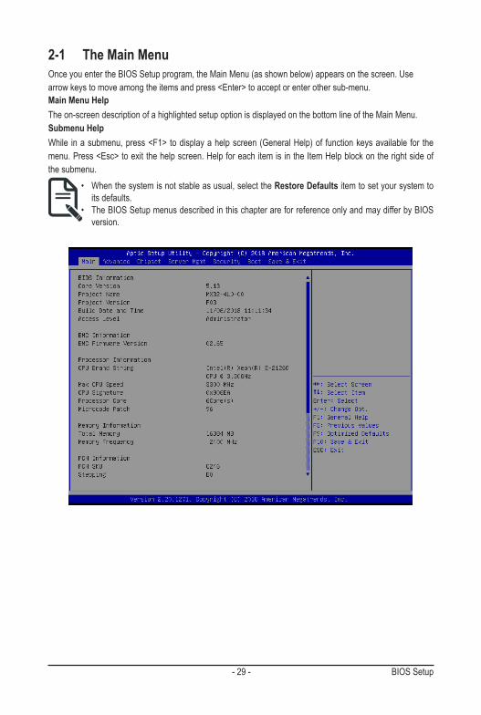
2-1 The Main MenuOnce you enter the BIOS Setup program, the Main Menu (as shown below) appears on the screen. Use arrow keys to move among the items and press <Enter> to accept or enter other sub-menu.Main Menu HelpThe on-screen description of a highlighted setup option is displayed on the bottom line of the Main Menu.Submenu HelpWhile in a submenu, press <F1> to display a help screen (General Help) of function keys available for the menu. Press <Esc> to exit the help screen. Help for each item is in the Item Help block on the right side of the submenu.
• When the system is not stable as usual, select the Restore Defaults item to set your system to its defaults.
• The BIOS Setup menus described in this chapter are for reference only and may differ by BIOS version.
BIOS Setup - 30 -
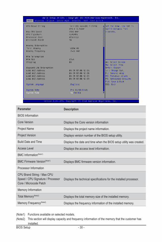
Parameter Description
BIOS Information
Core Version Displays the Core version information
ProjectName Displaystheprojectnameinformation.
ProjectVersion Displays version number of the BIOS setup utility.
Build Date and Time Displays the date and time when the BIOS setup utility was created.
Access Level Displays the access level information.
BMC Information(Note1)
BMC Firmware Version(Note1) DisplaysBMCfirmwareversioninformation.
Processor Information
CPU Brand String / Max CPU Speed / CPU Signature / Processor Core / Microcode Patch
Displaysthetechnicalspecificationsfortheinstalledprocessor.
Memory Information
Total Memory(Note2) Displays the total memory size of the installed memory.
Memory Frequency(Note2) Displays the frequency information of the installed memory.
(Note1) Functions available on selected models.(Note2) This section will display capacity and frequency information of the memory that the customer has installed.
- 31 - BIOS Setup(Note) The number of LAN ports listed will depend on the motherboard / system model.
Parameter Description
PCH Information
PCH SKU / Stepping Displays the information for the installed Platform Controller Hub.
Onboard LAN Information
LAN1 MAC Address(Note) Displays LAN MAC address information.
LAN2 MAC Address (Note) Displays LAN MAC address information.
LAN3 MAC Address(Note) Displays LAN MAC address information.
LAN4 MAC Address (Note) Displays LAN MAC address information.
System Language Displays the information of system language.
System Date Sets the date following the weekday-month-day-year format.
System Time Sets the system time following the hour-minute-second format.

BIOS Setup - 32 -
2-2 Advanced MenuTheAdvancedMenudisplayssubmenuoptionsforconfiguringthefunctionofvarioushardwarecomponents.Select a submenu item, then press <Enter> to access the related submenu screen.

- 33 - BIOS Setup
2-2-1 CPUConfiguration
Parameter Description
CPUConfiguration
Type / ID / Speed / L1 Data Cache / L1 Instruction Cache / L2 Cache/ L3 Cache
Displaysthetechnicalspecificationsfortheinstalledprocessor
Hardware Prefetcher Enable/Disable CPU Hardware Prefetcher.Options available: Enabled/Disabled. Default setting is Enabled.
AdjacentCacheLinePrefetch Enable/DisableAdjacentCacheLinePrefetch.Options available: Enabled/Disabled. Default setting is Enabled.
VT-x Enable/Disable VT-x function.Options available: Enabled/Disabled. Default setting is Enabled.
Active Processor Cores To increase or decrease the number of active processor cores.Options available: All, 1, 2, 3, 4, and 5. Defult setting is All.
Intel Trusted Execution TechonlogyEnable/Disable Intel Trusted Execution Techonlogy.Options available: Enabled/Disabled. Default setting is Disabled.

BIOS Setup - 34 -
2-2-2 PCI Subsystem Settings
(Note1) This section is dependent on the available PCIe Slot.(Note2) This section is dependent on the available LAN controller.
Parameter Description
PCI Bus Driver Version Displays the PCI Bus Driver version information.
PCI Express Slot #1 / #2 I/O ROM(Note1)When enabled, this setting will initialize the device expansion ROM for the related PCI-E slot.Options available: Enabled/Disabled. Default setting is Enabled.
Onboard LAN1 / LAN2 / LAN3 / LAN4 Controller(Note2)
Enable/Disable the onboard LAN1/ LAN2/ LAN3/ LAN4 devices.Options available: Enabled/Disabled. Default setting is Enabled.
Onboard LAN1 / LAN2 / LAN3 / LAN4 I/O ROM(Note2)
Enable/Disable the onboard LAN1/ LAN2/ LAN3/ LAN4 devices, and initializes device expansion ROM.Options available: Enabled/Disabled. Default setting is Enabled.
PCI Devices Common Settings
SR-IOV SupportIf the system has SR-IOV capable PCIe devices, this item Enable/Disable Single Root IO Virtualization Support. Options available: Enabled/Disabled. Default setting is Enabled.

- 35 - BIOS Setup
2-2-3 Power & Performance Settings
Parameter Description
Power & Performance
CPU-Power Management Control Press[Enter]toconfigureadvanceditems.

BIOS Setup - 36 -
Parameter Description
CPU-Power Management Control
Boot performance mode
Select the performance state that the BIOS will set starting from reset vector. Options available: Max Non-Turbo Performance, TurboPerformance. Default setting is Turbo Peroformance.
Intel(R) SpeedStep(tm)
Conventional Intel SpeedStep Technology switches both voltageand frequency in tandem between high and low levels inresponse to processor load.Options available: Enable/Disable. Default setting is Enabled.
Intel(R) Speed Shift Technology
Allowsthesystemtodynamicallyadjustprocessorvoltageandcore frequency, decreasing average power consumption and heat production.Options available: Enable/Disable. Default setting is Disabled.
Turbo Mode
When this item is enabled, the processor will automatically ramp up the clock speed of 1-2 of its processing cores to improve itsperformance. When this item is disabled, the processor will not overclock any of its core.Options available: Enable/Disable. Default setting is Enable.
- 37 - BIOS Setup
Parameter Description
View/ConfigureTurboOptions
Press[Enter]toconfigureadvanceditems. � EnergyEfficientP-state
– Enable/DisableEnergyEfficientP-statefeature. – Options available: Enabled/Disabled. Default setting is
Enabled.• EnergyEfficientTurbo
– Enable/DisableEnergyEfficientTurbofeature. – Options available: Enabled/Disabled. Default setting is
Enabled.
C states Enable/Disable CPU power states.Options available: Enabled/Disabled. Default setting is Enabled.
Package C State LimitConfiguresthelimitontheC-Statepackageregister.Options available: C0/C1, C2, C3, C6, C7, C7S, C8, C9, C10 and Auto. Default setting is Auto.
Interrupt Redirection Mode Selection
Select an Interrupt Redirection Mode for logcal interrupts.Options available: Fixed Priority, Round robin, Hash Vector, PAIR with Fixed Priority, PAIR with Round Robin, PAIR with Hash Vector and No Change. Default setting is PAIR with Fixed Priority.
BIOS Setup - 38 -
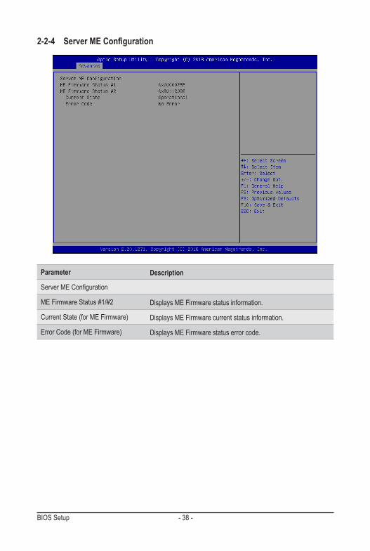
2-2-4 ServerMEConfiguration
Parameter Description
ServerMEConfiguration
ME Firmware Status #1/#2 Displays ME Firmware status information.
Current State (for ME Firmware) Displays ME Firmware current status information.
Error Code (for ME Firmware) Displays ME Firmware status error code.

- 39 - BIOS Setup
2-2-5 Trusted Computing
Parameter Description
Configuration
Security Device Support Enable/Disable the TPM support feature.Options available: Enable/Disable. Default setting is Enable.
Current Status Information Displays current TPM status information.

BIOS Setup - 40 -
2-2-6 Serial Port Console Redirection
(Note) Advanceditemspromptwhenthisitemisdefined.
Parameter Description
COM1/COM2 Serial Over LAN Console Redirection(Note)
Selectwhethertoenableconsoleredirectionforspecifieddevice.Consoleredirection enables the users to manage the system from a remote location.Options available: Enabled/Disabled. Default setting is Disabled.
Legacy Console Redirection Selects a COM port for legacy serial redirection. The options are dependent on the available COM ports.
Serial Port for Out-of-Band Management / Windows Emergency Management Services (EMS) Console Redirection(Note)
Selects a COM port for EMS console redirection. EMS console redirection allowstheusertoconfigureConsoleRedirectionSettingstosupportOut-of-Band Serial Port management.Options available: Enabled/Disabled. Default setting is Disabled.
COM1/COM2 Serial LAN/Legacy/Serial Port for Out-of-Band EMS Console Redirection Settings
Press[Enter]toconfigureadvanceditems.PleasenotethatthisitemisconfigurablewhenCOM1/COM2SerialOver LAN/Serial Port for Out-of-Band Management EMS Console Redirection is set to Enabled.
� Terminal Type – Selects a terminal type to be used for console redirection. – Options available: VT100, VT100+, ANSI , VT-UTF8. Default
setting is ANSI.
- 41 - BIOS Setup(Note) Advanceditemspromptwhenthisitemisdefined.
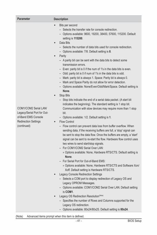
Parameter Description
COM1/COM2 Serial LAN/Legacy/Serial Port for Out-of-Band EMS Console Redirection Settings (continued)
� Bits per second – Selects the transfer rate for console redirection. – Options available: 9600, 19200, 38400, 57600, 115200. Default
setting is 115200. � Data Bits
– Selects the number of data bits used for console redirection. – Options available: 7/8. Default setting is 8.
� Parity – A parity bit can be sent with the data bits to detect some
transmission errors. – Even: parity bit is 0 if the num of 1's in the data bits is even. – Odd: parity bit is 0 if num of 1's in the data bits is odd. – Mark: parity bit is always 1. Space: Parity bit is always 0. – Mark and Space Parity do not allow for error detection. – Options available: None/Even/Odd/Mark/Space. Default setting is
None. � Stop Bits
– Stop bits indicate the end of a serial data packet. (A start bit indicates the beginning). The standard setting is 1 stop bit. Communication with slow devices may require more than 1 stop bit.
– Options available: 1/2. Default setting is 1. � Flow Control
– Flowcontrolcanpreventdatalossfrombufferoverflow.Whensending data, if the receiving buffers are full, a 'stop' signal can besenttostopthedataflow.Oncethebuffersareempty,a'start'signalcanbesenttore-starttheflow.Hardwareflowcontrolusestwo wires to send start/stop signals.
– For COM1/COM2 Serial Over LAN: » Options available: None, Hardware RTS/CTS. Default setting is None.
– For Serial Port for Out-of-Band EMS: » Options available: None, Hardware RTS/CTS and Software Xon/Xoff. Default setting is Hardware RTS/CTS.
� Legacy Console Redirection Settings – Selects a COM port to display redirection of Legacy OS and
Legacy OPROM Messages. – Options available: COM1/COM2 Serial Over LAN. Default setting
is COM1. � Legacy OS Redirection Resolution(Note)
– SpecifiesthenumberofRowsandColumnssupportedfortheLegacy OS redirection.
– Options available: 80x24/80x25. Default setting is 80x24.
BIOS Setup - 42 -(Note) Advanceditemspromptwhenthisitemisdefined.
Parameter Description
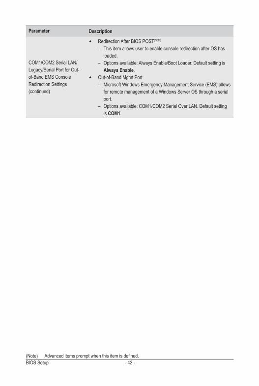
COM1/COM2 Serial LAN/Legacy/Serial Port for Out-of-Band EMS Console Redirection Settings (continued)
� Redirection After BIOS POST(Note)
– This item allows user to enable console redirection after OS has loaded.
– Options available: Always Enable/Boot Loader. Default setting is Always Enable.
� Out-of-Band Mgmt Port – Microsoft Windows Emergency Management Service (EMS) allows
for remote management of a Windows Server OS through a serial port.
– Options available: COM1/COM2 Serial Over LAN. Default setting is COM1.

- 43 - BIOS Setup
2-2-7 AST2500SuperIOConfiguration
Parameter Description
AST2500SuperIOConfiguration
Super IO Chip Displays the Super IO Chip information.
SerialPort1/2Configuration Press[Enter]toconfigureadvanceditems.
BIOS Setup - 44 -
Parameter Description
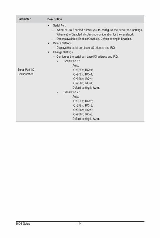
Serial Port 1/2 Configuration
� Serial Port – When set to Enabled allows you to configure the serial port settings. WhensettoDisabled,displaysnoconfigurationfortheserialport.
– Options available: Enabled/Disabled. Default setting is Enabled. � Device Settings
– Displays the serial port base I/O address and IRQ. � Change Settings:
– ConfigurestheserialportbaseI/OaddressandIRQ. » Serial Port 1 :
Auto; IO=3F8h; IRQ=4; IO=2F8h; IRQ=4;IO=3E8h; IRQ=4;IO=2E8h; IRQ=4;Default setting is Auto.
» Serial Port 2 :Auto; IO=3F8h; IRQ=3; IO=2F8h; IRQ=3;IO=3E8h; IRQ=3;IO=2E8h; IRQ=3;Default setting is Auto.

- 45 - BIOS Setup
2-2-8 NetworkStackConfiguration
(Note) This item appears when Network Stack is set to Enabled.
Parameter Description
Network Stack Enable/Disable the UEFI network stack.Options available: Enabled/Disabled. Default setting is Enabled.
Ipv4 PXE Support(Note) Enable/Disable the Ipv4 PXE feature.Options available: Enabled/Disabled. Default setting is Enabled.
Ipv4 HTTP Support(Note) Enable/Disable the Ipv4 HTTP feature.Options available: Enabled/Disabled. Default setting is Disabled.
Ipv6 PXE Support(Note) Enable/Disable the Ipv6 PXE feature.Options available: Enabled/Disabled. Default setting is Disabled.
Ipv6 HTTP Support(Note) Enable/Disable the Ipv6 HTTP feature.Options available: Enabled/Disabled. Default setting is Disabled.
PXE boot wait time(Note) Press the <+> / <-> keys to increase or decrease the desired values.
Media detect count(Note) Press the <+> / <-> keys to increase or decrease the desired values.
BIOS Setup - 46 -
2-2-9 USBConfiguration
(Note) This item is present only if you attach USB devices.
Parameter Description
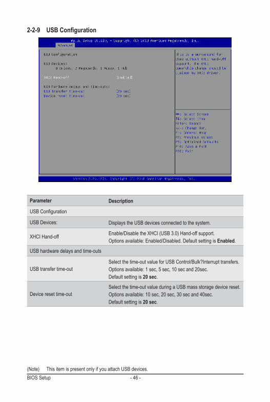
USBConfiguration
USB Devices: Displays the USB devices connected to the system.
XHCI Hand-off Enable/Disable the XHCI (USB 3.0) Hand-off support. Options available: Enabled/Disabled. Default setting is Enabled.
USB hardware delays and time-outs
USB transfer time-outSelect the time-out value for USB Control/Bulk?Interrupt transfers.Options available: 1 sec, 5 sec, 10 sec and 20sec.Default setting is 20 sec.
Device reset time-outSelect the time-out value during a USB mass storage device reset. Options available: 10 sec, 20 sec, 30 sec and 40sec. Default setting is 20 sec.

- 47 - BIOS Setup
2-2-10 Runtime Error Logging Settings
Parameter Description
Runtime Error Logging Settings
Runtime Error Logging SystemEnabling
Enable/Disable runtime logging error system function.Options available: Enable/Disabled. Default setting is Enable.
Memory Error Enabling Enable/Disable the Memory Error log functionOptions available: Enable/Disabled. Default setting is Enable.
PCI/PCI Error Enabling Enable/Disable the PCI/PCI log functionOptions available: Enable/Disabled. Default setting is Disabled.

BIOS Setup - 48 -
2-2-11 S5 RTC Wake Settings
Parameter Description
Wake System from S5
Enable/Disable system wake on alarm event.Options available: Disabled/Fixed Time. When Fixed Time enabled, system willwakeonthehr::min::secspecified.Default setting is Enable.

- 49 - BIOS Setup
2-2-12 NVMeConfiguration
Parameter Description
NVMeConfiguration Displays the NVMe devices connected to the system

BIOS Setup - 50 -
2-2-13 OffBoardSATAControllerConfiguration
Parameter Description
Offboard SATA Controller Configuration Displays the information on your PCIe SATA controllers/ PCIe SSD if installed

- 51 - BIOS Setup
2-2-14 ChipsetConfiguration
(Note) When the power policy is controlled by BMC, please wait for 15-20 seconds for BMC to save the last power state.
Parameter Description
Restore on AC Power Loss(Note)
Definesthepowerstatetoresumetoafterasystemshutdownthatisdue to an interruption in AC power. When set to Last State, the system will return to the active power state prior to shutdown. When set to Power Off, the system remains off after power shutdown.Options available: Last State, Power Off, Power On. The default setting depends on the BMC setting.
Chassis Opened WarningEnable/Disable the chassis intrusion alert function.Options available: Enabled, Disabled, Clear. Default setting is Disabled.

BIOS Setup - 52 -
2-2-15 iSCSIConfiguration
Parameter Description
iSCSI Initiator Name
Add an Attempt Press[Enter]toconfigureadvanceditems.
Delete Attempts Press[Enter]toconfigureadvanceditems.
Change Attempt Order Press[Enter]toconfigureadvanceditems.
- 53 - BIOS Setup
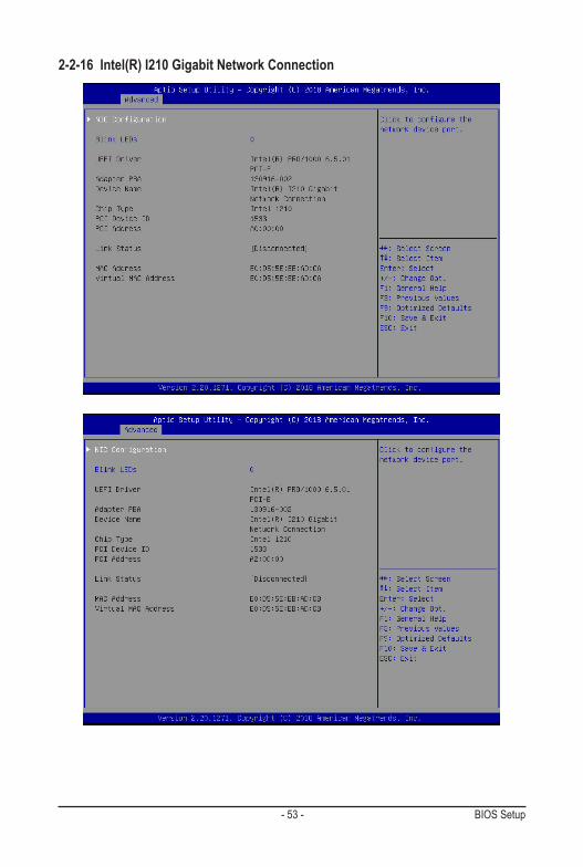
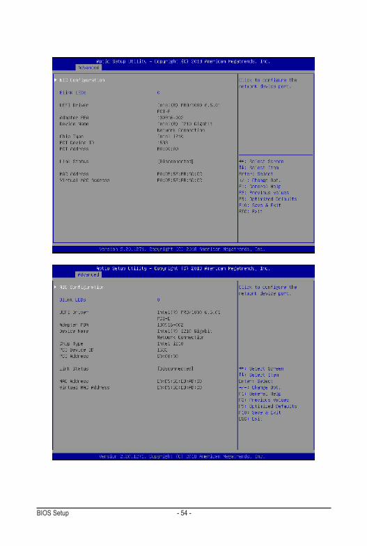
2-2-16 Intel(R) I210 Gigabit Network Connection
BIOS Setup - 54 -
- 55 - BIOS Setup
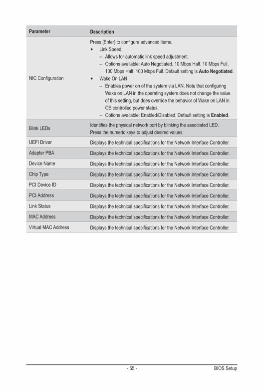
Parameter Description
NICConfiguration
Press[Enter]toconfigureadvanceditems. � Link Speed
– Allowsforautomaticlinkspeedadjustment. – Options available: Auto Negotiated, 10 Mbps Half, 10 Mbps Full,
100 Mbps Half, 100 Mbps Full. Default setting is Auto Negotiated. � Wake On LAN
– EnablespoweronofthesystemviaLAN.NotethatconfiguringWake on LAN in the operating system does not change the value of this setting, but does override the behavior of Wake on LAN in OS controlled power states.
– Options available: Enabled/Disabled. Default setting is Enabled.
Blink LEDs IdentifiesthephysicalnetworkportbyblinkingtheassociatedLED.Pressthenumerickeystoadjustdesiredvalues.
UEFI Driver DisplaysthetechnicalspecificationsfortheNetworkInterfaceController.
Adapter PBA DisplaysthetechnicalspecificationsfortheNetworkInterfaceController.
Device Name DisplaysthetechnicalspecificationsfortheNetworkInterfaceController.
Chip Type DisplaysthetechnicalspecificationsfortheNetworkInterfaceController.
PCI Device ID DisplaysthetechnicalspecificationsfortheNetworkInterfaceController.
PCI Address DisplaysthetechnicalspecificationsfortheNetworkInterfaceController.
Link Status DisplaysthetechnicalspecificationsfortheNetworkInterfaceController.
MAC Address DisplaysthetechnicalspecificationsfortheNetworkInterfaceController.
Virtual MAC Address DisplaysthetechnicalspecificationsfortheNetworkInterfaceController.

BIOS Setup - 56 -
2-2-17 VLANConfiguration

- 57 - BIOS Setup
Parameter Description
EnterConfigurationMenu
Press[Enter]toconfigureadvanceditems. � Create new VLAN � VLAN ID
– Sets VLAN ID for a new VLAN or an existing VLAN. – Press the <+> / <-> keys to increase or decrease the desired values. – The valid range is from 0 to 4094.
� Priority – Sets 802.1Q Priority for a new VLAN or an existing VLAN. – Press the <+> / <-> keys to increase or decrease the desired values. – The valid range is from 0 to 7.
� Add VLAN – Press [Enter] to create a new VLAN or update an existing VLAN.
� ConfiguredVLANList � Remove VLAN
– Press [Enter] to remove an existing VLAN.

BIOS Setup - 58 -
2-2-18 Driver Health
Parameter Description
Driver Health Displays driver health status of the devices/controllers if installed
- 59 - BIOS Setup
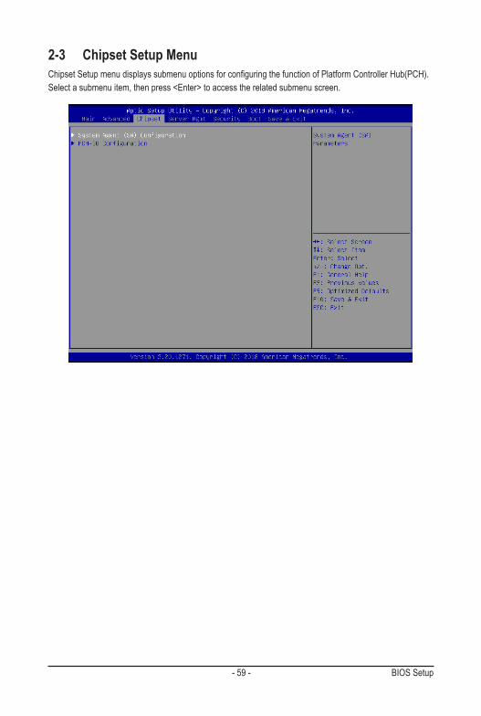
2-3 Chipset Setup MenuChipsetSetupmenudisplayssubmenuoptionsforconfiguringthefunctionofPlatformControllerHub(PCH).Select a submenu item, then press <Enter> to access the related submenu screen.
BIOS Setup - 60 -
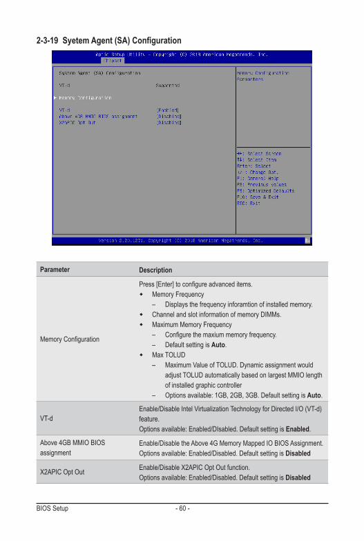
2-3-19 SyetemAgent(SA)Configuration
Parameter Description
MemoryConfiguration
Press[Enter]toconfigureadvanceditems. � Memory Frequency
– Displays the frequency inforamtion of installed memory. � Channel and slot information of memory DIMMs. � Maximum Memory Frequency
– Configurethemaxiummemoryfrequency. – Default setting is Auto.
� Max TOLUD – Maximum Value of TOLUD. Dynamic assignment would
adjustTOLUDautomaticallybasedonlargestMMIOlengthof installed graphic controller
– Options available: 1GB, 2GB, 3GB. Default setting is Auto.
VT-dEnable/Disable Intel Virtualization Technology for Directed I/O (VT-d) feature.Options available: Enabled/DIsabled. Default setting is Enabled.
Above 4GB MMIO BIOS assignment
Enable/Disable the Above 4G Memory Mapped IO BIOS Assignment.Options available: Enabled/Disabled. Default setting is Disabled
X2APIC Opt Out Enable/Disable X2APIC Opt Out function.Options available: Enabled/Disabled. Default setting is Disabled
- 61 - BIOS Setup
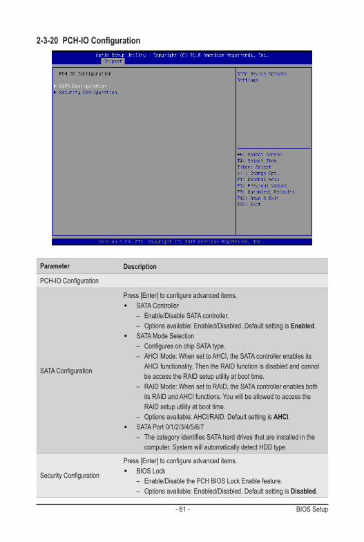
2-3-20 PCH-IOConfiguration
Parameter Description
PCH-IOConfiguration
SATAConfiguration
Press[Enter]toconfigureadvanceditems. � SATA Controller
– Enable/Disable SATA controller. – Options available: Enabled/Disabled. Default setting is Enabled.
� SATA Mode Selection – ConfiguresonchipSATAtype. – AHCI Mode: When set to AHCI, the SATA controller enables its
AHCI functionality. Then the RAID function is disabled and cannot be access the RAID setup utility at boot time.
– RAID Mode: When set to RAID, the SATA controller enables both its RAID and AHCI functions. You will be allowed to access the RAID setup utility at boot time.
– Options available: AHCI/RAID. Default setting is AHCI. � SATA Port 0/1/2/3/4/5/6/7
– ThecategoryidentifiesSATAharddrivesthatareinstalledinthecomputer. System will automatically detect HDD type.
SecurityConfiguration
Press[Enter]toconfigureadvanceditems. � BIOS Lock
– Enable/Disable the PCH BIOS Lock Enable feature. – Options available: Enabled/Disabled. Default setting is Disabled.

BIOS Setup - 62 -
2-4 Server Management Menu
Parameter Description
FRB-2 Timer Enable/Disable FRB-2 timer (POST timer).Options available: Enabled/Disabled. Default setting is Disabled.
FRB-2 Timer timeout
ConfiguretheFRB2Timertimeout.Options available: 3 minutes, 4 minutes, 5 minutes, 6 minutes. Default setting is 6 minutes.PleasenotethatthisitemisconfigurablewhenFRB-2TimerissettoEnabled.
FRB-2 Timer PolicyConfiguretheFRB2Timerpolicy.Options available: Do Nothing, Reset, Power Down. Default setting is Do Nothing.PleasenotethatthisitemisconfigurablewhenFRB-2TimerissettoEnabled.
OS Watchdog Timer
Enable/Disable OS Watchdog Timer function.Options available: Enabled/Disabled. Default setting is Disabled.
OS Wtd Timer Timeout
ConfigureOSWatchdogTimer.Options available: 5 minutes, 10 minutes, 15 minutes, 20 minutes. Default setting is 5 minutes.PleasenotethatthisitemisconfigurablewhenOSWatchdogTimerissettoEnabled.
OS Wtd Timer Policy
ConfigureOSWatchdogTimerPolicy.Options available: Reset, Do Nothing, Power Down. Default setting is Reset.PleasenotethatthisitemisconfigurablewhenOSWatchdogTimerissettoEnabled.

- 63 - BIOS Setup
Parameter Description
System Event Log Press[Enter]toconfigureadvanceditems.
View FRU Information Press [Enter] to view the advanced items.
BMC network configuration Press[Enter]toconfigureadvanceditems.
IPv6 BMC Network Configuration Press[Enter]toconfigureadvanceditems.
BIOS Setup - 64 -
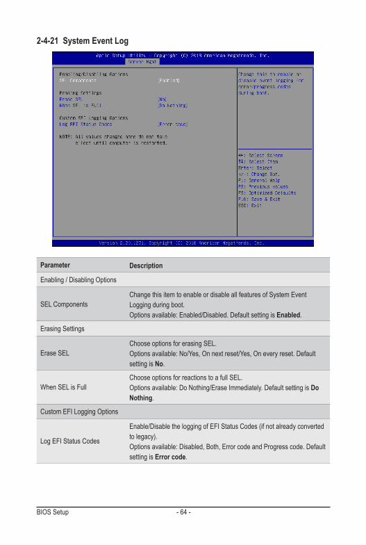
2-4-21 System Event Log
Parameter Description
Enabling / Disabling Options
SEL ComponentsChange this item to enable or disable all features of System Event Logging during boot.Options available: Enabled/Disabled. Default setting is Enabled.
Erasing Settings
Erase SELChoose options for erasing SEL.Options available: No/Yes, On next reset/Yes, On every reset. Default setting is No.
When SEL is FullChoose options for reactions to a full SEL.Options available: Do Nothing/Erase Immediately. Default setting is Do Nothing.
Custom EFI Logging Options
Log EFI Status Codes
Enable/Disable the logging of EFI Status Codes (if not already converted to legacy).Options available: Disabled, Both, Error code and Progress code. Default setting is Error code.

- 65 - BIOS Setup
2-4-22 View FRU InformationThe FRU page is a simple display page for basic system ID information, as well as System product information.Itemsonthiswindowarenon-configurable.
(Note) The model name will vary depends on the product you purchased

BIOS Setup - 66 -
2-4-23 BMCNetworkConfiguration
Parameter Description
BMCnetworkconfiguration
Lan Channel 1
ConfigurationAddresssource
SelecttoconfigureLANchannelparametersstaticallyordynamically(DHCP). Do nothing option will not modify any BMC network parameters during BIOS phase.Optionsavailable:Unspecified,StaticandDynamicBmcDhcp.Defaultsetting is DynamicBmcDhcp.
Station IP address Displays IP Address information.
Subnet maskDisplays Subnet Mask information.Please note that the IP address must be in three digitals, for example, 192.168.000.001.
Router IP address Displays the Router IP Address information.
Station MAC address Displays the MAC Address information.
Real-time synchronize BMC network parameter values Press [Enter] to synchronize the BMC network parameter values.

- 67 - BIOS Setup
2-4-24 IPv6BMCNetworkConfiguration
Parameter Description
IPv6 BMC Network Configuration
IPv6 BMC Lan Channel 1
IPv6 BMC Lan Option
Enable/Disable IPv6 BMC LAN channel function. When this item is disabled, the system will not modify any BMC network during BIOS phase.Optionsavailable:Unspecified,EnableandDisable.DefaultsettingisEnable.
IPv6 BMC Lan IP Address Source
SelecttoconfigureLANchannelparametersstaticallyordynamically(byBIOS or BMC).Options available: Unspecified, Static and Dynamic-Obtained by BMC running DHCP.Default setting is Dynamic-Obtained by BMC running DHCP.
IPv6 BMC Lan IP Address/PrefixLength
Check if the IPv6 BMC LAN IP address matches those displayed on the screen.

BIOS Setup - 68 -
2-5 Security MenuThe Security menu allows you to safeguard and protect the system from unauthorized use by setting up access passwords.
There are two types of passwords that you can set:• Administrator Password Entering this password will allow the user to access and change all settings in the Setup Utility. • User Password Entering this password will restrict a user’s access to the Setup menus. To enable or disable thisfield,aAdministratorPasswordmustfirstbeset.Ausercanonlyaccessandmodifythe SystemTime,SystemDate,andSetUserPasswordfields.
Parameter Description
Administrator Password Press[Enter]toconfiguretheadministratorpassword.
User Password Press[Enter]toconfiguretheuserpassword.
RuntimeVariable Protection Support
Enable/Disable Runtime Variable protection support.Options available: Enable/Disable. Default setting is Disabled.
Secure Boot Press[Enter]toconfigureadvanceditems.

- 69 - BIOS Setup
2-5-25 Secure Boot The Secure Boot submenu is applicable when your device is installed the Windows® 8 (or above) operating system.
(Note) Advanced items prompt when this item is set to Custom.
Parameter Description
System Mode Displays if the system is in User mode or Setup mode.
Secure Boot Enable/ Disable the Secure Boot function.Options avaiable:Enabled/Disabled. Default setting is Disabled.
Secure Boot Mode(Note)
Secure Boot requires all the applications that are running during the bootingprocesstobepre-signedwithvaliddigitalcertificates.Thisway,thesystemknowsallfilesbeingloadedbeforeWindowsloadstotheloginscreen have not been tampered with.When set to Standard, it will automatically load the Secure Boot keys form the BIOS databases.When set to Custom, you can customize the Secure Boot settings and manually load its keys from the BIOS database.Options available: Standard/Custom. Default setting is Standard.
BIOS Setup - 70 -
Parameter Description
Key Management
Press[Enter]toconfigureadvanceditems.PleasenotethatthisitemisconfigurablewhenSecureBootModeissetto Custom.
� Factory Key Provision – Allows to provision factory default Secure Boot keys when system is in
Setup Mode. – Options available: Enabled/Disabled. Default setting is Disabled.
� Restore Factory Keys – Installs all factory default keys. It will force the system in User Mode. – Options available: Yes/No.
� EnrollEfiImage – Press [Enter] to enroll SHA256 hash of the binary into Authorized
Signature Database (db). � Restore DB defaults
– Restore DB variable to factory defaults. � Secure Boot variable
– Displays the current status of the variables used for secure boot. � Platform Key (PK)
– Displays the current status of the Platform Key (PK). – Press[Enter]toconfigureanewPK. – Options available: Set New.
� Key Exchange Keys (KEK) – Displays the current status of the Key Exchange Key Database (KEK). – Press[Enter]toconfigureanewKEKorloadadditionalKEKfrom
storage devices. – Options available: Set New/Append.
� Authorized Signatures (DB) – Displays the current status of the Authorized Signature Database. – Press[Enter]toconfigureanewDBorloadadditionalDBfromstorage
devices. – Options available: Set New/Append.
� Forbidden Signatures (DBX) – Displays the current status of the Forbidden Signature Database. – Press[Enter]toconfigureanewdbxorloadadditionaldbxfrom
storage devices. – Options available: Set New/Append.
� Authorized TimeStamps (DBT) – Displays the current status of the Authorized TimeStamps Database. – Press[Enter]toconfigureanewDBTorloadadditionalDBTfrom
storage devices. – Options available: Set New/Append.
� OsRecovery Signatures – Displays the current status of the OsRecovery Signature Database. – Press[Enter]toconfigureanewOsRecoverySignatureorload
additional OsRecovery Signature from storage devices. – Options available: Set New/Append.
- 71 - BIOS Setup
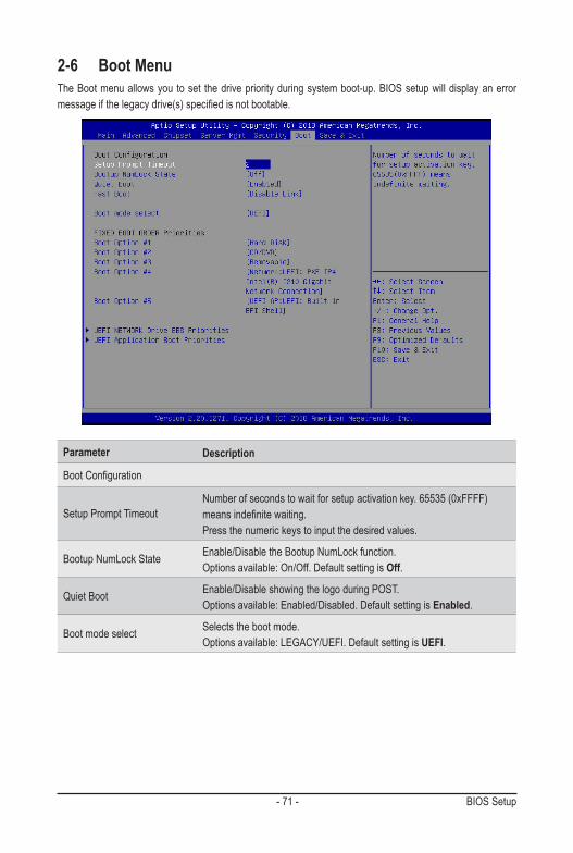
2-6 Boot MenuThe Boot menu allows you to set the drive priority during system boot-up. BIOS setup will display an error messageifthelegacydrive(s)specifiedisnotbootable.
Parameter Description
BootConfiguration
Setup Prompt TimeoutNumber of seconds to wait for setup activation key. 65535 (0xFFFF) meansindefinitewaiting.Press the numeric keys to input the desired values.
Bootup NumLock State Enable/Disable the Bootup NumLock function.Options available: On/Off. Default setting is Off.
Quiet Boot Enable/Disable showing the logo during POST.Options available: Enabled/Disabled. Default setting is Enabled.
Boot mode select Selects the boot mode.Options available: LEGACY/UEFI. Default setting is UEFI.
BIOS Setup - 72 -
Parameter Description
FIXED BOOT ORDER Priorities
Boot Option #1 / #2 / #3 / #4 / #5
Press[Enter]toconfigurethebootpriority.By default, the server searches for boot devices in the following sequence:
1. Hard drive.2. CD-COM/DVD drive.3. USB device.4. Network.5. UEFI.
UEFI Network Drive BBS Priorities Press[Enter]toconfigurethebootpriority.
UEFI Application Boot Priorities Press[Enter]toconfigurethebootpriority.

- 73 - BIOS Setup
2-6-26 UEFI NETWORK Drive BBS Priorities The UEFI network drive BBS priorities submenu allows you to specify the boot device priority from the available UEFI network drives during system boot-up. BIOS setup will display an error message if the legacy drive(s)specifiedisnotbootable.

BIOS Setup - 74 -
2-6-27 UEFI Application Boot Priorities The UEFI application boot priorities submenu allows you to specify the boot device priority from the available UEFI applications during system boot-up. BIOS setup will display an error message if the legacy drive(s) specifiedisnotbootable.

- 75 - BIOS Setup
2-7 Save & Exit MenuThe Save & Exit menu displays the various options to quit from the BIOS setup. Highlight any of the exit options then press <Enter>.
Parameter Description
Save Options
Save Changes and Exit Saves changes made and closes the BIOS setup. Options available: Yes/No.
Discard Changes and Exit Discards changes made and exits the BIOS setup.Options available: Yes/No.
Save Changes and Reset Restarts the system after saving the changes made. Options available: Yes/No.
Discard Changes and Reset Restarts the system without saving any changes.Options available: Yes/No.
Save Changes Saves changes made in the BIOS setup.Options available: Yes/No.
Discard Changes Discards changes made and closes the BIOS setup.Options available: Yes/No.

BIOS Setup - 76 -
Parameter Description
Default Options
Restore Defaults
Loads the default settings for all BIOS setup parameters. Setup Defaults are quite demanding in terms of resources consumption. If you are using low-speed memory chips or other kinds of low-performance components and you choose to load these settings, the system might not function properly.Options available: Yes/No.
Save as User Defaults Saves the changes made as the user default settings.Options available: Yes/No.
Restore User Defaults Loads the user default settings for all BIOS setup parameters.Options available: Yes/No.
Boot Override Press[Enter]toconfigurethedeviceastheboot-updrive.

- 77 - BIOS Setup
2-8 BIOS POST Codes2-8-28 AMI Standard - PEI
PEI_CORE_STARTED 0x10PEI_CAR_CPU_INIT 0x11PEI_CAR_NB_INIT 0x15PEI_CAR_SB_INIT 0x19PEI_MEMORY_SPD_READ 0x2BPEI_MEMORY_PRESENCE_DETECT 0x2CPEI_MEMORY_TIMING 0x2DPEI_MEMORY_CONFIGURING 0x2EPEI_MEMORY_INIT 0x2FPEI_MEMORY_INSTALLED 0x31PEI_CPU_INIT 0x32PEI_CPU_CACHE_INIT 0x33PEI_CPU_AP_INIT 0x34PEI_CPU_BSP_SELECT 0x35PEI_CPU_SMM_INIT 0x36PEI_MEM_NB_INIT 0x37PEI_MEM_SB_INIT 0x3BPEI_DXE_IPL_STARTED 0x4FDXE_CORE_STARTED 0x60//RecoveryPEI_RECOVERY_AUTO 0xF0PEI_RECOVERY_USER 0xF1PEI_RECOVERY_STARTED 0xF2PEI_RECOVERY_CAPSULE_FOUND 0xF3PEI_RECOVERY_CAPSULE_LOADED 0xF4//S3PEI_S3_STARTED 0xE0PEI_S3_BOOT_SCRIPT 0xE1PEI_S3_VIDEO_REPOST 0xE2PEI_S3_OS_WAKE 0xE3
2-8-29 AMI Standard - DXEDXE_CORE_STARTED 0x60DXE_NVRAM_INIT 0x61DXE_SBRUN_INIT 0x62DXE_CPU_INIT 0x63DXE_NB_HB_INIT 0x68DXE_NB_INIT 0x69DXE_NB_SMM_INIT 0x6A

BIOS Setup - 78 -
DXE_SB_INIT 0x70DXE_SB_SMM_INIT 0x71DXE_SB_DEVICES_INIT 0x72DXE_ACPI_INIT 0x78DXE_CSM_INIT 0x79DXE_BDS_STARTED 0x90DXE_BDS_CONNECT_DRIVERS 0x91DXE_PCI_BUS_BEGIN 0x92DXE_PCI_BUS_HPC_INIT 0x93DXE_PCI_BUS_ENUM 0x94DXE_PCI_BUS_REQUEST_RESOURCES 0x95DXE_PCI_BUS_ASSIGN_RESOURCES 0x96DXE_CON_OUT_CONNECT 0x97DXE_CON_IN_CONNECT 0x98DXE_SIO_INIT 0x99DXE_USB_BEGIN 0x9ADXE_USB_RESET 0x9BDXE_USB_DETECT 0x9CDXE_USB_ENABLE 0x9DDXE_IDE_BEGIN 0xA0DXE_IDE_RESET 0xA1DXE_IDE_DETECT 0xA2DXE_IDE_ENABLE 0xA3DXE_SCSI_BEGIN 0xA4DXE_SCSI_RESET 0xA5DXE_SCSI_DETECT 0xA6DXE_SCSI_ENABLE 0xA7DXE_SETUP_VERIFYING_PASSWORD 0xA8DXE_SETUP_START 0xA9DXE_SETUP_INPUT_WAIT 0xABDXE_READY_TO_BOOT 0xADDXE_LEGACY_BOOT 0xAEDXE_EXIT_BOOT_SERVICES 0xAFRT_SET_VIRTUAL_ADDRESS_MAP_BEGIN 0xB0RT_SET_VIRTUAL_ADDRESS_MAP_END 0xB1DXE_LEGACY_OPROM_INIT 0xB2DXE_RESET_SYSTEM 0xB3DXE_USB_HOTPLUG 0xB4DXE_PCI_BUS_HOTPLUG 0xB5DXE_NVRAM_CLEANUP 0xB6DXE_CONFIGURATION_RESET 0xB7

- 79 - BIOS Setup
2-8-30 AMI Standard - ERRORPEI_MEMORY_INVALID_TYPE 0x50PEI_MEMORY_INVALID_SPEED 0x50PEI_MEMORY_SPD_FAIL 0x51PEI_MEMORY_INVALID_SIZE 0x52PEI_MEMORY_MISMATCH 0x52PEI_MEMORY_NOT_DETECTED 0x53PEI_MEMORY_NONE_USEFUL 0x53PEI_MEMORY_ERROR 0x54PEI_MEMORY_NOT_INSTALLED 0x55PEI_CPU_INVALID_TYPE 0x56PEI_CPU_INVALID_SPEED 0x56PEI_CPU_MISMATCH 0x57PEI_CPU_SELF_TEST_FAILED 0x58PEI_CPU_CACHE_ERROR 0x58PEI_CPU_MICROCODE_UPDATE_FAILED 0x59PEI_CPU_NO_MICROCODE 0x59PEI_CPU_INTERNAL_ERROR 0x5APEI_CPU_ERROR 0x5APEI_RESET_NOT_AVAILABLE 0x5B //RecoveryPEI_RECOVERY_PPI_NOT_FOUND 0xF8PEI_RECOVERY_NO_CAPSULE 0xF9PEI_RECOVERY_INVALID_CAPSULE 0xFA//S3 ResumePEI_MEMORY_S3_RESUME_FAILED 0xE8PEI_S3_RESUME_PPI_NOT_FOUND 0xE9PEI_S3_BOOT_SCRIPT_ERROR 0xEAPEI_S3_OS_WAKE_ERROR 0xEBDXE_CPU_ERROR 0xD0DXE_NB_ERROR 0xD1DXE_SB_ERROR 0xD2DXE_ARCH_PROTOCOL_NOT_AVAILABLE 0xD3DXE_PCI_BUS_OUT_OF_RESOURCES 0xD4DXE_LEGACY_OPROM_NO_SPACE 0xD5DXE_NO_CON_OUT 0xD6DXE_NO_CON_IN 0xD7DXE_INVALID_PASSWORD 0xD8DXE_BOOT_OPTION_LOAD_ERROR 0xD9DXE_BOOT_OPTION_FAILED 0xDADXE_FLASH_UPDATE_FAILED 0xDBDXE_RESET_NOT_AVAILABLE 0xDC

BIOS Setup - 80 -
2-8-31 Intel UPI POST Codes
2-8-32 Intel UPI Error Codes
Initialize KTIRC inuput structure default values 0xA0Collect info such as SBSP, Boot Mode, Reset type etc 0xA1SetupIOSADsinSBSPtoaccesstheconfigspace 0xA2Setup up minimum path between SBSP & other socketsAdd the node to the treeParse the LEP of the discovered socketCheck if the system has the supported topologySetup the boot path for the parent which is not directly connected to Legacy CPUSetup path from SBSP to the new found node
0xA3
SetupIOSADsinPBSPtoaccesstheconfigspace 0xA4Systemconfigurationsthatrequiresomekindofreset 0xA5Sync up with PBSPs 0xA6Topology discovery and route calculation 0xA7Programfinalroute 0xA8ProgramfinalIOSADsetting 0xA9Protocol layer and other Uncore settings 0xAATransition links to full speed operation 0xABPhy layer settings 0xACLink layer settings 0xADCoherency Settings 0xAEKTIRC is done 0xAF
When system BSP tries to setup path for remote sockets or sends a Boot_Go command to remote socket in SetupSbspPathToAllSockets() or SyncUpPbspForReset(). If the remote socket(s) hasn't checked-in, assert; it is a fatal condition, this error will be logged. No retry.RC Behavior: System Halt
0xD8
When SBSP tries to add this remote socket into system topology tree in SetupSbspPathToAllSockets(), there are some errors occur in the data structure. No retry.RC Behavior: The current Socket is not added to the tree.When SBSP setups the boot path for the parent which is not directly connected to Legacy CPU in SetupSbspPathToAllSockets(). The Child is not an immediate neighbor of Parent. No retry.
0xDA

- 81 - BIOS Setup
2-8-33 Intel MRC POST Codes
2-8-34 Intel MRC Error Codes
SAD setup errorRC Behavior: System Halt
0xDB
Unsupported topologyRC Behavior: System Halt
0xDC
SBSPcannotfindKPIRCTXEQParametersforthislink in GetSocketLinkEparams(). No retry.RC Behavior: System Halt
0xDD
Detect DIMM population 0xB0Set DDR frequency 0xB1Gather remaining SPD data 0xB2Program registers on the memory controller level 0xB3Evaluate RAS modes and save rank information 0xB4Program registers on the channel level 0xB5DDRIO Initialization 0xB6Train DDR 0xB7Initialize CLTT/OLTT 0xB8Hardware memory test and init 0xB9Execute memory init 0xBAProgram memory map and interleaving 0xBBProgramRASconfiguration 0xBCRank margin tool 0xBDMRC is done 0xBF
No memory was detected 0xE8Memory test failure 0xEBDifferent dimm types are detected installed in the system 0xEDNumber of HAs found in system greater than MAX_HAdefinedinMRCbuild
0xEE
Indicates a CLTT table structure error 0xEFInvalid VR mode, unable to set DRAM VDD 0xF0Failure occurred reserving memory for IOT 0xF1Reference code assert 0xF2Unsupported MC frequency set 0xF3Unable to get current MC frequency 0xF4

BIOS Setup - 82 -
2-8-35 Intel PM POST Codes
2-8-36 Intel PM POST Codes
Start of PPM structure initialization 0xD0PPM CSR programming 0xD1PPM MSR programming 0xD2Start of PState transition init 0xD3PPM exit 0xD4PPM On ready to boot event 0xD5
Start of IIO early Initialization 0xE0Pre Link training 0xE1Start of Gen3 EQ training 0xE2Start of PState transition init 0xE3Gen3 parameters override 0xE4End of IIO Early Initialization 0xE5Start of IIO Late initialization 0xE6PCIE port initialization 0xE7IOAPIC initialization 0xE8VTD initialization 0xE9IOAT initialization 0xEADFX initialization 0xEBNTB initialization 0xECSecurity Initialization 0xEDIIO late initialization 0xEEIIO On ready to boot event 0xEF

- 83 - BIOS Setup
2-9 BIOS POST Beep code (AMI standard)2-9-37 PEI Beep Codes
2-9-38 DXE Beep Codes
# of Beeps Description1 Memory not Installed.1 Memory was installed twice (InstallPeiMemory routine in PEI Core called twice)2 Recovery started3 DXEIPL was not found3 DXE Core Firmware Volume was not found4 Recovery failed4 S3 Resume failed7 Reset PPI is not available
# of Beeps Description1 Invalid password 4 Some of the Architectural Protocols are not available5 No Console Output Devices are found5 No Console Input Devices are found6 Flash update is failed7 Reset protocol is not available8 Platform PCI resource requirements cannot be met