GA-990FX-Gaming - Gigabyte
44
To reduce the impacts on global warming, the packaging materials of this product are recyclable and reusable. GIGABYTE works with you to protect the environment. For more product details, please visit GIGABYTE's website. GA-990FX-Gaming User's Manual Rev. 1002 12ME-990FXGM-1002R
-
Upload
khangminh22 -
Category
Documents
-
view
0 -
download
0
Transcript of GA-990FX-Gaming - Gigabyte

To reduce the impacts on global warming, the packaging materials of this product are recyclable and reusable. GIGABYTE works with you to protect the environment.
For more product details, please visit GIGABYTE's website.
GA-990FX-Gaming
User's ManualRev. 100212ME-990FXGM-1002R

Copyright© 2015 GIGA-BYTE TECHNOLOGY CO., LTD. All rights reserved.The trademarks mentioned in this manual are legally registered to their respective owners.
DisclaimerInformation in this manual is protected by copyright laws and is the property of GIGABYTE.Changes to the specifications and features in this manual may be made by GIGABYTE without prior notice.No part of this manual may be reproduced, copied, translated, transmitted, or published in any form or by any means without GIGABYTE's prior written permission.
� For quick set-up of the product, read the Quick Installation Guide included with the product. � In order to assist in the use of this product, carefully read the User's Manual. � For product-related information, check on our website at: http://www.gigabyte.com
Identifying Your Motherboard RevisionThe revision number on your motherboard looks like this: "REV: X.X." For example, "REV: 1.0" means the revision of the motherboard is 1.0. Check your motherboard revision before updating motherboard BIOS, drivers, or when looking for technical information.Example:
MotherboardGA-990FX-Gaming
Nov. 13, 2015
Nov. 13, 2015
Motherboard
GA-990FX-Gaming

- 3 -
Table of Contents
GA-990FX-Gaming Motherboard Layout .........................................................................4
Chapter 1 Hardware Installation .....................................................................................51-1 Installation Precautions .................................................................................... 51-2 ProductSpecifications ...................................................................................... 61-3 Installing the CPU ............................................................................................ 91-4 Installing the Memory ....................................................................................... 91-5 Installing an Expansion Card ......................................................................... 101-6 Back Panel Connectors .................................................................................. 101-7 Onboard Buttons and Switch ......................................................................... 121-8 ChangingtheOperationalAmplifier ............................................................... 121-9 Internal Connectors ........................................................................................ 13
Chapter 2 BIOS Setup ..................................................................................................202-1 Startup Screen ............................................................................................... 212-2 M.I.T. .............................................................................................................. 212-3 System Information ........................................................................................ 252-4 BIOS Features ............................................................................................... 262-5 Peripherals ..................................................................................................... 282-6 Power Management ....................................................................................... 302-7 Save & Exit ..................................................................................................... 31
Chapter 3 Appendix ......................................................................................................323-1 ConfiguringaRAIDSet .................................................................................. 323-2 DriversInstallation .......................................................................................... 353-3 DebugLEDCodes ......................................................................................... 36
RegulatoryStatements .............................................................................................. 40Contact Us ................................................................................................................ 44

- 4 -
GA-990FX-Gaming Motherboard Layout
* The box contents above are for reference only and the actual items shall depend on the product package you obtain. The box contents are subject to change without notice.
Box Contents 5 GA-990FX-Gaming motherboard 5 Four SATA cables 5 Motherboard driver disk 5 I/O Shield 5 User's Manual 5 One 2-Way SLI bridge connector 5 Quick Installation Guide 5 One G Connector
KB_MS_USB CPU_FAN
Socket AM3+
ATX
GA-990FX-Gaming
F_AUDIO
AUDIO
DDR3
_4
DDR3
_3
DDR3
_2
DDR3
_1
BAT
F_PANELF_USB3 F_USB30
SYS_FAN1
COMASPDIF_O
ATX_12V
AMD990FX
AMDSB950
SATA3
TYPEC
R_USB31
R_USB30
CODEC
PWR_FAN
PCIEX1_3
PCIEX1_1
R_USB
USB_LAN
PCIEX16_1
F_USB1F_USB2
M_BIOS
B_BIOS
CLR_CMOS
4 52 30 1
iTE® Super I/O
VIA® VL805
M2F_
20G42F60F80F
RivetNetworksKiller™ E2201 LAN
ASMedia® USB 3.1 Controller
GAIN
PW_SW
CMOS
_SW
RST_SW
DebugLED (Note)
TPMSYS_FAN2
PCIEX4
PCIEX1_2
PCIEX16_2
TI Burr Brown® OPA2134
(Note) For debug code information, please refer to Chapter 3.

Chapter 1 Hardware Installation1-1 Installation PrecautionsThe motherboard contains numerous delicate electronic circuits and components which can become damagedasaresultofelectrostaticdischarge(ESD).Priortoinstallation,carefullyreadtheuser'smanual and follow these procedures:
• Prior to installation, make sure the chassis is suitable for the motherboard. • Prior to installation, do not remove or break motherboard S/N (Serial Number) sticker or
warranty sticker provided by your dealer. These stickers are required for warranty validation. • Always remove the AC power by unplugging the power cord from the power outlet before
installing or removing the motherboard or other hardware components. • When connecting hardware components to the internal connectors on the motherboard, make
sure they are connected tightly and securely. • When handling the motherboard, avoid touching any metal leads or connectors. • It is best towear an electrostatic discharge (ESD)wrist strapwhen handling electroniccomponentssuchasamotherboard,CPUormemory.IfyoudonothaveanESDwriststrap,keepyourhandsdryandfirsttouchametalobjecttoeliminatestaticelectricity.
• Prior to installing the motherboard, please have it on top of an antistatic pad or within an electrostatic shielding container.
• Before connecting or unplugging the power supply cable from the motherboard, make sure the power supply has been turned off.
• Before turning on the power, make sure the power supply voltage has been set according to the local voltage standard.
• Before using the product, please verify that all cables and power connectors of your hardware components are connected.
• To prevent damage to the motherboard, do not allow screws to come in contact with the motherboard circuit or its components.
• Make sure there are no leftover screws or metal components placed on the motherboard or within the computer casing.
• Donotplacethecomputersystemonanunevensurface. • Donotplacethecomputersysteminahigh-temperatureorwetenvironment. • Turning on the computer power during the installation process can lead to damage to system
components as well as physical harm to the user. • If you are uncertain about any installation steps or have a problem related to the use of the product,pleaseconsultacertifiedcomputertechnician.
• If you use an adapter, extension power cable, or power strip, ensure to consult with its installation and/or grounding instructions.
- 5 -

1-2 ProductSpecificationsCPU � AM3+ Socket:
- AMDAM3+FXprocessor- AMDAM3Phenom™IIprocessor/AMDAthlon™ II processor(Go to GIGABYTE's website for the latest CPU support list.)
Hyper Transport Bus � 5200 MT/s
Chipset � NorthBridge:AMD990FX � SouthBridge:AMDSB950
Memory � 4xDDR3DIMMsocketssupportingupto32GBofsystemmemory* DuetoaWindows32-bitoperatingsystemlimitation,whenmorethan4GBofphysical
memory is installed, the actual memory size displayed will be less than the size of the physical memory installed.
� Dualchannelmemoryarchitecture � SupportforDDR32000(O.C.)/1866/1600/1333/1066MHzmemorymodules
* TosupportaDDR31866MHz(andabove)memory,youmustinstallanAM3+CPUfirst.
� SupportforExtremeMemoryProfile(XMP)memorymodules (Go to GIGABYTE's website for the latest supported memory speeds and memory
modules.)Audio � Realtek® ALC1150 codec
� TI Burr Brown® OPA2134operationalamplifier � HighDefinitionAudio � 2/4/5.1/7.1-channel � SupportforS/PDIFOut
LAN � RivetNetworksKiller™ E2201 LAN chip (10/100/1000 Mbit)
Expansion Slots � 2 x PCI Express x16 slots, running at x16 (PCIEX16_1/PCIEX16_2)* For optimum performance, if only one PCI Express graphics card is to be installed, be
sure to install it in the PCIEX16_1 slot; if you are installing two PCI Express graphics cards, it is recommended that you install them in the PCIEX16_1 and PCIEX16_2 slots.
� 1 x PCI Express x16 slot, running at x4 (PCIEX4)* The PCIEX4 slot shares bandwidth with the PCIEX1_3 slot. When PCIEX1_3 is
populated with a PCI Express expansion card, the PCIEX4 slot will operate at up to x2 mode.
� 3 x PCI Express x1 slots(All of the PCI Express slots conform to PCI Express 2.0 standard.)
Multi-Graphics Technology � Supportfor2-WayAMDCrossFire™and2-WayNVIDIA® SLI™ Technology
Storage Interface � South Bridge:- 1 x M.2 connector (Socket 3, M key, type 2242/2260/2280 SATA and PCIe
x4/x2/x1SSDsupport)- 6 x SATA 6Gb/s connectors- SupportforRAID0,RAID1,RAID5,RAID10,andJBOD
* Referto"1-9InternalConnectors,"forthesupportedconfigurationswiththeM.2andSATA connectors.
- 6 -

USB � South Bridge:- 12 x USB 2.0/1.1 ports (6 ports on the back panel, 6 ports available through
the internal USB headers) � VIA® VL805 chip:
- 4 x USB 3.0/2.0 ports (2 ports on the back panel, 2 ports available through the internal USB header)
� ASMedia® USB 3.1 Controller:- 1 x USB Type-C™ port on the back panel, with USB 3.1 support- 1 x USB 3.1 Type-A port (red) on the back panel
Internal Connectors
� 1 x 24-pin ATX main power connector � 1 x 8-pin ATX 12V power connector � 1 x M.2 Socket 3 connector � 6 x SATA 6Gb/s connectors � 1 x CPU fan header � 2 x system fan headers � 1 x power fan header � 1 x front panel header � 1 x front panel audio header � 1xS/PDIFOutheader � 1 x USB 3.0/2.0 header � 3 x USB 2.0/1.1 headers � 1 x Trusted Platform Module (TPM) header � 1 x serial port header � 1 x Clear CMOS jumper � 1 x audio gain control switch � 1 x power button � 1 x reset button � 1 x Clear CMOS button
Back Panel Connectors
� 1 x PS/2 keyboard/mouse port � 1 x USB Type-C™ port, with USB 3.1 support � 1 x USB 3.1 Type-A port (red) � 2 x USB 3.0/2.0 ports � 6 x USB 2.0/1.1 ports � 1xRJ-45port � 1xopticalS/PDIFOutconnector � 5 x audio jacks (Center/SubwooferSpeakerOut,RearSpeakerOut, Line In,
Line Out, Mic In)
I/O Controller � iTE® I/O Controller Chip
Hardware Monitor
� System voltage detection � CPU/System temperature detection � CPU/System/Power fan speed detection � CPU overheating warning � CPU/System/Power fan fail warning � CPU/System fan speed control
* Whether the fan speed control function is supported will depend on the cooler you install.
- 7 -

BIOS � 2x32Mbitflash � Use of licensed AMI UEFI BIOS � SupportforDualBIOS™
� PnP1.0a,DMI2.7,WfM2.0,SMBIOS2.7,ACPI5.0Unique Features � Support for APP Center
* Available applications in APP Center may vary by motherboard model. Supported functionsofeachapplicationmayalsovarydependingonmotherboardspecifications.
- @BIOS- AmbientLED- Cloud Station- EasyTune- Game Controller- Smart TimeLock- SmartRecovery2- System Information Viewer- USB Blocker
� Support for Q-Flash � Support for ON/OFF Charge � Support for Smart Switch � Support for Xpress Install
Bundled Software � Norton® Internet Security (OEM version)
Operating System � Support for Windows 10/8.1/7
Form Factor � ATX Form Factor; 30.5cm x 24.4cm
*GIGABYTEreservestherighttomakeanychangestotheproductspecificationsandproduct-relatedinformationwithoutprior notice.
Please visit GIGABYTE's website for support lists of CPU, memory modules,SSDs,andM.2devices.
Please visit the Support\Utility List page on GIGABYTE's website to download the latest version of apps.
- 8 -

Please visit GIGABYTE's website for details on hardware installation.
1-3 Installing the CPUReadthefollowingguidelinesbeforeyoubegintoinstalltheCPU: • Make sure that the motherboard supports the CPU.
(Go to GIGABYTE's website for the latest CPU support list.) • Always turn off the computer and unplug the power cord from the power outlet before installing the
CPU to prevent hardware damage. • Locate the pin one of the CPU. The CPU cannot be inserted if oriented incorrectly. • Apply an even and thin layer of thermal grease on the surface of the CPU. • DonotturnonthecomputeriftheCPUcoolerisnotinstalled,otherwiseoverheatinganddamage
of the CPU may occur. • SettheCPUhostfrequencyinaccordancewiththeCPUspecifications.Itisnotrecommendedthatthesystembusfrequencybesetbeyondhardwarespecificationssinceitdoesnotmeetthestandard requirements for the peripherals. If you wish to set the frequency beyond the standard specifications,pleasedosoaccordingtoyourhardwarespecificationsincludingtheCPU,graphicscard, memory, hard drive, etc.
Installing the CPULocate the pin one (denoted by a small triangle) of the CPU socket and the CPU.
1-4 Installing the Memory
DualChannelMemoryConfigurationThismotherboardprovides fourDDR3memory sockets and supportsDualChannelTechnology.After thememoryisinstalled,theBIOSwillautomaticallydetectthespecificationsandcapacityofthememory.EnablingDualChannelmemorymodewilldoubletheoriginalmemorybandwidth.ThefourDDR3memorysocketsaredividedintotwochannelsandeachchannelhastwomemorysocketsasfollowing:
�Channel0:DDR3_2,DDR3_4 �Channel1:DDR3_1,DDR3_3
Readthefollowingguidelinesbeforeyoubegintoinstallthememory: • Make sure that the motherboard supports the memory. It is recommended that memory of the
same capacity, brand, speed, and chips be used.(Go to GIGABYTE's website for the latest supported memory speeds and memory modules.)
• Always turn off the computer and unplug the power cord from the power outlet before installing the memory to prevent hardware damage.
• Memory modules have a foolproof design. A memory module can be installed in only one direction. If you are unable to insert the memory, switch the direction.
AM3+ SocketA Small Triangle
MarkingDenotesPinOne of the Socket
AM3+/AM3 CPUA Small Triangle MarkingDenotesCPU
Pin One
- 9 -

DuetoCPUlimitations,readthefollowingguidelinesbeforeinstallingthememoryinDualChannelmode.1. DualChannelmodecannotbeenabledifonlyonememorymoduleisinstalled.2. WhenenablingDualChannelmodewithtwoorfourmemorymodules,itisrecommendedthatmemory
of the same capacity, brand, speed, and chips be used and installed in the same colored sockets. For optimumperformance,whenenablingDualChannelmodewithtwomemorymodules,werecommendthatyouinstallthemintheDDR3_1andDDR3_2sockets.
1-5 Installing an Expansion CardReadthefollowingguidelinesbeforeyoubegintoinstallanexpansioncard: • Make sure the motherboard supports the expansion card. Carefully read the manual that came
with your expansion card. • Always turn off the computer and unplug the power cord from the power outlet before installing an
expansion card to prevent hardware damage.
1-6 Back Panel Connectors
USB 2.0/1.1 PortTheUSBportsupportstheUSB2.0/1.1specification.YoucanconnectaUSBDACtothisportorusethis port for USB devices.PS/2 Keyboard/Mouse PortUse this port to connect a PS/2 mouse or keyboard.USB 2.0/1.1 PortTheUSBportsupportstheUSB2.0/1.1specification.UsethisportforUSBdevices.
USB Type-C™ PortThe reversibleUSB port supports theUSB 3.1 specification and is compatible to theUSB 3.0/2.0specification.UsethisportforUSBdevices.USB 3.1 Type-A Port (Red)TheUSB3.1portsupportstheUSB3.1specificationandiscompatibletotheUSB3.0/2.0/1.1specification.Use this port for USB devices.USB 3.0/2.0 PortTheUSB3.0portsupportstheUSB3.0specificationandiscompatibletotheUSB2.0/1.1specification.Use this port for USB devices.
�DualChannelMemoryConfigurationsTableDDR3_4 DDR3_2 DDR3_3 DDR3_1
2 Modules - - DS/SS - - DS/SSDS/SS - - DS/SS - -
4 Modules DS/SS DS/SS DS/SS DS/SS(SS=Single-Sided,DS=Double-Sided,"--"=NoMemory)
- 10 -

RJ-45 LAN PortThe Gigabit Ethernet LAN port provides Internet connection at up to 1 Gbps data rate. The following describesthestatesoftheLANportLEDs.
Center/Subwoofer Speaker OutUsethisaudiojacktoconnectcenter/subwooferspeakersina5.1/7.1-channelaudioconfiguration.Rear Speaker OutThisjackcanbeusedtoconnectrearspeakersina4/5.1/7.1-channelaudioconfiguration.Optical S/PDIF Out ConnectorThis connector provides digital audio out to an external audio system that supports digital optical audio. Before using this feature, ensure that your audio system provides an optical digital audio in connector.Line InThe line in jack. Use this audio jack for line in devices such as an optical drive, walkman, etc.Line OutThe line out jack. This jack supports audio amplifying function. For better sound quality, it is recommended that you connect your headphone/speaker to this jack (actual effects may vary by the device being used). Use this audio jack for a headphone or 2-channel speaker. This jack can be used to connect front speakers ina4/5.1/7.1-channelaudioconfiguration.Mic InThe Mic in jack.
If you want to install a Side Speaker, you need to retask either the Line in or Mic in jack to be Side Speaker out through the audio driver. Please visit GIGABYTE's website for more software information.
• Whenremovingthecableconnectedtoabackpanelconnector,firstremovethecablefromyourdevice and then remove it from the motherboard.
• Whenremovingthecable,pull itstraightoutfromtheconnector.Donotrockitsidetosidetoprevent an electrical short inside the cable connector.
ActivityLEDConnection/SpeedLED
LAN Port
ActivityLED:Connection/SpeedLED:State DescriptionOrange 1 Gbps data rateGreen 100 Mbps data rateOff 10 Mbps data rate
State DescriptionBlinking DatatransmissionorreceivingisoccurringOff No data transmission or receiving is occurring
- 11 -

1-7 Onboard Buttons and SwitchQuick ButtonsThis motherboard has 3 quick buttons: power button, reset button and clear CMOS button. The power button and reset button allow users to quickly turn on/off or reset the computer in an open-case environment when they want to change hardware components or conduct hardware testing. Use this button to clear the BIOS configurationandresettheCMOSvaluestofactorydefaultswhenneeded.
PW_SW: Power ButtonRST_SW: ResetButtonCMOS_SW: Clear CMOS Button
• Always turn off your computer and unplug the power cord from the power outlet before clearing the CMOS values.
• NOTE:DonotusetheclearCMOSbuttonwhenthesystemison,orthesystemmayshutdownand data loss or damage may occur.
• Aftersystemrestart,gotoBIOSSetuptoloadfactorydefaults(selectLoadOptimizedDefaults)ormanuallyconfiguretheBIOSsettings(refertoChapter2,"BIOSSetup,"forBIOSconfigurations).
Audio Gain Control SwitchThis switch allows for audio gain control for the line-out jack on the back panel. Please make sure all of the dipsaresetinthesamepositionandaresetaccordingtoyourheadphonespecification(actualeffectsmayvary by the device being used).
F_USB30 F_�U������
�B_��� �
F_� �������� F_� �������������
����_���������B�
B��S_��������B�
S�B_���������B�
���_���S����S_������_���������B�
���_��U���_���������B�
������������
� ����������������������������������
����������������������S� �� ����������
���
123
���
123
���
123
�� �
1 2 3
1
1
1
1
B��S�S�����������������
����S���������������
�_S� ��
����S�������S��������U���
���
123��
� �����������������������������S������3� B��S�S���������S��� �������������������U����� �_���_�� 3
F_USB3��F�����������
S� �� _�������
S� �� _�������
S� �� _�������
������������������������S���F�����
������������
��B_�
�������F�
��_�0�
S�������S����
��_�0���������F��������
��_��F�
���_����������
�_��������
��_������_B�
������������
GainRatioDIPSetting
DIP1 DIP2 DIP3 DIP42.5x OFF OFF OFF OFF6x ON ON ON ON
1-8 ChangingtheOperationalAmplifierStep 1:Use an IC extractor to carefully grip the IC's sides and extract it from the socket.
Step 2:Align the notch on your OP chip with the notch on the socket and gently press the chip into the socket until seated.
For purchasing the IC extractor and OP Chip, please contact the local dealer.
- 12 -

1-9 Internal Connectors
Readthefollowingguidelinesbeforeconnectingexternaldevices: • First make sure your devices are compliant with the connectors you wish to connect. • Before installing the devices, be sure to turn off the devices and your computer. Unplug the power
cord from the power outlet to prevent damage to the devices. • After installing the device and before turning on the computer, make sure the device cable has
been securely attached to the connector on the motherboard.
1) ATX_12V2) ATX3) CPU_FAN4) SYS_FAN1/25) PWR_FAN6) SATA3 0/1/2/3/4/57) M2F_20G8) F_PANEL
9) F_AUDIO10) SPDIF_O11) F_USB3012) F_USB1/F_USB2/F_USB313) COMA14) TPM15) BAT16) CLR_CMOS
1
2
4
5
3
6
8
15
121310
9
11
7
4 14
16
- 13 -

DEBUG PORT
131
2412
ATX
1/2) ATX_12V/ATX (2x4 12V Power Connector and 2x12 Main Power Connector) With the use of the power connector, the power supply can supply enough stable power to all the components
onthemotherboard.Beforeconnectingthepowerconnector,firstmakesurethepowersupplyisturnedoff and all devices are properly installed. The power connector possesses a foolproof design. Connect the power supply cable to the power connector in the correct orientation.
The 12V power connector mainly supplies power to the CPU. If the 12V power connector is not connected, the computer will not start.
To meet expansion requirements, it is recommended that a power supply that can withstand high power consumption be used (500W or greater). If a power supply is used that does not provide the required power, the result can lead to an unstable or unbootable system.
ATX:
Pin No. Definition Pin No. Definition1 3.3V 13 3.3V2 3.3V 14 -12V3 GND 15 GND4 +5V 16 PS_ON (soft On/Off)5 GND 17 GND6 +5V 18 GND7 GND 19 GND8 Power Good 20 NC9 5VSB (stand by +5V) 21 +5V
10 +12V 22 +5V11 +12V (Only for 2x12-pin
ATX)23 +5V (Only for 2x12-pin ATX)
12 3.3V (Only for 2x12-pin ATX)
24 GND(Onlyfor2x12-pinATX)
ATX_12V:Pin No. Definition Pin No. Definition
1 GND(Onlyfor2x4-pin12V) 5 +12V (Only for 2x4-pin 12V)2 GND(Onlyfor2x4-pin12V) 6 +12V (Only for 2x4-pin 12V)3 GND 7 +12V4 GND 8 +12V
DEBUG PORT
ATX_12V
5
8
1
4
- 14 -

6) SATA3 0/1/2/3/4/5 (SATA 6Gb/s Connectors) The SATA connectors conform to SATA 6Gb/s standard and are compatible with SATA 3Gb/s and SATA
1.5Gb/sstandard.EachSATAconnectorsupportsasingleSATAdevice.TheAMDSouthBridgesupportsRAID0,RAID1,RAID5,RAID10,andJBOD.RefertoChapter3,"ConfiguringaRAIDSet,"forinstructionsonconfiguringaRAIDarray.
Pin No. Definition1 GND2 TXP3 TXN4 GND5 RXN6 RXP7 GND
Toenablehot-pluggingfortheSATAports,refertoChapter2,"BIOSSetup,""Peripherals\SBSATAConfiguration,"formoreinformation.
SYS_FAN2/PWR_FAN:Pin No. Definition
1 GND2 +12V3 Sense
• Be sure to connect fan cables to the fan headers to prevent your CPU and system from overheating. Overheating may result in damage to the CPU or the system may hang.
• Thesefanheadersarenotconfigurationjumperblocks.Donotplaceajumpercapontheheaders.
3/4/5) CPU_FAN/SYS_FAN1/SYS_FAN2/PWR_FAN (Fan Headers) The motherboard has a 4-pin CPU fan header (CPU_FAN), a 4-pin (SYS_FAN1) and a 3-pin (SYS_FAN2)
systemfanheaders,anda3-pinpowerfanheader(PWR_FAN).Mostfanheaderspossessafoolproofinsertion design. When connecting a fan cable, be sure to connect it in the correct orientation (the black connector wire is the ground wire). The speed control function requires the use of a fan with fan speed control design. For optimum heat dissipation, it is recommended that a system fan be installed inside the chassis.
CPU_FAN
DEBUG PORT
1
CPU_FAN:Pin No. Definition
1 GND2 +12V/Speed Control3 Sense4 Speed Control
SYS_FAN1:Pin No. Definition
1 GND2 Speed Control3 Sense4 VCC
1PWR_FAN
DEBUG PORT
1SYS_FAN1
SYS_FAN2
1
SATA3 0 2 41 3 5
1
1
7
7
DEBUG PORT
DEBUG PORT
DEBUG PORT
- 15 -

�WheninstallingdifferenttypesofM.2SSDs(includingSATASSDs,PCIex4SSDs,andPCIex2SSDs),besuretorefertothesupportedconfigurationsinthetablesbelowaccordingtotheoperatingmodeofyourSATAcontroller(AHCImodeorRAIDmode).
• AHCI/RAID mode:SATA3_0 SATA3_1 SATA3_2 SATA3_3 SATA3_4 SATA3_5
M.2SATASSD a a a a a r
M.2 PCIe x4 SSD (Note) a a a a a a
M.2 PCIe x2 SSD (Note) a a a a a a
NoM.2SSDsInstalled a a a a a a
a: Supported, r: Not supported.
ConnectorTypeofSSD
OnthemotherboardtherearethreelengthadjustmentholesfortheM.2SSD.SelecttheproperholefortheM.2SSDtobeinstalledandrefastenthescrewandnut.
7) M2F_20G (M.2 Socket 3 Connector) TheM.2connectorsupportsM.2SATASSDsandM.2PCIeSSDs.ItcansupportSATARAIDconfiguration
throughtheAMDSB950controller.PleasenotethatanM.2PCIeSSDcannotbeusedtocreateaRAIDsetwithSATAdrive(s).RefertoChapter3,"ConfiguringaRAIDSet,"forinstructionsonconfiguringaRAIDarray.
F_USB30 F_�U������
�B_��� �
F_� �������� F_� �������������
����_���������B�
B��S_��������B�
S�B_���������B�
���_���S����S_������_���������B�
���_��U���_���������B�
������������
� ����������������������������������
����������������������S� �� ����������
���
123
���
123
���
123
�� �
1 2 3
1
1
1
1
B��S�S�����������������
����S���������������
�_S� ��
����S�������S��������U���
���
123��
� �����������������������������S������3� B��S�S���������S��� �������������������U����� �_���_�� 3
F_USB3��F�����������
S� �� _�������
S� �� _�������
S� �� _�������
������������������������S���F�����
������������
��B_�
�������F�
��_�0�
S�������S����
��_�0���������F��������
��_��F�
���_����������
�_��������
��_������_B�
������������
80F 60F 42F
FollowthestepsbelowtocorrectlyinstallanM.2SSDintheM.2connector.
Step 1:Use a screw driver to unfasten the screw and nut from the motherboard. Locate the proper mounting hole fortheM.2SSDtobeinstalledandthenscrewthenutfirst.Step 2:SlidetheM.2SSDintotheconnectoratanangle.Step 3:PresstheM.2SSDdownandthensecureitwiththescrew.
(Note) PleasenotethatanM.2PCIeSSDcannotbeusedtocreateaRAIDsetwithSATAdrive(s).
- 16 -

The front panel design may differ by chassis. A front panel module mainly consists of power switch, resetswitch,powerLED,harddriveactivityLED,speakerandetc.Whenconnectingyourchassisfront panel module to this header, make sure the wire assignments and the pin assignments are matched correctly.
8) F_PANEL (Front Panel Header) Connect the power switch, reset switch, speaker, chassis intrusion switch/sensor and system status indicator
on the chassis to this header according to the pin assignments below. Note the positive and negative pins before connecting the cables.
System Status LEDS0 OnS3/S4/S5 Off
• PW(PowerSwitch,Red): Connects to the power switch on the chassis front panel. You may
configurethewaytoturnoffyoursystemusingthepowerswitch(refertoChapter2,"BIOSSetup,""PowerManagement,"formoreinformation).
• SPEAK (Speaker, Orange): Connects to the speaker on the chassis front panel. The system
reports system startup status by issuing a beep code. One single short beep will be heard if no problem is detected at system startup.
• PLED/PWR_LED (PowerLED,Yellow/Purple):Connects to the power status indicator onthechassisfrontpanel.TheLEDisonwhenthesystemisoperating.TheLEDis off when the system is in S3/S4 sleep state or powered off (S5).
• HD (HardDriveActivityLED,Blue): ConnectstotheharddriveactivityLEDonthechassisfrontpanel.TheLEDisonwhentheharddriveis
reading or writing data. • RES (ResetSwitch,Green):
Connects to the reset switch on the chassis front panel. Press the reset switch to restart the computer if the computer freezes and fails to perform a normal restart.
• CI (Chassis Intrusion Header, Gray): Connects to the chassis intrusion switch/sensor on the chassis that can detect if the chassis cover has been
removed. This function requires a chassis with a chassis intrusion switch/sensor. • NC (Orange): No Connection.
• ThefrontpanelaudioheadersupportsHDaudiobydefault. • Audio signals will be present on both of the front and back panel audio connections simultaneously. • Some chassis provide a front panel audio module that has separated connectors on each wire instead
of a single plug. For information about connecting the front panel audio module that has different wire assignments, please contact the chassis manufacturer.
9) F_AUDIO (Front Panel Audio Header) ThefrontpanelaudioheadersupportsIntelHighDefinitionaudio(HD)andAC'97audio.Youmayconnect
your chassis front panel audio module to this header. Make sure the wire assignments of the module connector match the pin assignments of the motherboard header. Incorrect connection between the module connector and the motherboard header will make the device unable to work or even damage it.
F_USB30 F_�U������
�B_��� �
F_� �������� F_� �������������
����_���������B�
B��S_��������B�
S�B_���������B�
���_���S����S_������_���������B�
���_��U���_���������B�
������������
� ����������������������������������
����������������������S� �� ����������
���
123
���
123
���
123
�� �
1 2 3
1
1
1
1
B��S�S�����������������
����S���������������
�_S� ��
����S�������S��������U���
���
123��
� �����������������������������S������3� B��S�S���������S��� �������������������U����� �_���_�� 3
F_USB3��F�����������
S� �� _�������
S� �� _�������
S� �� _�������
������������������������S���F�����
������������
��B_�
�������F�
��_�0�
S�������S����
��_�0���������F��������
��_��F�
���_����������
�_��������
��_������_B�
������������
9 1
10 2
ForHDFrontPanelAudio:Pin No. Definition Pin No. Definition
1 MIC2_L 6 Sense2 GND 7 FAUDIO_JD3 MIC2_R 8 No Pin4 -ACZ_DET 9 LINE2_L5 LINE2_R 10 Sense
For AC'97 Front Panel Audio:Pin No. Definition Pin No. Definition
1 MIC 6 NC2 GND 7 NC3 MIC Power 8 No Pin4 NC 9 Line Out (L)5 LineOut(R) 10 NC
PowerLED
DEBUG PORT
12
1920
CI- CI
+
PWR_
LED-
PWR_
LED+
PLED
-
PW-
SPEA
K+
SPEA
K-PLED
+
PW+
PowerLEDHD
-
RES+
HD+
RES-
HardDriveActivityLED
ResetSwitch Chassis Intrusion
Header
Power Switch Speaker
PWR_
LED-
NC NC
- 17 -

10) SPDIF_O (S/PDIF Out Header) ThisheadersupportsdigitalS/PDIFOutandconnectsaS/PDIFdigitalaudiocable(providedbyexpansion
cards) for digital audio output from your motherboard to certain expansion cards like graphics cards and soundcards.Forexample,somegraphicscardsmayrequireyoutouseaS/PDIFdigitalaudiocablefordigitalaudiooutputfromyourmotherboardtoyourgraphicscardifyouwishtoconnectanHDMIdisplaytothegraphicscardandhavedigitalaudiooutputfromtheHDMIdisplayatthesametime.ForinformationaboutconnectingtheS/PDIFdigitalaudiocable,carefullyreadthemanualforyourexpansioncard.
Pin No. Definition1 SPDIFO2 GND
Pin No. Definition Pin No. Definition1 VBUS 11 D2+2 SSRX1- 12 D2-3 SSRX1+ 13 GND4 GND 14 SSTX2+5 SSTX1- 15 SSTX2-6 SSTX1+ 16 GND7 GND 17 SSRX2+8 D1- 18 SSRX2-9 D1+ 19 VBUS
10 NC 20 No Pin
11) F_USB30 (USB 3.0/2.0 Header) Theheader conforms toUSB3.0/2.0 specification andeachheader canprovide twoUSBports. For
purchasingtheoptional3.5"frontpanelthatprovidestwoUSB3.0/2.0ports,pleasecontactthelocaldealer.
1
F_USB30 F_�U������
�B_��� �
F_� �������� F_� �������������
����_���������B�
B��S_��������B�
S�B_���������B�
���_���S����S_������_���������B�
���_��U���_���������B�
������������
� ����������������������������������
����������������������S� �� ����������
���
123
���
123
���
123
�� �
1 2 3
1
1
1
1
B��S�S�����������������
����S���������������
�_S� ��
����S�������S��������U���
���
123��
� �����������������������������S������3� B��S�S���������S��� �������������������U����� �_���_�� 3
F_USB3��F�����������
S� �� _�������
S� �� _�������
S� �� _�������
������������������������S���F�����
������������
��B_�
�������F�
��_�0�
S�������S����
��_�0���������F��������
��_��F�
���_����������
�_��������
��_������_B�
������������
10
20
1
11
12) F_USB1/F_USB2/F_USB3 (USB 2.0/1.1 Headers) TheheadersconformtoUSB2.0/1.1specification.EachUSBheadercanprovidetwoUSBportsviaan
optional USB bracket. For purchasing the optional USB bracket, please contact the local dealer.
Pin No. Definition Pin No. Definition1 Power (5V) 6 USBDY+2 Power (5V) 7 GND3 USBDX- 8 GND4 USBDY- 9 No Pin5 USBDX+ 10 NC
• DonotplugtheIEEE1394bracket(2x5-pin)cableintotheUSB2.0/1.1header. • Prior to installing the USB bracket, be sure to turn off your computer and unplug the power cord
from the power outlet to prevent damage to the USB bracket.
DEBUG PORT
109
21
- 18 -

13) COMA (Serial Port Header) The COM header can provide one serial port via an optional COM port cable. For purchasing the optional
COM port cable, please contact the local dealer.
Pin No. Definition Pin No. Definition1 NDCD- 6 NDSR-2 NSIN 7 NRTS-3 NSOUT 8 NCTS-4 NDTR- 9 NRI-5 GND 10 No Pin
109
21
15) BAT (Battery) Thebatteryprovidespowertokeepthevalues(suchasBIOSconfigurations,date,andtimeinformation)
intheCMOSwhenthecomputeristurnedoff.Replacethebatterywhenthebatteryvoltagedropstoalowlevel, or the CMOS values may not be accurate or may be lost.
You may clear the CMOS values by removing the battery:1. Turn off your computer and unplug the power cord.2. Gently remove the battery from the battery holder and wait for one minute. (Or use
a metal object like a screwdriver to touch the positive and negative terminals of the battery holder, making them short for 5 seconds.)
3. Replacethebattery.4. Plug in the power cord and restart your computer.
• Always turn off your computer and unplug the power cord before replacing the battery. • Replacethebatterywithanequivalentone.Dangerofexplosionifthebatteryisreplacedwith
an incorrect model. • Contact the place of purchase or local dealer if you are not able to replace the battery by yourself
or uncertain about the battery model. • When installing the battery, note the orientation of the positive side (+) and the negative side (-)
of the battery (the positive side should face up). • Used batteries must be handled in accordance with local environmental regulations.
20
19
2
1
F_USB30 F_�U������
�B_��� �
F_� �������� F_� �������������
����_���������B�
B��S_��������B�
S�B_���������B�
���_���S����S_������_���������B�
���_��U���_���������B�
������������
� ����������������������������������
����������������������S� �� ����������
���
123
���
123
���
123
�� �
1 2 3
1
1
1
1
B��S�S�����������������
����S���������������
�_S� ��
����S�������S��������U���
���
123��
� �����������������������������S������3� B��S�S���������S��� �������������������U����� �_���_�� 3
F_USB3��F�����������
S� �� _�������
S� �� _�������
S� �� _�������
������������������������S���F�����
������������
��B_�
�������F�
��_�0�
S�������S����
��_�0���������F��������
��_��F�
���_����������
�_��������
��_������_B�
������������
14) TPM (Trusted Platform Module Header) You may connect a TPM (Trusted Platform Module) to this header.
Pin No. Definition Pin No. Definition1 LCLK 11 LAD02 GND 12 GND3 LFRAME 13 NC4 No Pin 14 NC5 LRESET 15 SB3V6 NC 16 SERIRQ7 LAD3 17 GND8 LAD2 18 NC9 VCC3 19 NC
10 LAD1 20 SUSCLK
- 19 -

16) CLR_CMOS (Clear CMOS Jumper) UsethisjumpertocleartheBIOSconfigurationandresettheCMOSvaluestofactorydefaults.Toclear
the CMOS values, use a metal object like a screwdriver to touch the two pins for a few seconds.
• Always turn off your computer and unplug the power cord from the power outlet before clearing the CMOS values.
• Aftersystemrestart,gotoBIOSSetuptoloadfactorydefaults(selectLoadOptimizedDefaults)ormanuallyconfiguretheBIOSsettings(refertoChapter2,"BIOSSetup,"forBIOSconfigurations).
Open: Normal
Short: Clear CMOS Values
Chapter 2 BIOS SetupBIOS (Basic Input and Output System) records hardware parameters of the system in the CMOS on the motherboard. Its major functions include conducting the Power-On Self-Test (POST) during system startup, saving system parameters and loading operating system, etc. BIOS includes a BIOS Setup program that allows theusertomodifybasicsystemconfigurationsettingsortoactivatecertainsystemfeatures.When the power is turned off, the battery on the motherboard supplies the necessary power to the CMOS to keeptheconfigurationvaluesintheCMOS.ToaccesstheBIOSSetupprogram,pressthe<Delete>keyduringthePOSTwhenthepoweristurnedon.To upgrade the BIOS, use either the GIGABYTE Q-Flash or @BIOS utility. • Q-Flash allows the user to quickly and easily upgrade or back up BIOS without entering the operating system. • @BIOS is a Windows-based utility that searches and downloads the latest version of BIOS from the Internet
and updates the BIOS.
• BecauseBIOSflashingispotentiallyrisky,ifyoudonotencounterproblemsusingthecurrentversionofBIOS,itisrecommendedthatyounotflashtheBIOS.ToflashtheBIOS,doitwithcaution.InadequateBIOSflashingmay result in system malfunction.
• It is recommended that you not alter the default settings (unless you need to) to prevent system instability or other unexpected results. Inadequately altering the settings may result in system's failure to boot. If this occurs, try to cleartheCMOSvaluesandresettheboardtodefaultvalues.(Refertothe"LoadOptimizedDefaults"sectioninthis chapter or introductions of the battery/clear CMOS jumper in Chapter 1 for how to clear the CMOS values.)
- 20 -

2-1 Startup ScreenThe following startup Logo screen will appear when the computer boots.(Sample BIOS Version: E13)
Function Keys
• When the system is not stable as usual, select the Load Optimized Defaults item to set your system to its defaults. • The BIOS Setup menus described in this chapter are for reference only and may differ by BIOS version.
OnthemainmenuoftheBIOSSetupprogram,pressarrowkeystomoveamongtheitemsandpress<Enter>to accept or enter a sub-menu. Or you can use your mouse to select the item you want.
2-2 M.I.T.
This section provides information on the BIOS version, CPU base clock, CPU frequency, memory frequency, total memory size, CPU temperature and CPU voltage, etc.
Whether the system will work stably with the overclock/overvoltage settings you made is dependent on your overall systemconfigurations.Incorrectlydoingoverclock/overvoltagemayresultindamagetoCPU,chipset,ormemoryand reduce the useful life of these components. This page is for advanced users only and we recommend you not to alter the default settings to prevent system instability or other unexpected results. (Inadequately altering the settings may result in system's failure to boot. If this occurs, clear the CMOS values and reset the board to default values.)
- 21 -

` M.I.T. Current Status This screen provides information on CPU/memory frequencies/parameters.
` Advanced Frequency Settings & BCLK Clock Control
AllowsyoutomanuallysettheCPUbaseclockin1MHzincrements.(Default:Auto) Important: It is highly recommended that the CPU frequency be set in accordance with the CPU
specifications. & CPU NorthBridge Frequency
Allows you to alter the North Bridge controller frequency for the installed CPU. The adjustable range is dependent on the CPU being installed.
& HT Link Frequency Allows you to manually set the frequency for the HT Link between the CPU and chipset. The adjustable
rangeisdependentontheCPUbeinginstalled.(Default:Auto)
& CPU Clock Ratio Allows you to alter the clock ratio for the installed CPU. The adjustable range is dependent on the CPU
being installed. & CPU Frequency
DisplaysthecurrentoperatingCPUfrequency.
` Advanced CPU Core Features & CPU Clock Ratio, CPU Frequency
The settings above are synchronous to those under the same items on the Advanced Frequency Settings menu.
& Core Performance Boost (Note)
Allows you to determine whether to enable the Core Performance Boost (CPB) technology, a CPU performance-boosttechnology.(Default:Auto)
& CPB Ratio (Note)
Allows you alter the ratio for the CPB. The adjustable range is dependent on the CPU being installed. (Default:Auto)
& CPU Unlock (Note)
AllowsyoutodeterminewhetherunlockhiddenCPUcores.(Default:Disabled) & Cool & Quiet
�Enabled LetstheAMDCool'n'QuietdriverdynamicallyadjusttheCPUclockandVIDtoreduceheatoutputfromyourcomputeranditspowerconsumption.(Default)
�Disabled Disablesthisfunction. & C1E Support
Allows you to determine whether to let the CPU enter C1 mode in system halt state. When enabled, the CPU core frequency and voltage will be reduced during system halt state to decrease power consumption. (Default:Enabled)
& SVM Virtualization enhanced by Virtualization Technology will allow a platform to run multiple operating systems
and applications in independent partitions. With virtualization, one computer system can function as multiple virtualsystems.(Default:Enabled)
& CPU core Control (Note)
Allows you to determine whether to manually enable/disable CPU cores. Automatic mode allows the BIOS toenableallCPUcores(numberofcoresavailabledependsontheCPUbeingused).(Default:Automaticmode)
(Note) This item is present only when you install a CPU that supports this feature.
- 22 -

& Core C6 State (Note 1)
Allows you to determine whether to let the CPU enter C6 mode in system halt state. When enabled, the CPU core frequency will be reduced during system halt state to decrease power consumption. The C6 stateisamoreenhancedpower-savingstatethanC1.(Default:Enabled)
& HPC Mode (Note 1)
Allows you to determine whether to enable High Performance Computing (HPC) mode for the CPU. Enabled preventstheCPUfrequencyfrombeingloweredduringsystemhaltstate.(Default:Disabled)
& APM (AMD Application Power Management) (Note 1)
�Enabled Dynamicallymonitors the power consumption of theCPUcores andautomaticallyoptimizestheCPUtoitsbestperformancelevel.(Default)
�Disabled Disablesthisfunction.
& ExtremeMemoryProfile(X.M.P.)(Note 2)
AllowstheBIOStoreadtheSPDdataonXMPmemorymodule(s)toenhancememoryperformancewhenenabled.
�Disabled Disablesthisfunction.(Default) �Profile1 UsesProfile1settings. �Profile2(Note 2) UsesProfile2settings.
& System Memory Multiplier Allows you to set the system memory multiplier. AutosetsmemorymultiplieraccordingtomemorySPD
data.(Default:Auto) & Memory Frequency (MHz)
This value is automatically adjusted according to the BCLK Clock Control and System Memory Multiplier settings.
` Advanced Memory Settings & ExtremeMemoryProfile(X.M.P.)(Note 2), System Memory Multiplier, Memory Frequency(MHz)
The settings above are synchronous to those under the same items on the Advanced Frequency Settings menu.
& DRAM Timing Selectable Quick and Expertallowsthememorytimingsettingsbelowtobeconfigurable.Optionsare:Auto(default),
Quick, Expert. & ProfileDDRVoltage
When using a non-XMP memory module or ExtremeMemoryProfile(X.M.P.) is set to Disabled, the value isdisplayedaccordingtoyourmemoryspecification.WhenExtremeMemoryProfile(X.M.P.) is set to Profile1 or Profile2,thevalueisdisplayedaccordingtotheSPDdataontheXMPmemory.
& ProfileVTTVoltage The value displayed here is dependent on the CPU being used.
& Channel Interleaving Enables or disables memory channel interleaving. Enabled allows the system to simultaneously access
different channels of the memory to increase memory performance and stability. Auto lets the BIOS automaticallyconfigurethissetting.(Default:Auto)
& Rank Interleaving Enables or disables memory rank interleaving. Enabled allows the system to simultaneously access different
ranks of the memory to increase memory performance and stability. Auto lets the BIOS automatically configurethissetting.(Default:Auto)
(Note 1) This item is present only when you install a CPU that supports this feature.(Note 2) This item is present only when you install a memory module that supports this feature.
- 23 -

` Channel A/B Timing SettingsThis sub-menu provides memory timing settings for each channel of memory. The respective timing setting screensareconfigurableonlywhenDRAM Timing Selectable is set to Quick or Expert. Note: Your system may become unstable or fail to boot after you make changes on the memory timings. If this occurs, please reset the board to default values by loading optimized defaults or clearing the CMOS values.
` Advanced Voltage SettingsThis sub-menu allows you to set CPU, chipset and memory voltages.
` PC Health Status & Reset Case Open Status
�Disabled Keepsorclearstherecordofpreviouschassisintrusionstatus.(Default) �Enabled Clears the record of previous chassis intrusion status and the Case Openfieldwill
show"No"atnextboot. & Case Open
Displays thedetectionstatusof thechassis intrusiondetectiondeviceattachedto themotherboardCIheader.Ifthesystemchassiscoverisremoved,thisfieldwillshow"Yes",otherwiseitwillshow"No".Toclear the chassis intrusion status record, set Reset Case Open Status to Enabled, save the settings to the CMOS, and then restart your system.
& CPU Vcore/Dram Voltage/+3.3V/+5V/+12V Displaysthecurrentsystemvoltages.
& CPU/System Temperature DisplayscurrentCPU/systemtemperature.
& CPU/System/Power Fan Speed DisplayscurrentCPU/system/powerfanspeed.
& CPU Warning Temperature Sets the warning threshold for CPU temperature. When temperature exceeds the threshold, BIOS will emit
warningsound.Optionsare:Disabled(default),60oC/140oF, 70oC/158oF, 80oC/176oF, 90oC/194oF. & CPU/System/Power Fan Fail Warning
Allows the system to emit warning sound if the fan is not connected or fails. Check the fan condition or fan connectionwhenthisoccurs.(Default:Disabled)
& CPU Fan Control Mode �Auto Lets the BIOS automatically detect the type of CPU fan installed and sets the optimal
CPUfancontrolmode.(Default) �Voltage Sets Voltage mode for a 3-pin CPU fan. �PWM Sets PWM mode for a 4-pin CPU fan.
& CPU Fan Speed Control Allows you to determine whether to enable the fan speed control function and adjust the fan speed.
�Normal Allows the fan to run at different speeds according to the CPU temperature. You can adjust the fan speed with System Information Viewer based on your system requirements.(Default)
�Silent Allows the fan to run at slow speeds. �Manual Allows you to control the fan speed under the Slope PWM item. �Disabled Allowsthefantorunatfullspeeds.
& Slope PWM AllowsyoutocontroltheCPUfanspeed.ThisitemisconfigurableonlywhenCPU Fan Speed Control is
set to Manual. Options are: 0.75 PWM value /oC ~ 2.50 PWM value /oC. & 1st System Fan Speed Control (SYS_FAN1 Connector)
Allows you to determine whether to enable the fan speed control function and adjust the fan speed. �Normal Allows the fan to run at different speeds according to the system temperature. You
can adjust the fan speed with System Information Viewer based on your system requirements.(Default)
- 24 -
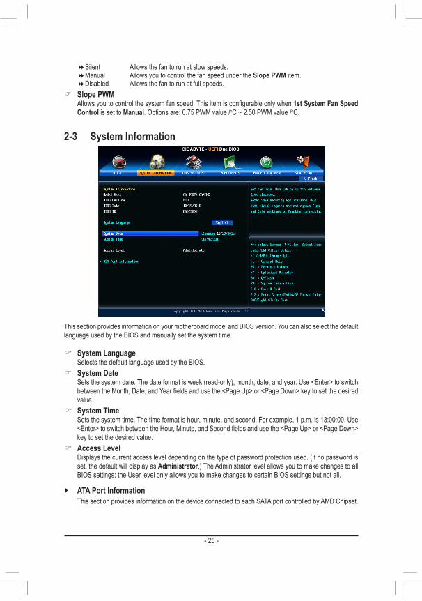
2-3 System Information
This section provides information on your motherboard model and BIOS version. You can also select the default language used by the BIOS and manually set the system time.
& System Language Selects the default language used by the BIOS.
& System Date Setsthesystemdate.Thedateformatisweek(read-only),month,date,andyear.Use<Enter>toswitch
betweentheMonth,Date,andYearfieldsandusethe<PageUp>or<PageDown>keytosetthedesiredvalue.
& System Time Sets the system time. The time format is hour, minute, and second. For example, 1 p.m. is 13:00:00. Use
<Enter>toswitchbetweentheHour,Minute,andSecondfieldsandusethe<PageUp>or<PageDown>key to set the desired value.
& Access Level Displaysthecurrentaccessleveldependingonthetypeofpasswordprotectionused.(Ifnopasswordis
set, the default will display as Administrator.) The Administrator level allows you to make changes to all BIOS settings; the User level only allows you to make changes to certain BIOS settings but not all.
` ATA Port Information ThissectionprovidesinformationonthedeviceconnectedtoeachSATAportcontrolledbyAMDChipset.
�Silent Allows the fan to run at slow speeds. �Manual Allows you to control the fan speed under the Slope PWM item. �Disabled Allowsthefantorunatfullspeeds.
& Slope PWM Allowsyoutocontrolthesystemfanspeed.Thisitemisconfigurableonlywhen1st System Fan Speed
Control is set to Manual. Options are: 0.75 PWM value /oC ~ 2.50 PWM value /oC.
- 25 -

& Boot Option Priorities Specifiestheoverallbootorderfromtheavailabledevices.RemovablestoragedevicesthatsupportGPT
formatwillbeprefixedwith"UEFI:"stringonthebootdevicelist.TobootfromanoperatingsystemthatsupportsGPTpartitioning,selectthedeviceprefixedwith"UEFI:"string.
Or if you want to install an operating system that supports GPT partitioning such as Windows 7 64-bit, select theopticaldrivethatcontainstheWindows764-bitinstallationdiskandisprefixedwith"UEFI:"string.
& Hard Drive/CD/DVD ROM Drive/Floppy Drive/Network Device BBS Priorities Specifiesthebootorderforaspecificdevicetype,suchasharddrives,opticaldrives,floppydiskdrives,
anddevicesthatsupportBootfromLANfunction,etc.Press<Enter>onthisitemtoenterthesubmenuthatpresents the devices of the same type that are connected. This item is present only if at least one device for this type is installed.
& Bootup NumLock State EnablesordisablesNumlockfeatureonthenumerickeypadofthekeyboardafterthePOST.(Default:
Enabled) & Security Option
Specifieswhetherapasswordisrequiredeverytimethesystemboots,oronlywhenyouenterBIOSSetup.Afterconfiguringthisitem,setthepassword(s)undertheAdministrator Password/User Password item.
�Setup A password is only required for entering the BIOS Setup program. �System A password is required for booting the system and for entering the BIOS Setup program.
(Default) & Full Screen LOGO Show
Allows you to determine whether to display the GIGABYTE Logo at system startup. Disabled skips the GIGABYTELogowhenthesystemstartsup.(Default:Enabled)
& Windows 8 Features Allowsyoutoselecttheoperatingsystemtobeinstalled.(Default:OtherOS)
2-4 BIOS Features
- 26 -

& CSM Support Enables or disables UEFI CSM (Compatibility Support Module) to support a legacy PC boot process.
�Always EnablesUEFICSM.(Default) �Never DisablesUEFICSMandsupportsUEFIBIOSbootprocessonly.
ThisitemisconfigurableonlywhenWindows 8 Features is set to Windows 8 or Windows 8 WHQL. & Boot Mode Selection
Allows you to select which type of operating system to boot. �UEFIandLegacy AllowsbootingfromoperatingsystemsthatsupportlegacyoptionROMorUEFI
optionROM.(Default) �LegacyOnly AllowsbootingfromoperatingsystemsthatonlysupportlegacyOptionROM. �UEFIOnly AllowsbootingfromoperatingsystemsthatonlysupportUEFIOptionROM.
ThisitemisconfigurableonlywhenCSM Support is set to Always. & LAN PXE Boot Option ROM
AllowsyoutoselectwhethertoenablethelegacyoptionROMfortheLANcontroller.(Default:Disabled) ThisitemisconfigurableonlywhenCSM Support is set to Always.
& Storage Boot Option Control AllowsyoutoselectwhethertoenabletheUEFIorlegacyoptionROMforthestoragedevicecontroller.
�Disabled DisablesoptionROM. �LegacyOnly EnableslegacyoptionROMonly.(Default) �UEFIOnly EnablesUEFIoptionROMonly. �LegacyFirst EnableslegacyoptionROMfirst. �UEFIFirst EnablesUEFIoptionROMfirst.
ThisitemisconfigurableonlywhenCSM Support is set to Always. & Other PCI Device ROM Priority
AllowsyoutoselectwhethertoenabletheUEFIorLegacyoptionROMforthePCIdevicecontrollerotherthan the LAN, storage device, and graphics controllers.
�LegacyOpROM EnableslegacyoptionROMonly. �UEFIOpROM EnablesUEFIoptionROMonly.(Default)
ThisitemisconfigurableonlywhenCSM Support is set to Always. & Network Stack
DisablesorenablesbootingfromthenetworktoinstallaGPTformatOS,suchasinstallingtheOSfromtheWindowsDeploymentServicesserver.(Default:Disable)
& Ipv4 PXE Support EnablesordisablesIPv4PXESupport.ThisitemisconfigurableonlywhenNetwork Stack is enabled.
& Ipv6 PXE Support EnablesordisablesIPv6PXESupport.ThisitemisconfigurableonlywhenNetwork Stack is enabled.
& Administrator Password Allowsyoutoconfigureanadministratorpassword.Press<Enter>onthisitem,typethepassword,and
thenpress<Enter>.Youwillberequestedtoconfirmthepassword.Typethepasswordagainandpress<Enter>.Youmustentertheadministratorpassword(oruserpassword)atsystemstartupandwhenenteringBIOSSetup.Differingfromtheuserpassword,theadministratorpasswordallowsyoutomakechangestoall BIOS settings.
& User Password Allowsyoutoconfigureauserpassword.Press<Enter>onthisitem,typethepassword,andthenpress
<Enter>.Youwillberequestedtoconfirmthepassword.Typethepasswordagainandpress<Enter>.You must enter the administrator password (or user password) at system startup and when entering BIOS Setup. However, the user password only allows you to make changes to certain BIOS settings but not all.
- 27 -

Tocancelthepassword,press<Enter>onthepassworditemandwhenrequestedforthepassword,enterthecorrectonefirst.Whenpromptedforanewpassword,press<Enter>withoutenteringanypassword.Press<Enter>againwhenpromptedtoconfirm.
NOTE:BeforesettingtheUserPassword,besuretosettheAdministratorPasswordfirst.
2-5 Peripherals
& Initial Display Output SpecifiesthefirstinitiationofthemonitordisplayfromtheinstalledPCIExpressgraphicscard.
�PCIe1Slot SetsthePCIExpressgraphicscardonthePCIEX16_1slotasthefirstdisplay.(Default) �PCIe2Slot SetsthePCIExpressgraphicscardonthePCIEX16_2slotasthefirstdisplay. �PCIe3Slot SetsthePCIExpressgraphicscardonthePCIEX4slotasthefirstdisplay.
& Audio LED EnablesordisablestheonboardaudioLEDfunction.
�Off Disablesthisfunction. �StillMode TheLEDsstayconstantlyon.(Default) �BeatMode ThebrightnessoftheLEDchangesaccordingtothemusicrhythm. �PulseMode ThebrightnessoftheLEDchangesslowlyandsmoothlylikebreath.
& OnChip SATA Controller EnablesordisablestheintegratedSATAcontrollers.(Default:Enabled)
& OnChip SATA Type EnablesordisablesRAIDfortheSATAcontrollersintegratedintheChipsetorconfigurestheSATAcontrollers
to AHCI mode. �NativeIDE ConfigurestheSATAcontrollertoIDEmode. �RAID EnablesRAIDfortheSATAcontroller. �AHCI ConfigurestheSATAcontrollerstoAHCImode.AdvancedHostController Interface
(AHCI)isaninterfacespecificationthatallowsthestoragedrivertoenableadvancedSerialATAfeaturessuchasNativeCommandQueuingandhotplug.(Default)
- 28 -

& OnChip SATA Port4/5 Type (SATA3 4/SATA3 5 connectors) ThisoptionisconfigurableonlywhenOnChip SATA Type is set to RAID or AHCI.Configurestheoperating
mode of the integrated SATA3 4~SATA3 5 connectors. �As SATA Type The mode depends on the OnChip SATA Type settings. �IDE ConfigurestheSATA34~SATA35connectorstoPATAmode.(Default)
& HD Audio Azalia Device Enablesordisablestheonboardaudiofunction.(Default:Enabled) If you wish to install a 3rd party add-in audio card instead of using the onboard audio, set this item to
Disabled. & USB DAC Power
EnablesordisablesthepowerfortheUSBDACconnectoronthebackpanel.ForaUSBDACthathasindependent power, set this item to Disabled.(Default:Enabled)
& Onboard USB Device EnablesordisablestheintegratedUSBcontroller.(Default:Enabled)
& Onboard LAN Controller EnablesordisablestheonboardLANfunction.(Default:Enabled) If you wish to install a 3rd party add-in network card instead of using the onboard LAN, set this item to
Disabled. & Onboard USB3.0 Controller (VIA® VL805 USB Controller)
Enables or disables the VIA®VL805USBcontroller.(Default:Enabled) & Onboard USB3.1 Controller (ASMedia® USB 3.1 Controller)
Enables or disables the ASMedia®USB3.1controller.(Default:Enabled) & Legacy USB Support
AllowsUSBkeyboard/mousetobeusedinMS-DOS.(Default:Enabled) & XHCI Hand-off
Determineswhether to enableXHCIHand-off feature for anoperating systemwithoutXHCIHand-offsupport.(Default:Enabled)
& EHCI Hand-off Determineswhether to enableEHCIHand-off feature for anoperating systemwithoutEHCIHand-off
support.(Default:Disabled) & Port 60/64 Emulation
Enables or disables emulation of I/O ports 64h and 60h. This should be enabled for full legacy support forUSBkeyboards/miceinMS-DOSorinoperatingsystemthatdoesnotnativelysupportUSBdevices.(Default:Disabled)
& USB Storage Devices DisplaysalistofconnectedUSBmassstoragedevices.ThisitemappearsonlywhenaUSBstoragedevice
is installed. & IOMMU Controller
EnablesordisablesAMDIOMMUsupport.(Default:Disabled) ` SBSATAConfiguration & SATA Hot Plug on PORT0~SATA Hot Plug on PORT5
EnablesordisablethehotplugcapabilityforeachSATAport.(Default:Disabled) & SATA Power on PORT0~SATA Power on PORT5
EnablesordisableseachSATAport.(Default:Enabled)
- 29 -

& Resume by Alarm Determineswhethertopoweronthesystematadesiredtime.(Default:Disabled) If enabled, set the date and time as following:
�Wakeupday:Turnonthesystemataspecifictimeoneachdayoronaspecificdayinamonth. �Wake up hour/minute/second: Set the time at which the system will be powered on automatically.
Note: When using this function, avoid inadequate shutdown from the operating system or removal of the AC power, or the settings may not be effective.
& HPET Support EnablesordisablesHighPrecisionEventTimer(HPET)forWindows10/8.1/7operatingsystem.(Default:
Enabled) & Soft-Off by PWR-BTTN
ConfiguresthewaytoturnoffthecomputerinMS-DOSmodeusingthepowerbutton. �Instant-Off Pressthepowerbuttonandthenthesystemwillbeturnedoffinstantly.(Default) �Delay4Sec. Pressandholdthepowerbuttonfor4secondstoturnoff thesystem.If thepower
button is pressed for less than 4 seconds, the system will enter suspend mode. & AC BACK
DeterminesthestateofthesystemafterthereturnofpowerfromanACpowerloss. �Memory The system returns to its last known awake state upon the return of the AC power. �Always On The system is turned on upon the return of the AC power. �AlwaysOff ThesystemstaysoffuponthereturnoftheACpower.(Default)
& Power On By Keyboard Allows the system to be turned on by a PS/2 keyboard wake-up event. Note: To use this function, you need an ATX power supply providing at least 1A on the +5VSB lead.
�Disabled Disablesthisfunction.(Default)
2-6 Power Management
` SuperIOConfiguration & Serial Port A
Enablesordisablestheonboardserialport.(Default:Enabled) ` NVMeConfiguration
DisplaysinformationonyourM.2NVMEPCIeSSDifinstalled.
- 30 -

�Password Set a password with 1~5 characters to turn on the system. �Keyboard98 PressPOWERbuttonontheWindows98keyboardtoturnonthesystem. �Any key Press any key to turn on the system.
& Power On Password Set the password when Power On By Keyboard is set to Password. Press<Enter>onthisitemandsetapasswordwithupto5charactersandthenpress<Enter>toaccept.
Toturnonthesystem,enterthepasswordandpress<Enter>. Note:Tocancelthepassword,press<Enter>onthisitem.Whenpromptedforthepassword,press<Enter>
again without entering the password to clear the password settings. & Power On By Mouse
Allows the system to be turned on by a PS/2 mouse wake-up event. Note: To use this function, you need an ATX power supply providing at least 1A on the +5VSB lead.
�Disabled Disablesthisfunction.(Default) �Move Move the mouse to turn on the system. �DoubleClick Doubleclickonleftbuttononthemousetoturnonthesystem.
& ErP DetermineswhethertoletthesystemconsumeleastpowerinS5(shutdown)state.(Default:Disabled) Note: When this item is set to Enabled,thefollowingfunctionswillbecomeunavailable:ResumebyAlarm,
PME event wake up, power on by mouse, power on by keyboard, and wake on LAN.
2-7 Save & Exit
& Save & Exit Setup Press<Enter>onthisitemandselectYes. This saves the changes to the CMOS and exits the BIOS Setup
program. Select Noorpress<Esc>toreturntotheBIOSSetupMainMenu. & Exit Without Saving
Press<Enter>onthisitemandselectYes. This exits the BIOS Setup without saving the changes made in BIOS Setup to the CMOS. Select Noorpress<Esc>toreturntotheBIOSSetupMainMenu.
- 31 -

& Load Optimized Defaults Press<Enter>onthisitemandselectYes to load the optimal BIOS default settings. The BIOS defaults
settings help the system to operate in optimum state. Always load the Optimized defaults after updating the BIOS or after clearing the CMOS values.
& Boot Override Allowsyoutoselectadevicetobootimmediately.Press<Enter>onthedeviceyouselectandselectYes
toconfirm.Yoursystemwillrestartautomaticallyandbootfromthatdevice. & SaveProfiles
ThisfunctionallowsyoutosavethecurrentBIOSsettingstoaprofile.Youcancreateupto8profilesandsaveasSetupProfile1~SetupProfile8.Press<Enter>tocomplete.OryoucanselectSelect File in HDD/FDD/USBtosavetheprofiletoyourstoragedevice.
& LoadProfiles If your system becomes unstable and you have loaded the BIOS default settings, you can use this function
to load theBIOSsettings fromaprofilecreatedbefore,without thehasslesof reconfiguring theBIOSsettings.Firstselecttheprofileyouwishtoloadandthenpress<Enter>tocomplete.YoucanselectSelect File in HDD/FDD/USBtoinputtheprofilepreviouslycreatedfromyourstoragedeviceorloadtheprofileautomatically created by the BIOS, such as reverting the BIOS settings to the last settings that worked properly (last known good record).
Chapter 3 Appendix
Before you begin, please prepare the following items: • AtleasttwoSATAharddrivesorM.2SSD(Note 1) (To ensure optimal performance, it is recommended that you use two hard drives with identical model and capacity). (Note 2)
• Windows setup disk. • Motherboard driver disk. • A USB thumb drive.
ConfiguringtheOnboardSATAControllerA. Installing SATA hard drive(s) in your computerConnect the SATA signal cables to SATA hard drives and the SATA ports on the motherboard. Then connect thepowerconnectorsfromyourpowersupplytotheharddrives.OrinstallyourM.2SSDintheM.2connectoron the motherboard.
3-1 ConfiguringaRAIDSetRAID Levels
(Note1) PleasenotethatanM.2PCIeSSDcannotbeusedtocreateaRAIDsetwithSATAdrive(s).(Note2) RefertoChapter1,"InternalConnectors,""M.2Socket3Connector,"fortheconfigurationtablesof
SATAharddrivesandM.2SSDs.
RAID 0 RAID 1 RAID 5 RAID 10Minimum Number of Hard Drives
≥2 2 ≥3 ≥4
Array Capacity Number of hard drives * Size of the
smallest drive
Size of the smallest drive
(Number of hard drives -1) * Size of the smallest drive
(Number of hard drives/2) * Size of the
smallest driveFault Tolerance No Yes Yes Yes
- 32 -

C-1.UEFIRAIDConfigurationOnlyWindows10/8.164-bitsupportsUEFIRAIDconfiguration.Step 1:In BIOS Setup, go to BIOS Features and set Windows 8 Features to Windows 8 and CSM Support to Never. Save the changes and exit BIOS Setup.Step 2:Restartyourcomputerandpress<F12> toenter thebootdeviceconfigurationmenu.Use theupordownarrow key to select UEFI: Built-in EFI Shell.Press<Enter>toaccess.FollowthestepsbelowandenterthecommandstoaccesstheRAIDsetuputility.1. Enter drvcfg at Shellandpress<Enter>: Shell> drvcfg2. When Drv [XX] Ctrl [XX] Lang [eng] appears, enter the following commands at Shell again: Shell> drvcfg -s XX XX XXs are the values shown in the brackets after Drv and Ctrl above, which may vary by hard drives.Thenpress<Enter>toentertheRAIDsetuputility.Step 3:The Main MenuisthefirstscreenwhenyouentertheBIOSRAIDSetuputility.Usetheupordownarrowkeyto select Logical Drive Main Menuandpress<Enter>.Step 4:Tocreateanarray,press<Enter>onLogical Drive Create Menu.Step 5:Usable hard drives are listed on the Logical Drive Create Menu. Use the up or down arrow key to select the harddrivetobeincludedinthearrayandpressthe<Space>key.Theselectedharddriveswillbemarkedwith[X]. Then move to Basic Settingandpress<Enter>.Step 6:Usetheupordownarrowkeytomovetoandconfigureeachrequirediteminsequence.Aftercompleting,press<Enter>onStart To Create.Whenthemessage"AreYouSureToCreateLogicalDrive?"appears,press<Enter>tobegincreatingtheRAIDarrayor<Esc>tocancel.Whencompleted,amessagewhichsays"SuccessfulToCreateLogicalDrive"willappear.Press<Enter>tocomplete.Press<F10>toexittheRAIDsetuputility.
B.ConfiguringSATAcontrollermodeinBIOSSetupMakesuretoconfiguretheSATAcontrollermodecorrectlyinsystemBIOSSetup.FortheBIOSSetupmenus,refertoChapter2,"BIOSSetup,""Peripherals."Steps:1. Turnonyourcomputerandpress<Delete>toenterBIOSSetupduringthePOST(Power-OnSelf-Test).Ensure
OnChip SATA Controller is enabled under Peripherals.ToenableRAIDfortheSATA30/1/2/3connectors,set OnChip SATA Type to RAID.ToenableRAIDfortheSATA34/SATA35connectors,setOnChip SATA Type to RAID and set OnChip SATA Port4/5 Type to As SATA Type.
2. Ifyouwant toconfigureUEFIRAID, followthesteps in"C-1."Toenter the legacyRAIDROM,savethesettingsandexitBIOSSetup.Referto"C-2"formoreinformation.
The BIOS Setup menus described in this section may differ from the exact settings for your motherboard. The actual BIOS Setup menu options you will see shall depend on the motherboard you have and the BIOS version.
- 33 -

PleasevisitGIGABYTE'swebsitefordetailsonconfiguringaRAIDarray.
Installing the SATA RAID/AHCI Driver and Operating SystemWith the correct BIOS settings, you are ready to install the operating system.
Installing the Operating System(The following instructions use Windows 8.1 as the example operating system.)Step 1:YouneedtoinstalltheSATARAID/AHCIdriverduringtheOSinstallation.UseanalternativesystemtocopytheSATARAID/AHCIdriverfromthemotherboarddriverdisktoaUSBflashdrive.CopytheHw8 folder under BootDrv in the driver disk.Step 2:Boot from the Windows 8.1 setup disk and perform standard OS installation steps. When the screen requesting you to load the driver appears, select Browse.Step 3:ThenbrowsetotheUSBflashdriveandselectthelocationofthedriver.Thelocationsofthedriversareasfollows:RAIDdriverforWindows8.132-bit:Hw8\RAID\x86 RAIDdriverforWindows8.164-bit:Hw8\RAID\x64AHCIdriverforWindows8.132-bit:Hw8\AHCI\W8 AHCIdriverforWindows8.164-bit:Hw8\AHCI\W864AFor Windows 7, browse to the Hw7 folder.Step 4:When a screen appears, select AMD-RAID Controller and click Next to load the driver and continue the OS installation.
C-2.ConfiguringLegacyRAIDROMEntertheRAIDBIOSsetuputilitytoconfigureaRAIDarray.SkipthisstepifyoudonotwanttocreateRAIDarray on the SATA controller.Steps:After the POST memory test begins and before the operating system boot begins, look for a message which says"Press<Ctrl-F>toenterRAIDOptionROMUtility".Press<Ctrl>+<F>toentertheRAIDBIOSsetuputility.Tocreateanewarray,press<2>toentertheLD View Menuwindow.Tocreateanarray,press<Ctrl+C>toaccess the LDDefineMenu.In the LDDefineMenu,usetheupordownarrowkeytomovetoanitemforfurtherconfiguration.
- 34 -

• Before installing the drivers, first install the operating system. (The following instructions useWindows 8.1 as the example operating system.)
• After installing the operating system, insert the motherboard driver disk into your optical drive. Click onthemessage"Taptochoosewhathappenswiththisdisc"onthetop-rightcornerofthescreenandselect"RunRun.exe."(OrgotoMyComputer,double-clicktheopticaldriveandexecutetheRun.exeprogram.)
3-2 Drivers Installation
Afterinsertingthedriverdisk,"XpressInstall"willautomaticallyscanyoursystemandthenlistallthedriversthatare recommended to install. You can click the Install Allbuttonand"XpressInstall"willinstallalltherecommendeddrivers. Or click Install Single Items to manually select the drivers you wish to install.
Please visit GIGABYTE's website for more software information.
PleasevisitGIGABYTE'swebsitefordetailsonconfiguringtheaudiosoftware.
- 35 -

3-3 Debug LED Codes
Code Description
10 PEI Core is started.
11 Pre-memory CPU initialization is started.
12~14 Reserved.
15 Pre-memory North-Bridge initialization is started.
16~18 Reserved.
19 Pre-memory South-Bridge initialization is started.
1A~2A Reserved.
2B~2F Memory initialization.
31 Memory installed.
32~36 CPU PEI initialization.
37~3A IOH PEI initialization.
3B~3E PCH PEI initialization.
3F~4F Reserved.
60 DXECoreisstarted.
61 NVRAMinitialization.
62 Installation of the PCH runtime services.
63~67 CPUDXEinitializationisstarted.
68 PCI host bridge initialization is started.
69 IOHDXEinitialization.
6A IOH SMM initialization.
6B~6F Reserved.
70 PCHDXEinitialization.
71 PCH SMM initialization.
72 PCH devices initialization.
73~77 PCHDXEinitialization(PCHmodulespecific).
78 ACPI Core initialization.
79 CSM initialization is started.
7A~7F ReservedforAMIuse.
80~8F ReservedforOEMuse(OEMDXEinitializationcodes).
90 PhasetransfertoBDS(BootDeviceSelection)fromDXE.
91 Issue event to connect drivers.
Regular Boot
- 36 -

Code Description
92 PCI Bus initialization is started.
93 PCI Bus hot plug initialization.
94 PCI Bus enumeration for detecting how many resources are requested.
95 Check PCI device requested resources.
96 Assign PCI device resources.
97 Console Output devices connect (ex. Monitor is lighted).
98 Console input devices connect (ex. PS2/USB keyboard/mouse are activated).
99 Super IO initialization.
9A USB initialization is started.
9B Issue reset during USB initialization process.
9C DetectandinstallallcurrentlyconnectedUSBdevices.
9D Activated all currently connected USB devices.
9E~9F Reserved.
A0 IDEinitializationisstarted.
A1 IssueresetduringIDEinitializationprocess.
A2 DetectandinstallallcurrentlyconnectedIDEdevices.
A3 ActivatedallcurrentlyconnectedIDEdevices.
A4 SCSI initialization is started.
A5 Issue reset during SCSI initialization process.
A6 DetectandinstallallcurrentlyconnectedSCSIdevices.
A7 Activated all currently connected SCSI devices.
A8 Verify password if needed.
A9 BIOS Setup is started.
AA Reserved.
AB Wait user command in BIOS Setup.
AC Reserved.
AD IssueReadyToBooteventforOSBoot.
AE Boot to Legacy OS.
AF Exit Boot Services.
B0 RuntimeAPinstallationbegins.
B1 RuntimeAPinstallationends.
B2 LegacyOptionROMinitialization.
B3 System reset if needed.
- 37 -

Code Description
B4 USB device hot plug-in.
B5 PCI device hot plug.
B6 Clean-upofNVRAM.
B7 ReconfigureNVRAMsettings.
B8~BF Reserved.
C0~CF Reserved.
Code Description
E0 S3Resumeisstarted(calledfromDXEIPL).
E1 Fill boot script data for S3 resume.
E2 Initializes VGA for S3 resume.
E3 OS S3 wake vector call.
S3 Resume
Code Description
F0 Recoverymodewillbetriggeredduetoinvalidfirmwarevolumedetection.
F1 Recoverymodewillbetriggeredbyuserdecision.
F2 Recoveryisstarted.
F3 Recoveryfirmwareimageisfound.
F4 Recoveryfirmwareimageisloaded.
F5~F7 ReservedforfutureAMIprogresscodes.
Recovery
Code Description
50~55 Memory initialization error occurs.
56 Invalid CPU type or speed.
57 CPU mismatch.
58 CPU self test failed or possible CPU cache error.
59 CPU micro-code is not found or micro-code update is failed.
5A Internal CPU error.
5B ResetPPIisfailed.
5C~5F Reserved.
D0 CPU initialization error.
D1 IOH initialization error.
Error
- 38 -

Code Description
D2 PCH initialization error.
D3 Some of the Architectural Protocols are not available.
D4 PCIresourceallocationerror.OutofResources.
D5 NoSpaceforLegacyOptionROMinitialization.D6 NoConsoleOutputDevicesarefound.D7 NoConsoleInputDevicesarefound.
D8 It is an invalid password.
D9~DA Can't load Boot Option.
DB Flash update is failed.
DC Resetprotocolisfailed.
DE~DF Reserved.
E8 S3 resume is failed.
E9 S3ResumePPIisnotfound.
EA S3ResumeBootScriptisinvalid.
EB S3 OS Wake call is failed.
EC~EF Reserved.
F8 RecoveryPPIisinvalid.
<F9> Recoverycapsuleisnotfound.
FA Invalid recovery capsule.
FB~FF Reserved.
- 39 -

Regulatory Statements
Regulatory NoticesThis document must not be copied without our written permission, and the contents there of must not be imparted to a third party nor be used for any unauthorized purpose.Contravention will be prosecuted. We believe that the information contained herein was accurate in all respects at the time of printing. GIGABYTE cannot, however, assume any responsibility for errors or omissions in this text. Also note that the information in this document is subject to change without notice and should not be construed as a commitment by GIGABYTE.
Our Commitment to Preserving the EnvironmentIn addition to high-efficiencyperformance, allGIGABYTEmotherboards fulfillEuropeanUnion regulationsforRoHS(RestrictionofCertainHazardousSubstancesinElectricalandElectronicEquipment)andWEEE(Waste Electrical and Electronic Equipment) environmental directives, as well as most major worldwide safety requirements. To prevent releases of harmful substances into the environment and to maximize the use of our natural resources, GIGABYTE provides the following information on how you can responsibly recycle or reuse mostofthematerialsinyour"endoflife"product.
Restriction of Hazardous Substances (RoHS) Directive StatementGIGABYTEproductshavenotintendedtoaddandsafefromhazardoussubstances(Cd,Pb,Hg,Cr+6,PBDEandPBB).ThepartsandcomponentshavebeencarefullyselectedtomeetRoHSrequirement.Moreover,weatGIGABYTE are continuing our efforts to develop products that do not use internationally banned toxic chemicals.
Waste Electrical & Electronic Equipment (WEEE) Directive StatementGIGABYTEwillfulfillthenationallawsasinterpretedfromthe2002/96/ECWEEE(WasteElectricalandElectronicEquipment)directive.TheWEEEDirectivespecifiesthetreatment,collection,recyclinganddisposalofelectricandelectronicdevicesandtheircomponents.UndertheDirective,usedequipmentmustbemarked,collectedseparately, and disposed of properly.
WEEE Symbol StatementThe symbol shown below is on the product or on its packaging, which indicates that this product must not be disposed of with other waste. Instead, the device should be taken to the waste collection centers for activation of the treatment, collection, recycling and disposal procedure. The separate collection and recycling of your waste equipment at the time of disposal will help to conserve natural resources and ensure that it is recycled in a manner that protects human health and the environment.
For more information about where you can drop off your waste equipment for recycling, please contact your localgovernmentoffice,yourhouseholdwastedisposalserviceorwhereyoupurchasedtheproductfordetailsof environmentally safe recycling.
� Whenyourelectricalorelectronicequipmentisnolongerusefultoyou,"takeitback"toyourlocalorregionalwaste collection administration for recycling.
� Ifyouneedfurtherassistanceinrecycling,reusinginyour"endoflife"product,youmaycontactusattheCustomer Care number listed in your product's user's manual and we will be glad to help you with your effort.
Finally, we suggest that you practice other environmentally friendly actions by understanding and using the energy-saving features of this product (where applicable), recycling the inner and outer packaging (including shipping containers) this product was delivered in, and by disposing of or recycling used batteries properly. With your help, we can reduce the amount of natural resources needed to produce electrical and electronic equipment,minimizetheuseoflandfillsforthedisposalof"endoflife"products,andgenerallyimproveourquality of life by ensuring that potentially hazardous substances are not released into the environment and are disposed of properly.
- 40 -

FCC Notice (U.S.A. Only)This equipment has been tested and found to comply with the limits for a Class B digital device, pursuant to Part 15oftheFCCRules.Theselimitsaredesignedtoprovidereasonableprotectionagainstharmfulinterferencein a residential installation. This equipment generates, uses, and can radiate radio frequency energy and, if not installed and used in accordance with the instructions, may cause harmful interference to radio communications. However, there is no guarantee that interference will not occur in a particular installation. If this equipment does cause harmful interference to radio or television reception, which can be determined by turning the equipment off and on, the user is encouraged to try to correct the interference by one or more of the following measures:
� Reorientorrelocatethereceivingantenna. � Increase the separation between the equipment and receiver. � Connect the equipment into an outlet on a circuit different from that to which the receiver is connected. � Consult a dealer or experienced TV/radio technician for help.
Canada, Industry Canada (IC) Notices / Canada, avis d'Industry Canada (IC) � ThisClassBdigitalapparatuscomplieswithCanadianICES-003andRSS-210. � Operation is subject to the following two conditions: (1) this device may not cause interference, and (2) this
device must accept any interference, including interference that may cause undesired operation of the device. � CetappareilnumériquedeclasseBestconformeauxnormescanadiennesICES-003etRSS-210. � Son fonctionnement est soumis aux deux conditions suivantes : (1) cet appareil ne doit pas causer
d'interférence et (2) cet appareil doit accepter toute interférence, notamment les interférences qui peuvent affecter son fonctionnement.
- 41 -

- 42 -

- 43 -

Contact Us
GIGA-BYTE TECHNOLOGY CO., LTD.Address:No.6,BaoqiangRd.,XindianDist.,NewTaipeiCity231,TaiwanTEL: +886-2-8912-4000, FAX: +886-2-8912-4005Tech. and Non-Tech. Support (Sales/Marketing) : http://esupport.gigabyte.comWEB address (English): http://www.gigabyte.comWEB address (Chinese): http://www.gigabyte.tw
• GIGABYTE eSupportTo submit a technical or non-technical (Sales/Marketing) question, please link to: http://esupport.gigabyte.com
- 44 -