GA-H81TN GA-B85TN GA-H87TN GA-Q87TN - Gigabyte
52
GA-H81TN GA-B85TN GA-H87TN GA-Q87TN User's Manual 12ME0-H81TN0-00R
-
Upload
khangminh22 -
Category
Documents
-
view
0 -
download
0
Transcript of GA-H81TN GA-B85TN GA-H87TN GA-Q87TN - Gigabyte

GA-H81TNGA-B85TNGA-H87TNGA-Q87TN
User's Manual12ME0-H81TN0-00R

Sept. 23, 2013
Motherboard
GA-H81TN
MotherboardGA-H81TN
Sept. 23, 2013
Sept. 23, 2013
Motherboard
GA-B85TN
MotherboardGA-B85TN
Sept. 23, 2013

Sept. 23, 2013
Motherboard
GA-H87TN
MotherboardGA-H87TN
Sept. 23, 2013
Sept. 23, 2013
Motherboard
GA-Q87TN
MotherboardGA-Q87TN
Sept. 23, 2013

Copyright
© 2015 GIGA-BYTE TECHNOLOGY CO., LTD. All rights reserved.The trademarks mentioned in this manual are legally registered to their respective owners.
Disclaimer
Information in this manual is protected by copyright laws and is the property of GIGABYTE. Changes to the specifications and features in this manual may be made by GIGABYTE without prior notice. No part of this manual may be reproduced, copied, translated, transmitted, or published in any form or by any means without GIGABYTE's prior written permission.
Documentation Classifications
In order to assist in the use of this product, GIGABYTE provides the following types of documentations: � For detailed product information, carefully read the User's Manual.
For product-related information, check on our website at: http://www.gigabyte.com

- 5 -
Table of Contents
Box Contents ...................................................................................................................6GA-H81TN/GA-B85TN/GA-H87TN Motherboard Layout ................................................7GA-Q87TN Motherboard Layout .....................................................................................8
Chapter 1 Hardware Installation .....................................................................................91-1 Installation Precautions .................................................................................... 91-2 ProductSpecifications .................................................................................... 101-3 Installing the CPU and CPU Cooler ............................................................... 131-4 Installing the Memory/Expansion Card .......................................................... 131-5 Back Panel Connectors .................................................................................. 141-6 Internal Connectors ........................................................................................ 16
Chapter 2 BIOS Setup ..................................................................................................292-1 The Main Menu .............................................................................................. 312-2 Advanced Menu ............................................................................................. 33
2-2-1 CPUConfiguration ..................................................................................................342-2-2 SATAConfiguration.................................................................................................362-2-3 Trusted Computing .................................................................................................372-2-4 Intel (R) Rapid Start Technology .............................................................................382-2-5 Intel(R) Smart Connect Technology ........................................................................392-2-6 AMTConfiguration ..................................................................................................402-2-7 SuperIOConfiguration ...........................................................................................412-2-8 H/W Monitor ............................................................................................................42
2-3 Chipset Menu ................................................................................................. 432-4 Boot Menu ...................................................................................................... 452-5 Security Menu ................................................................................................ 482-6 Save & Exit Menu ........................................................................................... 49

- 6 -
Box Contents ; GA-H81TN, GA-B85TN, GA-H87TN or GA-Q87TN motherboard ; Motherboard driver disk ; User's Manual ; I/O Shield (AIO Thin Mini-ITX x1, Standard Type x 1) ; Screws kit for expansion cards ; COM serial cable ; Cable SATA Power x 1
• The box contents above are for reference only and the actual items shall depend on the product package you obtain.

- 7 -
Socket 1150
PCIE4X
Intel® H81j/B85kH87l
CODEC
ATX_19V
GA-H81TNGA-B85TNGA-H87TN
FUSB
2_3
SATAIII_1 FUSB3 l
SATA_3kl
HDMI
EXT_CON
DMIC_CON
LPT
CLR_CMOS
FP_A
UDIO
SPKRMIC_IN
LINE_OUT
BATTERY
BIOSUSBX_1
USB3_1
DP
LAN
DC_INFUSB2_5
SATAIII_0
SATA_2
SYS_FAN
SATA_PWR
MPCI
E1X
SO_DIMM1
SO_DIMM2
WF_
LED
BL_S
W
FPD
LVDS
SYS_PANEL
MON_
SW
CPU_FAN
COM1
FPD_
PWR
LCD_
VCC
GA-H81TN/GA-B85TN/GA-H87TN Motherboard Layout
FUSB
2_2
FUSB
2_4
j Only for GA-H81TN. k Only for GA-B85TN. l Only for GA-H87TN.
(Note) The chip is located on the back of the motherboard.
Realt
ek®
GbE
LAN
(Note
)

- 8 -
GA-Q87TN
GA-Q87TN Motherboard Layout
Socket 1150
PCIE4X
Intel® Q87
CODEC
ATX_19V
FUSB
2_3
SATAIII_1 FUSB3 Intel® GbE LAN (Note)
SATAIII_3
HDMI
EXT_CON
DMIC_CON
LPT
CLR_CMOS
FP_A
UDIO
SPKRMIC_IN
LINE_OUT
BATTERY
BIOSUSBX_1
USB3_1
DP
LAN
LAN
DC_INFUSB2_5
SATAIII_0
SATAIII_2
SYS_FAN
SATA_PWR
MPCI
E1X
SO_DIMM1
SO_DIMM2
FPD
LVDS
SYS_PANEL
MON_
SW
CPU_FAN
COM1
Realt
ek®
GbE
LAN
(Note
)
FUSB
2_2
FUSB
2_4
(Note) The chip is located on the back of the motherboard.
WF_
LED
BL_S
WFP
D_PW
RLC
D_VC
C

- 9 -
1-1 Installation PrecautionsThe motherboard contains numerous delicate electronic circuits and components which can become damaged as a result of electrostatic discharge (ESD). Prior to installation, carefully read the user's manual and follow these procedures:
• Prior to installation, make sure the chassis is suitable for the motherboard. • Prior to installation, do not remove or break motherboard S/N (Serial Number) sticker or
warranty sticker provided by your dealer. These stickers are required for warranty validation. • Always remove the AC power by unplugging the power cord from the power outlet before
installing or removing the motherboard or other hardware components. • When connecting hardware components to the internal connectors on the motherboard,
make sure they are connected tightly and securely. • When handling the motherboard, avoid touching any metal leads or connectors. • It is best to wear an electrostatic discharge (ESD) wrist strap when handling electronic
components such as a motherboard, CPU or memory. If you do not have an ESD wrist strap,keepyourhandsdryandfirsttouchametalobjecttoeliminatestaticelectricity.
• Prior to installing the motherboard, please have it on top of an antistatic pad or within an electrostatic shielding container.
• Before unplugging the power supply cable from the motherboard, make sure the power supply has been turned off.
• Before turning on the power, make sure the power supply voltage has been set according to the local voltage standard.
• Before using the product, please verify that all cables and power connectors of your hardware components are connected.
• To prevent damage to the motherboard, do not allow screws to come in contact with the motherboard circuit or its components.
• Make sure there are no leftover screws or metal components placed on the motherboard or within the computer casing.
• Do not place the computer system on an uneven surface. • Do not place the computer system in a high-temperature environment. • Turning on the computer power during the installation process can lead to damage to
system components as well as physical harm to the user. • If you are uncertain about any installation steps or have a problem related to the use of the product,pleaseconsultacertifiedcomputertechnician.
Chapter 1 Hardware Installation

- 10 -
1-2 ProductSpecifications
j Only for GA-H81TN. k Only for GA-B85TN. l Only for GA-H87TN. P Only for GA-Q87TN.
CPU � Support for Intel® Core™ i7 processors/Intel® Core™ i5 processors/Intel® Core™ i3 processors/Intel® Pentium® processors/Intel® Celeron® processors in the LGA1150 package (Supports up to 84W)
(Go to GIGABYTE's website for the latest CPU support list.) � L3 cache varies with CPU
Chipset � Intel® H81j/B85k/H87l/Q87P Express ChipsetMemory � 2 x 1.5V DDR3 SO-DIMM sockets supporting up to 16GB(8GB X2) of system memory
* Due to a Windows 32-bit operating system limitation, when more than 4 GB of physical memory is installed, the actual memory size displayed will be less than the size of the physical memory installed.
� Dual channel memory architecture � Support for DDR3 1600/1333 MHz memory modules
(Go to GIGABYTE's website for the latest supported memory speeds and memory modules.)
Onboard Graphics � Chipset: - 1 x HDMI 1.4 port, supporting a maximum resolution of 4096x2160 - 1 x DisplayPort, supporting a maximum resolution of 2560x1600 - 1 x LVDS connector
Audio � Realtek® ALC887 codec � HighDefinitionAudio � 2/4/5.1/7.1-channel
* To configure5.1/7.1-channel audio, youhave touseanHD front panel audiomodule and enable the multi-channel audio feature through the audio driver.
LAN � 1 x Realtek® GbE LAN chip (10/100/1000 Mbit) (LAN1) jklP � 1 x Intel® GbE LAN chip (10/100/1000 Mbit) (LAN2) P
Expansion Slots � 1 x PCI Express x4 slot (Supports 25W only) (The PCIEX4 slot conforms to PCI Express 3.0 standard.)
� 1 x Mini PCI Express x1 slotStorage Interface � Chipset:
- 2 x SATA 6Gb/s connectors (SATAIII 0/1); 1 x SATA 3Gb/s connector (SATAII 2) j
- 3 x SATA 6Gb/s connectors (SATAIII 0/1/3); 1 x SATA 3Gb/s connector (SATAII 2) k
- 4 x SATA 6Gb/s connectors (SATAIII 0/1/2/3) lP - 1 x mSATA connector

- 11 -
USB � Chipset: - 2 x USB 3.0/2.0 ports; 7 x USB 2.0/1.1 ports j - 4 x USB 3.0/2.0 ports; 5 x USB 2.0/1.1 ports k - 6 x USB 3.0/2.0 ports; 5 x USB 2.0/1.1 ports lP
* USB 2.0/1.1 ports available through the internal USB headers (Card reader/Touch panel/webcam and other devices)
Internal Connectors
� 1 x 2-pin power connector � 1 x CPU fan header � 1 x system fan header � 2 x SATA 6Gb/s connectors j � 3 x SATA 6Gb/s connectors k � 4 x SATA 6Gb/s connectors lP � 1 x SATA 3Gb/s connector jk � 1 x mSATA connector � 1 x SATA power connector � 4 x USB 2.0/1.1 headers � 1 x serial port header � 1 x parallel port header � 1 x front panel header � 1 x front panel audio header � 1 x digital microphone header � 1 x AIO speaker header � 1 x LVDS connector � 1 x LVDS drive voltage header � 1xflatpaneldisplaypowerheader(bothpanelandbacklightinverter) � 1xflatpaneldisplaypowerconnector � 1 x backlight switch header � 1xflatpaneldisplayswitchheader � 1 x WIFI activity indicator LED header � 1xClearCMOSjumper
Back Panel Connectors
� 1 x HDMI port � 1 x DisplayPort � 4 x USB 3.0/2.0 ports klP � 2 x USB 3.0/2.0 ports j � 2 x USB 2.0/1.1 ports j � 1 x RJ-45 port jkl � 2 x RJ-45 ports P � 2xaudiojacks(LineOut,MicIn) � 1 x DC-In power connector
j Only for GA-H81TN. k Only for GA-B85TN. l Only for GA-H87TN. P Only for GA-Q87TN.

- 12 -
I/O Controller � Nuvoton I/O Controller Chip
Hardware Monitor � System voltage detection � CPU/System temperature detection � CPU/System fan speed detection � CPU fan speed control
* For 4-pin CPU coolers only. * Whether the CPU fan speed control function is supported will depend on the CPU
cooler you install.BIOS � 1x64Mbitflashj
� 1x128MbitflashklP � Use of licensed AMI UEFI BIOS � PnP 1.0a, DMI 2.7, WfM 2.0, SM BIOS 2.7, ACPI 5.0
Operating System � Support for Windows 8/7
Form Factor � Thin Mini-ITX Form Factor; 17.0cm x 17.0cm* GIGABYTEreservestherighttomakeanychangestotheproductspecificationsandproduct-relatedinformationwithout
prior notice.
j Only for GA-H81TN. k Only for GA-B85TN. l Only for GA-H87TN. P Only for GA-Q87TN.
• GIGABYTE recommends 180W power adapters for processors above 84W TDP. Processors with a TDP lower than 84W, may use 150W power adapters.
• Power adapter connector dimension: 7.4 x 5.1mm, 180W = 19V / 9.47A, 150W = 19V / 7.89A.

- 13 -
1-3 Installing the CPU and CPU CoolerRead the following guidelines before you begin to install the CPU/CPU cooler: • Make sure that the motherboard supports the CPU.
(Go to GIGABYTE's website for the latest CPU support list.) • Always turn off the computer and unplug the power cord from the power outlet before installing
the CPU to prevent hardware damage. • Locate the pin one of the CPU. The CPU cannot be inserted if oriented incorrectly. (Or you may
locate the notches on both sides of the CPU and alignment keys on the CPU socket.) • Apply an even and thin layer of thermal grease on the surface of the CPU. • Do not turn on the computer if the CPU cooler is not installed, otherwise overheating and
damage of the CPU may occur. • SettheCPUhostfrequencyinaccordancewiththeCPUspecifications.Itisnotrecommendedthatthesystembusfrequencybesetbeyondhardwarespecificationssinceitdoesnotmeetthestandard requirements for the peripherals. If you wish to set the frequency beyond the standard specifications,pleasedosoaccordingtoyourhardwarespecificationsincludingtheCPU,graphics card, memory, hard drive, etc.
• For installing the CPU cooler, please refer to chassis user's manual.
1-4 Installing the Memory/Expansion CardRead the following guidelines before you begin to install the memory expansion card: • Make sure that the motherboard supports the memory. It is recommended that memory of the
same capacity, brand, speed, and chips be used. (Go to GIGABYTE's website for the latest supported memory speeds and memory modules.)
• Make sure the motherboard supports the expansion card. Carefully read the manual that came with your expansion card.
• Always turn off the computer and unplug the power cord from the power outlet before installing the memory/expansion card to prevent hardware damage.
• Memory modules have a foolproof design. A memory module can be installed in only one direction. If you are unable to insert the memory, switch the direction.
- 14 -
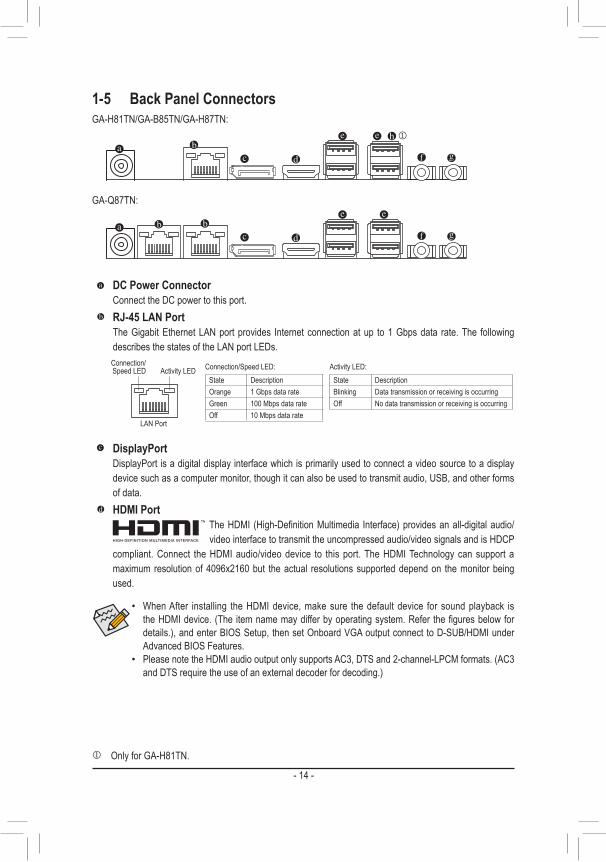
1-5 Back Panel Connectors
DC Power ConnectorConnect the DC power to this port.RJ-45 LAN PortThe Gigabit Ethernet LAN port provides Internet connection at up to 1 Gbps data rate. The following describes the states of the LAN port LEDs.
• When After installing the HDMI device, make sure the default device for sound playback is theHDMIdevice.(The itemnamemaydifferbyoperatingsystem.Refer thefiguresbelowfordetails.), and enter BIOS Setup, then set Onboard VGA output connect to D-SUB/HDMI under Advanced BIOS Features.
• Please note the HDMI audio output only supports AC3, DTS and 2-channel-LPCM formats. (AC3 and DTS require the use of an external decoder for decoding.)
DisplayPortDisplayPort is a digital display interface which is primarily used to connect a video source to a display device such as a computer monitor, though it can also be used to transmit audio, USB, and other forms of data. HDMI Port
TheHDMI (High-DefinitionMultimedia Interface)providesanall-digitalaudio/video interface to transmit the uncompressed audio/video signals and is HDCP
compliant. Connect the HDMI audio/video device to this port. The HDMI Technology can support a maximum resolution of 4096x2160 but the actual resolutions supported depend on the monitor being used.
Activity LEDConnection/Speed LED
LAN Port
Activity LED:Connection/Speed LED:State DescriptionOrange 1 Gbps data rateGreen 100 Mbps data rateOff 10 Mbps data rate
State DescriptionBlinking Data transmission or receiving is occurringOff No data transmission or receiving is occurring
GA-H81TN/GA-B85TN/GA-H87TN:
GA-Q87TN:
j
j Only for GA-H81TN.

- 15 -
• Whenremovingthecableconnectedtoabackpanelconnector,firstremovethecablefromyourdevice and then remove it from the motherboard.
• When removing the cable, pull it straight out from the connector. Do not rock it side to side to prevent an electrical short inside the cable connector.
USB 3.0/2.0/1.1 PortThe USB port supports the USB 3.0 specification. Use this port for USB devices such as a USB keyboard/mouse,USBprinter,USBflashdriveandetc.Line Out Jack (Green)ThedefaultLineOut (FrontSpeakerOut) jack.Stereospeakers,earphoneor frontsurroundspeakerscanbeconnectedtoLineOut(FrontSpeakerOut)jack.Mic In Jack (Pink)ThedefaultMICInjack.MicrophonecabbeconnectedtoMICInjack.USB 2.0/1.1 Port jThe USB port supports the USB 2.0 specification. Use this port for USB devices such as a USB keyboard/mouse,USBprinter,USBflashdriveandetc.
j Only for GA-H81TN.

- 16 -
1-6 Internal Connectors
Read the following guidelines before connecting external devices: • First make sure your devices are compliant with the connectors you wish to connect. • Before installing the devices, be sure to turn off the devices and your computer. Unplug the power cord from
the power outlet to prevent damage to the devices. • After installing the device and before turning on the computer, make sure the device cable has been securely
attached to the connector on the motherboard.
1) SYS_PANEL2) SATAIII_03) SATAIII_14) SATAIII_25) SATAIII_36) FUSB2_27) FUSB2_38) FUSB2_49) FUSB2_5
10) FUSB311) FP_AUDIO12) FPD13) LVDS14) CPU_FAN
15) SYS_FAN16) DMIC_CON17) ATX_19V18) MON_SW19) SATA_PWR20) SPKR21) BATTERY22) CLR_CMOS23) LCD_VCC24) FPD_PWR25) WF_LED26) BL_SW27) LPT28) COM1
21
14
5
31 2 10
13
15
4
7
20
27
28
116
8
9
12
1622
17
18
26
2324
25
19

- 17 -
The front panel design may differ by chassis. A front panel module mainly consists of power switch, reset switch, power LED, hard drive activity LED, speaker and etc. When connecting your chassis front panel module to this header, make sure the wire assignments and the pin assignments are matched correctly.
10
9
2
1
1) SYS_PANEL (Front Panel Header) Connect the power switch, reset switch, speaker, chassis intrusion switch/sensor and system status
indicator on the chassis to this header according to the pin assignments below. Note the positive and negative pins before connecting the cables.
2/3) SATAIII_0/1 (SATA 6Gb/s Connector) The SATA connectors conform to SATA 6Gb/s standard and are compatible with SATA 3Gb/s and SATA
1.5Gb/s standard. Each SATA connector supports a single SATA device.
1
SATAIII_0/1
7
DEBUG PORT
Pin No. Definition1 GND2 TXP3 TXN4 GND5 RXN6 RXP7 GND
Pin No. Signal Name Definition1 HD+ Hard Disk LED Signal anode (+)2 MPD+ Power LED Signal anode (+)3 HD- Hard Disk LED Signal cathode(-)4 MPD- Power LED Signal cathode(-)5 GND Ground6 PW+ Power Button anode (+)7 RST Reset Button8 PW- Power Button cathode(-)9 WF_LED WifiactiveLEDSignal
j Only for GA-H81TN. k Only for GA-B85TN. l Only for GA-H87TN. P Only for GA-Q87TN.

- 18 -
4) SATAIII_2 (SATA 6Gb/s Connector) Pl The SATA connectors conform to SATA 6Gb/s standard and are compatible with SATA 3Gb/s and SATA
1.5Gb/s standard. Each SATA connector supports a single SATA device. SATAIII_2 (SATA 3Gb/s Connector) jk The SATA connectors conform to SATA 3Gb/s standard and are compatible with SATA 1.5Gb/s standard.
Each SATA connector supports a single SATA device.
1
SATAIII_2
7
DEBUG PORT
Pin No. Definition1 GND2 TXP3 TXN4 GND5 RXN6 RXP7 GND
j Only for GA-H81TN. k Only for GA-B85TN. l Only for GA-H87TN. P Only for GA-Q87TN.
5) SATAIII_3 (SATA 6Gb/s Connector) klP The SATA connectors conform to SATA 6Gb/s standard and are compatible with SATA 3Gb/s and SATA
1.5Gb/s standard. Each SATA connector supports a single SATA device.
1
SATAIII_3
7
DEBUG PORT
Pin No. Definition1 GND2 TXP3 TXN4 GND5 RXN6 RXP7 GND

- 19 -
6/8/9) FUSB2_1/2/4/5 (USB Header) TheheadersconformtoUSB2.0/1.1specification.Eachheadersupportsasingledevice.
109
21
Pin No. Definition1 VCC2 VCC3 USB-4 USB-5 USB+6 USB+7 GND8 GND9 No Pin
10 NC
j Only for GA-H81TN. k Only for GA-B85TN. l Only for GA-H87TN. P Only for GA-Q87TN.
7) FUSB2_3 (USB Headers) TheheadersconformtoUSB2.0/1.1specification.EachUSBheadercanprovidetwoUSBportsviaan
optional USB bracket. For purchasing the optional USB bracket, please contact the local dealer.
1 5
1
5Pin No. Definition
1 VCC2 USB-3 USB+4 GND5 No Pin
FUSB2_2/FUSB2_4
FUSB2_5

- 20 -
12
910
11) FP_AUDIO (Front Panel Audio Header) The front panel audio header supports Intel®HighDefinitionaudio (HD)andAC'97audio.Youmay
connect your chassis front panel audio module to this header. Make sure the wire assignments of the module connector match the pin assignments of the motherboard header. Incorrect connection between the module connector and the motherboard header will make the device unable to work or even damage it.
• The front panel audio header supports HD audio by default. • Audio signals will be present on both of the front and back panel audio connections simultaneously. • Some chassis provide a front panel audio module that has separated connectors on each wire
instead of a single plug. For information about connecting the front panel audio module that has different wire assignments, please contact the chassis manufacturer.
Pin No. Definition1 F_MIC_L2 GND3 F_MIC_R4 GPIO_DET5 F_LINE_R6 F_MIC_JD7 GND8 No Pin9 F_LINE_L
10 F_LINE_JD
Prior to installing the USB bracket, be sure to turn off your computer and unplug the power cord from the power outlet to prevent damage to the USB bracket.
10) FUSB3 (USB 3.0/2.0 Header) TheheaderconformstoUSB3.0/2.0specificationandcanprovidetwoUSBports.Forpurchasingthe
optional 3.5" front panel that provides two USB 3.0/2.0 ports, please contact the local dealer.
Pin No. Definition Pin No. Definition1 VBUS 11 D2+2 SSRX1- 12 D2-3 SSRX1+ 13 GND4 GND 14 SSTX2+5 SSTX1- 15 SSTX2-6 SSTX1+ 16 GND7 GND 17 SSRX2+8 D1- 18 SSRX2-9 D1+ 19 VBUS
10 NC 20 No Pin
F_USB30F_�U������
�B_����
F_���������F_��������������
������������
10
11 20
1

- 21 -
12) FPD (Flat Panel Display Headers) The FPD is a high-speed interface connecting the output of a video controller in a laptop computer,
computer monitor or LCD television set to the display panel. Most laptops, LCD computer monitors and LCD TVs use this interface internally.
TheheadersconformtoFPDspecification.
1
8Pin No. Definition
1 BKLT_EN2 BKLT_PWM3 BKLT_PWR4 BKLT_PWR5 BKLT_GND/Brightness_GND6 BKLT_GND/Brightness_GND7 Brightness_Up8 Brightness_Down
13) LVDS (LVDS Header) LVDS stands for Low-voltage differential signaling, which uses high-speed analog circuit techniques to
provide multigigabit data transfers on copper interconnects and is a generic interface standard for high-speed data transmission.
1
40
Pin No. Definition Pin No. Definition1 ODD_Lane3_P 21 NC2 ODD_Lane3_N 22 EDID_3.3V3 ODD_Lane2_P 23 LCD_GND4 ODD_Lane2_N 24 LVDS SENSE (Note)
5 ODD_Lane1_P 25 LCD_GND6 ODD_Lane1_N 26 ODD_CLK_P7 ODD_Lane0_P 27 ODD_CLK_N8 ODD_Lane0_N 28 BLKT_GND9 EVEN_Lane3_P 29 BLKT_GND
10 EVEN_Lane3_N 30 BLKT_GND11 EVEN_Lane2_P 31 EDID_CLK12 EVEN_Lane2_N 32 BLKT_ENABLE13 EVEN_Lane1_P 33 BLKT_PWM_DIM14 EVEN_Lane1_N 34 EVEN_CLK_P15 EVEN_Lane0_P 35 EVEN_CLK_N16 EVEN_Lane0_N 36 BLKT_PWR17 EDID_GND 37 BLKT_PWR18 LCD_VCC 38 BLKT_PWR19 LCD_VCC 39 NC20 LCD_VCC 40 EDID_DATA
(Note) LVDS SENSE must link cable LCD Panel GND.

- 22 -
14/15) CPU_FAN/SYS_FAN (Fan Headers) All fan headers on this motherboard are 4-pin. Most fan headers possess a foolproof insertion design.
When connecting a fan cable, be sure to connect it in the correct orientation (the black connector wire is the ground wire). The speed control function requires the use of a fan with fan speed control design. For optimum heat dissipation, it is recommended that a system fan be installed inside the chassis.
• Be sure to connect fan cables to the fan headers to prevent your CPU and system from overheating. Overheating may result in damage to the CPU or the system may hang.
• Thesefanheadersarenotconfigurationjumperblocks.Donotplaceajumpercapontheheaders.
16) DMIC_CON (DMIC Headers) This header is for a digital microphone.
5
1
Pin No. Definition1 GND2 +12V3 Sense4 Speed Control
SYS_FAN
DEBU
G PO
RT
DEBUG PORT
1
1
CPU_FAN
Pin No. Definition1 Power2 DMI DATA 3 GND4 DMI CLK5 No Pin

- 23 -
17) ATX_19V (2 Pin Power Connector) This power connector is for the integrated 19V chassis power supply.
12
Pin No. Definition1 GND2 +19V
18) MON_SW (Flat panel display switch header) This header allows you to connect an on/off switch for the display.
1
Pin No. Definition1 Mon_SW2 GND

- 24 -
20) SPKR (Speaker Header) This speaker header is connected to a L/R audio pins from the board to support the 3W (4ohm) stereo
speaker on your AIO chassis.
1
4 Pin No. Definition1 Speaker OUT L-2 Speaker OUT L+3 Speaker OUT R+4 Speaker OUT R-
19) SATA_PWR (SATA Power Connector) This connector provides power to installed SATA devices.
Connect the included SATA power cable to the SATA_PWR connector. Then connect the SATA/optical drive power connectors to your hard drive and optical drive.

- 25 -
21) BATTERY (Battery Cable Connector) Thebatteryprovidespowertokeepthevalues(suchasBIOSconfigurations,date,andtimeinformation)
in the CMOS when the computer is turned off. Replace the battery when the battery voltage drops to a low level, or the CMOS values may not be accurate or may be lost.
• Always turn off your computer and unplug the power cord before replacing the battery. • Replace the battery with an equivalent one. Danger of explosion if the battery is replaced with an incorrect
model. • Contact the place of purchase or local dealer if you are not able to replace the battery by yourself or
uncertain about the battery model. • Used batteries must be handled in accordance with local environmental regulations.
12
Pin No. Definition1 RTC Reset2 GND
22) CLR_CMOS (Clearing CMOS Jumper) UsethisjumpertocleartheCMOSvalues(e.g.dateinformationandBIOSconfigurations)andresetthe
CMOSvalues to factorydefaults.Toclear theCMOSvalues,useametalobject likeascrewdriver totouch the two pins for a few seconds.
Open: Normal operation (Default setting)
Close: Clear CMOS data
• Always turn off your computer and unplug the power cord from the power outlet before clearing the CMOS values.
• After system restart, go to BIOS Setup to load factory defaults (select Load Optimized Defaults) or manuallyconfiguretheBIOSsettings(refertoChapter2,"BIOSSetup,"forBIOSconfigurations).

- 26 -
23) LCD_VCC (LVDS Drive Boltage Jumper) Thisjumpercanbeusedtoprovidedifferentscreenvoltagesettings.
1
1
1-2 Close: Set to 3V.
2-3 Close: Set to 5V. (Default setting)
24) FPD_PWR (Flat Panel Display Power Jumper) Thisjumperallowsyoutoselecttherequiredoperatingvoltageforthebacklightpanel.
1-2 Close: Set to 12V.
2-3 Close: Set to 19V. (Default setting)
1
1

- 27 -
25) WF_LED (WIFI Activity Indicator LED Header) This header allows you to connect a WiFi operation indicator LED.
1Pin No. Definition
1 GND2 LED_WLAN
26) BL_SW (Back Light Switch) TheBackLightswitchprovidesthefunctionforscreenbacklightadjustment.
1 Pin No. Definition1 BL_DOWN2 BL_UP

- 28 -
109
21
28) COM1 (Serial Port Header) The COM header can provide one serial port via an optional COM port cable. For purchasing the
optional COM port cable, please contact the local dealer.
Pin No. Definition1 NDCD-2 NDSR-3 NSIN4 NRTS-5 NSOUT6 NCTS-7 NDTR-8 NRI-9 GND
10 No Pin
27) LPT (Parallel Port Header) The LPT header can provide one parallel port via an optional LPT port cable. For purchasing the optional
LPT port cable, please contact the local dealer.
Pin No. Definition Pin No. Definition1 STB- 11 PD42 BUSY 12 INIT-3 PD0 13 PD54 PE 14 SLIN-5 PD1 15 PD66 SLCT 16 GND7 PD2 17 PD78 AFD- 18 GND9 PD3 19 ACK-
10 ERR- 20 GND
2019
21
DEBUG PORT

- 29 -
Chapter 2 BIOS SetupBIOS (Basic Input and Output System) records hardware parameters of the system in the CMOS on the motherboard.Itsmajorfunctions includeconductingthePower-OnSelf-Test(POST)duringsystemstartup,saving system parameters and loading operating system, etc. BIOS includes a BIOS Setup program that allows theusertomodifybasicsystemconfigurationsettingsortoactivatecertainsystemfeatures.Whenthepoweristurnedoff,thebatteryonthemotherboardsuppliesthenecessarypowertotheCMOStokeeptheconfigurationvalues in the CMOS.
To access the BIOS Setup program, press the <F2> key during the POST when the power is turned on.
• BIOSflashingispotentiallyrisky,ifyoudonotencounterproblemsofusingthecurrentBIOSversion,itisrecommendedthatyoudon'tflashtheBIOS.ToflashtheBIOS,doitwithcaution.InadequateBIOSflashingmayresultinsystemmalfunction.
• It is recommended that you not alter the default settings (unless you need to) to prevent system instability or other unexpected results. Inadequately altering the settings may result in system's failure to boot. If this occurs, try to clear the CMOS values and reset the board to default values. (Refer to the"RestoreDefaults"sectioninthischapterorintroductionsofthebattery/clearingCMOSjumperin Chapter 1 for how to clear the CMOS values.)
BIOS Setup Program Function Keys<h><i> Move the selection bar to select an item<f><g> Move the selection bar to select the screen<Enter> Execute command or enter the submenu<Esc> Main Menu: Exit the BIOS Setup program
Submenus: Exit current submenu <+> Increase the numeric value or make changes<-> Decrease the numeric value or make changes<F1> General Help<F2> Restore the previous BIOS settings for the current submenus<F3> Load the Optimized BIOS default settings for the current submenus<F4> Save all the changes and exit the BIOS Setup program

- 30 -
� Main This setup page includes all the items in standard compatible BIOS
� Advanced This setup page includes all the items of AMI BIOS special enhanced features. (ex:Autodetectfanandtemperaturestatus,automaticallyconfigureharddiskparameters.)
� Chipset NorthbridgeandSouthbridgeadditionalfeaturesconfiguration.
� Boot Thissetuppageprovidesitemsforconfigurationofbootsequence.
� Security Change,set,ordisablesupervisoranduserpassword.Configurationsupervisorpasswordallowsyouto
restrict access to the system and BIOS Setup. A supervisor password allows you to make changes in BIOS Setup. A user password only allows you to view the BIOS settings but not to make changes.
� Save & Exit Save all the changes made in the BIOS Setup program to the CMOS and exit BIOS Setup. (Pressing <F10>
can also carry out this task.) Abandonallchangesandtheprevioussettingsremainineffect.Pressing<Y>totheconfirmationmessage
will exit BIOS Setup. (Pressing <Esc> can also carry out this task.)

- 31 -
2-1 The Main MenuOnce you enter the BIOS Setup program, the Main Menu (as shown below) appears on the screen. Use arrow keys to move among the items and press <Enter> to accept or enter other sub-menu.
Main Menu HelpThe on-screen description of a highlighted setup option is displayed on the bottom line of the Main Menu.Submenu HelpWhile in a submenu, press <F1> to display a help screen (General Help) of function keys available for the menu. Press <Esc> to exit the help screen. Help for each item is in the Item Help block on the right side of the submenu.(Sample BIOS Version: MSQ87TN-SI F4a)
• When the system is not stable as usual, select the Restore Defaults item to set your system to its defaults.
• The BIOS Setup menus described in this chapter are for reference only and may differ by BIOS version.

- 32 -
& BIOS Information & Product Name
Display the information motherboard model. & BIOS Version
Display the BIOS version. & Build Date and Time
Displays the date and time when the BIOS setup utility was created. & LAN1/2 MAC Address
Displays the MAC address information.
& Memory Information & Size
Determines how much total memory is present during the POST. & Frequency
Display the memory frequency information.
& ME FW Version DisplaytheMEfirmwareversion.
& System Date Set the date following the weekday-month-day- year format.
& System Time Set the system time following the hour-minute- second format.

- 33 -
2-2 Advanced Menu
TheAdvancedmenudisplaysubmenuoptionsforconfiguringthefunctionofvarioushardwarecomponents.Select a submenu item, then press Enter to access the related submenu screen.

- 34 -
2-2-1 CPUConfiguration
& CPU Type Displays the processor type information.
& CPU Signature Displays the processor ID information.
& Microcode Patch Display the information of the processor microcode patch.
& CPU Speed Display the information of the processor speed.
& Processor Cores Display the information of the processor core.
& Intel HT Technology Display Intel Hyper Threading Technology function support information.
& Intel VT-x Technology Display Intel Virtualization Technology function support information.
& Intel SMX Technology Display Intel Safer Mode Extensions Technology function support information.
& 64-bit Display the supported infprmation of installed CPU.
& L1 Data Cache Display the information of L1 Data Cache.
& L1 Code Cache Display the information of L1 Code Cache.

- 35 -
& L2 Cache Display the information of L2 Cache per Core.
& L3 Cache Display the information of total L3 Cache per socket.
& Intel TXT(LT) Support (Note)
Enables or disables Intel® Trusted Execution Technology (Intel® TXT). Intel® Trusted Execution Technologyprovides a hardware-based security foundation. Default setting is Enabled.
& Intel Virtualization Technology (Note)
Select whether to enable the Intel Virtualization Technology function. VT allows a single platform to run multiple operating systems in independent partitions.
Options available: Enabled/Disabled. Default setting is Enabled. & EIST (Enhanced Intel SpeedStep Technology)
Conventional Intel SpeedStep Technology switches both voltage and frequency in tandem between high and low levels in response to processor load.
Options available: Enabled/Disabled. Default setting is Enabled. & Turbo Mode
When this feature is enabled, the processor can dynamically overclock one or two of its four processing cores to improve performance with applications that are not multi-threaded or optimized for quad-core processors.
Options available: Enabled/Disabled. Default setting is Enabled. & CPU C3/C6 Report (Note)
Allows you to determine whether to let the CPU enter C3/C6 mode in system halt state. When enabled, the CPU core frequency and voltage will be reduced during system halt state to decrease power consumption. The C3/C6 state is a more enhanced power-saving state than C1.
Options available: Enabled/Disabled. Default setting is Enabled. Default setting for C3 is Enabled. Default setting for C6 is Enabled.
& CPU C7 report (Note)
Allows you to determine whether to let the CPU enter C7 mode in system halt state. When enabled, the CPU core frequency and voltage will be reduced during system halt state to decrease power consumption. The C7 state is a more enhanced power-saving state than C3. Default setting is CPU C7s.
(Note) This item is present only when you install a CPU that supports this feature. For more information about Intel CPUs' unique features, please visit Intel's website.

- 36 -
2-2-2 SATAConfiguration
& SATA Mode Selection EnablesordisablesRAIDfortheSATAcontrollersintegratedintheIntelChipsetorconfigurestheSATA
controllers to AHCI mode. �IDE ConfigurestheSATAcontrollertoIDEmode. �AHCI ConfigurestheSATAcontrollerstoAHCImode.AdvancedHostControllerInterface(AHCI)
isaninterfacespecificationthatallowsthestoragedrivertoenableadvancedSerialATAfeatures such as Native Command Queuing and hot plug. (Default)
�RAID Enables RAID for the SATA controller. & Serial ATA Port 0/Serial ATA Port 1/Serial ATA Port 2/Serial ATA Port 3klP/mSATA(Note)
ThecategoryidentifiesSerialATAandmSATAtypesofharddiskthatareinstalledinthecomputer. System will automatically detect HDD type. Notethatthespecificationsofyourdrivemustmatchwiththedrivetable.Theharddiskwillnotworkproperly
if you enter improper information for this category. Hard drive information should be labeled on the outside device casing. Enter the appropriate option based
on this information. & Hot Plug
Enables or disable the hot plug capability for each SATA port. (Default: Disabled)
j Only for GA-H81TN. k Only for GA-B85TN. l Only for GA-H87TN. P Only for GA-Q87TN.
(Note) Advanced items prompt when this item is enabled.

- 37 -
2-2-3 Trusted Computing
& Security Device Support Option available: Enabled/Disabled. Default setting is Disabled.

- 38 -
2-2-4 Intel (R) Rapid Start Technology
& Intel(R) Rapid Start Technology(Note) Enable/Disable the Intel Rapid Start Technology (IRSTe) funciton. The IRSTe enables your system to get
up and running faster from even the deepest sleep, saving time and power consumption. Option available: Enabled/Disabled. Default setting is Disabled.
(Note) Advanced items prompt when this item is enabled.

- 39 -
2-2-5 Intel(R) Smart Connect Technology
& ISCTConfiguration Enables or disables Intel Smart Connect Technology. (Default: Disabled)

- 40 -
2-2-6 AMTConfiguration
This section allows you to enable/disable Intel Active Management Technology (Intel AMT) for remote computer managementonhardwarelevelandprovidesyouwithfurtherconfigurationoptions.

- 41 -
2-2-7 SuperIOConfiguration
& SuperIOConfiguration ThissectionprovidesinformationonthesuperI/Ochipandallowsyoutoconfiguretheserialportand
parallel port. & SerialPort0Configuration
Enables or disables the onboard serial port. (Default: Enabled) & ParallelPortConfiguration
Enables or disables the onboard parallel port. (Default: Enabled)

- 42 -
2-2-8 H/W MonitorPress Enter to view the Hardware Monitor screen which displays a real-time record of the CPU/system temperature,andfanspeed,Itemsonthiswindowarenon-configurable.
& CPU/System FAN Fail Detect Enable CPU/System Fan Stop Warning function. Option available: Enabled/Disabled. Default setting is Enabled.
& CPU/System SMART FAN Control Enable CPU/System Smart Fan function. Option available: Enabled/Disabled. Default setting is Enabled.
& SYS FAN Type Select system fan type. Option available: 3 Pin/4 Pin. Default setting is 3 Pin.
& System/CPU Temperature Displays current system and CPU temperature.
& System/CPU Fan Speed (RPM) Displays current system and CPU and system fan speed.

- 43 -
2-3 Chipset Menu
& Onboard Audio Device Enable/Disable onboard audio controller. Options available: Enabled/Disabled. Default setting is Enabled.
& DMIC Support DefinetheVerbTable.ModeAdoesnotsupportDMIC.ModeBsupportsDMIC. Options available: Disabled/Enabled. Default setting is Disabled.
& Restore AC Power Loss This option provides user to set the mode of operation if an AC / power loss occurs. Power On: System power state when AC cord is re-plugged. Power Off: Do not power on system when AC power is back. Last State: Set system to the last sate when AC power is removed. Options available: Power On/Power Off/Last State. Default setting is Power Off.
& Onboard LAN1/LAN2 Device Enable/Disable onboard LAN1/LAN2 controller. Options available: Enabled/Disabled. Default setting is Enabled.
& DeepSx Power Policies Determines whether to let the system consume least power in S5 (shutdown) state. (Default: Disabled)

- 44 -
& XHCI Mode Allows you to determine the operating mode for the xHCI controller in OS. Smart Auto: This mode is available only when the BIOS supports the xHCI controller in the pre-boot
environment. This mode is similar to Auto, but it adds the capability to route the ports to xHCI or EHCI according to setting used in previous boots (for non-G3 boot) in the pre-boot environment. This allows the use of USB 3.0 devices prior to OS boot. xHCI controller enabling and rerouting should follow the steps in Auto, when previous boot routs ports to EHCI. Note: This is the recommended mode when BIOS has xHCI preboot support.
Auto: BIOS routes the sharable ports to EHCI controller. Then it uses ACPI protocols to provide an option to enable the xHCI controller and reroute the sharable ports. Note: This is the recommended mode when BIOS does NOT have xHCI pre-boot support. (Default)
& BIOS Lock Enabled and disable BIOS lock. Note: For AMT Feature, must enable it. (Default: Disabled)
& Intel ME FW Update Enable and disable update capability of ME FW. (Default: Disabled) Note: After setting changed, must power off system once to active ME FW update capabgbility.

- 45 -
2-4 Boot MenuThe Boot menu allows you to set the drive priority during system boot-up. BIOS setup will display an error messageifthedrive(s)specifiedisnotbootable.
& Setup Prompt Timeout Number of seconds to wait for setup activation key.
& Bootup NumLock State Allows you to select power-on state for NumLock function. Options available: On/Off. Default setting is On.
& Quiet Boot If enabled, the system will speed the boot up time. Options available: Enabled/Disabled. Default setting is Disabled.
& Boot Option Priorities Specifiestheoverallbootorderfromtheavailabledevices.Forexample,youcansetharddriveasthe
firstpriority(BootOption#1)andDVDROMdriveasthesecondpriority(BootOption#2).Thelistonlydisplaysthedevicewiththehighestpriorityforaspecifictype.Forexample,onlyharddrivedefinedasthefirstpriorityontheHard Drive BBS Priorities submenu will be presented here.
RemovablestoragedevicesthatsupportGPTformatwillbeprefixedwith"UEFI:"stringonthebootdevicelist.TobootfromanoperatingsystemthatsupportsGPTpartitioning,selectthedeviceprefixedwith"UEFI:"string.
Or if you want to install an operating system that supports GPT partitioning such as Windows 7 64-bit, select theopticaldrivethatcontainstheWindows764-bitinstallationdiskandisprefixedwith"UEFI:"string.

- 46 -
` CSM parameters
& Launch CSM Enables or disables UEFI CSM (Compatibility Support Module) to support a legacy PC boot process.
�Enabled Enables UEFI CSM. (Default) �Disabled Disables UEFI CSM and supports UEFI BIOS boot process only.
& Bootoptionfilter Allows you to select which type of operating system to boot.
�UEFI and Legacy Allows booting from operating systems that support legacy option ROM or UEFI option ROM. (Default)
�Legacy only Allows booting from operating systems that only support legacy Option ROM. �UEFI only Allows booting from operating systems that only support UEFI Option ROM.
ThisitemisconfigurableonlywhenLaunch CSM is set to Enabled. & Launch PXE OpROM policy
Allows you to select whether to enable the UEFI or legacy option ROM for the LAN controller. �Do not launch Disables option ROM. (Default) �Legacy only Enables legacy Option ROM only.
ThisitemisconfigurableonlywhenLaunch CSM is set to Enabled. & Launch Storage OpROM policy
Allows you to select whether to enable the UEFI or legacy option ROM for the storage device controller. �Do not launch Disables option ROM. �Legacy Only Enables legacy option ROM only. (Default) �UEFI Only Enables UEFI option ROM only.
ThisitemisconfigurableonlywhenLaunch CSM is set to Enabled.

- 47 -
& Other PCI device ROM priority Allows you to select whether to enable the UEFI or Legacy option ROM for the PCI device controller other
than the LAN, storage device, and graphics controllers. �UEFI OpROM Enables UEFI option ROM only. (Default) �Legacy OpROM Enables legacy option ROM only.
ThisitemisconfigurableonlywhenLaunch CSM is set to Enabled. & Network stack
Disables or enables booting from the network to install a GPT format OS, such as installing the OS from the Windows Deployment Services server. (Default: Disabled)

- 48 -
There are two types of passwords that you can set:• Adminstrator Password
Entering this password will allow the user to access and change all settings in the Setup Utility. • User Password
Enteringthispasswordwillrestrictauser’saccesstotheSetupmenus.Toenableordisablethisfield,aAdministratorPasswordmustfirstbeset.AusercanonlyaccessandmodifytheSystemTime,SystemDate,andSetUserPasswordfields.
& Administrator Password Press<Enter>toconfiguretheAdministrator password.
& User Password PressEntertoconfiguretheuserpassword.
& Secure Boot Control Secure Boot requires all the applications that are running during the booting process to be pre-signed with
validdigitalcertificates.Thisway,thesystemknowsallthefilesbeingloadedbeforeWindows8loadsandgets to the login screen have not been tampered with.
Options available: Enabled/Disabled. Default setting is Enabled. & Secure Boot Mode
DefinetheSecureBootMode. Option available: Standard/Custom. Default setting is Standard.
2-5 Security MenuThe Security menu allows you to safeguard and protect the system from unauthorized use by setting up access passwords.

- 49 -
2-6 Save & Exit MenuThe Exit menu displays the various options to quit from the BIOS setup. Highlight any of the exit options then press Enter.
& Save Changes and Reset Active this option to reset system after saving the changes. Options available: Yes/No.
& Discard Changes and Reset Active this option to reset system after without saving any changes. Options available: Yes/No.
& Restore Defaults Press <Enter> on this item and then press the <Y> key to load the default BIOS settings. Options available: Yes/No.
& Boot Override PressEntertoconfigurethedeviceastheboot-updrive.
& UEFI: Built-in in EFI Shell Press<Enter>onthisitemtoLaunchEFIShellfromfilesystemdevice.

- 50 -

- 51 -

- 52 -