Pneumatic robotic systems for upper limb rehabilitation
12
SPECIAL ISSUE - ORIGINAL ARTICLE Pneumatic robotic systems for upper limb rehabilitation Ricardo Morales • Francisco Javier Badesa • Nicola ´s Garcı ´a-Aracil • Jose ´ Marı ´a Sabater • Carlos Pe ´rez-Vidal Received: 25 February 2011 / Accepted: 2 July 2011 / Published online: 6 August 2011 Ó International Federation for Medical and Biological Engineering 2011 Abstract The aim of rehabilitation robotic area is to research on the application of robotic devices to therapeutic procedures. The goal is to achieve the best possible motor, cognitive and functional recovery for people with impair- ments following various diseases. Pneumatic actuators are attractive for robotic rehabilitation applications because they are lightweight, powerful, and compliant, but their control has historically been difficult, limiting their use. This article first reviews the current state-of-art in reha- bilitation robotic devices with pneumatic actuation systems reporting main features and control issues of each thera- peutic device. Then, a new pneumatic rehabilitation robot for proprioceptive neuromuscular facilitation therapies and for relearning daily living skills: like taking a glass, drinking, and placing object on shelves is described as a case study and compared with the current pneumatic rehabilitation devices. keywords Rehabilitation robots Á Pneumatic technology Á Upper limb 1 Introduction According to the World Health Organization, the number of people over 65 years will increase by 73 percent in the industrialized countries and by 207 percent worldwide. By 2050, the percentage of the European population over 65 years should almost double from 12.3 to 20.6 percent (from 40 to 80 million). This age group is particularly prone to cerebral vascular accident, also known as stroke. The relative incidence of stroke doubles every decade for people over 55 years old. In fact, stroke is the leading cause of permanent disability in industrialized nations. Over 920,000 Europeans and 700,000 North Americans have a stroke each year; more than a half survive but often with severe impairments. The main symptoms are loss of muscle strength, spasticity, and lack of coordination of muscle activation [45]. Therefore, an interdisciplinary rehabilitation program to provide integrated care for people that survive a stroke is required. In short, attending motor aspects, speech aspects, visual disturbances, activities of daily living (ADL) and disabling long-term effects like spasticity, stroke survivor can be able to reach sufficient degree of independence on their usual activities. Regarding this, a great number of therapies to help stroke patients in their recovery motor skills have been developed, i.e., Bobath [3], Brunnstorm [37], proprioceptive neuromuscu- lar facilitation (PNF) [12], motor relearning program [8], constraint-induced movement therapy [41], task-related training [11], and bilateral training [27, 42]. The rationale for systematic application of robotics to rehabilitation directly originates from recent findings in medical science which clearly demonstrate how physical exercises based on voluntary movements are able to pro- duce significant clinical results in motor recovery. In fact, such exercises not only promote functional recovery after traumatic central nervous system injury [19], but also promote the neurogenesis process [21]. Moreover, volun- tary exercises stimulate mechanisms, mediated by neuro- trophic cerebral factors, which enhance neural plasticity. It is well known how neural representation of body parts is continuously modulated in response to activity, behavior, R. Morales (&) Á F. J. Badesa Á N. Garcı ´a-Aracil Á J. M. Sabater Á C. Pe ´rez-Vidal Biomedical Neuroengineering, Universidad Miguel Hernandez, Avd. de la Universidad s/n Edificio Quorum V, Elche 03202, Spain e-mail: [email protected] 123 Med Biol Eng Comput (2011) 49:1145–1156 DOI 10.1007/s11517-011-0814-3
-
Upload
independent -
Category
Documents
-
view
0 -
download
0
Transcript of Pneumatic robotic systems for upper limb rehabilitation
SPECIAL ISSUE - ORIGINAL ARTICLE
Pneumatic robotic systems for upper limb rehabilitation
Ricardo Morales • Francisco Javier Badesa •
Nicolas Garcıa-Aracil • Jose Marıa Sabater •
Carlos Perez-Vidal
Received: 25 February 2011 / Accepted: 2 July 2011 / Published online: 6 August 2011
� International Federation for Medical and Biological Engineering 2011
Abstract The aim of rehabilitation robotic area is to
research on the application of robotic devices to therapeutic
procedures. The goal is to achieve the best possible motor,
cognitive and functional recovery for people with impair-
ments following various diseases. Pneumatic actuators are
attractive for robotic rehabilitation applications because
they are lightweight, powerful, and compliant, but their
control has historically been difficult, limiting their use.
This article first reviews the current state-of-art in reha-
bilitation robotic devices with pneumatic actuation systems
reporting main features and control issues of each thera-
peutic device. Then, a new pneumatic rehabilitation robot
for proprioceptive neuromuscular facilitation therapies and
for relearning daily living skills: like taking a glass,
drinking, and placing object on shelves is described as a
case study and compared with the current pneumatic
rehabilitation devices.
keywords Rehabilitation robots � Pneumatic technology �Upper limb
1 Introduction
According to the World Health Organization, the number
of people over 65 years will increase by 73 percent in the
industrialized countries and by 207 percent worldwide. By
2050, the percentage of the European population over
65 years should almost double from 12.3 to 20.6 percent
(from 40 to 80 million). This age group is particularly
prone to cerebral vascular accident, also known as stroke.
The relative incidence of stroke doubles every decade for
people over 55 years old. In fact, stroke is the leading
cause of permanent disability in industrialized nations.
Over 920,000 Europeans and 700,000 North Americans
have a stroke each year; more than a half survive but often
with severe impairments. The main symptoms are loss of
muscle strength, spasticity, and lack of coordination of
muscle activation [45]. Therefore, an interdisciplinary
rehabilitation program to provide integrated care for people
that survive a stroke is required. In short, attending motor
aspects, speech aspects, visual disturbances, activities of
daily living (ADL) and disabling long-term effects like
spasticity, stroke survivor can be able to reach sufficient
degree of independence on their usual activities. Regarding
this, a great number of therapies to help stroke patients in
their recovery motor skills have been developed, i.e.,
Bobath [3], Brunnstorm [37], proprioceptive neuromuscu-
lar facilitation (PNF) [12], motor relearning program [8],
constraint-induced movement therapy [41], task-related
training [11], and bilateral training [27, 42].
The rationale for systematic application of robotics to
rehabilitation directly originates from recent findings in
medical science which clearly demonstrate how physical
exercises based on voluntary movements are able to pro-
duce significant clinical results in motor recovery. In fact,
such exercises not only promote functional recovery after
traumatic central nervous system injury [19], but also
promote the neurogenesis process [21]. Moreover, volun-
tary exercises stimulate mechanisms, mediated by neuro-
trophic cerebral factors, which enhance neural plasticity.
It is well known how neural representation of body parts
is continuously modulated in response to activity, behavior,
R. Morales (&) � F. J. Badesa � N. Garcıa-Aracil �J. M. Sabater � C. Perez-Vidal
Biomedical Neuroengineering, Universidad Miguel Hernandez,
Avd. de la Universidad s/n Edificio Quorum V, Elche 03202,
Spain
e-mail: [email protected]
123
Med Biol Eng Comput (2011) 49:1145–1156
DOI 10.1007/s11517-011-0814-3

and skill acquisition [20], so a perturbed sensory and motor
experience that occurs for the loss of motor output and
sensory feed-back induces a deprivation-dependent neural
reorganization that affects the body part representation in
the nervous system. It seems that these phenomena involve
cortical and subcortical areas as thalamus, brainstem, and
spinal cord and even the peripheral nervous system. The
neural reorganization could follow different types of cen-
tral and peripheral nervous system injuries such as transient
deafferentation, peripheral nerve lesion, amputation, spinal
cord and cerebral injury, and damage [33, 6] and regards
not only the somatosensory and motor pattern but also the
visual system and the auditory systems as well.
The use of robotic devices, as a possible rehabilitation
strategy to achieve motor recovery, can be justified because
of its potential impact on better therapeutic treatment and
motor learning. Researchers have demonstrated the effec-
tiveness of repetitive grasp and release exercises [5], con-
straint-induced therapy for the paretic limb [40, 44],
increased intensity or duration of therapy including exter-
nal manipulation [10], bio-feedback [49], bilateral move-
ment training [26, 27], and robot-assisted therapy [1, 24,
46, 13] in restoring motor function in the paretic upper
limb during acute and chronic stages of stroke recovery. In
any case, the therapeutic approach is well structured and
repetitive in order to promote cortical reorganization after
stroke [31, 38]. Recently, upper-extremity robot-assisted
therapy has already achieved Class I, Level of Evidence A
for stroke care in the outpatient and chronic care settings;
and it has achieved Class IIa, Level of Evidence A for
stroke care in the inpatient settings according to the
guidelines published by the American Heart Association in
the Comprehensive Overview of Nursing and Interdisci-
plinary Rehabilitation Care of the Stroke Patient [28].
Most of the rehabilitation robots of upper limb therapy
are actuated by electric drives. Electric drives are a good
selection for robots in typical industrial applications (high
accuracy, high mechanical stiffness, and high bandwidth)
but not the most convenient selection for robot in reha-
bilitation scenarios (lightweight, high strength, complaint,
and low impedance). Pneumatic actuators can potentially
meet the requirements of rehabilitation robots because they
have a high power-to-weight ratio, are mechanically
compliant because of the inherent compliance of air, and
are force controllable. They also have some disadvantages,
including non-linearities in both force and airflow
dynamics, and the requirement of an external source of
compressed air and mechanical noise that is annoying
during the rehabilitation therapies. This article is a review
of the rehabilitation robots of upper limb therapy actuated
by pneumatic drives and the description in deep of a new
pneumatic rehabilitation robot for early delivering of
rehabilitation therapies.
This article is structured as follows. In Sect. 2, a review
of the most remarkable pneumatic rehabilitation robots for
upper-extremity robot-assisted therapy is presented
including a short description of pneumatic technology at
the beginning of this section. Then, Sect. 3 presents a new
pneumatic robotic device for early delivering of rehabili-
tation therapy: its main features/functions, control aspects,
advantages/drawbacks, and validation are described in this
section. Finally, the advantages/drawbacks of the devices
cited in Sects. 2 and 3 are presented and commented in
Sect. 4.
2 Review of pneumatic rehabilitation devices
2.1 Introduction
One of the most important issues when developing a
rehabilitation robot is the safety in the interaction with
humans and even more if people with a diminished motor
function like patients with brain damage is considered.
There are two possibilities to provide safety during the
interaction: by one hand, to provide security by controlling
the actuators and on the other hand, to use intrinsically safe
actuators to absorb unwanted forces produced by human-
robot interaction tasks.
One way to obtain intrinsically safety is using pneumatic
actuators; they use air as main energy source. Due to the
compressibility of air, these actuators are able to absorb
unwanted forces. Another advantage is that the actuators
based on this technology have usually a high force/weight
ratio. Thanks to this feature, robots are getting lighter and
have less inertia, resulting in a more secure system than a
system with heavy weights and big inertias. Currently,
there are three kinds of pneumatic actuators that are
commonly used in robotics: pneumatic cylinders, pneu-
matic muscles, and pneumatic motors. Pneumatic cylinders
provide a linear motion depending on the supply pressure
of each cylinder chamber. Typically, pneumatic cylinders
consist on two chambers which apply a different pressure
to get motion. The main advantage of these actuators is the
high force/weight ratio and their main drawbacks are the
control due to the nonlinearity nature of air compression
and the high flow consumption due to the volume flow used
to full fill the cylinder chambers. The pneumatic muscles
mimic the human muscles, applying air inside its chamber
produces its retraction so the length of the muscle is
reduced and an unidirectional linear motion is achieved.
Bidirectional motion can be achieved using, e.g., two
muscles in antagonistic configuration. Normally, displace-
ment of these muscles is limited around 10–20% of the
total length of the muscle. In the same way as pneumatic
cylinders, the positioning of the pneumatic muscles is not
1146 Med Biol Eng Comput (2011) 49:1145–1156
123
easy because of their nonlinearity nature and their flow
consumption is high as well. Finally, there are several types
of pneumatic motors. The most used in robotics are the
swivel modules where their operation mode is similar to
the pneumatic cylinders but the obtained movement is
rotational. In this case, the flow consumption is low and
this feature reduces the flow escapes and mechanical noise.
On the other hand, there are several control strategies to
achieve a safety system for interaction with patients. One
of the most used is impedance control, where for a varia-
tion in motion, the system produces a change in effort to
limit the forces produced. Another strategy is an admit-
tance control, where for a variation in effort, the system
produces a change in motion to minimize the forces pro-
duced. Due to the use of these control laws, the robotic
system acts according to the forces produced by interaction
with human, limiting and avoiding huge forces to the
patient. The system must be capable of measuring the
efforts and the positions of each joint. Therefore, it is often
necessary to provide the system with position and force
sensors. So, it is necessary to have a control law which
would combine position and force signals. As a result, the
PID controllers based on position are not enough valid
because they ignore the forces produced. PID controllers
based on position act according to the error signal produced
between reference set-point and real position of robot,
without considering the forces carried by the robot. But,
control laws such as impedance control modify the
behavior of these controllers according to the signals
obtained by force sensors or another kind of these sensors.
There are several notably robotic devices for upper limb
rehabilitation driven by pneumatic actuators. In the fol-
lowing sections, a review of this systems will be presented
describing the following main aspects: features/functions,
control aspects, performance, safety, and validation/stud-
ies. Figures 1, 2, 3, and 4 show different images of the
reviewed devices: iPam, Rupert, PNEU-WREX, and SRE.
The main features of the presented devices are described in
Table 1. In this table, the name of the device, the institute
where was developed, the type of device, and a brief
description of the system are shown.
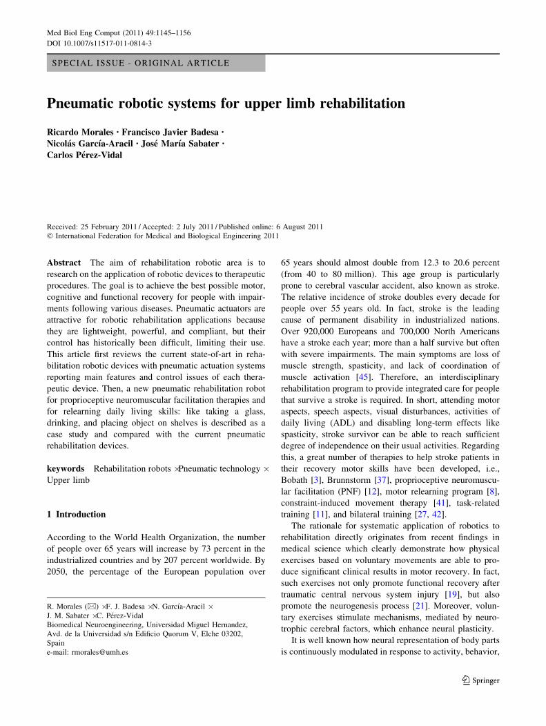
2.2 iPam
The iPam was developed by the University of Leeds [17]. It
is designed for sitting therapies and it is necessary that the
patient is fixed in the chair with a harness. This system uses
two symmetric arms with three active degrees of freedom
in each robotic arm. One of them grips the patients wrist
and the other one grips the patients arm. Also includes
three passive degrees of freedom in each grip to the patient.
This system can be used in patients with damage in both
(right/left) sides due to the symmetry of the robotic arms.
This system is linked to a user interface for the rehabili-
tation arm exercises with a 3D representation of the
patients arm and the targets to aim for. Also the interface
Fig. 1 iPam extracted from [9]
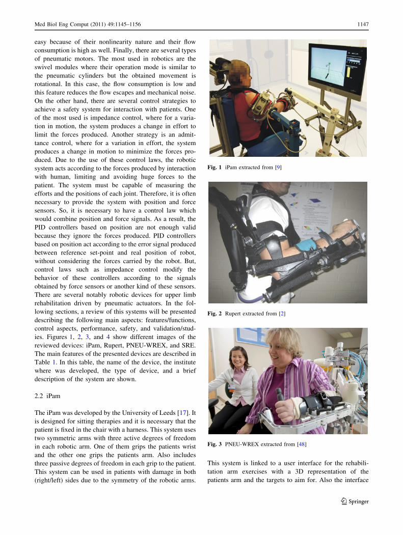
Fig. 2 Rupert extracted from [2]
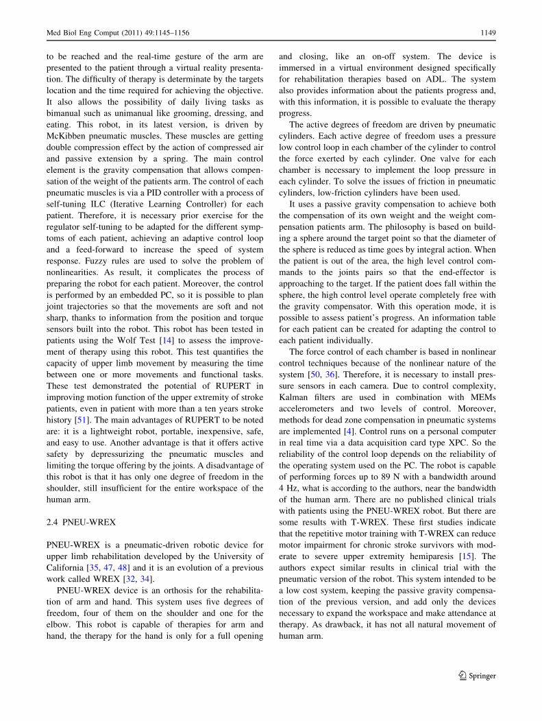
Fig. 3 PNEU-WREX extracted from [48]
Med Biol Eng Comput (2011) 49:1145–1156 1147
123

provides information about the session, like the totals of
targets and attempts. A comparison between the previous
and the current session is displayed. This robot uses low-
friction pneumatic cylinders to provide actuation at the
active revolute joints which are controlled using six pro-
portional control valves. Regarding the operation mode of
the device, highlights the gravity compensation mode
where the patient can move freely his or her arm in three
planes while the robot supports its own weight and the
patients arm weight. Moreover, the hand trajectory mode
where the robot which is attached to patients wrist, acts like
a gravity compensator and the second arm follows an
admittance control allowing patient movement through a
trajectory. The third and final mode is the joint control,
where both robot arms use an admittance control law to
ensure coordination of movements to help the patient to
perform the movement of his/her arm. Future works on this
device include impedance control of each joint in order to
control the dynamic behavior of the interaction with the
patient. A key aspect to consider in the operation of this
robot is that the position of the two robotic arms should be
restricted to the kinematics of the human arm. If the
requirements of the kinematics of human arm are not sat-
isfied, the patient may suffer serious damage [18]. For this
reason, a cooperative control for both arms has been inte-
grated. Furthermore, this robot is equipped with force
sensors to measure the effort made by the therapist and to
be replicate later during therapy. The iPam robot was
installed in the local hospital of St Mary in Leeds PCT in
the UK, within the rehabilitation unit in order to obtain
clinical results in trials with patients with disabilities. The
test demonstrated the suitability of different modes
depending on the severity of patients disabilities [16]. The
main advantages of this robot are: comfort, safety, and a
simple system to attach to human arms. Moreover, the grip
to the human arm is comfortable, safe, and easy to fix.
Although, the whole workspace of the two robotic arms
and the human arm is validated through the use of a motion
capture software and infrared cameras. The main drawback
of this iPam system is that the free space usually needed by
the therapist to assist the patient during the rehabilitation
task has not been taken into account in the design of this
rehabilitation robotic system.
2.3 RUPERT
RUPERT was developed by Arizona State University
[2, 39]. The main objective of this robot is to assist the
therapist in ADL. It can be classified as an exoskeleton
robotic device with four active and three passive degrees of
freedom. Due to exoskeleton shape, this device only allows
its use in the sitting position. The single or multiple targets
Fig. 4 SRE extracted from [7]
Table 1 Pneumatic
rehabilitation robots for upper
limbs: type and brief description
System Institute Type Brief description
iPam Univ. of Leeds UK Dual robot DoF:6 active/3 passive
2 Symmetrical robotic arms
Comfortable grip
RUPERT Arizona State Univ. Phoenix, USA Exoskeleton 4 active DoF
Wearable exoskeleton
Only for one human arm
PNEU-
WREX
Univ. of California, Irvine, USA Exoskeleton,
Orthosis
5 active DoF
Arm and hand rehabilitation.
SRE Univ. of Salford, Manchester, UK. Exoskeleton,
Orthosis
7 active DoF
Lightweight, about 2 kg
Only one grasping point
1148 Med Biol Eng Comput (2011) 49:1145–1156
123
to be reached and the real-time gesture of the arm are
presented to the patient through a virtual reality presenta-
tion. The difficulty of therapy is determinate by the targets
location and the time required for achieving the objective.
It also allows the possibility of daily living tasks as
bimanual such as unimanual like grooming, dressing, and
eating. This robot, in its latest version, is driven by
McKibben pneumatic muscles. These muscles are getting
double compression effect by the action of compressed air
and passive extension by a spring. The main control
element is the gravity compensation that allows compen-
sation of the weight of the patients arm. The control of each
pneumatic muscles is via a PID controller with a process of
self-tuning ILC (Iterative Learning Controller) for each
patient. Therefore, it is necessary prior exercise for the
regulator self-tuning to be adapted for the different symp-
toms of each patient, achieving an adaptive control loop
and a feed-forward to increase the speed of system
response. Fuzzy rules are used to solve the problem of
nonlinearities. As result, it complicates the process of
preparing the robot for each patient. Moreover, the control
is performed by an embedded PC, so it is possible to plan
joint trajectories so that the movements are soft and not
sharp, thanks to information from the position and torque
sensors built into the robot. This robot has been tested in
patients using the Wolf Test [14] to assess the improve-
ment of therapy using this robot. This test quantifies the
capacity of upper limb movement by measuring the time
between one or more movements and functional tasks.
These test demonstrated the potential of RUPERT in
improving motion function of the upper extremity of stroke
patients, even in patient with more than a ten years stroke
history [51]. The main advantages of RUPERT to be noted
are: it is a lightweight robot, portable, inexpensive, safe,
and easy to use. Another advantage is that it offers active
safety by depressurizing the pneumatic muscles and
limiting the torque offering by the joints. A disadvantage of
this robot is that it has only one degree of freedom in the
shoulder, still insufficient for the entire workspace of the
human arm.
2.4 PNEU-WREX
PNEU-WREX is a pneumatic-driven robotic device for
upper limb rehabilitation developed by the University of
California [35, 47, 48] and it is an evolution of a previous
work called WREX [32, 34].
PNEU-WREX device is an orthosis for the rehabilita-
tion of arm and hand. This system uses five degrees of
freedom, four of them on the shoulder and one for the
elbow. This robot is capable of therapies for arm and
hand, the therapy for the hand is only for a full opening
and closing, like an on-off system. The device is
immersed in a virtual environment designed specifically
for rehabilitation therapies based on ADL. The system
also provides information about the patients progress and,
with this information, it is possible to evaluate the therapy
progress.
The active degrees of freedom are driven by pneumatic
cylinders. Each active degree of freedom uses a pressure
low control loop in each chamber of the cylinder to control
the force exerted by each cylinder. One valve for each
chamber is necessary to implement the loop pressure in
each cylinder. To solve the issues of friction in pneumatic
cylinders, low-friction cylinders have been used.
It uses a passive gravity compensation to achieve both
the compensation of its own weight and the weight com-
pensation patients arm. The philosophy is based on build-
ing a sphere around the target point so that the diameter of
the sphere is reduced as time goes by integral action. When
the patient is out of the area, the high level control com-
mands to the joints pairs so that the end-effector is
approaching to the target. If the patient does fall within the
sphere, the high control level operate completely free with
the gravity compensator. With this operation mode, it is
possible to assess patient’s progress. An information table
for each patient can be created for adapting the control to
each patient individually.
The force control of each chamber is based in nonlinear
control techniques because of the nonlinear nature of the
system [50, 36]. Therefore, it is necessary to install pres-
sure sensors in each camera. Due to control complexity,
Kalman filters are used in combination with MEMs
accelerometers and two levels of control. Moreover,
methods for dead zone compensation in pneumatic systems
are implemented [4]. Control runs on a personal computer
in real time via a data acquisition card type XPC. So the
reliability of the control loop depends on the reliability of
the operating system used on the PC. The robot is capable
of performing forces up to 89 N with a bandwidth around
4 Hz, what is according to the authors, near the bandwidth
of the human arm. There are no published clinical trials
with patients using the PNEU-WREX robot. But there are
some results with T-WREX. These first studies indicate
that the repetitive motor training with T-WREX can reduce
motor impairment for chronic stroke survivors with mod-
erate to severe upper extremity hemiparesis [15]. The
authors expect similar results in clinical trial with the
pneumatic version of the robot. This system intended to be
a low cost system, keeping the passive gravity compensa-
tion of the previous version, and add only the devices
necessary to expand the workspace and make attendance at
therapy. As drawback, it has not all natural movement of
human arm.
Med Biol Eng Comput (2011) 49:1145–1156 1149
123
2.5 Salford rehabilitation exoskeleton (SRE)
The Salford rehabilitation exoskeleton (SRE) is a multi-
jointed gravity compensated upper arm assistive exoskel-
eton developed at the University of Salford [22, 23].
This device has an exoskeleton configuration with seven
degrees of freedom and three operation modes. With seven
active degrees of freedom get the 75% of the complete
movement of human arm, it is sufficient to assist in reha-
bilitation therapies of upper-limb. It is designed to work with
adult patients, and is equipped with means of adjustment for
each patient. This system has a 3D virtual environment,
specially designed for ADL, which displayed several virtual
objects on a virtual table and an avatar of the patient. The
virtual environment is complemented by a database to store
information and progress of each patient. The virtual envi-
ronment has stored primitive movements so that the therapist
determines which of them should be used on the patient.
Another possibility offered by the virtual environment is the
choice for the therapist to limit the speed of movement of the
patient, so that it can be adapted for each patient. A promi-
nent feature of the software is that it has pre-programmed
routines for warming up the patients arm thus avoiding
possible injury. Moreover, the software includes reinforce-
ments for the patient, like playing music while completing an
exercise and stop music when the exercise is over. This robot
is based on antagonist configuration of pneumatic muscles
which are placed in the base of the robot and motion carried
by wire transmission from base to each joint. The muscles in
antagonist configuration work very similar to human arm
muscles, contributing in this way, more realism and comfort
in use. The control law varies depending on the type of
operation mode, which can be positioned at each joint,
torque control at each joint or impedance control. One
operation mode is totally assisted and the robot moves
completely the patients arm. Another one is partial assis-
tance mode, where through the biofeedback read the inten-
tion of moving the patient and help partially. The third and
final operation mode, in which the patient moves freely and
the robot returns reaction forces depending on the interaction
with the virtual world. Always control of position and torque
are separated. The control loop incorporates a force/torque
sensor with six degrees of freedom in the wrist of the robot to
detect the intention of moving the patient is employed. All
control loops are integrated on a PC which is dedicated to
control and to communicate with the rehabilitation software
running on another computer.
There is no published clinical experimentation with this
device. So it is difficult to evaluate the benefit of the
therapy with the SRE robot. Although, this device can be
used as exercise facility for joints of the upper limb as well
as a rehabilitation/power assist orthosis for persons with
loss of/reduced power in the limb [43].
A deficiency expressed by the authors is that the
mechanical design has a singularity when the arm is par-
allel to the horizontal. Another drawback of the system is
that the torque exerted by the mechanism of antagonistic
pneumatic muscle depends on the position of each joint,
complicating the control loop. Another fault is that the
pneumatic muscle system causes a delay between
the desired signal and the performed signal. Although, the
delayed signal has the same form as the desired one,
therefore, not influence the therapy results.
3 Case study: pneumatic robotic device for early
delivering of rehabilitation therapy at Miguel
Hernandez University
3.1 Introduction
The design of the rehabilitation robot presented in this
section was carried out at Miguel Hernandez University
(UMH) and born from the need of automation of delivering
PNF therapies to patients with reduced mobility in supine
and sitting position. The movement patterns which will be
assisted by the robotic device are:
– D1 flexion: the D1 flexion pattern begins with the
shoulder and elbow extended at the patients side and
the wrist supinated. The terminal position for the D1
flexion pattern is the shoulder and elbow are flexed,
internally rotated, and adducted, the wrist in supination.
The patient should look as though he or she is reaching
across the body to touch the opposite anterior deltoid,
with the dorsal side of the hand.
– D1 extension: this time, the patient begins in the
terminal position of the D1 flexion pattern, with the
patient reaching across the body to touch the opposite
anterior deltoid. The D1 extension pattern is to extend
the shoulder and elbow, externally rotate the humerus,
abduct the arm, and supinate the wrist.
– D2 flexion: the D2 extension pattern begins with the
shoulder and elbow flexed and adducted, the humerus
internally rotated, and the wrist pronated. The patient
should look as though he or she is touching the axis of
the opposite hip. The movement consists of abducting
the shoulder, externally rotating the humerus, and
supinating the wrist. One may describe it as taking a
sword out of its holster and raising it up to the sky.
– D2 extension: the D2 flexion pattern is again, the
counter movement to the D2 extension pattern. The
patient starts in the terminal position of the D2
extension patter with the shoulder and elbow extended
and adducted, the humerus externally rotated, and the
wrist supinated. The movement occurs when the patient
1150 Med Biol Eng Comput (2011) 49:1145–1156
123
flexes shoulder and elbow, adducts the arm, internally
rotates the humerus, and pronates the wrist.
The physiotherapist moves the patient through the range
of motion initially, to allow the patient to understand how
the limb will be moving before adding resistance; this is the
same for all diagonal patterns. Once the patient understands
the movement, the clinician applies manual resistance to
the patient as he or she moves along the range of motion.
Simple, one word verbal cues from the clinician are
important to achieve maximal results from the patient
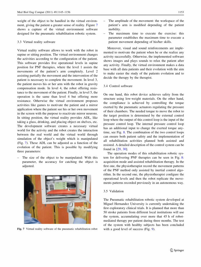
Moreover, the rehabilitation device was designed to be
used for relearning daily living skills: like take a glass,
drinking, and placing object on shelves. The virtual reality
system creates a necessary virtual world for the activity and
the robot assists the patient during the execution of a pre-
configured activity of daily living. Of course, these ADL
can be adjusted in function of the evolution of the patient.
Most of the systems designed by engineers for medical
applications lack of the involvement of final users of
the system at the beginning of the design process of the
mechatronic device. In our case, the philosophy of the
development process was to involve health care profes-
sionals and people with stroke during the development
process with the objective of maximizing the acceptation of
the system by the end-user and the physiotherapists. The
development process was similar to the one described on
[17].
3.2 System description
The designed robot solution comprises two arm robots, one
of three active degrees of freedom to control the patients’
hand and one more of three active degrees of freedom to
control the movements of the patients’ elbow. This con-
figuration tries to mimic the way that the physiotherapists
do the manual PNF movements. In a first aspect, the pro-
posed rehabilitation robot is a robotic system for control-
ling a movement of a user’s upper limb, said robotic arm
forming a kinematic chain extending from a proximal to a
distal end and comprising a grip for positioning said user’s
hand at a distal end, characterised in that the kinematic
chain possesses redundancy in a distal region, such that the
movement of the user’s hand can be decoupled from other
parts of the kinematic chain. A patient places his or her
hand in the grip provided at the distal end. In this region,
redundancy in the kinematic chain is provided, which
means that the whole kinematic chain except for the hand
grip might perform movements while the hand grip (and
thus the patient’s hand) does not move. This presents a
major improvement in comfort and safety for patients and
attending physicians. If a certain movement is to be per-
formed, the kinematic chain can normally be moved to its
appropriate position without moving the hand grip. The
patient does not need to change his position or orientation
and the robotic arm is able to perform all its movements
without hitting the patient or physician.
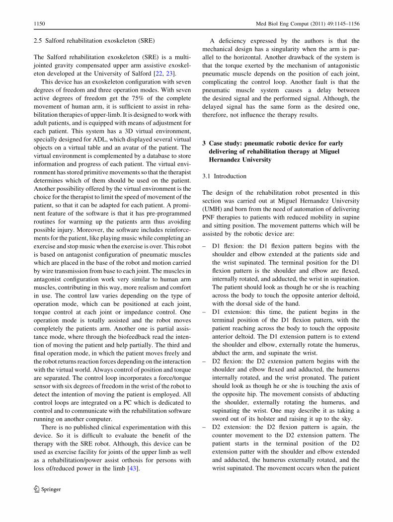
Both robotic arms are fixed to a mobile structure for
transporting the robot. In this structure, the whole elec-
tronics, electrical, and pneumatic elements necessary to
operate the robot are installed. The upper robotic arm is
configured as a scara robot in its first two joints and a
mechanical passive gravity compensator is designed for the
third joint. In the second robotic arm, the first two rota-
tional degrees of freedom drives are fixed to the structure,
providing less inertial forces. The third active joint, a
prismatic one, is actuated by a pneumatic cylinder. Both
robotic arms are shown in the Fig. 5.
From our point of view, one of the main features to take
into account in the design of rehabilitation robotics is
safety. For this reason, pneumatic actuators has been
selected. Moreover, this kind of actuators can exert enough
driving power despite being lightweight and having a small
size because the ratio of its output power to its weight is
large. In short, a pneumatic swivel module with angular
displacement encoder (DSMI manufactured by Festo) has
been used as an actuator for each joint. The semi-rotative
drives are being controlled by two proportional pressure
valves (MPPE manufactured by festo). The valve MPPE is
designed so that pressure output is proportional to voltage
input through a proportional electromagnet. In this
Fig. 5 UMH-pneumatic robotic device at clinical institution
Med Biol Eng Comput (2011) 49:1145–1156 1151
123
configuration (two proportional valves and a pneumatic
actuator), the pressure of the two chambers of the pneu-
matic drive can be regulated to get a desired output force
and to track a desired trajectory [25] (Fig. 6).
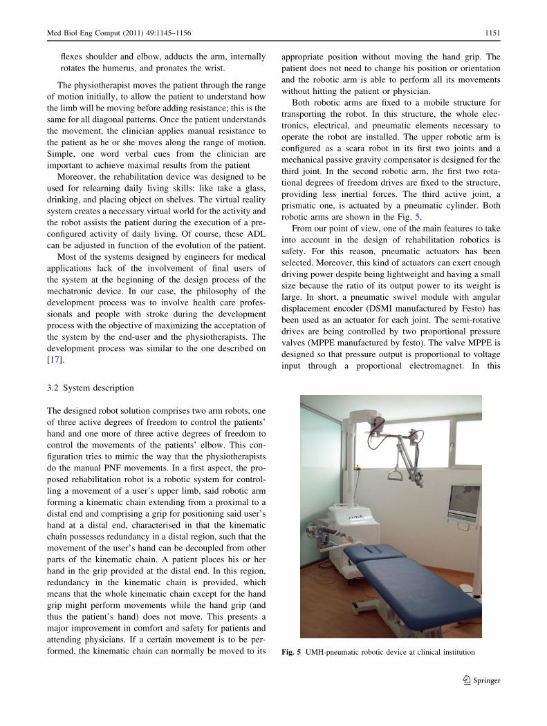
The core of the control system is a motion controller
board (DMC-40) manufactured by Galil. It operates stand-
alone or interfaces to a PC with Ethernet 10/100Base-T or
RS232. The controller includes optically isolated I/O, high-
power outputs capable of driving brakes or relays, and
analog inputs for interfacing to analog sensors. Six analog
outputs from the DMC-40 board are used to control each
pneumatic actuator through two proportional pressure
valves. An electronic board (it is called distributor) has
been designed to convert each joint’s control signal in two
voltage inputs for its respective proportional pressure
valves (It is assumed that the valves behavior is identical).
This enables the pressure difference across the pneumatic
drive to be specified by the control software changes alone
and also allows the individual chamber pressures to be
regulated by the valves themselves.
Virtual reality combined with mechatronic devices can
also improve the results of the robotic therapy. It has been
shown that patients can be more successful in their training
or their rehabilitation when incentives are used in the
training. Virtual reality can provide this kind of incentives.
For example, a patient will normally be interested in
recovering movements from everyday life such as grabbing
an object from a table. Virtual reality can provide an
environment, in which the patient may under the control of
the robotic arms grab such an object. Virtual reality can
also aid in showing that the patient is improving (since
grabbing the object is easier). A computer with a human
machine interface based on virtual reality techniques is
connected to the motion control board via ethernet link.
The virtual activities implemented on the control soft-
ware for the rehabilitation robot presented in this article
can be classified as ADL and activities for therapies based
on PNF. The activities within the PFN therapy represent an
innovation in this field. In the first phases of PNF therapy,
where the patient is fully assisted by the robot, the patient
is motivated by his or her own image (like a mirror),
through the use of an integrated webcam, to stimulate the
mirror neurons. In the phase where the robot offers resis-
tance, the software displays visual activities in coordination
with the robots movement to motivate the patient. The start
and end positions of the movement and the path of the
movement are highlights to be made by the patient. In
ADL, the patient is immersed in the virtual environment
where he or she performs activities such as taking a glass
from the table and drink or placing an object on the shelf.
To increase the degree of reality, force feedback is applied
to real world from virtual world through the robot, e.g., the
Fig. 6 Pneumatic rehabilitation robotic system: components and interfaces
1152 Med Biol Eng Comput (2011) 49:1145–1156
123
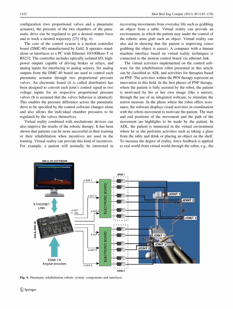
weight of the object to be handled in the virtual environ-
ment, giving the patient a greater sense of reality. Figure 7
shows a capture of the virtual environment software
designed for the pneumatic rehabilitation robotic system.
3.3 Virtual reality software
Virtual reality software allows to work with the robot in
supine or sitting position. The virtual environment changes
the activities according to the configuration of the patient.
This software provides five operational levels in supine
position for PNF therapies, where the level 1 assists the
movements of the patient’s arm completely. Level 2
assisting partially the movement and the intervention of the
patient is necessary to complete the movement. In level 3,
the patient moves his or her arm with the robot in gravity
compensation mode. In level 4, the robot offering resis-
tance to the movement of the patient. Finally, in level 5, the
operation is the same than level 4 but offering more
resistance. Otherwise the virtual environment proposes
activities like games to motivate the patient and a mirror
application where the patient see his or her own movement
in the screen with the purpose to reactivate mirror neurons.
In sitting position, the virtual reality provides ADL, like
taking a glass, drinking, and placing object on shelves, etc.
The development software creates a necessary virtual
world for the activity and the robot creates the interaction
between the real world and the virtual world through
simulation of the object’s weight which is manipulated
(Fig. 7). These ADL can be adjusted as a function of the
evolution of the patient. This is possible by modifying
three parameters:
– The size of the object to be manipulated: With this
parameter, the accuracy for catching the object is
adjusted.
– The amplitude of the movement: the workspace of the
patient’s arm is modified depending of the patient
mobility.
– The maximum time to execute the exercise: this
parameter establishes the maximum time to execute a
patient movement depending of his/her skills.
Moreover, visual and sound reinforcements are imple-
mented to motivate the patient when he or she realize any
activity successfully. Otherwise, the implemented software
shows images and plays sounds to relax the patient after
any activity. Finally, the virtual environment makes a data
base with all data patients and their evolution with the aim
to make easier the study of the patients evolution and to
decide the therapy by the therapist.
3.4 Control software
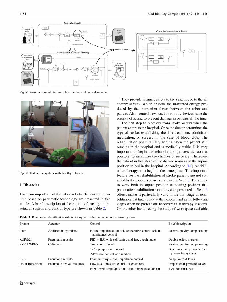
On one hand, this robot device achieves safety from the
structure using low-weight materials. On the other hand,
the compliance is achieved by controlling the torque
exerted by the pneumatic actuators regulating the pressure
of their chambers. The needed torque to move the robot to
the target position is determined by the external control
loop where the output of this control loop is the input of the
pressure control loop. The internal pressure control loop
has an additional input to change the exerted torque any-
time, see Fig. 8. The combination of the two control loops
can ensure both patient safety and the implementation of
all rehabilitation activities planned both assisted and
resisted. A detailed description of the control system can be
found in [29, 30].
The operation modes of this rehabilitation robotic sys-
tem for delivering PNF therapies can be seen in Fig. 8:
acquisition mode and assisted rehabilitation therapy. In the
first one, the physiotherapist record the movement patterns
of the PNF method only assisted by inertial control algo-
rithm. In the second one, the physiotherapist configure the
operational levels and then the robot replicate the move-
ments patterns recorded previously in an autonomous way.
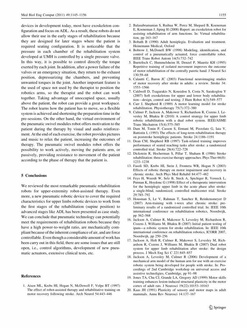
3.5 Validation
The Pneumatic rehabilitation robotic system developed at
Miguel Hernandez University is currently undertaking the
first exploratory clinical trials. It is planned that more than
50 stroke patients from different local institutions will use
the system, accumulating over more that 45 h of robot-
mediated therapy per patient during three months. The test
of the system with healthy subjects has been concluded
with a good level of success (Fig. 9).Fig. 7 Virtual reality software of the pneumatic rehabilitation robot
Med Biol Eng Comput (2011) 49:1145–1156 1153
123
4 Discussion
The main important rehabilitation robotic devices for upper
limb based on pneumatic technology are presented in this
article. A brief description of these robots focusing on the
actuator system and control type are shown in Table 2.
They provide intrinsic safety to the system due to the air
compressibility, which absorbs the unwanted energy pro-
duced by the interaction forces between the robot and
patient. Also, control laws used in robotic devices have the
priority of acting to prevent damage in patients all the time.
The first step to recovery from stroke occurs when the
patient enters to the hospital. Once the doctor determines the
type of stroke, establishing the first treatment, administer
medication, or surgery in the case of blood clots. The
rehabilitation phase usually begins when the patient still
remains in the hospital and is medically stable. It is very
important to begin the rehabilitation process as soon as
possible, to maximize the chances of recovery. Therefore,
the patient in this stage of the disease remains in the supine
position in bed in the hospital. According to [14], rehabili-
tation therapy must begin in the acute phase. This important
feature for the rehabilitation of stroke patients are not sat-
isfied by the robotics devices reviewed in Sect. 2. The ability
to work both in supine position as seating position that
pneumatic rehabilitation robotic system presented on Sect. 3
offers, makes it particularly valid in the first stage of reha-
bilitation that takes place at the hospital and in the following
stages when the patient still needed regular therapy sessions.
On the other hand, seeing the study of workspace available
Fig. 8 Pneumatic rehabilitation robot: modes and control scheme
Fig. 9 Test of the system with healthy subjects
Table 2 Pneumatic rehabilitation robots for upper limbs: actuators and control system
System Actuator Control Brief description
iPam Antifriction cylinders Future impedance control, cooperative control scheme
admittance control
Passive gravity compensating
RUPERT Pneumatic muscles PID ? ILC with self-tuning and fuzzy techniques Double effect muscles
PNEU-WREX Cylinders Two control levels
1-Torque/position control
2-Pressure control of chambers
Passive gravity compensating
Dead zone compensator for
pneumatic systems
SRE Pneumatic muscles Position, torque, and impedance control Adaptive root locus
UMH RehabRob Pneumatic swivel modules Low level: pressure control of chambers
High level: torque/position future impedance control
Proportional pressure valves
Two control levels
1154 Med Biol Eng Comput (2011) 49:1145–1156
123
devices in development today, most have exoskeleton con-
figuration and focus on ADL. As a result, these robots do not
allow their use in the early stages of rehabilitation because
they are designed for later stages where the patient is
required seating configuration. It is noticeable that the
pressure in each chamber of the rehabilitation system
developed at UMH is controlled by a single pressure valve.
In this way, it is possible to control directly the torque
exerted by each joint. In addition, after a power failure of the
valves or an emergency situation, they return to the exhaust
position, depressurizing the chambers, and preventing
unwanted torques in the joint. Another important feature is
the used of space not used by the therapist to position the
robotics arms, so the therapist and the robot can work
together. Taking advantage of unoccupied space, usually
above the patient, the robot can provide a great workspace.
The robot learns how the patient has to move, so a flexible
system is achieved and shortening the preparation time in the
pre-sessions. On the other hand, the virtual environment of
the pneumatic swivel modules robot offers motivation to the
patient during the therapy by visual and audio reinforce-
ment. At the end of each exercise, the robot provides pictures
and music to relax the patient, increasing the outcomes of
therapy. The pneumatic swivel modules robot offers the
possibility to work actively, moving the patients arm, or
passively, providing resistance to movement of the patient
according to the phase of therapy that the patient is.
5 Conclusions
We reviewed the most remarkable pneumatic rehabilitation
robots for upper-extremity robot-assisted therapy. Even
more, a new pneumatic robotic device to cover the required
characteristics for upper limbs robotic devices to work from
the first stages of the rehabilitation (supine position) to
advanced stages like ADL has been presented as case study.
We can conclude that pneumatic technology can potentially
meet the requirements of rehabilitation robots because they
have a high power-to-weight ratio, are mechanically com-
pliant because of the inherent compliance of air, and are force
controllable. Even though a considerable amount of work has
been carry out in this field, there are some issues that are still
open, i.e., control algorithms, development of new pneu-
matic actuators, extensive clinical tests, etc.
References
1. Aisen ML, Krebs HI, Hogan N, McDowell F, Volpe BT (1997)
The effect of robot-assisted therapy and rehabilitative training on
motor recovery following stroke. Arch Neurol 54:443–446
2. Balasubramanian S, Ruihua W, Perez M, Shepard B, Koeneman
E, Koeneman J, Jiping H (2008) Rupert: an exoskeleton robot for
assisting rehabilitation of arm functions. In: Virtual rehabilita-
tion, pp 163–167
3. Bobath B (1990) Adult hemiplegia. Evaluation and treatment.
Heinemann Medical, Oxford
4. Bobrow J, McDonell BW (1998) Modeling, identification, and
control of a pneumatically actuated, force controllable robot.
IEEE Trans Robot Autom 14(5):732–742
5. Buetefisch C, Hummelsheim H, Denzel P, Mauritz KH (1995)
Repetitive training of isolated movement improves the outcome
of motor rehabilitation of the centrally paretic hand. J Neurol Sci
130:59–68
6. Calautti C, Baron JC (2003) Functional neuroimaging studies
of motor recovery after stroke in adults: a review. Stroke 34:
1553–1566
7. Caldwell D, Tsagarakis N, Kousidou S, Costa N, Sarakoglou Y
(2007) Soft exoskeletons for upper and lower body rehabilita-
tion—design, control and testing. J Hum Robot 4(3):549–577
8. Carr J, Shepherd R (1989) A motor learning model for stroke
rehabilitation. Physiotherapy 75(7):372–380
9. Culmer P, Jackson A, Makower S, Richardson R, Cozens J, Le-
vesley M, Bhakta B (2010) A control strategy for upper limb
robotic rehabilitation with a dual robot system. IEEE/ASME
Trans Mechatron 15(4):575–585
10. Dam M, Tonin P, Casson S, Ermani M, Pizzolato G, Iaia V,
Battistin L (1993) The effects of long-term rehabilitation therapy
on poststroke hemiplegic patients. Stroke 24:1186–1191
11. Dean CM, Shepherd RB (1997) Task-related training improves
performance of seated reaching tasks after stroke: a randomized
controlled trial. Stroke 28(4):722–728
12. Dickstein R, Hocherman S, Pillar T, Shaham R (1986) Stroke
rehabilitation: three exercise therapy approaches. Phys Ther 66(8):
1233–1238
13. Fasoli SD, Krebs HI, Stein J, Frontera WR, Hogan N (2003)
Effects of robotic therapy on motor impairment and recovery in
chronic stroke. Arch Phys Med Rehabil 84:477–482
14. Feys H, Weerdt W, Selz B, Steck A, Spichiger R, Vereeck L,
Putman K, Hoydonc G (1998) Effect of a therapeutic intervention
for the hemiplegic upper limb in the acute phase after stroke:
a single-blind, randomized, controlled multicenter trial. Stroke
29:785–792
15. Housman S, Le V, Rahman T, Sanchez R, Reinkensmeyer D
(2007) Arm-training with t-wrex after chronic stroke: pre-
liminary results of a randomized controlled trial. In: IEEE 10th
international conference on rehabilitation robotics, Noordwijk,
pp 562–568
16. Jackson A, Culmer R, Makower S, Levesley M, Richardson R,
Cozens J, Williams M, Bhakta B (2007) Initial patient testing of
ipam—a robotic system for stroke rehabilitation. In: IEEE 10th
international conference on rehabilitation robotics, ICORR 2007,
Noordwijk, pp 250–256
17. Jackson A, Holt R, Culmer R, Makower S, Levesley M, Rich-
ardson R, Cozens J, Williams M, Bhakta B (2007) Dual robot
system for upper limb rehabilitation after stroke: the design
process. J Mech Eng Sci C 221:845–857
18. Jackson A, Levesley M, Culmer R (2006) Development of a
mechanical arm model of the human arm for use with an exercise
robotic system being developed for people with stroke. In: Pro-
ceedings of 2nd Cambridge workshop on universal access and
assistive technoligies, Cambridge, pp 91–98
19. Jones TA, Chu CJ, Grande LA, Gregory AD (1999) Motor skills
training enhances lesion-induced structural plasticity in the motor
cortex of adult rats. J Neurosci 19(22):10153–10163
20. Kaas JH (1991) Plasticity of sensory and motor maps in adult
mammals. Annu Rev Neurosci 14:137–167
Med Biol Eng Comput (2011) 49:1145–1156 1155
123

21. Kempermann G, Praag HV, Gage F (2000) Activity-dependent
regulation of neuronal plasticity and self repair. Prog Brain Res
127:35–48
22. Kousidou S, Tsagarakis N, Caldwell D, Smith C (2006) Assistive
exoskeleton for task based physiotherapy in 3-dimensional space. In:
The first IEEE/RAS-EMBS international conference on biomedical
robotics and biomechatronics, BioRob 2006, Pisa, pp 266–271
23. Kousidou S, Tsagarakis N, Smith C, Caldwell D (2007) Task
orientated biofeedback system for the rehabilitation of the upper
limb. In: IEEE 10th international conference on rehabilitation
robotics, ICORR 2007, Noordwijk, pp 376–384
24. Krebs HI, Hogan N, Aisen ML, Volpe BT (1998) Robot-aided
neurorihabilitation. IEEE Trans Rehabil Eng 6:75–87
25. Lu B, Tao G, Xiang Z, Zhong W (2008) Modeling and control of
the pneumatic modeling and control of the pneumatic constant
pressure system for zero gravity simulation. In: IEEE ASME
international conference on advanced intelligent mechatronics,
AIM 2008, Xian, pp 688–693
26. Lum PS, Burgar CG, Shor PC, Majmundar M, der Loos MV
(2002) Robot-assisted movement training compared with con-
ventional therapy techniques for the rehabilitation of upper-limb
motor function after stroke. Arch Phys Med Rehabil 83:952–959
27. Matyas T, Mudie M (2000) Can simultaneous bilateral movement
involve the undamaged hemisphere in reconstruction of neural
networks damaged by stroke. J Disabil Rehabil 22(1/2):23–37
28. Miller EL, Murray L, Richards L, Zorowitz RD, Bakas T, Clark
P, Billinger SA, American Heart Association Council on Car-
diovascular Nursing, the Stroke Council (2010) Comprehensive
overview of nursing and interdisciplinary rehabilitation care of
the stroke patient: a scientific statement from the American Heart
Association. Stroke 41(10):2402–2448
29. Morales R, Badesa FJ, Domenech LM, Garcıa N, Sabater JM,
Menchon M, Fernandez E (2010) Design and control of a reha-
bilitation robot driven by pneumatic swivel modules. In: IEEE
(ed) 3rd IEEE RAS/EMBS internacional conference on bio-
medical robotics and biomechatronics, Tokyo, pp 566 –571
30. Morales R, Badesa FJ, Domenech LM, Garcıa N, Sabater JM, Perez
C, Fernandez E, Menchon M (2010) Pneumatic rehabilitation
robot: modelling and control. In: Proceedings for the joint con-
ference of ISR 2010 (41st international symposium on robotics)
and ROBOTIK 2010 (6th German conference on robotics),
Munich, pp 379–386
31. Nudo RJ, Friel KM (1999) Cortical plasticity after stroke:
implications for rehabilitation. Rev Neurol 155:713–717
32. Rahman T, Sample W, Seliktar R (2004) Design and testing of
wrex. In: Bien ZZ, Stefanov D (eds) Advances in rehabilitation
robotics, vol 306. Springer, Berlin / Heidelberg, pp 243–250
33. Rossini P, Pauri F (2000) Neuromagnetic integrated methods
tracking human brain mechanism of sensorimotor areas ‘‘plastic’’
reorganization. Brain Res 33:131–154
34. Sanchez R, Reinkensmeyer D, Shah J, Liu P, Rao S, Smith R,
Cramer S, Rahman T, Bobrow J (2004) Monitoring functional
arm movement for home-based therapy after stroke, vol 2. In:
26th annual international conference of the IEEE, engineering in
medicine and biology society, IEMBS ’04, San Francisco,
pp 4787–4790
35. Sanchez R, Wolbrecht E, Smith R, Liu J, Rao S, Cramer S,
Rahman T, Bobrow J, Reinkensmeyer D (2005) A pneumatic
robot for re-training arm movement after stroke: rationale and
mechanical design. In: Proceedings of the 9th international con-
ference on rehabilitation robotics. Omnipress, Chicago/Madison,
pp 500–504
36. Sanville F (1971) A new method of specifying the flow capacity
of pneumatic fluid power valves. Hydraul Pneum Power 17:195
37. Sawner K, Lavigne J (1992) Brunnstrom’s movement therapy in
hemiplegia: a neurophysiological approach, 2 edn. Lippincott
Williams and Wilkins, Philadelphia
38. Staines WR, McIlroy WE, Graham SJ, Black SE (2001) Bilateral
movement enhances ipsilesional cortical activity in acute stroke:
a pilot functional MRI study. Neurology 51:401–404
39. Sugar T, He J, Koeneman E, Koeneman J, Herman R, Huang H,
Schultz R, Herring D, Wanberg J, Balasubramanian S, Swenson
P, Ward J (2007) Design and control of rupert: a device for
robotic upper extremity repetitive therapy. IEEE Trans Neural
Syst Rehabil Eng 15:336–346
40. Taub E, Miller NE, Novack TA, Cook EW, Fleming WC, Nep-
omuceno CS, Connell JS, Crago JE (1993) Technique to improve
chronic motor deficit after stroke. Arch Phys Med Rehabil 74:
347–354
41. Taub E, Uswatte G (2006) Constraint-induced movement ther-
apy: answers and questions after two decades of research. Neu-
roRehabilitation 21(2):93–95
42. Tijs E, Matyas T (2007) Bilateral training does not facilitate
performance of copying tasks in poststroke hemiplegia. Neuro-
rehabil Neural Repair 20(4):473
43. Tsagarakis N, Kousidou S, Caldwell D (2008) Case study: soft-
actuated exoskeleton for the use in physiotherapy and training. In:
Pons JL (ed) Wearable robots: biomechatronic exoskeletons.
Wiley, Chichester, pp 269–278
44. van der Lee JH, Wagenaar RC, Lankhorst GJ, Vogelaar TW,
Deville WL, Bouter LM (1999) Forced use of the upper extremity
in chronic stroke patients: results from a single-blind randomized
clinical trial. Stroke 30:2369–2375
45. van Peppen R, Kwakkel G, van der Wel BH, Kollen B, Hobbelen
J, Buurke J, Halfens J, Wagenborg L, Vogel M, Berns M, van
Klaveren R, Hendriks H, Dekker J (2004) KNGF clinical practice
guideline for physical therapy in patients with stroke. review of
the evidence. Nederlands Tijdschrift voor Fysiotherapie 114(5)
46. Volpe BT, Krebs HI, Hogan N, Edelstein L, Diels C, Aisen ML
(1999) Robot training enhanced motor outcome in patients with
stroke maintained over three years. Neurology 53:1874–1876
47. Wolbrecht E, Leavitt J, Reinkensmeyer D, Bobrow J (2006) Con-
trol of a pneumatic orthosis for upper extremity stroke rehabilita-
tion. In: 28th annual international conference of the IEEE in
engineering in medicine and biology society, EMBS ’06, New
York
48. Wolbrecht E, Reinkensmeyer D, Bobrow E (2010) Pneumatic
control of robots for rehabilitation. Int J Robot Res 29:23–38
49. Wolf S (1983) Electromyographic biofeedback applications to
stroke patients: a critical review. Phys Ther 63:1448–1459
50. Xiang F, Wikander J (2002) Block-oriented approximate feed-
back linearization for control of pneumatic actuator system.
Control Eng Pract 12:387–399
51. Zang H, Balasubramanian S, Ruihua W, Austin H, Buchanan S,
Herman R, Jiping H (2010) Rupert closed loop control design. In:
2010 annual international conference of the IEEE engineering in
medicine and biology society (EMBC), Buenos Aires, pp 3686–3689
1156 Med Biol Eng Comput (2011) 49:1145–1156
123