Parallel Robotic Manipulation via Pneumatic Artificial Muscles
8
Parallel Robotic Manipulation via Pneumatic Artificial Muscles Dimitris Gryparis, George Andrikopoulos and Stamatis Manesis Department of Electrical and Computer Engineering, University of patras, Eratosthenous str., Rio, Greece Keywords: Pneumatic Artificial Muscles, Parallel Manipulator, PID Control. Abstract: In this article, a 6 Degree-of-Freedom (DOF) parallel manipulator, actuated by Pneumatic Artificial Muscles (PAMs), is being presented. Incorporated in a two Stewart Platform-based design, the novel manipulator’s motion capabilities are being examined through kinematic analysis, while the open-loop operation characteristics and performance of the manipulator’s control via a multiple PID-based scheme are being experimentally evaluated. 1 INTRODUCTION Over the last decade, there has been an increasing scientific interest in robotic manipulators that are lightweight, safe and compliant (Calabria et al., 2012; Radojicic & Surdilovic, 2009; Denkena et al., 2008). In such cases, the selection of the type of actuation that will power the manipulator is of utmost importance. The Pneumatic Artificial Muscle (PAM) has drawn the attention of the scientific community regarding its merits for utilization in biorobotic, medical and industrial applications (Andrikopoulos, Nikolakopoulos & Manesis, 2011). By mimicking the operation and properties of the organic muscle, the PAM provides a suitable solution for safer user interaction, as well as more strong and natural motion through inherent compliance, absence of mechanical parts, as well as an impressive power-to-mass ratio. The most utilized PAM-type is the McKibben Artificial Muscle which was invented by the physician Joseph L. Mckibben in the 1950s and was incorporated in artificial limps (Stewart, 1965). So far, similar PAM-actuated manipulator approaches have included one Degree-of-Freedom (DOF) per platform concepts (Calabria et al., 2012), Stewart-based platforms via the utilization of 3 PAMs conically incorporated (Radojicic & Surdilovic, 2009) and via more complex pneumatic actuation mechanics (Denkena et al., 2008). Parallel manipulator aproaches with the utilization of other actuation means have included 3- DOF parallel manipulators actuated by servomotors (Cazalilla et al., 2014), (Khosravi et al., 2014), (Ning et al., 2006) and 6-DOF Stewart-based platforms actuated via hydraulic actuators placed at the base of the robots (Guo, et al., 2007), (Pi et al., 2010). This article presents the development and control of a parallel manipulator with 6 DOFs, which was implemented in a two Stewart Platform-based design. In this novel approach, each platform consists of four PAM actuators in parallel configuration, which are being operated as antagonistic pairs, while a pneumatic cylinder is being incorporated in the center of each platform, thus, achieving 3 DOFs per moving platform. The presented manipulator possesses the advantage of incorporating more DOFs than the manipulators found in related literature, thus possessing enhanced motion capabilities, improved motion range and increased relative workspace. In addition, the cascaded configuration of the two platforms is enhanced by the placement of all the PAMs on the lower segment of the manipulator in order to provide a novel mechanical approach on the actuated motion of this parallel robotic structure. The PAM-actuated manipulator is being depicted in Figure 1. In the following sections, the experimental setup components and the kinematic analysis of the manipulator’s structure are being presented, followed by a presentation of the open-loop operation characteristics of the manipulator. Finally, the performance of the setup’s control via a multiple PID-based scheme is being experimentally evaluated. 29 Gryparis D., Andrikopoulos G. and Manesis S.. Parallel Robotic Manipulation via Pneumatic Artificial Muscles. DOI: 10.5220/0005008700290036 In Proceedings of the 11th International Conference on Informatics in Control, Automation and Robotics (ICINCO-2014), pages 29-36 ISBN: 978-989-758-040-6 Copyright c 2014 SCITEPRESS (Science and Technology Publications, Lda.)
-
Upload
khangminh22 -
Category
Documents
-
view
2 -
download
0
Transcript of Parallel Robotic Manipulation via Pneumatic Artificial Muscles
Parallel Robotic Manipulation via Pneumatic Artificial Muscles
Dimitris Gryparis, George Andrikopoulos and Stamatis Manesis Department of Electrical and Computer Engineering, University of patras, Eratosthenous str., Rio, Greece
Keywords: Pneumatic Artificial Muscles, Parallel Manipulator, PID Control.
Abstract: In this article, a 6 Degree-of-Freedom (DOF) parallel manipulator, actuated by Pneumatic Artificial Muscles (PAMs), is being presented. Incorporated in a two Stewart Platform-based design, the novel manipulator’s motion capabilities are being examined through kinematic analysis, while the open-loop operation characteristics and performance of the manipulator’s control via a multiple PID-based scheme are being experimentally evaluated.
1 INTRODUCTION
Over the last decade, there has been an increasing scientific interest in robotic manipulators that are lightweight, safe and compliant (Calabria et al., 2012; Radojicic & Surdilovic, 2009; Denkena et al., 2008). In such cases, the selection of the type of actuation that will power the manipulator is of utmost importance. The Pneumatic Artificial Muscle (PAM) has drawn the attention of the scientific community regarding its merits for utilization in biorobotic, medical and industrial applications (Andrikopoulos, Nikolakopoulos & Manesis, 2011). By mimicking the operation and properties of the organic muscle, the PAM provides a suitable solution for safer user interaction, as well as more strong and natural motion through inherent compliance, absence of mechanical parts, as well as an impressive power-to-mass ratio. The most utilized PAM-type is the McKibben Artificial Muscle which was invented by the physician Joseph L. Mckibben in the 1950s and was incorporated in artificial limps (Stewart, 1965).
So far, similar PAM-actuated manipulator approaches have included one Degree-of-Freedom (DOF) per platform concepts (Calabria et al., 2012), Stewart-based platforms via the utilization of 3 PAMs conically incorporated (Radojicic & Surdilovic, 2009) and via more complex pneumatic actuation mechanics (Denkena et al., 2008).
Parallel manipulator aproaches with the utilization of other actuation means have included 3-DOF parallel manipulators actuated by servomotors (Cazalilla et al., 2014), (Khosravi et al., 2014),
(Ning et al., 2006) and 6-DOF Stewart-based platforms actuated via hydraulic actuators placed at the base of the robots (Guo, et al., 2007), (Pi et al., 2010).
This article presents the development and control of a parallel manipulator with 6 DOFs, which was implemented in a two Stewart Platform-based design. In this novel approach, each platform consists of four PAM actuators in parallel configuration, which are being operated as antagonistic pairs, while a pneumatic cylinder is being incorporated in the center of each platform, thus, achieving 3 DOFs per moving platform.
The presented manipulator possesses the advantage of incorporating more DOFs than the manipulators found in related literature, thus possessing enhanced motion capabilities, improved motion range and increased relative workspace. In addition, the cascaded configuration of the two platforms is enhanced by the placement of all the PAMs on the lower segment of the manipulator in order to provide a novel mechanical approach on the actuated motion of this parallel robotic structure. The PAM-actuated manipulator is being depicted in Figure 1.
In the following sections, the experimental setup components and the kinematic analysis of the manipulator’s structure are being presented, followed by a presentation of the open-loop operation characteristics of the manipulator. Finally, the performance of the setup’s control via a multiple PID-based scheme is being experimentally evaluated.
29Gryparis D., Andrikopoulos G. and Manesis S..Parallel Robotic Manipulation via Pneumatic Artificial Muscles.DOI: 10.5220/0005008700290036In Proceedings of the 11th International Conference on Informatics in Control, Automation and Robotics (ICINCO-2014), pages 29-36ISBN: 978-989-758-040-6Copyright c 2014 SCITEPRESS (Science and Technology Publications, Lda.)

2 EXPERIMENTAL SETUP COMPONENTS AND KINEMATIC ANALYSIS
2.1 Setup Components
Figure 1: The parallel robotic manipulator.
The structure utilizes eight PAMs that have been incorporated on the lower segment of the manipulator. Four PAMs are utilized for the actuation of the lower platform, which are placed closer to the center of the ground plate and are characterized by 170 mm nominal length and 20mm inner diameter. Additional four PAMs are being utilized for the actuation of the upper platform, which are placed in the outer formation of the ground plate and are characterized by 220 mm nominal length and 20mm inner diameter. These PAMs are being connected to the upper platform via Teflon flexible shafts. All utilized PAMs are manufactured by Festo AG & Co. KG and feature a maximum pulling force of approximately 2000 N and a weight of less than 300 g.
In order to augment the rigidity of the construction and increase the DOF motion capabilities, two non-revolute pneumatic cylinders were placed in the center of each platform. The operational range of each cylinder is 0-6 bar and their nominal length is 300 mm. The non-rotating pistons are connected to the platforms via universal (cardan) joints. These joints allow rotations only around x or y axis.
Twelve Festo proportional pressure regulators are being utilized in order to provide compressed air to each muscle and to each pneumatic cylinder independently. In addition, two dual axis inclinometers manufactured by Level Developments Ltd were utilized featuring an effective angle measurement range of in both x and y axis, in order to provide the necessary angle feedback for the control loop that is being described in the sequel. Furthermore, two input/output cards manufactured by Measurement & Computing are being utilized for the interconnection of the pressure regulator and sensor equipment with the personal computer. The interface between the setup and the computer system components is being composed via LabVIEW software.
2.2 Forward Kinematic Analysis
A simplified axial representation of the manipulator is being presented in Figure 2. It must be noted that due to the design concept of placing all PAMs at the ground plate, the upper platform is being rotated by 45o with respect to the z axis of the lower platform in order to achieve ameliorated performance and more compact design implementation.
Figure 2: Simplified axial representation of the manipulator.
2nd metallicplate
Flexible shafts
PAMs
1st metallic plate
Immobile ground plate
Proportional Regulators
PneumaticCylinder
ICINCO�2014�-�11th�International�Conference�on�Informatics�in�Control,�Automation�and�Robotics
30

The symmetrical design concept of the manipulator and the utilization of universal joints, which allow independent movements in relation to the x-y axes, provide the advantage of considering the PAM-induced motion in each plane for the both platforms as decoupled, thus simplifying the kinematic analysis of each platform. In this way, it is possible to study the forward kinematics of each plane independently without introducing complexities due to motion coupling. The following kinematics analysis is based on a geometric analysis, as is commonly practiced in parallel robotic theory. The symbolic representation A(i,j) indicates the point where the i-th PAM (i ∈{1,…4}) is attached to the j-th link (j ∈{1,2}) in the first. The immobile ground plate denoted as 0, the middle plate as 1 and the upper plate as 2, yields the kinematic analysis of a single antagonistic segment presented in Figures 3 and 4. The symbolic representations Oq, q ∈ {0,1,2}
and '
wO , w ∈ {1,2} indicate the geometric center of
the q-th metallic platform and the w-th universal joint’s geometric center respectively.
Figure 3: Geometrical analysis of a single antagonistic pair of PAMs in the y-z plane of the lower platform.
Figure 4: Geometrical analysis of a single antagonistic pair of PAMs in the x-z plane of the lower platform.
To simplify the analysis of the manipulator, the lengths of the pneumatic cylinders are being considered as constants and are noted as l1 and l2 respectively. Furthermore, the angle in x and y axis are being denoted as i and ,i respectively, where i
indicates the lower (i=1) or the upper (i=2) platform. To further simplify the mathematical analysis,
the following notations are being utilized:
'0 1 1O O l & '
1 2 2| |O O l (1)
1 11 1O A c & '
1 1 2| O |O c (2)
2 12 3| |O A c (3)
In addition, constraints posed by the structural properties of the design ensure that:
'1 1| |O O = '
2 2| |O O =c2 (4)
2.2.1 Kinematic Analysis of the Lower Platform
The methodology used to obtain the coordinates of the endpoints of the manipulator’s platforms’ is being presented below in the following equations. The coordinates of the middle point of the straight-line segment, which is being formulated from the aforementioned endpoints, are the coordinates of the platforms’ centers. The coordinates of the points
'1O and O1 are geometrically derived from Figure 3.
'
1 1(0,0, )lO (5a)
1 2 1 1 2 1(0, sin( ), cos( ))c l cO (5b)
There is only one unique straight line that passes from both '
1O and 1O in the y-z plain in the form of
1 1z k y b where k1 is the slope of the line and b1
is a static constant. The straight line that intersects '
1O is being described by:
1 1tan( )z y l (6)
The straight line that intersects the points '
11A and 1O , and by design is vertical to (6) is
being presented below:
1 2 1 1z tan( ) cos( )y c l (7)
The following y-plane coordinate equations are being geometrically deduced via Figure 3 as:
(1,1) 2 1 1 1sin( ) c cos( )Ay c (8a)
(2,1) 2 1 1 1sin( ) c cos( )Ay c (8b)
Parallel�Robotic�Manipulation�via�Pneumatic�Artificial�Muscles
31
and substitution of (8a) and (8b) in (7) give the z-plane geometrical equations:
(1,1) 2 1 1 1 1cos( ) sin( )Az c c l (9a)
(2,1) 2 1 1 1 1cos( ) sin( )Az c c l (9b)
From Figure 4, the coordinates of O1 can be derived as:
1 2 1 2 1 1(c sin( ),0,c cos( ) )x xO l (10)
There is only a unique defined straight line that passes from both '
1O and '1O in the x-z plane, the
form of which is 2 3z k x b where k2 stands for
the line’s slope and b3 for the constant coefficient:
1 1tan( )z x l (11)
The straight line that intersects both 1O and 31A is
perpendicular to (11) based on the manipulator’s design properties, thus giving:
1 1 2 1z tan( ) cos( )x l c (12)
The following x-plane coordinate equations are being geometrically deduced via Figure 4 as:
(3,1) 2 1 1 1sin( ) cos( )Ax c c (13a)
(4,1) 2 1 1 1cos( ) c cos( )Ax c (13b)
Substitution of (13a) and (13b) in (12) gives:
2 1 1(3,1) 1 1cos( ) sin( ) lAz c c (14a)
2 1 1(4,1) 1 1cos( ) sin( ) lAz c c (14b)
Thus, Equations (8), (9), (13) and (14) can be utilized in order to compute the first platform’s center Ο1 coordinates (x,y,z) via the following geometrical representation:
1 (3,1) (4,1) 4x A AO x x (15a)
1 (1,1) (2,1) 4y A AO y y (15b)
1 (1,1) (2,1) (3,1) (4,1) 4z A A A AO z z z z (15c)
2.2.2 Kinematic Analysis of the Upper Platform
Utilization of the exact same methodology and by introducing the coordinates of the point 1O as the
new starter point, the coordinates of '2O are being
deduced in order to compute later the coordinates of O2:
'2 1 2 2sin( )( ) 2xO l c (16a)
'2 1 2 2sin( )( ) 2yO l c
(16b)
'2 (1,2) (2,2) (3,2) (4,2) 4z B B B BO z z z z
(16c)
where ( , )B i jz are auxiliary points in the three
dimensional space utilized in order to simplify the geometrical analysis and their coordinates are being derived as:
(1,2) 1 2 2 1 1 1cos( )( ) c sin( )Bz l c l (17a)
(2,2) 1 2 2 1 1 1cos( )(c ) sin( )Bz l c l (17b)
(3,2) 1 2 2 1 1 1cos( )( ) sin( )Bz c l c l (17c)
(4,2) 1 2 2 1 1 1cos( )( ) c sin( )Bz l c l (17d)
Following the previous methodology and by rotating the computed coordinates by 45o with respect to the z axis, posed by the manipulator’s upper platform design, the coordinate equations of the upper platform’s respective geometrical points are being computed as:
'
(1,2) 2 2 2 3 2
'
(1,2) 2 2 2 3 2
'
(1,2) 2 2 2 3 2
2sin( ) c cos( )
2
2sin( ) c cos( )
2
sin( ) c cos( )
A y
A y
A z
x O c
y O c
z O c
(18a)
'
(2,2) 2 2 2 3 2
'
(2,2) 2 2 2 3 2
'
(2,2) 2 2 3 2 2
2sin( ) c cos( )
2
2sin( ) c cos( )
2
cos sin
A y
A y
A z
x O c
y O c
z c c O
(18b)
'
(3,2) 2 2 2 3 2
'
(3,2) 2 2 2 3 2
'
(3,2) 2 2 2 3 2
2sin cos
2
2sin cos
2
cos sin
A x
A x
A z
x O c c
y O c c
z O c c
(18c)
'
( 4,2) 2 2 2 3 2
'
(4,2) 2 2 2 3 2
'
(4,2) 2 2 2 3 2
2sin cos
2
2sin cos
2
cos sin
A x
A x
A z
x O c c
y O c c
z O c c
(18d)
Thus, the coordinates of the endpoint O2 of the manipulator are being computed as presented below:
ICINCO�2014�-�11th�International�Conference�on�Informatics�in�Control,�Automation�and�Robotics
32
2 (1,2) (2,2) (3,2) (4,2)
2 (1,2) (2,2) (3,2) (4,2)
2 (1,2) (2,2) (3,2) (4,2)
4
4
4
x A A A A
y A A A A
z A A A A
O x x x x
O y y y y
O z z z z
(19)
3 ANTAGONISTIC OPERATION PROPERTIES AND CONTROL ALGORITHM FORMULATION
3.1 Antagonistic Open-Loop Operation of PAM Pairs
The law that governs the antagonistic motion of the PAM pairs i=1,2 and i=3,4 of the j-th platform link in the presented manipulator applies an initial state of pressure P0,j in the PAMs of the j-th link, which is increased by a quantity ΔP in those specified by i=1,3 and is decreased by the same quantity in the their antagonistic ones specified by i=2,4. The aforementioned antagonistic law is being presented below:
, 0, ( 1)wi j j kP P P (20)
where k indicates the pair of PAMs and is being defined as:
1, for 1,2 and 1
2, for 3, 4 and 1
3, for 1,2 and 2
4, for 3, 4 and 2
i j
i jk
i j
i j
and w=i+1. In this way, all spectrum of the operating
pressure range is being exploited and this law is expected to give the maximum motion range, but, due to the nonlinearities and intense hysteresis phenomena during the inflation and deflation states of the PAMs, it fails provide a smooth antagonistic operation. The symmetric around P0,j nature of the pressure spectrum, which is posed by (20), does not lead to symmetrical length alterations due to the highly nonlinear relationship describing PAM’s length with relation to the operating pressure.
In order to achieve a smoother antagonistic behavior and to avoid the various phenomena that are caused by the nonlinearities and hysteretic behavior of the PAMs a modified antagonistic law is being utilized with the appropriate insertion of corrective coefficients as shown below:
, 0,,
( 1)w ki j j
i j
PP P
C
(21)
With the experimentally derived corrective terms Ci,j regarding the i-th PAM attached to the j-th platform link, it is made possible to compensate for the PAM’s nonlinearities and improve the overall antagonistic cooperation between PAMs. The utilized PAMs operate in a range of 0-6 bar of pressure and the experimental values of the coefficients are being derived for initial pressure state P0,j=3 bar in all the PAMs. The coefficient values are being displayed in Table 1.
Table 1: Corrective coefficients.
i j
ΔP[bar]
1 1.5 2 2.5 3
Ci,j
1
1
1 1.2 1.92 2 2.1
2 1.04 1.12 1.39 1.69 1.8
3 1.28 1.48 1.92 2.13 2.31
4 1 1.23 1.49 1.68 1.91
1
2
1 1.05 1.15 1.64 2.05
2 1.09 1.22 1.7 2.09 2.25
3 1.2 1.43 1.21 2.12 2.41
4 1.12 1.21 1.48 1.69 2
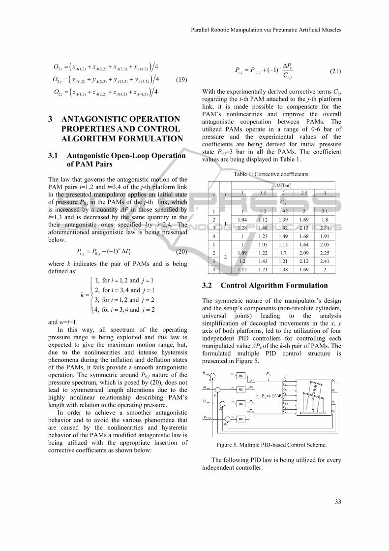
3.2 Control Algorithm Formulation
The symmetric nature of the manipulator’s design and the setup’s components (non-revolute cylinders, universal joints) leading to the analysis simplification of decoupled movements in the x, y axis of both platforms, led to the utilization of four independent PID controllers for controlling each manipulated value ΔPk of the k-th pair of PAMs. The formulated multiple PID control structure is presented in Figure 5.
Figure 5. Multiple PID-based Control Scheme.
The following PID law is being utilized for every independent controller:
Parallel�Robotic�Manipulation�via�Pneumatic�Artificial�Muscles
33

, , D,
0
( ) ( ) ( ) ( )t
k P k k I k k k k
dP t K e t K e d K e t
dx (22)
where ek(t) stands for the error signal imposed by the k-th pair of PAMs and is being formulated by subtracting the angle values θj, φj that are being measured by the inclinometers from the reference values θj,ref, φj,ref that are being provided by the user, respectively.
As presented in Figure 5 the closed loop control is being performed via four independent PID controllers, each for every PAM antagonistic pair. Every PID receives as input the respective error signal and the control effort produced is utilized as the pressure quantity ΔPk regarding the k-th PAM pair. Finally, the antagonistic law (20) is being computed and the antagonistic pressure signals are being supplied into the PAM-actuated manipulator system. The control structure’s goal is to bring the manipulator to the reference pose governed by the set-point platform angles.
4 SIMULATED PROPERTIES AND EXPERIMENTAL RESULTS
4.1 Open-Loop Performance Characteristics
In the open-loop operation of the manipulator, the user can choose moving each platform independently or both platforms combined as it is being depicted in Figure 6. The initial height of the manipulator can be adjusted by the proper selection of the initial pressure feeds of the cylinders Pj,cyl and the respective initial pressure states P0,j of the utilized PAMs.
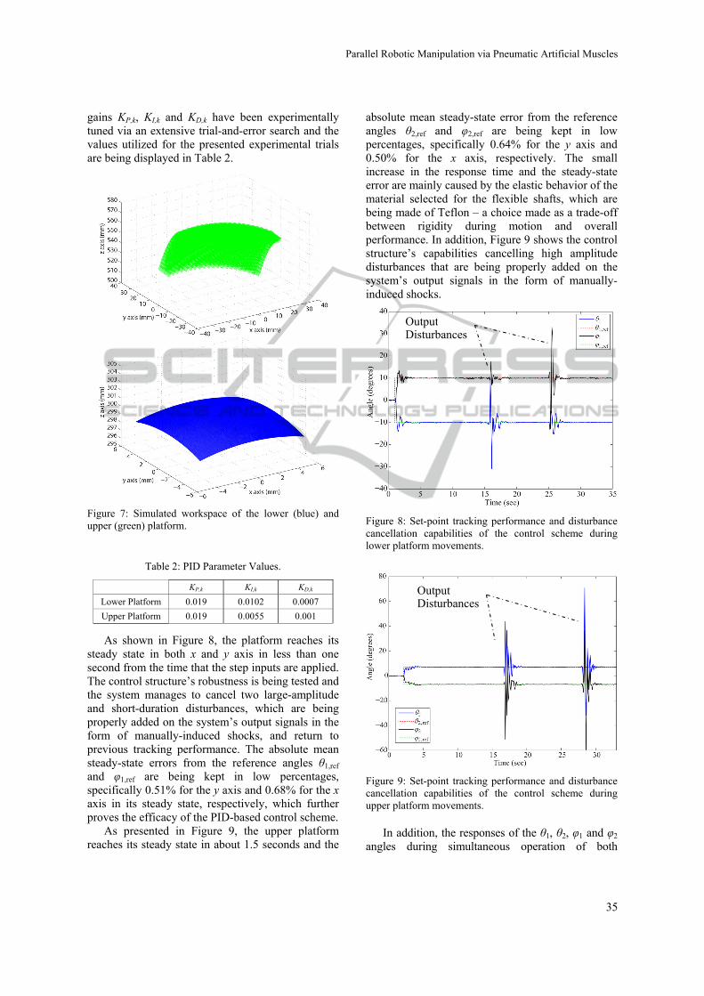
Forward kinematic analysis of the platform’s movement has been simulated in order to produce the theoretically derived workspace of the manipulator for initial PAM lengths lPAM,(j=1)=15 cm and lPAM,(j=2)=18.5 cm initial cylinder lengths lCYL,j=27 cm, which correspond to P0,j=3 bar initial PAM pressures and PCYL,j=1.5 bar initial cylinder pressures, respectively, It has to be noted that throughout the simulation trials the length of the cylinders remained unaltered, blocking any movements in the zj axes, an approach that has been also followed in the following experimental trials.
The simulated workspace of the central point of the lower platform, as computed from (15a)-(15c), whereas the simulated workspace of the upper
platform’s central point is being derived by utilizing the same methodology presented in (19). The total workspace, featuring the upper and lower platforms’ workspace in green and blue color respectively, is being displayed in Figure 7.
(a) (b) (c)
Figure 6: The robotic manipulator during (a) movement of the lower platform, (b) movement of the upper platform and (c) movement of both platforms.
The simulated workspace of the central point of the lower platform, as computed from (15a)-(15c), whereas the simulated workspace of the upper platform’s central point is being derived by utilizing the same methodology presented in (19). The total workspace, featuring the upper and lower platforms’ workspace in green and blue color respectively, is being displayed in Figure 7.
4.2 Closed-Loop Performance Results
In this Subsection the performance of the multiple PID-based scheme in controlling the manipulator setup is being evaluated. All experimental results presented have been performed with initial PAM lengths lPAM,(j=1)=15 cm and lPAM,(j=2)=18.5 cm and initial cylinder lengths lCYL,j=27 cm, which correspond to P0,j=3 bar initial PAM pressures and PCYL,j=1.5 bar initial cylinder pressures, respectively. Throughout the experimental trials the length of the cylinders remained unaltered, blocking any movements in the zj axes. With the aforementioned initial values, the platform achieves a range of motion from -15.5o to +15.5o in both x and y axes of the lower platform and from -9 to +9 degrees for the upper platform.
The responses of (θ1, φ1) of the lower platform and (θ2, φ2) of the upper platform during a set-point experiment, as well as the disturbance rejection capabilities of the control scheme are being displayed in Figures 8 and 9, respectively. The PID
ICINCO�2014�-�11th�International�Conference�on�Informatics�in�Control,�Automation�and�Robotics
34
gains KP,k, KI,k and KD,k have been experimentally tuned via an extensive trial-and-error search and the values utilized for the presented experimental trials are being displayed in Table 2.
Figure 7: Simulated workspace of the lower (blue) and upper (green) platform.
Table 2: PID Parameter Values.
KP,k KI,k KD,k
Lower Platform 0.019 0.0102 0.0007
Upper Platform 0.019 0.0055 0.001
As shown in Figure 8, the platform reaches its steady state in both x and y axis in less than one second from the time that the step inputs are applied. The control structure’s robustness is being tested and the system manages to cancel two large-amplitude and short-duration disturbances, which are being properly added on the system’s output signals in the form of manually-induced shocks, and return to previous tracking performance. The absolute mean steady-state errors from the reference angles θ1,ref and φ1,ref are being kept in low percentages, specifically 0.51% for the y axis and 0.68% for the x axis in its steady state, respectively, which further proves the efficacy of the PID-based control scheme.
As presented in Figure 9, the upper platform reaches its steady state in about 1.5 seconds and the
absolute mean steady-state error from the reference angles θ2,ref and φ2,ref are being kept in low percentages, specifically 0.64% for the y axis and 0.50% for the x axis, respectively. The small increase in the response time and the steady-state error are mainly caused by the elastic behavior of the material selected for the flexible shafts, which are being made of Teflon – a choice made as a trade-off between rigidity during motion and overall performance. In addition, Figure 9 shows the control structure’s capabilities cancelling high amplitude disturbances that are being properly added on the system’s output signals in the form of manually-induced shocks.
Figure 8: Set-point tracking performance and disturbance cancellation capabilities of the control scheme during lower platform movements.
Figure 9: Set-point tracking performance and disturbance cancellation capabilities of the control scheme during upper platform movements.
In addition, the responses of the θ1, θ2, φ1 and φ2 angles during simultaneous operation of both
OutputDisturbances
OutputDisturbances
Parallel�Robotic�Manipulation�via�Pneumatic�Artificial�Muscles
35
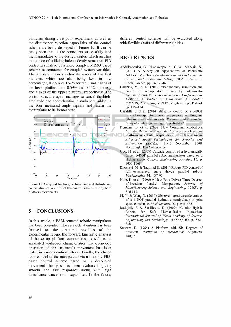
platforms during a set-point experiment, as well as the disturbance rejection capabilities of the control scheme are being displayed in Figure 10. It can be easily seen that all the controllers successfully lead the manipulator to the desired angles, which justifies the choice of utilizing independently structured PID controllers instead of a more complex MIMO based scheme to counteract for coupled system variables. The absolute mean steady-state errors of the first platform, which are also being kept in low percentages, 0.9% and 0.62% for the y and x axes of the lower platform and 0.59% and 0.56% for the y and x axes of the upper platform, respectively. The control structure again manages to cancel the high-amplitude and short-duration disturbances added in the four measured angle signals and return the manipulator to its former state.
Figure 10: Set-point tracking performance and disturbance cancellation capabilities of the control scheme during both platform movements.
5 CONCLUSIONS
In this article, a PAM-actuated robotic manipulator has been presented. The research attention has been focused on the structural novelties of the experimental set-up, the forward kinematic analysis of the set-up platform components, as well as its simulated workspace characteristics. The open-loop operation of the structure’s movement has been tested in various motion paterns. Finally, the closed loop control of the manipulator via a multiple PID-based control scheme based on a decoupled movement theorysis has been evaluated, giving smooth and fast responses along with high disturbance cancellation capabilites. In the future,
different control schemes will be evaluated along with flexible shafts of different rigidities.
REFERENCES
Andrikopoulos, G., Nikolakopoulos, G. & Manesis, S., (2011) A Survey on Applications of Pneumatic Artificial Muscles. 19th Mediterranean Conference on Control and Automation (MED), 20-23 June 2011, Corfu, Greece, pp. 1439-1446.
Calabria, M., et al. (2012) “Redundancy resolution and control of manipulators driven by antagonistic pneumatic muscles. 17th International Conference on Methods & Models in Automation & Robotics (MMAR), 27-30 August 2012, Międzyzdroje, Poland, pp. 119–124.
Cazalilla, J. et al. (2014) Adaptive control of a 3-DOF parallel manipulator considering payload handling and relevant parameter models. Robotics and Computer-Integrated Manufacturing, 30, p. 468-477.
Denkena, B. et al. (2008) New Compliant Mc-Kibben Actuator Driven by Pneumatic Actuators as a Hexapod Platform in Robotic Applications. 10th Workshop on Advanced Space Technologies for Robotics and Automation (ASTRA), 11-13 November 2008, Noordwijk, The Netherlands.
Guo, H. et al. (2007) Cascade control of a hydraulically driven 6-DOF parallel robot manipulator based on a sliding mode. Control Engineering Practice, 16, p. 1055-1068.
Khosravi, M. & Taghirad H. (2014) Robust PID control of fully-constrained cable driven parallel robots. Mechatronics, 24, p.87-97.
Ning, K. et al. (2006) A New Wire-Driven Three Degree-of-Freedom Parallel Manipulator. Journal of Manufacturing Science and Engineering, 128(3), p. 816-819.
Pi, Y. & Wang X. (2010) Observer-based cascade control of a 6-DOF parallel hydraulic manipulator in joint space coordinate. Mechatronics, 20, p. 648-655.
Radojicic J. & Surdilovic, D. (2009) Modular Hybrid Robots for Safe Human-Robot Interaction. International Journal of World Academy of Science, Engineering and Technology (WASET), 60, p. 832–838.
Stewart, D. (1965) A Platform with Six Degrees of Freedom. Institution of Mechanical Engineers. 180(15).
Output Disturbances
ICINCO�2014�-�11th�International�Conference�on�Informatics�in�Control,�Automation�and�Robotics
36