Resonance ionization image detectors: basic characteristics and potential applications
11
Resonance ionization image detectors: basic characteristics and potential applications O. I. Matveev, B. W. Smith, and J. D. Winefordner A type of spectrally selective imaging optical detector that is based on resonance ionization in an atomic vapor is proposed. It has the potential for improved spatial, spectral, and temporal resolutions com- pared with those of available techniques. Figures of merit are calculated and compared with those of existing techniques. Several potential applications such as the imaging of moving objects, ultrasonic fields, high-energy particle detection, and optical communications are discussed. © 1997 Optical Society of America Key words: Resonance ionization spectroscopy, resonance ionization image detectors. 1. Introduction The new trend in imaging science—spectrally re- solved imaging detectors and filters— continues to attract the increasing attention of researchers from many different fields of applied optics and spectroscopy. 1–3 Imaging with higher spectral reso- lution, limited only by the natural atomic linewidth, can be achieved with atomic resonance imaging spec- trometers and filters. It is understandable that atomic imaging detectors can have limited spectral ranges that correspond to the absorption frequencies of a few easily volatile elements. Nevertheless, as is shown below, even with such a limited spectral range, atomic resonance imaging detectors and filters can have a surprisingly broad range of useful applica- tions. A limited number of concepts and applications for imaging atomic filters and detectors have been de- scribed in the literature. Ultra-narrow-band atomic resonance ionization image detectors ~RIID’s! were first suggested for the detection of single atoms and molecules in the presence of strong background radi- ation. 4 An imaging atomic resonance monochroma- tor with atomic Cs vapor 5 has been suggested and experimentally verified for space communication sat- ellite tracking. A promising and interesting appli- cation for atomic and molecular filters is the detection of images of aerodynamic flow fields. 6 –10 Prospects for applications of atomic and molecular Faraday fil- ters for imaging purposes appear to be promising. Nonimaging variations of the Faraday atomic filter have currently found many useful applications for free-space and underwater communications systems, atmospheric temperature measurements, and laser lidar. 11–15 Other promising applications for atomic high-spectral-resolution image detectors can be found, for example, in the detection of images of Ra- man and Rayleigh spectra of scattered radiation from micro-objects and macro-objects. 16,17 In order to compare the figures of merit of the different types of narrow-band image detectors for the solution to a wide variety of practical problems, several characteristics should be specified: ~1! quantum efficiency q ~dimensionless!; ~2! intrinsic noise of the one-bit spatial element ~pixel! of the image detector N ~usually in units of electrons per second or electrons per pulse!; ~3! active working area A ~in square centimeters!; ~4! optical acceptance angle aperture V~in steradi- ans!; ~5! spatial resolution Dx ~in millimeters!; ~6! spectral bandwidth Dl ~in nanometers! or Dn ~in megahertz or gigahertz!; ~7! spectral working range S ~in gigahertz!; ~8! instrument function I~l!; ~9! temporal resolution Dt. It is shown that, compared with the figures of merit obtained with other methods and approaches, supe- rior figures of merit can be achieved for the proposed The authors are with the Department of Chemistry, University of Florida, Gainesville, Florida 32611. Received 19 February 1997; revised manuscript received 9 July 1997. 0003-6935y97y348833-11$10.00y0 © 1997 Optical Society of America 1 December 1997 y Vol. 36, No. 34 y APPLIED OPTICS 8833
-
Upload
independent -
Category
Documents
-
view
0 -
download
0
Transcript of Resonance ionization image detectors: basic characteristics and potential applications
Resonance ionization image detectors:basic characteristics and potential applications
O. I. Matveev, B. W. Smith, and J. D. Winefordner
A type of spectrally selective imaging optical detector that is based on resonance ionization in an atomicvapor is proposed. It has the potential for improved spatial, spectral, and temporal resolutions com-pared with those of available techniques. Figures of merit are calculated and compared with those ofexisting techniques. Several potential applications such as the imaging of moving objects, ultrasonicfields, high-energy particle detection, and optical communications are discussed. © 1997 Optical Societyof America
Key words: Resonance ionization spectroscopy, resonance ionization image detectors.
1. Introduction
The new trend in imaging science—spectrally re-solved imaging detectors and filters—continues toattract the increasing attention of researchers frommany different fields of applied optics andspectroscopy.1–3 Imaging with higher spectral reso-lution, limited only by the natural atomic linewidth,can be achieved with atomic resonance imaging spec-trometers and filters. It is understandable thatatomic imaging detectors can have limited spectralranges that correspond to the absorption frequenciesof a few easily volatile elements. Nevertheless, as isshown below, even with such a limited spectral range,atomic resonance imaging detectors and filters canhave a surprisingly broad range of useful applica-tions.
A limited number of concepts and applications forimaging atomic filters and detectors have been de-scribed in the literature. Ultra-narrow-band atomicresonance ionization image detectors ~RIID’s! werefirst suggested for the detection of single atoms andmolecules in the presence of strong background radi-ation.4 An imaging atomic resonance monochroma-tor with atomic Cs vapor5 has been suggested andexperimentally verified for space communication sat-ellite tracking. A promising and interesting appli-cation for atomic and molecular filters is the detection
The authors are with the Department of Chemistry, Universityof Florida, Gainesville, Florida 32611.
Received 19 February 1997; revised manuscript received 9 July1997.
0003-6935y97y348833-11$10.00y0© 1997 Optical Society of America
of images of aerodynamic flow fields.6–10 Prospectsfor applications of atomic and molecular Faraday fil-ters for imaging purposes appear to be promising.Nonimaging variations of the Faraday atomic filterhave currently found many useful applications forfree-space and underwater communications systems,atmospheric temperature measurements, and laserlidar.11–15 Other promising applications for atomichigh-spectral-resolution image detectors can befound, for example, in the detection of images of Ra-man and Rayleigh spectra of scattered radiation frommicro-objects and macro-objects.16,17
In order to compare the figures of merit of thedifferent types of narrow-band image detectors forthe solution to a wide variety of practical problems,several characteristics should be specified:
~1! quantum efficiency q ~dimensionless!;~2! intrinsic noise of the one-bit spatial element
~pixel! of the image detector N ~usually in units ofelectrons per second or electrons per pulse!;
~3! active working area A ~in square centimeters!;~4! optical acceptance angle aperture V ~in steradi-
ans!;~5! spatial resolution Dx ~in millimeters!;~6! spectral bandwidth Dl ~in nanometers! or Dn ~in
megahertz or gigahertz!;~7! spectral working range S ~in gigahertz!;~8! instrument function I~l!;~9! temporal resolution Dt.
It is shown that, compared with the figures of meritobtained with other methods and approaches, supe-rior figures of merit can be achieved for the proposed
1 December 1997 y Vol. 36, No. 34 y APPLIED OPTICS 8833

RIID’s. We briefly review the principle of operationand the important figures of merit of the RIID.
2. Principles of Operation and Basic Characteristics
A. Principle of the Resonance Ionization Image DetectorOperation
The concept and operational principles of the RIIDhave not been analyzed in the accessible literatureand so are discussed below.
As an example, let us consider the feasibility of aRIID used for the measurement of some spectralcharacteristics of, for example, high-pressure com-bustion products. Figure 1 shows a schematic of alaser lidar for such a measurement. The idea ofsuch a measurement with the RIID is to form animage of the observed high-pressure combustion zonethat is illuminated by narrow-band laser radiationwith a resonance wavelength l1 on the flat ~planar!surface of the RIID cell and to detect the number andthe position of charged particles created as a result ofselective ionization of atoms that have absorbed res-onance radiation close to the front surface of theRIID. Depending on the task to be solved, the wave-length of the laser l1 should be tuned to the centralwavelength or in the vicinity of a resonance transi-tion of the atomic vapor in the RIID cell. To ionizethe atoms that absorb resonance radiation in theRIID cell, it must be illuminated by additional laserradiation. For example, consider the case if l1 istuned close to the resonance transition of Hg, l1 5253.7 nm, in such a way that a spectrum of Doppler-,Raman-, or Rayleigh-shifted scattering radiationshould be centered exactly in the center of l1.17
When the RIID cell is filled with Hg atoms, the wave-lengths of the additional laser radiation with l2 andl3 are as depicted in the energy-level diagram shownin Fig. 2.
As has been shown,18 when a wavelength schemesuch as that shown in Fig. 2 is used for a Hg reso-nance ionization detector ~RID! cell, a high quantumefficiency and low noise level can be attained for the
Fig. 1. Schematic of the RIID.
8834 APPLIED OPTICS y Vol. 36, No. 34 y 1 December 1997
detection of resonance radiation. Charged particlesin the RIID cell can produce an image, for example,after acceleration in an electric field of 30–40 kV in amanner similar to the behavior of image intensifi-ers,19 which can provide a spatial resolution of 0.1–0.03 mm. Another approach for image productioncan be realized with the method of emission detectionof the laser-enhanced ionization signal.20–25 In thiscase, a spatial imaging resolution of 0.2 mm can beobtained.26,27 Information about the temperatureand the concentration of molecules in the area illu-minated by l1 can be obtained from some simplemathematical calculations if one knows the neces-sary parameters of molecular scattering28 or if onehas measured the scattered signal from a referencecell filled with a variable known pressure and tem-perature of the unperturbed gas under investigation.Major species in the high-pressure combustion zonecan be detected with the methods of Raman spectros-copy or coherent anti-Stokes Raman spectroscopy.Another promising method for the determination ofthe coordinates of charged particles is the approachused in multiwire drift chambers.29
A RIID cell filled with monoisotopic Hg atoms atlow pressure ~for example, the even–even isotopeHg200! and at room temperature will have a spectralresolution approaching 1 GHz, limited only by Dopp-ler broadening. By scanning the frequency of theprobe laser l1 in the vicinity of 253.7 nm, one canobtain complete information about the spectral char-acteristics of the scattering high-pressure gas. It isnecessary to note that the spectral resolution of theRIID can be greatly increased if one uses a Doppler-free scheme of atomic photoionization.30,31 In thiscase, the resolution, limited by the natural linewidthof the Hg atom transitions, can approach severalmegahertz. In this mode of measurement, separateinformation about aerosol and molecular scatteringcan be obtained. It is important to note that thisspectral resolution cannot be attained with absorp-tion filter approaches.6,9
Fig. 2. Scheme for Hg atom excitation and ionization.
Let us consider in detail the figures of merit of theRIID described above.
B. Quantum Efficiency
This characteristic of a RIID can be evaluated in thesame manner as the quantum efficiency of RID’s.32
To a first approximation, it can be described by
q 5 ah, (1)
where a is the absorption factor of atomic or molec-ular vapor in the RIID cell and h is the efficiency ofionization of atoms excited by the additional laser.A value for h of 0.1 was achieved experimentally fora Hg RID.18 However, if one increases the energy oflaser radiation there is no fundamental limitation toobtaining an efficiency near unity.33 It was recentlyshown34 that 20-fold lower power is necessary whenan optimized scheme is used for the ionization of Hgto obtain the same efficiency of ionization comparedwith the traditional scheme in which the 435.8-nmwavelength18 is used as l2. The value of a for thecenter of the line, which can be considered as themaximum possible efficiency for ionization of exitedatoms, is given by
a 5 1 2 exp~2nsl !, (2)
where n is the atomic number density ~in inversecubic centimeters!, s is the cross section of resonanceabsorption ~in square centimeters!, and l is the opti-cal path length ~in centimeters!. For example, forHg at room temperature, s equals 6 3 10213 cm2 andthe number density of the mercury vapor is 4.3 3 1013
atoms cm23.35
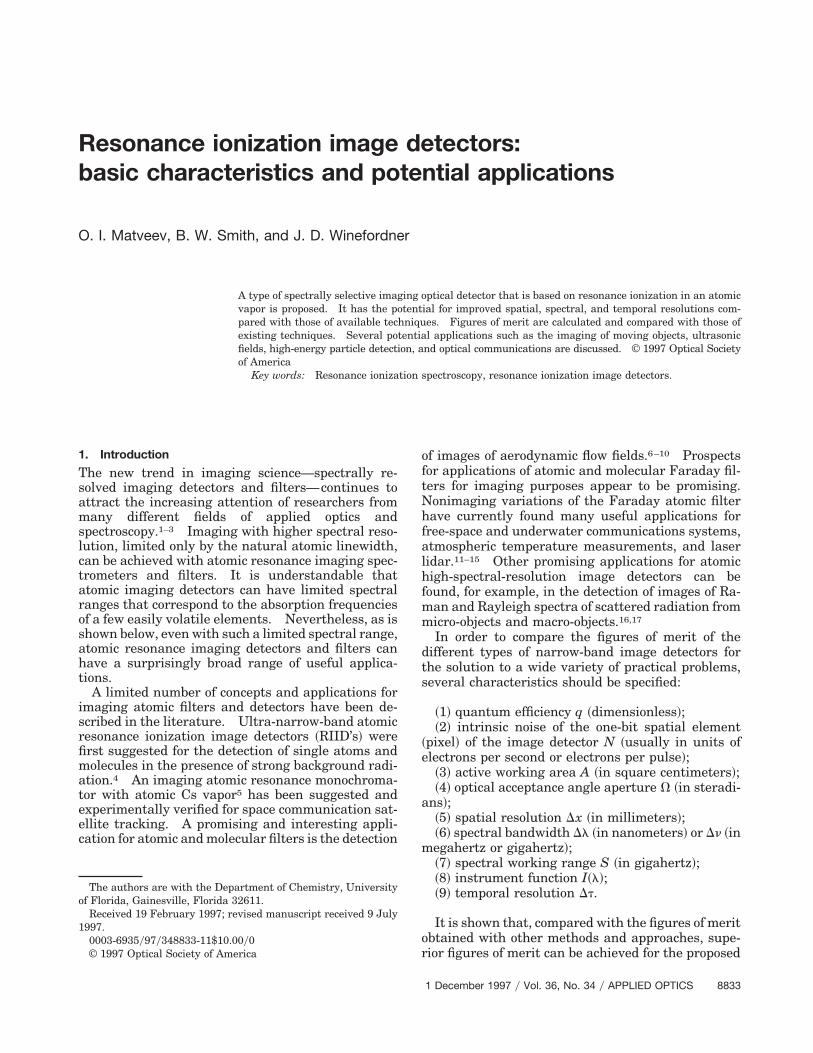
In Fig. 3, the dependence of q versus l is shown forHg atomic vapor at 21 °C. As can be seen, even foran RIID thickness of 0.1 cm, a quantum efficiency ofmore than 90% can be obtained.
An atomic vapor density sufficient to provide agreater than 60%–70% quantum efficiency in a 1-cmcell can be obtained for at least 23 elements at tem-peratures below 500 °C ~He, Li, Ne, Na, Mg, Ar, K,
Fig. 3. Absorbance versus path length for a room-temperature Hgcell.
Ca, Zn, Kr, Rb, Sr, Cd, Xe, Cs, Ba, Tl, Pb, Bi, Sm, Eu,Tm, Yb!.36 It would also be interesting to study thefeasibility of constructing a RIID cell filled with amolecular gas at room temperature in order to detectradiation in the IR region. Thus it can be concludedthat, in principle, an optimized RIID can achieve aquantum efficiency of near unity for a wide variety ofpossible elements and wavelengths.
C. Intrinsic Noise
The sources of noise that can limit the sensitivity ofthe RIID are practically the same as those for RID’s,which have been analyzed.30,32 They are mostlydue to nonselective multiphoton ionization of atoms,photoionization of molecular dimers created from at-oms in the RID cell, and the thermal population of thefirst resonance state. However, as was shown byMatveev et al.,32 when an appropriate ionizationscheme and an optimum design of the RID cell arechosen, a limit of detection of 1–5 resonance quantaper second in a 1-cm3 volume can be obtained ~signal-to-noise ratio 5 1!. When this figure of merit isapplied to the RIID, it can be concluded that for anindividual pixel of the RIID with an area aRIID thelimit of detection can be aRIIDyARID smaller, whereARID is the area of the RID. Taking into accountthat, for the RIID, the ratio aRIIDyARID can be 1023–1024, we can conclude that the single-pixel intrinsicnoise level for the RIID does not exceed 1022–1023
electronsys, which is much better than that for anyexisting imaging detector.
D. Active Working Area and Acceptance Angle Aperture
It is clear that these figures of merit can also be asgood as the best-known image detectors. There is notechnical limitation to the construction of a RIID witha working area of even several square meters. Theacceptance angle aperture is expected to be limited byonly the angle of total reflection from the input sur-face of the RIID, i.e., one should expect an V value ofalmost 2p sr.
E. Spatial Resolution
The standard spatial resolutions of modern CCDcameras37 and image intensifiers19 are in the range0.02–0.03 mm. From simplistic considerations, animage detector in which electrons are created in thevolume of the RIID rather than from the surface of animage intensifier should have essentially poorer res-olution. However, the calculations presented belowshow that, under certain conditions, the spatial res-olution of the RIID with an atomic vapor can be of thesame order as that obtained by image intensifiers andCCD cameras.
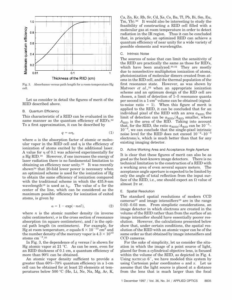
For the sake of simplicity, let us consider the situ-ation in which the image of a point source of light,placed far from a cylindrical objective lens, is focusedwithin the volume of the RIID, as depicted in Fig. 4.Using MATHCAD 61, we have modeled this system byusing Cartesian polar coordinates a and x. Let usassume that the light source is placed at a distancefrom the lens that is much larger than the focal
1 December 1997 y Vol. 36, No. 34 y APPLIED OPTICS 8835
length f of the lens. In this case, all rays reachingthe lens can be considered parallel with I0 intensityper unit of lens length. If r ,, f ~a are small! thelight flux within an angle da can be given as
dE0 5I0
2a0da. (3)
The more exact formula for arbitrary r and f is dif-ferent: dE0 5 I0$ fy@2r cos2~a!#%da. However, forthe sake of simplicity, we use formula ~3!. For anarbitrary beam R and for a region of the RIID withthickness c, the energy dEA absorbed within an infi-nitely thin layer dx is given by
dEA 5 dE0 exp~2kl !kS dxsin aD , (4)
where k 5 ns and l 5 @cycos~a!# 2 @xysin~a!#. Aftersubstitution and taking into account that a0 5 atan~ryf !, we can write the dependence of the energyEA~x! on the coordinate x as
dEA~x! 5I0
2a tan~ryf ! *a1
a2
exp~2kl !dx
sin ada. (5)
It is understandable from Fig. 4 that a1 5 a tan~xyc!and a2 5 a tan~ryf !. By using the same approach,we can calculate the dependence of dEA~x!ydx for aregion of the RIID with thickness p 2 c. In Appen-dixes 1 and 2, the absorption by layer c is described bythe integral W~c, x! and the absorption by layer p 2 cis described by the function K~c, x!.
The final formulas for two point sources of radiationand the program are shown in Appendix 2. In Figs. 5~a!and 5~b! the results of the simulation are shown for a HgRIID with a thickness p 5 2 mm. The calculations wereperformed for the case of atomic Hg vapor at room tem-perature ~k 5 2.58 mm21! and approximately 40 °C ~k 58 mm21!. The distance between peaks is 0.2 mm. Asone can see, even for this small distance, for both casesone can observe well-resolved peaks. Further simula-tions showed that resolved peaks were observed until thedistance between them reached 0.035 mm. In Fig. 5~c!,
Fig. 4. Model used for simulation of RIID spatial resolution.
8836 APPLIED OPTICS y Vol. 36, No. 34 y 1 December 1997
two peaks are shown that have a distance between themof 0.044 mm. The different heights of the peaks wereproduced because of an error in the calculations by MATH-CAD.
It is interesting to note in Fig. 5~a! that, indepen-dently of the depth of the focused image, one canobserve distinguishable peaks even at low vapor den-sity. In the heated RIID, which has a threefold
Fig. 5. ~a! Calculated spatial response of the RIID, 25 °C; ~b!calculated spatial response of the RIID, 40 °C; ~c! calculated spatialresponse of the RIID with images separated by 0.044 mm.

larger vapor density ~k 5 8 mm21!, lines can be dis-tinguished only for an image focused within 0–0.6mm from the upper surface of the RIID. From thesesimulations it can be concluded that the main param-eters affecting the resolution of the RIID are theatomic vapor density, the focal length of the objective,and the position of the focal plane within RIID.Also, the simulation showed that when the parame-ters of the RIID cell and objective are optimized, aspatial resolution Dx can be obtained that is of theorder of what is available with the best commercialimage detectors.
F. Spectral Bandwidth, Spectral Working Range, andInstrument Function
The spectral bandwidth of the RIID is determined bythe linewidth of the atomic or the molecular vaporabsorption in the RIID cell. Normally, if there is avacuum or low-pressure gas in the RIID cell, it can beapproximated by a Doppler-broadened line profile.For example, in the case of Hg at room temperatureit is 1.027 GHz. However, the spectral resolution ofthe RIID is, in general, not limited by the Dopplerlinewidth. An important feature of the RIID is that,in principle, a spectral bandwidth approaching thenatural linewidth can be obtained.30 For the 6 3P0
0
level of Hg, the natural lifetime t1 5 118 ns and itsnatural linewidth DnN 5 1⁄2 pt, i.e., DnN 5 1.35 MHz.However, it is important to point out that the accep-tance angle aperture under Doppler-free measure-ment conditions will be greatly reduced and cannot bemore than
VN <2p~DnR 1 DnN!
DnD, (6)
where DnR is the required experimental spectralresolution, which of course must be less than DnD.Another technical demand for Doppler-free measure-ments that can make the construction of the RIIDcomparatively more complicated is the necessity todirect the laser beam collinearly with the beam car-rying the imaging information. On the other hand,under Doppler-free measurement conditions, the re-quired energy of the additional laser EADD is reducedand the energy required for saturating the atomictransition is DnDyDnR times smaller.
The spectral working range of the RIID is limitedby the linewidth of the atomic transition. However,it can be increased, as in the case of Hg, when theatom has several even–even isotopes. In this case,for example, when the Hg 196, 198, 200, 202, and 204isotopes are used, the spectral working range is in-creased to 19–20 GHz. The long lifetime of the 6 3P0
0
state of Hg also permits an alternative high-speed,high-resolution ~approximately 50-MHz! measure-ment scheme over a comparatively wide spectralrange ~;1 GHz!. By sweeping the frequency of theadditional laser at l2 within a time interval of t1 5118 ns ~lifetime of the Hg 6 3P0
0 state!, one can scanthe working spectral wavelength of the RIID withinthe Doppler-broadened line ~1 GHz!. In this case,
one can expect that the RIID can measure a signalwith a spectral resolution of DnS 5 DnD~t2yt1!, wheret2 is the lifetime of the 7s 3S1 Hg state. This isimportant, for example, for the measurement of im-ages of aerodynamic flow or shock waves with hightemporal and spectral resolution.
Another way to increase the spectral range is totake advantage of the Stark shift of high-lying orRydberg states. For example, the 8s 2S1y2 level of Kcan be tuned 800 GHz in a modest electric field ~up to50 kVycm! in the vicinity of the 532-nm Nd:YAG laserwavelength, which is important for many practicalapplications.12 In the case of a K RIID, atoms canalso be excited to the 8s 2S1y2 ~E 5 31 765 cm21! stateand ionized by an additional laser with a wavelengthcorresponding to the transitions between 8s 2S1y2 3np 2P1y2,3y2 ~where n ' 14–30, E 5 34 283–34 872cm21!. The corresponding wavelength l of this ad-ditional laser radiation would be in the region from 4to 3.2 mm.
In general, the instrument function of the RIID canbe described by the Voigt function. This means thatif the atomic vapor is placed in a vacuum, the lineshape in the vicinity of center is described by anexponential function characterized by Doppler broad-ening with line wings that are described by a Lorent-zian function. An important feature of the RIID isthat its spectral response function can be modifiedand improved with atomic filters, atomic Faradayfilters, or interferometers.
Using MATHCAD, we modeled the spectral character-istics of the Hg RIID, modified by an isotopic atomicfilter. In Fig. 6 the results of the instrumental func-tion calculation for a Hg200 RIID vapor cell areshown. It is clearly shown that, in the vicinity of theHg200 isotope RIID line, even when nonoptimized fil-ters with Hg 196, 198, 202, and 204 isotopes are used,the background can be suppressed by an order ofmagnitude. Such filters can also improve the totalnoise bandwidth of the RIID.
The instrument function of a RIID for a low-pressure cell in the spectral range of 600 GHz ~20cm21! is plotted in Fig. 7. Note that the background
Fig. 6. Response function of the RIID with an isotopic Hg filter.
1 December 1997 y Vol. 36, No. 34 y APPLIED OPTICS 8837

is suppressed by almost 12 orders of magnitude at 20cm21 from the center of the line. This is almost atthe same level as that attained by the best availabletriple monochromator. If the linewidth of the RIIDequals the natural linewidth, the total noise-equivalent bandwidth of this image detector will ap-proach 2.1 MHz. This is more than 2 orders ofmagnitude smaller than what is achievable withatomic Faraday filters.
G. Temporal Resolution
The time resolution DtRIID of the RIID is limited pri-marily by two factors: first, by the electron time offlight tF from the zone illuminated by the additionallaser to the luminescent screen and, second, by therate of atom ionization RADD due to the additionallaser radiation:
DtRIID 5 FtF2 1 S 1
RADDD2G1y2
. (7)
The value of tF is given by
tF 5 d3 2
S emDV4
1y2
, (8)
where d and V are the spacing ~in meters! and thevoltage ~in volts! between electrodes in the RIID cell,respectively, and e and m correspond to the charge ~incoulombs! and the mass ~in kilograms! of the elec-tron, respectively. For electrodes with a 1-cm spac-ing and an applied field of 30 kV, tF is estimated fromthis formula to be 200 ps. It is apparent that theelectron flight time will not be the main factor limit-ing the temporal resolution of the RIID.
It is the rate of ionization achievable and the life-time of the excited state involved that limit the tem-poral response. In order to obtain a reasonably highefficiency of excited atom ionization in an RIID cell,RADD should be no smaller than 1yt2 ~considering thecase of Hg!. This means that the time resolution ofthe Hg RIID can be at least 9 ns. It is understand-
Fig. 7. Spectral response function for the RIID.
8838 APPLIED OPTICS y Vol. 36, No. 34 y 1 December 1997
able that this time resolution can be improved withan additional laser of higher power to produce ahigher rate of atom ionization. However, in thiscase, noise will increase because of nonselective pho-toionization. For every specific case, a more detailedinvestigation needs to be made so we can understandhow much the time resolution can be improved com-pared with what is dictated by t2.
As one can see, the RIID can have superior figuresof merit compared with those of similar techniquesand should prove useful for many potential practicalapplications. It is also important to emphasize thatfor cases in which rather large levels of scatteredradiation are being measured or for experiments in-volving feasibility studies, a simpler resonance imag-ing monochromator ~RIM! can be used jointly withthe RIID.4,5,9
Let us compare some figures of merit of the RIMand the RIID. One disadvantage of the RIID is itsrelative complexity and the necessity of using an ad-ditional laser of rather high power. However, theRIM described by Korevaar et al.5 cannot be used inthe Doppler-free mode because the Cs that is usedhas several hyperfine structure lines and, because ofthis, the spectrum that is acquired cannot be inter-preted without uncertainties. The method de-scribed by Finkelstein et al.9 used only one Hgtransition and therefore also cannot be Doppler free.Its spectral resolution is limited by Doppler broaden-ing and equals 1 GHz. A RIM containing an even–even isotope of Hg can have some figures of meritssimilar to those of the RIID. The principle of the HgRIM operation is similar to what has been describedby Finkelstein et al.9 and by Korevaar et al.5 and isillustrated in Fig. 8 to detect, for example, aerody-namic flow fields. The geometric positioning of theaerodynamic flow region, the laser beams, and thedetecting apparatus is illustrated schematically andin a real situation can be changed in accordance withthe needs of the particular measurement. A laserwith l1 5 253.7 nm irradiates the aerodynamic flowunder investigation. The laser beam used to irradi-ate the entire cross section of flow can have planargeometry. The objective lens forms an image of thearea irradiated by the laser onto the surface of the Hgvapor filter ~containing an even–even Hg isotope!
Fig. 8. Doppler-free atomic RIM.
that is irradiated colinearly by laser beams with l2 5435.8 nm. Hg atoms excited by l2 into the 7 3S1state will emit fluorescent light with a green wave-length of 546.0 nm, as shown in Fig. 2. The imageproduced by this green light can be detected by avideo imaging system. If a UV filter is placed infront of the Hg cell, blocking visible radiation, and agreen filter is placed behind the cell, blocking the UVand the 435.8-nm laser beam, the whole system willdetect and image only resonance Hg radiation at253.7 nm. Apparently, if one uses narrow-band ra-diation at 435.8 nm, the total spectral resolution ofthe RIM will be limited by the 8.5-ns lifetime of the7 3S1 state and cannot be better then ;19 MHz. Itis also expected that the RIM will exhibit potentialinterferences from the 435.8-nm laser beam and willhave generally more than 1 order of magnitudepoorer signal-to-noise ratio. Compared with theRIID technique, the RIM is considerably simpler andcan be used in preliminary laboratory experiments toevaluate the potential characteristics of the RIID asan ultra-narrow-band image detector.
3. Potential Application
Numerous potential practical applications could existfor the RIID. A comprehensive evaluation of theseis beyond the scope of this paper but we do point outseveral promising possibilities.
A. Moving Object Detection
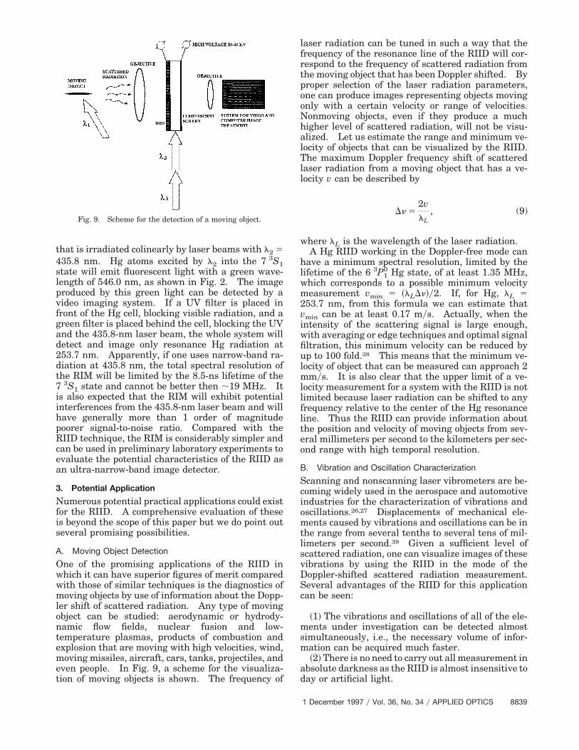
One of the promising applications of the RIID inwhich it can have superior figures of merit comparedwith those of similar techniques is the diagnostics ofmoving objects by use of information about the Dopp-ler shift of scattered radiation. Any type of movingobject can be studied: aerodynamic or hydrody-namic flow fields, nuclear fusion and low-temperature plasmas, products of combustion andexplosion that are moving with high velocities, wind,moving missiles, aircraft, cars, tanks, projectiles, andeven people. In Fig. 9, a scheme for the visualiza-tion of moving objects is shown. The frequency of
Fig. 9. Scheme for the detection of a moving object.
laser radiation can be tuned in such a way that thefrequency of the resonance line of the RIID will cor-respond to the frequency of scattered radiation fromthe moving object that has been Doppler shifted. Byproper selection of the laser radiation parameters,one can produce images representing objects movingonly with a certain velocity or range of velocities.Nonmoving objects, even if they produce a muchhigher level of scattered radiation, will not be visu-alized. Let us estimate the range and minimum ve-locity of objects that can be visualized by the RIID.The maximum Doppler frequency shift of scatteredlaser radiation from a moving object that has a ve-locity v can be described by
Dn 52vlL
, (9)
where lL is the wavelength of the laser radiation.A Hg RIID working in the Doppler-free mode can
have a minimum spectral resolution, limited by thelifetime of the 6 3P1
0 Hg state, of at least 1.35 MHz,which corresponds to a possible minimum velocitymeasurement vmin 5 ~lLDn!y2. If, for Hg, lL 5253.7 nm, from this formula we can estimate thatvmin can be at least 0.17 mys. Actually, when theintensity of the scattering signal is large enough,with averaging or edge techniques and optimal signalfiltration, this minimum velocity can be reduced byup to 100 fold.38 This means that the minimum ve-locity of object that can be measured can approach 2mmys. It is also clear that the upper limit of a ve-locity measurement for a system with the RIID is notlimited because laser radiation can be shifted to anyfrequency relative to the center of the Hg resonanceline. Thus the RIID can provide information aboutthe position and velocity of moving objects from sev-eral millimeters per second to the kilometers per sec-ond range with high temporal resolution.
B. Vibration and Oscillation Characterization
Scanning and nonscanning laser vibrometers are be-coming widely used in the aerospace and automotiveindustries for the characterization of vibrations andoscillations.26,27 Displacements of mechanical ele-ments caused by vibrations and oscillations can be inthe range from several tenths to several tens of mil-limeters per second.39 Given a sufficient level ofscattered radiation, one can visualize images of thesevibrations by using the RIID in the mode of theDoppler-shifted scattered radiation measurement.Several advantages of the RIID for this applicationcan be seen:
~1! The vibrations and oscillations of all of the ele-ments under investigation can be detected almostsimultaneously, i.e., the necessary volume of infor-mation can be acquired much faster.
~2! There is no need to carry out all measurement inabsolute darkness as the RIID is almost insensitive today or artificial light.
1 December 1997 y Vol. 36, No. 34 y APPLIED OPTICS 8839
~3! With telescopic optics, images of small parts ofthe device under investigation can be observed re-motely.
C. Detection and Imaging of Ultrasonic Fields
The visualization of ultrasonic fields on the surfacesand within the volume of solid, liquid, and gaseousmediums is important for many practical applica-tions. Recently, several new ways have been foundfor using laser radiation to provide such avisualization.40–44 As mentioned by Wang et al.,43
there are several ways to visualize ultrasonic fields.The density or refractive-index variations induced byan ultrasound wave can modulate at the ultrasonicfrequency light that is directed through the medium.Ultrasound waves can generate particle displace-ment in the volume or on the surface that can lead tothe variations in the speckle interference image. Asin the above case, ultrasonic fields can be measuredbased on the variations of Doppler-shifted light thatis reflected or scattered from moving surface ele-ments interacting with the ultrasonic field. All theconventional methods require spatial scanning overcertain periods of time.39–43 An advantage of theRIID is its ability to image intensity distributions ofultrasonic fields without spatial scanning. One ofthe most interesting cases would be realized whenthe frequency of the ultrasound nUS is higher than thespectral resolution of the RIID, nUS . DnS. In thiscase, by tuning the probe laser to the frequency nL 5nRES 6 nUS in the vicinity of the resonance atomictransition nRES, one can reject the scattered laserradiation background from surfaces not interactingwith the ultrasonic field. Thus, when the RIID isused, background-free images of ultrasound fieldscan be produced.
D. Analytical Imaging Spectroscopy
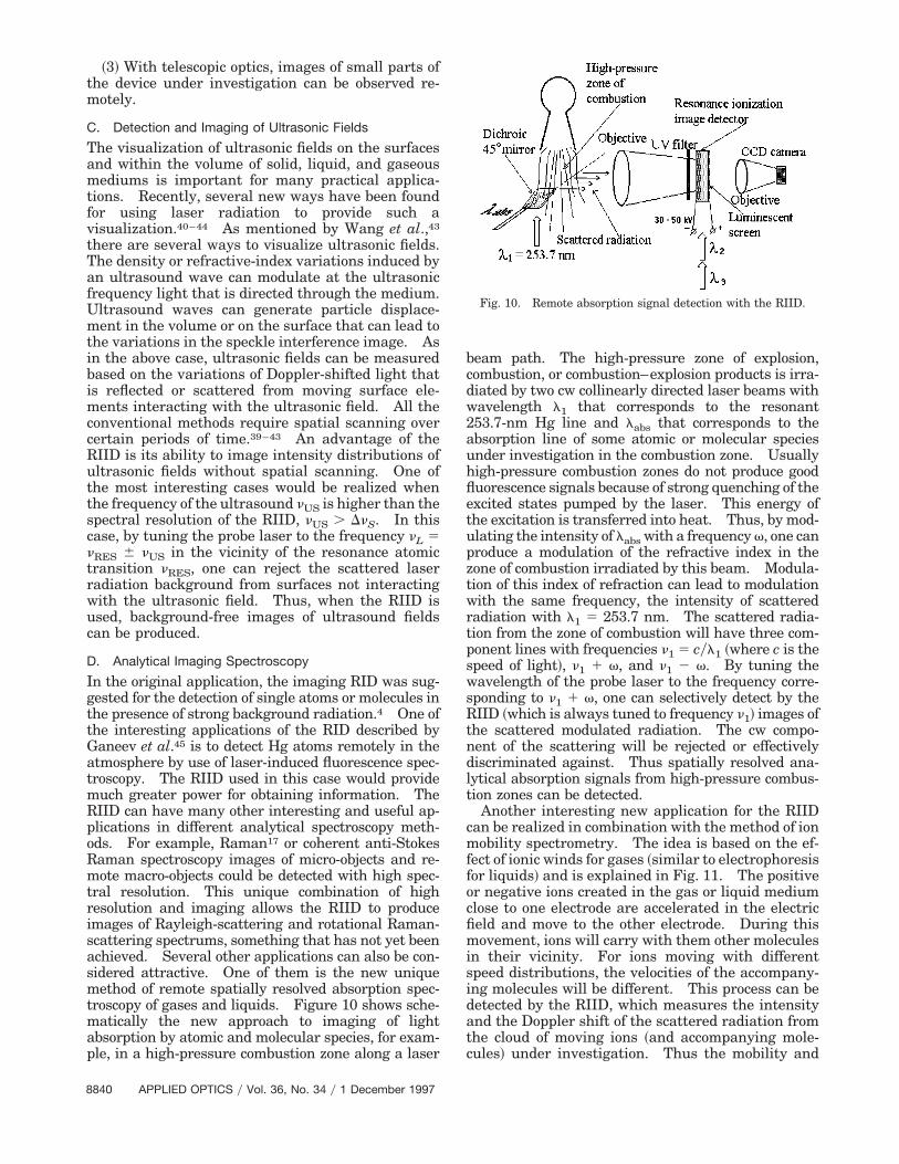
In the original application, the imaging RID was sug-gested for the detection of single atoms or molecules inthe presence of strong background radiation.4 One ofthe interesting applications of the RID described byGaneev et al.45 is to detect Hg atoms remotely in theatmosphere by use of laser-induced fluorescence spec-troscopy. The RIID used in this case would providemuch greater power for obtaining information. TheRIID can have many other interesting and useful ap-plications in different analytical spectroscopy meth-ods. For example, Raman17 or coherent anti-StokesRaman spectroscopy images of micro-objects and re-mote macro-objects could be detected with high spec-tral resolution. This unique combination of highresolution and imaging allows the RIID to produceimages of Rayleigh-scattering and rotational Raman-scattering spectrums, something that has not yet beenachieved. Several other applications can also be con-sidered attractive. One of them is the new uniquemethod of remote spatially resolved absorption spec-troscopy of gases and liquids. Figure 10 shows sche-matically the new approach to imaging of lightabsorption by atomic and molecular species, for exam-ple, in a high-pressure combustion zone along a laser
8840 APPLIED OPTICS y Vol. 36, No. 34 y 1 December 1997
beam path. The high-pressure zone of explosion,combustion, or combustion–explosion products is irra-diated by two cw collinearly directed laser beams withwavelength l1 that corresponds to the resonant253.7-nm Hg line and labs that corresponds to theabsorption line of some atomic or molecular speciesunder investigation in the combustion zone. Usuallyhigh-pressure combustion zones do not produce goodfluorescence signals because of strong quenching of theexcited states pumped by the laser. This energy ofthe excitation is transferred into heat. Thus, by mod-ulating the intensity of labs with a frequency v, one canproduce a modulation of the refractive index in thezone of combustion irradiated by this beam. Modula-tion of this index of refraction can lead to modulationwith the same frequency, the intensity of scatteredradiation with l1 5 253.7 nm. The scattered radia-tion from the zone of combustion will have three com-ponent lines with frequencies n1 5 cyl1 ~where c is thespeed of light!, n1 1 v, and n1 2 v. By tuning thewavelength of the probe laser to the frequency corre-sponding to n1 1 v, one can selectively detect by theRIID ~which is always tuned to frequency n1! images ofthe scattered modulated radiation. The cw compo-nent of the scattering will be rejected or effectivelydiscriminated against. Thus spatially resolved ana-lytical absorption signals from high-pressure combus-tion zones can be detected.
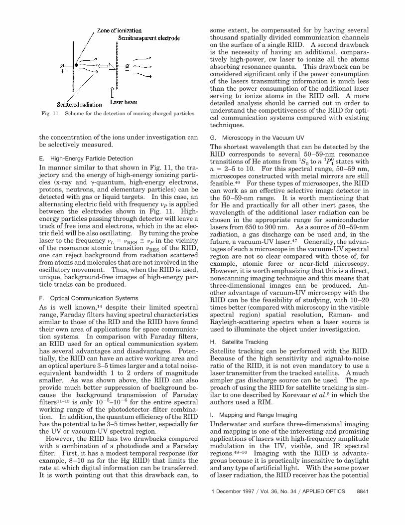
Another interesting new application for the RIIDcan be realized in combination with the method of ionmobility spectrometry. The idea is based on the ef-fect of ionic winds for gases ~similar to electrophoresisfor liquids! and is explained in Fig. 11. The positiveor negative ions created in the gas or liquid mediumclose to one electrode are accelerated in the electricfield and move to the other electrode. During thismovement, ions will carry with them other moleculesin their vicinity. For ions moving with differentspeed distributions, the velocities of the accompany-ing molecules will be different. This process can bedetected by the RIID, which measures the intensityand the Doppler shift of the scattered radiation fromthe cloud of moving ions ~and accompanying mole-cules! under investigation. Thus the mobility and
Fig. 10. Remote absorption signal detection with the RIID.
the concentration of the ions under investigation canbe selectively measured.
E. High-Energy Particle Detection
In manner similar to that shown in Fig. 11, the tra-jectory and the energy of high-energy ionizing parti-cles ~x-ray and g-quantum, high-energy electrons,protons, neutrons, and elementary particles! can bedetected with gas or liquid targets. In this case, analternating electric field with frequency nP is appliedbetween the electrodes shown in Fig. 11. High-energy particles passing through detector will leave atrack of free ions and electrons, which in the ac elec-tric field will be also oscillating. By tuning the probelaser to the frequency nL 5 nRES 6 nP in the vicinityof the resonance atomic transition nRES of the RIID,one can reject background from radiation scatteredfrom atoms and molecules that are not involved in theoscillatory movement. Thus, when the RIID is used,unique, background-free images of high-energy par-ticle tracks can be produced.
F. Optical Communication Systems
As is well known,14 despite their limited spectralrange, Faraday filters having spectral characteristicssimilar to those of the RID and the RIID have foundtheir own area of applications for space communica-tion systems. In comparison with Faraday filters,an RIID used for an optical communication systemhas several advantages and disadvantages. Poten-tially, the RIID can have an active working area andan optical aperture 3–5 times larger and a total noise-equivalent bandwidth 1 to 2 orders of magnitudesmaller. As was shown above, the RIID can alsoprovide much better suppression of background be-cause the background transmission of Faradayfilters11–15 is only 1025–1026 for the entire spectralworking range of the photodetector–filter combina-tion. In addition, the quantum efficiency of the RIIDhas the potential to be 3–5 times better, especially forthe UV or vacuum-UV spectral region.
However, the RIID has two drawbacks comparedwith a combination of a photodiode and a Faradayfilter. First, it has a modest temporal response ~forexample, 8–10 ns for the Hg RIID! that limits therate at which digital information can be transferred.It is worth pointing out that this drawback can, to
Fig. 11. Scheme for the detection of moving charged particles.
some extent, be compensated for by having severalthousand spatially divided communication channelson the surface of a single RIID. A second drawbackis the necessity of having an additional, compara-tively high-power, cw laser to ionize all the atomsabsorbing resonance quanta. This drawback can beconsidered significant only if the power consumptionof the lasers transmitting information is much lessthan the power consumption of the additional laserserving to ionize atoms in the RIID cell. A moredetailed analysis should be carried out in order tounderstand the competitiveness of the RIID for opti-cal communication systems compared with existingtechniques.
G. Microscopy in the Vacuum UV
The shortest wavelength that can be detected by theRIID corresponds to several 50–59-nm resonancetransitions of He atoms from 1S0 to n 1P1
0 states withn 5 2–5 to 10. For this spectral range, 50–59 nm,microscopes constructed with metal mirrors are stillfeasible.46 For these types of microscopes, the RIIDcan work as an effective selective image detector inthe 50–59-nm range. It is worth mentioning thatfor He and practically for all other inert gases, thewavelength of the additional laser radiation can bechosen in the appropriate range for semiconductorlasers from 650 to 900 nm. As a source of 50–59-nmradiation, a gas discharge can be used and, in thefuture, a vacuum-UV laser.47 Generally, the advan-tages of such a microscope in the vacuum-UV spectralregion are not so clear compared with those of, forexample, atomic force or near-field microscopy.However, it is worth emphasizing that this is a direct,nonscanning imaging technique and this means thatthree-dimensional images can be produced. An-other advantage of vacuum-UV microscopy with theRIID can be the feasibility of studying, with 10–20times better ~compared with microscopy in the visiblespectral region! spatial resolution, Raman- andRayleigh-scattering spectra when a laser source isused to illuminate the object under investigation.
H. Satellite Tracking
Satellite tracking can be performed with the RIID.Because of the high sensitivity and signal-to-noiseratio of the RIID, it is not even mandatory to use alaser transmitter from the tracked satellite. A muchsimpler gas discharge source can be used. The ap-proach of using the RIID for satellite tracking is sim-ilar to one described by Korevaar et al.5 in which theauthors used a RIM.
I. Mapping and Range Imaging
Underwater and surface three-dimensional imagingand mapping is one of the interesting and promisingapplications of lasers with high-frequency amplitudemodulation in the UV, visible, and IR spectralregions.48–50 Imaging with the RIID is advanta-geous because it is practically insensitive to daylightand any type of artificial light. With the same powerof laser radiation, the RIID receiver has the potential
1 December 1997 y Vol. 36, No. 34 y APPLIED OPTICS 8841
to obtain several times better signal-to-noise ratiocompared with that of existing techniques.
4. Conclusions
The analysis of the figures of merit and potentialapplications of the RIID shows that this type of devicecan be considered as a new superior technique forultra-narrow-band imaging with a large number ofpotential useful applications. Despite the complex-ity, preliminary experiments to study potential ap-plications of the RIID can be carried out with theRIM, which can be considered as a simpler version ofultra-narrow-band image detector. A more detailedanalysis of the competitiveness of the RIID for everyconcrete application must be performed.
Appendix A: MATHCAD Program for the RIID and FilterInstrument Function Calculation
a 5 220, 219.9 · · · 20,
k 5 10,
g 5 1
F~x, a, b! 5ap *
210
10 exp~2y2!
a2 1 @1.68~x 2 b! 2 y#2 dy,
L~x! 5 exp$2 @kF~x, 2, 210.3!#%exp$2 @kF~x, 2, 8.8!#%
3 (exp$2 @kF~x, 2, 25.2!#%exp$2 @kF~x, 2, 4.7!#%),
T~x! 5 (1 2 exp$2 @gF~x, 0.02, 0!#%),
R~x! 5 L~x!T~x!,
where k and g correspond to the optical density of thefilter and the atomic vapor of the RIID, respectively,a is the ratio 0.84~DlLyDlD!, and b is the frequencyshift in gigahertz with respect to the Hg200 even–even isotope. An analysis of errors showed that, inour case, digital integration over the limits from 110to 210 with MATHCAD 61 introduced less than a 1%error, compared with integration over 6`.
Appendix B: MATHCAD Program for the Calculation ofthe RIID Spatial Resolution
All length units are in millimeters, except for k,which is in units of inverse millimeters:
N 5 40,
i 5 0 · · · N,
j 5 0 · · · N,
xi 5 20.4017 1 0.02i,
cj 5 0.01 1 0.0485j,
f 5 10,
r 5 2,
k 5 8,
p 5 2,
8842 APPLIED OPTICS y Vol. 36, No. 34 y 1 December 1997
W~c, x! 5 [*a tanSuxuc D
a tanSrfD k
sin~a!exp(2 HkF c
cos~a!
2uxu
sin~a!GJ)da] 0.5
a tanSrfD
,
K~c, x! 5 [*a tanS uxup2cD
a tanSrfD k
sin~a!exp(2 HkF c
cos~a!
1uxu
sin~a!GJ)da] 0.5
a tanSrfD
,
L~c, x! 5 W~c, x!fS2uxu 1 crfD
1 K~c, x!fF2uxu 1rf
~p 2 c!G ,
Mi, j 5 R~cj, xk!,
R~c, x! 5 L~c, x! 1 L~c, x 1 0.2!,
where f~x! is the Heaviside function. The functionR~c, x! is shown in Fig. 5.
References1. M. D. Schaeberle, C. G. Karakatsanis, C. J. Lau, and P. J.
Treado, “Raman chemical imaging: noninvasive visualiza-tion of polymer blend architecture,” Anal. Chem. 67, 4316–4321 ~1995!.
2. D. Malonek and A. Grinvald, “Interaction between electricalactivity and cortical microcirculation revealed by imagingspectroscopy: implication for functional brain mapping,” Sci-ence 272, 551–554 ~1996!.
3. H. R. Morris, C. C. Hoyt, P. Miller, and P. J. Treado, “Liquidcrystal tunable filter Raman imaging,” Appl. Spectrosc. 50,805–811 ~1996!.
4. O. I. Matveev, “Atomic resonance spectrometers and filters,”Zh. Prikl. Spektrosk. ~USSR! 46, 359–375 ~1987!.
5. E. Korevaar, M. Rivers, and C. S. Liu, “Imaging atomic linefilter for satellite tracking,” in Space Sensing, Communica-tions, and Networking, M. Ross and R. J. Temkin, eds., Proc.SPIE 1059, 111–118 ~1989!.
6. J. N. Forkey, N. D. Finkelstein, W. R. Lempert, and R. B.Miles, “Demonstration and characterization of filtered Ray-leigh scattering for planar velocity measurement,” AIAA J. 34,442–448 ~1996!.
7. M. W. Smith, G. B. Northam, and J. P. Drummond, “Applica-tion of absorption filter planar Doppler velocimetry to sonicand supersonic jets,” AIAA J. 34, 434–441 ~1996!.
8. R. L. McKenzie, “Measurement capabilities of planar Dopplervelocimety using pulsed lasers,” in Proceedings of the Thirty-Third Aerospace Sciences Meeting and Exhibit, AIAA paper95-0297 ~American Institute of Aeronautics and Astronautics,Washington, D.C., 1995!.
9. N. D. Finkelstein, W. R. Lempert, and R. B. Miles, “A narrowpassband, imaging, refluorescence filter for non-intrusive flowdiagnostics,” in Proceedings of the Nineteenth AIAA AdvancedMeasurement and Ground Testing Technology Conference,AIAA paper 96-2269 ~American Institute of Aeronautics andAstronautics, Washington, D.C., 1996!.
10. N. D. Finkelstein, W. R. Lempert, and R. B. Miles, “Cavity
locked, injection seeded, titanium: sapphire laser and appli-cation to ultra violet flow diagnostics,” in Proceedings of theThirty-Fourth Aerospace Sciences Meeting and Exhibit, AIAApaper 96-0177 ~American Institute of Aeronautics and Astro-nautics, Washington, D.C., 1996!.
11. H. Chen, C. Y. She, P. Searcy, and E. Korevaar, “Sodium-vapordispersive Faraday filter,” Opt. Lett. 18, 1019–1021 ~1993!.
12. B. Yin and T. M. Shay, “Stark anomalous dispersion opticalfilter for doubled Nd:YLF lasers,” in Free-Space Laser Com-munication Technologies VI, G. Mecherle, ed., Proc. SPIE2123, 455–457 ~1994!.
13. L. Chen, L. S. Alvares, B. Yin, and T. M. Shay, “High-sensitivitydirect detection optical communication system that operates insunlight,” in Free-Space Laser Communication Technologies VI, G.Mecherle, ed., Proc. SPIE 2123, 448–454 ~1994!.
14. H. Hemmati, “Laser communication component technologies:database; status and trends,” in Free-Space Laser Communi-cation Technologies VIII, G. Mecherle, ed., Proc. SPIE 2699,310–314 ~1996!.
15. H. Chen, M. A. White, D. A. Krueger, and C. Y. She, “Daytimemesopause temperature measurement with a sodium-vapordispersive Faraday filter in a lidar receiver,” Opt. Lett. 21,1093–1095 ~1996!.
16. H. Shimizu, S. A. Lee, and C. Y. She, “High spectral resolutionlidar system with atomic blocking filters for measuring atmo-spheric parameters,” Appl. Opt. 22, 1373–1381 ~1983!.
17. B. W. Smith, P. B. Farnsworth, J. D. Winefordner, and N.Omenetto, “Experimental demonstration of a Raman scatter-ing detector based on laser-enhanced ionization,” Opt. Lett. 15,823–825 ~1990!.
18. O. I. Matveev, B. W. Smith, N. Omenetto, and J. D. Wineford-ner, “Single photo-electron and photon detection in a mercuryresonance ionization photon detector,” Spectrochim. Acta 51B,564–567 ~1996!.
19. See, for example, “Image intensifiers,” in The HamamatsuCatalog ~Hamamatsu Corp., Bridgewater, N.J., 1996!.
20. O. I. Matveev, L. S. Mordoh, W. L. Clevenger, B. W. Smith, andJ. D. Winefordner, “Optical emission detection of laser enhancedionization in a buffer gas,” Appl. Spectrosc. 51, 798–803 ~1997!.
21. O. I. Matveev, W. L. Clevenger, L. S. Mordoh, B. W. Smith, andJ. D. Winefordner, “Plasma emission in a pulsed electric fieldafter resonance ionization of atoms,” in AIP Conference Pro-ceedings ~RIS-96! ~American Institute of Physics, New York,1996!, Vol. 338, pp. 171–173.
22. S. R. Hunter, “Evaluation of a digital optical ionizing radiationparticle track detector,” Nucl. Instrum. Methods A 260, 469–477 ~1987!.
23. J. E. Turner, S. R. Hunter, R. N. Hamm, H. A. Wright, G. S.Hurst, and W. A. Gibson, “Digital characterization of recoilcharged-particle tracks for neutron measurement,” Nucl. In-strum. Methods B 40y41, 1219–1223 ~1989!.
24. S. R. Hunter, W. A. Gibson, G. S. Hurst, J. E. Turner, R. N. Hamm,and H. A. Wright, “Optical imaging of charged particle tracks in agas,” Radiat. Protection Dosimetry 52, 323–328 ~1994!.
25. W. A. Gibson and S. R. Hunter, “Technique for optically im-aging charged particle tracks in a gas,” submitted to Rev. Sci.Instrum.
26. M. Acharecar, P. Gatt, and L. Mizerka, “Laser vibration sen-sor,” in Applied Laser Radar Technology II, G. W. Kamerman,ed., Proc. SPIE 2472, 2–11 ~1995!.
27. D. E. Oliver, “Scanning laser vibrometer for dynamic deflectionshape characterization of aerospace structures,” in AppliedLaser Radar Technology II, G. W. Kamerman, ed., Proc. SPIE2472, 12–22 ~1995!.
28. I. L. Fabelinskii, Molecular Scattering of Light ~Plenum, NewYork, 1968!, pp. 206–210.
29. W. Blue and L. Rolandi, Particle Detection with Drift Cham-bers ~Springer-Verlag, Berlin, 1994! Chaps. 6, 10.
30. O. I. Matveev, “Stepwise photoionization of atoms as a spec-troanalytical method,” Ph.D. dissertation ~Moscow State Uni-versity, Moscow, 1979!.
31. H. O. Behrens and G. H. Guthohrlein, “High resolution opto-galvanic spectroscopy as a useful tool in the determination ofatomic hyperfine parameters and isotopic shifts,” J. Phys.~Paris! 44, 149–168 ~1983!.
32. O. I. Matveev, N. B. Zorov, and Yu. Ya. Kuzyakov, “Photondetection after its resonance absorption in a atomic vapor,”J. Anal. Chem. ~USSR! 34, 846–855 ~1979!.
33. V. S. Letokhov, Laser Photoionization Spectroscopy ~Academic,London, 1987!, pp. 58, 79, 93, 105, 109.
34. P. Bisling, C. Weitkamp, and H. Zobel, “RIS of mercury for analyt-ical applications,” in AIP Conference Proceedings ~RIS-96! ~Amer-ican Institute of Physics, New York, 1996!, pp. 283–286.
35. J. N. Dodd, W. J. Sandle, and O. M. Williams, “A study of thetransients in resonance fluorescence following a step or a pulseof magnetic field,” J. Phys. B 3, 256–270 ~1970!.
36. G. Magerl, B. P. Oehry, and W. Ehrlich-Schupita, Atomic Res-onance Narrow Band Filters ~Institut fur Nachrichtentechnikund Hochfrequenztechnik, Technische Universitat Wien, Vi-enna, Austria, July 1991!.
37. “High performance digital CCD cameras” ~Princeton Instru-ments Catalog, Princeton, N.J., 1996!.
38. B. M. Gentry and C. L. Korb, “Edge technique for high accu-racy Doppler velocimetry,” Appl. Opt. 33, 5770–5777 ~1994!.
39. I. Renhorn, C. Karlsson, D. Letalick, M. Millnert, and R. Rut-gers, “Coherent laser radar for vibrometry: robust design andadaptive signal processing,” in Applied Laser Radar Technol-ogy II, G. W. Kamerman, ed., Proc. SPIE 2472, 23–30 ~1995!.
40. T. Rochow and P. A. Tucker, Introduction to Microscopy byMeans of Light, Electrons, X-Rays, or Acoustics ~Plenum, NewYork, 1994!.
41. D. M. Pepper, “Commercial laser-based ultrasound systemsmay benefit automotive producers,” Laser Focus World 32~June!, 77–80 ~1996!.
42. G. W. Brooksby and C. M. Penny, “Measurement of ultrason-ically modulated scattered light for imaging in turbid media,”in Optical Tomography, Photon Migration, and Spectroscopy ofTissue and Model Media: Theory, Human Studies, and In-strumentation, B. Chance and R. R. Alfano, eds., Proc. SPIE2389, 564–570 ~1995!.
43. L. Wang, X. Zhao, and S. L. Jacques, “Ultrasound modulatedoptical tomography of dense turbid media,” in BiomedicalSensing, Imaging and Tracking Technologies I, R. A. Liber-man, N. Podbielska, and T. Vo-Dinh, eds., Proc. SPIE 2676,91–102 ~1996!.
44. L. Wang, S. L. Jacques, and X. Zhao, “Continuous-wave ultra-sonic modulation of scattered light to image objects in turbidmedia,” Opt. Lett. 20, 629–631 ~1995!.
45. A. A. Ganeev, S. E. Sholupov, N. V. Ganeeva, O. I. Matveev, Yu. I.Turkin, and G. B. Sveshnikov, “Remote laser detection of mercuryatoms in the atmosphere ~the method of the resonance fluores-cence!,” Zh. Prikl. Spektrosk. 53, 899–909 ~1990!.
46. J. A. Samson, Technique of Vacuum Ultraviolet Spectroscopy~Wiley, New York, 1967!, p. 37.
47. R. Haight, “Photoemission with laser generated harmonicstunable to 80 eV,” Appl. Opt. 33, 6445–6448 ~1996!.
48. M. R. Muguira, J. T. Sackos, and B. D. Bradley, “Scannerless rangeimaging with a square wave,” in Applied Laser Radar TechnologiesII, G. W. Kamerman, ed., Proc. SPIE 2472, 106–113 ~1995!.
49. J. Brandt, T. D. Steiner, W. J. Mandeville, K. Dinndorf,N. Krasutsky, and L. Minor, “Long-range imaging LADARflight test,” in Applied Laser Radar Technologies II, G. W.Kamerman, ed., Proc. SPIE 2472, 114–118 ~1995!.
50. W. C. Priedhorsky, R. C. Smith, and C. Ho, “Laser ranging andmapping with photon counting detector,” Appl. Opt. 35, 441–452 ~1996!.
1 December 1997 y Vol. 36, No. 34 y APPLIED OPTICS 8843