Resolving three-dimensional and subsurficial features of carbonaceous compressions and shelly...
20
PALAIOS, 2015, v. 30, 462–481 Research Article DOI: http://dx.doi.org/10.2110/palo.2014.094 RESOLVING THREE-DIMENSIONAL AND SUBSURFICIAL FEATURES OF CARBONACEOUS COMPRESSIONS AND SHELLY FOSSILS USING BACKSCATTERED ELECTRON SCANNING ELECTRON MICROSCOPY (BSE-SEM) A.D. MUSCENTE AND SHUHAI XIAO Department of Geosciences, Virginia Polytechnic Institute and State University, 4044 Derring Hall, Blacksburg, Virginia, 24061, USA email: [email protected] ABSTRACT: Paleontologists routinely study fossils using high-magnification and high-resolution backscattered electron (BSE) images acquired via scanning electron microscopy (SEM). In BSE imaging, contrast corresponds to differences in backscattering of primary electrons and BSE detection among points in the electron beam raster scan. In general, BSE images are known for compositional contrast corresponding to backscattering monotonically related to average atomic number. However, two other types of contrast are relevant to BSE-SEM of fossils: (1) topographic contrast corresponding to backscattering and BSE detection varying with specimen shape and (2) mass-thickness contrast corresponding to backscattering varying with the relative masses and thicknesses of materials in the uppermost few microns of a sample. Here, we demonstrate the significance of these contrast mechanisms for resolving three-dimensional and subsurficial features of fossils. First, we show—through study of mass-thickness contrast in BSE images of carbonaceous compressions from the Triassic Solite Quarry Lagersta ¨tte (Virginia)—that some tissues (e.g., leaf and insect wing veins) are preserved as thicker carbonaceous films than others (e.g., leaf laminae and insect wing membranes), possibly reflecting taphonomic differences among anatomical tissues. Second, we show that the problematic phosphatic shelly fossil Sphenothallus (lower Cambrian, China) is covered by low-relief transverse ribs and made up of exteriorly sculptured and interiorly unsculptured carbon- and phosphorus-rich layers with microstructures. Taking advantage of both topographic and mass-thickness contrast mechanisms, these case studies demonstrate that BSE imaging elucidates morphological details that are not obvious in surficial light microscopy or secondary-electron SEM and are otherwise only evident via tomography. INTRODUCTION Scanning electron microscopy (SEM) is a micro- to nanoscale characterization technique routinely used by paleontologists to collect high-magnification and high-resolution images for the study of fossil morphology and preservation (Taylor 1986; Orr et al. 2002, 2009; Kearns and Orr 2009). SEM images are acquired through the detection of signal electrons emitted or reflected from a sample surface as it is raster scanned by a primary electron beam. The two types of signal electrons most commonly used in SEM image acquisition are elastically scattered, high- energy backscattered electrons (BSEs) and more shallowly produced, inelastically scattered, low-energy secondary electrons (SEs). Detector system electronics convert signal electron intensity to grayscale color differences that depict resolvable specimen properties. However, in order to characterize specimen properties based on these grayscale color differences, operators must consider the mechanistic context (or ‘‘contrast mechanisms’’) through which electron beam–sample interactions manifest as image contrast. Secondary-electron images—including charge contrast images, which are SE images acquired with gas in the specimen chamber (Kearns and Orr 2009)—chiefly depict surficial specimen shape. Back- scattered electron images, on the other hand, are generally known for compositional contrast, based on average atomic number differences among raster scan points (Pye and Krinsley 1984; Lloyd 1987). However, other specimen properties also affect BSE image contrast. Notable types of BSE contrast include packing density contrast based on material density (Schiffbauer et al. 2012); crystallographic contrast based on crystal orientations (Lloyd 1987; Prior et al. 1999); topographic contrast derived when sample shape influences BSE emission and detection (Goldstein et al. 2003); and mass-thickness contrast corresponding to backscattering that varies according to the relative masses and thicknesses of materials in the uppermost few microns of a sample (Lee and Smith 2006; Pang et al. 2013). These contrast mechanisms are not mutually exclusive, and multiple mechanisms may contribute to contrast of a single BSE image (Goldstein et al. 2003). By considering the origins of and information conveyed by the various types of image contrast, SEM operators can optimize their sample preparation techniques, imaging systems, and operating conditions to most efficiently study each specimen property affecting image contrast. In this paper, we review the theoretical and practical background behind BSE and SE image acquisition in order to describe the electron beam–sample interaction physics associated with compositional, topo- graphic, and mass-thickness contrast mechanisms. We then use two case studies to demonstrate the significance of topographic and mass-thickness contrast mechanisms for resolving the three-dimensional (3-D) surficial shape and subsurficial microstructures of fossils using BSE-SEM. Data derived from systematic electron imaging and energy-dispersive X-ray spectroscopy (EDS) are used to characterize 3-D features of carbona- ceous compressions from the Triassic Solite Quarry Lagersta ¨ tte (Virginia) and the phosphatic shelly fossil Sphenothallus from the Cambrian Shuijingtuo Formation (South China). To substantiate our observations of mass-thickness contrast, we provide Monte Carlo simulations of electron beam–sample interactions in the specimens at various beam energies. Observations of the Solite Quarry fossils are discussed in Published Online: June 2015 Copyright E 2015, SEPM (Society for Sedimentary Geology) 0883-1351/15/030-462/$03.00
Transcript of Resolving three-dimensional and subsurficial features of carbonaceous compressions and shelly...

PALAIOS, 2015, v. 30, 462–481
Research Article
DOI: http://dx.doi.org/10.2110/palo.2014.094
RESOLVING THREE-DIMENSIONAL AND SUBSURFICIAL FEATURES OF CARBONACEOUSCOMPRESSIONS AND SHELLY FOSSILS USING BACKSCATTERED ELECTRON SCANNING ELECTRON
MICROSCOPY (BSE-SEM)
A.D. MUSCENTE AND SHUHAI XIAODepartment of Geosciences, Virginia Polytechnic Institute and State University, 4044 Derring Hall, Blacksburg, Virginia, 24061, USA
email: [email protected]
ABSTRACT: Paleontologists routinely study fossils using high-magnification and high-resolution backscattered electron (BSE)images acquired via scanning electron microscopy (SEM). In BSE imaging, contrast corresponds to differences inbackscattering of primary electrons and BSE detection among points in the electron beam raster scan. In general, BSE imagesare known for compositional contrast corresponding to backscattering monotonically related to average atomic number.However, two other types of contrast are relevant to BSE-SEM of fossils: (1) topographic contrast corresponding tobackscattering and BSE detection varying with specimen shape and (2) mass-thickness contrast corresponding tobackscattering varying with the relative masses and thicknesses of materials in the uppermost few microns of a sample.Here, we demonstrate the significance of these contrast mechanisms for resolving three-dimensional and subsurficial features offossils. First, we show—through study of mass-thickness contrast in BSE images of carbonaceous compressions from theTriassic Solite Quarry Lagerstatte (Virginia)—that some tissues (e.g., leaf and insect wing veins) are preserved as thickercarbonaceous films than others (e.g., leaf laminae and insect wing membranes), possibly reflecting taphonomic differencesamong anatomical tissues. Second, we show that the problematic phosphatic shelly fossil Sphenothallus (lower Cambrian,China) is covered by low-relief transverse ribs and made up of exteriorly sculptured and interiorly unsculptured carbon- andphosphorus-rich layers with microstructures. Taking advantage of both topographic and mass-thickness contrast mechanisms,these case studies demonstrate that BSE imaging elucidates morphological details that are not obvious in surficial lightmicroscopy or secondary-electron SEM and are otherwise only evident via tomography.
INTRODUCTION
Scanning electron microscopy (SEM) is a micro- to nanoscalecharacterization technique routinely used by paleontologists to collecthigh-magnification and high-resolution images for the study of fossilmorphology and preservation (Taylor 1986; Orr et al. 2002, 2009; Kearnsand Orr 2009). SEM images are acquired through the detection of signalelectrons emitted or reflected from a sample surface as it is raster scannedby a primary electron beam. The two types of signal electrons mostcommonly used in SEM image acquisition are elastically scattered, high-energy backscattered electrons (BSEs) and more shallowly produced,inelastically scattered, low-energy secondary electrons (SEs). Detectorsystem electronics convert signal electron intensity to grayscale colordifferences that depict resolvable specimen properties. However, in orderto characterize specimen properties based on these grayscale colordifferences, operators must consider the mechanistic context (or ‘‘contrastmechanisms’’) through which electron beam–sample interactions manifestas image contrast. Secondary-electron images—including charge contrastimages, which are SE images acquired with gas in the specimen chamber(Kearns and Orr 2009)—chiefly depict surficial specimen shape. Back-scattered electron images, on the other hand, are generally known forcompositional contrast, based on average atomic number differencesamong raster scan points (Pye and Krinsley 1984; Lloyd 1987). However,other specimen properties also affect BSE image contrast. Notable typesof BSE contrast include packing density contrast based on materialdensity (Schiffbauer et al. 2012); crystallographic contrast based oncrystal orientations (Lloyd 1987; Prior et al. 1999); topographic contrast
derived when sample shape influences BSE emission and detection(Goldstein et al. 2003); and mass-thickness contrast corresponding tobackscattering that varies according to the relative masses and thicknessesof materials in the uppermost few microns of a sample (Lee and Smith2006; Pang et al. 2013). These contrast mechanisms are not mutuallyexclusive, and multiple mechanisms may contribute to contrast of a singleBSE image (Goldstein et al. 2003). By considering the origins of andinformation conveyed by the various types of image contrast, SEMoperators can optimize their sample preparation techniques, imagingsystems, and operating conditions to most efficiently study each specimenproperty affecting image contrast.
In this paper, we review the theoretical and practical background
behind BSE and SE image acquisition in order to describe the electron
beam–sample interaction physics associated with compositional, topo-
graphic, and mass-thickness contrast mechanisms. We then use two case
studies to demonstrate the significance of topographic and mass-thickness
contrast mechanisms for resolving the three-dimensional (3-D) surficial
shape and subsurficial microstructures of fossils using BSE-SEM. Data
derived from systematic electron imaging and energy-dispersive X-ray
spectroscopy (EDS) are used to characterize 3-D features of carbona-
ceous compressions from the Triassic Solite Quarry Lagerstatte (Virginia)
and the phosphatic shelly fossil Sphenothallus from the Cambrian
Shuijingtuo Formation (South China). To substantiate our observations
of mass-thickness contrast, we provide Monte Carlo simulations of
electron beam–sample interactions in the specimens at various beam
energies. Observations of the Solite Quarry fossils are discussed in
Published Online: June 2015Copyright E 2015, SEPM (Society for Sedimentary Geology) 0883-1351/15/030-462/$03.00

a taphonomic framework, and a new reconstruction of the Sphenothallusshell is presented to provide insights to its paleobiological interpretations.Lastly, we compare BSE-SEM to other nanoscale characterizationtechniques in terms of sample preparation and data recovery, and arguethat BSE imaging is a powerful and useful technique for resolving 3-Dand subsurficial features of fossils.
BACKGROUND INFORMATION
Theoretical Context of Contrast Formation
SEM images are formed via detection of signal electrons emitted inresponse to a primary electron beam moving along a rectangular rasterscan path. At each scan point, the electron beam and sample interactwithin a micrometer-sized ‘‘interaction volume’’ (Fig. 1A), which variesin depth, width, and shape with the accelerating voltage (VA, see Table 1for a list of abbreviations) of the electron beam and average atomicnumber (Z) of the sample (Fig. 1B). The depth and width of theinteraction volume increase with VA, as beam electrons enter the sampleon straighter trajectories and penetrate more deeply before multiplescattering events cause them to lose energy or exit the sample. Generally,the amount of scattering per unit distance, the average scattering angle,and energy loss rate of beam electrons increase with Z and density (r).Hence, for a given VA, interaction volume depth is highest in low-Z andlowest in high-Z materials. Concurrently, because beam electronspenetrate deeper into low-Z than high-Z materials before they undergoscattering, interaction volumes are typically pear-shaped in low-Z (e.g.,carbon) and hemispherical in high-Z (e.g., uranium) materials. SeeGoldstein et al. (2003, p. 61–74) for more discussion of interactionvolumes.
Electron beam–sample interactions result in emission of multiple typesof signal electrons from a sample, including SEs, BSEs, and augerelectrons; auger electrons are generally not used for imaging inconventional SEM. The SEs are outer shell electrons, which are emittedfollowing inelastic scattering between sample atoms and beam electrons.The SEs detected in SEM are emitted from shallow sample atoms, whichproduce SEs that escape the sample. Generally, SEs are more numerousin the interaction volume than BSEs, and are emitted with energy , 50eV. BSEs, in contrast, are beam electrons that typically intercept and(following one or more elastic scattering events) exit the specimen surfacewith energy . 50 eV. For any scan point at a given VA, and as a directresult of electron energy, most BSEs emanate from deeper in theinteraction volume (0–5 mm maximum depth) than do SEs (0–50 nm,Goldstein et al. 2003).
As discussed by Goldstein et al. (2003, p. 139–140), contrast is definedas the difference in signal (S) between two chosen locations (X, Y)—generally located in close proximity—in the SEM raster scan (Equation 1:after equation 4.8 of Goldstein et al. 2003):
rFIG. 1.—Electron beam–sample interactions and BSE emission. A) Interaction
volume in low-Z material, showing relative depths of signal electron and X-rayemission (left diagram) and effects of beam energy on interaction volume depthand width (right diagram). B) Relationships between sample Z, interaction volumedepth and shape, VA, and g. C) Effect of electron beam angle of incidence (hC) ong. D, E) Diagrams comparing BSE trajectories leaving surfaces scanned byprimary electron beams with low hC (view D: after fig. 3.11 of Goldstein et al.2003) and high hC (view E: after fig. 3.12 of Goldstein et al. 2003). Lengths ofarrows from beam impact point to solid curve in view D indicate relative numbersof BSEs leaving the surface on each vector (M, N, and O). F) Illustration ofinteraction volumes in sample with a surface layer on a higher-Z substrate, andeffects of surface layer thickness on g. For views B, D, and F, n 5 numberof BSEs.
BSE-SEM OF SUBSURFICIAL FOSSIL FEATURES 463P A L A I O S

Contrast ~ (SY{SX)=SY, where SYwSx ð1Þ
The signal is electron (BSE, SE, or BSE + SE) intensity, generallyequivalent to the number of detected electrons. The number of electronsdetected at each scan point is related to the number of electrons leavingthe sample surface and their trajectories relative to the engaged electrondetector. Backscattering is quantified by the backscattered coefficient (g,Equation 2: after equation 3.7 of Goldstein et al. 2003):
g~nBSE=nPE ð2Þ
where nBSE is the number of BSEs leaving a scanned sample surface andnPE is the number of primary beam electrons incident on the specimen ata scan point (Fig. 1A). Likewise, SE emission is quantified by the total SEcoefficient (d), equal to the number of emitted SEs (nSE) divided by nPE.The scan point with greater g, d, or g + d (depending on the engageddetector) is typically represented by a brighter shade of gray in the imagethan the scan point with lower electron intensity. However, only electronson trajectories that end at the engaged detector contribute to the signal.Hence, differences in signal among scan points may not correspond tovariations of g, d, or g + d if electrons are leaving the scan points ondissimilar trajectories. Indeed, the electron number and trajectorycomponents of the contrast in an electron image are informative about
different specimen properties. Whereas the electron trajectory componentis affected exclusively by topography, the electron number component isaffected by all the contrast mechanisms reviewed herein.
Certain specimen features are generally more apparent in BSE imagesthan in SE images, and vice versa. Although both BSE (Pye and Krinsley1984; Lloyd 1987) and SE images (Sakai et al. 1999) depict compositionalheterogeneity in specimens, it is most readily apparent in BSE images.Compositional contrast is derived during image acquisition when, amongscan points, a relationship exists between electron emission (g and/or d)and Z (Fig. 1B). Overall, g increases monotonically with Z. Contrarily,d is generally insensitive to Z, and at 20 keV, is , 0.1 for most elements(Goldstein et al. 2003). Thus, whereas a perceivable relationship existsbetween g and Z in BSE imaging, the relationship between d and Z isoften weak in SE imaging under high-vacuum conditions (but see Kearnsand Orr 2009, and Goldstein et al. 2003, for exceptions to thisgeneralization). Compositional differences in SE imaging are typicallyconcealed by other specimen properties (e.g., topography) influencing SEemission.
Topographic contrast originates when specimen shape affects thenumbers of SEs and BSEs (and trajectories of BSEs) emitted from thesample surface. In SE imaging, topographic contrast accounts for ‘‘edgeeffects’’—caused by enhanced SE emission at edges and peaks as a resultof increased sample surface exposure of the interaction volume—and ‘‘tilteffects’’, resulting from the positive relationship between d and the angleof incidence at which the electron beam intersects sample surfaces (hC inFig. 1C). Because the trajectory of the electron beam does not varysignificantly among points in a raster scan, the angle of incidence dependson the tilt of the sample surface. Surfaces highly tilted relative to theelectron beam have higher angles of incidence and emit more SEs (andhence have higher d) than less-tilted surfaces. Correspondingly, in BSEimaging, a relationship exists between surface tilt and g (Fig. 1C,Equation 3: after equation 3.11 of Goldstein et al. 2003):
g(hC)~1=(1zcoshC)9=ffiffiffi
Zp
ð3Þ
where hC (angle of incidence) is the complement of the angle (h) betweenthe electron beam and surface plane. For compositionally homogenoussamples, g is lowest at points where the electron beam is surface normal(hC 5 0). As the electron beam scans the surface, differences in g amongscan points related to surface tilt manifest as topographic contrast(Goldstein et al. 2003).
hC also factors into the formation of topographic contrast via itsinfluence on BSE emission directionality (Figs. 1D, E). Unlike thetrajectories of SEs—which emanate isotropically regardless of hC—thoseof BSEs vary with specimen shape. When the electron beam intersects thesurface along a surface-normal trajectory (hC 5 0u), the BSE emissiondistribution is rotationally symmetric around the beam impact point,following a cosine expression (Fig. 1D, Equation 4: after equation 3.12 ofGoldstein et al. 2003):
g(w)~gN � cos(w) ð4Þ
where w is the angle between the surface-normal vector (N in Fig. 1D)and emission trajectory (e.g., vectors M or O in Fig. 1D) and gN is thevalue of g measured along vector N (w 5 0). The maximum number ofBSEs are emitted along the surface-normal vector N (w 5 0). Incomparison, when the electron beam intersects the surface at a high angleof incidence (generally hC . 45u), the angular distribution resembles anelongated ellipse with the maximum number of BSEs emitted in theforward direction away from the electron column (Fig. 1E, Goldstein
TABLE 1.—Abbreviations, acronyms, and symbols used in this report andtheir meanings.
Designation Definition
at% Atomic percentBSE Backscattered electronEDS Energy-dispersive X-ray spectroscopyESEM Environmental SEMETD Everhart-Thornley detectorETD(+)
imageSE image acquired using ETD with positively biased Faraday cage;
predominant topographic contrastETD(–)
imageBSE image acquired using ETD with negatively biased Faraday cage;
predominant compositional contrastSE Secondary electronSEM Scanning electron microscopeSSD Solid state detectorSSD(+)
imageBSE image acquired via digital summation of signals from SSD
arrays; predominant compositional contrastSSD(–)
imageBSE image acquired via digital subtraction of SSD array signals;
predominant topographic contrastSSD(BIS)
image‘‘Bottom illuminated shadow’’ image acquired using SSD array(s)
located on rear side of specimenSSD(LIS)
image‘‘Left illuminated shadow’’ image acquired using SSD array(s)
located on left side of specimenSSD(RIS)
image‘‘Right illuminated shadow’’ image acquired using SSD array(s)
located on right side of specimenSSD(S)
image‘‘Shadow’’ image acquired via directional BSE detection by SSD
array(s); predominant topographic contrastSSD(TIS)
image‘‘Top illuminated shadow’’ image acquired using SSD array(s)
located on front side of specimenVA Electron beam accelerating voltage (keV)Z Average atomic numberr Density (g/cm3)g Backscattering coefficientd Secondary electron coefficienth Angle between electron beam and sample surfacehC Angle of incidence (the complement of h)w Angle between surface normal vector (N) and vector of electron
emission
464 A.D. MUSCENTE AND S. XIAO P A L A I O S

et al. 2003). This relationship suggests that—in addition to interactionvolume size and shape—backscattering directionality also varies with hC.For this reason, BSE detection can vary among scan points due to tilt ofsurfaces relative to the engaged detector. See Goldstein et al. (2003, p.145–173) for more discussion of topographic contrast.
The third type of SEM image contrast—mass-thickness contrast—issimilar to the type of contrast described with the same name in theliterature of transmission electron microscopy and scanning transmissionelectron microscopy (Merli et al. 2003; Lee and Smith 2006; Reimer andKohl 2008). In SEM, mass-thickness contrast corresponds to variations inthe relative masses and thicknesses of materials located above the electronescape depth in a sample. These properties are related by ‘‘massthickness’’ (rT, Equation 5):
rT~m=A~r � T ð5Þ
where m is the mass, r is the density, A is the area, and T is the thicknessof a material. Based on this definition, mass-thickness contrast is onlyderived during image acquisition when (1) sample interaction volumescontain multiple materials and (2) the materials’ relative mass thicknessesvary among scan points. Because mass influences electron scattering, therelative thicknesses of materials within an interaction volume affectoverall electron emission (Orr et al. 2002; Pang et al. 2013). Massdifferential among the materials may correspond to compositional (Z)and/or density differences (Schiffbauer et al. 2012). Mass thickness isdistinguished from compositional contrast by its synergistic origin, whichinvolves variations among multiple materials creating signal disparity.
The simplest example of mass-thickness contrast can be illustrated witha sample consisting of a thin compositionally homogenous surface layeroverlying a substrate of a different Z (Fig. 1F). In images of sucha sample, mass-thickness contrast is apparent if the surface layer isvariably thick, and (at least in some places) thinner than the electron
escape depth (e.g., fig. 2 of Pang et al. 2013). If so, the electron intensityat each scan point equals the number of electrons emitted from thesurface layer plus from the substrate (Niedrig 1982; Gignac et al. 2005),and thus depends upon surface layer thickness and the Z-differentialbetween surface layer and substrate material (e.g., fig. 2J–L versus 2R–Tin Pang et al. 2013). In BSE images of a surface layer on a higher-Zsubstrate, electron intensity is inversely related to surface layer thickness.Scan points where the surface layer is thicker—and electrons arepredominantly backscattered from the surface layer—generate less signalthan scan points where the surface layer is thinner and more electrons arebackscattered from the higher-Z substrate.
Practical Considerations
In practice, contrast in SEM depends upon the operating conditions(specifically, the VA) and relative position and size of the engageddetector. The most common electron detector available in modern SEM isthe combined secondary/backscattered electron detector developed byEverhart and Thornley (Everhart and Thornley 1960), typicallypositioned to detect electrons with relatively low-angle (, 30u) emissiontrajectories, or take-off angles (Fig. 2A). Each Everhart-Thornleydetector (ETD) consists of scintillator material—which exhibits lumines-cence when excited by BSEs and SEs—coated with a thin metal andsurrounded by a Faraday cage. When an energetic (, 10 keV) electronstrikes the scintillator material, light is emitted and conducted toa photocathode, where it is converted into electrons that are acceleratedonto electrodes for electronic image formation. Detection of SEs and lessenergetic BSEs (,10 keV) using an ETD requires application of a positiveelectrical potential bias (+10 kV to +12 kV) to the thin metal coating thescintillator material, which accelerates the electrons to a sufficient energyfor light emission. A separate electrical potential bias (–50 V to +250 V) isalso typically applied to the Faraday cage. When the Faraday cage ispositively biased, the ETD attracts SEs to the scintillator, resulting in SE-signal–dominated [ETD(+)] image acquisition. Conversely, when the
FIG. 2.—SEM detectors. A) Chamber schematic with labeled Everhart-Thornley detector (ETD), solid-state detector (SSD), and energy-dispersive X-ray spectroscopy(EDS) detector. Gray area in ETD indicates scintillator. B) Photograph of SSD on FEI Quanta 600F ESEM used in this study. C) Diagram illustrating annular detectionof BSEs around beam impact point. D) Effect of SEM detector position and electron trajectories on signal from compositionally homogenous sample. Distributions ofBSEs leaving each surface are shown on the right. Red lines indicate most common trajectories to detector.
BSE-SEM OF SUBSURFICIAL FOSSIL FEATURES 465P A L A I O S
Faraday cage is negatively biased, the ETD acquires BSE-signal–dominated [ETD(–)] images by excluding low-energy SEs (Goldstein etal. 2003). The potential bias of the Faraday cage is electronicallyadjustable in most systems, allowing operators to switch between ETD(+)and ETD(–) image acquisition.
Many modern SEM systems also have dedicated BSE detectors, such assolid-state detectors (SSDs). A typical SSD is a semiconductor resemblinga flat, millimeter-thick, centimeter-wide wafer (Fig. 2B). It is usuallyplaced on the pole piece of the objective lens at the base of the electronbeam column, and kept at an optimized working distance above thesample during imaging (Fig. 2A). Its annular collection area (millimetricin size) and close proximity to the sample creates a solid angle supportinggeometrically efficient BSE detection (Fig. 2C) (Goldstein et al. 2003).Whereas ETDs are most commonly oriented to detect electrons with low(, 30u) take-off angles, pole piece SSDs are positioned to detect electronsemitted with high (, 90u) take-off angles. The effects of these detectorpositions on electron detection manifest in image contrast (Fig. 2D,Goldstein et al. 2003). Topography is generally more exaggerated in ETDthan in SSD BSE images, effectively as a result of line-of-sightdistinctions. In ETD(–) images, electron intensity disparity among scanpoints corresponds, in part, to dissimilar BSE trajectories. Surfacesinclined and reflecting BSEs toward the ETD appear brighter thansurfaces inclined and reflecting BSEs away from it. Moreover, areasblocked from the ETD line of sight by topography appear as areas of lowdetection. In SSD imaging, contrast effects caused by dissimilar electron
trajectories are mitigated by annular detection of BSEs around the beamimpact point (Fig. 2C, Rosenberg et al. 1999).
The SSDs available with modern SEM systems are often made up ofmultiple detector arrays (Fig. 2B, C), which collect discrete signals thatcan be viewed as separate or (following electronic signal summation orsubtraction) combined images (Fig. 3, Carlsen 1985; Kaczmarek 1998).Multi-array SSDs support three imaging modes: directional detection‘‘shadow’’ [SSD(S)], signal summation [SSD(+)], and signal differential[SSD(–)] imaging modes (Fig. 3). The simplest multi-array SSDs have twoarrays (I and II, Figs. 2C, 3). Differences between the signal patternsdetected by the individual arrays correspond only to topographic featuresinfluencing BSE trajectories; compositional signal patterns do not varysignificantly among arrays I and II. Surfaces reflecting electrons intrajectories away from—and topographic features blocking BSE emissiontoward—the engaged array manifest as areas of relatively low signal.When the engaged array is located above the left side of the sample,surfaces inclined to the right and/or topographically blocked on their leftside from array line of sight appear like ‘‘shadows.’’ These images arecalled left-illuminated shadow (LIS) BSE images. (In this sense,illumination refers to the direction of the detector, not the electron beamsource). When the engaged array is located above the right side of thesample, right-illuminated shadow (RIS) BSE images are acquired with‘‘shadows’’ cast in the opposite direction. The addition of signals fromboth arrays mitigates the topographic effects by ‘‘illuminating’’ thesample from both sides, resulting in SSD(+) images with relatively lowtopographic and high compositional contrast.
Some SSDs have more than two arrays, which allow for ‘‘illumination’’of specimens from additional directions without sample-stage rotation.Four-array SSDs can support ‘‘illumination’’ from up to four directions.In addition to LIS and RIS images, these SSDs allow for acquisition oftop-illuminated shadow (TIS) and bottom-illuminated shadow (BIS) BSEimages, in which the direction of ‘‘illumination’’ appears to come from thetop and bottom of the image, respectively. The direction of signaldetection relative to the specimen affects the depiction of morphologicaldetail, as for a given specimen, some types of ‘‘illumination’’ can createshadows more informative about topography than others. Operatorsshould image specimens using multiple SSD(S) imaging modes in order tooptimally depict topographic features of interest.
Multi-array SSDs also support SSD(–) imaging modes that electron-ically enhance topographic relative to compositional contrast viasubtraction of signal patterns recorded by different arrays (Kaczmarek1998). For example, in imaging with two-array SSDs, the signal patternsrecorded by arrays I and II during a raster scan of an inclined surfacehave opposite signs (Fig. 3). Thus, subtraction of array II from array Isignals results in signal amplification. For signal patterns recorded byarrays I and II that have the same sign—such as patterns correspondingto compositional heterogeneity recorded by both arrays—signal sub-traction retrenches those patterns. As a result, SSD(–) images havegreater topographic and lesser compositional contrast than SSD(S) andSSD(+) images. Signal subtraction also creates image artifacts, such asholes that appear to be dimples and cracks that appear filled. Thus,caution in interpretation of topography in SSD(–) images is advised(Goldstein et al. 2003).
Like topography and compositional heterogeneity, mass-thicknessvariations among materials may be evident in both SE and BSE images.Generally, BSE imaging is superior for studying mass-thickness varia-tions among materials in fossils. Whereas the SE escape depth is generally, 50 nm (Goldstein et al. 2003), the BSE escape depth may be . 7 mm foramorphous low-Z materials like organic carbon (see Results). Thus, BSE-SEM allows characterization of mass-thickness variations over greaterdepths than SE-SEM. In addition, because g increases with (and d isinsensitive to) Z, contrast related to compositional variations amongmaterials is usually more pronounced in BSE than in SE images. The
FIG. 3.—Imaging modes using two-array SSD. Diagrams show general signalpatterns from flat, compositionally heterogeneous (left) and uneven, composition-ally homogenous (right) surfaces. The generalized schematic (which is notnecessarily to scale) does not consider signal variations caused by topographicshadowing effects or the influence of topography on working distance, which mayvary through raster scans of uneven surfaces. For this reason, in practice, imagecontrast may not exactly match signal patterns in this schematic.
466 A.D. MUSCENTE AND S. XIAO P A L A I O S

preferred detector of mass-thickness contrast is the SSD in the SSD(+)mode. Because trajectory effects related to topography are relativelyminimal in SSD(+) images (Rosenberg et al. 1999), signal patterns areleast ambiguously referable to mass-thickness variations.
Because the BSE escape depth varies with VA, SEM operatorsmust select the optimal beam energies for acquiring images thatdepict mass-thickness variations between scan points (X, Y). If the VA istoo low, the BSE escape depth may be less than the surface layerthickness at both scan points X and Y, and contrast between the scanpoints will chiefly correspond to the topography rather than mass-thick-ness variations. Conversely, if the VA is too high, the BSE escape depthmay greatly exceed surface layer thickness at both scan points X and Y. Ifso, most BSEs may emanate from the substrate, and contrast between thetwo scan points due to material mass-thickness variations may be low.Operators should adjust the VA until images with optimal mass-thicknesscontrast are acquired. High-end SEM systems available for scientificstudies typically support VA 1–30 keV. Generally, decreasing VA
improves the surface sensitivity of BSE imaging, and increasing VA
amplifies backscattering from the underlying substrate.
Operators may also elect to acquire SSD(+) images at successivelyhigher beam energies (e.g., 5, 6, 7 keV, etc.) in order to produce beamenergy image series (Goldstein et al. 2003), which show the subsurfaces ofsamples being probed at various depths (Niedrig and Rau 1998; Gignac etal. 2005; Pang et al. 2013). Each image in a beam energy image seriesrecords signal integrated over the interaction volume depth, and thereforedoes not represent a true tomographic image (Niedrig and Rau 1998;Gignac et al. 2005; Gostev et al. 2010). Genuine BSE microtomographycan be performed if the BSEs are filtered through narrow energy windows(Gostev et al. 2010), but the equipment for this technique is not widelyavailable. Nonetheless, simple and informative beam energy image seriescan be produced using most high-end SEMs available for scientific use.
As the contrast in any given BSE image may correspond totopographic, compositional, and/or material mass-thickness heterogene-ity, studies interpreting specimen properties from electron images shouldprovide evidence relating image features to the contrast mechanisms(Goldstein et al. 2003). To document the effects of sample topography oncontrast, SEM operators should acquire comparative images usingvarious detectors and imaging modes. As opposed to compositionaland mass-thickness contrast—corresponding exclusively to differences inthe number of BSEs emitted among scan points—topographic contrastdepends on both the number of BSEs and their trajectories relative to theengaged detector. Hence, BSE image features related to topographyshould be more evident in ETD(–), SSD(S), and SSD(–) than in SSD(+)images. To discriminate contrast related to mass-thickness variationsfrom simple compositional heterogeneity, operators should acquire beamenergy SSD(+) image series. Because BSE escape depth increases with VA,mass-thickness contrast between two scan points should vary in aninterpretable way through each beam energy images series. Forexample, imaging of surface layers of variable thickness on differentZ substrates should follow a predictable pattern. At sufficiently lowbeam energies, all scan points should have the same electron intensityif BSE escape depth is within the surface layer. As the VA is increased,contrast should increase when the BSE escape depth becomes greaterthan surface layer thickness at some but not all scan points. Theelectron intensity measured at these scan points will converge on(approach in value) the substrate g at a lower VA than the electronintensity of other scan points with greater surface layer thicknesses. Atsufficiently high beam energies, the contrast should be very low, asbackscattering at all scan points is dominated by the substrate. If norelationship exists between VA and contrast, the mechanism iscompositional contrast. In general, g is insensitive to beam energy;the change in g with VA in the 5–50 keV range is generally less than
10% (Goldstein et al. 2003). Thus, no obvious relationship existsbetween compositional contrast and beam energy.
EQUIPMENT, MATERIAL, AND METHODS
Equipment
Two SEM systems were used to characterize the carbonaceouscompressions and Sphenothallus fossils described in this study: a HitachiTM3000 tabletop thermionic (tungsten filament source) SEM with polepiece BSE SSD and Bruker XFlash compact EDS detector housed inthe Virginia Tech (VT) Department of Geosciences and a FEI Quanta600F low-vacuum environmental SEM (ESEM) with a field-emissiongun electron source, pole piece BSE SSD, and BSE and SE ETD housedin the VT Institute of Critical Technology and Applied ScienceNanoscale Characterization and Fabrication Laboratory (VT-ICTAS-NCFL). The ETD on the FEI Quanta 600F ESEM is positioned tooptimally detect electrons with a 35u take-off angle. Whereas the SSDon the FEI Quanta 600F ESEM is a two-array detector, the SSD on theHitachi TM3000 SEM is made up of four arrays and capable ofilluminating specimens along two axes—resulting in the acquisition ofTIS and LIS images—without sample-stage rotation.
Material and Preparation
All specimens illustrated in this study are reposited in the Virginia TechDepartment of Geosciences. Carbonaceous compressions of plants andinsects were collected in Cascade, Virginia, United States (36u 329 300 N,79u 409 000 W) from the Triassic (Norian) Solite Quarry Lagerstatte of theCow Branch Formation. The quarry—which consists of several hundredmeters of lacustrine deposits—has been the source of exceptionallypreserved plants and terrestrial arthropods (Fraser et al. 1996). The fossilsoccur in organic-rich and dolomitic black shale (Liutkus et al. 2010). Allfigured Solite Quarry fossils were collected as part-counterpart pairs.When shale is split to reveal a carbonaceous compression, the organicmaterial making up the fossil is sometimes divided between its part andcounterpart (Orr et al. 2009). As a result, the organic material in the partand corresponding counterpart may conserve different anatomicalfeatures, and anatomical features conserved in both parts may be organicfilms that differ in thicknesses. In order to identify these potentialobservational and empirical biases, we comparatively imaged andanalyzed the part and counterpart of each Solite Quarry fossil illustrated.
Carbonaceous black shales containing conotubular shelly fossils ofSphenothallus were collected from the Cambrian (Series 2) ShuijingtuoFormation at the Heziao section (30u 30.7229 N, 111u 08.9479 E), whichoutcrops along road cuts near Changyang of Hubei Province, SouthChina. All Sphenothallus were collected from a single interval (, 10 cmthick) with abundant specimens, sometimes internally or externallymolded by calcium sulfate minerals.
Shale pieces containing Solite Quarry carbonaceous compressions andSphenothallus specimens were trimmed to dimensions no more than 6 3 63 2 cm so that they fit inside the chambers of both SEM systems. As thisstudy made use of low-vacuum systems—in which the specimen chambersare held at pressures (, 10–2 torr) allowing for the ionization andelectrical conduction of surface charge by gases—conductive coating wasnot deposited on the specimens prior to imaging, except for one specimenof Sphenothallus, which was coated with a 20 nm conductive gold-palladium layer to reduce surface charging during imaging at high (.40,0003) magnification. To minimize charging during electronimaging, all shale pieces were wrapped in copper foil tape with only thefossils exposed, and mounted so that the foil was in contact with thesample stage, thereby grounding the surface electrical charge (Orr et al.2002).
BSE-SEM OF SUBSURFICIAL FOSSIL FEATURES 467P A L A I O S

Imaging and Elemental Mapping Methods
Specimens were photographed using standard reflected light tech-niques. Several Sphenothallus (indicated in text) were photographed underdirectional illumination. All SEM images were acquired at 2–30 keV VA
and 8–12 mm working distance. The dwell time on points in the rasterscans was generally 10–30 ms. For comparative analyses of topographiccontrast, images of specimens were acquired using both the ETD (+ and –modes) and SSD (S, +, and – modes) on the FEI Quanta 600F ESEM.ETD(+) images of uncoated specimens were acquired at 2–5 VA, as higherbeam energies caused charging. SSD images were acquired at variousbeam energies between 2 and 30 keV; some specimens were imaged atsuccessively higher beam energies (e.g., 5, 6, 7 keV, etc.) in order toproduce beam energy SSD(+) image series for analysis of mass-thicknesscontrast. The working distance, probe spot diameter, sample-stageposition, and all other settings were held constant through acquisitionof each beam energy image series, except for the dwell time andbrightness, which were adjusted to maintain consistent image quality.Generally, dwell time was 30 ms when VA was , 10 keV, and 10 ms whenVA was .10 keV. High-resolution composite BSE images of specimenslarger than the imaging area at the lowest magnification level (horizontalfield width , 4 mm, depending on working distance and VA) wereassembled from multiple high-magnification images acquired with thesame operating conditions (focus setting, brightness, contrast, dwell time,probe spot diameter, working distance, and VA) using the HitachiTM3000 SEM.
The brightness and contrast of some electron and composite BSEimages were digitally enhanced via Adobe Photoshop to producepublication-quality images (Goldstein et al. 2003). Enhancements wereapplied equally to entire images, and do not represent introduction ofsignal bias into the images. Comparison with the original images showsthat digital processing did not alter signal patterns. Some illustratedSSD(S) images were rotated for proper placement in publication. In thesecases, the direction of ‘‘illumination’’ rather than the imaging mode isspecified in the text [e.g., images acquired using the SSD(LIS) imagingmode and rotated 90u clockwise are specified as TIS images in the text)].
The EDS analyses in this study were conducted using the HitachiTM3000 SEM. Elemental maps and point spectra analyses of specimenswere conducted at 15 keV VA and 12 mm working distance for 400–600 slive time with , 8000 counts/s. Given the operating conditions, thetungsten filament electron source, and the count rate, the dead timeshould be within an acceptable range (, 10%–40% live time) forelemental analysis. Point spectra were used to produce semiquantitativemeasurements of elemental concentrations—reported in atomic percent(at%)—for elements found at . 0.5 at% in the fossil structuresand their substrates. Elemental peaks from point spectra wereidentified and quantified using the Quantax 70 Microanalysis Softwareby Bruker.
Monte Carlo Simulations
Monte Carlo simulations are routinely used to model electron beam–sample interactions and to test the plausibility of interpretations based onelectron imaging and EDS (Orr et al. 2002, 2009; Ding and Li 2005).Simulations involve stimulated BSE and SE trajectories of finite lengthwithin samples, which have properties defined by numerical variables(shape, thickness, Z, r, etc.). The trajectories are interrupted randomly tosimulate elastic and inelastic collisions. Changes to electron energy anddirection are adjusted by the modeler or software according tocomputational laws of electron beam–sample physics (Shimizu et al. 1972).
To characterize the effects of sample Z, sample surface layer thickness,and VA on g and BSE escape depth—and to assess the interpretations ofcontrast—interaction volumes were simulated for bulk materials andsurface layer–substrate combinations analogous to the analyzed fossil
specimens. The simulations were conducted using the CASINO (V2.48)Monte Carlo computer program (Drouin et al. 2007). Sample composi-tion and r were input into the model as user-defined at% and g/cm3,respectively. For each bulk material and surface layer–substratecombination, 200,000 interaction volumes were simulated at each beamenergy between 3 and 30 keV (simulated electron beam probe spotdiameter 5 10 nm), and for each set of 200,000 interaction volumesimulations at a given beam energy, g and the most common andmaximum BSE escape depths were recorded. The BSE escape depths arereported as proportions of BSE trajectories in each simulation set thatmaximally penetrate down to each of 2500 different depths—rangingfrom 0 to the maximum BSE escape depth recorded at that given VA—before escaping the sample surface.
RESULTS
Imaging and Elemental Mapping of Solite Quarry Specimens
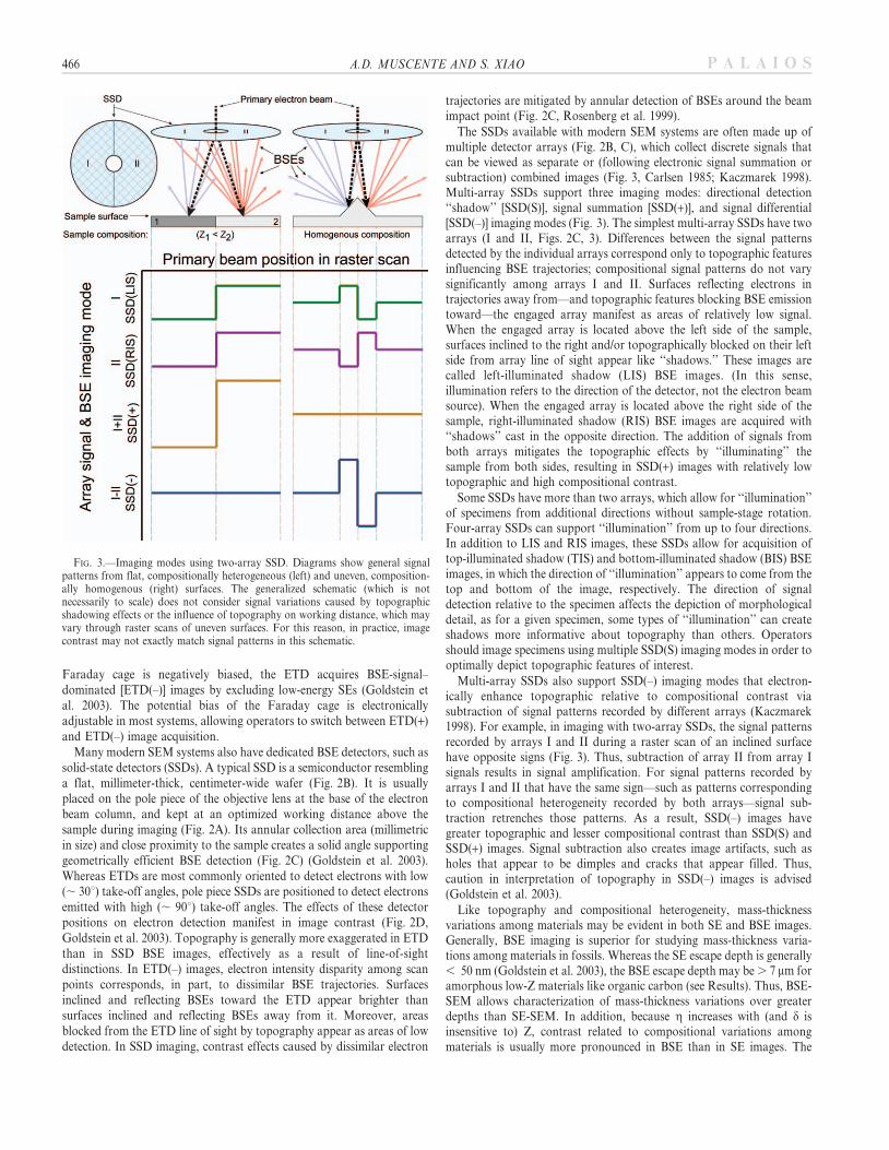
Combined light and electron microscopy affirms that Solite Quarryfossils are preserved as carbonaceous compressions with generally lowtopographic relief (Kearns and Orr 2009; Orr and Kearns 2011). Leafcompressions are evident in both ETD(+) and SSD(+) images(Fig. 4A–I), and SSD(+) images show that the carbonaceous materialmaking up leaf fossils is generally divided evenly between parts andcounterparts during rock splitting (Fig. 4B, C), although in somespecimens, the division is unequal (Fig. 5A–D). The BSE images typicallyresemble reflected light images in terms of morphological detail (Fig. 4A,B). However, some BSE images elucidate morphological features—particularly leaf veins—not readily apparent in reflected light images(Fig. 5A–E). In some places, the carbonaceous material is encrusted bysilicate minerals (Fig. 5F)—previously reported as biotite by Kearns andOrr (2009, fig. 3A) citing unpublished data—which appear brighter thanthe substrate in SSD(+) images. In EDS elemental maps, the encrustingsilicate minerals have higher iron and lower sodium concentrations thanthe substrate (Fig. 5G–R).
Beam energy image series demonstrate notable contrast change withVA. In images acquired at VA , 5 keV, contrast between the leaves andsubstrate is relatively high, and contrast between the leaf veins and leaflaminae is low (Figs. 4J, 5S). As VA increases from 5 to 15 keV, contrastincreases between leaf veins and leaf laminae, and decreases between leaflaminae and substrate (Figs. 4K, 5T, U). Imaging also reveals some leafveins that are not patently apparent at lower beam energies (Fig. 5T, U).In images acquired at VA . 15 keV, only the leaf veins are resolvable(Figs. 4K, 5U). As VA increases from 15 to 30 keV, contrast between theleaf veins and substrate decreases. Images acquired at 30 keV resolve noleaf tissues (Figs. 4L, 5V). The results did not vary between parts andcounterparts.
Analyses of insect compressions garnered similar results. Carbonaceousmaterial making up insect wing fossils is generally divided evenly amongparts and counterparts (Fig. 6A–F). Veins are the most patently apparentfeatures, and carbonaceous material between the veins may be theremnants of the insect wing membranes. In some places, the carbona-ceous material is encrusted by silicate minerals, which appear brighterthan the substrate in SSD(+) images (Fig. 6L–P). These silicate mineralswere not detected in EDS analyses, suggesting that they are too thin fordetection with EDS (Fig. 6G–K). As with the leaves, beam energy SSD(+)image series of the insect wings display notable changes in contrast withVA. In images acquired at low VA (, 2 keV), whereas the contrastbetween the fossil and the substrate is high, the contrast between theinsect wing veins and membranes is relatively low (Fig. 6L). The contrastbetween the insect wing veins and membranes increases with VA,revealing cross veins not patently apparent in reflected light images(Fig. 6M–O). However, in images acquired at VA . 12 keV, neither theveins nor membranes are evident (Fig. 6P).
468 A.D. MUSCENTE AND S. XIAO P A L A I O S
Imaging and Elemental Mapping of Sphenothallus
Electron imaging and EDS elemental mapping of Sphenothallus showthat the fossils are made up of discrete phosphate- and carbon-richlayers (Fig. 7A–O). In particular, SSD(+) images show high contrastbetween an exterior carbon-rich layer (ECL, , 1–3 mm thick) and anunderlying phosphorus-rich layer (PL, , 15–20 mm thick, Figs. 7G–I,8A–F). Imaging of shells with naturally exposed exterior-to-interiorcross sections shows that an interior carbon-rich layer (ICL, , 1–2 mm
thick) also covers the internal surface of the PL (Fig. 8G, T–Y). Allthese layers are evident in EDS elemental maps (Figs. 7J–O, 8H–Y).Imaging confirms that the PL consists of micrometer-thick phosphatic
lamellae (Fig. 7G), which are not evident in the ECL or ICL. The ECL
is covered by nanometer- to micrometer-sized holes (Fig. 7I), suggesting
it is made of porous material, similar to nanoporous organic matter
making up carbonaceous fossils (Schiffbauer et al. 2007; Schiffbauer
and Xiao 2009; Pang et al. 2013; Muscente et al. 2015). In some places,
FIG. 4.—Fernlike leaf from the Upper Triassic Cow Branch Formation at the Solite Quarry in Virginia. A) Reflected-light image of rachis (arrows) with three leaflets.B, C) Composite SSD(+) images of part and counterpart of leaflet surrounded by box in view A. D) Magnified SSD(+) image of boxed area in view B. Circles withnumbers indicate sizes and locations of point spectra in Table 2. E–H) EDS elemental maps of view D. I) An ETD(+) image of the boxed area in view D, showing lowtopographic relief of Solite Quarry compressions. J–L) Beam energy SSD(+) image series of boxed area in view D. M–P) Illustrative diagrams of views I–L.
BSE-SEM OF SUBSURFICIAL FOSSIL FEATURES 469P A L A I O S

470 A.D. MUSCENTE AND S. XIAO P A L A I O S

the ECL contains granular microstructures, which produce greater
signal than surrounding carbonaceous material (Figs. 8F, 9A–H).
Similar granular microstructures also occur in the PL (Fig. 9I–P).
Beam energy image series of ECLs and PLs containing microstructuresdemonstrate notable patterns of contrast change with VA (Figs. 9, 10).Granular microstructures occurring in the ECL are more numerous anddistinct in BSE images acquired at higher than at lower VA in the range of3–15 keV (Fig. 9A–D). The edges of some irregularly shaped micro-structures are evident on the surface of the ECL in ETD(+) images
(Fig. 9E), but many are only apparent in SSD(+) images (Fig. 9F–H).Similarly, although the PL microstructures are evident in SSD(+) imagesacquired at all beam energies (Fig. 9F–H), beam energy image series showthat granular microstructures also increase in abundance with VA
(Fig. 9I–P).
Evidently, Sphenothallus fossils at Heziao are preserved with greatertopographic relief than the Solite Quarry compressions. The Sphenothal-
lus fossils are covered by low-relief transverse ribs, which are evident inreflected light (Figs. 7P, Q, 10A), SE (Figs. 7V–X, 9R, 10B, C), and BSE
FIG. 6.—Insect wing from the Solite Quarry. A, B) Reflected light images of part and counterpart. C–F) Magnified reflected light (C, D) and ETD(+) images (E, F) ofboxed areas in views A and B. G–K) EDS elemental maps of view F. L–P) Beam energy SSD(+) image series of view F. Q–U) Illustrative diagrams of views L–P.
rFIG. 5.—Fernlike leaflet fossil (Wingatea?) from the Solite Quarry. A–D) Reflected-light (A, C) and composite SSD(+) images (B, D) of part (A, B) and counterpart (C,
D). E) Magnified image of boxed area in view B showing leaf veins not apparent in view A. F) Magnified image of boxed area in view D showing silicate minerals (brightershade of gray) encrusting carbonaceous leaf vein material (darker shade of gray). G–R) EDS elemental maps. Views G–L and M–R are maps of views E and F,respectively. S–V) Beam energy SSD(+) image series of boxed area in view E. Arrows in views T and U indicate vein not apparent at lower (view S) or higher (view V)beam energies. W–Z) Illustrative diagrams of views S–V.
BSE-SEM OF SUBSURFICIAL FOSSIL FEATURES 471P A L A I O S

472 A.D. MUSCENTE AND S. XIAO P A L A I O S

(Figs. 7R–U, 9Q, S, T, 10D–K) images of ECL surfaces. Contrast
between the topographic peaks and valleys of the transverse ribs (the
peak-valley contrast) is greater in 2 keV than in 20 keV ETD(+) images
(Fig. 7W, X), because d is typically highest at low beam energies (Reimer
and Tollkamp 1980). Thus, peak-valley contrast is greater in the BSE
images—particularly the ETD(–) and SSD(–) images (Fig. 7U, V)—than
in the ETD(+) images acquired at VA 20 keV (Fig. 7W). In terms of peak
contrast, the 20 keV BSE images closely resemble 2 keV ETD(+) images,
except these ETD(+) images resolve additional surface material covering
the transverse ribs (Fig. 7X). The transverse ribs are also evident in EDS
elemental maps (Figs. 9U–Z, 10L–U) due to differential X-ray emission
from peaks and valleys.
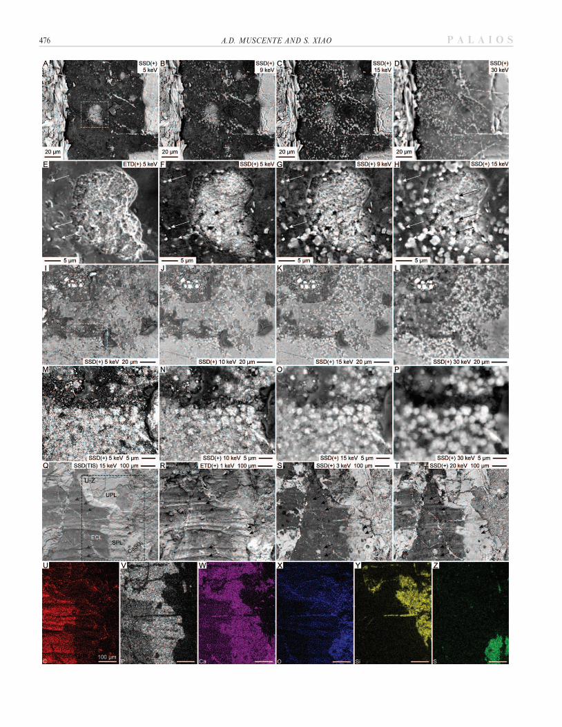
Transverse ribs are evident in SSD(+) images of ECL surfaces, but theirvisibility and appearance depends upon VA. In some specimens, thetransverse ribs are only evident in SSD(+) images acquired at VA . 10keV (Fig. 9T), but not at lower beam energies (Fig. 9S). In otherspecimens, the transverse ribs are resolvable in SSD(+) images acquired atall beam energies, but whereas the peaks generate greater signal than thevalleys at VA , 10 keV, the valleys generate greater signal than the peaksat higher beam energies (Fig. 10D–K).
External-to-internal cross sections through naturally brokenSphenothallus specimens show that the PL consists of exteriorsculptured PL (SPL) and interior unsculptured PL (UPL) lamellae(Fig. 9Q–T). Transverse ribs of Sphenothallus are evident in ETDand SSD(S)—but not SSD(+)—images of SPL without overlyingECL (Fig. 9Q–T). Images of exposed UPL resolve no evidenceof transverse ribs, regardless of detector, imaging mode, or VA (Fig. 9I–L, Q–T).
Monte Carlo Simulations
Monte Carlo simulations were conducted to model the interactionvolumes in three materials (bulk carbon, Solite Quarry shale, andSphenothallus PL) and three surface layer–substrate combinations(carbon on Solite Quarry shale, Sphenothallus ECL on PL, andSphenothallus PL on ICL and shale; Fig. 11). The compositions ofthe Solite Quarry shale and Sphenothallus PL were input into thesimulations as at% data, which were collected using EDS point spectraanalyses (Table 2), for elements present in the materials at . 1 at%.Density of the Solite Quarry shale (2.65 g/cm3) was estimated fromthe mass of shale pieces divided by their volume of water displacement.Density of the Sphenothallus PL (3.1 g/cm3) was estimated fromthe density of carbonate-rich apatite (francolite) minerals (Deer et al.2013).
Interaction volumes in carbonaceous layers were simulated in pure,homogenous carbon with the average density of kerogen (1.25 g/cm3) inthe early phase of petroleum generation (Okiongbo et al. 2005). In general,the density of carbonaceous material varies with maturity from , 1.18 g/cm3 in kerogen (Okiongbo et al. 2005) to 2.25 g/cm3 in graphite (vanKrevelen 1961). Rocks of the Solite Quarry have undergone low-grademetamorphosis to the zeolite facies (Ackermann et al. 2003), and it ispossible that the density of the carbonaceous material making up thecompressions may be greater than 1.25 g/cm3. If so, the Monte Carlosimulations may underestimate g and overestimate BSE escape depth with
respect to the Solite Quarry specimens, as g increases and BSE escapedepth decreases with density. Similarly, if the nanometer and micrometer-sized pores on the ECL surface indicate nano- or microporosity in the ECL,the Monte Carlo simulations may overestimate g and underestimate BSEescape depth with respect to the Sphenothallus specimens.
Monte Carlo simulations show that, for each material, the most commonand maximum BSE escape depths increase with VA, and for each beamenergy, are greater in carbon than in Solite Quarry shale or SphenothallusPL (Fig. 11A). The results of the simulations also show that g varies withVA and surface layer thickness for all surface layer–substrate combinations(Fig. 11B). For specimens with surface layer on a higher-Z substrate, atgiven VA, g is generally greater where the surface layer is thinner thanwhere it is thicker. Differences in g among scan points due to surface layerthickness disparity, however, are only detectable when the BSE escapedepth sufficiently exceeds the thickness of the surface layer. In addition,differences in g may not be detectable at higher beam energies, when theBSE escape depth greatly exceeds the thickness of the surface layer and thusbackscattering predominantly occurs from the substrate at all scan points.Overall, these observations are consistent with results of other studies (Orret al. 2002).
DISCUSSION
Mass-Thickness Contrast in Images of Solite Quarry Fossils
Because the illustrated Solite Quarry compressions have only minortopographic relief, the specimen properties most likely affecting contrastin the SSD(+) images of the fossils are compositional heterogeneity andmass-thickness variations among materials in the uppermost few micronsof the specimens. The effects of mass-thickness variations on g areevident in beam energy SSD(+) image series of leaves. In images acquiredat low VA (, 5 keV), the contrast between the leaves and substrate isrelatively high, and the contrast between the leaf veins and other leafblade tissues is relatively low (Figs. 4J–L, 5S–V). Through each beamenergy series, the leaf and substrate converge in signal, as expected fromMonte Carlo simulations, which show that the electron intensity at allscan points equals the substrate g at sufficiently high VA (Fig. 11). Thebeam energy image series also indicate that leaf veins converge on thesubstrate g at a higher VA than the other leaf blade tissues. As a result,leaf veins (but not leaf laminae) can be resolved in images acquired at VA
. 15 keV. This observation indicates the leaf veins are thicker than theleaf laminar tissues, as Monte Carlo simulations show that higher VA isrequired to penetrate thicker carbonaceous material before g isdominated by substrate material. Comparable trends are documented ininsect wing beam energy SSD(+) image series (Fig. 6L–U). In particular,the insect wing veins converge on the substrate g at a higher VA than theinsect wing membranes because they are preserved as thicker carbona-ceous films. Therefore, BSE imaging corroborates observations from X-ray microanalyses (Orr and Kearns 2011), indicating that soft tissues offossils in the Solite Quarry are preserved as carbon films of differentialthickness.
Carbonaceous compressions form through the collapse and concom-itant coalescence of multiple tissues (Rex and Chaloner 1983; Martı Mus2014), which involves diagenetic polymerization of biomacromoleculesinto long-chain aliphatic components (Stankiewicz et al. 2000). Therefore,
rFIG. 7.—Sphenothallus specimen with PL, ECL, and transverse ribs coated with , 20-nm-thick gold-palladium layer. A, B) Reflected-light and composite SSD(+)
images of specimen, respectively. C–F) EDS elemental maps of boxed area in view B. G, H) Magnified images of boxed areas in view B showing ECL and PL. Arrows inview G indicate foliation of phosphatic layer lamellae. I) Magnified image of boxed area in view H showing nanometer- and micrometer-sized holes on ECL surface. J–O)EDS elemental maps of view H. P, Q) Comparative reflected-light images of transverse ribs (boxed areas of A, B). R–U) SSD images of transverse ribs (boxed areasof A, B). V–X) ETD images of transverse ribs (boxed areas in views A, B). Illumination source is located toward the top in view P and the bottom in view Q.
BSE-SEM OF SUBSURFICIAL FOSSIL FEATURES 473P A L A I O S

FIG. 8.—Sphenothallus longitudinal thickening. A) Reflected light image. B) Composite SSD(+) image. C) Magnified image of boxed area in view B showing naturallyexposed exterior-to-interior cross section through shell with ECL, PL, and ICL exposed. D) Magnified image of boxed area in view B showing ECL encrusted by CaSO4
minerals and underlain by PL. E) Magnified image of boxed area in view B showing naturally exposed cross section through ECL and PL. Circles with numbers indicatesizes and locations of point spectra included in Table 2. F) Magnified image of view E showing microstructure (arrow) in ECL. G) Magnified image of boxed area in viewC showing PL and ICL. H–Y) EDS elemental maps. Views H–M, N–S, and T–Y are maps of views D, E, and the boxed area in G, respectively.
474 A.D. MUSCENTE AND S. XIAO P A L A I O S

the ultimate thickness of a carbonaceous film depends upon the totalthickness of the tissues prior to collapse and coalescence as well as theiroriginal composition, as some biomacromolecules are more degradationresistant and more likely to survive diagenesis than others (Tegelaar et al.1989; Briggs et al. 1999). For these reasons, thickness disparity amongleaf tissues in the Solite Quarry may correspond to the original 3-Danatomies of the leaves and/or original compositions of their tissues.Compared with spongy mesophyll tissues in leaf laminae, leaf veins aremade up of more densely packed cells, and they are often thicker than leaflaminae (Evert 2006). Hence, fossilized leaf veins may be thicker than leaflaminae because they were the densest and thickest parts of leaves in life.In addition, leaf vein xylem—the main conduit of water transport—consists of tracheid elements with primary and secondary walls contain-ing lignin (Evert 2006). Lignin is robust to degradation (Tegelaar et al.1989), and enhances the decay resistance of cellulose in plant cell walls(van Bergen et al. 1995). Thus, leaf veins may be preserved as thickercarbonaceous films than leaf laminae because they also originallycontained more lignin. Similar explanations may account for discrepan-cies among insect tissues in the Solite Quarry (Orr and Kearns 2011). Thepreservation potential of these tissues depends upon their degree ofsclerotization and original thickness (Briggs et al. 1999). Hence, the veinsmay be thicker carbonaceous films than the membranes of Solite Quarryinsect wings because they were originally thicker and more sclerotized.
Topographic and Mass-Thickness Contrast in Sphenothallus Images
Overall, electron images and EDS data corroborate other studies ofSphenothallus. Consistent with existing descriptions of the genus (van Itenet al. 1992), each tubular fossil from Heziao consists of a pair ofoppositely situated longitudinal thickenings, which branch near the apexand extend up to its aperture and are separated by two walls. Although itis uncertain whether Sphenothallus tests were originally phosphatic (vanIten et al. 1992), organic (Bodenbender et al. 1989), or organophosphatic(Li et al. 2004), the results of this study suggest that the tests consist ofdistinct organic and phosphatic layers (Fig. 8A–G) and that thephosphatic layers consist of carbon-rich apatite laminae (Fig. 7G,
Table 2). The new data substantiate other reports, including electronmicroscopy and EDS analyses that indicate Sphenothallus consists of
organic-associated (, 1 mm diameter) calcium phosphate laminae (Li etal. 2004), and unpublished SEM and X-ray diffraction data that suggest
Sphenothallus consists of cryptocrystalline carbonate-rich apatite (van
Iten et al. 1992).
This study also documents new Sphenothallus morphological char-acters. Electron images confirm that Sphenothallus specimens are coveredby low-relief transverse ribs (Fig. 7P–X), which have been reported but
not characterized in the literature (van Iten et al. 1992). Although thesetransverse ribs are evident in ETD and SSD images, peak-valley contrast
is generally greater in BSE images acquired using imaging modes
optimized for topographic contrast (Fig. 7S–V) than in ETD(+) images(Fig. 7W) acquired at VA . 5 keV. In terms of peak-valley contrast, the
BSE images (Fig. 7S–V) resemble ETD(+) images acquired at VA , 5 keV(Fig. 7X), although the ETD(+) images resolve additional surface
materials, which may obscure fossil morphology. Because BSEs emanate
from deeper within samples, these materials are not evident in SSD orETD(–) images.
Electron images and EDS elemental maps show that a typicalSphenothallus shell from the Heziao section of the Shuijingtuo Formation
consists of, from its internal to external surface, an ICL (Fig. 8G), UPL,SPL (Fig. 9Q), and ECL (Fig. 8E). The ECL and ICL (, 1–3 mm thick)
are either organic or less mineralized than the PL. The ECL and SPL
constitute the transverse ribs (Fig. 9Q–T). Transverse ribs are generallysinusoidal on ECL and exposed SPL surfaces (Figs. 7T–X, 9Q), but are
sometimes misshapen on ECL surfaces, having pointy peaks andshallowly concave valleys (Fig. 10C). Beam energy SSD(+) image series
of these transverse ribs resolve a notable change in peak-valley contrast
with VA. At low VA (,10 keV), the peaks appear brighter than the valleys(Fig. 10D–G). At higher VA (. 10 keV), the valleys appear brighter than
the peaks (Fig. 10H–K).
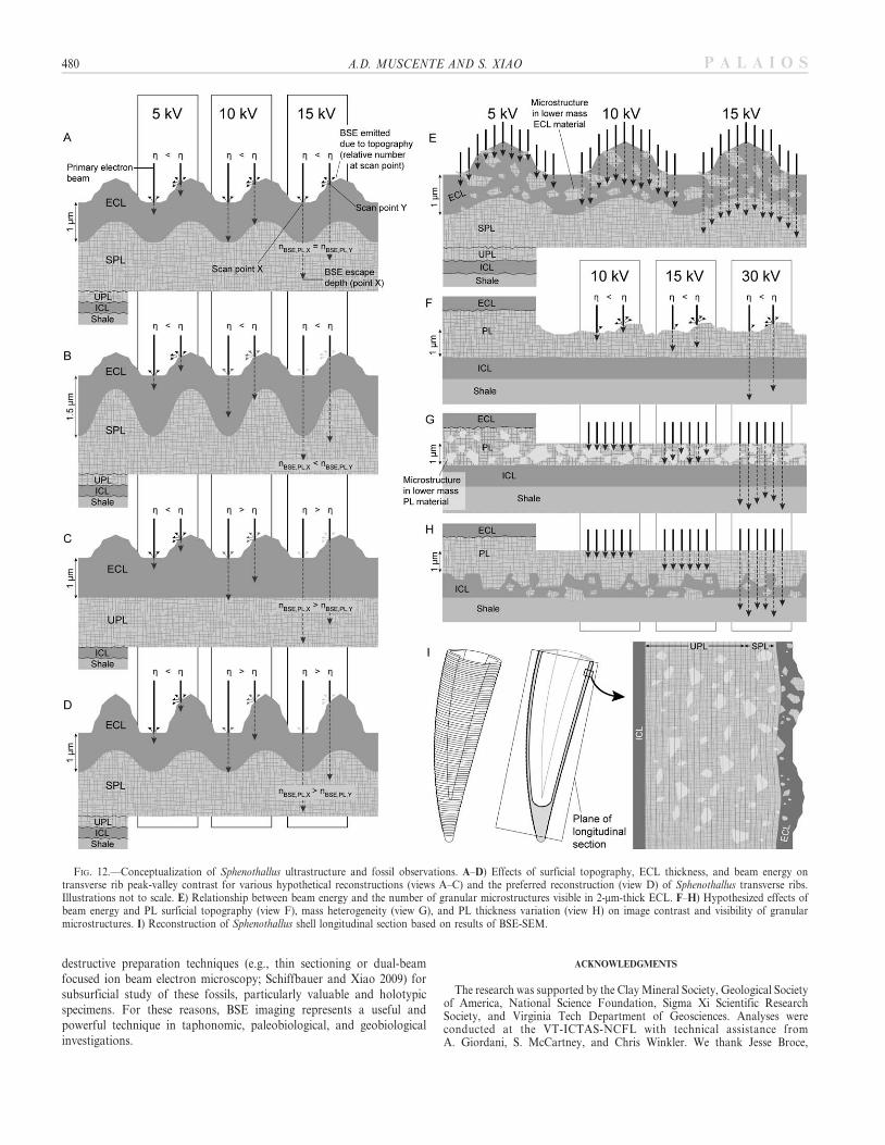
Comparisons of the peak-valley contrast predicted for severalhypothetical transverse rib reconstructions (Fig. 12A–D) at various beamenergies demonstrate that the observed change in peak-valley contrast
TABLE 2.—Elemental concentrations (in normalized atomic percent, at%) from EDS point spectra analyses of Solite Quarry substrate (SQS) hostingplant fossils and of phosphate-rich layer (PL) material making up Sphenothallus fossils. Averages, standard deviations, and values used to parameterize
Monte Carlo simulations are also included.
Fig., spot no. Material Al C Ca Fe In K Mg Na O P S Si Total
4D, 1 SQS 7.20 0 1.96 2.70 0 2.80 4.39 0 64.80 0 0 16.15 1004D, 2 SQS 6.46 0 1.63 2.91 0 2.68 5.09 2.55 62.35 0 0 16.33 1004D, 3 SQS 4.42 10.39 1.87 2.67 0 2.16 4.18 0 61.07 0 0 13.24 1004D, 4 SQS 7.36 3.66 0 2.40 0.60 1.45 4.67 0 62.56 0 0 17.30 1004D, 5 SQS 6.19 0 1.22 3.70 0 2.55 4.42 2.08 63.70 0 0 16.14 1004D, 6 SQS 6.89 0 1.68 2.48 0 2.33 4.77 0 66.60 0 0 15.25 1004D, 7 SQS 5.84 0 1.52 2.40 0 2.17 4.96 2.29 65.61 0 0 15.21 1004D, 8 SQS 5.59 13.46 1.37 2.42 0 1.76 3.22 0 58.32 0 0 13.86 100
Average 6.24 3.44 1.41 2.71 0.075 2.24 4.46 0.87 63.13 0 0 15.44Standard deviation 1.00 5.45 0.62 0.44 0.21 0.46 0.59 1.20 2.66 0 0 1.35
Values used in simulations 7 5 71 178E, 1 PL 0 31.63 11.34 0 0 0 0 0 52.20 3.68 0.40 0.75 1008E, 2 PL 0 31.86 11.48 0 0 0 0 0 50.80 4.43 0.43 1.00 1008E, 3 PL 0.50 37.95 13.58 0 0 0 0 0 38.61 6.79 0.65 1.92 1008E, 4 PL 0 32.65 14.04 0 0 0 0 0 45.61 6.01 0.41 1.28 1008E, 5 PL 0 32.14 13.56 0 0 0 0 0 47.58 5.43 0.48 0.81 1008E, 6 PL 0 31.76 12.01 0 0 0 0 0 49.67 5.11 0.33 1.12 1008E, 7 PL 0 37.46 7.56 0 0 0 0 0 49.65 4.06 0.47 0.80 1008E, 8 PL 0.46 34.80 12.80 0 0 0 0 0 44.42 4.81 0.51 2.20 100
Average 0.12 33.78 12.05 0 0 0 0 0 47.32 5.04 0.46 1.24Standard deviation 0.22 2.63 2.07 0 0 0 0 0 4.38 1.03 0.09 0.54
Values used in simulations 34 12 48 6
BSE-SEM OF SUBSURFICIAL FOSSIL FEATURES 475P A L A I O S
476 A.D. MUSCENTE AND S. XIAO P A L A I O S

with VA is related to transverse rib topography and ECL thicknessvariation. The hypothetical reconstructions, in toto, presume that theECL constituting the transverse ribs is either uniformly thick (Fig. 12A),thicker in the valleys (Fig. 12B), or thicker on the peaks (Fig. 12C, D).For all these hypothetical reconstructions, it is predicted that at low beamenergies (,10 keV)—when the BSE escape depth is less than ECLthickness—the shallowly concave valleys should backscatter fewerelectrons than the slopes making up the peaks of the transverse ribs, ashC and consequently g is greatest on the slopes. Contrarily, predictions ofpeak-valley contrast in images acquired at higher beam energies—whenelectrons are backscattered from both the ECL and PL—vary amonghypothetical reconstructions; scan points where the ECL is thinner andrelatively more electrons are backscattered from the PL may appearbrighter than scan points where the ECL is thicker. Monte Carlosimulations affirm the plausibility of these predictions, showing thatbackscattering may occur from a PL beneath a . 1-mm-thick ECL at VA
. 10 keV (Fig. 11A). These predictions indicate that valleys shouldbackscatter more electrons and appear brighter than the peaks if (1) theECL is thinner in the valleys (, 1 mm thick) than on the peaks and (2) theBSE escape depth exceeds the thickness of the ECL in the valley(Figs. 12C, D). Based on these predictions, the change in peak-valleycontrast observed in beam energy SSD(+) image series of transverse ribs(Fig. 10D–K), and the observation that both the ECL and SPL constitutethe transverse ribs (Fig. 9Q–T), the preferred transverse rib reconstruc-tion (Fig. 12D) has SPL overlain by ECL, which is thinner in the valleysthan on the peaks.
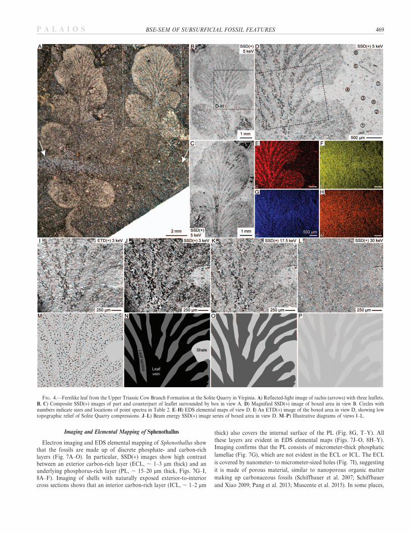
The ECL contains granular microstructures in some places. Althoughsurface-sensitive ETD(+) images show that the edges of some irregularlyshaped microstructures are exposed on the ECL surface (Fig. 9E), manymicrostructures apparent in SSD(+) images of ECL surfaces do notcorrespond to features in ETD(+) images. Therefore, some granularmicrostructures are located beneath the ECL surface, and mass-thicknessvariations between the granular microstructure and surrounding ECLmaterials (rather than topography) are the source of contrast. Thecontrast may indicate that the granular microstructures are composition-ally distinct from surrounding ECL material, for instance, because theyare phosphatic. Alternatively, granular microstructures may be moredense (and backscatter more electrons) than surrounding ECLmaterial. The abundance of ECL granular microstructures in SSD(+)images increases with VA between 5 and 15 keV (Fig. 9A–H), as thenumber of granular microstructures within the ECL able to interactwith and backscatter beam electrons increases with VA (Fig. 12E).From 15–30 keV, the abundance of microstructures does not change,and contrast between the ECL and the exposed PL decreases when VA
increases from 15 to 30 keV (Fig. 9C, D), probably reflectingbackscattering from the PL substrate at all scan points. Monte Carlosimulations indicate that, for 2-mm-thick ECL, backscattering occursfrom substrates at VA . 15 keV.
Granular microstructures are also apparent in BSE images of the PL(Fig. 9I–P). The granular microstructures are apparent at 5 keV in BSEimages of PL that is . 1 mm thick (Fig. 9F). Because the PL is . 1 mmthick and Monte Carlo simulations indicate backscattering only occursfrom the substrate beneath 1-mm-thick PL at .15 keV (Fig. 11A), it is
unlikely that the granules lie beneath an intact PL. Rather, the granularmicrostructures apparent at 5 keV are most likely the manifestation ofPL topography (Fig. 12F) and/or mass heterogeneity of the PLcontaining granules (Fig. 12G). The topography may reflect ECLgranules attached to the PL after the ECL has been exfoliated (e.g.,Fig. 9H), though SE images do not show topography corresponding togranules (Fig. 9E). Of course, it is possible that, if the SPL and upperUPL lamellae have been exfoliated and the exposed PL is ,1 mm thick,the scenario depicted in Fig. 12H could explain the observation ofgranules at low VA and their increasing abundance with VA.
Integration of the observations of Sphenothallus yields a new longitu-dinal cross-sectional reconstruction of the problematic shelly fossil(Fig. 12I). The test of Sphenothallus consists of several layers, includingthe ICL, UPL, SPL, and ECL. Granular microstructures of higherdensity or higher Z than surrounding material are present in at least theECL and PL. The SPL and ECL constitute the transverse ribs on thefossils. In some specimens, the ECL is thicker on the peaks than in thevalleys of the transverse ribs. This reconstruction has implications forSphenothallus affinities. Some interpretations favor the placement ofSphenothallus among conulariids (van Iten et al. 1992), and indeed, thenew reconstruction affirms that the tests of both groups consist of outerphosphatic layers with transverse ribs and inner phosphatic layers withsmooth phosphatic lamellae (Van Iten 1992). However, no layersanalogous to the Sphenothallus ECL or ICL have been reported fromconulariids, and no granular microstructures occur in conulariidphosphatic layers. Further study is needed to determine the significanceof these features.
CONCLUSIONS
In summary, we have demonstrated that BSE imaging presentsopportunities to resolve 3-D surficial topographies and subsurficialmicrostructures of fossils, with advantages over other characterizationtechniques. Imaging with BSEs provides the key benefits of electron overlight microscopy—particularly improved resolution and magnification—but does not require coating nonconductive and insulating specimenswith conductive carbon or gold-palladium layers, as is commonly neededto reduce surface charging during SE imaging. With detectors anddetector configurations optimized for topographic contrast, such as lowtake-off angle BSE detectors and multi-array angular BSE detectors,BSE-SEM can generate images comparable to SE images in terms oftopographic detail. When specimen topography is low relief or concealedby surficial material, BSE imaging can also resolve features not patentlyapparent in reflected light microscopy or SE images. In addition, becauseBSEs emanate from several micrometers below sample surfaces, BSEimaging can elucidate subsurficial microstructures invisible in light or SEmicroscopy, and can produce beam energy image series analogous totomographic datasets. Subsurficial imaging with BSEs generally does notexceed 5 mm in depth, except in low-density materials like amorphousorganic carbon. Nonetheless, many types of fossils—including carbona-ceous compressions, organically preserved microfossils, and shellyfossils—have amorphous organic carbon layers that are micrometers inthickness. Hence, BSE imaging provides a valuable alternative to
rFIG. 9.—Granular microstructures in Sphenothallus ECL and PL. A–D) Beam energy SSD(+) image series of boxed area in Figure 8D, showing increase in number of
ECL microstructures with VA. E) Magnified ETD(+) and F–H) SSD(+) images of boxed area in view A, showing edges of irregularly shaped granular microstructures(indicated by white arrows) located at or near the ECL surface. Black arrows in view H indicate granular microstructures in PL. I–L) Beam energy SSD(+) image series ofFigure 8G, showing increase in number of PL granular microstructures with VA. M–P) Beam energy image SSD(+) image series of boxed area in view I, showing granularmicrostructure in , 1-mm-thick PL, where the SPL and upper UPL lamellae have been exfoliated. Q) Comparative SSD(TIS), R) ETD(+), and S, T) SSD(+) images ofboxed area in Figure 8B, showing ECL, SPL, and UPL. Arrows indicate topographic peaks of transverse ribs. U–Z) EDS elemental maps of boxed area in view Q.
BSE-SEM OF SUBSURFICIAL FOSSIL FEATURES 477P A L A I O S

478 A.D. MUSCENTE AND S. XIAO P A L A I O S

rFIG. 10.—Systematic imaging of Sphenothallus transverse ribs. A) Reflected-light image. B) ETD(+) image. C) Magnified ETD(+) image of boxed area in view B,
showing surficial topography of transverse ribs. D–K) Beam energy SSD(+) image series of view C. For comparisons among views C–K, the corresponding locations ofthree rib peaks a, b, and c are labeled. Lines indicate the approximate widths of the peaks. L–P) EDS elemental maps of view B. Q–U) EDS elemental maps of boxed areain view C.
FIG. 11.—Results of Monte Carlo simulations. A) Graphs illustrating increase in BSE escape depth with beam energy for materials in this study. Each color (keylocated below view A) represents a set of 200,000 interaction volumes simulated in a material at a given beam energy, and each data point indicates the proportion of BSEtrajectories in the simulation set and their greatest depth in the sample before escaping the surface, reported for 2500 depth values between 0 mm and maximum escapedepth recorded at the given VA. B) Graphs illustrating relationships between g and VA for the surface layer–substrate combinations in this study. CL 5 carbon layer; PL5 phosphorus-rich layer.
BSE-SEM OF SUBSURFICIAL FOSSIL FEATURES 479P A L A I O S
destructive preparation techniques (e.g., thin sectioning or dual-beamfocused ion beam electron microscopy; Schiffbauer and Xiao 2009) forsubsurficial study of these fossils, particularly valuable and holotypicspecimens. For these reasons, BSE imaging represents a useful andpowerful technique in taphonomic, paleobiological, and geobiologicalinvestigations.
ACKNOWLEDGMENTS
The research was supported by the Clay Mineral Society, Geological Societyof America, National Science Foundation, Sigma Xi Scientific ResearchSociety, and Virginia Tech Department of Geosciences. Analyses wereconducted at the VT-ICTAS-NCFL with technical assistance fromA. Giordani, S. McCartney, and Chris Winkler. We thank Jesse Broce,
FIG. 12.—Conceptualization of Sphenothallus ultrastructure and fossil observations. A–D) Effects of surficial topography, ECL thickness, and beam energy ontransverse rib peak-valley contrast for various hypothetical reconstructions (views A–C) and the preferred reconstruction (view D) of Sphenothallus transverse ribs.Illustrations not to scale. E) Relationship between beam energy and the number of granular microstructures visible in 2-mm-thick ECL. F–H) Hypothesized effects ofbeam energy and PL surficial topography (view F), mass heterogeneity (view G), and PL thickness variation (view H) on image contrast and visibility of granularmicrostructures. I) Reconstruction of Sphenothallus shell longitudinal section based on results of BSE-SEM.
480 A.D. MUSCENTE AND S. XIAO P A L A I O S
Drew Hawkins, Mike Meyer, Michael Nakagaki, Ken O’Donnell, andQing Tang for assistance in Sphenothallus collection, and Jim Beardfor discussion of the Solite Quarry material. We additionally thankJim Schiffbauer, a PALAIOS associate editor, and two anonymousreviewers for critical comments that greatly improved the quality of this report.
REFERENCES
ACKERMANN, R.V., SCHLISCHE, R.W., PATINO, L.C., AND JOHNSON, L.A., 2003, ALagerstatte of rift-related tectonic structures from the Solite Quarry, Dan River/Danville rift basin, in LeTourneau, P.M., and Olsen, P.E., eds., The Great Rift Valleysof Pangea: New York City, Columbia University Press, p. 118–133.
BODENBENDER, B.E., WILSON, M.A., AND PALMER, T.J., 1989, Paleoecology ofSphenothallus on an Upper Ordovician hardground: Lethaia, v. 22, p. 217–225.
BRIGGS, D.E.G., CHALONER, W.G., AMBLER, R.P., MACKO, S., BADA, J., AND HUBBARD,J., 1999, Molecular taphonomy of animal and plant cuticles: selective preservationand diagenesis [and discussion]: Royal Society of London, Philosophical Transac-tions: Biological Sciences, v. 354, p. 7–17.
CARLSEN, I.C., 1985, Reconstruction of true surface-topographies in scanning electronmicroscopes using backscattered electrons: Scanning, v. 7, p. 169–177.
DEER, W.A., HOWIE, R.A., AND ZUSSMAN, J., 2013, An introduction to the rock-formingminerals, 3rd ed.: London, The Mineralogical Society, 498 p.
DING, Z.J., AND LI, H.M., 2005, Application of Monte Carlo simulation toSEM image contrast of complex structures: Surface and Interface Analysis, v. 37, p.912–918.
DROUIN, D., COUTURE, A.R., JOLY, D., TASTET, X., AIMEZ, V., AND GAUVIN, R., 2007,CASINO V2.42: a fast and easy-to-use modeling tool for scanning electronmicroscopy and microanalysis users: Scanning, v. 29, p. 92–101.
EVERHART, T.E., AND THORNLEY, R.F.M., 1960, Wide-band detector for micro-microampere low-energy electron currents: Journal of Scientific Instruments, v. 37,p. 246.
EVERT, R.F., 2006, Esau’s Plant Anatomy: Hoboken, John Wiley and Sons, Inc., 601 p.FRASER, N.C., GRIMALDI, D.A., OLSEN, P.E., AND AXSMITH, B., 1996, A Triassic
Lagerstatte from eastern North America: Nature, v. 380, p. 615–619.GIGNAC, L.M., KAWASAKI, M., BOETTCHER, S.H., AND WELLS, O.C., 2005, Imaging and
analysis of subsurface Cu interconnects by detecting backscattered electrons in thescanning electron microscope: Journal of Applied Physics, v. 97, p. 1–9.
GOLDSTEIN, J., NEWBURY, D.E., ECHLIN, P., JOY, D.C., LYMAN, C.E., LIFSHIN, E.,SAWYER, L., AND MICHAEL, J.R., 2003, Scanning Electron Microscopy and X-RayMicroanalysis, 3rd ed.: New York City, Springer U.S., 689 p.
GOSTEV, A.V., DITSMAN, S.A., LUK’YANOV, F.A., ORLIKOVSKII, N.A., RAU, E.I., AND
SENNOV, R.A., 2010, A method and devices of electron microtomography in scanningelectron microscopy: Instruments and Experimental Techniques, v. 53, p. 581–590.
KACZMAREK, D., 1998, Backscattered electrons topographic mode problems in thescanning electron microscope: Scanning Microscopy, v. 12, p. 161–169.
KEARNS, S.L., AND ORR, P.J., 2009, Charge contrast imaging of exceptionally-preservedfossils: Palaeontology, v. 52, p. 673–680.
LEE, M.R., AND SMITH, C.L., 2006, Scanning transmission electron microscopy usinga SEM: Applications to mineralogy and petrology: Mineralogical Magazine, v. 70, p.579–590.
LI, G.-X., ZHU, M.-Y., VAN ITEN, H., AND LI, C.-W., 2004, Occurrence of the earliestknown Sphenothallus Hall in the lower Cambrian of Southern Shaanxi Province,China: Geobios, v. 37, p. 229–237.
LIUTKUS, C.M., BEARD, J.S., FRASER, N.C., AND RAGLAND, P.C., 2010, Use of fine-scalestratigraphy and chemostratigraphy to evaluate conditions of deposition andpreservation of a Triassic Lagerstatte, south-central Virginia: Journal of Paleolimnol-ogy, v. 44, p. 645–666.
LLOYD, G.E., 1987, Atomic number and crystallographic contrast images with the SEM:a review of backscattered electron techniques: Mineralogical Magazine, v. 51, p. 3–19.
MARTı MUS, M., 2014, Interpreting ‘‘shelly’’ fossils preserved as organic films: the caseof hyolithids: Lethaia, v. 47, p. 397–404.
MERLI, P.G., MORANDI, V., AND CORTICELLI, F., 2003, Backscattered electron imagingand scanning transmission electron microscopy imaging of multi-layers: Ultramicro-scopy, v. 94, p. 89–98.
MUSCENTE, A.D., MICHEL, F.M., DALE, J., AND XIAO, S., 2015, Assessing the veracity ofPrecambrian ‘‘sponge’’ fossils using in situ nanoscale analytical techniques:Precambrian Research, v. 263, p. 142–156.
NIEDRIG, H., 1982, Electron backscattering from thin films: Journal of Applied Physics,v. 53, p. R15–R49.
NIEDRIG, H., AND RAU, E.I., 1998, Information depth and spatial resolution in BSEmicrotomography in SEM: Nuclear Instruments and Methods in Physics ResearchSection B: Beam Interactions with Materials and Atoms, v. 142, p. 523–534.
OKIONGBO, K.S., APLIN, A.C., AND LARTER, S.R., 2005, Changes in type II kerogendensity as a function of maturity: Evidence from the Kimmeridge Clay Formation:Energy and Fuels, v. 19, p. 2495–2499.
ORR, P.J., AND KEARNS, S.L., 2011, X-ray microanalysis of Burgess Shale and similarlypreserved fossils: numerical approaches to the evaluation of fossils and ancientecosystems, in Laflamme, M., Schiffbauer, J.D., and Dornbos, S.Q., eds., Quantifyingthe Evolution of Early Life: New York City, Springer Netherlands, p. 271–297.
ORR, P.J., KEARNS, S.L., AND BRIGGS, D.G., 2002, Backscattered electronimaging of fossils exceptionally-preserved as organic compressions: PALAIOS, v.17, p. 110–117.
ORR, P.J., KEARNS, S.L., AND BRIGGS, D.E.G., 2009, Elemental mapping of exceptionallypreserved ‘‘carbonaceous compression’’ fossils: Palaeogeography, Palaeoclimatology,Palaeoecology, v. 277, p. 1–8.
PANG, K., TANG, Q., SCHIFFBAUER, J.D., YAO, J., YUAN, X., WAN, B., CHEN, L., OU, Z.,AND XIAO, S., 2013, The nature and origin of nucleus-like intracellular inclusions inPaleoproterozoic eukaryote microfossils: Geobiology, v. 11, p. 499–510.
PRIOR, D.J., BOYLE, A.P., BRENKER, F., CHEADLE, M.C., DAY, A., LOPEZ, G., PERUZZO,L., POTTS, G.J., REDDY, S., AND SPIESS, R., 1999, The application of electronbackscatter diffraction and orientation contrast imaging in the SEM to texturalproblems in rocks: American Mineralogist, v. 84, p. 1741–1759.
PYE, K., AND KRINSLEY, D.H., 1984, Petrographic examination of sedimentary rocks inthe SEM using backscattered electron detectors: Journal of Sedimentary Research, v.54, p. 877–888.
REIMER, L., AND KOHL, H., 2008, Transmission Electron Microscopy: Physics of ImageFormation: New York City, Springer-Verlag New York, 590 p.
REIMER, L., AND TOLLKAMP, C., 1980, Measuring the backscattering coefficient andsecondary electron yield inside a scanning electron microscope: Scanning, v. 3, p. 35–39.
REX, G.M., AND CHALONER, W.G., 1983, The experimental formation of plantcompression fossils: Palaeontology, v. 26, p. 231–252.
ROSENBERG, N., JIANG, C.Z., AND MORIN, P., 1999, Monte Carlo simulations of coaxialbackscattered electrons in SEM: Ultramicroscopy, v. 76, p. 97–105.
SAKAI, Y., YAMADA, T., SUZUKI, T., AND ICHINOKAWA, T., 1999, Contrast mechanisms ofsecondary electron images in scanning electron and ion microscopy: Applied SurfaceScience, v. 144–145, p. 96–100.
SCHIFFBAUER, J.D., AND XIAO, S., 2009, Novel application of focused ion beam electronmicroscopy (FIB-EM) in the preparation and analysis of microfossil ultrastructures:PALAIOS, v. 24, p. 616–626.
SCHIFFBAUER, J.D., YIN, L., BODNAR, R.J., KAUFMAN, A.J., MENG, F., HU, J., SHEN, B.,YUAN, X., BAO, H., AND XIAO, S., 2007, Ultrastructural and geochemicalcharacterization of Archean–Paleoproterozoic graphite particles: implications forrecognizing traces of life in highly metamorphosed rocks: Astrobiology, v. 7, p. 684–704.
SCHIFFBAUER, J.D., XIAO, S., SEN SHARMA, K., AND WANG, G., 2012, The originof intracellular structures in Ediacaran metazoan embryos: Geology, v. 40,p. 223–226.
SHIMIZU, R., IKUTA, T., AND MURATA, K., 1972, The Monte Carlo technique as appliedto the fundamentals of EPMA and SEM: Journal of Applied Physics, v. 43, p. 4233–4249.
STANKIEWICZ, B.A., BRIGGS, D.E.G., MICHELS, R., COLLINSON, M.E., FLANNERY, M.B.,AND EVERSHED, R.P., 2000, Alternative origin of aliphatic polymer in kerogen:Geology, v. 28, p. 559–562.
TAYLOR, P.D., 1986, Scanning electron microscopy of uncoated fossils: Palaeontology,v. 29, p. 685–690.
TEGELAAR, E.W., DE LEEUW, J.W., DERENNE, S., AND LARGEAU, C., 1989, A reappraisalof kerogen formation: Geochimica et Cosmochimica Acta, v. 53, p. 3103–3106.
VAN BERGEN, P.F., COLLINSON, M.E., BRIGGS, D.E.G., DE LEEUW, J.W., SCOTT, A.C.,EVERSHED, R.P., AND FINCH, P., 1995, Resistant biomacromolecules in the fossilrecord: Acta Botanica Neerlandica, v. 44, no. 4, p. 319–342.
VAN ITEN, H., 1992, Microstructure and growth of the conulariid test: implications forconulariid affinities: Palaeontology, v. 35, p. 359–372.
VAN ITEN, H., COX, R.S., AND MAPES, R.H., 1992, New data on the morphologyof Sphenothallus Hall: implications for its affinities: Lethaia, v. 25, p. 135–144.
VAN KREVELEN, D.W., 1961, Coal: Typology, Chemistry, Physics, Constitution:Amsterdam, Elsevier, 514 p.
Received 28 October 2014; accepted 9 March 2015.
BSE-SEM OF SUBSURFICIAL FOSSIL FEATURES 481P A L A I O S