Research on the Intelligent Construction of the Rebar Project ...
19
Citation: Wang, D.; Hu, Y. Research on the Intelligent Construction of the Rebar Project Based on BIM. Appl. Sci. 2022, 12, 5596. https://doi.org/ 10.3390/app12115596 Academic Editor: Muhammad Junaid Munir Received: 18 May 2022 Accepted: 30 May 2022 Published: 31 May 2022 Publisher’s Note: MDPI stays neutral with regard to jurisdictional claims in published maps and institutional affil- iations. Copyright: © 2022 by the authors. Licensee MDPI, Basel, Switzerland. This article is an open access article distributed under the terms and conditions of the Creative Commons Attribution (CC BY) license (https:// creativecommons.org/licenses/by/ 4.0/). applied sciences Article Research on the Intelligent Construction of the Rebar Project Based on BIM Dejiang Wang * and Youyang Hu Department of Civil Engineering, Shanghai University, Shanghai 200444, China; [email protected] * Correspondence: [email protected] Abstract: Rebar engineering in the construction industry lacks effective technical means and has a high processing cost and high waste rate. Under the background of intelligent construction, the centralized processing mode of steel bars in prefabricated factories realizes the automatic processing of steel bars and improves the processing efficiency of steel bars. Using the C# programming language, combined with Revit secondary development technology, the automatic generation of the rebar model and the automatic export of rebar drawing are realized, which saves time for the designers to build the model. The calculation method of the cutting length of the steel bar is analyzed in this paper, which can be used as a reference for the subsequent optimization research of steel bar cutting. The assembly position information of the steel bar was introduced into an Excel table to help realize the automatic assembly of the steel bar cage and the intelligent construction of the steel bar. Combined with mixed reality technology, project personnel can interact with the reinforced BIM model through the mixed reality device Hololens2 to guide construction remotely. Keywords: building information modelling; BIM application; rebar project; intelligent construction; mixed reality 1. Introduction With the continuous development of information technology, especially the deepening of the application of BIM technology, it is possible to realize the application of informati- zation in the steel bar construction process with low standardization, complex type and specification information, high process connection requirements, and limited operator quality. It will effectively promote the improvement, transformation, and upgrading of the professional management level of steel bars [1,2]. Intelligent construction has been used in various fields of construction engineering, such as the development of building management systems, the application of smart construction sites, and the construction of smart stadiums [3–5]. Intelligent construction can realize the use of programs to extract the location information of the rebar in the BIM model of the column, and use the rebar installation robot to install the rebar according to the specific location of the rebar, which greatly reduces the labor cost and solves the problem of irregular rebar installation. The staff can stay away from arc light and metal spatter during the welding process, and only need to perform welding inspection at a distance. The rebar installation robot can auto- matically weld several sections of the rebar in place efficiently and accurately, avoiding the possible harm to workers caused by molten metal. Especially in high temperature weather, the labor intensity of front-line workers is greatly reduced, and the project progress is accelerated [6–8]. Moreover, the welding accuracy is higher than that of manual work, the welding consistency is good, and the welding quality is stable and reliable. This whole process can directly produce steel bar raw materials into finished steel bar cages, which solves various problems caused by the fast construction progress of the project, the large demand for components, and the limited storage space on the construction site [9–11]. At present, BIM technology has been widely used in the field of public civil buildings and municipal areas, and many scholars have conducted research on BIM technology in Appl. Sci. 2022, 12, 5596. https://doi.org/10.3390/app12115596 https://www.mdpi.com/journal/applsci
-
Upload
khangminh22 -
Category
Documents
-
view
1 -
download
0
Transcript of Research on the Intelligent Construction of the Rebar Project ...

Citation: Wang, D.; Hu, Y. Research
on the Intelligent Construction of the
Rebar Project Based on BIM. Appl. Sci.
2022, 12, 5596. https://doi.org/
10.3390/app12115596
Academic Editor: Muhammad
Junaid Munir
Received: 18 May 2022
Accepted: 30 May 2022
Published: 31 May 2022
Publisher’s Note: MDPI stays neutral
with regard to jurisdictional claims in
published maps and institutional affil-
iations.
Copyright: © 2022 by the authors.
Licensee MDPI, Basel, Switzerland.
This article is an open access article
distributed under the terms and
conditions of the Creative Commons
Attribution (CC BY) license (https://
creativecommons.org/licenses/by/
4.0/).
applied sciences
Article
Research on the Intelligent Construction of the Rebar ProjectBased on BIMDejiang Wang * and Youyang Hu
Department of Civil Engineering, Shanghai University, Shanghai 200444, China; [email protected]* Correspondence: [email protected]
Abstract: Rebar engineering in the construction industry lacks effective technical means and hasa high processing cost and high waste rate. Under the background of intelligent construction, thecentralized processing mode of steel bars in prefabricated factories realizes the automatic processingof steel bars and improves the processing efficiency of steel bars. Using the C# programming language,combined with Revit secondary development technology, the automatic generation of the rebar modeland the automatic export of rebar drawing are realized, which saves time for the designers to buildthe model. The calculation method of the cutting length of the steel bar is analyzed in this paper,which can be used as a reference for the subsequent optimization research of steel bar cutting. Theassembly position information of the steel bar was introduced into an Excel table to help realize theautomatic assembly of the steel bar cage and the intelligent construction of the steel bar. Combinedwith mixed reality technology, project personnel can interact with the reinforced BIM model throughthe mixed reality device Hololens2 to guide construction remotely.
Keywords: building information modelling; BIM application; rebar project; intelligent construction;mixed reality
1. Introduction
With the continuous development of information technology, especially the deepeningof the application of BIM technology, it is possible to realize the application of informati-zation in the steel bar construction process with low standardization, complex type andspecification information, high process connection requirements, and limited operatorquality. It will effectively promote the improvement, transformation, and upgrading ofthe professional management level of steel bars [1,2]. Intelligent construction has beenused in various fields of construction engineering, such as the development of buildingmanagement systems, the application of smart construction sites, and the construction ofsmart stadiums [3–5]. Intelligent construction can realize the use of programs to extractthe location information of the rebar in the BIM model of the column, and use the rebarinstallation robot to install the rebar according to the specific location of the rebar, whichgreatly reduces the labor cost and solves the problem of irregular rebar installation. Thestaff can stay away from arc light and metal spatter during the welding process, and onlyneed to perform welding inspection at a distance. The rebar installation robot can auto-matically weld several sections of the rebar in place efficiently and accurately, avoiding thepossible harm to workers caused by molten metal. Especially in high temperature weather,the labor intensity of front-line workers is greatly reduced, and the project progress isaccelerated [6–8]. Moreover, the welding accuracy is higher than that of manual work, thewelding consistency is good, and the welding quality is stable and reliable. This wholeprocess can directly produce steel bar raw materials into finished steel bar cages, whichsolves various problems caused by the fast construction progress of the project, the largedemand for components, and the limited storage space on the construction site [9–11].
At present, BIM technology has been widely used in the field of public civil buildingsand municipal areas, and many scholars have conducted research on BIM technology in
Appl. Sci. 2022, 12, 5596. https://doi.org/10.3390/app12115596 https://www.mdpi.com/journal/applsci

Appl. Sci. 2022, 12, 5596 2 of 19
various fields. F Troncoso-Pastoriza [12] introduced an automatic monitoring methodfor the lighting elements of buildings; R Bortolini [13] introduced the application of BIMtechnology in the field of prefabricated buildings; E Kamel [14] described the use of BIMin energy simulation for the application of BIM; and G Yilmaz [15] developed severalreference models to evaluate the engineering efficiency improved by BIM in the buildingconstruction process. A Basta [16] proposed a method to evaluate the deconstruction abilityof steel structures based on BIM.
The research in this paper is mainly based on Revit. The use of Revit software in thefield of construction engineering, combined with other software, can run through the entireproject life cycle from the early conceptual design, mid-term visualization [17], and forceanalysis to post-construction, improving the efficiency and accuracy of project construc-tion [18]. In the early conceptual design stage, Revit and Insight can be used in combination;Insight can be used to analyze the energy consumption of the model, and explore moreenergy-efficient design concepts. Revit is combined with Formlt software for preliminarycollaborative designs; preliminary design and sketch modeling can be carried out in Formlt,and then the design can be directly sent to Revit for subsequent detailed design. After thedesign is completed, the Robot Structural Analysis Professional finite element structuralanalysis software can be used to perform structural stress analysis on the concrete andsteel structures in the Revit model to verify the rationality of the structural design. Beforethe start of the construction phase, Navisworks can be used to check the collision of theRevit model, carry out construction simulation, predict various problems that may occurin the construction process in advance, and eliminate the hidden engineering problemsoften encountered by the owner in the design and construction phases [19–21]. Overall,Autodesk’s suite of software for architectural engineering enables high-quality and high-performance architectural design, optimizing projects using integrated analysis, generativedesign, and visualization and simulation tools. It can maximize the constructability andcoordination of the project, and improve the predictability during the construction processof the project site.
Mixed reality technology (Mixed Reality, MR) refers to a new way of visualizing thesurrounding environment generated by the combination of the real world and virtual digitalworld [22]. The concept of mixed reality was first proposed by the Canadian Paul Milgramand Japanese Fumio Kishino, and is a technology that combines the “virtual” with the“real” [23]. Similar technologies include Virtual Reality (VR) and Augmented Reality (AR).In virtual reality scenes, objects are all virtual [24], such as VR games; wearing VR glasses,only the wearer can see the objects inside, but cannot see the objects outside. Augmentedreality technology brings virtual objects into the real environment, such as various popularphotography software, which can add rabbit-like ears to the user. There are also ARmeasurement apps that come with mobile phones that scan the current environment,identify objects, and measure objects [25]. These technologies that bring virtual objectsinto reality are augmented reality technologies. Furthermore, mixed reality technologyalso has both virtual objects and real environments. The difference between mixed realitytechnology and augmented reality is that, when using mixed reality technology to place anobject in the real environment, the object will always exist in the specific placement positionand will not move as the user’s perspective moves [26]. For example, when placing a blockin a specific location, the block always exists in the specific actual location. Augmentedreality, on the other hand, places an object in the environment that moves with the person’sperspective [27].
Milgram P [28] et al. clarified the concept of MR for the first time, proposing thatmixed reality includes Augment Reality and Virtual Reality; Allen J [29] introduced thespecific implementation process of a remote interaction system in a collaborative space;Al-Barhamtoshy H M [30] conducted an analysis and research on a cloud-oriented mixedreality learning system, described the learning scenarios, and made an effective evaluationof the system.

Appl. Sci. 2022, 12, 5596 3 of 19
On the basis of previous research, we study and discuss the more complicated steelbar engineering in the construction process. Based on the Revit secondary developmentplatform, using the object-oriented C# programming language and the Revit API develop-ment interface, through the Visual Studio 2019 programming tool, an automatic generationprogram for the 3D parametric modeling of steel bars is developed, in order to significantlyimprove the efficiency of steel bar engineering designs. Based on the automatically gener-ated parametric rebar model, we program and automatically export 2D rebar constructiondrawings, from the traditional 2D design mode relying on Auto Cad, into a 3D forwarddesign mode from 3D model to 2D drawings. From the automatically generated BIM modelof the column rebar, the processing information of the rebar model is extracted, exportedas an Excel table of rebar processing information, and provided to the rebar automaticprocessing machine. From the automatically generated BIM model of the column rebar, theposition information of the rebar in the column is extracted, exported as an Excel table ofrebar position information, and docked with the automatic rebar installation robot. Thereby,data are provided for the automatic assembly of the whole process from the raw materialof the steel bar to the finished steel cage. Based on the steel bar information of the BIMmodel, the basic theory of steel bar cutting is studied, and the mathematical model for theproblem of steel bar cutting is analyzed. Finally, mixed reality technology is used to realizethe interaction between the 3D model of the steel bar and the human hand, improve thecollaboration of the project participants, and promote the informatization and intelligentdevelopment of the steel bar project.
2. Methods
Revit software can be combined with other software to design, record, coordinate,and manage projects, and then perform necessary force analysis on reinforced concretestructural engineering or steel structures; based on the pipeline model drawn in Revit,other software can be used for collision checking. The work can be visualized to ensure therationality of the construction process. It can be observed in the Table 1 below that eachlink is carried out around Revit software, so this paper selected the Revit software as thedevelopment object to study the intelligent construction process of rebar engineering.
Table 1. Software property sheet.
Architecture(Concept Design)
Revit Design and document buildings
FormIt Sketch early-stage design concepts
Insight Building performance analysis
Structural engineering(Force analysis)
Revit Design, coordinate, and documentstructures across disciplines
Robot Structural Analysis Professional Conduct structural analysis and codechecking; integrates with Revit
Advance Steel Detail steel structures for fabrication andbring data into Revit
MEP engineering(Visualization)
Revit Design and draw MechanicalElectrical Plumbing
Navisworks Prevent clashes with 3D model review
Revit secondary development technology was used to obtain the automatic generationof the rebar model, the automatic generation of the rebar annotation, and the automaticexport of the rebar data and drawings.
The development tools for Revit secondary development are: Visual Studio, Revit SDK,Revit, Revit Look up, and AddinManager. Revit SDK is the official software developmentkit for Revit, containing help documentation for the Revit API and examples with sourcecode. RevitLookup is an official plug-in developed by Autodesk. In Revit, a component

Appl. Sci. 2022, 12, 5596 4 of 19
can be selected and RevitLookup can be used to intuitively see the information of thecomponent and the available APIs for the component. AddinManager is also an officialplug-in of Autodesk, which is used to load external programs to operate Revit. It is possibleto modify the plug-in code and load and run again in Revit without restarting the Revitsoftware, and it is included in the Revit SDK folder. The basic process of Revit secondarydevelopment is shown in Figure 1.
Appl. Sci. 2022, 12, x FOR PEER REVIEW 4 of 19
The development tools for Revit secondary development are: Visual Studio, Revit SDK, Revit, Revit Look up, and AddinManager. Revit SDK is the official software devel-opment kit for Revit, containing help documentation for the Revit API and examples with source code. RevitLookup is an official plug-in developed by Autodesk. In Revit, a com-ponent can be selected and RevitLookup can be used to intuitively see the information of the component and the available APIs for the component. AddinManager is also an offi-cial plug-in of Autodesk, which is used to load external programs to operate Revit. It is possible to modify the plug-in code and load and run again in Revit without restarting the Revit software, and it is included in the Revit SDK folder. The basic process of Revit secondary development is shown in Figure 1.
Figure 1. Basic process of Revit secondary development.
Developers can use the external command interface IExternalCommand to add their own applications, which has only one abstract execution function, Execute. The secondary function is called the primary function of the external command. When using Revit sec-ondary development to modify the model of the document, the transaction needs to be named. Any operation that modifies a document needs to be included in an open trans-action belonging to the document; otherwise, an exception will be executed. A document can have only one open transaction, but a transaction can have multiple operations that modify the document.
Using the function generated by the rebar in the Revit API, there are five methods for creating a rebar, and the parameters in the methods are slightly different, which are: 1. Rebar.CreateFreeForm Method(): to create a constrained free-form rebar. 2. Rebar.CreateFreeForm Method(): to create an unconstrained free-form rebar. 3. Rebar.CreateFromCurves Method(): to create a steel bar according to the shape of the
curve. 4. Rebar.CreateFromCurvesAndShape Method(): to create steel bars according to
curves and shapes. 5. Rebar.CreateFromRebarShape Method(): to create a steel bar through the shape of
the steel bar. When creating a rebar using a parametric method that includes the rebar shape, the
size of the rebar is difficult to control, and the rebar may be created outside the host or in the wrong location. Therefore, the automatic reinforcing bar generation program in this paper adopted the third method to create reinforcing bars according to the shape of the curve.
In order to make the program more usable and experience better, this article used WPF (Windows Presentation Foundation) technology to develop a more readable pro-gram interface. The steel bar type and diameter, hook angle, and cover thickness can be read in the current document in the drop-down menu of the UI interface, so that users can make selections intuitively. If no rebar diameter, rebar protective layer, etc., are required by the user, the program provides options, such as new rebar diameter. The user can cre-ate a new rebar diameter according to the actual project situation, and the rebar diameter will be saved in the project. The WPF interface is shown in Figure 2.
Figure 1. Basic process of Revit secondary development.
Developers can use the external command interface IExternalCommand to add theirown applications, which has only one abstract execution function, Execute. The secondaryfunction is called the primary function of the external command. When using Revit sec-ondary development to modify the model of the document, the transaction needs to benamed. Any operation that modifies a document needs to be included in an open transac-tion belonging to the document; otherwise, an exception will be executed. A document canhave only one open transaction, but a transaction can have multiple operations that modifythe document.
Using the function generated by the rebar in the Revit API, there are five methods forcreating a rebar, and the parameters in the methods are slightly different, which are:
1. Rebar.CreateFreeForm Method(): to create a constrained free-form rebar.2. Rebar.CreateFreeForm Method(): to create an unconstrained free-form rebar.3. Rebar.CreateFromCurves Method(): to create a steel bar according to the shape of
the curve.4. Rebar.CreateFromCurvesAndShape Method(): to create steel bars according to curves
and shapes.5. Rebar.CreateFromRebarShape Method(): to create a steel bar through the shape of the
steel bar.
When creating a rebar using a parametric method that includes the rebar shape, thesize of the rebar is difficult to control, and the rebar may be created outside the host orin the wrong location. Therefore, the automatic reinforcing bar generation program inthis paper adopted the third method to create reinforcing bars according to the shape ofthe curve.
In order to make the program more usable and experience better, this article usedWPF (Windows Presentation Foundation) technology to develop a more readable programinterface. The steel bar type and diameter, hook angle, and cover thickness can be read inthe current document in the drop-down menu of the UI interface, so that users can makeselections intuitively. If no rebar diameter, rebar protective layer, etc., are required by theuser, the program provides options, such as new rebar diameter. The user can create a newrebar diameter according to the actual project situation, and the rebar diameter will besaved in the project. The WPF interface is shown in Figure 2.
The structural rebar model is imported in Revit into Unity3D for mixed reality develop-ment and can be interacted with using HoloLens2. The mixed reality development softwareofficially recommended by HoloLens2 is Unity3D, and the C# programming language isrecommended. The C# programming language is an object-oriented programming lan-guage derived from C and C++ released by Microsoft in 2000. The code security is high, andapplications based on the Microsoft.NET platform can be quickly written. NET is a virtualexecution system and a set of class libraries called CLR (Common Language Runtime). The.NET framework can write Windows applications, web applications, and web services. TheC# programming language is the official language for the secondary development of Revit.Due to the good cross-platform nature of the C# programming language, both the WPF andrebar generation programs can be written in the C# language. The Unity3D version used in

Appl. Sci. 2022, 12, 5596 5 of 19
this article was Unity2021.1.23. We avoided using the 2020.3.21f and 2020.3.22f versions ofUnity3D when developing HoloLens2. These two versions cause the holographic displayof HoloLens2 to flicker. There is no separate SDK for Windows Mixed Reality development,and Visual Studio and Windows10 SDK are generally used.
Appl. Sci. 2022, 12, x FOR PEER REVIEW 5 of 19
Figure 2. WPF interactive interface.
The structural rebar model is imported in Revit into Unity3D for mixed reality de-velopment and can be interacted with using HoloLens2. The mixed reality development software officially recommended by HoloLens2 is Unity3D, and the C# programming lan-guage is recommended. The C# programming language is an object-oriented program-ming language derived from C and C++ released by Microsoft in 2000. The code security is high, and applications based on the Microsoft.NET platform can be quickly written. NET is a virtual execution system and a set of class libraries called CLR (Common Lan-guage Runtime). The .NET framework can write Windows applications, web applications, and web services. The C# programming language is the official language for the secondary development of Revit. Due to the good cross-platform nature of the C# programming lan-guage, both the WPF and rebar generation programs can be written in the C# language. The Unity3D version used in this article was Unity2021.1.23. We avoided using the 2020.3.21f and 2020.3.22f versions of Unity3D when developing HoloLens2. These two versions cause the holographic display of HoloLens2 to flicker. There is no separate SDK for Windows Mixed Reality development, and Visual Studio and Windows10 SDK are generally used.
3. Read the Rebar Information in the Project File to the WPF Interface The program needs to know which structural columns are used to generate the rebar,
which requires reading the information of the structural columns selected by the user. Since the size and type of each structural column are different, the size of the generated rebar is also different, so the structural columns selected by the user should be distin-guished by type. The structural column type information selected by the user is out of order, so it needs to be sorted first, and then a loop is used to compare the order, and then filter out the structural column types that are needed to generate a rebar. The screening calculation process is shown in Figure 3, in which A–F represent different types of struc-tural columns. After the screening is completed, the number of structural columns is read into the WPF interface, which is convenient for users to check how many structural col-umns they selected.
Figure 2. WPF interactive interface.
3. Read the Rebar Information in the Project File to the WPF Interface
The program needs to know which structural columns are used to generate the rebar,which requires reading the information of the structural columns selected by the user. Sincethe size and type of each structural column are different, the size of the generated rebaris also different, so the structural columns selected by the user should be distinguishedby type. The structural column type information selected by the user is out of order,so it needs to be sorted first, and then a loop is used to compare the order, and thenfilter out the structural column types that are needed to generate a rebar. The screeningcalculation process is shown in Figure 3, in which A–F represent different types of structuralcolumns. After the screening is completed, the number of structural columns is read intothe WPF interface, which is convenient for users to check how many structural columnsthey selected.
By reading the existing rebar type information and cover information in the Revitdocument into the WPF interface, it is convenient for users to select the structural columntype. This program needs to read the structural column type selected by the user, the rebartype and diameter in the document, the rebar cover (top surface, bottom surface, and othersurfaces), stirrup type, start point hook, and end-point bending structure information intoWPF. The drop-down control ComboBox is used to achieve the user’s selection function.

Appl. Sci. 2022, 12, 5596 6 of 19Appl. Sci. 2022, 12, x FOR PEER REVIEW 6 of 19
Figure 3. Screening calculation process.
By reading the existing rebar type information and cover information in the Revit document into the WPF interface, it is convenient for users to select the structural column type. This program needs to read the structural column type selected by the user, the rebar type and diameter in the document, the rebar cover (top surface, bottom surface, and other surfaces), stirrup type, start point hook, and end-point bending structure information into WPF. The drop-down control ComboBox is used to achieve the user’s selection function.
4. The Program Calculates How the Rebar Model Is Generated 4.1. Longitudinal Rebar Generation
The basic idea of this program to generate longitudinal rebar is: Calculate the coor-dinates of the two end points of the longitudinal rebar through the position coordinates of the structural column and use the Line.Create() method in the Revit API to create a line based on the calculated coordinates of the two end points. Use the Rebar.CreatForm-Curves() method to generate longitudinal rebar from the created lines. First, create longi-tudinal ribs at the four corners of the structural column, and longitudinal ribs at the mid-points of the four sides of the top or bottom surface. Based on these eight longitudinal bars, use the method of replication to generate longitudinal bars at other positions.
First, the position coordinates of the longitudinal rebar bars at the four corners of the structural column are calculated, as shown in Figure 4. The figure shows the bottom sec-tion of the structural column model. The length and width of the bottom surface of the structural column are b and h, and the center coordinates of the bottom surface of the structural column are XColumn, YColumn, and ZColumn. Calculate the position coordi-nates of No. 1~8 steel bars. The thickness of the protective layer is: Prot thickness; the di-ameter of the stirrup is: Stir dia; the diameter of the longitudinal bar is: Longi dia; and the numbers are rebar1~rebar8; then, calculate the coordinates of the X, Y, and Z directions of rebar2 in the first quadrant of the above figure as follows:
rebar2 xlocation:
Figure 3. Screening calculation process.
4. The Program Calculates How the Rebar Model Is Generated4.1. Longitudinal Rebar Generation
The basic idea of this program to generate longitudinal rebar is: Calculate the coordi-nates of the two end points of the longitudinal rebar through the position coordinates of thestructural column and use the Line.Create() method in the Revit API to create a line basedon the calculated coordinates of the two end points. Use the Rebar.CreatFormCurves()method to generate longitudinal rebar from the created lines. First, create longitudinal ribsat the four corners of the structural column, and longitudinal ribs at the midpoints of thefour sides of the top or bottom surface. Based on these eight longitudinal bars, use themethod of replication to generate longitudinal bars at other positions.
First, the position coordinates of the longitudinal rebar bars at the four corners ofthe structural column are calculated, as shown in Figure 4. The figure shows the bottomsection of the structural column model. The length and width of the bottom surface ofthe structural column are b and h, and the center coordinates of the bottom surface of thestructural column are XColumn, YColumn, and ZColumn. Calculate the position coordinatesof No. 1~8 steel bars. The thickness of the protective layer is: Prot thickness; the diameter ofthe stirrup is: Stir dia; the diameter of the longitudinal bar is: Longi dia; and the numbersare rebar1~rebar8; then, calculate the coordinates of the X, Y, and Z directions of rebar2 inthe first quadrant of the above figure as follows:
rebar2 xlocation:
XColumn +b2− Prot thickness − Stir dia − Longi dia
2(1)
rebar2 ylocation:
YColumn +h2− Prot thickness − Stir dia − Longi dia
2(2)
rebar2 zlocation:ZColumn + Prot thickness (3)

Appl. Sci. 2022, 12, 5596 7 of 19
The coordinates of the end points of No. 1, No. 3, and No. 4 longitudinal bars can alsobe calculated in the same way.
Appl. Sci. 2022, 12, x FOR PEER REVIEW 7 of 19
2 2b LongidiaXColumn Prot thickness Stir dia+ − − − (1)
rebar2 ylocation:
2 2h LongidiaYColumn Prot thickness Stir dia+ − − − (2)
rebar2 zlocation:
ZColumn Prot thickness+ (3)
The coordinates of the end points of No. 1, No. 3, and No. 4 longitudinal bars can also be calculated in the same way.
Figure 4. Schematic diagram of the calculation of the longitudinal rebar position coordinates.
Calculate the X, Y, and Z coordinates of the rebar5 on the Y axis in the above figure as follows:
rebar5 xlocation:
XColumn (4)
rebar5 ylocation:
2 2h LongidiaYColumn Prot thickness Stir dia+ − − − (5)
rebar5 zlocation:
ZColumn Prot thickness+ (6)
Similarly, the endpoint coordinates of the No. 6, No. 7, and No. 8 steel bars can also be calculated. Next, use the copied method to generate longitudinal ribs at other locations. Of course, if the number of longitudinal bars in the b direction of the structural column input by the user is less than 3, the No. 5, No. 6, No. 7, and No. 8 steel bars will not be generated, that is, only the longitudinal bars at the four corners of the structural column will be generated. When the number of longitudinal bars entered by the user is greater than or equal to 3, use the ElementTransformUtils.CopyElement() method in the Revit API to copy the No. 5, No. 6, No. 7, and No. 8 steel bars. The copied distance is the Longi
Figure 4. Schematic diagram of the calculation of the longitudinal rebar position coordinates.
Calculate the X, Y, and Z coordinates of the rebar5 on the Y axis in the above figureas follows:
rebar5 xlocation:XColumn (4)
rebar5 ylocation:
YColumn +h2− Prot thickness − Stir dia − Longi dia
2(5)
rebar5 zlocation:ZColumn + Prot thickness (6)
Similarly, the endpoint coordinates of the No. 6, No. 7, and No. 8 steel bars can alsobe calculated. Next, use the copied method to generate longitudinal ribs at other locations.Of course, if the number of longitudinal bars in the b direction of the structural columninput by the user is less than 3, the No. 5, No. 6, No. 7, and No. 8 steel bars will not begenerated, that is, only the longitudinal bars at the four corners of the structural columnwill be generated. When the number of longitudinal bars entered by the user is greaterthan or equal to 3, use the ElementTransformUtils.CopyElement() method in the Revit APIto copy the No. 5, No. 6, No. 7, and No. 8 steel bars. The copied distance is the Longi space,which can be calculated from information such as the number of longitudinal bars and thediameter of stirrups. Assuming that the number of longitudinal bars is Longi count, that is,the Longi space of longitudinal bars is:
Longi space =b − 2 × Prot thickness − 2 × Stirdia − Longi dia
longi count − 1(7)
When the number of longitudinal ribs is odd, for example, if the user inputs fivelongitudinal ribs in the b direction, it is necessary to copy two longitudinal ribs from No. 5and No. 7 longitudinal ribs, and to copy one longitudinal rib to the left and right sides,respectively. Then, if i bars are input, the number N of longitudinal bars that need to becopied on the left and right is:
Appl. Sci. 2022, 12, 5596 8 of 19
Nle f t :i − 2
2Nright :
i − 22
(8)
The copied distance is the Longi space. When the number of longitudinal bars input bythe user is an even number, the No. 5 and No. 7 steel bars need to be moved to the rightby a distance of 0.5 longitudinal bar spacing. If the user inputs 6 longitudinal ribs, onelongitudinal rib is copied to the right and two longitudinal ribs to the left. If the user inputsi bars, the number of longitudinal bars to be copied on the left and right is:
Nle f t :i − 2
2Nright :
i − 22
− 1 (9)
The method of generating longitudinal ribs in the h direction is the same as that of thelongitudinal ribs in the b direction.
After the longitudinal bars, stirrups, and additional stirrups are generated, it is consid-ered that the structural column may have a rotation angle. Therefore, the rotation angle ofthe structural column is obtained by the LocationPoint.Rotation() method in the Revit API,and all the reinforcing bars in the structural column are rotated by the ElementTransformU-tils.RotateElements() method.
4.2. Stirrup Rebar Generation
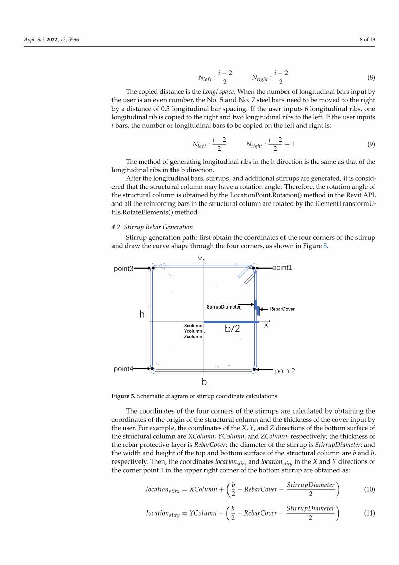
Stirrup generation path: first obtain the coordinates of the four corners of the stirrupand draw the curve shape through the four corners, as shown in Figure 5.
Appl. Sci. 2022, 12, x FOR PEER REVIEW 8 of 19
space, which can be calculated from information such as the number of longitudinal bars and the diameter of stirrups. Assuming that the number of longitudinal bars is Longi count, that is, the Longi space of longitudinal bars is:
2 2 1
b Protthickness Stirdia LongidiaLongi spacelongicount
− × − × −=−
(7)
When the number of longitudinal ribs is odd, for example, if the user inputs five lon-gitudinal ribs in the b direction, it is necessary to copy two longitudinal ribs from No. 5 and No. 7 longitudinal ribs, and to copy one longitudinal rib to the left and right sides, respectively. Then, if i bars are input, the number N of longitudinal bars that need to be copied on the left and right is:
2 2: :2 2left righti iN N− −
(8)
The copied distance is the Longi space. When the number of longitudinal bars input by the user is an even number, the No. 5 and No. 7 steel bars need to be moved to the right by a distance of 0.5 longitudinal bar spacing. If the user inputs 6 longitudinal ribs, one longitudinal rib is copied to the right and two longitudinal ribs to the left. If the user inputs i bars, the number of longitudinal bars to be copied on the left and right is:
2 2: : 12 2left righti iN N− − − (9)
The method of generating longitudinal ribs in the h direction is the same as that of the longitudinal ribs in the b direction.
After the longitudinal bars, stirrups, and additional stirrups are generated, it is con-sidered that the structural column may have a rotation angle. Therefore, the rotation angle of the structural column is obtained by the LocationPoint.Rotation() method in the Revit API, and all the reinforcing bars in the structural column are rotated by the ElementTrans-formUtils.RotateElements() method.
4.2. Stirrup Rebar Generation Stirrup generation path: first obtain the coordinates of the four corners of the stirrup
and draw the curve shape through the four corners, as shown in Figure 5.
Figure 5. Schematic diagram of stirrup coordinate calculations. Figure 5. Schematic diagram of stirrup coordinate calculations.
The coordinates of the four corners of the stirrups are calculated by obtaining thecoordinates of the origin of the structural column and the thickness of the cover input bythe user. For example, the coordinates of the X, Y, and Z directions of the bottom surface ofthe structural column are XColumn, YColumn, and ZColumn, respectively; the thickness ofthe rebar protective layer is RebarCover; the diameter of the stirrup is StirrupDiameter; andthe width and height of the top and bottom surface of the structural column are b and h,respectively. Then, the coordinates locationstirx and locationstiry in the X and Y directions ofthe corner point 1 in the upper right corner of the bottom stirrup are obtained as:
locationstirx = XColumn +
(b2− RebarCover − StirrupDiameter
2
)(10)
locationstiry = YColumn +
(h2− RebarCover − StirrupDiameter
2
)(11)

Appl. Sci. 2022, 12, 5596 9 of 19
Since the currently acquired origin coordinates are the coordinates of the bottomsurface of the structural column, the coordinates of the corner point 1 in the Z direction,that is, the coordinates in the height direction, are the Z coordinates of the bottom surfaceof the structural column plus the protective layer of the bottom surface of the rebar plushalf the diameter of the stirrup. The calculated coordinates locationstirz are:
locationstirz = ZColumn + BottomRebarCover +StirrupDiameter
2(12)
As shown in Figure 6, the coordinates of the four corners of the stirrups on the topsurface of the structural column and the coordinates of the four corners of the stirrups onthe bottom of the structural column are different only in the Z direction, that is, the heightdirection. The Z coordinate of the stirrups on the top surface of the structural column,Tlocationstirz, is:
Tlocationstirz = ZColumn + ColumnHight − TopRebarCover − StirrupDiameter2
(13)
Appl. Sci. 2022, 12, x FOR PEER REVIEW 9 of 19
The coordinates of the four corners of the stirrups are calculated by obtaining the coordinates of the origin of the structural column and the thickness of the cover input by the user. For example, the coordinates of the X, Y, and Z directions of the bottom surface of the structural column are XColumn, YColumn, and ZColumn, respectively; the thickness of the rebar protective layer is RebarCover; the diameter of the stirrup is StirrupDiameter; and the width and height of the top and bottom surface of the structural column are b and h, respectively. Then, the coordinates locationstirx and locationstiry in the X and Y directions of the corner point 1 in the upper right corner of the bottom stirrup are obtained as:
2 2stirxb StirrupDiameterlocation XColumn RebarCover = + − −
(10)
2 2stiryh StirrupDiameterlocation YColumn RebarCover = + − −
(11)
Since the currently acquired origin coordinates are the coordinates of the bottom sur-face of the structural column, the coordinates of the corner point 1 in the Z direction, that is, the coordinates in the height direction, are the Z coordinates of the bottom surface of the structural column plus the protective layer of the bottom surface of the rebar plus half the diameter of the stirrup. The calculated coordinates locationstirz are:
2stirzStirrupDiameterlocation ZColumn BottomRebarCover= + + (12)
As shown in Figure 6, the coordinates of the four corners of the stirrups on the top surface of the structural column and the coordinates of the four corners of the stirrups on the bottom of the structural column are different only in the Z direction, that is, the height direction. The Z coordinate of the stirrups on the top surface of the structural column, Tlocationstirz, is:
2stirzStirrupDiameterTlocation ZColumn ColumnHight TopRebarCover= + − −
(13)
Figure 6. Schematic diagram of the stirrup height coordinate calculations.
ColumnHight is the height of the current structural column. The method in the Revit API to get the height of a structural column is get_Parame-
ter(). In this way, the coordinates of the four corner points needed to generate the stirrups on the top surface of the structural column can be calculated.
When the coordinates of all corner points of the top and bottom stirrups of the struc-tural column are calculated, use the Line.CreateBound() method in the Revit API and pass the coordinates of two points in the parameters of the method to create a line. Pass through corner 1 and corner 2 to create the first line; pass through corner 2 and corner 3 to create the second line; pass through corner 3 and corner 4 to create the third line; pass through
Figure 6. Schematic diagram of the stirrup height coordinate calculations.
ColumnHight is the height of the current structural column.The method in the Revit API to get the height of a structural column is get_Parameter().
In this way, the coordinates of the four corner points needed to generate the stirrups on thetop surface of the structural column can be calculated.
When the coordinates of all corner points of the top and bottom stirrups of the struc-tural column are calculated, use the Line.CreateBound() method in the Revit API and passthe coordinates of two points in the parameters of the method to create a line. Pass throughcorner 1 and corner 2 to create the first line; pass through corner 2 and corner 3 to createthe second line; pass through corner 3 and corner 4 to create the third line; pass throughcorner 4 and corner 1 to create a fourth line. The final result is a closed quadrilateralwireframe. Add four lines to the List<Curve> collection.
Use the Rebar.CreateFromCurves() method for creating bars from curves in the RevitAPI. Enter the parameters, such as the diameter of the stirrup, the hook of the stirrup,and the direction of the bending structure entered by the user in the parentheses, andpass in the List<Curve> collection containing four lines, and then the stirrup is generatedaccording to the quadrilateral wire frame formed by the four lines. If the four incominglines are not connected end to end, the program will report an error and cannot generatestirrups normally.
4.3. Additional Stirrup Generation
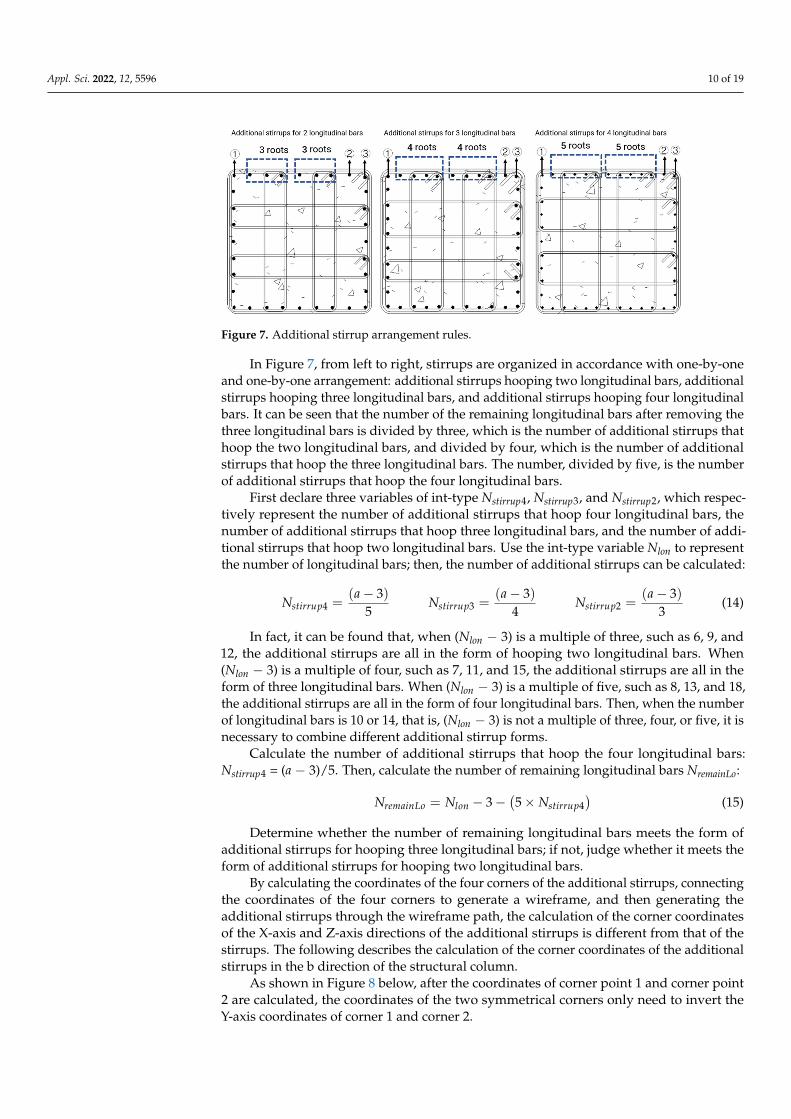
The number of additional stirrups is generated according to the number of longitudinalbars, as shown in Figure 7. By finding the relationship between the number of additionalstirrups and the number of longitudinal bars, and considering the least cost direction, thisprogram develops a calculation method, so that the program can automatically calculatethe form and size of the additional stirrups through the number of longitudinal bars inputby the user according to quantity and automatically arrange it in the structural column.
Appl. Sci. 2022, 12, 5596 10 of 19
Appl. Sci. 2022, 12, x FOR PEER REVIEW 10 of 19
corner 4 and corner 1 to create a fourth line. The final result is a closed quadrilateral wireframe. Add four lines to the List<Curve> collection.
Use the Rebar.CreateFromCurves() method for creating bars from curves in the Revit API. Enter the parameters, such as the diameter of the stirrup, the hook of the stirrup, and the direction of the bending structure entered by the user in the parentheses, and pass in the List<Curve> collection containing four lines, and then the stirrup is generated accord-ing to the quadrilateral wire frame formed by the four lines. If the four incoming lines are not connected end to end, the program will report an error and cannot generate stirrups normally.
4.3. Additional Stirrup Generation The number of additional stirrups is generated according to the number of longitu-
dinal bars, as shown in Figure 7. By finding the relationship between the number of addi-tional stirrups and the number of longitudinal bars, and considering the least cost direc-tion, this program develops a calculation method, so that the program can automatically calculate the form and size of the additional stirrups through the number of longitudinal bars input by the user according to quantity and automatically arrange it in the structural column.
Figure 7. Additional stirrup arrangement rules.
In Figure 7, from left to right, stirrups are organized in accordance with one-by-one and one-by-one arrangement: additional stirrups hooping two longitudinal bars, addi-tional stirrups hooping three longitudinal bars, and additional stirrups hooping four lon-gitudinal bars. It can be seen that the number of the remaining longitudinal bars after removing the three longitudinal bars is divided by three, which is the number of addi-tional stirrups that hoop the two longitudinal bars, and divided by four, which is the num-ber of additional stirrups that hoop the three longitudinal bars. The number, divided by five, is the number of additional stirrups that hoop the four longitudinal bars.
First declare three variables of int-type Nstirrup4, Nstirrup3, and Nstirrup2, which respectively represent the number of additional stirrups that hoop four longitudinal bars, the number of additional stirrups that hoop three longitudinal bars, and the number of additional stir-rups that hoop two longitudinal bars. Use the int-type variable Nlon to represent the num-ber of longitudinal bars; then, the number of additional stirrups can be calculated:
( ) ( ) ( )4 3 2
3 3 3
5 4 3stirrup stirrup stirrupa a a
N N N− − −
= = = (14)
In fact, it can be found that, when (Nlon − 3) is a multiple of three, such as 6, 9, and 12, the additional stirrups are all in the form of hooping two longitudinal bars. When (Nlon − 3) is a multiple of four, such as 7, 11, and 15, the additional stirrups are all in the form of three longitudinal bars. When (Nlon − 3) is a multiple of five, such as 8, 13, and 18, the
Figure 7. Additional stirrup arrangement rules.
In Figure 7, from left to right, stirrups are organized in accordance with one-by-oneand one-by-one arrangement: additional stirrups hooping two longitudinal bars, additionalstirrups hooping three longitudinal bars, and additional stirrups hooping four longitudinalbars. It can be seen that the number of the remaining longitudinal bars after removing thethree longitudinal bars is divided by three, which is the number of additional stirrups thathoop the two longitudinal bars, and divided by four, which is the number of additionalstirrups that hoop the three longitudinal bars. The number, divided by five, is the numberof additional stirrups that hoop the four longitudinal bars.
First declare three variables of int-type Nstirrup4, Nstirrup3, and Nstirrup2, which respec-tively represent the number of additional stirrups that hoop four longitudinal bars, thenumber of additional stirrups that hoop three longitudinal bars, and the number of addi-tional stirrups that hoop two longitudinal bars. Use the int-type variable Nlon to representthe number of longitudinal bars; then, the number of additional stirrups can be calculated:
Nstirrup4 =(a − 3)
5Nstirrup3 =
(a − 3)4
Nstirrup2 =(a − 3)
3(14)
In fact, it can be found that, when (Nlon − 3) is a multiple of three, such as 6, 9, and12, the additional stirrups are all in the form of hooping two longitudinal bars. When(Nlon − 3) is a multiple of four, such as 7, 11, and 15, the additional stirrups are all in theform of three longitudinal bars. When (Nlon − 3) is a multiple of five, such as 8, 13, and 18,the additional stirrups are all in the form of four longitudinal bars. Then, when the numberof longitudinal bars is 10 or 14, that is, (Nlon − 3) is not a multiple of three, four, or five, it isnecessary to combine different additional stirrup forms.
Calculate the number of additional stirrups that hoop the four longitudinal bars:Nstirrup4 = (a − 3)/5. Then, calculate the number of remaining longitudinal bars NremainLo:
NremainLo = Nlon − 3 −(5 × Nstirrup4
)(15)
Determine whether the number of remaining longitudinal bars meets the form ofadditional stirrups for hooping three longitudinal bars; if not, judge whether it meets theform of additional stirrups for hooping two longitudinal bars.
By calculating the coordinates of the four corners of the additional stirrups, connectingthe coordinates of the four corners to generate a wireframe, and then generating theadditional stirrups through the wireframe path, the calculation of the corner coordinatesof the X-axis and Z-axis directions of the additional stirrups is different from that of thestirrups. The following describes the calculation of the corner coordinates of the additionalstirrups in the b direction of the structural column.
As shown in Figure 8 below, after the coordinates of corner point 1 and corner point2 are calculated, the coordinates of the two symmetrical corners only need to invert theY-axis coordinates of corner 1 and corner 2.

Appl. Sci. 2022, 12, 5596 11 of 19
Appl. Sci. 2022, 12, x FOR PEER REVIEW 11 of 19
additional stirrups are all in the form of four longitudinal bars. Then, when the number of longitudinal bars is 10 or 14, that is, (Nlon − 3) is not a multiple of three, four, or five, it is necessary to combine different additional stirrup forms.
Calculate the number of additional stirrups that hoop the four longitudinal bars: Nstir-
rup4 = (a − 3)/5. Then, calculate the number of remaining longitudinal bars NremainLo:
( )43 5remainLo lon stirrupN N N= − − × (15)
Determine whether the number of remaining longitudinal bars meets the form of ad-ditional stirrups for hooping three longitudinal bars; if not, judge whether it meets the form of additional stirrups for hooping two longitudinal bars.
By calculating the coordinates of the four corners of the additional stirrups, connect-ing the coordinates of the four corners to generate a wireframe, and then generating the additional stirrups through the wireframe path, the calculation of the corner coordinates of the X-axis and Z-axis directions of the additional stirrups is different from that of the stirrups. The following describes the calculation of the corner coordinates of the additional stirrups in the b direction of the structural column.
As shown in Figure 8 below, after the coordinates of corner point 1 and corner point 2 are calculated, the coordinates of the two symmetrical corners only need to invert the Y-axis coordinates of corner 1 and corner 2.
Figure 8. T schematic diagram of the coordinates of the corner points of the additional stirrups.
In a manner that is the same as above, the distance between longitudinal bars is Longi space; the thickness of the protective layer is Prot thickness; the diameter of stirrups is Stir dia; the diameter of longitudinal bars is Longi dia; and the diameter of additional stirrups is Add dia. The coordinate locationaddx1 in the X direction of point 1 is:
1 2
2 2addxb Add dialocation Prot thickness Stir dia Longispace= − − − × + (16)
The additional stirrup form in the current figure is an additional stirrup that hoops two longitudinal bars. It can be seen that the X-direction coordinate locationaddx1 of the cor-ner point 1 of the i-th additional stirrup is:
( )1 2 3
2 2addxb Add dialocation Prot thickness Stir dia i Longispace= − − − + × × + (17)
If the current additional stirrups are in the form of three bars or four bars, the X-direction coordinate locationaddx1 of the corner point 1 of the i-th additional stirrup is:
( )1 2 4
2 2addxb Add dialocation Prot thickness Stir dia i Longispace= − − − + × × + (18)
Figure 8. T schematic diagram of the coordinates of the corner points of the additional stirrups.
In a manner that is the same as above, the distance between longitudinal bars is Longispace; the thickness of the protective layer is Prot thickness; the diameter of stirrups is Stirdia; the diameter of longitudinal bars is Longi dia; and the diameter of additional stirrups isAdd dia. The coordinate locationaddx1 in the X direction of point 1 is:
locationaddx1 =b2− Prot thickness − Stir dia − 2 × Longi space +
Add dia2
(16)
The additional stirrup form in the current figure is an additional stirrup that hoopstwo longitudinal bars. It can be seen that the X-direction coordinate locationaddx1 of thecorner point 1 of the i-th additional stirrup is:
locationaddx1 =b2− Prot thickness − Stir dia − (2 + 3 × i)× Longi space +
Add dia2
(17)
If the current additional stirrups are in the form of three bars or four bars, theX-direction coordinate locationaddx1 of the corner point 1 of the i-th additional stirrup is:
locationaddx1 =b2− Prot thickness − Stir dia − (2 + 4 × i)× Longi space +
Add dia2
(18)
Compared with the corner point 1, the X coordinate of the corner point 2 has an extradistance of the longitudinal rib spacing longi space and the longitudinal rib diameter longidia; then, the X direction coordinate locationaddx2 of the corner point 2 is:
locationaddx2 =b2− Prot thickness − Stir dia − (2 + 1)× Longi space − longi dia − Add dia
2(19)
Compared with the corner point 2, the corner point 2-1 of the second additional stirrupin the above figure has three more longitudinal rebar distances longi space. For the samereason, the X-direction coordinate locationaddx2 at the corner point 2 of the i-th additionalstirrup can be obtained as:
locationaddx2 =b2− Prot thickness − Stir dia − (2 + 3 × i + 1)× Longi space − longi dia − Add dia
2(20)
When the additional stirrup type is the additional stirrup form that hoops three orfour longitudinal bars, the X-direction coordinate locationaddx2 of the corner point 2 of thei-th additional stirrup is:
locationaddx2 =b2− Prot thickness − Stir dia − (2 + 4 × i + 2)× Longi space − longi dia − Add dia
2(21)
locationaddx2 =b2− Prot thickness − Stir dia − (2 + 5 × i + 3)× Longi space − longi dia − Add dia
2(22)

Appl. Sci. 2022, 12, 5596 12 of 19
There are seven cases in the form of additional stirrups proposed above, and onlythree cases are currently discussed. That is, there are only additional stirrups that hooptwo longitudinal bars, only additional stirrups that hoop three longitudinal bars, and onlyadditional stirrups that hoop four longitudinal bars. In the above three cases, the additionalstirrups are generated in sequence from right to left.
When the additional stirrup form for hooping two longitudinal bars and the additionalstirrup form for hooping three longitudinal bars exist at the same time, first, the additionalstirrup forms that hoop three longitudinal bars are generated from left to right, and then theadditional stirrup forms that hoop two longitudinal bars are generated sequentially fromright to left. Declare three int-type variables Nstirrup4, Nstirrup3, Nstirrup2, which representthe number of generated three additional stirrup forms. From right to left, first generateadditional stirrups that hoops three longitudinal bars, and generate Nstirrup3 times in a loop.Then, from left to right, additional stirrups are generated to hoop the two longitudinal bars,and the loop is generated Nstirrup4 times.
The last case is that there is an additional stirrup form that hoops two longitudinal bars,an additional stirrup form that hoops three longitudinal bars, and an additional stirrupform that hoops four longitudinal bars. In this case, the additional stirrups that hoop thefour longitudinal bars are first generated from right to left, and the loops are generatedNstirrup4 times. Then, generate additional stirrups that hoop the three longitudinal bars inthe opposite direction, and cycle to generate Nstirrup3 times. Then, calculate the X-directioncoordinate locationaddx1 of the corner point 1 of the additional stirrups that hoop the twolongitudinal bars:
locationaddx1 =b2− Prot thickness − Stir dia −
(2 + 3 × i + Nstirrup4 × 5
)× Longi space +
Add dia2
(23)
5. Rebar Annotation Generation and Drawing Export
Use the GetShapeDrivenAccessor(). ComputeDrivingCurves() method to obtain thefour edge sets of stirrups. Iterate over the lines in the collection. Use the properties ofLine.Origin to obtain the coordinates of the four corners of the stirrup. The acquisitionsequence is to start from the upper right corner of the stirrup and acquire counterclockwise.Obtain the coordinates of the midpoints of the two edges of the stirrup and deduce thecoordinates of the two ends of the line segment to be drawn. Use the Line.CreatBound()method to draw line segments and use the Creat.NewDetailCurve() method to generatedetail lines. Draw an oblique line segment at the intersection of the detail line and thestirrup, and highlight it, as shown in Figure 9.
Appl. Sci. 2022, 12, x FOR PEER REVIEW 13 of 19
the coordinates of the two ends of the line segment to be drawn. Use the Line.Creat-Bound() method to draw line segments and use the Creat.NewDetailCurve() method to generate detail lines. Draw an oblique line segment at the intersection of the detail line and the stirrup, and highlight it, as shown in Figure 9.
Figure 9. Schematic diagram of the rebar dimension line.
After the structural column rebar information annotation is generated, use the Doc-ument.Export() method to export the current view to the CAD format. Use the DetailLevel property to set the current view to fine mode and use the DisplayStyle property to set the current view to wireframe mode. The exported CAD drawings are exported in the wireframe mode, which can clearly express information such as the number of longitudi-nal bars and the location of stirrups. Name the currently exported CAD drawing as the name of the current Revit view plus “rebar structure drawing”. If the current view name is level 2, the name of the exported CAD drawing is “level 2 rebar structure drawing”.
6. Rebar Information Export and Rebar Cutting Analysis 6.1. Information Export
Use Revit secondary development technology to export rebar information to Excel. It is convenient for the rebar assembly robot and the rebar automatic processing machine to read, which avoids the tedious work of manual input of information and the problem of easy errors. Using the NPOI toolkit, which is an open source development tool down-loaded from the NuGet package manager of visual studio, Excel versions 97–2003 and Excel and Word from versions 2007 and above can be read and written. Additionally, NPOI can read and write to Word or Excel when the user does not have Office installed.
In the Revit API, the rebar only has location information, that is, the Location point. It cannot be used for rebar installation, so this article uses the method of obtaining the centerline of the rebar. That is, the center line of the longitudinal bar is obtained, and then the coordinates of the two ends of the line are obtained. For stirrups, the center line of the stirrups is obtained, and the three-dimensional coordinates of the midpoints of the four sides of the stirrups are calculated. So, the longitudinal bar needs to obtain two points, and the stirrup needs four points.
The steel bar cutting length in Revit was included in the steel bar model information, and the steel bar cutting length can be exported by exporting the schedule. Schedules dis-play information extracted from element properties in a project in tabular form. The user can select the attributes of the element to export to the schedule, such as rebar length and volume.
Figure 9. Schematic diagram of the rebar dimension line.

Appl. Sci. 2022, 12, 5596 13 of 19
After the structural column rebar information annotation is generated, use the Docu-ment.Export() method to export the current view to the CAD format. Use the DetailLevelproperty to set the current view to fine mode and use the DisplayStyle property to setthe current view to wireframe mode. The exported CAD drawings are exported in thewireframe mode, which can clearly express information such as the number of longitudinalbars and the location of stirrups. Name the currently exported CAD drawing as the nameof the current Revit view plus “rebar structure drawing”. If the current view name is level2, the name of the exported CAD drawing is “level 2 rebar structure drawing”.
6. Rebar Information Export and Rebar Cutting Analysis6.1. Information Export
Use Revit secondary development technology to export rebar information to Excel. Itis convenient for the rebar assembly robot and the rebar automatic processing machine toread, which avoids the tedious work of manual input of information and the problem ofeasy errors. Using the NPOI toolkit, which is an open source development tool downloadedfrom the NuGet package manager of visual studio, Excel versions 97–2003 and Excel andWord from versions 2007 and above can be read and written. Additionally, NPOI can readand write to Word or Excel when the user does not have Office installed.
In the Revit API, the rebar only has location information, that is, the Location point.It cannot be used for rebar installation, so this article uses the method of obtaining thecenterline of the rebar. That is, the center line of the longitudinal bar is obtained, and thenthe coordinates of the two ends of the line are obtained. For stirrups, the center line of thestirrups is obtained, and the three-dimensional coordinates of the midpoints of the foursides of the stirrups are calculated. So, the longitudinal bar needs to obtain two points, andthe stirrup needs four points.
The steel bar cutting length in Revit was included in the steel bar model information,and the steel bar cutting length can be exported by exporting the schedule. Schedulesdisplay information extracted from element properties in a project in tabular form. Theuser can select the attributes of the element to export to the schedule, such as rebar lengthand volume.
Before exporting the rebar list, more options need to be selected, and due to thelarge number of rebars, the rebar information in the list is not very clear, and there isa considerable amount of repeated information. The Revit schedule cannot be directlyexported into Excel. It needs to be exported as a TXT text first, and then read using Excel.
The export steps are cumbersome. This section introduces the use of Revit secondarydevelopment technology to directly export the rebar model information in Revit into anExcel table, which improves the information export efficiency and helps the staff to operatethe data later. The export method is the same as the export coordinate method.
6.2. Rebar Cutting Length Calculation
To calculate the cutting length of the steel bar, the difference in the size of the steel barskin under different bending angles of the steel bar should be calculated first. When thebending angle of the steel bar is less than or equal to 90 degrees, as shown in Figure 10, thedifference between JK+KL and arc ab is calculated. The calculation steps are as follows.
JK = KL = R + d × tanα
2(24)
ab =
(R +
d2
)× π × α
180(25)
JK + KL − ab = 2 × R + d × tanα
2−
(R +
d2
)× π × α
180(26)

Appl. Sci. 2022, 12, 5596 14 of 19
Appl. Sci. 2022, 12, x FOR PEER REVIEW 14 of 19
Before exporting the rebar list, more options need to be selected, and due to the large number of rebars, the rebar information in the list is not very clear, and there is a consid-erable amount of repeated information. The Revit schedule cannot be directly exported into Excel. It needs to be exported as a TXT text first, and then read using Excel.
The export steps are cumbersome. This section introduces the use of Revit secondary development technology to directly export the rebar model information in Revit into an Excel table, which improves the information export efficiency and helps the staff to oper-ate the data later. The export method is the same as the export coordinate method.
6.2. Rebar Cutting Length Calculation To calculate the cutting length of the steel bar, the difference in the size of the steel
bar skin under different bending angles of the steel bar should be calculated first. When the bending angle of the steel bar is less than or equal to 90 degrees, as shown in Figure 10, the difference between JK+KL and arc ab is calculated. The calculation steps are as fol-lows.
Figure 10. Schematic diagram of the calculation of the steel bar cutting length.
2JK KL R d tanα= = + × (24)
2 180dab R απ = + × ×
(25)
22 2 180
dJK KL ab R d tan Rα απ + − = × + × − + × ×
(26)
The steel bar skin difference with a bending angle of less than or equal to 90 degrees can be calculated by applying the above formula. Only the bending angle α of the steel bar, the bending radius R of the steel bar, and the diameter d of the steel bar are needed to calculate the difference of the steel bar skin. Combined with the steel bar skin size in the construction drawing, the steel bar cutting length can be obtained by using the differ-ence between the steel bar skin size and the calculated difference value of the steel bar skin.
A variety of optimization algorithms can be used to optimize the steel bar cutting method, such as linear programming methods and genetic algorithms.
Figure 10. Schematic diagram of the calculation of the steel bar cutting length.
The steel bar skin difference with a bending angle of less than or equal to 90 degreescan be calculated by applying the above formula. Only the bending angle α of the steelbar, the bending radius R of the steel bar, and the diameter d of the steel bar are needed tocalculate the difference of the steel bar skin. Combined with the steel bar skin size in theconstruction drawing, the steel bar cutting length can be obtained by using the differencebetween the steel bar skin size and the calculated difference value of the steel bar skin.
A variety of optimization algorithms can be used to optimize the steel bar cuttingmethod, such as linear programming methods and genetic algorithms.
7. Research and Application of BIM Technology in MR
Mixed reality technology is now used in the medical, manufacturing, and retail indus-tries. Microsoft has cooperated with companies in various industries, such as ANSYS, Hon-eywell, and ABB, in mixed reality technology to help them to build their own ecosystems.
At present, mixed reality technology still has a large space for development in the fieldof construction engineering, improve project efficiency and reduce rework, improve thecoordination between various disciplines, realize digital construction, and visualize con-struction data, and promote the transformation of the construction industry to intelligenceand data. In this section, the structural rebar model in Revit is imported into Unity3D formixed reality development and interaction with the model in HoloLens2. This enablesbetter communication to facilitate faster and more effective decision making to win bids,detect errors earlier, avoid harm, among others. It also facilitates interactive design reviewsamong all project stakeholders.
Create a new 3D project, enter the project name, and select the project save locationto create a new Unity3D file. Unity3D has high requirements on computer configuration.If the computer configuration is general, such as a computer without a discrete graphicscard, it may take a long time to load as computers for 3D modeling and scene renderinguse discrete graphics cards whenever possible. The interface for creating a new Unity3Dfile is shown in Figure 11.
The Unity3D interface can be adjusted according to personal habits. The followingfigure is the interface that was adjusted. Frequently used function panels include Hierarchyview, Project view, Scene view, Game view, and Inspector view. The Hierarchy view showsthe names of all objects in the current scene. Select the name to highlight the current objectin the scene view. The project view stores all the resources in the entire project, including3D model files, pictures, music, scripts, and text. You can directly drag and drop the filesrequired by the project to the Project list by dragging and dropping. The list has a separatefolder at the root of the file. The Scene view is used to display objects that the current user

Appl. Sci. 2022, 12, 5596 15 of 19
created. The user can choose to create a new 3D or 2D object in the GameObject option ofthe menu bar, and the new object will appear in the scene view.
Appl. Sci. 2022, 12, x FOR PEER REVIEW 15 of 19
7. Research and Application of BIM Technology in MR Mixed reality technology is now used in the medical, manufacturing, and retail in-
dustries. Microsoft has cooperated with companies in various industries, such as ANSYS, Honeywell, and ABB, in mixed reality technology to help them to build their own ecosys-tems.
At present, mixed reality technology still has a large space for development in the field of construction engineering, improve project efficiency and reduce rework, improve the coordination between various disciplines, realize digital construction, and visualize construction data, and promote the transformation of the construction industry to intelli-gence and data. In this section, the structural rebar model in Revit is imported into Unity3D for mixed reality development and interaction with the model in HoloLens2. This enables better communication to facilitate faster and more effective decision making to win bids, detect errors earlier, avoid harm, among others. It also facilitates interactive design reviews among all project stakeholders.
Create a new 3D project, enter the project name, and select the project save location to create a new Unity3D file. Unity3D has high requirements on computer configuration. If the computer configuration is general, such as a computer without a discrete graphics card, it may take a long time to load as computers for 3D modeling and scene rendering use discrete graphics cards whenever possible. The interface for creating a new Unity3D file is shown in Figure 11.
Figure 11. Create a new unity project.
The Unity3D interface can be adjusted according to personal habits. The following figure is the interface that was adjusted. Frequently used function panels include Hierar-chy view, Project view, Scene view, Game view, and Inspector view. The Hierarchy view shows the names of all objects in the current scene. Select the name to highlight the current object in the scene view. The project view stores all the resources in the entire project, including 3D model files, pictures, music, scripts, and text. You can directly drag and drop the files required by the project to the Project list by dragging and dropping. The list has a separate folder at the root of the file. The Scene view is used to display objects that the current user created. The user can choose to create a new 3D or 2D object in the GameOb-ject option of the menu bar, and the new object will appear in the scene view.
Microsoft provides the Mixed Reality Toolkit (MRTK) for users who use Unity3D for mixed reality development. Click the Start button to start setting up the toolkit to import the project. Select the project path; the project must contain the Asset folder or, otherwise, the export will be unsuccessful.
Figure 11. Create a new unity project.
Microsoft provides the Mixed Reality Toolkit (MRTK) for users who use Unity3D formixed reality development. Click the Start button to start setting up the toolkit to importthe project. Select the project path; the project must contain the Asset folder or, otherwise,the export will be unsuccessful.
After selecting the project path, several extension package options will appear on theinterface, allowing users to choose the toolkit to be imported. There are mixed reality casetoolkits, extension packages, among others. Generally, there are three kinds of packagesthat need to be imported, namely, the mixed reality basic toolkit, Mixed Reality ToolkitFoundation; the mixed reality extension package, Mixed Reality Toolkit Extensions; andthe mixed reality case package, Mixed Reality Toolkit Examples. The basic toolkit is arequirement, as it contains the basic files needed for mixed reality development. Thedevelopment kit interface is shown in Figure 12.
Set OpenXR options. Under the Edit option in the menu bar, find Project Settings toopen the project settings interface. Select the Player option and enter the package name.Select the Open XR option, check the Microsoft HoloLens option, and select features, suchas hand tracking. After setting, click Apply. Select Mixed Reality Toolkit in the Hierarchypanel, check whether the mounted script is DefaultMixedRealityToolkitConfigurationPro-file in the Inspector, and save the current scene after checking.
After the scene is saved, the user needs to compile the current project with VisualStudio. Click Build Settings under the File option in the menu bar; the Build Settingswindow pops up and check whether the Platform is Windows Platform. Set the targetdevice to HoloLens, click the Build button, and select a folder to build the scene. After thebuild is complete, a solution of type sln file is generated in the folder. Use Visual Studio toopen this file, select the Release architecture as ARM64 to be compatible with HoloLens2,and use ×86 for HoloLens1. Connect the HoloLens2 device to the computer and select StartWithout Debugging under the Debug option in the Visual Studio menu bar to completethe compilation.

Appl. Sci. 2022, 12, 5596 16 of 19
Appl. Sci. 2022, 12, x FOR PEER REVIEW 16 of 19
After selecting the project path, several extension package options will appear on the interface, allowing users to choose the toolkit to be imported. There are mixed reality case toolkits, extension packages, among others. Generally, there are three kinds of packages that need to be imported, namely, the mixed reality basic toolkit, Mixed Reality Toolkit Foundation; the mixed reality extension package, Mixed Reality Toolkit Extensions; and the mixed reality case package, Mixed Reality Toolkit Examples. The basic toolkit is a re-quirement, as it contains the basic files needed for mixed reality development. The devel-opment kit interface is shown in Figure 12.
Figure 12. Mixed Reality Toolkit.
Set OpenXR options. Under the Edit option in the menu bar, find Project Settings to open the project settings interface. Select the Player option and enter the package name. Select the Open XR option, check the Microsoft HoloLens option, and select features, such as hand tracking. After setting, click Apply. Select Mixed Reality Toolkit in the Hierarchy panel, check whether the mounted script is DefaultMixedRealityToolkitConfiguration-Profile in the Inspector, and save the current scene after checking.
After the scene is saved, the user needs to compile the current project with Visual Studio. Click Build Settings under the File option in the menu bar; the Build Settings win-dow pops up and check whether the Platform is Windows Platform. Set the target device to HoloLens, click the Build button, and select a folder to build the scene. After the build is complete, a solution of type sln file is generated in the folder. Use Visual Studio to open this file, select the Release architecture as ARM64 to be compatible with HoloLens2, and use ×86 for HoloLens1. Connect the HoloLens2 device to the computer and select Start Without Debugging under the Debug option in the Visual Studio menu bar to complete the compilation.
In order to more accurately view and manipulate the model in HoloLens2, the user needs to mount the Object Manipulator script and the NearInteractionGrabbable script to the model in Unity. The Object Manipulator script enables users to rotate and move ob-jects and is suitable for joint hand and hand ray operations in HoloLens2. The NearInter-actionGrabbable script can make the object’s gesture input response more accurate. The result is shown in Figure 13.
Figure 12. Mixed Reality Toolkit.
In order to more accurately view and manipulate the model in HoloLens2, the userneeds to mount the Object Manipulator script and the NearInteractionGrabbable script tothe model in Unity. The Object Manipulator script enables users to rotate and move objectsand is suitable for joint hand and hand ray operations in HoloLens2. The NearInteraction-Grabbable script can make the object’s gesture input response more accurate. The result isshown in Figure 13.
Appl. Sci. 2022, 12, x FOR PEER REVIEW 17 of 19
Figure 13. Interaction with the Revit model in mixed reality.
The model provides a new way of project presentation for designers in the field of construction engineering. In the process of construction management, the project is dis-played in real time based on the BIM model information of the column steel bar, so that the relevant personnel of the project can better deal with the quality problems that may occur during the construction process for possible design changes and timely technical communication. Moreover, because the steel bar is a hidden project, it cannot be reworked and viewed after the concrete is poured, which increases the burden on the entity under-standing of the hidden project. Through the Revit model combined with the mixed reality technology, the relevant personnel of the project can view the steel bar information at any time.
In this section, the rebar cage model in Revit was imported into Unity3D, and MRTK was configured through the above method. Mount the corresponding components to the rebar cage model, write corresponding scripts, and realize the interaction with the Revit model in mixed reality.
8. Conclusions In this work, a program for automatic generation of rebar parametric model in Revit
was developed, which improves the modeling efficiency and modeling accuracy of rebar engineering. Combined with WPF technology, the program operation interface was de-veloped to increase the operability of the program, realize the automatic export of 2D re-bar CAD drawings from the 3D model of rebar, complete the forward design process from 3D model to 2D drawings, and provide a reference for the subsequent research on the forward design of rebar engineering automation. Reinforcing bar information was ex-ported, and the bar cutting method was analyzed. Through the development of the mixed reality device HoloLens2, the interaction between the rebar model and the human hand was realized, which improves the visualization of the rebar engineering, and provides a reference for the follow-up construction operation and maintenance research. Based on the above steps, the process of intelligent construction of steel bars was realized, and we conclude the following: 1. Use the C# programming language for secondary development based on Revit and
use the rebar generation method in the Revit API. Realize the automatic generation of longitudinal rebar model, stirrup model and additional stirrup model in Revit. The user can customize the diameter of the rebar to be generated, the thickness of the protective layer, and the number of longitudinal rebar. According to the height of the rebar area entered by the user, the program can automatically generate stirrups in
Figure 13. Interaction with the Revit model in mixed reality.
The model provides a new way of project presentation for designers in the field of con-struction engineering. In the process of construction management, the project is displayedin real time based on the BIM model information of the column steel bar, so that the relevantpersonnel of the project can better deal with the quality problems that may occur duringthe construction process for possible design changes and timely technical communication.Moreover, because the steel bar is a hidden project, it cannot be reworked and viewed

Appl. Sci. 2022, 12, 5596 17 of 19
after the concrete is poured, which increases the burden on the entity understanding of thehidden project. Through the Revit model combined with the mixed reality technology, therelevant personnel of the project can view the steel bar information at any time.
In this section, the rebar cage model in Revit was imported into Unity3D, and MRTKwas configured through the above method. Mount the corresponding components to therebar cage model, write corresponding scripts, and realize the interaction with the Revitmodel in mixed reality.
8. Conclusions
In this work, a program for automatic generation of rebar parametric model in Revitwas developed, which improves the modeling efficiency and modeling accuracy of rebarengineering. Combined with WPF technology, the program operation interface was devel-oped to increase the operability of the program, realize the automatic export of 2D rebarCAD drawings from the 3D model of rebar, complete the forward design process from 3Dmodel to 2D drawings, and provide a reference for the subsequent research on the forwarddesign of rebar engineering automation. Reinforcing bar information was exported, and thebar cutting method was analyzed. Through the development of the mixed reality deviceHoloLens2, the interaction between the rebar model and the human hand was realized,which improves the visualization of the rebar engineering, and provides a reference for thefollow-up construction operation and maintenance research. Based on the above steps, theprocess of intelligent construction of steel bars was realized, and we conclude the following:
1. Use the C# programming language for secondary development based on Revit anduse the rebar generation method in the Revit API. Realize the automatic generation oflongitudinal rebar model, stirrup model and additional stirrup model in Revit. Theuser can customize the diameter of the rebar to be generated, the thickness of theprotective layer, and the number of longitudinal rebar. According to the height of therebar area entered by the user, the program can automatically generate stirrups in theencryption area and stirrups in the non-encryption area. At the same time, variousannotation information of the steel bar BIM model can be automatically generated,and CAD drawings can be automatically exported. To a large extent, the repetitivework is reduced, the modeling efficiency is improved, and the inaccurate and non-standard models caused by human errors are avoided. The forward drawing of therebar project is realized, which can better improve the work efficiency of the designer.
2. In order to realize the fully automatic processing of steel bars, using Revit secondarydevelopment technology combined with Visual Studio NuGet toolkit, the functionof exporting the location information and cutting information of the steel bar BIMmodel was realized. The steel bar information can be directly exported to an Exceltable, which can be used to read the information of the steel bar automatic processingequipment. The whole process of automatic processing of steel bars was realized,avoiding the mistakes that may be caused by manual operation. It can improve therebar processing rate and save labor costs. At the same time, it also avoids the safetyproblem of workers directly operating the machine to a certain extent.
3. A study on the application of BIM+MR technology in steel bar engineering. Unity3Ddevelops the HoloLens2, a mixed reality device. The Revit structural rebar modelwas imported into Unity3D to realize the interaction of the Revit model with thehuman hand in mixed reality. It enables owners, design, engineering, constructionand other parties in the engineering construction industry to experience and interactwith realistic 3D models in a virtual environment, accelerate design iteration, andhelp to realize digital construction guidance.
Accordingly, it makes the intelligent construction of steel bars possible and provides areference for subsequent steel bar construction research.

Appl. Sci. 2022, 12, 5596 18 of 19
Author Contributions: Conceptualization, D.W. Writing—original draft preparation, Y.H. All authorshave read and agreed to the published version of the manuscript.
Funding: This research was funded by [Natural Science Foundation of Shanghai] grant number[18ZR1414500].
Institutional Review Board Statement: Not applicable.
Informed Consent Statement: Not applicable.
Data Availability Statement: Not applicable.
Conflicts of Interest: The authors declare no conflict of interest.
References1. Zheng, C.; Yi, C.; Lu, M. Integrated optimization of rebar detailing design and installation planning for waste reduction and
productivity improvement. Autom. Constr. 2019, 101, 32–47. [CrossRef]2. Chan, A.P.; Yi, W.; Wong, D.P.; Yam, M.C.; Chan, D.W. Determining an optimal recovery time for construction rebar workers after
working to exhaustion in a hot and humid environment. Build. Environ. 2012, 58, 163–171. [CrossRef]3. Dong, S.; Wang, L.; Huang, W. Research on Intelligent Construction Intensive Management Based on Building Information
Modeling Technology. IOP Conf. Ser. Earth Environ. Sci. 2021, 783, 012106. [CrossRef]4. Zhang, Y.; Yuen, K.V. Applications of Deep Learning in Intelligent Construction. In Structural Health Monitoring Based on Data
Science Techniques; Springer: Cham, Switzerland, 2022; pp. 227–245.5. Wu, Z.; Zhou, C. Intelligent construction of smart stadiums and strategies for promoting the development of national fitness. J.
Intell. Fuzzy Syst. 2021, 1–7. [CrossRef]6. Wen, Y.; Albert, C. Effects of Heat Stress on Construction Labor Productivity in Hong Kong: A Case Study of Rebar Workers. Int.
J. Environ. Res. Public Health 2017, 14, 1055.7. Li, X.; Chow, K.H.; Zhu, Y.; Lin, Y. Evaluating the impacts of high-temperature outdoor working environments on construction
labor productivity in China: A case study of rebar workers. Build. Environ. 2016, 95, 42–52. [CrossRef]8. Wen, Y.; Chan, A. Optimizing work–rest schedule for construction rebar workers in hot and humid environment. Build. Environ.
2013, 61, 104–113.9. Matviyishyn, Y.; Janiak, T. Minimization of steel waste during manufacture of reinforced concrete structures. In AIP Conference
Proceedings; AIP Publishing LLC: Melville, NY, USA, 2019.10. Wang, J.; Seo, J.; Siu, M.F.F.; Hwang, S.; Yu, K. Workload Analysis of Rebar Worker Using Wearable Wristband in Hong Kong
6-Day Cycle Building Construction. In Proceedings of the CIB World Building Congress 2019, Hong Kong, 17–21 June 2019.11. Abbas, A.; Seo, J.; Kim, M.K. Exploring the Construction Task Performance and Cognitive Workload of Augmented Reality-
Assisted Rebar Inspection Tasks. In Proceedings of the Construction Research Congress 2020, Tempe, AZ, USA, 8–10 March 2020.12. Troncoso-Pastoriza, F.; Eguia-Oller, P.; Diaz-Redondo, R.P.; Granada-Alvarez, E. Use of BIM data as input and output for improved
detection of lighting elements in buildings. Autom. Constr. 2019, 106, 102852. [CrossRef]13. Bortolini, R.; Formoso, C.T.; Viana, D.D. Site logistics planning and control for engineer-to-order prefabricated building systems
using BIM 4D modeling. Autom. Constr. 2019, 98, 248–264. [CrossRef]14. Kamel, E.; Memari, A.M. Review of BIM’s application in energy simulation: Tools, issues, and solutions. Autom. Constr. 2019, 97,
164–180. [CrossRef]15. Yilmaz, G.; Akcamete, A.; Demirors, O. A reference model for BIM capability assessments. Autom. Constr. 2019, 101, 245–263.
[CrossRef]16. Basta, A.; Serror, M.H.; Marzouk, M. A BIM-based framework for quantitative assessment of steel structure deconstructability.
Autom. Constr. 2020, 111, 103064.1–103064.12. [CrossRef]17. Wang, C.; Li, H.; Kho, S.Y. VR-embedded BIM immersive system for QS engineering education. Comput. Appl. Eng. Educ. 2018,
26, 626–641. [CrossRef]18. Weng, Y.; Mohamed, N.A.N.; Lee, B.J.S.; Gan, N.J.H.; Li, M.; Jen Tan, M.; Li, H.; Qian, S. Extracting BIM Information for Lattice
Toolpath Planning in Digital Concrete Printing with Developed Dynamo Script: A Case Study. J. Comput. Civ. Eng. 2021, 35,05021001. [CrossRef]
19. Carvalho, J.P.; Bragana, L.; Mateus, R. Sustainable building design: Analysing the feasibility of BIM platforms to support practicalbuilding sustainability assessment. Comput. Ind. 2021, 127, 103400. [CrossRef]
20. Abdulaziz Almarzooq, S.; Al-Shaalan, A.M.; Farh, H.M.; Kandil, T. Energy Conservation Measures and Value Engineering forSmall Microgrid: New Hospital as a Case Study. Sustainability 2022, 14, 2390. [CrossRef]
21. Kostov, G.; Wolfartsberger, J. Designing a Framework for Collaborative Mixed Reality Training. Procedia Comput. Sci. 2022, 200,896–903. [CrossRef]
22. Chai, J.J.; O’Sullivan, C.; Gowen, A.A.; Rooney, B.; Xu, J.L. Augmented/mixed reality technologies for food: A review. Trends FoodSci. Technol. 2022, 124, 182–194. [CrossRef]
23. Rosen, E.; Rammohan, S.; Jha, D. Learning robot motor skills with mixed reality. arXiv 2022, arXiv:2203.11324.

Appl. Sci. 2022, 12, 5596 19 of 19
24. Hoffmann, M.; Meisen, T.; Jeschke, S. Shifting Virtual Reality Education to the Next Level–Experiencing Remote Laboratoriesthrough Mixed Reality. In Proceedings of the International Conference on Computer Science, Qingdao, China, 26–27 March 2016.
25. Zhang, Z.; Wu, Y.; Pan, Z.; Li, W.; Su, Z. A novel animation authoring framework for the virtual teacher performing experiment inmixed reality. Comput. Appl. Eng. Educ. 2022, 30, 550–563. [CrossRef]
26. Liberatore, M.J.; Wagner, W.P. Virtual, mixed, and augmented reality: A systematic review for immersive systems research. VirtualReal. 2021, 25, 773–799. [CrossRef]
27. Azmat, F. Education in the digital age: Learning experience in virtual and mixed realities. J. Educ. Comput. Res. 2021, 59, 795–816.28. Milgram, P.; Kishino, F. A taxonomy of mixed reality visual displays. IEICE Trans. Inf. Syst. 1994, 77, 1321–1329.29. Allen, J.; Simon, P.; Arturo, S. A mixed reality telepresence system for collaborative space operation. Trans. Circuits Syst. Video
Technol. 2017, 27, 814–827.30. Al-Barhamtoshy, H.M.; Al-Ghamdi, A. Toward cloud-based mixed reality e-learning system. In Proceedings of the International
Conference on Informatics IEEE 2017, Madrid, Spain, 14–16 November 2017; pp. 1–6.