
cookeo multicuiseur intelligent intelligente multicooker ...
Government College of Engineering, Amravati Page 1
Chapter 1. INTRODUCTION
A. Need and Necessity:
Indian agriculture is dependent on the monsoons which is not a reliable source of water, so
there is a need for an automatic irrigation system in the country which can provide water to
the farms according to their water availability and moisture of soils. Modern Irrigation is
today’s need because water resources are very limited, diminishing day by day and most of
them depend upon monsoons. The one and only one solution to this problem is automated
Irrigation system. In the conventional irrigation system, the farmer has to follow a schedule
for turning ON and OFF of pumps. Also during the unavailability of water there will be
wastage of electricity due to running of pumps in dry conditions resulting into damage of
pumps further causing economical losses to the farmer. Excessive irrigation which causes the
soil to deteriorate can be prevented by the use of this project. A variety of irrigation methods
have been proposed, but most of them have been found to be very expensive and complicated
to use. In future each and every farmer, whether poor or uneducated might wake up in need
of such a system, therefore the proposed applications targeting an automatic irrigation system
with minimal cost, time and human interaction.
B. Objectives
To overcome the above mentioned problems we propose the “AUTOMATIC PLANT
IRRIGATION. In this project we are trying to explain few of the agricultural process such
as Water pumping with a precise level as required by the crop. In our system we have
automated the water pump to turn On and OFF according to water availability and to pump
the water whenever the prescribed water level or humidity of the soil goes down .For this
ca0se we use a water level sensor & Humidity sensor.

Government College of Engineering, Amravati Page 2
Chapter 2. IMAGE OF PROJECT
Fig.2.1 Image of project

Government College of Engineering, Amravati Page 3
Chapter 3. COMPONENT USED IN CIRCUIT
1. Transformer- 230/12-0-12 volts,1 A
2. Diode
3. Capacitor- 1000 microfarad, 25 V & 100 microfarad,25 V,0.1 microfarad
4. IC-555
5. LED
6. Variable resistance-220 K, 10 K
7. Transistor- CL 100, BC 457
8. Comparator IC (LM 324)
9. Relay- Double port (DPDT), single pole (SPST)
10. Pump- 18 w, 230 V a.c

Government College of Engineering, Amravati Page 4
DESCRIPTION OF COMPONENTS USED:
1. Transformer- 230/12-0-12 volts,1 A
Fig.3.1 Transformer
A transformer is generally a four-terminal device that is capable of transforming
an alternating current (AC) input voltage into a relatively higher or lowers AC output voltage.
A transformer usually consists of two closely coupled coils that are designed to transfer
energy between its winding circuits. A typical transformer has two or more coils that share a
common laminated iron core. In this 230 V supply coming from AC mains is provided to the
step down transformer which lowers the voltage from 230V AC to 12V AC. Step down
transformers convert electrical voltage from one level or phase configuration usually down to
a lower level. They can include features for electrical isolation, power distribution, and
control and instrumentation applications. Step down transformers typically rely on the
principle of magnetic induction between coils to convert voltage and/or current levels.
Government College of Engineering, Amravati Page 5
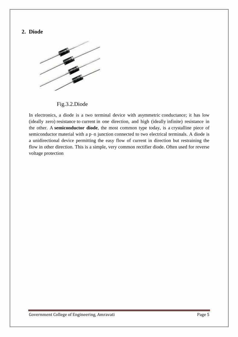
2. Diode
Fig.3.2.Diode
In electronics, a diode is a two terminal device with asymmetric conductance; it has low
(ideally zero) resistance to current in one direction, and high (ideally infinite) resistance in
the other. A semiconductor diode, the most common type today, is a crystalline piece of
semiconductor material with a p–n junction connected to two electrical terminals. A diode is
a unidirectional device permitting the easy flow of current in direction but restraining the
flow in other direction. This is a simple, very common rectifier diode. Often used for reverse
voltage protection

Government College of Engineering, Amravati Page 6
3. Capacitor- (1000 microfarad, 25 V & 100 microfarad, 25 V, 0.1 microfarad)
A capacitor is a passive electronic component consisting of a pair of conductors separated by
a dielectric (insulator). When there is a potential difference (voltage) across the conductors, a
static electric field develops in the dielectric that stores energy and produces a mechanical
force between the conductors. An ideal capacitor is characterized by a single constant value,
capacitance, measured infrareds. This is the ratio of the electric on each conductor to the
potential difference between them.
Fig.3.3.Capacitor

Government College of Engineering, Amravati Page 7
4. IC-555
Fig.3.4.(a).Internal Structure of IC555 Fig.3.4.(b).IC555
The 555 Timer IC is available as an 8-pin metal can, an 8-pin mini DIP (dual-in-package) or
a 14-pin DIP. The pin configuration is shown in the figures.
This IC consists of 23 transistors, 2 diodes and 16 resistors. The use of each pin in the IC is
explained below. The pin numbers used below refers to the 8-pin DIP and 8-pin metal can
packages. These pins are explained in detail, and you will get a better idea after going
through the entire post.
The internal resistors act as a voltage divider network, providing (2/3)Vcc at the non-
inverting terminal of the upper comparator and (1/3)Vcc at the inverting terminal of the lower
comparator. In most applications, the control input is not used, so that the control voltage
equals +(2/3) VCC. Upper comparator has a threshold input (pin 6) and a control input (pin 5).
Output of the upper comparator is applied to set (S) input of the flip-flop. Whenever the
threshold voltage exceeds the control voltage, the upper comparator will set the flip-flop and
its output is high. A high output from the flip-flop when given to the base of the discharge
transistor saturates it and thus discharges the transistor that is connected externally to the
discharge pin 7. The complementary signal out of the flip-flop goes to pin 3, the output. The
output available at pin 3 is low. These conditions will prevail until lower comparator triggers
the flip-flop. Even if the voltage at the threshold input falls below (2/3) VCC, that is upper
comparator cannot cause the flip-flop to change again. It means that the upper comparator
can only force the flip-flop’s output high.To change the output of flip-flop to low, the voltage
at the trigger input must fall below + (1/3) Vcc. When this occurs, lower comparator triggers
the flip-flop, forcing its output low. The low output from the flip-flop turns the discharge
1
2
3
4
8
7
6
5
555
GND
TRIGGER
O/P
VCC
THRESHOLD
CONTOLED VOLTAGE
DISCHARGE
RESET

Government College of Engineering, Amravati Page 8
transistor off and forces the power amplifier to output a high. These conditions will continue
independent of the voltage on the trigger input. Lower comparator can only cause the flip-
flop to output low. From the above discussion it is concluded that for the having low output
from the timer 555, the voltage on the threshold input must exceed the control voltage or +
(2/3) VCC. This also turns the discharge transistor on. To force the output from the timer high,
the voltage on the trigger input must drop below +(1/3) VCC. This turns the discharge
transistor off. A voltage may be applied to the control input to change the levels at which the
switching occurs. When not in use, a 0.01 nano Farad capacitor should be connected between
pin 5 and ground to prevent noise coupled onto this pin from causing false triggering.
Connecting the reset (pin 4) to a logic low will place a high on the output of flip-flop. The
discharge transistor will go on and the power amplifier will output a low. This condition will
continue until reset is taken high. This allows synchronization or resetting of the circuit’s
operation. When not in use, reset should be tied to +VCC.

Government College of Engineering, Amravati Page 9
5.LED
Fig.3.5.LED
A light-emitting diode (LED) is a semiconductor device that emits visible light when an
electric current passes through it. The light is not particularly bright, but inmost LEDs it is
monochromatic, occurring at a single wavelength. The output of an LED can range from red
(at a wavelength of approximately 700 nanometers) to blue-violet (about 400 nanometers).
An LED consists of two elements of processed material called P-type semiconductors and N-
type semiconductors. These two in these elements are placed in direct contact, forming a
region called the P-N junction. In this respect, the LED resembles the most other type diode
types, but there are Important other differences between the light emitting diode and the
normal diodes

Government College of Engineering, Amravati Page 10
6.Variable resistance-220 K, 10 K
Fig3.6.Variable Resister
A variable resistor is a three terminal passive electronic component which implements
electrical resistance as a circuit element. When a voltage V is applied across the terminals of
a resistor, a current I will flow through the resistor in proportion to that voltage. The reciprocal
of the constant of proportionality is known as the resistor R, since, with a given voltage V, a
larger value of R further "resists" the flow of current I . Resistors are common elements of
electrical and electronic circuits .Avariable resistance can used from 0 to it’s maximum value.

Government College of Engineering, Amravati Page 11
7. Transistor- CL 100, BC 457
Fig.3.7. Transistor
Transistor is a semiconductor device used to amplify and switch electronic signals. It is made
of a solid piece of semiconductor material, with at least three terminals for connection to an
external circuit. Transistors are commonly used as electronic switches, for both high power
applications including switched-mode power supplies and low power applications such as
logic gates. A voltage or current applied to one pair of the transistor's terminals changes the
current flowing through another pair of terminals. Because the controlled (output) power can
be much more than the controlling (input) power, the transistor provides amplification of a
signal. When used operates within its "Active" region and the linear part of the output
characteristics curves are used. However, both the NPN & PNP type bipolar transistors can
be made to operate as an "ON/OFF" type solid state switch for controlling high power
devices.

Government College of Engineering, Amravati Page 12
8. Comparator IC (LM324)
Fig.3.8.Comparator
These devices consist of four independent high-gain frequency-compensated operational
amplifiers that are designed specifically to operate from a single supply over a wide range of
voltages .Operation from split supplies also is possible when the difference between the two
supplies is 3 V to 30 V (for the LM2902, 3 V to 26 V) and VCC is at least 1.5 V more
positive than the input common-mode voltage. The low supply-current drain is independent
of the magnitude of the supply voltage. Applications include transducer amplifiers, dc
amplification blocks, and all the conventional operational-amplifier circuits that now can be
more easily implemented in single-supply-voltage systems.
1
2
3
4
5
6
7
14
13
12
11
10
9
8
LM324
OUTPUT
OUTPUT OUTPUT
+INPUT
+INPUT+INPUT
+INPUT
-INPUT -INPUT
-INPUT -INPUT
+VCC -VCC
OUTPUT

Government College of Engineering, Amravati Page 13
9. Relay- Double port (DPDT), single pole (SPST)
Fig.3.9. DPDT Relay
A relay is an electrically operated switch Many relays use an electromagnet to mechanically
operate a switch, but other operating principles are also used, such as solid-state relays.
Relays are used where it is necessary to control a circuit by a low-power signal (with
complete electrical isolation between control and controlled circuits), or where several
circuits must be controlled by one signal.
Basic design and operation
A simple electromagnetic relay consists of a coil of wire wrapped around a soft iron core an
iron yoke which provides a low reluctance path for magnetic flux, a movable iron armature
and one or more sets of contacts (there are two in the relay pictured). The armature is hinged
to the yoke and mechanically linked to one or more sets of moving contacts. It is held in
place by a spring so that when the relay is de-energized there is an air gap in the magnetic
circuit.When an electric current is passed through the coil it generates a magnetic field that
activates the armature and the consequent movement of the movable contact either makes or
breaks (depending upon construction) a connection with a fixed contact. If the set of contacts
was closed when the relay was de-energized, then the movement opens the contacts and
breaks the connection, and vice versa if the contacts were open. When the current to the coil
is switched off, the armature is returned by a force, approximately half as strong as the
magnetic force, to its relaxed position.

Government College of Engineering, Amravati Page 14
Pole and throw
Since relays are switches the terminology applied to switches is also applied to relays; a relay
switches one or more poles, each of whose contacts can be thrown by energizing the coil in
one of three ways
• Normally-open (NO) contacts connect the circuit when the relay is activated; the circuit is
disconnected when the relay is inactive. It is also called aForm A contact or "make"
contact. NO contacts may also be distinguished as "early-make" or NOEM, which means that
the contacts close before the button or switch is fully engaged.
• Normally-closed (NC) contacts disconnect the circuit when the relay is activated; the circuit
is connected when the relay is inactive. It is also called a Form B contact or "break"
contact. NC contacts may also be distinguished as "late-break" or NCLB, which means that
the contacts stay closed until the button or switch is fully disengaged.
• Change-over (CO), or double-throw (DT), contacts control two circuits: one normally-open
contact and one normally-closed contact with a common terminal. It is also called a Form
C contact or "transfer" contact ("break before make"). If this type of contact utilizes “make
before break" functionality, then it is called a Form D contact.
The following designations are commonly encountered:
• SPST – Single Pole Single Throw. These have two terminals which can be connected or
disconnected. Including two for the coil, such a relay has four terminals in total. It is
ambiguous whether the pole is normally open or normally closed. The terminology "SPNO"
and "SPNC" is sometimes used to resolve the ambiguity
• SPDT – Single Pole Double Throw. A common terminal connects to either of two others.
Including two for the coil, such a relay has five terminals in total.
• DPST – Double Pole Single Throw. These have two pairs of terminals. Equivalent to two
SPST switches or relays actuated by a single coil. Including two for the coil, such a relay has
six terminals in total. The poles may be Form A or Form B (or one of each).
• DPDT – Double Pole Double Throw. These have two rows of change-over terminals.
Equivalent to two SPDT switches or relays actuated by a single coil. Such a relay has eight
terminals, including the coil.

Government College of Engineering, Amravati Page 15
Applications
Relays are used for:
• Logic functions. For example, the boolean AND function is realised by connecting normally
open relay contacts in series, the OR function by connecting normally open contacts in
parallel. The change-over or Form C contacts perform the XOR (exclusive or) function.
Similar functions for NAND and NOR are accomplished using normally closed contacts.
The Ladder programming language is often used for designing relay logic networks.
• Switching to a standby power supply.
Government College of Engineering, Amravati Page 16
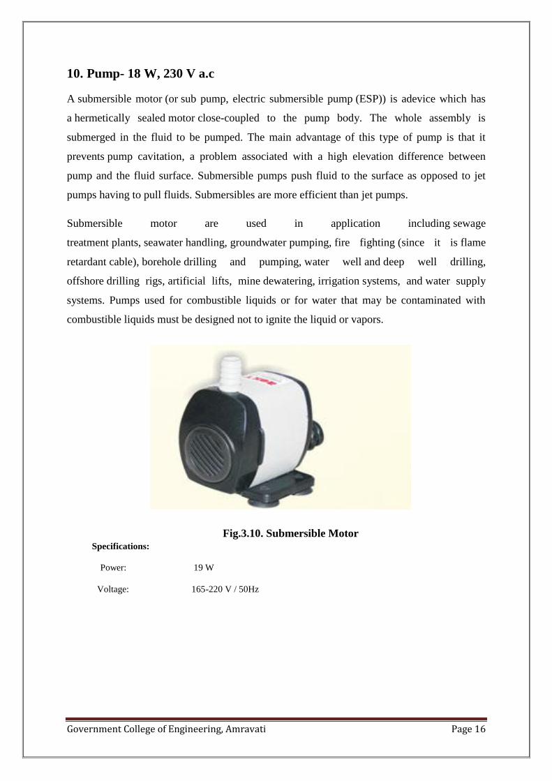
10. Pump- 18 W, 230 V a.c
A submersible motor (or sub pump, electric submersible pump (ESP)) is adevice which has
a hermetically sealed motor close-coupled to the pump body. The whole assembly is
submerged in the fluid to be pumped. The main advantage of this type of pump is that it
prevents pump cavitation, a problem associated with a high elevation difference between
pump and the fluid surface. Submersible pumps push fluid to the surface as opposed to jet
pumps having to pull fluids. Submersibles are more efficient than jet pumps.
Submersible motor are used in application including sewage
treatment plants, seawater handling, groundwater pumping, fire fighting (since it is flame
retardant cable), borehole drilling and pumping, water well and deep well drilling,
offshore drilling rigs, artificial lifts, mine dewatering, irrigation systems, and water supply
systems. Pumps used for combustible liquids or for water that may be contaminated with
combustible liquids must be designed not to ignite the liquid or vapors.
Fig.3.10. Submersible Motor Specifications:
Power: 19 W
Voltage: 165-220 V / 50Hz

Government College of Engineering, Amravati Page 17
Chapter 4. DESCRIPTION OF CIRCUIT
Power Supply
Water Level Indicator
Controlling Circuit
Soil Moisture Detector (Humidity Sensor)
POWER SUPPLY:
A. Circuit Diagram:
Fig.4.1.(a).Rectifier circuit
Fig.4.1.(b).Rectifier circuit waveform
B. Working:
In a rectifier, centre tapped transformer and two diodes forms a full wave rectifier
that allows both half cycles of AC waveform to contribute direct current(DC) making it
smoother than half wave rectifier. Output from diodes gives pulsating DC. To make it into
pure DC form we use capacitor filter across the output.LED used in circuit indicate that
power supply is in good condition.

Government College of Engineering, Amravati Page 18
WATER LEVEL INDICATOR:
A. Circuit Diagram:
Fig.4.2.Water level indicator
B. Working:
IC 555 is used in the monostable mode for making water level indicator. Circuit is made
as shown in figure. In the circuit, the value of R and C decide the time constant. As we require
instant response to input, values of R and C are taken small. i.e. 10 K-ohm and 100 microfarad.
To trigger, pin Vcc is connected through a variable resistor and to the same pin we connect the
water (as a resistor) and give it to ground.
As we know the value of water resistor is from 80 K to 100 K. We set the pot having more
resistor than 100 K-ohm. When the terminal which is used for indication is in the air, it acts as
infinite resistance between ground terminal and pin 2. So, current flowing through the circuit is
due to Vcc as it follows low resistance path and pin is triggered by Vcc i.e. logic1 and the output
of circuit is logic 0. When the indicating terminal is in the water, resistance between indicating
terminal and ground is about 80K-ohm to 100 K-ohm. It follows the low resistance path as
resistance between trigger pin and Vcc is greater than resistance between trigger pin and ground.
Ground appears at trigger pin. Hence, input to the pin 2 is logic 0 and the output of circuit is logic
1.
As IC 555 is used in monostable mode it acts as inverter. When it is triggered by logic 0,circuit
gives output as one i.e.,when indicating signal is in contact with water, output is logic 1.
i/p from water
vcc
GND
1
2
3
4
8
7
6
5
555
0.01µF
220Kohm
100µF25V

Government College of Engineering, Amravati Page 19
CONTROLLING CIRCUIT:
A. Circuit Diagram:
Fig.4.3.Controlling Circuit
B. Working:
It consist of four NPN power transistors (CL 100), diodes and DPDT relay. The components
are connected as per the circuit diagram.
When the signal to the base of transistor Q1 is logic 1, then transistor Q1 will get ON and
Vcc occurs at base of transistor Q3 which make Q3 ON and Vcc is applied through transistor
which occur at collector of Q4.
When input to the base of Q2 is also logic 1 then it gets turned ON and Vcc is applied at the
collector of Q2 and it occurs at base of Q4 so that it also gets turned ON. As transistor Q3
and Q4 get turned ON because the inputs given to base of Q1 and Q2 is at logic 1 and
current flows through the coil of DPDT relay which is sufficient to turn it ON. As relay gets
turned ON, none of the terminal is closed and hence the controlled output is logic 1.
As relay gets turnedON holding circuit starts and it provides input to the transistor Q3.Now it
is in ON state. So its output is independent of the input to the base of Q1.
If input to the Q1 is zero then transistor Q3 is in ON state. But when input to the Q2 is logic
0, Q2 becomes OFF and input to Q4 is logic 0 which makes it OFF. No current flows through
DPDT relay and relay becomes ON which disconnects the holding circuit. Now turning ON
the relay depends on input to the transistor Q1.
When both inputs to transistors Q1 and Q2 becomes one rely turns ON and operates as above.
i/p from waterlevel indicator
i/p from waterlevel indicator
vcc
Q1
Q2
Q3
Q4

Government College of Engineering, Amravati Page 20
SOIL MOISTURE DETECTOR (HUMIDITY SENSOR)
A. Circuit Diagram:
Fig.4.4.Soil Moisture Detector circuit
B. Working:
It is comparator IC. It has four operational amplifier. When we apply positive voltage with
respect to ground then it gives output as Vcc. If difference between positive & negative is
negative, it gives -Vcc.
When positive input is in wet soil then it is connected to ground. Ground and no o/p gives
negative voltage difference and hence o/p is at logic negative i.e. at logic0. When it is in dry
soil, the difference is positive and output is at logic1 i.e., we get output as Vcc. All the four
outputs are connected to OR gate(constructed with help of transistors). When all input is in
wet soil resultant output is at logic 0 and if any of input is in dry soil output is at logic 1.
1
2
3
4
5
6
7
14
13
12
11
10
9
8
LM324
vcc
O/P
i/pfromsoil
vcci/p
fromsoil
i/pfromsoil
i/pfromsoil

Government College of Engineering, Amravati Page 21
COMBINED CIRCUIT:
Fig.4.5.Combined circuit
A. Working: According to the water available we set the position of our water level indicator. When we
extract water from well by pump, the rate of extraction of water is greater than rise of water in well.
When we turn ON thepump, after some time water level gets lowered and reaches to the bottom
of well but pump is still running. As no any arrangement is made for cooling of pump, it gets heated
and it may burn out and continuous losses occurs.
In this system, two sensors are used. One at upper level and other at lower level. When both
indicators are in water, water indicator gives output out of which one is the input to controller circuit.
When both inputs to the controller are logic 1 then one transistor turns on and it means output of
circuit is logic 1.

Government College of Engineering, Amravati Page 22
After some time water level gets lowered which means upper indicator is in the air. But due to
the holding circuit used output will remain one when bottom indicator will be in air.When bottom
indicator is in air, it means there is no water in the well and output of controller is zero which turns off
the pump automatically.
When again the water level in the well rises bottom indicator will be in water so it will recognise
and gives output as one. So air relay becomes off and output of controller is zero. When water reaches
to level of upper indicator both the inputs to controller becomes one which gives its output also as
one. This turns ON the pump and operation of circuit by indicator is done sequentially.
Due to the continuous operation of pump soil becomes wet so there will be no meaning of
providing water to field because it leads to salinity of soil, wasting of electricity also. In order to
overcome this issue we use soil moisture indicator circuit to control the operation of pump. When all
terminals of indicator are in soil then output of each indicator is one. These all inputs are connected
through OR gate hence so there combined output will be one. When any of the terminals is in the dry
soil then its output will be one and pump will provide water to that part of the plant.
When all terminals are in wet soil then output of each cell is zero & combined output will also be
zero which results in stopping the operation of pump. So when there is no need then pump will get
turn OFF.
If both conditions are satisfying i.e. availability of water in well and necessity of water to field
input to and gate becomes one pump will get turn on. If any of the condition doesn’t get satisfied
motor will be in OFF state. It means either there is no water available or no need of water so pump
gets turn OFF.

Government College of Engineering, Amravati Page 23
Chapter 5. COST AND ACTUAL IMPLEMENTATION
To implement this project only some replacement should be taken out and we can implement the
project as it is. Only we have to replace SPST relay by contactor (relay) of higher rating (which is
used in star-delta starter).The cost of contactor is near about 900/- only.
As we keep terminals of indicator in soil and water due to corrosion and chemical reaction the contact
resistance is increase. To avoid this problem we can use stainless steel spoon at the indicator terminal,
as stainless steel is free from corrosion. Only there is need to wash it after specific interval of time.
Sr.
No.
Component Price
1 Transformer
45
2 Diodes
2
3 Capacitor
20
4 IC-555
10
5 IC LM 324
8
6
LED 5
7 Pot
15
8
Transistor 60
9
Relay 35
10 Contactor
900
11 Dot matrix PCB
50
12 Stainless steel spoon
50
13 Other 100
Total
1300
Therefore, for actual implementation of project estimated cost is 1300/- rupees only

Government College of Engineering, Amravati Page 24
Chapter 6. ADVANTAGES AND LIMITATIONS
Advantages
1. There is no need of operator for irrigation as all things are done automatically so labour cost
is reduced.
2. Installation cost is reduced.
3. There is no need of network like in GSM based auto irrigation.
4. Dry running of pump is avoided so there is rare chance of damage to pump.
5. As the pump runs according to the requirement and availability only, electricity is saved.
6. Wastage of water avoided.
7. As use of water is optimum, it avoids soil from become infertile.
8. If any problem arises then pump can operate manually by simply turning ON the ICTP .
Limitations
As the contact resistance of indicator lead is increased by keeping it in soil and water, the accuracy
may be reduced after a long time. So there is need to wash the lead after specific interval of time.

Government College of Engineering, Amravati Page 25
Chapter 7. FUTURE SCOPE
In this project we have dealt with the problems of automatic turning ON and OFF of the
pumps according to the availability of water supply and supply of appropriate water to the
soil. In future we can expand this project to solve the further irrigation problems like single
phasing and heating of pump by the use of single phasing preventing circuit and heat sensors.
In the above circuit, we have used transistor logic for turning processes and since transistors
are unreliable, we can replace it by the use of relay logic.

Government College of Engineering, Amravati Page 26
Chapter 8. CONCLUSION
By the use of this project, the farmer now does not follow a schedule for turning ON and OFF
of pumps. Also no electricity will be wasted due to running of pumps in dry conditions
resulting into damage of pumps. Excessive irrigation which causes the soil to deteriorate can
be prevented by the use of this project. In future each and every farmer might wake up in
need of such a system, therefore the proposed applications which targeted an automatic
irrigation system with minimal cost, time and human interaction was studied.

Government College of Engineering, Amravati Page 27
Chapter 9. REFERENCE
1. Digital Electronics –R.P.Jain
2. Power Electronics –P.S.Bhimbhra
3. www.circuitstoday.com
Copyright © 2022 FDOKUMEN