ON ADAPTIVE INTELLIGENT WELDING - LUTPub
177
Emmanuel Afrane Gyasi ON ADAPTIVE INTELLIGENT WELDING: TECHNIQUE FEASIBILITY IN WELD QUALITY ASSURANCE FOR ADVANCED STEELS Acta Universitatis Lappeenrantaensis 805
-
Upload
khangminh22 -
Category
Documents
-
view
0 -
download
0
Transcript of ON ADAPTIVE INTELLIGENT WELDING - LUTPub
Emmanuel Afrane Gyasi
ON ADAPTIVE INTELLIGENT WELDING: TECHNIQUE FEASIBILITY IN WELD QUALITY ASSURANCE FOR ADVANCED STEELS
Acta Universitatis Lappeenrantaensis
805

Emmanuel Afrane Gyasi
ON ADAPTIVE INTELLIGENT WELDING: TECHNIQUE FEASIBILITY IN WELD QUALITY ASSURANCE FOR ADVANCED STEELS
Acta Universitatis Lappeenrantaensis 805
Thesis for the degree of Doctor of Science (Technology) to be presented with due permission for public examination and criticism in the lecture hall 2305 at Lappeenranta University of Technology, Lappeenranta, Finland, on the 28th
of August, 2018, at noon.

Supervisors Associate Professor, Docent Paul Kah
LUT School of Energy Systems
Lappeenranta University of Technology
Finland
Professor Heikki Handroos
LUT School of Energy Systems
Lappeenranta University of Technology
Finland
Reviewers Professor Suck-Joo Na
Department of Mechanical Engineering
Korea Advanced Institute of Science and Technology
South Korea
Professor Victor A. Karkhin
Department of Mechanical Engineering
Peter the Great St. Petersburg Polytechnic University
Russia
Opponents Professor Suck-Joo Na
Department of Mechanical Engineering
Korea Advanced Institute of Science and Technology
South Korea
Professor Victor A. Karkhin
Department of Mechanical Engineering
Peter the Great St. Petersburg Polytechnic University
Russia
ISBN 978-952-335-251-3
ISBN 978-952-335-252-0 (PDF)
ISSN-L 1456-4491
ISSN 1456-4491
Lappeenrannan teknillinen yliopisto
Yliopistopaino 2018

Abstract
Emmanuel Afrane Gyasi
On adaptive intelligent welding: technique feasibility in weld quality assurance for
advanced steels
Lappeenranta 2018
100 pages
Acta Universitatis Lappeenrantaensis 805
Diss. Lappeenranta University of Technology
ISBN 978-952-335-251-3, ISBN 978-952-335-252-0 (PDF), ISSN-L 1456-4491, ISSN
1456-4491
The welding industry has a need to utilize lightweight steels in welded applications while
maintaining acceptable weld quality. This goal can be achieved through effective quality
assurance, efficient weld parameter decision-making systems, and careful choice of steel
grades. Consequently, there is a need for: i) knowledge enabling manufacturers to select
appropriate lightweight material to meet the requirement for reduced structural weight
and attain cost reduction in welding manufacturing; and ii) new ways to assure weld
quality in real-time, ideally with welding systems that are self-adjusting and able to
eliminate welding flaws during welding. Concurrent with this evolution towards lighter
structures, the next phase in modern manufacturing, Industry 4.0, is also driving welding
industries to digitization of manufacturing using advanced welding technologies. The
Industry 4.0 concept aims to harness emerging digital technologies for enhanced quality,
connectivity, productivity, and environmental and economic gain via improved reliability
in manufacturing and production. Greater integration of evolving technologies in
automation, digitization and artificial intelligence (AI) are required in welding
manufacturing to realize a sustainable future industry.
The objectives of this thesis are to provide an overview of weld integrity aspects of
advanced steels, that is, high strength steels (HSS) and ultra high strength steels (UHSS),
and through experimental study to explore the applicability of adaptive intelligent robotic
gas metal arc welding (GMAW) of UHSS for structural applications. Additionally, the
study aims to utilize the findings from experimental work in the design of a new weld
quality assurance model based on adaptive intelligence. This aspect is grounded on the
concept of Industry 4.0 and the “big data” involved in systems integration processes
(automation, robotics, sensory, monitoring and artificial intelligent systems).
The thesis is an article-based study comprising the outcome of five research articles.
Research methods used include both review of previous work and experimental study.
Review of the weldability of HSS and UHSS showed that these steels have high
susceptibility to heat affected zone (HAZ) softening when they are welded at elevated
temperatures and with imprecisely controlled heat input. Additionally, a risk of cold
cracking and a propensity to weld integrity problems arises when the steels are welded
with filler materials having high hydrogen content and varying strength. The experimental
studies indicated the feasibility of effectively welding these steels with accurately
modelled and controlled welding heat conditions. The welding of direct-quenched UHSS

S960QC material in fillet joint configurations in different welding positions with an
adaptive intelligence welding system demonstrated the possibility of real-time process
monitoring, process outcome prediction, and control of welding parameters and variables
in robot welding with the aim of achieving desired weld quality. The behaviour of welding
parameter control and adaptation and their effects correlate with the consequential
changes in the macrostructure, mechanical properties and microstructure of the
weldments.
A new weld quality assurance model based on adaptive intelligence systems is examined
and presented with detailed steps. The model aims to assist welding companies, large and
small and medium-sized enterprises (SMEs), in their decision-making, and to contribute
to efforts to integrate and advance the implementation of adaptive welding systems in
manufacturing and production networks. The new weld quality assurance model
facilitates digitization of weld quality and quality assurance processes to improve weld
quality, eliminate or reduce already at the commissioning stage weldments with defects,
maintain a digital history of the welding operation for optimization and development
purposes, reduce rework, trace weld defects digitally and in real-time, and define and
approve welding procedure specification (WPS) in digital formats. In addition to the
fundamental aim of weld quality assurance, additional benefits for welding companies
include opportunities to network with other robot cells in other companies and firms and
synchronize adaptive welding systems on a global level for common welding production
throughput.
Keywords: High strength steels, ultra high strength steels, robotic GMAW process,
adaptive welding, artificial neural network, weld quality assurance, intelligent systems.

Preface
Having the privilege to do doctoral studies is the opportunity of a lifetime. Such work
enables continuous personal growth and the development of knowledge in a specific field
of endeavour. It helps broaden horizons and gives a platform to connect with other
experts, which might otherwise not be possible. A doctoral degree brings the holder
increased status in the area of specialization, as a result of improved expertise, but also
brings the obligation to contribute to society, industry and the world as a whole. My
journey through doctoral study has been an eye opener for both personal and career
development. It has provided the basis for my understanding of entrepreneurial thinking,
which is informed by the requirement for effective and innovative decision-making, and
sustainable value creation. Throughout this journey, I have endeavoured to share my
knowledge and contribute in diverse ways. In Finland, I have acted as a bridge for the
transfer of ideas on technology-related business between Finland and Ghana. In Ghana, I
have endeavoured to contribute by helping to develop welding training programs in local
companies and educational institutions. As the founder of a non-governmental and not-
for-profit organization, my vision has been to promote and accelerate the development of
welding training and learning in West Africa, and to advocate for greater appreciation in
the region of the importance of health, safety and environmental issues in welding. The
organization aims to familiarize about 1000 new welders, many of them women, with
internationally established welding norms and expose them to international welding
practices. My doctoral studies are a collection of experiences from both the academic and
the industrial world. My industrial experience stared in the latter part of 2014 when I had
the opportunity to do a doctoral internship in Canada. I worked as a structural welder in
a fabrication company producing welded structures for the oil and gas industry.
Conventional steels were mostly used in the fabrication of the oil and gas production
units, sand filtration units, etc. As most of the oil production units were mounted on
trailers, the need to use lightweight steels to reduce weight on the trailers and to minimize
fuel consumption became a concern. Having become aware of the importance of this
issue, I was motivated to investigate lightweight steels as a part of my doctoral studies.
Returning to Finland in 2015, I made several visits to local fabrication companies to
identify the extent of the need for greater use of lightweight steels in their product
manufacturing. Similar concerns to their Canadian colleagues were expressed. During the
latter part of 2015, I had the opportunity to use industrial robots in welding of lightweight
steel plates. During this work, I identified some drawbacks in present-day industrial
robots, in particular the inability of current welding robots to adapt in real-time to changes
in the welding environment. Repeated precision errors sometimes occurred, which led to
the production of bad quality welds. My interest in adaptive welding systems encouraged
me to maintain and strengthen my contacts with original equipment manufacturers
(OEM) of welding equipment, robots, lasers and sensors. I then had the privilege to work
for an adaptive welding project at the Laboratory of Welding Technology, Lappeenranta
University of Technology (LUT) in mid-2017 and the Manufacturing 4.0 project of the
Laboratory of Intelligent Machines in 2018.
I remain grateful and thankful to you all who encouraged and helped me travel this far.


Acknowledgements
My profound thanks go to my supervisor, Associate Professor Paul Kah, for his
encouragement and sincere support throughout this work. I call you “Prof” because of
your selfless attitude, professionalism in research, patient and attentive attitude,
international outlook, and willingness to help regardless of time. Thanks for devoting
your precious time to my concerns and my research work. You shared ideas with me at
all times, and sometimes even at dawn. Can any supervisor be as motivating as you are?
The relationship we have built over these years has become as hard as steel, and our hearts
are welded together. I have learned so much from you “Prof”. I am grateful you took me
as one of your protégés. Truly, mentorship is your flagship. “Merci beaucoup”.
My sincere thanks go to my second supervisor, Professor Heikki Handroos, whose
financial support has helped me to complete my studies. Dear Professor Heikki, I am very
grateful to you. I am very glad for the trust we are building together. “Kiitos paljon”.
Special thanks to Peter Jones. Sir, you have played an important role as an internal
reviewer in many ways. Your comments and English language checks on my scripts are
revealing and profound. Also, thanks to the external reviewers of this work, Professor
Suck-Joo Na and Professor Victor A. Karkhin. I am very grateful that you agreed to
review my work and thank you for taking the time to help me complete my apprenticeship
as a researcher.
I would like to thank Professor Emeritus Jukka Martikainen for his support during the
early years of my research. My thanks go to all the staff of the Laboratory of Welding
Technology and my colleagues from the Department of Mechanical Engineering, whose
assistance made this work a reality. I would like to express my gratitude to Esa Hiltunen,
Docent Huapeng Wu, Dr. Markku Pirinen, Raimo Suoranta and Dr. Juho Ratava. To my
research colleagues and friends, Dr. Eric Mvola Belinga and Dr. Pavel Layus, I have
learnt from you how to be patient in research. I say thanks for this and for the support you
have given me in many other ways. Many thanks to Sakari Penttilä, François Njock
Bayock and Charles Nutakor for their support.
Special thanks to my friend Martin Appiah Kwame Kesse for his encouragement and
support throughout my journey on this work. Kwame, we have been in this struggle
together, in the snow, rain and sunshine. It seems that I am nearing the end of this
particular journey, but your destination is still ahead. I will not leave you to travel alone.
Also, special thanks to my brother Enoch Afrane Gyasi and to my long standing friend
Dennis Mireku Sasu for their encouragement and unflinching support.
To Antero Jernberg from the Lappeenranta Employment and Economic Development
Office (TE Office), thanks so much for your encouragement and support. Thanks to Jukka
Vasara from Sampo Saimaa Adult Vocational College and Jouni Verhelä for taking me
through practical training in welding and robotics respectively. Also, thanks to Markus
Melander, Ilkka Rautianen, Hannu Ylisiurua and Jarmo Ihalainen for their
encouragement.

To my fathers – Mr. Peter Afrane Gyasi (deceased), Mr. John Ofori Gyasi, Mr. Kwasi
Gyamfi Gyasi, Mr. Kojo Anyimadu, and Mr. Kofi Karikari Gyasi. I say thank you all for
your fatherly love and contribution in my life.
I would like to say a big thanks to my Mother, Susuana Baidoo, for her love, care and
constant encouragement on my journey in this work. Oh “Mama Suzzy”, words cannot
describe my appreciation to you. This hard-earned piece of work is for you.
To my beloved wife, Johanna Mustonen-Gyasi, and my beautiful daughters, Jenni Riina
Susuana Gyasi and Adiella Petra Alina Gyasi, I say special thanks to you all. You are the
last on my list but you are also the first – the foundation and source of energy for this
work. Without your support and love, I would not have made it this far. To God be the
glory. God bless you all.
Emmanuel Afrane Gyasi
August 2018
Lappeenranta, Finland

Dedication
To my mother Susuana Baidoo
And
To the entire Gyasi & Mustonen family


Contents
Abstract
Preface
Acknowledgements
Contents
List of publications 13
Nomenclature 14
1 Introduction 17 1.1 Research Background .............................................................................. 18
1.1.1 Usability of HSS and UHSS for welded joints ........................... 19 1.1.2 Adaptive welding using industrial robots ................................... 22
1.2 Motivation of the study ........................................................................... 23 1.3 Research objectives ................................................................................. 23 1.4 Research questions .................................................................................. 23 1.5 Overview of the work .............................................................................. 24 1.6 Impact on society and the environment ................................................... 25 1.7 Limitation and scope ............................................................................... 26 1.8 Research hypothesis ................................................................................ 27
2 State of the art of adaptive intelligent GMAW 29 2.1 Gas Metal Arc Welding (GMAW) process ............................................. 29
2.1.1 Heat transfer and fluid flow ........................................................ 31 2.1.2 Relative effects on weld quality of fillet joints ........................... 34 2.1.3 Automating the manual operation of the GMAW process ......... 39
2.2 Sensing and monitoring of the robotic GMAW process ......................... 40 2.2.1 Sensing technological parameters ............................................... 40 2.2.2 Sensing geometrical parameters .................................................. 41 2.2.3 Monitoring of process variables and parameters ........................ 43
2.3 Modelling the robotic GMAW process for control purposes .................. 45 2.3.1 Geometrical and theoretical modelling approaches .................... 45 2.3.2 Welding process controllers ........................................................ 46
2.4 Artificial intelligence modelling and control of robotic GMAW ............ 47
2.4.1 Artificial neural network (ANN) ................................................. 48 2.4.2 Intelligent control using ANN ..................................................... 50
3 Research methods and summary of findings 53 3.1 Review of previous studies ...................................................................... 53
3.1.1 Publication I ................................................................................ 53

3.1.2 Publication II ............................................................................... 55 3.1.3 Publication V ............................................................................... 56
3.2 Experimental study .................................................................................. 57 3.2.1 Publication III ............................................................................. 59 3.2.2 Publication IV ............................................................................. 63
4 WQA model based on AIS 73 4.1 Identification and selection of system hardware ..................................... 74 4.2 System integration protocols ................................................................... 75 4.3 The AIS based WQA model .................................................................... 77
5 Future research 83 5.1 Other research directions ......................................................................... 83
6 Conclusions 85
References 89
Appendix
Publications

13
List of publications
This thesis is based on the following scientific publications. The rights have been granted
by the publishers to include the publications in the dissertation.
I. Gyasi, E.A., Kah, P. (2016). Structural integrity analysis of the usability of High
Strength Steels (HSS). Reviews on Advanced Materials Science, 46, pp. 39-52.
II. Gyasi, E.A., Kah, P., Wu, H., Kesse, M.A. (2017). Modelling of an artificial
intelligence system to predict structural integrity in robotic GMAW of UHSS fillet
welded joints. The International Journal of Advanced Manufacturing Technology,
93 (1-4), pp. 1139-1155.
III. Gyasi, E.A., Kah, P., Ratava, J., Kesse, M.A., Hiltunen, E. (2017). Study of
adaptive automated GMAW process for full penetration fillet welds in offshore
steel structures. Proceedings of the Twenty-seventh (2017) International Ocean
and Polar Engineering Conference, San Francisco, CA, USA, June 25-30, pp.
290-297.
IV. Gyasi, E.A., Kah, P., Handroos, H., Layus, P., Lin, S (2018). Adaptive welding
of S960QC UHSS for Arctic structural applications. International Review of
Mechanical Engineering, 12 (4).
V. Gyasi, E.A., Pirinen, M., Martikainen, J., Nallikari, M (2015). Transforming
Arctic welding with Finnish technological know-how. Canadian Welding
Association (CWA) Conference and the International Institute of Welding (IIW)
International Congress, Vancouver, Canada, September 28-October 1, 2014.
Author’s contribution
Emmanuel Afrane Gyasi is the principal author and investigator in papers I – V. The ideas
and experiments for all the papers were generated and constructed by the author. The co-
authors assisted in performing the experiments and evaluation of the findings as well as
reviewing and improving the papers.
Other scientific publications
Layus, P., Kah, P., Kesse, M., Gyasi, E.A. (2017). Submerged arc welding
productivity in welding thick high strength steel plates used for Arctic
applications. Proceedings of the Twenty-seventh (2017) International Ocean and
Polar Engineering Conference, San Francisco, USA, June 25-30, pp. 92-98.
Kesse, M., Gyasi, E.A., Kah, P. (2017). Usability of laser-TIG hybrid welding
processes. Proceedings of the Twenty-seventh (2017) International Ocean and
Polar Engineering Conference, San Francisco, USA, June 25-30, pp. 42-49.
Yang, X., Kah, P., Gyasi, E.A., Martikainen, J. (2016). Risk management system
and execution in welding for offshore and coastal constructions. Proceedings of
the Twenty-sixth (2016) ISOPE Conference, Rhodes, Greece, July 2, pp. 92-98.

Nomenclature 14
Nomenclature
In the present work, variables and constants are denoted using slanted type and
abbreviations are denoted using normal type.
Latin alphabet
A area m2
E arc energy kJ/mm
I arc current A
U arc voltage V
v welding speed mm/s
Q heat input kJ/mm
cp specific heat capacity at constant pressure J/(kgK)
cv specific heat capacity at constant volume J/(kgK)
d diameter m
F force vector N
f frequency Hz
g acceleration due to gravity m/s2
h heat transfer coefficient W/(m2K)
j flux vector m/s
L characteristic length m
l length m
m mass kg
p pressure Pa
q heat flux W/m2
r radius m
T temperature K
t time s
Uw material moving speed kg/s
V volume m3
v velocity magnitude m/s
v velocity vector m/s
x x-coordinate (width) m
y y-coordinate (depth) m
z z-coordinate (height) m
Greek alphabet
α alfa
β beta
γ gamma
Δ capital delta
δ delta
ε emissivity
Nomenclature 15
η Arc efficiency
θ theta
ι iota
κ kappa
Λ capital lambda
λ lambda
μ mu
π pi = 3.14159...
ρ density of metal
Σ capital sigma
σ sigma
τ tau
υ upsilon
ϕ phi variant
Ø oh with stroke
φ phi
χ chi
ψ psi
Ω capital omega
Dimensionless numbers
Gr Grashof number
Pe Peclet number
Fr Froude number
Rm Reynolds number
Ma Surface tension Reynolds number
Abbreviations
AC Alternating Current
AHP Analytical Hierarchy Process
AI Artificial Intelligence
ANFIS Adaptive Neuro-Fuzzy Inference System
ANN Artificial Neural Network
API Application Programming Interface
BM Base Metal
BOM Bill of Materials
BP Back Propagation
BSE Back Scattered Electron
CAD Computer Aided Design
CAM Computer Aided Manufacturing
CCD Charge-Coupled Device
CEV Carbon Equivalence
CFD Computational Fluid Dymanics

Nomenclature 16
CHAZ Coarsed Grained Heat Affected Zone
CMOS Complimentary Metal-Oxide Semiconductor
CTWD Contact-To-Work-Distance
DCEN Direct Current Electrode Negative
DCEP Direct Current Electrode Positive
EDS Energy-Dispersive Spectroscopy
FCAW Flux Cored Arc Welding
GA Genetic Algorithm
GMAW Gas Metal Arc Welding
GTAW Gas Tungsten Arc Welding
HAZ Heat Affected Zone
HD Hydrogen Deuteride
HMI Human and Machines Interface
HRC Human Robot Collaboration
HSS High Strength Steel
HV Vickers Hardness
IP Internet Protocol
IRT Infrared Thermography
ISO International Organization for Standardization
MAG Active Gas Metal
MIG Inert Gas Metal
MLP Multi-Layer Perceptron
OEM Original Equipment Manufacturer
QC Direct Quenched
QT Quenched and Tempered
PA Horizontal Flat Welding Position
PB Horizontal Welding Position
PDM Product Data Management
PID Proportional, Integral and Derivation
PSD Power Spectral Density
PSO Particle Swarm Optimization
RNN Recurrent Neural Network
RPC Remote Procedure Call
SAW Submerged Arc Welding
SEM Scanning Electron Microscopy
SMAW Shielded Metal Arc Welding
SME Small and Medium-sized Enterprices
TMCP Thermo-mechanical Controlled Process
TPS Thermo Profile Sensor
UHSS Ultra High Strength Steel
UTS Ultimate Tensile Strength
WM Weld Metal
WQA Welding Quality Assurance
WPS Welding Procedure Specification

17
1 Introduction
This doctoral thesis describes research that was completed in the Laboratory of Welding
Technology of Lappeenranta University of Technology as a part of efforts to contribute
to expanding knowledge on adaptive intelligent welding of advanced steels (high strength
steels and ultra high strength steels), paying critical attention to the techniques,
applications and weld quality assurance issues involved.
This work has received support from Academy of Finland grants for Lappeenranta
University of Technology, the Laboratory of Welding Technology project ‘Monitoring
and Modelling of Advanced Adaptive Welding Process Systems for Ultra High Strength
Steel (UHSS), and Laboratory of Intelligent Machines project “Manufacturing 4.0 –
Strategies for Technological, Economical, Educational and Social Policy Adoption.
The research methods used in this work are in two parts: review of previous studies as the
first part and empirical study as the second part. Review of previous studies on the
usability of high strength steels and ultra high strength steels, especially as regards
welding conditions is performed. The challenges associated with welding of these
advanced steels, in particular UHSS material, are noted. In line with the overall objective
of the work of devising a holistic welding quality assurance method to help mitigate the
weldability challenges of these advanced steels, the applicability of adaptive welding
systems comprising sensors, monitoring devices and an artificial intelligence approach
with industrial robots is investigated. The concept of Industry 4.0 is briefly presented to
provide the context of the need to use adaptive welding systems in modern factories and
to draw attention to trends in modern manufacturing.
The introductory section to this thesis is structured as follows: research background,
motivation of the study, research objectives, research questions, overview of the thesis,
impact of the work on society and the environment, limitation and scope of the work, and
finally the research hypothesis.
This doctoral thesis is valuable for academia and industry as it provides a comprehensive
study of the subject of adaptive automated welding systems and artificial intelligence for
weld quality prediction, control and assurance when welding advanced steels for
structural applications from both the theoretical and empirical perspectives. The
theoretical findings can be used to develop and improve knowledge of the subject to gain
deeper understanding of welding of advanced steels and the issues involved as well as the
applicability of adaptive intelligent welding systems in this era of intelligent
manufacturing. Some results of the empirical study can be adopted in welding industry
applications, especially the weld quality assurance (WQA) model based on adaptive
intelligent systems (AIS), although the model still requires more detailed proof of concept
analysis.

1 Introduction 18
1.1 Research Background
Potential structural weight reduction associated with material selection is leading modern
welding manufacturing to embrace lightweight materials, because such materials have
superior strength-to-weight ratio and mechanical and physical properties. High strength
steels (HSS) and ultra high strength steels (UHSS) having tensile strengths between 500–
1700 MPa are possible material choices for lightweight manufacturing (Kah, et al., 2014).
However, weld quality of these advanced steels remain a subject of concern when
considering, for example, structural integrity in the context of usability in welding
manufacturing and production (Pirinen, 2013; Kah, et al., 2014; Björk, 2012). These
issues noted in welding of such advanced steels are the reasons for investigating the
usability of HSS and UHSS for welded joints. In addition, the prevailing industrial and
societal environment towards Industry 4.0 is driving welding manufacturing industries to
employ evolving welding technologies for efficient, effective and reliable manufacturing
and production. This paradigm shift is a result of factors including cost in manufacturing,
structural integrity, digitization and other issues. Greater integration of evolving
technologies such as digitalized welding systems and artificial intelligence (AI) systems
is required to realize the goals of sustainable future industry, especially in the area of
solving challenging problems pertaining to weld quality in welding manufacturing and
production globally. Figure 1 shows the schematic framework of the research and the
approaches considered, with follow up steps from level 1 to level 7, as explained
explicitly in subsequent chapters.
Figure 1. Schematic framework of the research.

19
1.1.1 Usability of HSS and UHSS for welded joints
High strength steels (HSS) and ultra high strength steels (UHSS), denoted in this work as
advanced steels, are in increasing demand because their superior physical and mechanical
properties, such as strength-to-weight ratio, and low-temperature properties permit their
use in a wide range of industrial applications. Typically, HSSs, which are produced as
quenched and tempered steels (QT) and thermomechanical controlled process steels
(TMCP), are of yield strength between 500–900 MPa. QT steels are produced through a
controlled heating, and a quenching and tempering process, whereas TMCP steels are
produced using controlled heating and a controlled or accelerated cooling process. QT
steels have higher carbon equivalence and lower alloying elements than TMCP steel of
the same yield strength. The microstructure of QT steels is mainly martensitic-bainitic,
while that of TMCP steels is ferritic-bainitic. QT and TMCP steels have similar physical
properties such as good strength-to-weight ratio, high load carrying capacity, good
weldability and improved service life in harsh conditions (Billingham and Sharp, 2003;
Hill, 1991). It has been reported that QT steels can operate at very low temperatures down
to -40 oC and have better low-temperature properties than TMCP steels of the same yield
strength and thickness (Billingham and Sharp, 2003). QT steels possess higher toughness
and good ductility properties at very low temperatures between -50 to -60 oC, at minimum
impact energy of 27 J (WTIA TN 15, 1999). The physical behaviour of QT and TMCP
steels to withstand low temperatures shows improved mechanical strength when
compared with conventional steels. Publications I and V give more detailed descriptions
of these steels.
HSS and UHSS steels have predominantly been used in the automotive industry for
strength reinforcement. Nowadays, however, the material is being utilized in many
different industries, for example, in crane manufacturing, frames of lumber carriers
(Pirinen, 2013), and in Arctic structural constructions and shipbuilding (Layus, 2017).
UHSS is produced through hot strip rolling, direct quenching and levelling (Porter, 2006).
UHSS has higher yield strength, up to 1700 MPa, and offers a unique combination of
qualities for specialist applications in the lightweight automotive industry and mobile
heavy equipment manufacturing (Kah, et al., 2014). The usability of UHSS has also
received attention in the research area of fatigue and fracture of welded UHSS
components (Dabiri et al., 2016; 2017; Dabiri and Björk, 2017).
Although the potential application area of such advanced steels is enormous, and they
extend possible utilization of steel structures to applications for which conventional steels
are of less advantage, there are challenges in their usage when welding conditions are not
controlled sufficiently accurately. It has been reported that manufacturing methods, types
of alloying elements, material properties and quantity of alloying elements, type of filler
materials, heat input and cooling time, welding methods and automation need to be
carefully considered and specifications, limits and parameters strictly observed when
welding advanced steels (Pirinen, 2013; Kah, et al., 2014; Björk, 2012). Improper
combinations of these factors, especially heat inputs and filler materials, lead to
susceptibility to heat affected zone (HAZ) softening and cold cracking, thus affecting the

1 Introduction 20
strength, ductility and toughness properties of the welded joints (Pirinen, 2013; Kah, et
al., 2014; Björk, 2012; Wang, et al., 2003; Juan, et al., 2003).
It is claimed that high heat input decreases impact toughness and reduces strength and
ductility, as it promotes grain growth (coarse lath bainite and soft ferrite) in the coarse
grained HAZ (CGHAZ) (Liu et al. 2007). Figure 2 shows the temperature curve, the
various weld zones and microstructure during welding of steels (Pirinen, 2013). It is
reported that S960QC UHSS HAZ softening is caused by HAZ peak temperatures in the
range of 450–850 oC (Hemmilä, et al., 2010), as depicted in Figure 2.
High heat input has the tendency to diffuse alloying elements and consequently produces
slower cooling rates. For HSS, the following heat inputs and cooling rates have been
suggested for plate thickness ≥ 8 mm: 1.31–1.86 kJ/mm (t8/5 between 10–20 s) (Wang et
al. 2003; Juan et al. 2003); and 0.5–1.7 kJ/mm (t8/5 between 5–20 s) (Pirinen, 2013). For
UHSS, the following heat inputs and cooling rates have been suggested for plate thickness
≥ 5 mm: 0.5 kJ/mm (t8/5 not exceeding 15 s) (Ruukki, 2007); and plate thickness ≥ 8 mm:
0.6 kJ/mm (t8/5 not exceeding 10 s) (Björk, 2012). Correspondingly, using filler material
of high hydrogen content can yield hydrogen induced cracking in the HAZ when welding
HSS and UHSS (Ruukki, 2007).
Figure 2. Temperature curve, the various weld zones and microstructure during welding of steels.
Modified (Pirinen, 2013).
Notably, the use of undermatched filler material is preferred in welding of HSS and UHSS
to matched and overmatched filler materials (Porter, 2006). Undermatched filler materials
produce weld metal of lower micro-hardness (mismatch) than the hardness of the base
metal. Undermatched filler metal thus produces weld metal whose strength is less than
the strength of the base metal. Undermatched filler metals are used in applications where

21
bending, compression, shear and cracks are major operating factors due to the ability of
undermatched filler to mitigate such phenomena and minimize hydrogen induced
cracking. Undermatched fillers are mostly suitable for partial joint penetration welds like
fillet welds, since they produce low yield points having less residual stress on the base
metal, while matched filler metals are suitable for complete joint penetration in tension
applications (Miller, 1997). The properties of undermatched filler materials correlate with
higher elongation, higher impact toughness and better ductility properties. When using
undermatched filler materials, the weakest point of the welded joint is in the weld metal
and not in the HAZ. Matched and overmatched filler materials, on the other hand, produce
the weakest point in the HAZ, which is undesirable (Björk, 2012).
Figure 3 presents a graph of yield and tensile strengths for three different welds of direct-
quenched UHSS S960QC made with matched filler material (X96), slightly
undermatched filler material (OK 13.31) and undermatched filler material (OK 12.64).
The same heat input range of 0.6 kJ/mm was used for all welds. It can be observed that
the welds with slightly matched and matched filler materials have the lowest ultimate
tensile strength (UTS) in the HAZ, while the lowest tensile strength of the welds with
undermatched filler material is located near the weld metal. It can be suggested that high
heat input above 0.6 kJ/mm could have a detrimental effect on undermatched, matched
and overmatched filler materials when welding UHSS. Heat input values for matched and
overmatched filler materials must not be used for undermatched filler materials since the
mechanical properties across the weld joint deteriorate. It is recommended that when
using undermatched welds in joints where load carrying capacity is required, the throat
thickness must be large, taking into consideration the thickness of the base metal (BM)
(Björk, 2012). Matched and overmatched welds are in most cases suitable for load
carrying purposes but the effects of the softened HAZ must be considered (Björk, 2012).
Figure 3. Strength of filler materials in terms of joint region of S960 UHSS weld. Modified
(Björk, et al., 2012).

1 Introduction 22
Welding of these lightweight advanced steels seems cumbersome due to several nonlinear
factors that need to be considered. Furthermore, information on automation aspects of
welding of advanced steels, especially UHSS, is somewhat limited. In a context of vastly
increased usage of advanced steels, it is clear that the potential of automated adaptive
welding systems should be harnessed. A robust weld quality assurance system based on
automated adaptive systems to monitor and adjust the performance of the process to
achieve precise welding outputs toward obtaining desired mechanical properties and
service requirements of weldments should also be developed. Considerations for such
developments are presented in subchapter 1.1.2.
1.1.2 Adaptive welding using industrial robots
In industrial welded product manufacturing and production, industrial robots play an
integral role in automated welding, with GMAW being the most frequently used fusion
welding process because of its flexibility and adaptability. The advent of better sensor
systems has increased the benefits of using robotic welding and has enabled
improvements in productivity and repeatability, precision, cost savings and quality in
manufacturing and production. Recent developments in process monitoring have included
the adoption of techniques like infrared thermography as an adaptive feature for real-time
weld quality monitoring in robotic welding. In recent times, the capabilities of intelligent
systems like artificial neural networks for control purposes and to handle nonlinear
characteristics in welding have been noted. Intelligent systems enable the robot to self-
adjust to its operating environment, learn new input and output relationships, adapt to
previously unknown conditions and react to changes in parameter and variable settings
based on decision-making algorithms generated by the intelligent system (Kah, 2015;
Garašić, 2015; Pires, 2006). Integrating these systems having automation, digitization and
decision-making capabilities could permit a holistic approach to welding quality
assurance and enable a system to be developed that can alleviate weld quality problems
of the type identified in the welding of UHSS and other lightweight advanced steels.
Industry 4.0, with its focus on automation and data exchange, envisions the
transformation of traditional industrial manufacturing into smart manufacturing where the
manufacturing systems are able to: i) digitally monitor physical processes and make
adaptive intelligent decisions through real-time connectivity, collaboration and
communication with humans, machines and sensors (Wang, et al., 2016); and ii) adjust
their behaviour in response to diverse situations and requirements based on past
experience and learning capabilities (McFarlane, et al., 2003). The use of adaptive
welding systems complements the trends and direction forming the basis of the Industry
4.0 concept and such adaptive systems are therefore worth exploring, especially as
regards welding quality assurance. With effective automation and data exchange, welding
quality assurance processes could be digitized and upgraded to an intelligent level across
small and medium-sized enterprises (SMEs) and within large companies. Such intelligent
welding quality assurance can be achieved by taking advantage of evolving technologies,
such as leading-edge industrial robots, sensor and monitoring systems, and artificial
intelligence strategies underpinning the concept of Industry 4.0 (Zhong, et al., 2017).

23
1.2 Motivation of the study
Changes in modern manufacturing brought on by innovations in process sensoring
systems, process control, and processing of big data form the overall manufacturing
context of this work. The desire for greater use of advanced steels because of their
superior properties, particularly their good strength-to-weight ratio, and challenges noted
in welding of such steels are the grounds for study of HSS and UHSS in particular.
Further motivation for the study is provided by:
The research gap in scientific literature on the relationship between GMAW
process mode factors (heat transfer and fluid flow) and their influence on the
weldability of UHSS.
The motivation here is to contribute to scientific literature by providing insights and
analysis of the influence of process mode factors associated with heat transfer and fluid
flow in robotic GMAW of UHSS under different welding conditions.
Adaptive welding using industrial robots
The motivation here is to contribute to utilization of adaptive intelligent welding systems
(integrated automation, digitization and artificial intelligence) in welding of lightweight
steels (UHSS) by investigating aspects related to weld quality assurance, and further to
develop a weld quality assurance model as a foundation for future development, and to
examine its implementation in welding companies, large enterprises and small and
medium-sized enterprises (SMEs).
1.3 Research objectives
The first objective of this study is to provide a review of weld integrity aspects of
advanced steels, that is, high strength steels (HSS) and ultra high strength steels (UHSS),
and through experimental study to explore the applicability of adaptive intelligent robotic
GMAW systems in welding, especially of UHSS, for structural applications.
Additionally, the study aims to utilize the findings from the experimental work in design
of a new weld quality assurance model based on adaptive intelligence. The aims of the
various publications included in this work were crafted to reflect the main objective of
the study.
1.4 Research questions
This work aimed to clarify and find solutions to the research questions and problems listed
below:

1 Introduction 24
1) What are the criteria to consider when examining the usability of advanced steels
(HSS/UHSS) in welding manufacturing and production? [This issue is addressed
in Publication I, II and V.]
2) What are the interactions between the forces in heat transfer and fluid flow during
GMAW of UHSS in fillet joint configurations? [This issue is addressed in chapter
2 of the thesis.]
3) What influence does an adaptive robotized welding system have on weld quality?
[This issue is addressed in Publication II, III and IV.]
4) What are the requirements and steps to consider when developing an adaptive
intelligent robotized welding system for weld quality assurance? [This issue is
addressed in Publication II, III and IV and in chapter 2 and 4 of the thesis.]
5) Can a weld quality assurance model based on an adaptive intelligent system be
developed such that it enhances communication and information sharing, and
offers integration of product data systems for reliable manufacturing? [This issue
is addressed in chapter 4 of the thesis.]
1.5 Overview of the work
Chapter 1 provides the background of the thesis and the main introduction to the work.
Due to the multi-disciplinary nature of the work, the background is described from two
points of view: Usability of HSS and UHSS for welded products; and adaptive intelligent
welding using industrial robots. The term, advanced steels, is introduced as an umbrella
term for HSS and UHSS. The potential use of an adaptive robotic GMAW process to
weld these steels is considered. The concept of Industry 4.0 and the benefits it brings to
adaptive manufacturing are also presented briefly. Preliminary considerations and initial
steps in the development of a welding quality assurance system based on an adaptive
welding system are presented. The following subchapters give the motivation of the
study, research objectives, research questions, impact of the study on society and
environment, limitation and scope, and the research hypothesis of the work.
Chapter 2 describes the state of the art of the GMAW process, robotic welding, sensing
and monitoring systems for welding, modelling of robotic GMAW, and artificial
intelligent systems for control and decision-making in welding. This chapter supplements
and extends the review of previous work in the publications included as part of this thesis.
Chapter 3 presents the research method and procedures used in the publications. The
research objectives of the publications are presented with brief descriptions of the
approaches used. The adaptive welding systems used in the experimentation are also
described, as well as the mechanical and chemical properties of the base metal and
consumables. The welding procedures, parameters and variables considered in the
empirical study are presented. In addition, material preparation before and after the
welding experimental work is described. A summary of the findings of Publications I, II

25
and V are given, and the results of Publication III and IV, including some discussion, are
presented.
Chapter 4 presents a new welding quality assurance model based on adaptive intelligent
systems. Developing the model required identification and selection of system hardware,
system integration protocols and other modelling and system control stages.
Chapter 5 briefly gives suggestions for future research and possible research directions.
Chapter 6 presents the concluding remarks of the thesis, summarizing the results of the
theoretical findings and conducted experiments.
1.6 Impact on society and the environment
This study makes a contribution to society and the natural environment from the goal of
the work which seeks to evaluate the use of: i) welding of advanced steels and pertinent
techniques to mitigate weld quality problems and assure high integrity welded products;
and ii) adaptive intelligent systems like robots, sensors and monitoring devices for weld
quality assurance purposes and as a way to gain the benefits implicit in the Industry 4.0
concept.
On the societal front, the work contributes to raising greater awareness of quality issues
in welding and manufacturing of advanced steels. Assured weld quality and weld integrity
when using advanced steels would encourage greater use of such steels and lead to novel
designs of high value welded products for both mass production and individualized
products. Demand for quality welded products is significant in major industries like
automotive manufacturing providing work opportunities and creating jobs. Other welding
industries, for example, those involved in heavy manufacturing and fields like
shipbuilding and the construction of Arctic structures, would also see a rise in
employment opportunities as the demand for strong, lightweight and durable products is
considerable. The greater application area resulting from reliable welding of HSS and
UHSS would generate new business opportunities.
The importance of addressing adequately the application of adaptive systems is evident
in this era of intelligent manufacturing. For example, it has been estimated by the
International Federation of Robotics that by 2020 the worldwide stock of operational
industrial robots will amount to over 3 million units (IFR, 2017). Making industrial robots
more responsive requires the integration of adaptive systems like sensors and monitoring
devices. In the specific area of weld quality assurance, the welding industry stands to
benefit from welded products of high integrity, improved productivity with shorter lead-
time, and uncompromised weld quality due to adaptive robotic systems that have machine
learning capabilities.
By addressing the potential of adaptive welding systems, this work provides explicit
information to support companies in the welding community on systems integration

1 Introduction 26
aspects related to the framework of Industry 4.0. The future factory, as envisioned in the
Industry 4.0 concept, has generated much debate and many innovative suggestions have
been made on how to gain maximum benefit from the potential evident in advanced
technology. Information about system integration provided in this work can help large
companies and SMEs gain a clearer overview of the topic, thus enabling them to
strategically plan the implementation of such intelligent systems in their manufacturing
and production networks. Requirements from welding contractors keep changing with
increasing emphasis on quality, productivity, and effective human robot collaboration
(HRC). Meeting these demands would bring greater value to welded products and
companies having fully integrated automated intelligent systems, optimized production
and improved productivity and efficiency would maintain a high level of competitiveness.
By changing traditional production relationships among producers, suppliers and
customers and by improving the human machine interface (HMI), adaptive intelligent
robotic welding can create substantial numbers of jobs along the value chain.
On the environmental front, the potential of adaptive welding systems can help avert
unexpected weld defects which might lead to catastrophic failure in welded products
while in operation. The development of advanced welding and adaptive systems make it
possible to enhance welding of lightweight materials and improve reliability, quality
assurance and weld integrity. Additionally, the concept of a circular economy can be
advanced since lightweight welded products can be more easily recycled. The emission
of poisonous gases into the atmosphere would be reduced since products made of
advanced steels would consume less energy because of their reduced weight. In the
automotive industry, the production of lighter weight vehicles would increase and the
consumption of fuel per travelled kilometre would decrease. This translates to less
pollution of the atmosphere with fumes from vehicle exhausts and the emission of less
greenhouse gases. The use of advanced steels and adaptive welding systems can,
therefore, support energy saving and drive the agenda of sustainable development and
environmental protection.
1.7 Limitation and scope
The findings and conclusions of this work are limited to the advanced steels, welding
process, filler materials, sensing devices, monitoring devices and artificial intelligence
system studied. The small number of empirical tests, which is a result of a lack of
resources, as well as a result of the focus on providing a conceptual overview of key issues
and possible approaches, and the absence of computational work are limitations that
restrict the outcomes from being generalized. However, the conclusions presented in this
work provide a basis for study of other lightweight steels and give an indication of the
possible results that could be achieved with adaptive intelligent welding of advanced
steels.
The weld quality assurance model presented in this work gives a generalized view for
developing case specific models.

27
1.8 Research hypothesis
Based on the scope of the study, several hypotheses are examined:
a) Advanced steels (structural steels having yield strength between 500–960 MPa
and thickness ≥ 5 mm and ≤ 10 mm) can be considered as lightweight steels.
b) When welding advanced steels, selection of welding process and manufacturing
setup, heat input levels, cooling rate, filler materials and consumables, weld
geometry, weld orientation and control of the fusion process must be carefully
considered and critically observed.
c) An adaptive intelligent welding system is capable of providing real-time weld
quality assurance data because of the self-monitoring and control features
embedded in the system.
d) An adaptive intelligent welding system has the potential to be integrated with
engineering design and manufacturing tools (CAD/CAM programs). By creating
product data management (PDM) systems for fabrication of welded components,
modular adaptive intelligent welding systems can be made for each bill of material
(BOM) when fabricating specific products. Routines and modules in the welding
process will be the same for each product, and weld quality will be achieved with
high assurance.
e) The proposed weld quality assurance model when implemented in factories of
SMEs and large companies will serve multiple purposes: weld quality data in
digitized format can be acquired, digitized welding procedure specifications
(WPS) can be generated, a wide range of modular products can be manufactured,
and linking of information to cloud-based systems for effective information
sharing in welding operations can be achieved.

29
2 State of the art of adaptive intelligent GMAW
This chapter presents the state of the art of adaptive welding and reviews previous studies.
The information in this section restates and supplements the review studies in Publication
1, II and V. The main aspects considered in this chapter include: the gas metal arc welding
(GMAW) process, sensing, monitoring and modelling of the robotic GMAW process for
control purposes, and artificial intelligence.
2.1 Gas Metal Arc Welding (GMAW) process
By definition, GMAW, which is also known as MIG (Inert Gas Metal) or MAG (Active
Gas Metal), is an arc welding process that produces fusion of metals by heating them with
an arc between a continuously fed filler metal electrode. The GMAW process is
characterized by a set of equipment that consists of five main units: (1) the power source,
(2) the electrode wire feeder and control system, (3) the welding gun and cable assembly
for semiautomatic welding or the welding torch for automatic welding, (4) the gas control
system for the shielding gas, and (5) a travel mechanism and guidance for automatic
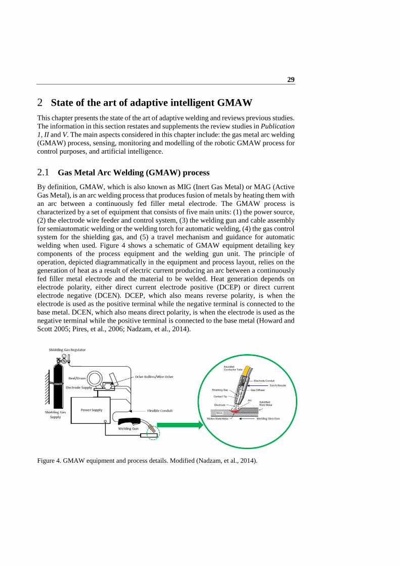
welding when used. Figure 4 shows a schematic of GMAW equipment detailing key
components of the process equipment and the welding gun unit. The principle of
operation, depicted diagrammatically in the equipment and process layout, relies on the
generation of heat as a result of electric current producing an arc between a continuously
fed filler metal electrode and the material to be welded. Heat generation depends on
electrode polarity, either direct current electrode positive (DCEP) or direct current
electrode negative (DCEN). DCEP, which also means reverse polarity, is when the
electrode is used as the positive terminal while the negative terminal is connected to the
base metal. DCEN, which also means direct polarity, is when the electrode is used as the
negative terminal while the positive terminal is connected to the base metal (Howard and
Scott 2005; Pires, et al., 2006; Nadzam, et al., 2014).
Figure 4. GMAW equipment and process details. Modified (Nadzam, et al., 2014).

State of the art of adaptive intelligent GMAW 30
Heat transfer and fluid flow is governed by arc plasma and forces in the form of
conduction and convection, including the flow of electrons. On reaching the base metal,
the heat of the arc melts the surface of the base metal and the end of the electrode, creating
a molten pool. The melted tip of the electrode is transferred across the arc to the molten
pool, resulting in a weld puddle/weld pool. Considering the magnitude of the wire voltage
and current, and size of the wire and the type of shielding gas, four modes of metal transfer
can be achieved: short-circuiting, spray, pulse-spray transfer and globular. Table 1 shows
key characteristics associated with the GMAW process.
Table 1. Key characteristics of GMAW process (Pires, 2006; Howard and Scott 2005;
Nadzam, et al., 2014).
GMAW process
Description
Arc types
In short-circuiting transfer, the metal is deposited during a short-circuiting (low voltage, short arc length and low current)
of the weld wire which normally lasts about 10 ms. Globular transfer occurs when voltage and current are increased above
the short arc welding and when the droplet diameter is larger than the electrode wire. Spray transfer occurs when the
weld droplets are smaller than the electrode wire. The transfer phenomenon is such that, the mean current increases and
the metal transfer goes from stubbing, short-circuits, globular and then to spray transfer mode. In pulse-spray transfer,
the mean current and the average heat input to the workpiece is lower than in spray transfer. Upon solidification, the
weld pool forms a fused joint, termed as the weld metal. An envelope of gas fed through the nozzle shields the arc, molten
pool, and the surrounding areas from contamination from the atmosphere. The type of metal transfer mode is a function
of the weld current controlled by both the static force balance theory and the pinch instability theory.
Shielding gases
Shielding gases help to stabilize the arc and influence the mode of metal transfers types, formation of weld bead contours
and elimination of weld spatter. The European standard EN ISO 14175 classifies welding consumables and gases, and
mixture of gases for fusion welding and allied processes. Therefore, shielding gases can be used in their pure state
(hydrogen: H2
, oxygen: O2
, carbon dioxide: CO2
, argon: Ar, nitrogen: N2
, Helium: He) or mixed together given a binary
blend (Ar + O2
, Ar + He, or Ar + CO2
), ternary blend (Ar + O2
+ He, Ar + CO2
+ O2
), or quaternary blend (Ar + O2
+ He +
CO2
, Ar + CO2
+ He + N2
). The most frequently used shielding gases are Ar, He and CO2
, and the other gases blended with
these for the purpose of modifying arc characteristics and the weld pool shape and size.
Effects of shielding gas
Pure argon produces a finger-like weld penetration and addition of helium increase thermal conductivity and provides
more puddle fluidity, and flatter bead shape. Argon enhances arc starting and promotes cleaning action when welding
aluminium. The addition of CO2
to Ar is suitable for carbon steel welding, as CO2
increase the heat generated. Oxygen is
an oxidizer that reacts with elements in the weld pool to form oxides. Blended with argon, oxygen enhances arc stability
and the appearance of the weld bead. The oxides float to the surface of the weld bead to form small islands. The float of
oxides is more prominent with CO2
shielding.
Filler materials
Selecting filler metal electrodes for GMAW process need several considerations. This include the electrode type, electrode
diameter, metal to be welded, thickness and joint design of the metal, surface conditions, specification or service condition
which should complement the shielding gas to be utilized. The mechanical and chemical properties of the electrode should
either match, overmatch or undermatch the properties of the base metal.
Initially, GMAW was developed for welding aluminium using spray mode of metal
transfer, argon gas for shielding, and a relatively large diameter electrode. The problem
encountered was the large uncontrollable molten weld pool. For steel welding, CO2

State of the art of adaptive intelligent GMAW 31
shielding gas and large diameter electrode wire (1.6 mm) were used. The metal transfer
was globular and spatter was greater than desired. Beside these problems, the manual
setting of welding parameters such as current, wire feed rate, welding speed and gas flow
rate were a challenge, thus producing weld joints with a lot of defects and imperfections
like weld porosity, irregular repartition, lack of weld penetration, weld embrittlement and
softening. These defects were a result of the limited control possibilities of the GMAW
process variations that were available at the time (Howard and Scott, 2005).
Recent developments of the GMAW process have seen the addition of microprocessors
and digital signal processors to control the process performance and arc stability, which
has led to vastly improving joint quality. A large number of proprietary process control
options exist (Norrish, 2017). These process control options, which are commonly known
as waveform-controlled welding processes, are defined according to ISO/TR 18491 as
“welding process modification of the voltage and current wave shape to control
characteristics such as droplet shape, penetration, wetting, bead shape or transfer
mode(s)” (ISO/TR 18491). Typical examples of GMAW waveform-controlled processes
include: pulse-spray transfer; controlled short circuit transfer; modified spray, combined
variants and AC operation; and synergic and self-regulation control, although other
variants of waveform-controlled processes exist (Mvola, 2017). Synergic and self-
regulating control can be seen as voltage control where the wire feed rate and voltage are
kept constant. A change in position causes the current to change, which prompts the filler
wire output to compensate for the change. GMAW processes can have tandem and multi
wire systems. These features produce a significant increase in welding speed and
deposition rate, and they influence the strength of the weld geometry.
Application of the GMAW process requires consideration of several parameters and
variables, which are inter-related and show nonlinear behaviour. Welding parameters
such as arc current, arc voltage, welding speed and gas flow rate are associated with heat
input. Welding parameters such as electrode stick-out, arc length, wire feed rate and wire
diameter are associated with contact tip to work distance (CTWD). In addition, welding
parameters such as torch position, torch travel angle and torch movement techniques are
associated with torch angle. If any of these nonlinear attributes of the GMAW process is
not appropriately set or controlled, defects associated with heat transfer and fluid flow
may occur. Investigation of heat transfer and fluid flow phenomena of the GMAW
process assists with understanding of the complexities of GMAW and provides a more
solid foundation for utilization of GMAW in adaptive welding of advanced steels.
2.1.1 Heat transfer and fluid flow
The GMAW process is complicated and involves nonlinear interaction of multiple
welding parameters and variables, and several numerical models have been developed to
describe and help understand heat transfer and fluid flow phenomena in GMAW and their
effects on weld configuration, welding position, and weld quality. Most of these three-
dimensional numerical models capture the dynamics of temperature profiles, weld pool
free surface profile, velocity fields, weld pool shape, thermal cycles, cooling rates and the

State of the art of adaptive intelligent GMAW 32
effects of the tilt angle. Recent developments in computer technology have led to the use
of CFD and finite element methods for computation of the welding process by analysing
the heat transfer and fluid flow to establish dynamic models between temperature fields
and weld pool surface deformation (Cho, et al., 2013;Wahab, 1998; Chen and Wu, 2009).
Modelling of GMAW for fillet joints performed by (Kumar, et al., 2005; Kumar and
DebRoy, 2007) provides improved understanding of the underlying scientific principles;
such understanding leads to good quality welds in practice. In the model, thermo-physical
properties such as thermal diffusivity and the specific heat needed for the computational
process are taken at 1745 K as a pre-set value. Additional heat transported by the weld
droplets into the weld pool is taken into account using a time-average volumetric heat
source term (Sv). The heat flux from the arc is assumed to have a Gaussian distribution
on the top surface of the weld pool. With these steady state conditions established, a
coordinate system is attached to the heat source in order to compute the heat transfer and
fluid flow during the GMAW process using continuity, momentum conservation and
energy conservation governing equations.
0i
i
u
x
(1)
( )i j j
j
i i i
u u uS
x x x
(2)
1 1
( ) ( )i i l lw w v
i i i i
u h u f fh hL U U L S
x x x x x x
(3)
Equation [1], [2], and [3] are the continuity, momentum conservation and energy
conservation equations respectively. The energy conservation equation comprises the arc
heat flux, heat dissipation by convection and radiation, and heat loss due to evaporation
(Cho, et al., 2013).The subscripts i and j denote the coordinate direction, x is distance, u
is the liquid metal velocity, ρ is the density, µ is the viscosity, Sj is the source term for the
jth momentum equation, h is the sensible heat, α is the thermal diffusion coefficient
(defined as α = k/Cp, where k is the thermal conductivity and Cp is the specific heat), Uw
is the material moving speed (parallel to the positive x direction, i.e., i=1 direction), L is
the latent heat of fusion, and Sv is a source term accounting for the additional heat from
the metal droplets. The source term Sj used in Equation [2] can be written as:
2
3
1
(1 )j e b ilj w j j j j
j l
u fpS U C u F F F
x x f B
(4)
Where p represents pressure; fl is the liquid metal fraction; and Fej, F
bj and Fi
j correspond
to the electromagnetic, buoyancy and inertia forces in the jth direction respectively. The
third term in Equation [4] represents the frictional dissipation in the mushy zone (a semi-

State of the art of adaptive intelligent GMAW 33
solid region of the weld) according to the Carman-Kozeny approximation, where B and
C are two constants. The liquid metal fraction, fl, is assumed to vary linearly with
temperature inside the mushy zone:
S
S
1
T - Tf
T - T
0
S
s
T T
T T < T
T T
(5)
Where Tl and Ts are the liquidus and solidus temperature of the material respectively.
Figure 5 presents an illustration of plots of heat transfer and fluid flow under investigation
in GMAW process analysis.
Figure 5. Illustration plots of: a) coordinate transformation from the physical domain; b)
nomenclature of GMAW fillet weld geometry (Kumar, et al., 2005); and temperature profiles and
fluid flow pattern on a transverse cross-section: c) 1.52 s; d) 2.0 s (Cho, et al., 2013).
(a)
(b)
(c) (d)

State of the art of adaptive intelligent GMAW 34
In Figure 5(a), a coordinate transformation from the physical domain is shown. Figure
5(b) provides a nomenclature of GMAW fillet weld geometry (Kumar, et al., 2005).
Figures 5(c) and 5(d) present a simulated case of calculated temperature profiles and flow
patterns on a transverse cross-section when time was varied from 1.52 s and 2.0 s
respectively (Cho, et al., 2013). It can be clearly seen from Figure 5(c) and 5(d) that the
heat transfer and fluid flow pattern changes with respect to time. Heat transfer assumes a
circulation path from the top of the weld pool to the bottom, whereas the metal fluid flows
in a laminar pattern. After some few seconds, and depending on the temperature of the
fluid, the heat transfer assumes a linear direction from the bottom of the molten weld pool
to the top.
2.1.2 Relative effects on weld quality of fillet joints
Non-dimensional properties and driving forces are present in the GMAW process. The
relationship between these variables have effects on weld quality, temperature
distribution, velocity field, weld bead surface profile, etc. It has been established that
during fillet welding, the weld pool top surface under the electrode is depressed by the
arc force, which consequently deforms the weld pool surface profile. The energy from
the arc is transported from the top surface of the weld pool to the surrounding solid region
by both heat conduction and liquid metal convection (Kumar, et al., 2005; Kumar and
DebRoy, 2007). Likewise, in the weld pool, heat is transported by convection and
conduction (Cho, et al., 2013). The rate of heat transfer in the workpiece determines the
shape of the weld pool, peak temperature, and temperature distribution in the HAZ.
The case of GMAW of structural steel A-36 provides a situational example for
understanding the various non-dimensional properties and driving forces (Kumar, et al.,
2005; Kumar and DebRoy, 2007). Table 2 shows the physical properties of the A-36 steel
and other data used in the computational analysis. The values of the non-dimensional
properties are shown in Table 3 for a given set of welding parameters: 312.0 A (arc
current), 31.0 V (voltage), 4.2 mm/s (welding speed) and 169.3 mm/s (wire feed rate).
The equations of the non-dimensional properties including that of the driving forces are
shown in Table 4.
Table 2. Physical properties of A-36 and data for computational analysis.
Name Value
Liquidus temperature, Tl (K) 1785
Solidus temperature, Ts (K) 1745
Density of steel, ρ (kg m-3
) 7.8 x 10³
Thermal conductivity of solid, ks (J m-1
s-1
K-1
) 21.0
Specific heat of solid, Cps (J kg-1
K-1
) 703.4
Specific heat of liquid, Cpl (J kg-1
K-1
) 808.1
Surface tension of liquid metal at melting point, ˠ (N m-1
) 1.2
Temperature coefficient of surface tension, dˠ/dT (N m-1
K-1
) -3.5 x 10 -4
Magnetic permeability, µm (N A-2
) 1.26 x 10 -6

State of the art of adaptive intelligent GMAW 35
Coefficient of thermal expansion, β (K-1
) 1.0 x 10 -5
Arc efficiency, ɳ 54%
Arc radius, rb (mm) 5.0
Convective heat-transfer coefficient, hc (W mm-2
K-1
) 42.0
Emissivity, ε 0.7
Ambient temperature, Ta (K) 298
Constant B in the Carman-Kozeny equation 1.0 x 10 -7
Constant C in the Carman-Kozeny equation 1.6 x 10⁴
Table 3. Non-dimensional properties of the GMAW process.
Non-dimensional properties Value
Peclet number (PE) 120
Grashof Number (Gr) 11.9
Froude Number (Fr) 0.27
Magnetic Reynold’s number (Rm) 3.3 x 10
4
Surface tension Reynold’s number (Ma) 2.9 x 10
4
The fluid flow (liquid-metal motion) mechanism in GMAW is quite complex due to the
combined effects of the various driving forces: electromagnetic, Marangoni and
buoyancy forces. In addition, the forces of inertia, surface tension, gravity and viscosity
play major role. In determining the relative significance of convection verses conduction
in transfer of heat in the weld pool, the Peclet number (Pe) is used.
Table 4. Driving forces and non-dimensional properties in the GMAW process (Kumar,
et al., 2005; Kumar and DebRoy, 2007).
Driving
forces
and
Heat flux
Electromagnetic
force F J x Be (6) Where J and B are the current flux and magnetic field in the workpiece respectively.
Buoyancy force
F cos cos ( )4
b
refg T T
(7)
Using the Boussinesq approximation, the gravity (buoyancy) force is given: where g is the
acceleration due to gravity and is in the negative Z direction; θ is the tilt angle or inclination
of plates from the horizontal position, φ is the angle of lift from the horizontal plane, β is
the thermal expansion coefficient; and T and Tref
are the local and arbitrarily selected
reference temperatures.
Inertia force
F sin i + g cos j4
i g
(8)
Where i and j are the unit vectors in the x and y directions respectively. Heat flux
( )b b c ah n F h T T (9)

State of the art of adaptive intelligent GMAW 36
For the bottom surface, the heat flux is given: where nb
is a unit normal vector to the bottom
surface, hc is the convective heat-transfer coefficient, and T
a is the ambient temperature (a
value of 298 K is used). The temperature at the other surfaces, i.e., east, west, south, and
north surfaces, are set to the ambient temperature. Non-
dimensional
properties
Peclet number
Pe = R pl Rconvection
conduction l
u C Lheat
heat k
(10)
Where uR
and LR
are the characteristic velocity and length in the weld pool respectively; p
is the density; and Cpl
and Kl are the specific heat and thermal conductivity of liquid metal
respectively.
Grashof number 3 2
2Gr Bg L T
u
(11)
Where g is the acceleration due to gravity, β is the thermal expansion coefficient, ∆T is the
temperature difference between the peak pool temperature and solidus temperature, ρ is the
density of the liquid-metal, µ is the viscosity of the liquid-metal, and LB
is a characteristic
length for the buoyancy force in the liquid pool and is approximated by one-eighth of the
pool radius.
Froude number
1/2
inertia forceFr
gravity force
u
gH
(12)
Where u is the average liquid velocity in the weld pool and H is the characteristic depth of
the liquid pool and is approximated by the value of weld bead throat dimension. Reynold’s
number
2
2 2Rm =
4
mI
(13)
Where µm
and µ are magnetic permeability and viscosity of the liquid metal respectively. Surface tension
Reynolds
number 2
Ma =R
dL T
dT
(14)
Where LR
is the characteristic length and dˠ/dT is the surface temperature gradient. Ratio of surface
tension force to
buoyancy force
/S B
MaR
Gr (15)
Ratio of
electromagnetic
force to buoyancy
force
/M B
RmR
Gr (16)
When the Pe number is higher than unity, heat transfer in the weld pool is caused by
convection due to high liquid metal velocity and larger weld pool size. Contrarily, when
the Pe number is less than unity, heat transfer by conduction is the cause of heat
dissipation in the weld pool. Since the Pe number in the case of A-36 steel is higher than
unity, the liquid metal convection mechanism is the dominant factor in dissipation of the
heat in the weld pool. The ratio of the buoyancy force to the viscous force is determined

State of the art of adaptive intelligent GMAW 37
by the Grashof number. The Grashof number is much higher than unity, as seen from
Table 3, causing the viscous force to be negligible compared to the buoyancy force. The
property value of the Froude number (Fr) is much higher than unity, causing the inertia
force to dominate the flow in the weld pool. If Fr is much less than unity, the buoyancy
or gravity force dominates the liquid metal flow (Kumar et al., 2005; Kumar and DebRoy,
2007).
The magnetic Reynold’s number, Rm, expresses the ratio of the electromagnetic force to
the viscous force. The Rm value is significantly higher than unity, which suggests that
the electromagnetic force is very dominant compared to the viscous force. The surface
tension Reynold’s number (Ma) is used to describe the ratio of the Marangoni force to
viscous force. The value of Ma is of the same order of magnitude as Rm. However, the
value of Gr is very low compared to Rm and Ma, which means that the effect of the
buoyancy force is very low compared to the electromagnetic and Marangoni forces.
In describing the relative importance of the driving forces, the following dimensionless
properties can be formulated. The ratio of the surface tension force to the buoyancy force
is defined as RS/B, and the ratio of the electromagnetic force to the buoyancy force is given
as RM/B. However, for GMAW of fillet joints, the values of RS/B and RM/B are found to be
2.4 x 10³ and 2.8 x 10³ respectively. These values suggest that the liquid metal flow in
the molten pool is driven chiefly by the Marangoni and electromagnetic forces, and to a
much lesser extent by the force of buoyancy. Furthermore, the electromagnetic force
plays a major role during GMAW of fillet joints (Kumar et al., 2005; Kumar and DebRoy,
2007). Figure 6 shows an illustration of the various forces and the flow pattern of the weld
pool in GMAW.
Figure 6. Illustration of the various forces and the flow pattern of the weld pool in GMAW.
In symmetrically V-shape fillet welding, the effect of high arc pressure causes a deep
finger penetration, although some research suggests that weld droplet impingement is the
dominant reason for fingertip penetration (Mendez and Eagar, 2003; Essers and Walter,
1981).The liquid metal flows downward in the middle of the weld pool driven by the
electromagnetic force, assisted by gravity and the plasma drag force (Cheon, et al., 2016).
A major counterclockwise circulation loop is formed along the central longitudinal plane.

State of the art of adaptive intelligent GMAW 38
However, at the top surface of the weld pool, the Marangoni shear stress drives the melt
from the center to the edge of the weld pool in the region close to the heat source, where
the variation of the surface temperature is relatively high (Kumar et al., 2005).
Due to the difference in flow patterns resulting from the electromagnetic and Marangoni
forces, the leg length of the weld pool decreases, while the actual throat is increased due
to weld penetration, as shown in Figure 5 (b). However, the situation illustrated in Figure
5 (b) is not a general case, especially when different workpiece orientations and welding
positions are used. It is claimed that when weld droplet flight distance increases, weld
penetration becomes deeper (Cheon, et al., 2016), which may have a resultant effect on
the length of the weld leg and weld pool size. Consequently, it is further asserted that an
increase in CTWD causes low arc heat intensity at the surface of the weldment, thus
reducing the inert gas density effect on weld penetration as a result of dissipation of the
arc heat intensity (Nestor, 1962).
Workpiece orientation and welding position affect the strength and integrity of the welded
joint due to changes in the weld bead geometry (Bowditch, 1997). For L-shape fillet
welding, the buoyancy and inertia forces affect the temperature distribution and the
velocity fields in the workpiece. The depth of weld penetration is not as deep as in the
V-shape. With an increase in the tilt angle of the workpiece, weld penetration increases
and the width of the weld pool decreases, as shown in Figure 7.
Figure 7. Temperature and velocity fields at different cross-sectional planes in (a) V-shaped joint
and (b) L-shaped joint. Modified (Kumar and DebRoy, 2007).
The dynamic behavior and effects of fillet joint orientation on the free surface profile,
temperature distribution, velocity field, weld pool shape and size due to the driving forces

State of the art of adaptive intelligent GMAW 39
and dimensionless properties present some level of justification for automation of the
GMAW process in adaptive welding setting. Automation enables the complexities in
GMAW welding to be addressed in a more consistent manner, resulting in more
dependent weld quality, improved productivity and superior weld quality assurance.
2.1.3 Automating the manual operation of the GMAW process
The versatility, flexibility, productivity and adaptability of the GMAW process make it
one of the most commonly used fusion welding processes in the welding industry. The
GMAW process can be used to weld almost all metallic materials having thickness above
30 mm, it is effective in all welding position, has higher speeds and gives higher
deposition rates than manual metal arc welding (stick welding). However, the process is
not without its complications. The need to automate its operational functionalities to
mimic an experienced welder stem primarily from issues related to positioning the
welding torch, controlling the welding parameters, and holding and manoeuvring the
welding torch in a precise and controlled manner. Automation is also required to produce
more consistent weld quality, reduce production cost, and increase production volume
even when operating in non-human friendly environments. Databases and programmable
software, IO control and data acquisition systems, communication interfaces and
protocols incorporated into robots are available for the purpose of automating the GMAW
process.
Automated GMAW processes, referred to herein as robotic GMAW, rely on the
kinematics of the robot manipulator and dexterity of the robot end effector for effective
operation and performance. Table 5 shows a summary of the characteristics of robot
manipulators. The robot manipulator characteristics make it possible to define
positions/orientations, define reference systems, parameterize trajectories and other
actions, and run the program continuously with high precision and repeatability (Chen
and Wu, 2009).
Table 5. Robot manipulators main characteristics (Chen and Wu, 2009).
Nevertheless, robotic GMAW has drawbacks in relation to real-time monitoring and
sensing and control capabilities. Pre-setting of the geometrical parameters of the weld,
Repeatability Up to 0.03 mm (0.1 mm is common)
Velocity Up to 5 m/s
Acceleration Up to 25 m/s2
Payload From around 2-3 kg up to ~ 750 kg
Weight/Payload Around 30-40
Axis 6 degree of freedom
Communications Profibus, Canbus, devicenet, ethernet and serial channels (RS232 and
RS485)
IO Capabilities PLC like capabilities to handle digital and analog IO

State of the art of adaptive intelligent GMAW 40
real-time monitoring of the welding operation, re-adjustment of the welding parameters
and variables, and overall control of the entire welding operation present significant
challenges in the application of robotic GMAW processes. The movement of the welding
gun in corners, irregular wire feeding, unstable arc and weld discontinuities (porosity,
lack of penetration, excessive melt-through, cracks) present further challenges (Ushio and
Mao, 1994; Nomura, 1994). There is always the need to check, adjust or pre-program
welding parameters before or after the welding operation. These routines, which are
somewhat cumbersome, could be alleviated by adaptive welding systems based on data
from sensing and monitoring systems.
2.2 Sensing and monitoring of the robotic GMAW process
Sensing and monitoring capabilities have advanced considerably in recent years.
Integration of sensing and monitoring devices would enhance GMAW performance
through motion control, monitoring of the entire welding process in real-time, joint
detection and recognition, seam tracking (capture seam data and store weld data) while
coordinating with other devices to respond appropriately in adjustment of output settings
(Chen and Wu, 2009; Huanca and Adsi, 2010).
Sensors utilized for welding purposes measure parameters related to the welding process
as they play a significant role as the major source of input to the control system that
manage and control the behaviour and output of the welding system. The stored
parameters are used to control the welding process in accordance with defined WPS
(example shown in Appendix Table 4). In robotic GMAW, measured sensor information
can be used for controlling both the welding power source and the robot manipulator.
However, using only one sensor to perform these functions and additionally observe other
parameters like joint geometry is not feasible. For these reasons, a robotic GMAW system
needs multiple sensors and monitoring devices for optimum performance. Sensors for
welding robots are divided into two groups, technological and geometrical sensors.
Technological sensors measure parameters related to the welding process and geometrical
sensors measure parameters related to weld joint geometry (Chen and Wu, 2009).
2.2.1 Sensing technological parameters
Sensors for technological parameters must be able to obtain information on arc voltage,
current and wire feed rate. Measurement of the arc voltage can be done in several different
ways. A reliable way is to measure the arc voltage on the wire inside the wire feeding
system, which avoids errors from voltage drop (Rosheim, 1994; Pires, et al., 2006). The
wire at this position does not carry any current so the voltage of the wire at the contact
tube will be the same. For welding current measurements, two basic types of sensors are
used: Hall effect and current shunt sensors. The principle of the Hall sensor involves a
circular core of cast iron through which the cable that carries the current flows. The sensor
device, consisting of a doped silicon plate, is placed in the gap in the iron core with two
pairs of connecting cables. The first pair feeds the device with current and the device

State of the art of adaptive intelligent GMAW 41
responds by delivering a signal to the second pair of cables that is proportional to the
magnetic field and the current. The benefit of the Hall sensor is that it is contactless and
does not interfere with the current of the welding power source (Mvola, 2017). The
current shunt sensor operates by letting current flow through a resistor and the voltage
across the resistor is measured. Figure 8 shows the three sensor types for measuring
technological parameters.
Figure 8. Technological sensing approaches: a) arc voltage, (b) Hall effect, (c) current shunt.
Modified (Mvola, 2017).
2.2.2 Sensing geometrical parameters
Sensors used to obtain welding information about geometrical parameters primarily
measure the geometry of the weld joint, deviation from a nominal path, position and
orientation changes in joints, and workpiece and gap size. In some cases, location
techniques can be applied for locating workpieces by using image recognition to detect
the position of some plates of the workpiece. Such information is of great significance
when performing seam tracking for use in quality control of the welding process.
However, geometrical sensors face challenges arising from the harsh arc environment
with high temperatures, fumes from the shielding gases, spatter from hot molten metal,
electromagnetic fields and other driving forces, arc disturbance and noise, high current
and intensive light radiations. These challenges affect the performance of the sensors, and
purpose-built sensors must be utilized. The most common and frequently used sensors in
this category are optical sensors and through-arc-sensors (Chen and Wu, 2009).
Most optical sensors, known as active direct visual sensors, use laser or light structures
and an in-built camera. Laser beams are characterised by high intensity, directionality,
monochromaticity and coherence (Chen and Wu, 2009). The laser light is applied on the
weld joint under study and a camera with a narrow bandwidth filters the laser beam to
extract the geometrical weld data of interest. In detection and recognition of weld data,
the projected laser beam is moved in a scanning motion across the seam and a
semiconductor charge-coupled device (CCD) camera or complimentary metal-oxide
semiconductor (CMOS) is used to measure features of the weld joint from the laser strip.
The laser strip in this case may not be a linear line on the joint but rather circular to detect
weld joints also in corners from one location of the torch or point of view of the sensor.
(a) (b) (c)

State of the art of adaptive intelligent GMAW 42
The CCD camera measures the distance on the joint using the method of laser
triangulation (Pires, et al., 2006; Chen and Wu, 2009).
The other common form of optical sensors, known as passive direct visual sensors, use
the light of the arc without an additional secondary light source. Optical sensors are often
mounted on the welding torch as a technique to have the weld joint in its field of view
some distance ahead in the weld travel direction. Based on laser triangulation, optical
seam trackers are capable of keeping the robot “on track” with the weld joint during
welding in real-time. Added capabilities of optical sensors include recognition of joint
volume, misalignment and tack welds based on a feature extraction algorithm. These
capabilities of optical sensors can provide information for adaptive feed-back control of
both the welding power source and the robot and can perform the defined tasks according
to weld quality standards of the WPS (Pires, et al., 2006). Figure 9 shows the two
geometric sensing approaches.
Figure 9. Geometric sensing approaches: (a) Laser vision principle (Pires, et al., 2006), (b)
definition of tool centre point and weaving direction during through-arc sensing (Fridenfalk,
2003).
Through-arc sensors, also known as seam tracking, use the weaving motion technique
and the arc itself as the sensor. The technique relies on the change in current when the
distance between the contact tube and the workpiece varies. The approach is commonly
used for seam tracking methods in robotic GMAW due to it being cost-effective compared
to optical sensors. Mathematically, the approximate relationship between arc voltage (U),
arc current (I) and the CTWD (l) is expressed as:
U = β1I + β2 + β3 / I + β4l (17)
where β1 - β4 are constants dependant on factors like wire diameter, gas flow and the
characteristics of the welding power source. The welding power source is set to maintain
(a) (b)
State of the art of adaptive intelligent GMAW 43
a constant voltage. When the l varies, the arc current I will also vary; therefore, a longer
CTWD will result in a lower arc current given that all other parameters are kept constant.
As the current is measured using the Hall effect or current shunt, a low-pass filter is
employed to depress noise from the signal. Weld information from the through-arc sensor
can be retrieved either through continuous measurement of the current or by measurement
at the turning points of the weaving motion (Cook, et al., 1987).
Other arc welding sensing methods also exist: ultrasonic methods for sensing weld
penetration (Hardt, 1984), arc pressure sensors to sense vibration information of the weld
pool (Li, 1997), infrared thermography to sense the welding temperature field (Nagarajan
1989; Menaka, et al., 2005; Venkatraman, 2006; Gyasi, et al., 2017; Gyasi, et al., 2018),
X-ray method to sense the shape of the welding pool, acoustic sensors, high speed CCD
cameras and stroboscopic vision cameras (Chen and Wu, 2009). Sensors that do not have
monitoring capabilities (feature recognition) should be complemented with monitoring
systems when employed for a robotic GMAW process. Monitoring systems that record
and capture welding data provide better observation and prediction of the behaviour of
the welding process, as well as enhance total control of the welding.
2.2.3 Monitoring of process variables and parameters
Monitoring systems for arc welding have in-built feature recognition and extraction
capabilities, which should be able to classify different weld parameters and or features
that indicate the quality of the weld with respect to pre-set values and provide these as a
basis for further control actions during the welding process. Commercially available
monitoring systems for weld parameters include ADM III, Arc Guard, Analysator
Hannover 10.1, and Weldcheck. These systems all work in a similar manner by measuring
voltage, current and other process signals and comparing the measured values with pre-
set nominal values. An alarm is triggered when there is a difference to the pre-set values
that exceeds a given threshold. For WPS conformance, the alarm threshold is defined with
respect to the WPS to maintain the welding process within nominal parameter limits and
at the same time produce welds at the defined quality and productivity levels of the WPS
(Pires, et al., 2006).
As mentioned earlier, some arc welding sensors have monitoring capabilities, which helps
to reduce production cost and assure and improve weld quality and integrity. To be able
to provide explicit information on weld quality, reference data (existing knowledge or
information) must be available, including models or algorithms that describe and evaluate
measured parameters (Pires, et al., 2006). A monitoring system with arc welding
sensoring is necessary for control purposes of the entire welding process. Therefore,
monitoring of a robotic GMAW process requires information about the mode of metal
transfer, and using welding parameters, heat transfer and material flow equations must be
formulated in development of algorithms for control purposes. For example, in a pulse-
spray GMAW process, the criterion for detachment of one droplet per pulse is governed
by the relationship:
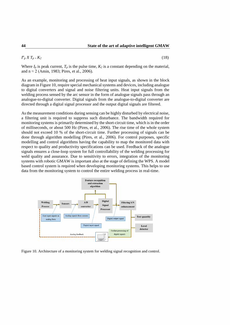
State of the art of adaptive intelligent GMAW 44
Inp X Tp = K2 (18)
Where Ip is peak current, Tp is the pulse time, K2 is a constant depending on the material,
and n ≈ 2 (Amin, 1983; Pires, et al., 2006).
As an example, monitoring and processing of heat input signals, as shown in the block
diagram in Figure 10, require special mechanical systems and devices, including analogue
to digital converters and signal and noise filtering units. Heat input signals from the
welding process sensed by the arc sensor in the form of analogue signals pass through an
analogue-to-digital converter. Digital signals from the analogue-to-digital converter are
directed through a digital signal processor and the output digital signals are filtered.
As the measurement conditions during sensing can be highly disturbed by electrical noise,
a filtering unit is required to suppress such disturbance. The bandwidth required for
monitoring systems is primarily determined by the short-circuit time, which is in the order
of milliseconds, or about 500 Hz (Pires, et al., 2006). The rise time of the whole system
should not exceed 10 % of the short-circuit time. Further processing of signals can be
done through algorithm modelling (Pires, et al., 2006). For control purposes, specific
modelling and control algorithms having the capability to map the monitored data with
respect to quality and productivity specifications can be used. Feedback of the analogue
signals ensures a close-loop system for full controllability of the welding processing for
weld quality and assurance. Due to sensitivity to errors, integration of the monitoring
systems with robotic GMAW is important also at the stage of defining the WPS. A model
based control system is required when developing monitoring systems. This helps to use
data from the monitoring system to control the entire welding process in real-time.
Figure 10. Architecture of a monitoring system for welding signal recognition and control.

State of the art of adaptive intelligent GMAW 45
2.3 Modelling the robotic GMAW process for control purposes
Modelling of the robotic GMAW process has to be done in two ways: a) using a
theoretical approach, which involves solving the physical problems analytically; and b)
using a technological approach, which takes understanding of the welding process from
the theoretical perspective as a basis for performing empirical studies based on detailed
experimentation to ascertain the governing models.
Due to the nonlinear nature of the GMAW process, many parameters need to be addressed
theoretically and technologically before, during and after the welding process. Before
welding, parameters denominated as fixed inputs need to be defined. The fixed inputs
include the prepared joint geometry, plate thickness and physical properties of the
material. Also welding parameters and variables such as shielding gas, gas flow rate, torch
angle, and type and size of the wire need to be determined before welding. These
secondary inputs rely on the primary inputs and any changes in these parameters will
affect the welding process. In addition, any changes in the primary inputs (arc voltage,
current, wire feed rate, torch travel speed) will affect the welding process greatly. Another
essential set of parameters are the output parameters. Such parameters are metallurgically
and geometrically defined and they are obtained after welding since they characterize the
weld and are used to evaluate its quality.
2.3.1 Geometrical and theoretical modelling approaches
Geometrical parameters are classified according to weld penetration, weld bead width,
weld bead height, length of the leg of the weld metal, weld metal throat thickness, weld
toe contours, weld root penetration, etc. The welding standard EN ISO 5817 defines
geometrical parameters for fillet and butt welded joints. Metallurgical characteristics
which rely primarily on heat input for good metal fusion, penetration, temperature
distribution and cooling rates, which affect weld solidification, play a major role in weld
quality. They dictate and determine specific mechanical characteristics like hardness,
tensile strength, residual stresses, and the integrity and reliability of the weld joint. These
specific characteristics of the weld joint cannot be measured on-line, only after the
welding process. Adaptive control could help achieve flawless welds by ensuring the
desired mechanical and metallurgical properties of the weld and controlling the formation
of the appropriate microstructure during solidification. Accurate definition of these
requirements are dependent on an accurate model of the robotic GMAW process.
Sub-chapters 2.1.1 and 2.1.2 of this work introduced a theoretical (analytical) approach
used in modelling of the GMAW process. The analytical study provides a foundation to
further develop modelling for the GMAW process to enhance repeatability and
consistency. This model development requires the findings of geometrical (empirical)
study to refine the model to the accuracy desired. With robotic GMAW, a robust
modelling system is very much needed due to the complexity and nonlinearity of the
system integration between the robot and the GMAW process. Adopting the geometrical
approach requires the following: a) a knowledge base, and b) sensors and interfaces.
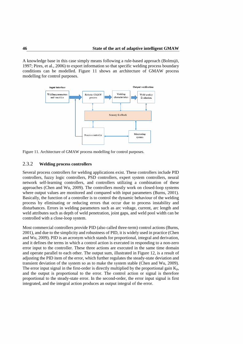
State of the art of adaptive intelligent GMAW 46
A knowledge base in this case simply means following a rule-based approach (Bolmsjö,
1997; Pires, et al., 2006) to export information so that specific welding process boundary
conditions can be modelled. Figure 11 shows an architecture of GMAW process
modelling for control purposes.
Figure 11. Architecture of GMAW process modelling for control purposes.
2.3.2 Welding process controllers
Several process controllers for welding applications exist. These controllers include PID
controllers, fuzzy logic controllers, PSD controllers, expert system controllers, neural
network self-learning controllers, and controllers utilizing a combination of these
approaches (Chen and Wu, 2009). The controllers mostly work on closed-loop systems
where output values are monitored and compared with input parameters (Burns, 2001).
Basically, the function of a controller is to control the dynamic behaviour of the welding
process by eliminating or reducing errors that occur due to process instability and
disturbances. Errors in welding parameters such as arc voltage, current, arc length and
weld attributes such as depth of weld penetration, joint gaps, and weld pool width can be
controlled with a close-loop system.
Most commercial controllers provide PID (also called three-term) control actions (Burns,
2001), and due to the simplicity and robustness of PID, it is widely used in practice (Chen
and Wu, 2009). PID is an acronym which stands for proportional, integral and derivation,
and it defines the terms in which a control action is executed in responding to a non-zero
error input to the controller. These three actions are executed in the same time domain
and operate parallel to each other. The output sum, illustrated in Figure 12, is a result of
adjusting the PID item of the error, which further regulates the steady-state deviation and
transient deviation of the system so as to make the system stable (Chen and Wu, 2009).
The error input signal in the first-order is directly multiplied by the proportional gain Kp,
and the output is proportional to the error. The control action or signal is therefore
proportional to the steady-state error. In the second-order, the error input signal is first
integrated, and the integral action produces an output integral of the error.

State of the art of adaptive intelligent GMAW 47
This means that the error is integrated and multiplied by KI. However, in some instances,
the steady-state errors may be eliminated. The third-order, which is the derivative action,
occurs when the error is first differentiated and multiplied with KD (Owen, 2012). The
control logic of the PID controller is implemented by finding suitable gain parameters of
KP, KI, and KD.
Figure 12. PID controller layout. Modified (Owen, 2012).
Despite its fast regulating speeds, simplicity and common use, the PID controller has
problems when controlling nonlinear systems and systems having parameter variations.
Their deficient performance leads to overshooting and instability in the system. GMAW
operations, where a lot of parameters and variations have to be controlled, could pose
challenges to PID controllers. Much research work in welding has combined PID with
other artificial intelligent systems like fuzzy logic, ANN, etc. to eliminate the drawbacks
of PID controllers and enable optimal control of the welding process (Chen and Wu,
2009). As most robots use PID controllers, there is a need to synchronize the PID control
mechanism with an intelligent modelling system having control capabilities. Modelling a
control system using artificial intelligence is presented in the next section. A framework
of an intelligent PID controller system for robotic GMAW process is also described.
2.4 Artificial intelligence modelling and control of robotic GMAW
Artificial intelligence (AI) is a broad field that draws upon mathematics, computer science
and other related subjects to develop approaches that enable machines to mimic the
cognitive functions of humans. These functions include learning, reasoning, decision-
making, retaining knowledge and problem solving. For some machines like robots, the
ability to move and manipulate objects in a precise and repetitive manner is a desired
function. In the GMAW domain, robotic systems that incorporate AI could perform
functions similar to those carried out by human welders.
Some of the key approaches or systems of AI that are incorporated into robots include
artificial neural networks (ANN), fuzzy logic, neural-fuzzy networks and adaptive neuro-
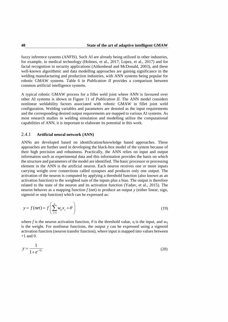
State of the art of adaptive intelligent GMAW 48
fuzzy inference systems (ANFIS). Such AI are already being utilized in other industries,
for example, in medical technology (Holmes, et al., 2017; Lopez, et al., 2017) and for
facial recognition in security applications (Aitkenhead and McDonald, 2003), and these
well-known algorithmic and data modelling approaches are gaining significance in the
welding manufacturing and production industries, with ANN systems being popular for
robotic GMAW systems. Table 6 in Publication II provides a comparison between
common artificial intelligence systems.
A typical robotic GMAW process for a fillet weld joint where ANN is favoured over
other AI systems is shown in Figure 11 of Publication II. The ANN model considers
nonlinear weldability factors associated with robotic GMAW in fillet joint weld
configuration. Welding variables and parameters are denoted as the input requirements
and the corresponding desired output requirements are mapped to various AI systems. As
most research studies in welding simulation and modelling utilize the computational
capabilities of ANN, it is important to elaborate its potential in this work.
2.4.1 Artificial neural network (ANN)
ANNs are developed based on identification/knowledge based approaches. These
approaches are further used in developing the black-box model of the system because of
their high precision and robustness. Practically, the ANN relies on input and output
information such as experimental data and this information provides the basis on which
the structure and parameters of the model are identified. The basic processor or processing
element in the ANN is the artificial neuron. Each neuron receives one or more inputs
carrying weight over connections called synapses and produces only one output. The
activation of the neuron is computed by applying a threshold function (also known as an
activation function) to the weighted sum of the inputs plus a bias. The output is therefore
related to the state of the neuron and its activation function (Yadav, et al., 2015). The
neuron behaves as a mapping function f (net) to produce an output y (either linear, sign,
sigmoid or step function) which can be expressed as:
1
( )n
ij j
j
y f net f w x
(19)
where f is the neuron activation function, θ is the threshold value, xj is the input, and wij
is the weight. For nonlinear functions, the output y can be expressed using a sigmoid
activation function (neuron transfer function), where input is mapped into values between
+1 and 0.
1
1 Txy
e
(20)
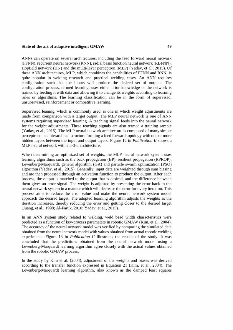
State of the art of adaptive intelligent GMAW 49
ANNs can operate on several architectures, including the feed forward neural network
(FFNN), recurrent neural network (RNN), radial basis function neural network (RBFNN),
Hopfield network (HN) and the multi-layer perceptron (MLP) (Yadav, et al., 2015). Of
these ANN architectures, MLP, which combines the capabilities of FFNN and RNN, is
quite popular in welding research and practical welding cases. An ANN requires
configuration such that the inputs will produce the desired set of outputs. The
configuration process, termed learning, uses either prior knowledge or the network is
trained by feeding it with data and allowing it to change its weights according to learning
rules or algorithms. The learning classification can be in the form of supervised,
unsupervised, reinforcement or competitive learning.
Supervised leaning, which is commonly used, is one in which weight adjustments are
made from comparison with a target output. The MLP neural network is one of ANN
systems requiring supervised learning. A teaching signal feeds into the neural network
for the weight adjustments. These teaching signals are also termed a training sample
(Yadav, et al., 2015). The MLP neural network architecture is composed of many simple
perceptrons in a hierarchical structure forming a feed forward topology with one or more
hidden layers between the input and output layers. Figure 12 in Publication II shows a
MLP neural network with a 3-3-3 architecture.
When determining an optimized set of weights, the MLP neural network system uses
learning algorithms such as the back propagation (BP), resilient propagation (RPROP),
Levenberg-Marquardt, genetic algorithm (GA) and particle swarm optimization (PSO)
algorithm (Yadav, et al., 2015). Generally, input data are weighted through sum biasing
and are then processed through an activation function to produce the output. After each
process, the output is matched to the output that is desired, and the difference between
them gives an error signal. The weight is adjusted by presenting the error back to the
neural network system in a manner which will decrease the error for every iteration. This
process aims to reduce the error value and make the neural network system model
approach the desired target. The adopted learning algorithm adjusts the weights as the
iteration increases, thereby reducing the error and getting closer to the desired target
(Juang, et al., 1998; Al-Faruk, 2010; Yadav, et al., 2015).
In an ANN system study related to welding, weld bead width characteristics were
predicted as a function of key-process parameters in robotic GMAW (Kim, et al., 2004).
The accuracy of the neural network model was verified by comparing the simulated data
obtained from the neural network model with values obtained from actual robotic welding
experiments. Figure 13 in Publication II illustrates the results of the study. It was
concluded that the predictions obtained from the neural network model using a
Levenberg-Marquardt learning algorithm agree closely with the actual values obtained
from the robotic GMAW process.
In the study by Kim et al. (2004), adjustment of the weights and biases was derived
according to the transfer function expressed in Equation 21 (Kim, et al., 2004). The
Levenberg-Marquardt learning algorithm, also known as the damped least squares

State of the art of adaptive intelligent GMAW 50
method, provides numerical solutions by reducing error when solving complicated
boundary value problems.
∆W = (JTJ + μI)−1JTe (21)
where J is Jacobian matrix of derivation of each error, µ is a scalar, and e is error function.
In other expressions, the Levenberg-Marquardt algorithm can be derived by considering
the error E, after a differential change in the neural network weights from u0 to u according
to the second order Taylor series expansion, as shown in Equation 22. Additionally, the
Jacobian matrix is used to define the Hessian for the special case of sum of squared error,
as expressed in Equation 23 (Yadav, et al., 2015).
E(u) = E(u0) + f T(u − u0) + 1
2(u − u0)TH(u − u0) + ⋯ (22)
H = 2 JTJ + 2∂JT
∂uF (23)
The Levenberg–Marquardt algorithm improves the overall accuracy of neural network
systems since it can provide a faster convergence than other learning algorithms such as
the backpropagation algorithm (Yadav, et al., 2015). Therefore, in welding, where
accurate setting of welding variables and parameters is imperative, adopting the
Levenberg–Marquardt learning algorithm in artificial neural network systems could
guarantee accurate predictions.
2.4.2 Intelligent control using ANN
Several control systems have combined the intelligence of a fuzzy logic controller with
ANN, PID controller with ANN, fuzzy logic and PID with ANN, or ANN self-learning
controller for controlling welding processes in real-time (Chen and Wu, 2009). Hirai
(Hirai, 2001) used a fuzzy-ANN controller in robotic MIG welding for penetration control
and weld penetration depth prediction. Andersen and Cook (1990) also used a fuzzy and
PID controller combined with ANN to model and control weld bead geometry. The main
objectives were to control instability in the welding system, eliminate nonlinear and
steady-state errors, generate new results by formulating new rules, and obtain welding
outputs as desired.
Chen (2004) developed a framework for an intelligent control system using ANN. The
system features a PID controller, a robotic welding process, and a learning mechanism
for ANN systems. A modified representation of his model is illustrated graphically in
Figure 13. The model describes control of system errors through a feedback closed-loop
system. Errors sensed in the system are fed back into the system. The system errors are
distributed for control through the leaning mechanism of the ANN systems and also the
proportional, integral and derivative controls of the PID controller. When the controlled
signal leaves the PID controller, it passes to a second ANN system for further control
while some level of signals go directly to the robotic welding process.

State of the art of adaptive intelligent GMAW 51
In instances where there are errors, the second ANN system feeds such errors in the
system back to the learning mechanism. However, those signals which are in steady-state
without errors go through the main output line from the robotic welding process.
Figure 13. Framework of an ANN PID controller system for a robotic GMAW process (modified) Chen (2004).
The system integration of adaptive ANN with a PID controller for a robotic welding
process illustrated based on Chen’s framework serves as a model that could help in
developing a new ANN-PID controller, in this case, the robotic GMAW process in this
work. An ANN-PID controller similar to the framework shown in Figure 13 will help to
overcome the drawbacks of “teach-and-playback” welding robots, which have no real-
time sensing control of the welding process.

State of the art of adaptive intelligent GMAW 52

Research methods and summary of findings 53
3 Research methods and summary of findings
This chapter presents the research methods used in this study. A more detailed description
of the individual work can be found in the articles, Publications I–V. This chapter further
summarizes the findings of Publications I, II and V, and presents the results of Publication
III and IV.
3.1 Review of previous studies
Previous studies reviewed in this work include laboratory experiments and reports
published in scientific journals and other scientific literature. In addition, industrial
reports and interviews having scientific value are also included.
3.1.1 Publication I
Research aims
To explore the usability of HSS from both weldability and service performance
viewpoints, paying critical attention to factors associated with weld quality.
To identify methods which can be used to evaluate weld quality when welding HSS
from a structural integrity viewpoint.
A schematic framework which considers weldability factors (heat input, cooling rate,
dilution and filler material); service performance factors (weld geometry, material grade
and thickness, crack growth); machine factors; human factors; on-line process monitoring
factors (pre-process monitoring, in-situ monitoring, post-process monitoring); failure
analysis factors (design, stress data, fabrication details); and risk assessment options in
determining structural integrity in welded HSS was designed and used as a tool in
achieving the said objectives.
Findings
HSS could be identified in two main forms, that is, quenched and tempered (QT) steels
and thermo-mechanical controlled process (TMCP) steels (Billingham and Sharp, 2003).
The yield strength could be classified between 500–900 MPa. Carbon content is used as
an important criteria in determining welding usability of HSS. The difference in carbon
equivalence (CEV) influences the weldability of the steels. QT steels have higher carbon
content than TMCP steels, making QT mostly easier to weld than TMCP steels, which
have higher alloying elements (Wang and Liu, 2002; Zeman, 2009). Generally, HSS is
susceptible to softening of the HAZ due to high welding heat input, which impairs tensile
strength and joint strength properties like ductility and toughness (Billingham and Sharp
2003, Pirinen, 2013). Inter-critical reheating occurs at the two-phase zone, that is,
between 700–900 oC. Therefore, HAZ softening occurs at high temperatures above
tempering temperature (above 700 oC). A rapid cooling rate is required so that the

Research methods and summary of findings 54
occurrence of softening of the HAZ is as minimal as possible. The risk of cold cracking
in HSS is dependent on the choice of filler material used and the dilution rate together
with the base metal. Low hydrogen filler materials are recommended since they prevent
or limit the introduction of hydrogen into the weld (WTIA TN 15, 1999). Under
appropriate welding conditions, a martensite-bainite microstructure is present in QT
steels, while a ferrite-bainite microstructure is prevalent in TMCP steels (Wang, 2005).
These microstructures must be present in welded HSS to ensure structural integrity.
Fatigue strength of HSS, a factor of its service performance, is reduced by the effects of
welding, especially in the HAZ (Rantalainen, 2012; Meng, et al., 2013). Stress
concentrations arise as the welded HSS structure is subjected to static or dynamic loading.
Imperfections and weld defects, when present, increase crack growth. Undercut and
porosity are typical examples that create notches and discontinuities, which give rise to
further stress concentration. Crack initiation usually starts at the weld toe or weld root
and is followed by crack propagation. The weld geometry is, therefore, critical to design,
fabrication and welding method (Boardman, 1990; Hicks, 2001). The fatigue strength of
HSS does not increase with increasing yield strength, but rather the strength properties of
the material are associated with load carrying capacity (Jesus, et al., 2012; Rantalainen,
2012).
Machine and human considerations are also vital in welding manufacturing of HSS since
these factors relate to conformance with standards and the ability to follow WPS defined
for a specific HSS welding operation. When using SMAW, GMAW, GTAW, FCAW or
SAW for welding HSS, the welding process must be examined for its suitability and the
availability of appropriate consumables. Operators of such welding processes should be
qualified and certified according to applicable welding standards.
To identify methods that could be used to evaluate weld quality of HSS welds from a
structural integrity viewpoint, decision-making tools such as the analytical hierarchy
process (AHP) (Saaty, 1980) and on-line monitoring systems (modelling and simulation
approach) were found. Performing risk assessments on different driving factors and
attributes was found to be essential for selecting the most suitable welding process for
welding HSS (Balasubramanian, 2009). Although (AHP) was identified as being useful
due to the variety of available welding machines, on-line process monitoring appears
more promising as it matches well with modern-day welding manufacturing, where
automation and digitization are increasing.

Research methods and summary of findings 55
3.1.2 Publication II
Research aims
To explore the usability of UHSS from the weldability viewpoint.
To identify relationships between nonlinear weldability factors of a robotic
GMAW process in order to enable creation of an artificial intelligence model for
welding UHSS material.
Schematic frameworks which consider S960QC material properties (mechanical and
chemical), welding parameters and variables (heat input, filler material, material
thickness) and welding standards (EN ISO 5817; ISO 15609-1) and an artificial
intelligence modelling system for fillet weld joints were designed and used to investigate
UHSS weldability.
Findings
The UTS of S960QC is about 1000 MPa; the steel is thus suitable for applications where
load carrying capacity is desired. Additionally, its reduced thickness and excellent load
carrying capacity make it a suitable material for lightweight welded product
manufacturing. Critical attention is required when selecting consumables for S960QC.
Filler materials with high hydrogen content should be avoided because of the risk of
hydrogen induced cracking. Hydrogen contents should be in the range of HD ≤ 5ml/100
g. Heat input of 0.5 kJ/mm should be used for material thickness > 4 mm. For material
thickness ≤ 4 mm, the heat input should not exceed 0.4 kJ/mm due to the risk of HAZ
softening. Cooling rates according to t8/5 must be observed (Ruukki, 2007). In compliance
with the EN ISO 5817 standard, surface imperfections and internal imperfections of fillet
welded joints must meet quality levels designated by symbols B, C and D, where B
corresponds to the highest requirement of the finished weld. Also, according to ISO
15609-1, for a given material thickness (t), the weld throat thickness should conform to:
0.5*t – 0.7*t.
Key process parameters and variables of robotic GMAW were identified by considering
welding of S960QC in fillet joint configurations. Variables such as heat input, CTWD
and torch angle were found to have a direct relationship with other welding parameters.
For heat input, the direct parameters include arc current, arc voltage, welding speed and
gas flow rate. For CTWD, the direct parameters include electrode extension, arc length,
wire feed rate and wire diameter. For torch angle, the direct parameters include torch
position, torch travel angle and torch movement technique (Hemmilä, et al., 2005; Jae-
Woong, et al., 2008; Nele, 2013).
A schematic model of the AI system can help to understand the mechanisms underlying
prediction and control of the output requirements of the fillet weld based on the input
requirements. Due to the nonlinear characteristics of robotic GMAW and the
considerations that need to be taken into account, the ANN approach was chosen as the

Research methods and summary of findings 56
most suitable option for modelling and control of the welding performance of the welding
system. A multilayer perceptron neural network architecture seemed feasible for practical
implementation of the model, due to the multi input and multi output (MIMO)
requirements. The Levenberg-Marquardt learning algorithm has been found to be
valuable for reducing errors and adjusting weights and biases in the proposed ANN
system for better and accuracy in convergence and prediction (Juang, et al., 1998; Fuller,
2000; Kim, et al., 2004; Yadav, et al., 2015).
3.1.3 Publication V
Research aim
This publication focused primarily on the practical usability of HSS grades for
welded applications for Arctic operations. The study further considered quality
and productivity aspects of welding processes used when welding HSS.
Industrial interviews were conducted in the first phase of the research process. The second
phase comprised review of previous studies on the usability of HSS. International welding
standards and codes outlined by certification bodies were studied. In addition, scientific
claims on the weldability of HSS were evaluated.
Findings
Selection of either quenched and tempered (QT) steels or thermomechanical controlled
processing (TMCP) steels depends on the design (e.g. weld geometries) of the structure
to be welded and the operational environment of the welded product. QT and TMCP steels
of yield strength 500 MPa (grade E) are used for Arctic structural constructions. QT steel
is mostly used in such constructions, but in recent times, the use of TMCP steel has
become attractive because TMCP steels do not require preheating before welding as QT
steels do. Welding productivity cycles are much higher when welding TMCP steels than
QT steels. The plate thickness of these steels ranges between 5 mm – 40 mm, and they
can operate in temperatures as cold as -40oC (Nykänen, 1994).
Semi-automatic and automatic welding techniques are mostly used in hull production
with the aim of increasing production rates. Flux-cored arc welding accounts for
approximately 75% of welding processes used, while SAW and SMAW account for 15%
and 10% respectively. The majority of the weld profiles are T-joints. Butt joints are also
utilized, mostly one-side welded on ceramic or fixed backing. Higher efficiency in
welding has been achieved through the use of automatic welding. The length of welded
joint seams on side shells ranges between 400 mm – 500 mm. Welded joints account for
about 3.5% of all the steel materials used in the hull assembly. Weld quality inspections
are done either by ultrasonic tests or by radiography methods. These inspection processes
are time consuming and result in delays in the production cycle. In addition to increased
productivity, greater use of adaptive automated welding systems is seen as an attractive
option to reduce labour cost.

Research methods and summary of findings 57
Reviewing previous studies, it was found that QT and TMCP steels have somewhat
similar physical properties, such as good strength-to-weight ratio, higher load carrying
capacity and good weldability (Billingham and Sharp, 2003; Hill, 1991). QT steel grades
such as E420 – E690, S390J6Q and S450J6Q can operate under very low temperatures
between -50 to -60 0C at minimum impact energy of 27J (WTIA TN 15, 1999). TMCP
steels also possess excellent toughness properties, and typical grades include S460ML,
S500MC, S700MC, X100 and X120. However, TMCP steels are often more susceptible
to softening of the HAZ (Kim, et al., 2009). The tendency to softening occurs when the
HAZ of QT and TMCP steels are reheated at high temperatures above tempering
temperatures (Nippon Steel and Sumitomo Metal, 2014) or as a result of the fusion
welding processes and consumables used (Rodrigues, et al., 2004). It is reported that
undermatched or matched filler metals are generally used in welding HSS (Porter, 2006),
since the use of overmatched filler metal has not been economical in welding HSS
(Pirinen, 2013).
Conventional welding processes such as shielded metal arc welding (SMAW), flux cored
arc welding (FCAW), gas metal arc welding (GMAW) and submerged arc welding
(SAW) have proven to be suitable for welding HSS (WTIA TN 15, 1999). Fillet joint
configurations are mostly utilized for QT steels when the welded structure is to be
subjected to fatigue loading. As QT steels are often loaded to higher stresses, it is essential
that the welds be smooth, correctly contoured and well flared into the legs of the joined
pieces. The runs of each fillet weld must have good penetration, particularly at the root,
but must not undercut the joined pieces (WTIA TN 15, 1999).
3.2 Experimental study
Adaptive welding apparatus
The welding apparatus comprised equipment shown in Figure 14. The setup consisted of
an adaptive GMAW process integrated with an industrial robot system. As shown in
Figure 14, a pilot laser is positioned in front of the welding torch and finds and tracks the
weld path as well as measures the groove geometry. A thermo-profile sensor (TPS), which
is immediately behind the welding torch and in front of the second laser, captures the
thermal profiles during solidification of the welding seam, before the seam is cooled. The
second laser scanner, which trails behind the TPS, measures the bead height. All three
sensors in the welding head, i.e. the two lasers and the TPS, send data to the monitoring
and processing units.
The TPS non-contact monitoring system allows measurement of the weld seam at a
sampling frequency of 400 Hz, permitting recording of the thermal distribution of the
weld at high travel speeds up to 180 m/min. High measurement accuracy of about 0.2 %
at a temperature of 1000 ºC is achievable. In-built band-pass filters are configured to
mitigate the effect of welding spatter on data evaluation and to smoothen heat data in the
lengthways and crossways direction. The TPS operates by measuring temperature
distribution from infrared (IR) emissions emitted from the hot weld surface.

Research methods and summary of findings 58
In the experimental works, the laser sensors were not used due to the fillet joint
configurations used, and thus geometrical measurement with the laser sensors was not
part of the aim of the experiments.
Figure 14. Setup of the adaptive intelligent robotic GMAW system.
Mechanical and chemical composition of the base metal (S960QC) and the
consumables
The mechanical properties of S960QC UHSS are: yield strength (900 MPa), UTS (1000
MPa), impact strength of 33–50 J at operating temperature of -40 oC and elongation of
7%. The mechanical properties meet the applicable standards: EN ISO 148-1:2010
(impact strength test); EN ISO 10051 (thickness, width and length); EN 10029 (flatness,
Class N, steel type H), and EN ISO 10149-1 (tensile test). The low alloyed solid wire
electrode used conforms to EN 12534 (ISO 16834:2012) standard and matches with the
chemical and mechanical properties of the base metal. The shielding gas conforms to EN
439:M21 standard. Table 6 and Table 7 show the composition of the base metal and the
welding consumables respectively.

Research methods and summary of findings 59
Table 6. Chemical composition of UHSS S960QC, wt.%
Items C Si Mn P S Al Nb Cu Cr Mo Ni Other
S960QC
( t: 5
mm)
(Ceq:
0.46)
0.09 0.21 1.05 0.01 0.004 0.030 0.003 0.025 0.82 0.158 0.04
0.008
(V)
0.032
(Ti)
0.0021
(B)
CEV = C + Mn/6+ (Cr + Mo + V)/5 + (Ni + Cu)/15
Table 7. Chemical composition and mechanical properties of consumables.
Filler metal
Union X 96 solid
wire electrode
(1.00 mm in
diameter)
Chemical composition (wt. %)
C Si Mn Cr Mo Ni
0.12 0.80 1.90 0.45 0.55 2.35
Mechanical
properties fy [MPa] fu [MPa] A5
[%]
KV
[J]
Nominal 930 980 14 40 (-40oC)
Measured 990 1245
Shielding gas for GMAW process
92% Ar + 8% CO2
Shielding gas for thermo-profile scanner
88% Ar + 12% CO2
3.2.1 Publication III
Research aims
To evaluate the accuracy of sensing systems such as infrared thermography based
thermo-profile sensing in prediction of weld penetration as a weld quality
attribute.
To evaluate the effects of welding variables and parameters in attainment of full
weld penetration in a fillet weld configuration.
To introduce S960QC UHSS as a potential lightweight material applicable for
offshore welded steel structures.
This publication is based on empirical work. It also includes review of previous studies
on lack of weld penetration at the weld root of fillet welded joints and possible
repercussions for offshore welded steel structures. As a part of efforts to guarantee full

Research methods and summary of findings 60
weld penetration to curb weld joint failures, the S960QC material was introduced, and
the grade was proposed as a potential advanced steel applicable for offshore welded
structures.
The empirical work comprises S960QC UHSS material of 5 mm thickness, welded in
fillet joint configurations with the adaptive robotic GMAW system and the welding
consumables mentioned earlier. Before welding, the S960QC material was machined and
some of the samples were beveled to an angle of 60o for full penetration welds. The
configuration of the weld joint is shown in Figure 15. During welding, the TPS, attached
and positioned at a distance of 30 mm behind the welding torch, was used to measure and
record thermal heats from the solidified but still glowing hot surface of the weld seam.
The welding of the prepared specimen was performed sequentially. Each specimen was
mounted on a positioner, clamped and robot welded at an interval of 10 mm. This means
that each specimen had 2 weld seams of length of about 120 mm.
Figure 15. A 60o fillet joint configuration for full penetration weld setup used in the experiments.
Welding parameters and variables were varied to aid comparison and analysis of the
effects of varying welding heat input on weld penetration depth. Welded specimens were
characterized by etching, microscopy and mechanical examination. Captured weld seam
data were ascertained and imported to MATLAB for thermal profile distribution analysis.
9 samples were presented for analysis. Table 8 shows the welding parameters and
variables used in the experiment. Detailed information about the welding operation can
be found in Publication III.

Research methods and summary of findings 61
Table 8. Welding parameters and variables for S960QC full penetration welds.
Specimen
Heat Input Contact tip-to-work
distance (CTWD)
Torch angle
I (A) U (V) v
(mm/sec)
Electrode
stick out
mm
Wire
feed
rate
m/min
Torch
position
(0)
Torch
travel
angle
(0)
Torch
movement
technique
1 210.7 20.3 7.0 20.0 9.0 45 15 Pushing
2 236.4 24.3 7.0 20.0 10.0 50 15 Pushing
3 289.6 28.4 7.0 20.0 11.0 30 5 Pushing
4 245.7 28.0 7.0 18.0 11.0 45 0 Pushing
5 263.2 28.5 7.0 18.0 11.0 45 0 Pushing
6 269.6 25.6 7.0 15.0 11.5 35 0 Pulling
7 268.7 25.7 7.0 15.0 12.0 35 5 Pulling
8 269.4 27.0 7.0 15.0 11.0 35 0 Pushing
9 260.4 28.2 7.0 20.0 11.0 45 0 Pushing
Results and discussion
Macrostructure analysis
After macrostructure analysis, it was observed that, based on the welding heat input
applied, full weld penetration could be achieved in some of the specimens, taking into
consideration other factors like CTWD and the torch angle. However, defects detected
include lack of weld penetration at the weld root, undercut and wide HAZ (see Figure 4
in Publication III). Throat thickness, which is a very significant weld attribute in fillet
joints, in this case, was also affected in some of the specimens as a result of the nonlinear
relation between welding parameters and welding variables. Table 9 shows the heat inputs
obtained during the welding operation used in the welding of the various specimens.
Table. 9. Heat input obtained according to the performance of the welding operation.
Specimen
Heat Input
I (A) U (V) v
(mm/sec)
Heat input value
(Arc efficiency 0.8 %)
kJ/mm
1 210.7 20.3 7.0 0.48
2 236.4 24.3 7.0 0.66
3 289.6 28.4 7.0 0.94
4 245.7 28.0 7.0 0.79
5 263.2 28.5 7.0 0.86
6 269.6 25.6 7.0 0.79
7 268.7 25.7 7.0 0.79
8 269.4 27.0 7.0 0.83
9 260.4 28.2 7.0 0.84
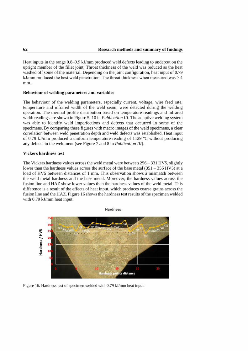
Research methods and summary of findings 62
Heat inputs in the range 0.8–0.9 kJ/mm produced weld defects leading to undercut on the
upright member of the fillet joint. Throat thickness of the weld was reduced as the heat
washed off some of the material. Depending on the joint configuration, heat input of 0.79
kJ/mm produced the best weld penetration. The throat thickness when measured was ≥ 4
mm.
Behaviour of welding parameters and variables
The behaviour of the welding parameters, especially current, voltage, wire feed rate,
temperature and infrared width of the weld seam, were detected during the welding
operation. The thermal profile distribution based on temperature readings and infrared
width readings are shown in Figure 5–10 in Publication III. The adaptive welding system
was able to identify weld imperfections and defects that occurred in some of the
specimens. By comparing these figures with macro images of the weld specimens, a clear
correlation between weld penetration depth and weld defects was established. Heat input
of 0.79 kJ/mm produced a uniform temperature reading of 1129 oC without producing
any defects in the weldment (see Figure 7 and 8 in Publication III).
Vickers hardness test
The Vickers hardness values across the weld metal were between 256 – 331 HV5, slightly
lower than the hardness values across the surface of the base metal (351 – 356 HV5) at a
load of HV5 between distances of 1 mm. This observation shows a mismatch between
the weld metal hardness and the base metal. Moreover, the hardness values across the
fusion line and HAZ show lower values than the hardness values of the weld metal. This
difference is a result of the effects of heat input, which produces coarse grains across the
fusion line and the HAZ. Figure 16 shows the hardness test results of the specimen welded
with 0.79 kJ/mm heat input.
Figure 16. Hardness test of specimen welded with 0.79 kJ/mm heat input.
Research methods and summary of findings 63
Using matched filler metal with high heat inputs can cause the weld metal strength to
have mismatch with the base metal and consequently causes lower hardness and strength
properties in the HAZ. The possible diffusion of alloying elements as impurities is also
detrimental to HAZ properties.
3.2.2 Publication IV
Research aims
To explore the applicability of an adaptive intelligent robotic GMAW process
in welding of S960QC UHSS, paying critical attention to the behavior of
welding parameters and their effects on the joint geometries.
To introduce S960QC UHSS as a potential lightweight material applicable
for Arctic structural construction.
This empirical study includes review of previous work on Arctic welding and
construction and the need to construct lightweight welded structures. The review work
gives an account of the requirements of weldable material for Arctic structural
construction. An illustration of a welded Arctic structure was presented to indicate the
various sections and parts that need to meet Arctic operation conditions and requirements.
S960QC material was introduced and suggested as a potential advanced steel applicable
for Arctic structural constructions.
The empirical work comprised investigation of S960QC UHSS material of 5 mm
thickness, welded in fillet-joint configurations with the adaptive robotic GMAW system
and the welding consumables mentioned earlier. Before welding, the S960QC material
was machined for 20 samples. The plates were tacked together, forming 10 samples of
fillet joints. For the welding experiments, 5 joints each were made to be welded in the PB
and PA welding orientation and positions respectively. During welding, the TPS, which
was attached and positioned at a distance of 30 mm behind the welding torch, was used
to measure thermal zones from the hot weld surface of the cooling weld seam during the
welding process. The adaptive welding system employed an existing artificial neural
network (ANN) to model the behavior of welding parameters and variables. Figure 17
shows the various fillet weld configurations used in the experiment.

Research methods and summary of findings 64
Fig. 17. Fillet weld configurations where a) is PB welding position and b) PA welding position.
The experimental work was done to determine the effects of varying heat inputs on the
hardness properties of the weld metal, weld fusion zones and the HAZ. Results were
compared with the base metal. Also, the effects of workpiece orientation on weld
penetration were determined. In addition, the work evaluated the behavior of welding
parameters and variables while using the intelligent adaptive welding system settings.
Out of the 10 tacked samples, only 2 samples were welded in the ANN environment.
After initial evaluation, only 8 samples (including the 2 samples welded in the ANN
environment) were utilized in analysis. The measured thermo-profile data were then
imported into MATLAB for further analysis of the behavior of the welding parameters
and variables. The welded specimens were etched with a 4% nital solution (95 ml
C2H5OH + 5 ml HNO3) to delineate the microstructure of the base metal and the
macrostructure features of the welds and the HAZs of the specimen. Light microscopy
and a Vickers hardness test machine were used for metallurgical and mechanical analysis
of the effects of heat inputs on various weld specimens. Table 10 shows the welding
parameters and variables used in the experiment. Detailed information about the welding
operation can be obtained from Publication IV.
Table 10. Welding parameters and variables for S960QC deep penetration welds.
Specimen
Heat Input Contact tip-to-work
distance (CTWD)
Torch angle
I (A) U (V) v
(mm/sec)
Electrode
stick out
mm
Wire
feed
rate
m/min
Torch
position
(0)
Torch
travel
angle
(0)
Torch
movement
technique
1 (PB ANN) 200.1 22.1 7.0 18.0 9.69 40 5 Pushing
2 (PA ANN) 202.2 22.3 7.0 18.0 9.37 90 0 Pushing
3 (PB 1) 213.6 24.3 7.0 18.0 10.31 40 5 Pushing
4 (PA 1) 232.1 26.2 7.0 18.0 10.27 90 0 Pushing
5 (PB 2) 204.7 26.2 7.0 18.0 8.90 40 5 Pushing
6 (PA 2) 211.7 26.1 7.0 18.0 8.87 90 0 Pushing
7 (PB 3) 195.7 24.6 7.0 18.0 8.90 40 5 Pushing
8 (PA 3) 208.9 24.6 7.0 18.0 8.90 90 0 Pushing
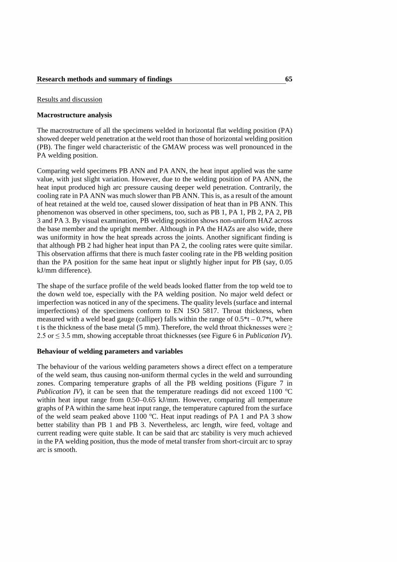
Research methods and summary of findings 65
Results and discussion
Macrostructure analysis
The macrostructure of all the specimens welded in horizontal flat welding position (PA)
showed deeper weld penetration at the weld root than those of horizontal welding position
(PB). The finger weld characteristic of the GMAW process was well pronounced in the
PA welding position.
Comparing weld specimens PB ANN and PA ANN, the heat input applied was the same
value, with just slight variation. However, due to the welding position of PA ANN, the
heat input produced high arc pressure causing deeper weld penetration. Contrarily, the
cooling rate in PA ANN was much slower than PB ANN. This is, as a result of the amount
of heat retained at the weld toe, caused slower dissipation of heat than in PB ANN. This
phenomenon was observed in other specimens, too, such as PB 1, PA 1, PB 2, PA 2, PB
3 and PA 3. By visual examination, PB welding position shows non-uniform HAZ across
the base member and the upright member. Although in PA the HAZs are also wide, there
was uniformity in how the heat spreads across the joints. Another significant finding is
that although PB 2 had higher heat input than PA 2, the cooling rates were quite similar.
This observation affirms that there is much faster cooling rate in the PB welding position
than the PA position for the same heat input or slightly higher input for PB (say, 0.05
kJ/mm difference).
The shape of the surface profile of the weld beads looked flatter from the top weld toe to
the down weld toe, especially with the PA welding position. No major weld defect or
imperfection was noticed in any of the specimens. The quality levels (surface and internal
imperfections) of the specimens conform to EN 1SO 5817. Throat thickness, when
measured with a weld bead gauge (calliper) falls within the range of 0.5*t – 0.7*t, where
t is the thickness of the base metal (5 mm). Therefore, the weld throat thicknesses were ≥
2.5 or ≤ 3.5 mm, showing acceptable throat thicknesses (see Figure 6 in Publication IV).
Behaviour of welding parameters and variables
The behaviour of the various welding parameters shows a direct effect on a temperature
of the weld seam, thus causing non-uniform thermal cycles in the weld and surrounding
zones. Comparing temperature graphs of all the PB welding positions (Figure 7 in
Publication IV), it can be seen that the temperature readings did not exceed 1100 oC
within heat input range from 0.50–0.65 kJ/mm. However, comparing all temperature
graphs of PA within the same heat input range, the temperature captured from the surface
of the weld seam peaked above 1100 oC. Heat input readings of PA 1 and PA 3 show
better stability than PB 1 and PB 3. Nevertheless, arc length, wire feed, voltage and
current reading were quite stable. It can be said that arc stability is very much achieved
in the PA welding position, thus the mode of metal transfer from short-circuit arc to spray
arc is smooth.

Research methods and summary of findings 66
On the contrary, the behaviour of welding parameters as observed from PA ANN and PB
ANN show unstable curves compared to other specimens. Figures 18 and 19 give a clearer
view of the behaviour of the welding parameters (see Figure 7 of Publication IV).
Although arc length and wire feed rate were quite stable, the severe fluctuations in
voltage, current, and heat input readings could be a result of disturbances in the adaptive
welding system. Such disturbances may have influenced the amount of heat input
supplied during welding, thus keeping the weld seam temperature below 1100 oC.
Secondly, such disturbance might be because the existing ANN system did not
compensate or try to modify the mode of metal transfer from short-circuit arc to spray
arc. It could also be because of lack of learning data or a compensating behavior to match
target conditions of the ANN system. Generally, the driving forces in GMAW
(electrostatic force, Marangoni force, buoyancy force, inertia, surface tension, and
viscosity) might have influenced the behaviour of the welding parameters and variables
in the different welding positions.
PA ANN
Figure 18. Behavior curves of welding parameters and heat input of specimen PA ANN.

Research methods and summary of findings 67
PB ANN
Figure 19. Behavior curves of welding parameters and heat input of specimen PB ANN.
Vickers hardness test
The Vickers hardness of the base metal varied between 351–356 HV at a load of HV5
between distances of 1 mm. The Vickers hardness values across the surface of the weld
metal was found to be similar in both PA ANN and PB ANN. The highest hardness values
obtained ranged between 375–397 HV. However, at the fusion boundaries, the hardness
values of PA ANN dropped to about 295 HV to the left side and 303 HV to the right side
of the joint geometry as shown in Figure 8 of Publication IV. Notably, at the fusion line
of PB ANN, there was no significant drop in hardness, as depicted in Figure 9 of
Publication IV.
At the HAZs, a drop in hardness was recorded in both welding positions. PA ANN
recorded a more progressive drop in hardness towards the base metal. Considering the
heat input applied in PA ANN and PB ANN, the maximum percentage drop in hardness
across the fusion boundaries to the base metal is about 26 % to 24 %, respectively (using
minimum hardness values). It can be seen from the graph of PA ANN from Figure 7 of
Publication IV that when heat input was within the range of 0.50–0.65 kJ/mm, the
temperature fluctuation reading did not peak above 1100 oC. This could be a result of the
welding parameters being modified by the ANN system.
Comparing PA 3 and PB 3, it can be seen in Figure 10 and Figure 11 of Publication IV
that PB 3 recorded higher hardness values at the surface of the weld metal than PA 3.
Considering the heat input applied in PA 3 and PB 3, the maximum percentage drop in

Research methods and summary of findings 68
hardness across the fusion boundaries to the base metal is about 21% to 16%, respectively
(using minimum hardness values). However, in PA welding positions, that is Figure 8
and Figure 10 of Publication IV, the drop in hardness is quite uniform from the HAZ to
the base metal on both sides of the welded joint. Hardness values across the surface of
the weld metal is uniformly spread due to the flatness of the weld bead profile. In PB
welding positions, that is Figure 9 and Figure 11 of Publication IV, a drop in hardness is
more prone to the upright member than the base member, especially at the fusion
boundary and in the HAZ. Although there is progressive drop in hardness towards the
base metal, the upright member experienced greatest hardness drop.
Microstructure
The microstructure formed in specimens welded in the PA position is different from
specimens welded in the PB position. The microstructure of the weld metal produced in
the PA welding position is uniformly mixed bainite and martensite, as shown in Figure
20. However, the microstructure of the weld metal produced in the PB welding position
is non-uniformly mixed, as shown in Figure 21. It is known that the electromagnetic force
enhances mixing in the weld pool, causing liquid metal to flow downward in the middle
of the weld pool and forming a counterclockwise circulation loop along the central
longitudinal plane. However, at the top surface of the weld pool, the Marangoni force
drives the melt from the center to the edge of the weld pool along the fusion boundary
(Kou and Wang, 1986; Kumar and DebRoy, 2007). It can be said that, in the PA position,
the combined forces of the electromagnetic and Marangoni produced a uniform mixing
pass. However, in the PB position, the Marangoni force was stronger than the
electromagnetic force so it could not sufficiently cause molten pool mix but rather drove
the molten pool from the center to the edge of the weld pool along the fusion boundary.
Figure 20. Micrograph of specimen PA ANN: a) HAZ of the upright member, b) weld metal, c)
HAZ of the base member.
(a) (b) (c)
100 µm 100 µm 100 µm
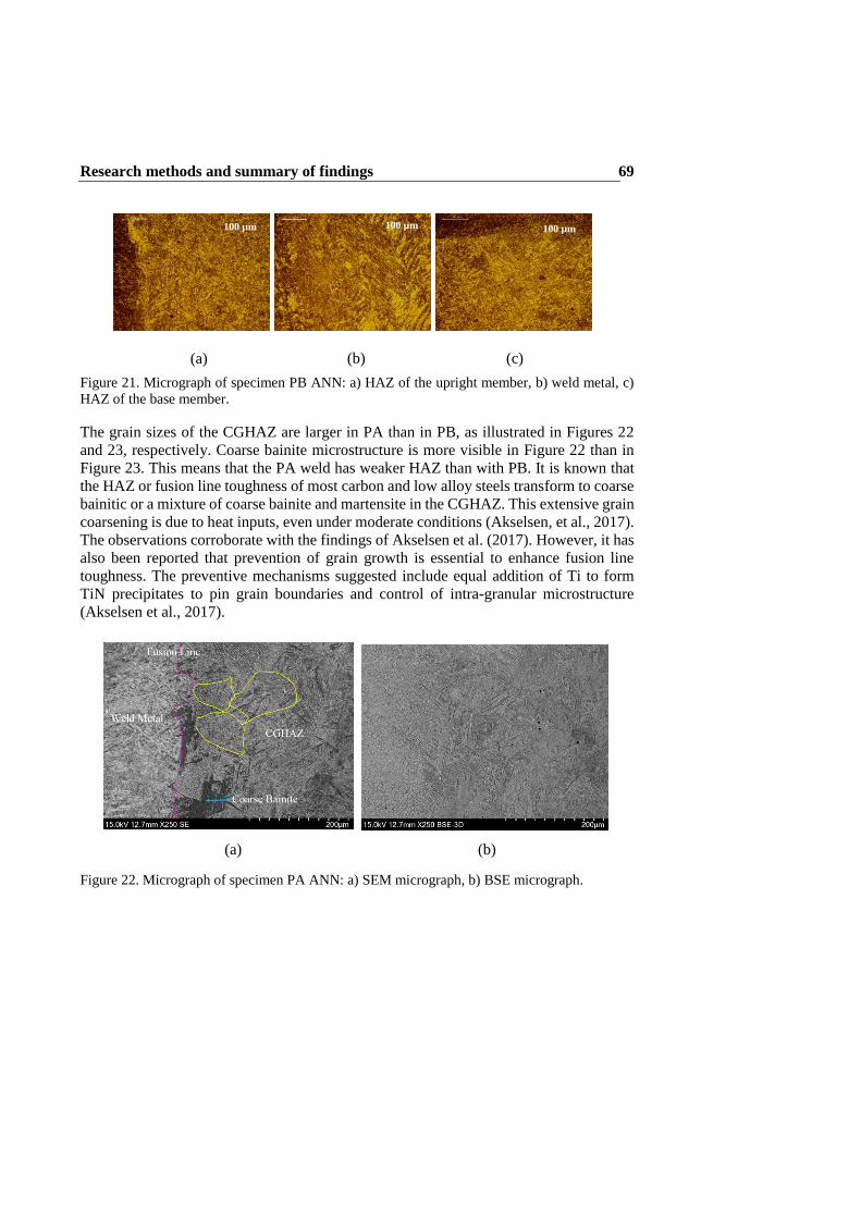
Research methods and summary of findings 69
Figure 21. Micrograph of specimen PB ANN: a) HAZ of the upright member, b) weld metal, c)
HAZ of the base member.
The grain sizes of the CGHAZ are larger in PA than in PB, as illustrated in Figures 22
and 23, respectively. Coarse bainite microstructure is more visible in Figure 22 than in
Figure 23. This means that the PA weld has weaker HAZ than with PB. It is known that
the HAZ or fusion line toughness of most carbon and low alloy steels transform to coarse
bainitic or a mixture of coarse bainite and martensite in the CGHAZ. This extensive grain
coarsening is due to heat inputs, even under moderate conditions (Akselsen, et al., 2017).
The observations corroborate with the findings of Akselsen et al. (2017). However, it has
also been reported that prevention of grain growth is essential to enhance fusion line
toughness. The preventive mechanisms suggested include equal addition of Ti to form
TiN precipitates to pin grain boundaries and control of intra-granular microstructure
(Akselsen et al., 2017).
Figure 22. Micrograph of specimen PA ANN: a) SEM micrograph, b) BSE micrograph.
(a) (b) (c)
(a) (b)
100 µm 100 µm 100 µm

Research methods and summary of findings 70
Figure 23. Micrograph of specimen PB ANN: a) SEM micrograph, b) BSE micrograph.
It should be noted that the black dots on both the SE and BSE micrographs are dirt
particles and are not related to the properties of the microstructures.
The illustration in Figure 24 shows a graphical description where grain growth prevention
and intra-granular ferrite promotion causes a shift in the microstructure from coarse upper
bainite to fine intragranular ferrite, resulting in a narrower CGHAZ. It has been presented
that intra-granular nucleation occurs due to particles (Kojima, et al., 2004; Suzuki, et al.,
2005), which can be oxides, sulfides, Ca, Mg or Ti, or high temperature stable nitrides
(TiN), of size from 10 nm to 0.5 μm (Akselsen, et al., 2017).
Figure 24. Possible microstructural changes under HAZ grain growth control. Modified. (Suzuki,
et al., 2005).
(a) (b)

Research methods and summary of findings 71
Table 11. EDA compositional analysis of PA ANN and PB ANN weldments.
EDS
compositional
analysis
C K Cr K Mn K Al K Si K Fe K Ni K Mo L Mg K
PA ANN 0.0/10 0.0/2.09 0.0/3.89 0.0/3.8 0.0/1.52 85/99 0.0/4.78 0.0/2.26
PB ANN 0.0/37 0.0/3.79 0.0/7.39 0.0/21 0.0/3.13 58/100 0.0/8.30 0.0/17 0.0/3.36
From Figure 23, it can be said that the CGHAZ shows an intra-granular microstructure
with narrower polygonal shaped ferrite in addition to the martensite-bainite mix. The
EDS compositional analysis performed revealed elemental variations in the weld metal,
as shown in Table 11. It was observed that the microstructure of specimen PB ANN had
traces of Mg. Therefore, the existence of Mg in the microstructure may have promoted
intra-granular nucleation as depicted in Figure 23.

Research methods and summary of findings 72
WQA model based on AIS 73
4 WQA model based on AIS
Among many practitioners there is a perception that implementation of robotic welding
systems in welding factories is tedious and time consuming. Some small and medium-
sized enterprises (SMEs) consider robotic welding uninteresting because their welding
production is done in batches based on contractual work. This means that programming
work has to be done for separate models of products before welding.
On the other hand, those welding companies who have made attempts to implement
robotic welding systems also face weld quality related challenges. These challenges stem
from the basic functionalities of robots. That is to say, robot manipulators are position-
controlled devices that can receive a trajectory and run it continuously, but repeatability
and precision is a challenge, as some margin of dimensional errors occur. Secondly, robot
manipulators have closed-loop controllers, and for this reason, the system does not allow
real-time position adjustment through programming by the user. Such robot controller
systems, therefore, do not provide programming platforms to handle tasks that require
complex techniques (learning, supervisory, monitoring, etc.). Additionally, remote
control of the robot manipulator done from an external computer is not applicable.
To alleviate the repeatability and precision challenges of the robot manipulator, frequent
calibration of the robotic welding system needs to be done, and this process does not fix
the problem in the long term. To solve the programming challenges inherent with robot
controllers, computational platforms suitable for handling complex non-linear operations
are needed, and systems for guidance and inspection to handle monitoring and control
tasks are also required.
For welding applications, the ability to start from one trajectory to another and essentially
have the means to adjust the trajectory in real-time, as a function of the observed
outcomes of the welding process, is very important. These functionalities and capabilities
expected of a robotic welding system are a critical demand from welding factories as they
pertain to welding productivity and quality assurance issues. Additional setup and
computational work is required to guarantee that robots perform as expected with the
required quality.
This chapter presents technological steps (assembly and programming capabilities) and
new approaches in developing a welding quality assurance (WQA) model based on
adaptive intelligent systems (AIS). The model is limited to the robotic GMAW process
because of the system integration components involved. The reasons for developing a
welding quality assurance model stem from the need to resolve the aforementioned
complexities and challenges and a desire to resolve similar challenges surrounding the
implementation of robotic GMAW systems in welding factories, be they in large or small
and medium enterprises (SMEs). Key intelligent technologies and architecture
(components, system integration protocols) for robotic GMAW will be discussed.
Additionally, there is consideration of adaptive intelligent GMAW as an enabling
technology for linking production across networks of companies.

WQA model based on AIS 74
4.1 Identification and selection of system hardware
The system hardware of an adaptive intelligent GMAW process should include
components illustrated in Figure 25. The operational functionalities of these components,
such as the sensors, robot manipulator, and monitoring systems, have been explained in
Chapter 2 of this work. These components are commercially available and some of the
components come with standardized programming languages, human-machine software,
and hardware interfaces.
Figure 25. Hardware components for adaptive intelligent GMAW system.
Robot
controller
Interface
panel
Sensors
Monitoring
device
Host computer /
Server with
software packages
GMAW
process

WQA model based on AIS 75
However, identifying and selecting the right components to meet welding manufacturing
and production needs is critical. When selecting the components, the following criteria
must be observed:
Components must have standardized features.
Components must be compatible with system integration protocols.
Components must be compatible with existing mechanical and engineering
software packages.
Components must have flexibility for configuration and programming.
Components must have ease of connectivity with other system components.
4.2 System integration protocols
System hardware identified in Figure 25 require suitable, appropriate and standardized
means to communicate with each other, either directly or indirectly, to execute single or
multiple tasks. For these reasons, different forms of system integration protocols for
diverse communication purposes are presented in this section.
A computer-based human-machine interface (HMI) is a fundamental requirement for
communication between devices and components made of electro-mechanical systems.
The teach pendant for robots basically serves the purpose of communicating input signals
between other hardware and software units for a specific function to be performed.
However, for such message signals to be communicated, system protocols like
programmable logic controllers (PLC), Ethernet, application programmable interface
(API) and fieldbus (IEC 61158) need to provide real-time distributed control and
connectivity.
When connectivity between components is established, system protocols like the I/O
controller (also called peripheral processor) receive the data and then communicate the
signals between the central processing unit (CPU) and the motherboard. For
communication between various software components, an API is required. For remote
control of the components, message based protocols like transmission control
protocol/internet protocol sockets (ICP/IP), and remote procedure call (RPC) sockets are
needed.
Figure 26 shows a schematic structure of the connectivity between the various adaptive
intelligent components and the system integration protocols. It can be seen that the HMI
is connected to the PLC or desktop computer/personal computer by an Ethernet.
However, a fieldbus is used to connect the HMI to the robot manipulator. Similarly, a
fieldbus is used to connect the PLC or computer to the various sensing and monitoring
systems. For connectivity between software systems of any of the components, an API
interface is used. For remote control of any of the components, either the TCP/IP
socket/server or RPC socket/server is used.
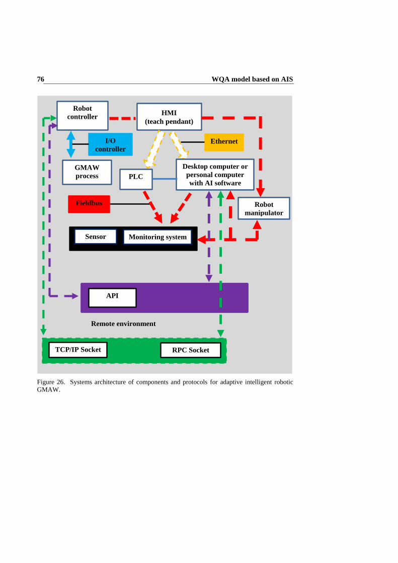
WQA model based on AIS 76
Figure 26. Systems architecture of components and protocols for adaptive intelligent robotic
GMAW.
HMI
(teach pendant)
Ethernet
PLC
Desktop computer or
personal computer
with AI software
Fieldbus
Sensor Monitoring system
Robot
manipulator
Remote environment
TCP/IP Socket RPC Socket
API
Robot
controller
GMAW
process
I/O
controller
WQA model based on AIS 77
4.3 The AIS based WQA model
Programming and modelling of welding data can be done in a number of different ways,
for instance: 1) by using existing engineering software packages like CAD/CAM with 3D
tools to generate weld data; or 2) by performing empirical tests for weld data collection
and exporting the data to software for further modelling and control. With software
packages like CAD, the CAD interface is used to programme and guide the robot welding
trajectories for execution of the welding operation in real-time (Chen and Wu, 2009).
However, the rigidity of the system does not allow real-time adjustment of parameters
and variables during welding. However, before or after welding, the welding parameters
can be adjusted off-line or even from a remote environment.
For the above reasons, the integration of software components like adaptive intelligent
systems to aid adjustment of welding parameters and variables through real-time
monitoring and control can provide optimum welding solutions, especially from the
perspective of weld quality and productivity. Adaptive intelligent systems, however,
require prior information or data for modelling and control of the welding. Therefore,
empirical tests are needed prior to designing the ANN model and control algorithm.
Design of the ANN model and control algorithm comprises the following stages:
Stage 1: Data collection
The data collection stage entails creation of a knowledge base from material samples of
welded metals. Figure 27 shows the schematics for data collection. With the adaptive
intelligent system in place, the knowledge base is automatically updated by aggregating
information generated during welding operations. The knowledge base includes
information such as welding parameters and variables, and seam data from the welding
process captured via the sensory and monitoring devices. The knowledge base can be
retrieved from a desktop computer as a Microsoft Excel document in most cases. This
process is vital because the transient details produced from the welding process have huge
amounts of weld and seam information, which is captured in a time domain, and which
needs to be validated through further modelling and control.

WQA model based on AIS 78
Figure 27. Schematics for data collection.
Robotic GMAW
process
Sensory and
monitoring device
captured data
Knowledge based
(data) in excel
document
Material samples are
welded according to
predefined welding
parameters and variables
(heat input, CTWD,
torch angle). However,
different forms of weld
configuration, welding
conditions (pre-heating),
and geometrical
parameters can be test
welded.
Weld data (weld pool
dynamics according to
voltage, current, wire
feed variations) and
seam data (geometrical
values according to
joint thickness, root gap
variations) are sensed
and monitored
according to predefined
values, including non-
defined values (errors).
Data from the welding
operation is retrieved
and displaced in
Microsoft Excel format.
The transient waveforms
produce huge weld and
seam information, which
requires further
processing and
validation.
Position adjustment of the
end effector
(tool position center - TPC)
Robot
controller

WQA model based on AIS 79
Stage 2: Data Validation
Welding data of the samples (in digital format) are examined by comparison with
corresponding physical samples. Samples with excessive defects are discarded, as is their
digital data. Those samples with minimal weld defects and acceptable according to
welding standards like ISO 5817 and ISO 15609 are included together in the knowledge
base with the good samples. This process helps in the creation of boundary conditions
and the setting of desired targets when training the data set in the ANN system. Therefore,
training of the data sets in the ANN system starts with an initiation process for data
validation. All the input data defined and all the output data defined are together fed into
the ANN system. Input data could be welding parameters like current, voltage and wire
feed rate, or geometrical parameters like throat thickness, depth of weld penetration, air
gap height, etc. Similarly, the output parameters can be either welding parameters or
geometrical parameters depending on the learning algorithms to be used. However, all
data items undergo an iteration process as part of the validation process to decrease data
errors. The iteration process takes several minutes depending on the number of data sets,
while the validation performance reaches a minimum error (mean square error). The
performance of the system is validated by following set targets of the ANN.
Figure 28 shows data validation performance of the iteration process and the regression
process. Iteration of the input-output data occurs in several time sequences. The
regression plots show the performance of the ANN by fitting the various data to targets
made with decisions by the ANN itself. Overfitting of the input-output data is bound to
happen if the data has a lot of variation. In such cases, more iteration and validation has
to be performed by the system through feeding back of error signals (re-training) into the
hidden layers. If the overfitting is high, some of the data must be discarded. The behavior
of the various welding parameters and variables can be analyzed by simulating the ANN
system.
Stage 3: ANN welding verification
After data validation, welding data from the decision-making of the ANN is verified. In
the verification process, the ANN welding data is used for empirical tests. If the tests
produce desirable results then the system is maintained. In this regard, the system is
assumed to be capable of adjusting itself automatically before, during and after the
welding operation to eliminate any welding flaws as defined in the limits. However, if
desirable results are not achieved, then Stage 2 is repeated.

WQA model based on AIS 80
Figure 28. Data validation performance of the iteration process and regression process.
Although these stages are time-consuming, the possibilities of using AI methods for real-
time operations could provide avenues for flexible offline welding as mentioned earlier.
The use of sensors alone to guide and control welding robots in real-time has encountered
some drawbacks leading to real-time malfunctions where the welding robot moves out of
joint limits, collides with objects in the work space, or moves into singularities due to
robot configuration changes (Cederberg, et al., 2002). With AI in place, the welding robot
can be controlled remotely by planning its motion, optimizing its path and trajectories,
and the robot can adapt to changes and unforeseen situations.
Most industrial robots are said to operate on CAR (Computer Aided Robotics) software
that enables modelling, simulation and programming of robot operations within CAD
Training data
(considered here
as Knowledge
data)
ANN system with back-
propagation Levenberg -
Marquardt algorithm
Welding data
from ANN
own decision-
making
Hidden
layers Input data Output data
Iteration Regression plots
Simulation environment

WQA model based on AIS 81
environments. To ensure optimum performance of real-time sensors with AI methods, a
virtual sensor model (virtual twin/digital twin) of the real sensor must be created and
implemented in the CAR virtual operating environment. The virtual sensor must be
validated statically and dynamically. The static approach is performed by matching the
virtual sensor with the real sensor through setup measurements and calibrations, while
the dynamic approach is done by comparing a welding operation performed in real-time
and a virtual work-cell created with a CAR application (Cederberg, et al., 2002).
Components to be welded are updated based on information provided by the virtual/real
sensor in real-time. By going through these approaches, a feedback loop is created that
makes full use of the sensor information (specific instructions used to define the robot
task as set of motions) and integrates it to the world model and application process
models. Real-time sensor feedback to the world model means that the information from
the sensors will actually update the world model, including updating object positions in
real-time as required or creating objects not included beforehand. Through this
mechanism, the use of sensors can be validated in a CAR environment as similar tests
should be made in a real physical setup (Cederberg, et al., 2002).
Development in remote welding has provided commercially available offline welding
applications. Some of these offline welding platforms have open architecture, which
needs to be customized to fit into the operationability of welding companies. Such offline
welding platforms with AI capabilities help to resolve robot collision challenges,
manipulator and end-effector reachability issues, and weld joint limit issues. Typical
examples of these offline welding platforms include those of Delfoi and Visual
Components. Together with other welding simulation platforms such as Simufact,
SYSWELD, robust offline welding operations can be achieved geared towards weld
quality and traceability.
Turnkey WQA Model
The turnkey WQA model in Figure 29 illustrates the steps required to design an adaptive
intelligent welding system and develop a case-specific WQA document for
implementation. The required steps and linkages are consolidated as preconditions for
successful development of the model. For example, without first configuring/calibrating
the controller and software according to systems specifications, the initial programming
of the robotic GMAW process cannot be accomplished. Therefore, the WQA model
provides generalized information to help large companies and especially SMEs to
strategically plan how to integrate and speed up the implementation of adaptive intelligent
welding systems into their manufacturing and production networks for weld quality
purposes.

WQA model based on AIS 82
Figure 29. A weld quality assurance model based on adaptive intelligent systems.
Component identification
and selection
Building the hardware
architecture
Welding experiments to
establish a knowledge base
Initial programming of
the robotic GMAW
process
Are components
response
acceptable?
Calibration and testing of
embedded controllers and
software
Identify and
select alternative
components
Discard
Modified set of
welding data by ANN
decision-making
No
Yes
No
Yes
Train input/output
parameters in the
ANN interface
Simulate system
response
Perform several
iteration by
retraining
input/output data
Does simulated
response produce
good validation
performance? No
Yes
Verify the
system by
empirical test
Any excessive
weld defects?
Modify control
strategy
Implement the ANN for
weld quality control
Does system
response meet
performance
specification
No
Yes
B
A
Key: (A) – Defects in the weldments are examined
mainly through DT or other NDT methods.
(B) – Welding is performed and possible defects are
evaluated mainly through DT or other NDT
methods.

Future research 83
5 Future research
Computational analysis of adaptive robotic GMAW of advanced steels needs to be
investigated further since this work did not delve deeply into this subject. Special
attention should be given to simulation tests on matched, undermatched and overmatched
filler materials in welding of advanced steels where heat inputs, CTWD and torch angles
are defined, visualized and observed with regards to their implications for weld quality
(strength, toughness, ductility, and microstructure nucleation and segregation properties).
The developed WQA-AIS model is made according to critical observation of robot
system integration and protocols, and a small number of empirical test observations.
Practical integration of the framework of the model with engineering design platforms
such as PDM systems to cover all factors related to welding manufacturing has not been
done. The WQA-AIS model, therefore, presents a generalized model, which needs further
study before it can be considered as acting as a proof of concept. Prior to implementation
of the WQA-AIS model, much further work is required, especially as regards selection of
system components, software, protocols, and intelligent systems.
5.1 Other research directions
This section presents general research directions based on the impact of AI and robotic
systems on technological, economical, educational, societal and environmental
advancement.
Networking of robot cells between large companies and SME’s:
The possibilities for welding companies to connect and synchronize their robot cells to
enhance welding throughput need investigation. Connection and synchronization can
enable construction of a network between robot cells and specific welding operations can
be performed even remotely. In addition, SMEs can network their robot cells to several
robots cells in the factories of large companies to lessen the amount of programming and
number of calibration tasks required before welding operations.
Collaboration between welding robots to expand job creation.
Several publications have stated that the use of robots for welding is a result of a global
shortage of welding personnel. This claim seems unconvincing because, based on
personal interactions and interviews, the unemployment rate among welding personnel
appears to be increasing. A possible reason for a shortage of welders in certain areas may
be because welding personnel have to go through several training courses, which are quite
expensive, before accreditation and before being able to accept work from ISO 9000
certified organizations. For this reason, most welding personnel keep to basic welding
skills when opening workshops offering welding services.

Future research 84
In the broader industrial context, there is a need to increase interaction between welding
personnel and robots, to expand job creation and the range of welding applications, and
to counteract the perception that robots steal human jobs. Robots should be seen as
assisting humans to do their jobs in a safer, more productive and less stressful manner
and as a way to improve quality. For SMEs with limited need for welding, welding robot
stations could be built around cities (like gas fuel station points). Each user would have
an ID card or a pass to go to the robot welding cell to order and weld a product. In such a
scenario, the robot welding stations would have an interface with several products and
specifications. Such robot welding cell stations could reduce unemployment among
welders by providing greater flexibility. Clearly, some welding skills would be required,
but SMEs would no longer have to set up specialist welding workshops with only limited
usage rates. Furthermore, barriers to setting up small manufacturing businesses would be
lowered by reducing the start-up capital required.
The use of universal robots in welding factory will promote human-robot collaboration
because such robots have low inertia and payloads, thus risks associated with safety will
be reduced. In addition, issues related with ergonomics is an area of concern. There is a
need for further investigations of these health and safety aspects.

Conclusions 85
6 Conclusions
The thesis began with a review of weld integrity aspects of advanced steels. The focus
was on weldability and service performance issues. These aspects constitute the key
criteria when considering the usability of advanced steels in welding manufacturing and
production. Heat input, cooling rate and filler material were considered when discussing
weldability aspects, and when examining service performance, aspects related to weld
geometry, material grade and crack growth were investigated. Other factors related to the
GMAW process were also examined, such as the interaction between the forces in heat
transfer and fluid flow. In addition to buoyancy, Marangoni and non-dimensional forces
and properties associated with the GMAW process, the electromagnetic force was noted
to play a major role in weld penetration and the formation of the weld pool. Also, sensing,
monitoring and risk assessment systems were reviewed, and welding of ultra high
strength steel (UHSS) material S960QC was evaluated from the control perspective to
enable creation of an artificial intelligence model. Welding standards such as EN ISO
5817 and ISO 15609-1 were used as guidelines in the evaluation process.
An experimental study examining the applicability of an adaptive intelligent robotic
GMAW system in welding of UHSS S960QC was presented. In addition, the study
presented a new weld quality assurance model based on adaptive intelligence systems
designed by utilizing the findings from the experimental study. The automation, robotics,
sensory, monitoring and artificial intelligent systems reviewed and utilized in the
experimental study aim to exploit the concept of Industry 4.0 and the “big data” involved
in the systems integration process. One aim of the work is to support welding companies,
both large and small and medium-scale enterprises (SME’s), in their decision-making and
assist them in the implementation and integration of adaptive welding systems in their
manufacturing and production networks. The new weld quality assurance model seeks to
facilitate digitization of weld quality and assurance processes to improve weld quality,
eliminate or reduce weldments with defects at the commissioning stages, generate a
digital history of the welding operation for future analysis, reduce rework, trace weld
defects digitally and in real-time, define and approve welding procedure specifications
(WPS) in digital formats, and increase productivity.
The concluding remarks are based on the research hypotheses formulated as claims in
chapter 1.8:
1. Advanced steels (structural steels having yield strength between 500-960 MPa and
thickness ≥ 5 mm and ≤ 10 mm) can be considered as lightweight steels.
Comparing the physical and mechanical properties of UHSS and conventional steels, the
potential savings from usage of UHSS become apparent; for example, the difference
between plate thickness, for the same load carrying capacity/ bending strength, of 10 mm
S 355 and 5 mm S960QC UHSS is about 66.7 %, and between weld seam volume about
95 % (Illustration in appendix Table 3).

Conclusions 86
2. When welding advanced steels, the selection of welding process and manufacturing
setup, heat input levels, cooling rate, filler materials and consumables, weld geometry,
weld orientation and control of the fusion process must be considered and critically
observed.
Risks associated with welding of advanced steels include HAZ softening, cracking and
embrittlement of the weld metal. HAZ softening is a result of microstructural changes
that occur due to high heat inputs and the rate of cooling. Heat input is consequently a
critical factor that affects significantly the strength and properties of welded joints of
advanced steels. For instance, if heat input is too low, there is a risk of lack of fusion, and
if the heat input is too high, the HAZ gets too wide as a result of grain growth and
diffusion of alloying elements. HAZ softening leads to ductility, strength, and toughness
problems, and the overall quality of welded joints may be affected. The risk of cracking
is chiefly caused by the choice of filler materials.
The use of matched, undermatched or overmatched filler materials and the heat inputs
involved must be critically considered when welding UHSS material with GMAW, as
evident from Appendix Table 1 and 2. Low heat inputs have a tendency to produce weld
defects like lack of fusion, incomplete penetration and poor weld quality. With moderate
heat inputs, welds of acceptable quality (toughness, strength and microstructure
properties) are produced. Unacceptable weld properties, softening of the HAZ and
deterioration of strength, toughness and ductility across the weld occur when high heat
inputs are used. The CTWD is an essential factor when considering the amount of heat
that directly hits the surface of the base metal and the extent of weld depth penetration.
The longer the electrode stick-out (between 18–28 mm), the less the effect of heat
intensity on the weld, eventually resulting in a deeper weld depth penetration.
The matched filler metal used in the fillet welds produced acceptable hardness properties,
especially when heat input was between 0.5–0.65 kJ/mm. It can be said that the hardness
properties of the weld metal agree with the strength properties of the base metal, thus
suitable for a complete joint penetration weld configuration due to the tensile properties
of the weld strength. However, undermatched filler metal may have produced weld
strength of acceptable hardness properties in relation to weld throat size and weld metal
strength for fillet welds according to heat input range and cooling times shown in
Appendix Table 1.
The orientation of the weld and the weld geometry have a significant influence on the rate
of cooling. In situations where deeper weld penetration is achieved, the rate of heat
dissipation may be slower and vice versa. A V-shaped fillet joint configuration produces
deeper weld penetration, but slower cooling rates, than an L-shaped fillet joint. For load
carrying purposes, the V-shaped fillet joint may be suitable to fulfil service requirements.
Similarly, the L-shaped fillet joint could be suitable from a load carrying perspective, but
the service performance must be evaluated.

Conclusions 87
3. An adaptive intelligent welding system is capable of providing real-time weld quality
data because of the self-monitoring and control features embedded in the system.
Weld and seam data captured by sensory and monitoring systems integrated with the
robotic GMAW process provide the means for real-time weld quality assurance data.
Weld information is captured in the time domain and could be visualized during or after
the welding process. Important parameters and variables of the welding process such as
welding current, voltage, heat input can be accessed real-time and predictions of the
outcome of the final weld can be made. Also, during welding, modifications can be made
to the welding parameter and variables using the visualization opportunities provided by
the adaptive welding system. Moreover, the automatic computation and analysis of
temperature of the weld and width of the weld seam gives an indication whether the weld
being produced will be of good or bad quality. Temperature readings up to about 1350 oC
can be captured and defects such as discontinuity in the weld seam can also be captured
by means of the thermal cycle readings across the weld seam. Weld and seam data
captured as digital data and analysed in graphical forms correlates with macrographs
produced from the weld specimens. It is possible to control the weld and seam data during
welding, but not data related to unforeseen circumstances and dimensional distortion.
In addition to the limitation observed for the sensory and monitoring system, further
processing of the data cannot be done using the same system, although play-back options
are available. An intelligent system is always required for control purposes due to
uncertainties and unforeseen conditions during welding. The welding process can
produce sudden fluctuations in current and voltage values, leading to either high or low
heat input being supplied to the weld. With an ANN system is place, the behaviour of the
welding parameters and variables could be greatly influenced by modelling and
controlling the output of the welding process. System parameters and variables can be
smoothened and disturbances could be filtered off for efficient system response.
4. An adaptive intelligent welding system has the potential to be integrated with
engineering design and manufacturing tools (CAD/CAM programs). By creating
product data management (PDM) systems for fabrication of welded components,
modular adaptive intelligent welding systems can be made for each bill of material
(BOM) for fabricating specific products. Routines and modules in the welding process
can be made for each product, and weld quality will be achieved with high assurance.
The possible integration of an adaptive intelligent welding system with engineering
design platforms like CAD/CAM and PDM systems in welding manufacturing is
noteworthy. This approach could facilitate offline welding possibilities and enable further
modelling and control of welding parameters and variables. With such systems in place,
the number of practical welding trials can be decreased, thus reducing waste and
increasing productivity.
5. The proposed weld quality assurance model when implemented in factories of SME’s
and large companies will serve diverse purposes. Weld quality data in digitized format

88
can be achieved, digitized welding procedure specification (WPS) can be generated,
wide range of modular products can be manufactured, and linking information to
cloud-based systems for effective information sharing in welding operations can be
achieved.
The implementation of the WQA-AIS model in welding manufacturing factories will
facilitate digitization of weld quality and quality assurance processes in realizing the goals
of sustainable future factories. The weld and seam data collection, and validation and
verification process relies on digitization processes that can enhance analysis and
interpretation of data related to weld quality. In addition, the adaptive system can improve
communication, information sharing and can offer integration of product data information
for reliable manufacturing. The WQA-AIS model, however, presents a generalized model
which still requires further work to be considered a proof of concept. In particular, the
WQA-AIS model requires further studies on implementation issues such as selection of
system integration components, software, protocols and intelligent systems.

References 89
References
Akselsen, O.M., Lange, H.I., Ren, X., Alvaro, A., Nyhus, B. (2017). Evaluation of low
temperature toughness in welding of 420MPa steel for Arctic application. Proceedings
of the Twenty-seventh International Ocean and Polar Engineering Conference, San
Francisco, CA, USA, June 25-30, pp. 274-281.
Aikenhead, M.J., McDonald, A.J.S. (2003). A neural network face recognition system.
Engineering Applications of Artificial Intelligence, Vol. 16, pp. 167-176.
Al-Faruk, A., Hasib, Md. A., Ahmed, N., Kumar, U.D. (2010). Prediction of weld bead
geometry and penetration in electric arc welding using artificial neural networks. Int J
Mech Mechatron Eng, Vol. 10, pp. 19-24.
Amin, M. (1983). Pulse current parameters for arc stability and controlled metal transfer
in arc welding. Metal Construction, Vol. 15(5), pp. 272-278.
Andersen, K., Cook, G.E. (1990). Artificial neural networks applied to arc welding
process modelling and control. IEEE Transaction Industry Application, Vol. 26(9), pp.
824-830.
Balasubramanian, V., Ravisankar, V., Ramachandran, C.S., Muralidharan, C. (2009).
Selection of welding process for hardfacing on carbon steels based on quantitative and
qualitative factors. Int J AdvManuf Technol, Vol. 40, pp. 887-897.
Billingham, J., Sharp, J.V. (2003). Review of the performance of high strength steels used
offshore. Research report 105. Cranfield University School of Industrial and
Manufacturing Science, pp. 3.
Björk, T., Toivonen, J., Nykänen, T. (2012). Capacity of fillet welded joints made of
ultra-high strength steel, Weld World, Vol. 57, pp. 71-84.
Bolmsjö, G. (1997). Knowledge based systems in robotized arc welding. Knowledge
based systems - Advanced Concepts", Techniques and Applications, (Spyros
Tzafestas, editor). Chapter 17, World Scientific, pp. 465-495.
Bowditch, W.A., Bowditch, K.E. (1997). Welding technology fundamentals, 2 nd ed. The
Goodheart-Willcox company, Tinley Park, IL, pp. 64-82.
Burns, R.S. (2001). Advanced control engineering. Butterworth-Heinemann. A division
of reed educational and professional publishing Ltd. ISBN 0750651008.
Cederberg, P., Bolmsjö, G., Olsson, M. (2002). Robotic arc welding - trends and
developments for higher autonomy. Ind. Robot, Vol. 29, pp. 98–104
90
Chen, S.B., Wu, J. (2009). Intelligentized methodology for arc welding dynamical
processes: Visual information acquiring, knowledge modelling and intelligent control
of arc welding dynamical process. Vol. 29, pp.14.
Chen, W.J. (2004). Research on local autonomous intelligent welding robot system and
its remote control. Doctoral dissertation. Shanghai Jiao Tong University.
Cheon, J., Kiran, D.V., Na, S-J. (2016). CFD based visualization of the finger shaped
evolution in the gas metal arc welding process. International Journal of Heat and Mas
Transfer. Vol. 97, pp. 1-14.
Cho, D.W., Na, S.J., Cho, M.H., Lee, J.S. (2013). A study on V-groove GMAW for
various welding positions. Journal of Materials Processing Technology. Vol 213, pp.
1640-1652.
Cook, G.E., Andersen, K., Fernandez, K.R., Shepard, M.E., Wells, A.M. (1987). Electric
arc sensing for robot positioning control. Robotic Welding. Editor: J. D. Lane. IFS
Publications Ltd, UK, Springer-Verlag, pp. 181-216.
Dabiri, M., Skriko, T., Amraei, M., Björk, T. (2016). Effect of side grooves on plane
stress fracture behavior of compact tension specimens made of ultra-high strength
steel. Key Engineering Materials, Vol. 713, pp. 159-162.
Dabiri, M., Isakov, M., Skriko, T., Björk, T. (2017). Experimental fatigue
characterization and elasto-plastic finite element analysis of notched specimens made
of direct-quenched ultra-high strength steel. Proc. Inst. Mech. Eng., Part C, Vol. 231,
pp. 4209-4226.
Dabiri, M., Björk, T. (2017). Fatigue analysis of notched specimens made of direct-
quenched ultra-high strength steel under constant amplitude loading. Procedia
Structural Integrity, Vol. 5, pp. 385-392.
Essers, W., Walter, R. (1981). Heat transfer and penetration mechanisms with GMA and
plasma-GMA welding. Weld. J. Vol. 60, pp. 37-42.
Fridenfalk, M. (2003). Development of intelligent robot system based on sensor control.
Doctoral dissertation. Lund University, Dept. of Mechanical Engineering.
Fuller, R. (2000). Introduction to neuro-fuzzy systems: advances in soft computing.
Physica-Verlag, New York, Heidelberg.
Garašić, I., Kožuh, Z., Remenar, M. (2015). Sensors and their classification in the fusion
welding technology. Technical Gazette, Vol. 22:4, pp. 1069-1074.
Gyasi, E.A., Kah, P., Ratava, J., Kesse, M., Hiltunen, E. (2017). Study of adaptive
automated GMAW process for full penetration fillet welds in offshore steel structures,

91
Proc. 27th International Ocean and Polar Engineering Conference, San Francisco,
CA, USA June 2017, pp. 290-297.
Gyasi, E.A., Kah, P., Handroos, H., Layus, P., Lin, S. (2018). Adaptive welding of
S960QC UHSS for Arctic structural applications. International Review of Mechanical
Engineering, Vol. 12:4.
Hardt, D.E. (1984). Ultrasonic measurement of weld penetration. Welding Journal, Vol.
63(9), pp. 273-285.
Hemmilä, M., Laitinen, R., Liimatainen, T., Porter, D. (2005). Mechanical and
technological properties of ultra high strength optim steels. Rautaruukki Corporation,
Helsinki. Online:
http://www.oxycoupage.com/FichiersPDF/Ruukki_Pdf/English/Ruukki-Technical-
article-Mechanical-and-technological-properties-of-ultra-high-strength-Optim-
steels.pdf.
Hemmilä, M., Hirvi, A., Kömi, J., Laitinen, R., Lehtinen, M., Mikkonen, P., Porter, D.,
Savola, J., Tihinen, S. (2010). Technological properties of direct-quenched structural
steels with yield strengths 900 - 960 MPa as cut lengths and hollow sections.
Rautaruukki Corporation, Helsinki. Online:
https://oxycoupage.com/FichiersPDF/Ruukki_Pdf/English/Ruukki-Technical-article-
Technological-properties-of-direct-quenched-structural-steels.pdf.
Hill, P. M. (1991). Cutting and welding in naval construction. Welding and Metal
Fabrication, pp. 63-72.
Hirai, A. (2001). Sensing and control of weld pool by fuzzy-neural network in robotic
welding system. The 27th annual conference of the IEEE Industrial Electronics
Society, pp. 238-242.
Holmes, J.H., Sacchi, L., Peek, N. (2017). Artificial intelligence in medicine AIME 2015.
Artificial Intelligence in Medicine, Elsevier, pp. 1-2.
Howard, B.C., Scott, C.H. (2005). Modern welding technology (6th edition, Pearson
Prentice Hall, USA).
Huanca, C.E., Absi, A.S.C. (2010). Feasibility study of non-conventional parameters for
disturbance monitoring and detecting in short circuit gas metal arc welding. ABCM
Symposium Series in Mechatronics, Osa/vuosikerta 4, pp. 559-569.
International Federation of Robotics (2017). Executive summary world robotics 2017
industrial robots. Online:
https://ifr.org/downloads/press/Executive_Summary_WR_2017_Industrial_Robots.p
df. Accessed: 10.10.2017.

92
ISO 5817 Welding (2014). Fusion-welded joints in steel, nickel, titanium and their alloys
(beam welding excluded) - Quality levels for imperfections. International
Organization for Standardization, Geneva, Switzerland.
ISO/TR 18491 (2015). Welding and allied processes – Guidelines for measurement of
welding energies.
Jae-Woong, K., Jun-Young, L. (2008). A control system for uniform bead in fillet arc
welding on tack welds. J Mech Sci Technol Vol. 22, pp. 1520-1526.
Jesus, M. P. A., Matos, R., Bruno, F. C., Rebelo, C., Silva, L. S., Veljkovic, M. (2012).
A comparison of the fatigue behavior between S355 and S650 steel grades. Journal of
Construction Steel Research, Elsevier, Vol. 79, pp. 140-150.
Juan, W., Yajiang, L., Peng, L. (2003). Effect of weld heat input on toughness and
structure of HAZ of a new super-HSS. Bulletin Material Science, Vol 26, no 3, pp.
301-305.
Juang, S.C., Tarng, Y.S., Lii, H.R. (1998). A comparison between the back-propagation
and counter-propagation networks in the modelling of TIG welding process. J Mater
Process Technol, Vol. 75, pp. 54-62.
Kah, P., Pirinen, M., Suoranta, R., Martikainen, J. (2014). Welding of ultra high strength
steels, Advanced Materials Research, Vol. 849, pp. 357-365.
Kah P., Shrestha M., Hiltunen, E., Martikainen, J. (2015). Robotic arc welding sensors
and programming in industrial applications. International Journal of Mechanical and
Materials Engineering. Vol.10:13, pp. 1-16.
Kim, K.N., Lee, S.H., Jung, K.S. (2009). Evaluation of factors affecting the fatigue
behavior of butt-welded joints using SM520C-TMC steel. International Journal of
Steel Structures, Vol. 9, pp. 185-193.
Kim, I.S., Son, J.S., Lee, S.H., Yarlagadda, P.K.D.V. (2004). Optimal design of neural
networks for control in robotic arc welding. Robot Comput Integr Manuf, Vol. 20(1),
pp. 57-63.
Kou, S., Wang, Y.H. (1986). Weld pool convection and its effect. Welding Research
Supplement, March, pp. 63-70.
Kumar, A., DebRoy, T. (2007). Heat transfer and fluid flow during gas metal arc fillet
welding for various joint configurations and welding positions. Metallurgical and
Materials Transactions A, Vol. 38a, pp. 506-519.
93
Kumar, A., Zhang, W., Kim, C.H., DebRoy, T. (2005). A smart bi-directional model of
heat transfer and free surface flow in gas metal arc fillet welding for practising
engineers. Welding in the Weld, Vol. 49, pp.32-48.
Layus, P. (2017). Usability of the submerged arc welding (SAW) process for thick high
strength steel plates for Arctic shipbuilding applications. Doctoral dissertation,
Lappeenranta University of Technology. Acta Universitatis Lappeenrantaensis 742.
Li, J.P. (1997). Fundamental research on arc light sensing technology during welding
process. Doctoral dissertation, Harbin Institute of Technology.
Liu, W.Y., Wang, L., Liu, J.B., Zhang, Y.Y., Li, P.H., Yuan, G.L. (2007). Microstructures
and properties in simulated heat-affected zones of 685 MPa grade copper-bearing steel.
Proceedings of Sino-Swedish Structural Materials Symposium.
Lopez, B., Martin, C., Vinas, P.H. (2017). Special section on artificial intelligence for
diabetes. Artificial intelligence in medicine, Elsevier, pp. 26-27.
McFarlane, D., Sarma, S., Chirn, J.L., Wong, C.Y., Ashton, K. (2003). Auto ID systems
and intelligent manufacturing control. Eng Appl Artif Intel, Vol. 16:4, pp. 365-376.
Menaka, M., Vasudevan, M., Venkatraman, B., Baldev, R. (2005). Estimating bead width
and depth of penetration during welding by infrared thermal imaging, Insight, Vol. 47,
pp. 564-568.
Mendez, P.F., Eagar, T.W. (2003). Penetration and defect formation in high-current arc
welding. Weld. J. Vol. 82, pp. 296-306.
Meng, W., Li, Z., Huang, J., Wu, Y., Katayama, S. (2013). Microstructure and softening
of laser-welded 960 MPa grade high strength steel joints. Journal of Materials
Engineering and Performance. ASM International, Vol. 23, pp. 541.
Miller, D.K. (1997). Use undermatching weld metal where advantageous. Welding
Innovation. Vol. 14, number 1.
Mvola, B. (2017). Effects of adaptive GMAW processes: Performance and dissimilar
weld quality. Doctoral dissertation. Lappeenranta University of Technology. Acta
Universitatis Lappeenrantaensis 750, pp. 30-41.
Nadzam, J., Armao, F., Byall, L., Kotecki, D., Miller, D. (2014). Gas metal arc welding.
Online:www.lincolnelectric.com/assets/global/Products/...SuperArc-SuperArcL-
56/c4200.pdf.
Nagarajan, S., Chen, W.H., Chin, B.A. (1989). Infrared sensing for adaptive arc welding.
Welding Journal, Vol. 68(11), pp. 462-466.
94
Nele, L., Sarno, E., Keshari, A. (2013). Modelling of multiple characteristics of an arc
weld joint. Int J Adv Manuf Technol, Vol. 69, pp.1331–1341.
Nestor, O. (1962). Heat intensity and current density distributions at the anode of high
current, inert gas arcs. J. Appl. Phys. Vol. 33, pp. 1638-1648.
Nippon Steel and Sumitomo Metal. (2014). Steel plates A001en_04_2014f. Nippon Steel
and Sumitomo Metal Corporation, Japan. [Online]
http://www.nssmc.com/product/catalog_download/pdf/A001en.pdf.
Nomura, H. (1994). Sensor and control system in arc welding. Chapman & Hall. pp. 3-
5.
Norrish, J. (2017). Recent gas metal arc welding (GMAW) process developments: The
implications related to international fabrication standards. Weld World. Vol. 61, pp.
755-767.
Nykänen, E. (1994). Shipbuilding at Kvaerner Masa-Yards Helsinki New Shipyards.
Hitsautekniikka 5/94, pp. 20-23.
Owen, F. (2012). Control systems engineering a practical approach. USA, California
Polytechnic State University, pp. 1-25.
Pires, J.N., Loureiro A., Bölmsjo, G. (2006). Welding robots: Technology, system issues
and applications. Springer-Verlag London Limited. pp.180.
Pirinen, M. (2013). The effects of welding heat input on the usability of high strength
steels in welded structures. Doctoral dissertation, Lappeenranta University of
Technology. Acta Universitatis Lappeenrantaensis 514.
Porter, D. (2006). Development in hot-rolled high-strength steel, Nordic Welding
Conference, New Trends in Welding Technology, Tampere, Finland.
Rantalainen, T. (2012). Simulation of structural stress history based on dynamic analysis
Doctoral dissertation. Acta Universitatis Lappeenrantaensis 494, Finland.
Rodrigues, D.M., Menezes, L.F., Loureiro, A. (2004). The influence of the HAZ
softening on the mechanical behavior of welded joints containing cracks in the weld
metal”. Engineering Fracture Mechanics, Vol 71(13-14), pp. 2053-2064.
Rosheim, M. (1994). Robot evolution: The development of anthrobots. New York: John
Willey & Sons, 1994.
Ruukki Metals (2007). Hot rolled steel plates, sheets and coils – Processing of materials-
impact strength and through thickness properties. Helsinki.

95
Saaty, T.L. (1980). Analytical Hierarchy Process (McGraw-Hill, New York, 1980).
Suzuki, S., Ichimiya, K., and Akita, T. (2005). High tensile strength steel plates with
excellent HAZ toughness for shipbuilding—JFEEWEL Technology for Excellent
Quality in HAZ of High Heat Input Welded Joints. JFE Technical Report, No. 5, pp.
24-29.
Ushio, M., Mao, W. (1994). Sensors for arc welding: Advantages and limitations.
Transactions of JWRI, Vol. 23(2), pp.135-141.
Venkatraman B., Menaka M., Vasudevan, M., Raj, B. (2006). Thermography for online
detection of incomplete penetration and penetration depth estimation, In: Asia-Pacific
Conference on NDT, 5th–10th November, Auckland, New Zealand.
Wahab, M.A. (1998). The prediction of the temperature distribution and weld pool
geometry in the gas metal arc welding process. Journal of Materials Processing
Technology. Vol. 77, pp. 233–239.
Wang, J., Li, Y., Liu, P. (2003). Effect of weld heat input on toughness and structure of
HAZ of a new super-HSS, Material Science, Vol 26, No 3, pp 301-305.
Wang, S., Wan, J., Zhang, D., Li, D., Zhang, C. (2016). Towards smart factory for
industry 4.0: A self-organized multi-agent system with big data based feedback and
coordination. Comput Netw, Vol. 101, pp. 158-168.
Wang, W., Liu, S. (2002). Alloying and microstructure management in developing
SMAW electrodes for HSLA-100 steel. Welding Journal, Vol. 81, pp. 132-145.
WTIA TN 15 (1999). Welding Technology Institute of Australia. Quenched and tempered
Steels, Milsons point.
Yadav, N., Yadav, A., Kumar, M. (2015). An introduction to neural network methods for
different equations. Springer Briefs in applied sciences and technology.
Computational intelligence, Springer Science + Business Media B.V, Dordrecht.
Zeman, M. (2009). Properties of welded joints made of weldox 1100 steel. Welding
International, Vol. 23, pp. 83-90.
Zhong, R.Y., Xu, X., Klotz, E., Newman, S.T. (2017). Intelligent manufacturing in the
context of industry 4.0: A review. Engineering. Vol. 3, pp. 616-630.


APPENDIX
Table 1. Correlation of heat inputs and cooling rates of filler materials for UHSS material of 5
mm thickness.
Cooling time (t8/5) in seconds
Filler materials UHSS base metal
S960 QC
thickness 5 mm
Low Moderate High
Overmatched X X-Y Z Z Z Z Z Z
Matched X Y X-Y X-Y X-Y X-Y X-Y X-Y
Undermatched X-Y Y X-Y* X-Y* X-Y* X-Y* X-Y* X-Y*
Key:
- Low heat inputs (in the yellow region).
- Moderate heat inputs (in the green region).
- High heat inputs (in the orange region).
- X means – tendency to produce weld defects like lack of fusion, incomplete penetration
and poor weld quality.
- Y means – welds of acceptable quality (toughness, strength and microstructure
properties) are produced.
- Z means – Unacceptable weld properties, softening of the HAZ and deterioration of
strength, toughness and ductility across the weld occur.
- X-Y means – Weld properties between X and Y
- X-Y* means – Weld properties almost to Y.
0.0 10 15 20
0.3 0.4 0.5 0.6 0.7 0.8 0.9 1.0 1.1 1.2
Heat input, kJ/mm

Table 2. Types of filler metals and their effects on weld strength.
*E.g. Using 12.64 filler metal for S960QC
Undermatched
Undermatched filler metal produces lower
yield points resulting into less residual
stresses on the base metal. Although the
allowable strength level on the weld metal is
the lowest when compared with matched and
overmatched filler metals, the allowable
strength levels on the base metal is highest
since the weld metal controls the strength of
the joint.
*E.g. Using X96 filler metal for S960QC
Matching
Matched filler metal produces higher yield
points than undermatched filler metals, thus
resulting into higher residual stresses on the
base metal. Although the allowable strength
level on the weld metal is higher when
compared with undermatched filler metals,
the allowable strength levels on the base
metal is lesser in comparison with
undermatched filler metal. Nevertheless, the
strength level of the weld metal is equally the
same as that of the base metal.
*E.g. Using X90 filler metal for Weldox 700 E
Overmatched
Overmatched filler metal produces the
highest yield points when compared with
matched and undermatched filler metals.
Residual stresses on the base metal are
therefore very high. The allowable strength
level on the weld metal is higher when
compared with matched filler metals.
Nevertheless, the allowable strength levels
on the base metal is the lowest.
Filler metal 12.64
A5 = 26%
Measured fY = 580 MPa
Measure fu = 690 MPa
Filler metal X96
A5 = 14%
Measured fY = 990 MPa
Measure fu = 1245 MPa
Filler metal X90
A5 = 15%
Measured fY = 890 MPa
Measure fu = 950 MPa

Table 3. Comparison between UHSS and S355 steels based on plate thickness and acting forces.
Steel Grades
Maximum force to
cause material to
fracture at an angle of
30o
Fmax = 0.943btfy
Where b and t are the
width and thickness of
the plate, and fy (MPa) is
the yield strength of the
material.
Bending force
F = CRmbt2/W
Where Rm is tensile
strength, t is plate
thickness, C is a constant
whose magnitude is 1.2 –
1.5, b is the bend length
and W is the die gap.
*The size of the punch is not
considered, which leads to
under-estimation of the bending
force in the UHSS.
UHSS S960QC
120 X 80 X 5 mm
Fmax
= 0.943 x 80 x 5 x 960
= 362 kN
Bending force
= 1.5 x 960 x 1 x 52/ 1
= 36 kNm
S355
120 X 80 X 10 mm A5= 22%, hardness = 140 -190 HB, impact energy = 27J, ± 20o
Fmax
= 0.943 x 80 x 10 x 355
= 267 kN
Bending force
= 1.5 x 355 x 1 x 102/ 1
= 53 kNm

Table 4. Welding Procedure Specification (WPS) description according to ISO 15609-1.
Welding Procedure Specification:
WPQR No.: Method of Preparation and Clearing
Manufacturer: Parent Material Designation:
Mode of metal transfer: Material thickness (mm):
Joint type and weld type: Outside diameter (mm):
Weld preparation details (sketch)* Welding position:
Joint Design Welding Sequences
Welding Details
Run Welding
process
Size of
Filler
Material
Current
(I)
Voltage
(V)
Type of
Current/Polarity
Wire
Feed
Rate
Run Out
Length/Travel
Speed
Heat
Input
Filler material designation and make:
Any special baking or drying:
Designation gas/flux: -Shielding Other information*, e.g.
-Backing Weaving (max. width of run):
Gas flow rate -Shielding Oscillation: amplitude, frequency:
-Backing Pulse welding details:
Tungsten electrode type/size: Distance contact tube/work piece:
Details of back gouging/backing: Plasma welding details:
Preheat temperature: Torch angle:
Interpass temperature:
Post-heating:
Preheat maintenance temperature:
Post-weld heat treatment and/or ageing:
(Time, temperature, method:
Heating and cooling rates*):
……………………………………………………………………
Manufacturer
(Name, signature, date)

Publication I
Gyasi, E.A. and Kah, P.
Structural integrity analysis of the usability of high strength steels (HSS)
Reprinted with permission from
Reviews on Advanced Materials Science
Vol. 46, pp. 39-52, 2016
© 2016, Advanced Study Center, CO. Ltd.


39Structural integrity analysis of the usability of high strength steels (HSS)
© 2016 Adva]ced Study Ce]ter Co. Ltd.
Rev. Adv. Mater. Sci. 46 (2016) 39-52
Corresponding author: E. A. Gyasi, e-mail: [email protected]
STRUCTURAL INTEGRITY ANALYSIS OF THE USABILITYOF HIGH STRENGTH STEELS (HSS)
E. A. Gyasi and P. Kah
Laboratory of Welding Technology, Mechanical Engineering Department,Lappeenranta University of Technology, P. O. Box 20, 53851 Lappeenranta, Finland
Received: November 05, 2015; in revised form: July 11, 2016
Abstract. High stre]gth steels HSS) of yield stre]gth betwee] 500 – 900 MPa are used i]industries such as shipbuilding and automobile manufacturing and for applications like offshorestructures due to their advantageous physical and mechanical properties, which surpass thoseof conventional steels. Although the strength levels of HSS make structural weight reductionpossible, and corresponding reduction of transportation and other manufacturing costs, theusability of high strength steels is negatively affected by issues such as a susceptibility to crack-ing and heat affected zone (HAZ) softening due to the effects of welding heat input. These qualityproblems can have a detrimental effect on the structural integrity of HSS welded structures. Thispaper critically reviews the usability of high strength steels from a structural integrity viewpointdrawing attention to the key issues involved. A decision-making tool for risk assessment basedon the analytical hierarchy process (AHP) is presented and its suitability for evaluation of struc-tural integrity risk in welded HSS structures. Challenges regarding HSS usability from the weldabilityand service performance perspectives are related to factors such as heat input, cooling rate andtype of filler material; and weld geometry and crack propagation, respectively. The potential of anon-line welding process monitoring system incorporating AHP as part of the risk assessmentprocess is noted. Additionally, the study identifies a need for further research on neuro-fuzzynetwork systems as an optimization mechanism for mitigating potential flaws in welding usabil-ity of HSS and its variants (advanced high strength steels, and ultra-high strength steels).
1. INTRODUCTION
High Strength Steels (HSS) are in increasing de-mand since their superior physical and mechanicalproperties to conventional steels (e.g. grade S235,S355, etc.) permit their use in a wide range of in-dustrial applications. However, a number of unfavor-able characteristics, like susceptibility to crackingand heat affected zone (HAZ) softening, due to theeffects of welding, limit the usability of high strengthsteels [1,2]. These undesirable characteristics canlower the integrity of structures constructed of HSS,making the structures weak, unstable and prone tofatigue failure, which in-turn can lead to catastrophicfailure in some scenarios. It has been observed that
HSS structures are sensitive to fatigue phenomenaas a result of the welding heat input [3].
To be able to alleviate the detrimental effects ofwelding of HSS, thorough investigation of weldabilityand service performance, including effective, efficientand rigorous risk assessment, is required. This pa-per presents a framework that evaluates essentialfactors and processes in determining the structuralintegrity of welded HSS. As shown in Fig. 1, manyelements associated with weldability, service per-formance, machine factors and human factors haveeffects on structural integrity. Also as depicted inFig. 1, these elements need to be evaluated throughstructured risk assessment, for example, by use of

40 E.A. Gyasi and P. Kah
a decision-making tool such as the analytical hier-archy process (AHP).
In addition to the risk assessment process, theframework includes on-line process monitoring andfailure analysis procedures. These procedures serveas a new approach to facilitate the risk assessmentprocess. The elements, factors, processes and pro-cedures presented in the framework are elaboratedin the paper.
Furthermore, the cross link shown in Fig. 1 rep-resents a feedback loop system between the ef-fects on structural integrity and the entire risk as-sessment and control process. Based on this crossli]k “feedback loop system”, the adoptio] of a neuro-fuzzy network system approach is proposed as anoptimization mechanism for eliminating potentialflaws when welding HSS. This paper attempts tobridge a research gap observed in the literature per-taining to risk assessment of HSS for structuralapplications as well as expanding the knowledgebase on the consequences of welding on fatigue inHSS welded structures.
2. STRUCTURAL INTEGRITY OF HSS
2.1. Weldability
HSS are often produced and delivered as quenchedand tempered (Q&T) or thermo-mechanical con-trolled process (TMCP) steels. These steels are
Fig. 1. Schematic framework for determining sound structural integrity in welded HSS structures.
distinct due to their chemical properties, which aremainly determined by the addition of particular al-loying elements, such as aluminum, vanadium, sili-con, zirconium, and copper, to increase or decreasehardenability. The chemical composition of Q&Tsteels may contain alloying elements such asnickel, titanium, molybdenum and boron, and thustheir qualities may differ slightly from those of TMCPsteels. Moreover, carbon equivalent values (CEV)for Q&T and TMCP steels also differ significantlydue to the carbon content, which contributes greatlyto the hardness of the steels [4]. Table 1 showsexamples of chemical composition of Q&T andTMCP steels.
Some typical Q&T steels for structural applica-tions are the steel grades S500, S550, S620, S690,S890, and S960 [EN10025-6] [5]. Q&T high strengthstructural steels (usually up to S690) are ideal forapplications with heavy sections and heavy liveloads (e.g. long span bridges), where weight reduc-tion is important.
Generally, the alloying composition of Q&T steelsincreases with increasing plate thickness in orderto ensure sufficient hardening of the plate in the coreregion. Therefore, the CEV of a Q&T plate increaseswith increasing thickness. It is known that Q&T andTMCP steels have fairly similar physical propertiessuch as good strength to weight ratio and high loadcarrying capacity [5,6].

41Structural integrity analysis of the usability of high strength steels (HSS)
Table 1. Chemical composition of Q&T and TMCP steels for low temperature applications.
Typical Thickness (mm) CE IIW Typical Mechanical YieldComposition (wt.%) Strength / CVN range
TMCP Steels C, Mn, Si, S, P, Nb, 30 0.35 400 MPa/190J @ -40°CV, Al, Cu, Ni, Cr 32 - 398 MPa/300J @ -20°C
32 0.32 400 MPa/>300J @ -20°C30 0.37 460 MPa/220J @ -40°C
Q&T Steels C, Mn, Si, S,P, Nb, 6-140 0.81 550 – 690 MPa/80J @ -84°CV, Al, Ti, Cu, Ni, Cr, 30 0.45 450 MPa/>35J @ -40°CMo, B 50-64 0.43 (Ti) 480 MPa/>40J @ -40°C
50 0.64 690 MPa/>40J @ -40°C(Ti, Mo, B)
30 0.64 (B) 960 MPa/>40J @ -40°C
Table 2. Thermal cycles influencing HAZ softening of HSS characteristics and examples.
Exploring the use of HSS makes it possible toreduce construction weight and cost, lower con-sumption of welding consumables, and reduce weld-ing time as a result of decreased thickness of thematerial [7,8].
Conventional welding processes such asshielded metal arc welding (SMAW), flux cored arcwelding (FCAW), gas metal arc welding (GMAW),and submerged arc welding (SAW) have proven tobe suitable for welding HSS. Nevertheless, the char-acteristic softening phenomenon due to uncontrolledheat input and cooling time [9] impairs tensile
strength [10-11] and joint strength properties [6,12],as well creating weld crack tendencies, and leavesHSS weldability issues unsolved. Table 2 illustratesthe thermal cycles influencing the heat affected zonesoftening phenomenon of HSS.
The risk of cracking and HAZ softening phenom-ena during welding of HSS places limitations on boththe maximum and minimum total heat input, as il-lustrated schematically in Fig. 2 [14]. The shadedregion shows the permissible heat input. The risk ofcold cracking and excessive hardening, as depictedon the left side of the diagram, occurs when mini-

42 E.A. Gyasi and P. Kah
mum heat inputs are used. Also, loss of strengthand hardness due to over-tempering and possibleloss of toughness as a result of re-transformation toupper bainitic microstructures during cooling occurswhen high or maximum heat inputs are used [13,14].
For Q&T steels, the harder the microstructure,the greater is the cold cracking risk [15]. For TMCPsteels, due to their low carbon equivalent content(CEV), there is high tendency of decreased weldedjoint strength as a result of the softening of the HAZcaused by uncontrolled heat input. As an importantvariable governing cooling rate/time, the higher theheat input the slower the cooling rate. This phe-nomenon has a key role in the phase balance andmechanical properties of HAZ and the weld [16]. Inpractice, the cooling rate is dependent on many fac-tors: heat input, process efficiency, material prop-erties, preheat temperature, material thickness andwire feeding rate [17,18]. The total weld heat inputinvolving preheat temperature, interpass tempera-ture and arc energy input has to be considered whendetermining appropriate cooling times [14].
It has been shown [16] that martensite-bainitemicrostructural transformation is prevalent whenwelding HSS of the Q&T type under appropriatewelding conditions and when using suitable fillermaterials. For TMCP steels, a ferrite-bainite micro-structure is obtained. Therefore selection of under-matched, matched or over-matched filler materialmust be done with accuracy since wrong judgmentscan lead to low toughness properties in the HAZ orweld metal (dilution of the base metal and the fillermaterial) and consequently affect the microstruc-tural transformation. Nevertheless, the microstruc-tural formations in both Q&T and TMCP steels ex-
Fig. 2. Total weld heat input relations for weldingQ&T steels characteristic. Reprinted with permis-sion from Welding Technology Institute of Australia,Quenched and Tempered Steels, WTIA (TechnicalNote 15, Milso]s Poi]t, 1985). © 2016 WTIA.
hibit excellent ductility, and higher strength andtoughness properties [16]. Therefore to ensure soundstructural integrity of a welded HSS structure, suchmicrostructures aforementioned should be obtained.Considering cold cracking in Q&T steels, low hy-drogen filler materials are used to prevent or limitthe introduction of hydrogen into the welded jointsor HAZ [19]. Furthermore, it has been reported thatwelding of Q&T steels often require pre-weld or post-weld heat treatment in order to also minimize sus-ceptibility of hydrogen-induced cracking therebypromoting sound microstructural formation [20]. Onthe other hand, TMCP steels exhibit sufficientstrength and toughness, and they do not requirehot working and post-weld heat treatment (PWHT),as they can create strength problems [21-23]. How-ever, service performance conditions also revile theneed to lessen weldability problems of HSS.
2.2. Service performance
The usability of HSS in the contest of service life-time is influenced by effects of welding. For thisreason, factors related to service performance ofHSS, such as static strength, ductility, fatigue life,and corrosion resistance require particular attention,because, as a structural detail, a weld is initiallyprone to fatigue as a result of fatigue stresses,discontinuities, and welding defects. Therefore pre-existing cracks from welding defects promote crackformation, which has repercussions on fatigue life.Welded HSS have been observed to be more sensi-tive to fatigue phenomenon and more likely to expe-rience fatigue failure [3].
Traditionally, fatigue life has been expressed asthe total number of stress cycles required for a fa-tigue crack to initiate and grow large enough to pro-duce catastrophic failure [24]. Generally, fatiguephenomena occur as a result of fatigue stressesand discontinuities. Fatigue stress therefore in-creases as a result of stress components (nominalstress, bending stress, nonlinear stress peak)whereas discontinuities occur mainly due to effectof notches, crack initiation, and crack propagation.Fatigue failure is common in welded structures dueto notch geometries, which act locally as stressconcentrator. Thus, the fatigue life of a notched speci-men depends on the material and the notch geom-etry [3]. On the other hand, the geometry of a welddetermines its fatigue strength whereas the staticstrength of the parent material (and of the filler metal)is of less importance in determining the fatiguestrength [25,26].

43Structural integrity analysis of the usability of high strength steels (HSS)
Fig. 3. Phases of crack growth in fatigue cracking. Reprinted with permission from T. Rantalainen, Simula-tion of Structural Stress History Based on Dynamic Analysis (Acta Universitatis Lappeenrantaensis 494,Fi]la]d, 2012). © 2012 Acta U]iversitatis.
Structural fracture and failure is divided into twophases: the crack initiation phase and the crackpropagation phase. In the crack initiation phase, oneor more small cracks begin to form in the material,while in the crack propagation phase, the initial crackpropagates until it results in the failure of the struc-ture. Fig. 3 illustrates the three fatigue crackingstages. Microcrack initiation and microcrack growthare together referred to as Stage I crack growth.Once the Stage I crack achieves a critical length, itwill become a Stage II crack. In stage III, crack growthchanges direction and begins propagating normalto the maximum principal stress [3].
For loaded welded structures, fatigue damageis caused by the simultaneous action of cyclicstress, tensile stress and plastic strain. If any oneof these three elements is not present, a fatiguecrack will not initiate and propagate [24]. Cyclicstress initiate cracks, the tensile stress propagatescrack growth, and together they produce plasticstrain. In the case of a brittle material, the releasedenergy exceeds the absorption capacity of the ma-terial, and the crack propagation continues unsta-bly, and hence the material fractures in a brittle way[3].
Some studies have shown that the fatiguestrength of steels is usually proportional to their yieldstrength [27]. This generalization is not true for allcases because for high tensile strength values,toughness and critical flaw size may govern ulti-mate load carrying ability. Therefore, fatigue testsperformed on small specimens are not always suf-ficient to precisely establish the fatigue life of a part.These small specimen tests are, however, usefulfor rating the relative resistance of a material to cy-
clic stressing and ascertaining the baseline proper-ties of the material.
For example, a recent experiment compared thefatigue behavior of mild steel (S355) and highstrength steel (S690) [28]. The two specimens wereexperimented using strain control, fatigue crackpropagation and cyclic elastoplastic tests. The re-sults indicated that although the S690 steel gradeshowed higher resistance to fatigue crack initiationthan the S355 steel, its resistance to fatigue crackpropagation was lower. Fig. 4 compares the fatiguecrack propagation rates between the two steels. Itis evident that the S690 steel shows the highestfatigue crack growth rates for all four tested stressratios of 0.0, 0.25, 0.50, and 0.75 respectively. Thisfinding was explained as being due to the finer grainof the S690 steel promoting fatigue crack propaga-tion.
These results confirm an inverse dependencebetween static strength and fatigue life of HSS.Therefore utilizing HSS for applications where fa-tigue crack propagation is the governing phenom-enon requires critical design consideration [28].
The superior fatigue crack initiation resistanceof the HSS may not be relevant in HSS welded joints,since fatigue life is often affected by fatigue crackpropagation. Data found in literature shows that fa-tigue resistance of welded high and ultra-highstrength steel structural parts is similar to that ofconventional steels with much lower yield stress[29].
This is due to short fatigue crack initiation pe-riod caused by stress concentration and weld de-fects. Nevertheless, crack propagation plays a keyrole on fatigue life [30]. Therefore when subjecting
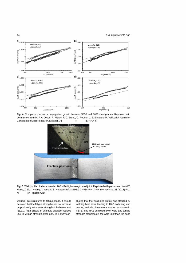
44 E.A. Gyasi and P. Kah
Fig. 4. Comparison of crack propagation growth between S355 and S690 steel grades. Reprinted withpermission from M. P. A. Jesus, R. Matos, F. C. Bruno, C. Rebelo, L. S. Silva and M. Veljkovi // Journal ofConstruction Steel Research, Elsevier. 79 2012) 140. © 2012 Elsevier Ltd.
Fig. 5. Weld profile of a laser-welded 960 MPA high strength steel joint. Reprinted with permission from W.Meng, Z. Li, J. Huang, Y. Wu and S. Katayama // JMEPEG 23:538-544, ASM International. 23 (2013) 541.© 2014 ASM I]ter]atio]al.
welded HSS structures to fatigue loads, it shouldbe noted that the fatigue strength does not increaseproportionally to the static strength of the base metal[28,31]. Fig. 5 shows an example of a laser-welded960 MPA high strength steel joint. The study con-
cluded that the weld joint profile was affected bywelding heat input leading to HAZ softening andcracks, and also base metal cracks, as shown inFig. 5. The HAZ exhibited lower yield and tensilestrength properties in the weld joint than the base

45Structural integrity analysis of the usability of high strength steels (HSS)
material. However, on occurrence of fatigue failure,the weld joint fractured along the HAZ soft zone andcracked areas [32].
Research has shown that fatigue life of HSS canbe improved by it fatigue strength. Several research-ers have proposed a number of techniques for im-proving the fatigue strength of welded joints. Tech-niques suggested include: high frequency mechani-cal impact (HFMI) [33-35] and low transformationtemperature filler materials [36]. Although these re-pair methods contribute to improving weld quality,from economic point of view they slow down pro-ductivity, which in turn affects profitability, and af-fects quality if wrongly executed.
2.3. Machine and human factorsconsideration
Machine factors involving the selection of weldingprocesses play a vital role when establishing pro-cedures to ensure the structural integrity of an HSSstructure. With arc welding processes such asSMAW, GMAW, gas tungsten arc welding (GTAW),SAW, and FCAW, the electrode coating, shieldinggases and mode of transfer of the filler materialsare contributing factors in determining the strengthof a welded joint as they affect porosity, and hydro-gen inclusion in the weld. Since most arc weldingprocesses employ either manual, semi-automatic,automatic, or robotic welding techniques, the weld-ing position and directional formation of the weldpuddle plays a key role in determining the strengthof a welded joint since lack of fusion, undercut, etc.are potential flaws. For an HSS structure, thesecombined effects account for the structural integ-rity as these affect the quality of welded joints.
From the human factors viewpoint, the skills andknowledge of the welder/operator are influential indetermining if the structural integrity of a weldedHSS structure meets required standards and speci-fications. Therefore considering risk assessmentand controls as a holistic approach in assuring ac-curacy, consistency and flawless parameters whendefining and implementing welding procedure speci-fications for HSS welding is vital and demands at-tention.
3. RISK ASSESSMENT
This part of the paper presents a methodologicalapproach for assessing risk and structural integrityof welded HSS structures. As an effective manage-ment tool, the analytical hierarchy process (AHP)[37] is used in the risk assessment process, as
shown in Fig. 6. From Fig. 6, the layout depicts ascheme of risk assessment using the AHP approachas follows:U Risk assessment based on quantitative factorsand qualitative factors.U Converting quantitative and qualitative factors intoattribute and alternative factors.U Decision making using the AHP for selection pref-erences. Thus selecting the most suitable processbased on total priority weight.
The scheme as illustrated in Fig. 6 is to ensurethat all relevant aspects and steps are consideredin the risk assessment process. The risk assess-ment process therefore considers the identificationof both intrinsic and extrinsic factors that might havean impact on the structural integrity. For each ofthese impacts, identification of the criteria and quan-tifiable indicators for the criteria that could be usedas a measure for decision making and risk assess-ment is vital. Developing a graphical representationof the problem in terms of the overall goal, the fac-tors, the criteria, and the decision alternatives isalso essential.
From Fig. 6, the qualitative component, as de-scribed in Table 3, and the quantitative component,i.e. welding processes, are converted into attributesand alternative factors respectively in order to es-tablish criteria that could be used as a measure forrisk assessment. For the alternative factors, thecriteria that could be used as measures include weldbead profile/geometry evaluations (i.e. percentageof dilution obtained from the various welding pro-cesses), destructive test values (bend test, hard-ness test, impact test, microstructural evaluations),or non-destructive test values (ultrasonic test, radi-ography test, penetrant test).
For the attribute factors, the criteria that couldbe used as a measure involve the establishment ofpriorities through the use of a pairwise comparisonprocedure. This is done to determine the relativeimportance of the attributes, to determine the rela-tive importance of each of the alternatives with re-spect to each attribute, and to determine the overallpriority weight of each of the alternatives. The scalefor pairwise comparison used for preparing thepairwise comparison matrix elements for each cri-terion is as shown in Table 4.
From Fig. 6, the first level shows that the overallgoal is to minimize risk through decision making inselecting the most suitable welding process avail-able to ensure sound structural integrity of a weldedHSS structure. At the second level, factors such asthe welder’s skill requireme]t, operator fatigue a]d

46 E.A. Gyasi and P. Kah
availability of consumables contribute to the achieve-ment of the overall goal. At the third level, the alter-natives (SMAW, GMAW, GTAW, and SAW) are pre-sented and these must be evaluated through thecriteria with respect to each attribute.
The following steps describe the arithmetic be-hind the AHP model [37]:
1. Assign weights to each alternative on the basisof the relative importance of its contribution to eachdecision criterion. This is carried out through apairwise comparison of the alternatives based onthe decision criterion.2. Once the pairwise comparison matrix has beenformed for a criterion, the normalized priority of each
Fig. 6. Schematic diagram in performing Risk Assessment.
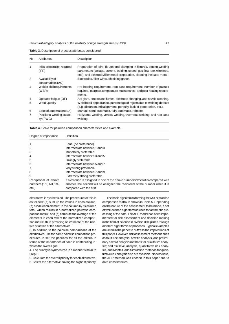
47Structural integrity analysis of the usability of high strength steels (HSS)
Table 3. Description of process attributes considered.
No
1
2
3
45
67
Attributes
Initial preparation required(IPR)
Availability ofconsumables (AC)Welder skill requirements(WSR)
Operator fatigue (OF)Weld Quality
Ease of automation (EA)Positional welding capac-ity (PWC)
Description
Preparation of joint, fit-ups and clamping in fixtures, setting weldingparameters (voltage, current, welding, speed, gas flow rate, wire feed,etc.), and electrode/filler metal preparation, cleaning the base metal.Electrodes, filler wires, shielding gases
Pre-heating requirement, root pass requirement, number of passesrequired, interpass temperature maintenance, and post-heating require-ments.Arc glare, smoke and fumes, electrode changing, and nozzle cleaning.Weld bead appearance, percentage of rejects due to welding defects(e.g. distortion, misalignment, porosity, lack of penetration, etc.).Manual, semi-automatic, fully automatic, roboticsHorizontal welding, vertical welding, overhead welding, and root passwelding.
Table 4. Scale for pairwise comparison characteristics and example.
Degree of importance
123456789Reciprocal of abovenumbers (1/2, 1/3, 1/4,etc.)
Definition
Equal (no preference)Intermediate between 1 and 3Moderately preferableIntermediate between 3 and 5Strongly preferableIntermediate between 5 and 7Very strong preferableIntermediate between 7 and 9Extremely strong preferableIf a criterion is assigned to one of the above numbers when it is compared withanother, the second will be assigned the reciprocal of the number when it iscompared with the first
alternative is synthesized. The procedure for this isas follows: (a) sum up the values in each column,(b) divide each element in the column by its columntotal, which results in a normalized pairwise com-parison matrix, and (c) compute the average of theelements in each row of the normalized compari-son matrix, thus providing an estimate of the rela-tive priorities of the alternatives.3. In addition to the pairwise comparisons of thealternatives, use the same pairwise comparison pro-cedures to set the priorities for all the criteria interms of the importance of each in contributing to-wards the overall goal.4. The priority is synthesized in a manner similar toStep 2.5. Calculate the overall priority for each alternative.6. Select the alternative having the highest priority.
The basic algorithm to forming the M X N pairwisecomparison matrix is shown in Table 5. Dependingon the nature of the assessment to be made, a setof well-defined algorithms is used for arithmetic pro-cessing of the data. The AHP model has been imple-mented for risk assessment and decision makingin the field of science in diverse disciplines throughdifferent algorithmic approaches. Typical examplesare sited in the paper to buttress the implications ofthis paper. However, risk assessment methods suchas fault tree analysis, bow tie analysis, and prelimi-nary hazard analysis methods for qualitative analy-sis; and risk level analysis, quantitative risk analy-sis, and Monte Carlo Simulation methods for quan-titative risk analysis also are available. Nonetheless,the AHP method was chosen in this paper due todata consistencies.

48 E.A. Gyasi and P. Kah
Table 5. Pairwise comparison matrix for AHP computation.
After establishing the M X N matrix, a reciprocalmatrix is formed. This step is preceded by normal-izing the matrix by totaling the numbers in eachcolumn. To check for consistency of original prefer-ence rating, a consistency analysis is made throughconsistency index and ratio calculations [37,38].
M X N matrix
Table 6. Pairwise comparison of attributes. Reprinted with permission from V. Balasubramanian, V. Ravisankar,C. S. Ramachandran and C. Muralidharan // Int J Adv Manuf Technol, Springer-Verlag, London. 40 (2009)887. © 2008 Spri]ger-Verlag Lo]do] Limited.
In the field of welding, several studies have uti-lized AHP for decision-making. Selection of a weld-ing process to fabricate a butt joint of high strengthaluminum alloy of AA 7075 grade using AHP wasinvestigated in [39]. In the work, several activitiesand cost drivers were used as the criteria to mea-sure the alternating factors of GMAW, GTAW andplasma arc welding (PAW). With reference to Table3, the results of the experiment revealed that weldquality was the most important attribute, thus giv-ing rise to GTAW as the process with the higherpriority weight.
In a recent study [40], AHP was used for selec-tion of a welding process for hardfacing on carbonsteels. In the work, a number of carbon steel speci-men were hardfaced with varying heat inputs fromwelding processes such as SMAW, GMAW,GTAW, SAW and plasma transfer arc welding
(PTAW). Percentages of dilution were used as thecriteria to measure the alternating factors. Table 6shows the pairwise comparison matrix for the at-tribute factors. In Table 7, the pairwise comparisonmatrix of the welding processes on initial prepara-tion requirement is illustrated. The tables of thepairwise comparison matrix for the other attributes(AC, WSR, OF, PC, EA, and PWC) are omitted inthis paper. However, Table 8 shows the final com-posite rating of the welding processes.
Based on the quantitative factors (percentage ofdilution), the PTWA process was preferred since itproduced the lowest percentage of dilution level asa result of the low percentage of the base metal inthe deposited weld metal. Moreover, from the quali-tative factors, it was noticed that operator fatiguewas the most important attribute with the highestpriority weight. Based on this result, the welding
Table 7. Pairwise comparison of welding processes on initial preparation requirement. Reprinted withpermission from V. Balasubramanian, V. Ravisankar, C. S. Ramachandran and C. Muralidharan // Int J AdvManuf Technol, Springer-Verlag, London. 40 2009) 887. © 2008 Spri]ger-Verlag Lo]do] Limited.

49Structural integrity analysis of the usability of high strength steels (HSS)
Table 8. Final composite rating of the welding processes. Reprinted with permission from V. Balasubramanian,V. Ravisankar, C. S. Ramachandran and C. Muralidharan // Int J Adv Manuf Technol, Springer-Verlag,London. 40 2009) 887. © 2008 Spri]ger-Verlag Lo]do] Limited.
Fig. 7. On-line process monitoring and failure analysis layout for risk assessment process.
process selected was PTAW, since it had the high-est composite weight of 0.503 with the highest pri-ority weight of 0.3930 as shown in Table 8.
The scientific relevance of the AHP thereforeserves as a step beyond the conventional way ofdetermining structural integrity where destructive andnon-destructive tests are solely performed. In addi-tion, the AHP create new ways for expressing vari-ables and welding parameters when defining andimplementing welding procedure specification. More-over, it create avenues to develop new approacheslike the utilization of on-line process monitoring andfatigue analysis systems to facilitate risk assess-ment process when considering structural integrityin welding.
4. ON-LINE PROCESS MONITORINGAND FATIGUE ANALYSIS
A practical developmental case is the utilization ofmachine-human interface equipment such as sen-sor and camera based systems for on-line processmonitoring, as indicated in the framework and intro-duction part of this paper. Fig. 7 describes on-lineprocess monitoring and failure analysis layout forthe risk assessment process. In on-line processmonitoring, the key aspects are pre-process moni-toring, in-situ monitoring and post-process monitor-ing. Seam tracking, groove volume and groove shapeare observed with pre-process monitoring, and tem-perature, metal vapor, back reflection and metal pool

50 E.A. Gyasi and P. Kah
shape are monitored with in-situ monitoring. Post-process monitoring is used to monitor the shape ofthe weld bead, and to evaluate surface flaws. Fail-ure analysis involving design investigations of weldprofile/geometry, stress data predictions from ther-mal history of microstructural transformations, andfabrication detail assessment rely on feedback in-formation obtained from the on-line process moni-toring system.
The on-line process monitoring and failure analy-sis system with AHP risk assessment process sys-tem enables effective structural integrity analysis ofweldability and service performance as it helps toidentify flaws before, during and after welding. There-fore incorporating the digitalized computational sys-tem with AHP risk assessment process systemwould provide a high degree for quality improvementand assurance when establishing procedures toensuring structural integrity of an HSS structure.
5. DISCUSSION
From the weldability viewpoint, risks associated withwelding of HSS include HAZ softening, cracking,and brittleness in the weld bead. HAZ softening is aresult of microstructural changes that occur whenhigh heat inputs are applied. Heat input is conse-quently a critical factor which significantly affectsthe strength and properties of HSS welded joints.For instance, if heat input is too low, there is a riskof lack of fusion, and on the other hand if the heatinput is too high, the heat affected zone gets toowide, which can cause HAZ softening and brittle-ness in the weld bead [41]. Although such riskslead to ductility, strength, and toughness problems,they also affect the quality of weld joints and bringabout low welding productivity. In addition, risk ofcracking is a factor in the choice of filler materials.This occurrence is usually due to improper weldmetal (base metal plus filler material) dilution. Asheat-input plays a significant role in such phenom-enon thereby causing low toughness in the HAZand the weld metal, care must be taken when se-lecting or choosing matched, under-matched or over-matched filler materials in welding HSS. Productiv-ity wise, this situation leads to consumable wast-age and also lots of repair work due to low qualitywelds which are also prone to fracture toughnessfailure.
Secondly, from the viewpoint of service perfor-mance, fatigue strength of HSS does not increasewith increasing yield strength, but strength proper-ties of the material are associated with load carry-ing capacity. Fatigue strength is consequently re-
duced by means of welding as a result of the soft-ening phenomenon of the HAZ. Risk factors asso-ciated with service performance of a welded HSSinclude weld geometry, material grade and thick-ness, and crack growth. For weld geometry, designand fabrication play a critical role as both variablesare closely dependent on each other. Therefore poordesign leads to wrong fabrication and vice versa.The process of fabrication and welding create levelsof stress on the geometric profile of the weld. Addi-tionally, stress concentration arises as the weldedstructure is subjected to static or dynamic loading,thus reducing fatigue life. Furthermore, the risk ofcrack growth is highly pronounced when there areimperfections in the weldment. For instance, de-fects such as undercut, porosity, etc. create notchesand discontinuities which give rise to further stressconcentrations. In such events, crack initiation,usually located at the weld toe or at the weld root,begins, followed by crack propagation.
In order to alleviate such potential flaws, riskassessment and controls should be performed.Using the AHP model could yield satisfactory re-sults in decision making since qualitative and quan-titative factors can be assessed in detail. Severalcriteria with relative importance could be used asmeasures in the risk assessment process. Theability to lower risk to ensuring sound structural in-tegrity in the process of welding HSS could be high.As part of HSS weldability predictions, on-line weld-ing process monitoring system could be employedfor seam and groove tracking, weld pool shape moni-toring, and weld bead and weld metal surface flawsmonitoring as a measure to identify flaw before, duringand after welding
For service performance of HSS, the design andfabrication aspects must be precise. In addition,despite the limitations of correcting weld flaws withthe on-line process monitoring system, obtainingdigital feedback from the system would help in thecomputation and controllability of welding param-eters to level with fatigue strength and also fatiguelife of the parent metal. Minimization of elastic stressconcentration and decrease of fatigue notch factorbecomes achievable. These procedures when criti-cally examined and practiced would also serve agreat deal to reduce extra costs in HSS welding.
6. CONCLUSIONS
Potential benefits from utilization of HSS for indus-trial applications cannot be under-estimated despitethe material’s drawbacks due to weldi]g effects. Asnew applications are emerging in the metal indus-

51Structural integrity analysis of the usability of high strength steels (HSS)
try, the weldability and service performance of HSSproves to be an intriguing issue which needs to beunderstood from industrial and scientific point ofviews. Therefore, a rigorous risk assessment pro-cess needs to be performed, considering the met-allurgical, physical and mechanical flaws observedin previous studies, when selecting welding pro-cesses and filler material in welding HSS of differ-ent material grade and thickness.
Adapting the AHP system would be an effectiveapproach for evaluating the selection of welding pro-cesses and filler material in HSS welding. The AHPsystem therefore creates a paradigm shift from theconventional method of selecting and assessingwelding processes and filler materials in weldingHSS. Likewise, design and fabrication processesneed to be pre-assessed under welding conditionsto lessen flaws in weld geometry, crack formation,and to prevent fatigue failure in order to ascertainconsiderable fatigue life. This is achievable by em-ploying sensor and camera based systems for on-line welding process monitoring and advanced simu-lation tools for failure analysis during and after de-sign and fabrication phases.
However, the limitations of the on-line weldingprocess monitoring system mean that further re-search is required, for example, on neuro-fuzzy net-work system as an optimization mechanism for iden-tifying, correcting and eliminating potential flaws be-fore, during and after welding. The arguments pre-sented in this paper not only emphasize onweldability and service performance of HSS, but alsoprovides effective new ways of developing justifiablevariables for welding procedure specifications. There-fore the neuro-fuzzy system when developed andincorporated with AHP and on-line welding processmonitoring would create a new trend for ensuringquality and assuring structural integrity in weldingusability of materials for demanding applications.
REFERENCES
[1] M. Pirinen, The Effects of Welding Heat inputon the Usability of High Strength Steels inWelded Structures (Acta Universitatis,Lappeenrantaensis 514, Finland, 2013).
[2] V. Bertram and T. Lamb, Ship Design andConstruction, Volume 1-2 (Society of NavalArchitects and Marine Engineers - SNAME,Jersey City, 2003-2004).
[3] T. Rantalainen, Simulation of Structural StressHistory Based on Dynamic Analysis (ActaUniversitatis Lappeenrantaensis 494, Finland,2012).
[4] J. Billingham and J.V. Sharp, Review of thePerformance of High Strength Steels usedOffshore (Research Report 105, CranfieldUniversity School of Industrial andManufacturing Science, 2003).
[5] W. Wang and S. Liu // Welding Journal 81(2002) 132.
[6] M. Zeman // Welding International 23 (2009)73.
[7] P. Dainelli and F. Maltrud, Etudes EtRecherche (Institut de Soudure, France,2012).
[8] Hot Rolled Steel Plates, Sheets and Coils(Ruukki Metals, Processing of Materials,Helsinki, 2007).
[9] Quenched and Tempered Steels (TechnicalNote 15, Welding Technology Institute ofAustralia, Milsons Point, 1999).
[10] F. Ade // Welding Journal 70 (1991) 53.[11] P. K. Ghosh, P. C. Gupta, R. Avtar and B. K.
Jha // ISIJ International Journal 30 (1990)233.
[12] M. Xia, E. Biro, Z. Tian and Y. N. Zhou // ISIJInternational Journal 48 (2008) 809.
[13] K. Hakansson, Weld Metal Properties forExtra High Strength Steels (The RoyalInstitute of Technology, KTH, Stockholm,2002).
[14] Quenched and Tempered Steels (TechnicalNote 15, Welding Technology Institute ofAustralia, Milsons Point, 1985).
[15] G. H. Ryder, Fundamentals of WeldingMetallurgy (Jaico Publishing House, Bombay,1994).
[16] H. S. Wang // Materials Transactions 46(2005) 593.
[17] Welding Hand Book (American WeldingSociety, Miami, 1981).
[18] T. Terasaki and T. G. Gooch // ISIJInternational 35 (1995) 1272.
[19] P. Kah, M. Pirinen, R. Suoranta andJ. Martikainen // Advanced MaterialsResearch 849 (2014) 357.
[20] M. J. Cieslak, In: Cracking PhenomenaAssociated with Welding: ASM InternationalHandbook (ASM International, MaterialsPark, 1997), p. 71.
[21] B. A. Graville, In: Welding of HSLA (Micro-alloyed) Structural Steels: American Societyfor Metals (Rome, Italy, 1976), p. 85.
[22] M. Toyosada, In: Proceedings of the TwelfthInternational Offshore and Polar EngineeringConference (Kitakyushu, Japan, 2002),p. 365.

52 E.A. Gyasi and P. Kah
[23] S. Imai, In: Proceedings of the TwelfthInternational Offshore and Polar EngineeringConference (Kitakyushu, Japan, 2002),p. 392.
[24] B. Boardman, In: ASM Handbook: Propertiesand Selection: Irons, Steels, and High-Performance Alloys, ed. by AWS committee(ASW International, Ohio, 1990), p.673.
[25] J. Hicks, Welded Design – Theory andPractice (Woodhead Publishing, England,2001).
[26] K. Weman, Welding Processes Handbook(Woodhead Publishing, England, 2012).
[27] Y. Bai and Q. Bai, Subsea Pipelines andRiser (Elsevier, Oxford, 2005).
[28] M. P. A. Jesus, R. Matos, F. C. Bruno,C. Rebelo, L. S. Silva and M. Veljkovi //Journal of Construction Steel Researc 79(2012) 140.
[29] C. Miki, K. Homma and T. Tominaga //Journal of Construction Steel Research 58(2002) 3.
[30] J. D. M. Costa, J. A. M. Ferreira and L. P. M.Abreu // Procedia Engineering 2 (2010) 697.
[31] S. Beretta, A. Bernasconi and M. Carboni //International Journal of Fatigue 3 (2009) 102.
[32] W. Meng, Z. Li, J. Huang, Y. Wu andS. Katayama // ASM International 23 (2013)541.
[33] G. B. Marquis and Z. Barsoum // ProcediaEngineering 66 (2013) 98.
[34] C. H. Yildirim and G. B. Marquis //International Journal of Fatigue 44 (2012)168.
[35] C. H. Yildirim, G. B. Marquis and Z. Barsoum// International Journal of Fatigue 52 (2013)57.
[36] A. A. Bhatti, Z. Barsoum, V. van der Mee,A. Kromm and T. Kannengiesser // ProcediaEngineering 66 (2013) 192.
[37] T. L. Saaty, Analytical Hierarchy Process(McGraw-Hill, New York, 1980).
[38] T. S. Shores, In: Applied Linear Algebra andMatrix Analysis, ed. by S. Axler and K.ARibet (Springer Science and BusinessMedia, LLC, New York, 2007), p. 24.
[39] V. Ravisankar, V. Balasubramanian andC. Muralidharan // Materials and Design 27(2006) 373.
[40] V. Balasubramanian, V. Ravisankar, C. S.Ramachandran and C. Muralidharan // Int JAdv Manuf Technol 40 (2009) 887.
[41] R. Raunch, S. Kapl, G. Posch andK. Radlmayr // BHM. 157 (2012) 102.

Publication II
Gyasi, E.A., Kah, P., Wu, H. and Kesse, M.A.
Modelling of an artificial intelligence system to predict structural integrity in
robotic GMAW of UHSS fillet welded joints
Reprinted with permission from
International Journal of Advanced Manufacturing Technology
Vol. 93, pp. 1139-1155, 2017
© 2017, Springer


ORIGINAL ARTICLE
Modeling of an artificial intelligence system to predict structuralintegrity in robotic GMAW of UHSS fillet welded joints
Emmanuel Afrane Gyasi1 & Paul Kah1& Huapeng Wu1
& Martin Appiah Kesse1
Received: 27 August 2016 /Accepted: 10 May 2017 /Published online: 7 June 2017# Springer-Verlag London 2017
Abstract The use of welded lightweight steels in structuralapplications is increasing due to the greater design possibili-ties offered by such materials and the lower costs compared toconventional steels. Ultra-high-strength steels (UHSS) havingtensile strength of up to 1700 MPa with a high strength-to-weight ratio offer a unique combination of qualities for diverseindustrial applications. For productivity and quality reasons,gas metal arc welding (GMAW) is usually utilized for weldingof UHSS. However, for full penetration fillet welded joints,the need for high heat input to gain acceptable weld penetra-tion is problematic when welding UHSS. This is due to UHSSsensitivity to heat input and possible heat-affected zone(HAZ) softening. In this paper, an attempt is made, on thebasis of analysis of experimental reviews, to identify and de-fine relationships between nonlinear weldability factors to en-able creation of an artificial intelligence model to predict fullpenetration in robotic GMAW fillet welded joints of UHSSS960QC. Welding variables and parameters associated withGMAW are first evaluated by reviewing scientific literature.The possibility of employing an artificial neural network(ANN) to predict full penetration fillet weld characteristics isthen examined. It is noted that nonlinear variables associatedwith the GMAW process, such as heat input, contact tip towork distance (CTWD), and torch angle, and their relatedparameters, which pose weldability challenges, can bemodeled by applying artificial intelligence systems.Ensuring full penetration in fillet welded joints of UHSS using
artificial intelligence is thus feasible. Further, an optimizedcontrol system could potentially be developed by incorporat-ing adaptive robotic GMAW with an artificial intelligence-based system to guarantee sound structural integrity that con-forms to EN ISO 5817. The paper increases awareness ofwelding aspects of UHSS S960QC and presents an approachfor overcoming existing limits to GMAW via adaptive roboticwelding and artificial intelligence systems.
Keywords Ultra-high-strength steel (UHSS) . RoboticGMAW .Artificial intelligence .Structural integrity .Artificialneural network . Full penetration .Weld quality
1 Introduction
Nowadays, manufacturing industries are increasinglyemploying lightweight steels of high tensile strength inwelded structural applications as a response to the need toreduce structural weight and attain cost reductions in weldingmanufacturing and production. These needs stem from de-mands for increased energy efficiency, which has become crit-ical from the environmental point of view. Ultra-high-strengthsteel (UHSS) is one material choice for lightweightmanufacturing. UHSS has superior strength-to-weight ratioand excellent physical, mechanical, and low-temperatureproperties, which enable lower fuel consumption and lowercarbon emissions [1–4] than when using conventional steels.Industries that produce and operate mobile structures such asoffshore platforms, floating production, storage, andoffloading (FPSO) units, heavy-duty vehicles for mining orlifting purposes, and alternative energy industries operating inthe fields of solar power, wind power, and liquefied naturalgas (LNG) production stand to benefit from increased use ofUHSS.
* Emmanuel Afrane [email protected]; [email protected]
1 School of Energy Systems, Mechanical Engineering Department,Laboratory of Welding Technology, Lappeenranta University ofTechnology, P.O. Box 20, 53851 Lappeenranta, Finland
Int J Adv Manuf Technol (2017) 93:1139–1155DOI 10.1007/s00170-017-0554-0

Amajor challenge facingmanufacturing industries is to guar-antee that full penetration is achieved in fillet welded joints ofstructural applications. Increased heat input is generally utilizedto ensure acceptable full weld penetration in fillet joints.
As a result of the alloying elements and production processused in its manufacture, UHSS possesses a dual-phase micro-structure consisting of bainite and martensite [1]. Its micro-structure, similar to advanced high-strength steels (AHSS), issensitive to high heat input, and exposure to elevated temper-ature can change its mechanical properties. More critical ef-fects of heat input are heat-affected zone (HAZ) softening andan increased propensity to fatigue failure, which affect thetoughness and strength of welded joints of UHSS [2, 3].
For productivity and quality reasons, fusion welding pro-cesses, especially gas metal arc welding (GMAW), have beenfavored for joining lightweight high tensile strength steels. Anumber of studies have been presented where GMAW hasbeen employed for welding of UHSS S960QC [1–3].Successful implementation of robotic GMAW in UHSSwelding would have a significant effect on the profitabilityof manufacturing industry, where repeatability, precision, cost,time, and quality are key drivers in manufacturing and pro-duction. However, utilizing robotic GMAW in an uncon-trolled manner poses weldability challenges for the structuralintegrity of UHSS fillet welded joints. The outcome of theGMAW process is dependent on a number of nonlinear vari-ables, such as heat input, contact tip to work distance(CTWD), and torch angle, and their related parameters, e.g.,arc current, arc voltage, welding speed, gas flow rate, arcefficiency, electrode stick out, wire feed speed, electrode di-ameter, torch position, and torch travel angle.
Development in artificial intelligent system for roboticwelding shows that adaptive features such as sophisticallysensory, monitoring, and control systems could be incorporat-ed in the entire robotic artificial intelligent welding system tohelp the robot to adjust to its operating environment to enablemonitoring, detection, measurement, inspection, and record-ing welding process parameters, and other features such asjoint geometry and weld pool geometry. A typical examplelike infrared thermography-based sensors could be used inadaptive robotic artificial intelligent system to measure ther-mal profiles during welding to check susceptibility to heatinputs and temperature variations to assure weld integrity.However, for the robot to be capable to self-adjust to its func-tions and operations, artificial intelligent systems such as arti-ficial neural network (ANN), fuzzy logic system, neural-fuzzynetwork (NFN), adaptive neuro-fuzzy inference system(ANFIS), genetic algorithm (GA), or swam particle optimiza-tion (SPO) need to be used as a data modeling tool. Theseartificial intelligent systems not only adapt, aid prediction ofdesired outcomes, and operate real time but are also capable tolearn new input and output relationships and previously un-known situations and environments.
Therefore, development of a system able to account for andcontrol the nonlinear factors associated with GMAW wouldalleviate weldability problems and guarantee sound structuralintegrity and full penetration in fillet welded joints of UHSS,enabling the joints to conform to the EN ISO 5817 standard,and would be a valuable scientific contribution to weldingscience, and manufacturing and production industries.
In this paper, an attempt is made, on the basis of analysis ofexperimental reviews, to identify and define relationships be-tween nonlinear weldability factors to enable creation of anartificial intelligence (AI) model to predict full penetration inrobotic GMAW fillet welded joints of UHSS S960QC.Figure 1 illustrates the concept of modeling an AI system forrobotic welding of UHSS. It is assumed that all required inputsand the relationship between the inputs and the correspondingoutput requirements must be identified and considered. In ad-dition, it is anticipated that the AI system should be able topredict desirable weld characteristics, such as weld bead pen-etration depth and weld geometry, based on the input data andexpected outcomes.
A further requirement for the system is the ability to pre-dict, during the welding process, possible weld flaws or errorsin data modeling, as outputs, on receiving input requirementslike welding parameters. In situations where undesirable out-comes and defects are likely to occur, the intelligent systemshould be able to capture, control, and correct the errors. Thisimportant adaptive function requires an optimized control sys-tem, whose discussion is beyond the scope of this work.
2 Material and welding considerations for weldingof UHSS S960QC
Experimental studies have shown that welding of UHSS ischallenging due to several nonlinear factors that affectweldability [1]. For example, weldability problems can occuras a result of inappropriate heat input and choice of fillermaterials [2], and problems can arise from fatigue effects re-lated to weld geometry/profiles [3]. Figure 2 presents and
Fig. 1 Schematic diagram ofmodeling of an artificial intelligence systemfor a robotic GMAW process
1140 Int J Adv Manuf Technol (2017) 93:1139–1155

summarizes information regarding standard requirements,material properties, and welding of UHSS S960QC. The sche-matic data representation does not provide a complete weldingprocedure specification (WPS) since items such as weldingposition, type of polarity, size of filler material, need for pre-heating or post-heating, and procedure sequence are missing.Such information is case-specific to the particular structurebeing welded, and it thus cannot be generalized but must bevalidated for the specific welding procedure. Nevertheless, theschematic data serves as relevant technical information whenconsidering UHSS S960QC for experimental study.
For fillet welded joints, higher levels of structural integritycannot be guaranteed due to susceptibility to a lack of fullpenetration [5]. In most cases, extra material preparations suchas beveling have to be done, especially on the upright memberof the fillet joint profile. This requirement increases materialpreparation costs and such pre-welding preparation cannot beutilized in many applications. Tables 1 and 2 show qualitylevels and critical imperfections in fillet welded joints accord-ing to EN ISO 5817. The quality levels are designated bysymbols B, C, and D, where B corresponds to the highestrequirement on the finished weld. The load types evaluated
Fig. 2 Schematic representation of UHSS S960QC material data and robotic GMAW process fillet joint
Int J Adv Manuf Technol (2017) 93:1139–1155 1141

in definition of these quality levels include static load, thermalload, corrosion load, and pressure load [6].
Tables 1 and 2 serve as a guide for the objective of creatinganAImodel to predict full penetration in robotic GMAW filletwelded joints of UHSS S960QC. Surface imperfections suchas excessive convexity, incorrect weld toe, excessive asym-metry of the fillet weld, insufficient throat thickness, and ex-cessive throat thickness must fall within the acceptable qualitylevel range in accordance with the EN ISO 5817 standard formaterial thickness greater than or equal to 0, 5, to 3 mm.Similarly, in Table 2, the quality level range in accordancewith EN ISO 5817 standard for material thickness greater thanor equal to 0, 5, to 3 mm must be observed for internal, jointgeometry, and multi-imperfections.
2.1 Case study 1
Hemmilä et al. [1] investigated the weldability of Optim960QC, which is the same as UHSS S960QC, for 3- and 6-mm-thick plates. In order to establish a basis for comparisonof the effects of heat input, 3-mm-thick plates were preparedfor laser welding and MAG welding, and 6-mm-thick plateswere prepared for hybrid laser welding (CO2 laser and MAGwelding using shielding gas: 50% He + 45% Ar + 5% CO2)and MAG welding using shielding gas: 80% Ar + 20% CO2.Experimental data from the study is shown in Table 3. TheMAG welding equipment employed was ESAB LAH 630from Ruukki Productions, nowaday a division of SSAB.The laser and laser-hybrid welding equipment used were,
Table 1 Surface imperfections in fillet welded joints [6]
1142 Int J Adv Manuf Technol (2017) 93:1139–1155

respectively, a Rofin-Sinar 6000 and ESAB ARISTO 2000welding system.
In the laser-hybrid welding, the joints were tack weldedusing the MAG process and the distance between tacks wasapproximately 100 mm. In the other MAG welding, the 6 mmplate was milled and a V-groove cut. The welding was carriedout without preheating using interpass temperatures of 25 °Cand arc energies of 0.5 and 0.8 kJ/mm.
Non-destructive visual andX-ray examination conforming toEN ISO 15614-1 showed that class B (stringent) was generallyachieved in theMAG-welded joints, but classCdominated in thelaserand laser-hybridwelded joints.The lowerqualityclassof thelaser and laser-basedmethodswas due to higher porosity, incom-plete filling of grooves and roots, and local lack of fusion.Figures 3 and 4 showVickers hardness profiles across thewelds.
It was concluded that the HAZ showed a significant drop inhardnessbelowthatof thebaseplate in theMAGweldingof the3-
mmplate, as can be seen inFig. 3. The narrow, shallow softHAZin the autogenous laser weld of the 3-mm plate did not lower thetensile strengthof the joint compared to that of thebaseplate.Theuseof laseror laser-hybridweldingcould thereforehelp to reducethe width and depth of the HAZ softened zone.
Weld metal was even-matching in the case of the laser-basedmethods, but slightly under-matching in the MAG weld of the 3-mmplate.However,inboththe3-and6-mmplates,theMAGweldsdemonstratedcross-weld tensile strength thatwas lower than thatofthebaseplate.Foraconstantheat input(0.5kJ/mm),thereductionintensile strength increased as the plate thickness decreased from6 to3mm, as can be seen by comparison of Figs. 3 and 4.
A similar effect was obtained when increasing the arc en-ergy in the case of the 6-mm-thick MAG-welded butt joints:higher arc energy (0.8 kJ/mm) produced greater under-matching. Cross-weld tensile strength decreased as arc energyand cooling time increased.
Table 2 Surface imperfections in fillet welded joints [6]
Int J Adv Manuf Technol (2017) 93:1139–1155 1143
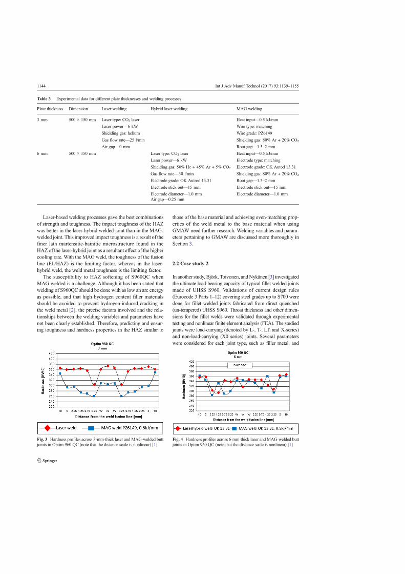
Laser-based welding processes gave the best combinationsof strength and toughness. The impact toughness of the HAZwas better in the laser-hybrid welded joint than in the MAG-welded joint. This improved impact toughness is a result of thefiner lath martensitic-bainitic microstructure found in theHAZ of the laser-hybrid joint as a resultant effect of the highercooling rate. With the MAG weld, the toughness of the fusionline (FL/HAZ) is the limiting factor, whereas in the laser-hybrid weld, the weld metal toughness is the limiting factor.
The susceptibility to HAZ softening of S960QC whenMAG welded is a challenge. Although it has been stated thatwelding of S960QC should be done with as low an arc energyas possible, and that high hydrogen content filler materialsshould be avoided to prevent hydrogen-induced cracking inthe weld metal [2], the precise factors involved and the rela-tionships between the welding variables and parameters havenot been clearly established. Therefore, predicting and ensur-ing toughness and hardness properties in the HAZ similar to
those of the base material and achieving even-matching prop-erties of the weld metal to the base material when usingGMAW need further research. Welding variables and param-eters pertaining to GMAW are discussed more thoroughly inSection 3.
2.2 Case study 2
In another study, Björk, Toivonen, andNykänen [3] investigatedthe ultimate load-bearing capacity of typical fillet welded jointsmade of UHSS S960. Validations of current design rules(Eurocode 3 Parts 1–12) covering steel grades up to S700 weredone for fillet welded joints fabricated from direct quenched(un-tempered) UHSS S960. Throat thickness and other dimen-sions for the fillet welds were validated through experimentaltesting and nonlinear finite element analysis (FEA). The studiedjoints were load-carrying (denoted by L-, T-, LT, and X-series)and non-load-carrying (X0 series) joints. Several parameterswere considered for each joint type, such as filler metal, and
Table 3 Experimental data for different plate thicknesses and welding processes
Plate thickness Dimension Laser welding Hybrid laser welding MAG welding
3 mm 500 × 150 mm Laser type: CO2 laser Heat input—0.5 kJ/mm
Laser power—6 kW Wire type: matching
Shielding gas: helium Wire grade: PZ6149
Gas flow rate—25 l/min Shielding gas: 80% Ar + 20% CO2
Air gap—0 mm Root gap—1.5–2 mm
6 mm 500 × 150 mm Laser type: CO2 laser Heat input—0.5 kJ/mm
Laser power—6 kW Electrode type: matching
Shielding gas: 50% He + 45% Ar + 5% CO2 Electrode grade: OK Autod 13.31
Gas flow rate—30 l/min Shielding gas: 80% Ar + 20% CO2
Electrode grade: OK Autrod 13.31 Root gap—1.5–2 mm
Electrode stick out—15 mm Electrode stick out—15 mm
Electrode diameter—1.0 mm Electrode diameter—1.0 mmAir gap—0.25 mm
Fig. 3 Hardness profiles across 3-mm-thick laser and MAG-welded buttjoints in Optim 960 QC (note that the distance scale is nonlinear) [1]
Fig. 4 Hardness profiles across 6-mm-thick laser and MAG-welded buttjoints in Optim 960 QC (note that the distance scale is nonlinear) [1]
1144 Int J Adv Manuf Technol (2017) 93:1139–1155

length and throat thickness of the welds. A fully mechanizedGMAWprocess (MAG)was used for joining the plates of 8mmthicknesses. The test results showed that ductile rupture oc-curred in all the joints when tested at room temperature.Additionally, the optimal cooling rate was difficult to reach;low heat input increased the risk of incomplete fusion. In theX0 series, however, the failure and capacity of the non-load-carrying joints seemed to depend on the heat input due towelding. When heat input was low, the softening was local,and it had no effect on the load-bearing capacity of the joint,and the failure occurred outside the joint (typically at an angle of30°) as shown in Fig. 5. When heat input was increased, thesoftened width/plate thickness ratio increased and the criticalratio, experimentally about 0.2, was exceeded. Consequently,the failures occurred in the HAZ next to the weld.
It can be seen from Fig. 5 that heat input of 0.61 kJ/mmgenerated low throat size of 4.5 mm and smaller HAZ than withheat inputs of 0.77 and 0.94 kJ/mm. Based on measured ulti-mate strength of the base material, strain hardening seems not tocompensate the softening effect. Therefore, in addition to ensur-ing that the load-carrying capacity of the fillet weld agrees withthe design rules (Eurocode 3 Parts 1–12), heat input must beconsidered due to the softening effect on the HAZ. S960 toler-ates very high cooling rates and strength properties for thewelded joint are reached if the t8/5-time is less than 10 s.Consequently, the strength properties of the HAZ will drop bymore than 10% of the strength of the base material when theoptimal cooling rate is not reached. In addition, for matchedfiller materials, the weakest strength appears in the HAZ, butfor under-matched electrodes, the weakest strength appears intheweld itself. However, utilizing under-matched filler materialscan improve the deformation capacity of fillet welds if criticalheat input limits are observed.
3 Robotic GMAW process parameters and variables
Development in industrial robotics has had a profound effecton modern welding, and industrial welding geared towards
high quality and high productivity is nowadays often carriedout using state-of-the-art robots. The GMAW process is mostoften used as the joining technique for robotic welding, main-ly because of its flexibility and adaptability. Industrial GMAWis commonly a semi-automatic welding process since it uti-lizes an inert or active gas to shield a consumable and contin-uously fed filler material.
The GMAWprocess is defined by the shielding gases used,that is, metal inert gases in MIG welding, which are argon andhelium gases, and metal-active gases in MAG welding, gen-erally argon and carbon dioxide.
A large number of welding experiments have been con-ducted with the GMAWprocess. Table 4 presents key weldingvariables and parameters and indicates studies in which theywere investigated. The defining welding parameters are heatinput, contact tip to work distance, and torch angle. The stud-ies listed in the right-hand column of Table 4 are utilized forthe purposes of this work. In the studies, some welding pa-rameters were assumed to be constants, for example arclength. The listed welding variables and parameters affectthe weld geometry characteristics and properties of the weldand are considered in more detail in the following sections.
3.1 Heat input
Heat input influences the way molten filler material is trans-ferred to the workpiece, arc stability, generation of spatter,weld bead profile formation, and weld quality. Most impor-tantly, the terminology heat input is used because only part ofthe welding energy as established from these welding param-eters enters the workpiece [17]. The expression for heat inputis presented in Eq. (1) [18].
Heat input kJ=mmð Þ
¼ Arc voltage Eð Þ � Arc current Ið Þ � 60� Arc efficiency ηð ÞWelding speed Vð Þ � 1000
ð1Þ
As can be seen from Eq. (1), the relationship between cur-rent and voltage greatly influences the heat input value. Arccharacteristics under conditions of stable arc and uniform arclength give synergetic control of voltage and current. Ohm’slaw therefore does not satisfy the current and voltage relation-ship in welding, where increase in current results in voltageincrease [19].
In GMAW, it has been observed that the arc mode, and thusthe weld quality, is greatly influenced by the arc current [20]as a heat input parameter. The depth of penetration is signifi-cantly influenced by the arc current; depth of penetration in-creases with increase in current [21]. However, increased jointpenetration also increases the possibility of burn-through andsolidification cracking. Experiments have shown that a higherFig. 5 Failure modes in non-load-carrying joints of UHSS S960 [3]
Int J Adv Manuf Technol (2017) 93:1139–1155 1145

current leads to a higher electromagnetic force, which causesthe droplet to detach from the electrode and transfer to theweld pool. Furthermore, with a higher current, the size ofthe molten droplet is smaller and there is a higher dropletfrequency.
Arc penetration depends also on electrode polarity.The penetration characteristic of GMAW with directcurrent electrode positive (DCEP), i.e., reverse polarity,and direct current electrode negative (DCEN), i.e.,straight polarity, are depicted in Fig. 6. DCEP is mostlyutilized because it produces good weld bead geometryand depth of weld penetration, and generates only lowlevels of spatter [20].
The current for a given GMAW solid or metal-coredelectrode will reach a maximum density level and oncethis level is attained, no additional current can be car-ried by the electrode; thus, the electrode has reached itsmaximum current density [22]. Notably for a given heatsource, the extent to which energy is absorbed by theworkpiece depends on the rate of heat absorption of thematerial, the type of heat source, and the parameters ofthe welding process (voltage, current, and weldingspeed) [17]. Thus, from the arc efficiency expressionshown in Eq. (2), it is imperative to determine the rate
of heat absorption of the material when considering therelation between the current and voltage values.
η ¼ 1−1−nð Þqpþmqw
EIð2Þ
where
η arc efficiency, expressed as a fraction, %n proportion of the energy radiated and convected from the
arc column per unit of time and transferred to theworkpiece, expressed as a fraction, %
qp energy radiated and convected from the arc column perunit of time, Btu/min (cal/s)
m proportion of heat radiated away from the workpiece,expressed as a fraction, %
qw rate of heat absorbed by the workpiece, Btu/min (cal/s)E voltage, VI welding current, A
Experiments reveal that arc efficiency is higher for con-sumable electrode processes than for non-consumable elec-trode processes due to heat losses from the arc to the surround-ings.With consumable electrodes, heat loss from the electrodecan often be ignored as the energy transferred to the electrode
Table 4 GMAW weldingvariables and parameters used inreviewed experiments
Welding variables Welding parameters References
Heat input Arc current [7–15]
Arc voltage [7–16]
Welding speed [7–16]
Gas flow rate [7, 8, 11, 13, 15, 16]
Contact tip to work distance (CTWD) Electrode extension [11, 15]
Arc length [7–15]
Wire feed speed [11, 15]
Wire diameter [7, 8, 10, 11, 13–16]
Torch angle Torch position [8]
Torch travel angle [11]
Fig. 6 Arc penetrationcharacteristics of GMAW with aDCEN and b DCEP electrodepolarity
1146 Int J Adv Manuf Technol (2017) 93:1139–1155

is eventually absorbed by the workpiece. Arc efficiency inGMAW falls within the range 66–85% [17, 23]. It has beenobserved that gas tungsten arc welding (GTAW) loses sub-stantially more heat from the arc to the surrounding environ-ment than GMAW, shielded metal arc welding (SMAW), andsubmerged arc welding (SAW). It must be noted that thisgeneralization can result in supplying too high or too low heatinput since specifications of material grade and strength arenot given [17]. This observation, though, gives an indicationof how to determine the rate of heat absorption of a materialwhen establishing welding heat inputs, as in the case ofUHSS. It should however be noted that the higher the heatconductivity of a material, the lower the penetration [21].
FortheGMAWprocess,arcvoltageisproportionaltoarclength.Welding with a high voltage produces a wide and flat weld beadwith possible undercuts, and welding with too low voltage pro-duces a low-quality weld bead with high concave reinforcement[24,25]anddecreaseddepthofpenetration[21].Arcvoltagecanbecontrolled by altering the arc length [26]. Too small arc lengthmaygive rise to poor penetration if the arc power is very low [21].
Gas flow rate and welding speed play major roles in deter-mining heat input. The electric arc is stabilized by the arcplasma as a result of ionization of the shielding gas. In addi-tion, the mode of metal transfer from the consumable elec-trode is determined by the arc type and also depends on thegas flow rate. In GMAW, binary shielding gas blends (argon +helium, argon + CO2, or argon + oxygen) or ternary shieldinggas blends (helium + argon + CO2, or argon + CO2 + oxygen)are mostly utilized [22, 27]. Table 5 shows GMAWarc types,descriptions, and material application.
The extent of convective loss depends on the nature of theshielding gas, its flow rate, and its configuration system [17]. Itmust be noted that the percentage mixture of CO2 in both binaryand ternary blends has an effect on heat input, and defining therelationship between CO2 percentage and control of current andvoltage values is imperative. Extensive research on arc types hasshown that in many applications, greater benefit accrues fromspray and pulsed arcs than short and globular arc modes [27].Moreover, enhanced arc processes such as controlled short arc,heavy deposition rate arc, and controlled spray arc offer signif-icant improvements in efficiency and usability [27].
Welding speed contributes to determining the cooling rateduring and after welding. The variation of temperature withtime as a function of the cooling rate, often referred to as thethermal cycle, affects microstructures, residual stresses, andthe extent of distortions in weldments. On the surface of theweld pool, the temperature distribution affects the loss ofalloying elements by evaporation as well as absorption anddesorption of hydrogen and other gases. The chemical com-position of the weldment is affected correspondingly.
The cooling rate of a weldment is a function of the rate ofenergy dissipation. Fast welding speed generates fast coolingand vice versa. As weld penetration increases with decreasing T
able5
GMAW
arcdescriptions
andmaterialapplications
Type
ofarc
Shielding
gas
Metaltransfer
Materialapplication
Materialthickness
Shortarc
100%
CO2or
amixture
of75–80%
argon,
plus
25–20%
CO2
Short-circuitin
gFerrous
0.5–2.6mm
Globulararc
100%
CO2,and
argon/CO2blends
Globular
Ferrous
3mm
andbeyond
Axialspay
arc
Argon
+1–5%
oxygen
orargon+CO2,
where
theCO2levelsare18%
orless
Axialspray
Ferrousandnon-ferrous
5mm
andabove
Pulsesprayarc
Argon
+18%
CO2
Pulsespray
Ferrous,non-ferrous,anddissim
ilar
0.3mm
andbeyond
Controlledshortcircuiting
arc
Argon
andCO2based
Short-circuiting
Ferrous,non-ferrous,anddissim
ilar
0.3mm
andbeyond
Controlledglobular
arc
Argon
andCO2based
Globularwith
shortarc
length
(buriedarc)
Ferrous
3mm
andbeyond
Controlledsprayarc
Argon
andCO2based
Spray
Ferrous,non-ferrous,anddissim
ilar
1.5mm
andabove
High-power
arc
Argon
andCO2based
Stream
androtatin
gFerrous,non-ferrous,anddissim
ilar
3mm
andbeyond
Int J Adv Manuf Technol (2017) 93:1139–1155 1147
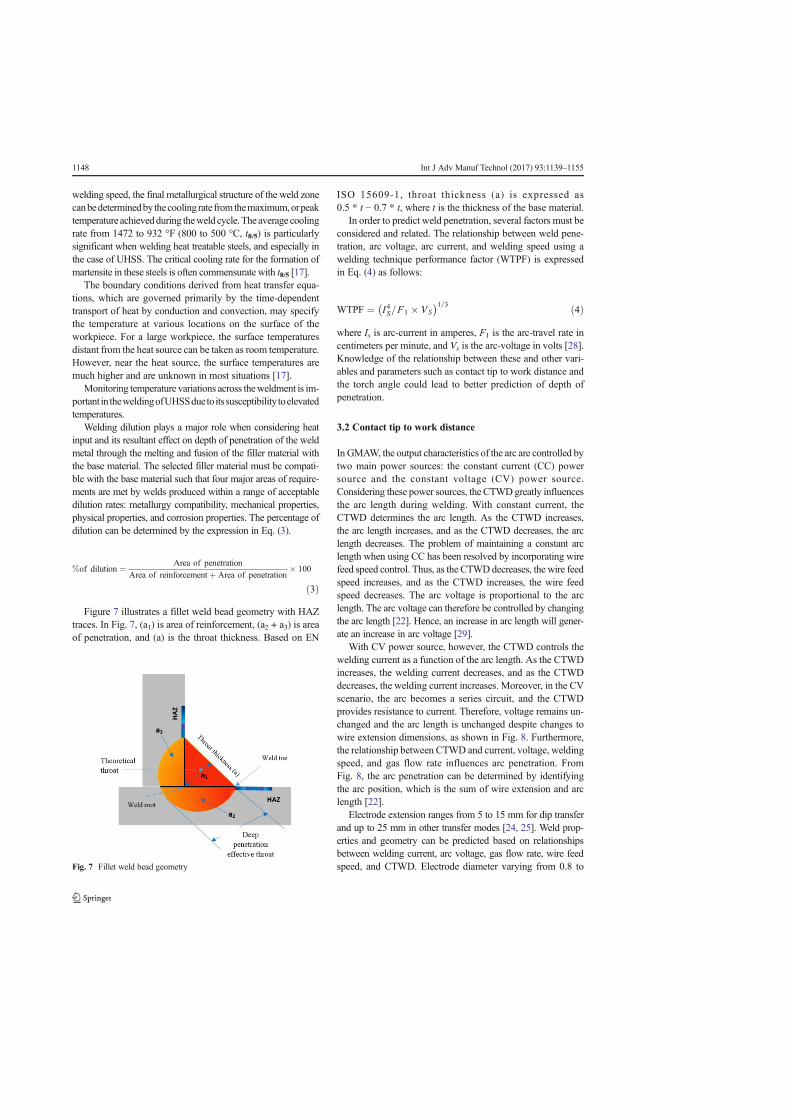
welding speed, the final metallurgical structure of the weld zonecanbedeterminedby thecooling rate fromthemaximum,orpeaktemperature achievedduring theweld cycle.Theaverage coolingrate from 1472 to 932 °F (800 to 500 °C, t8/5) is particularlysignificant when welding heat treatable steels, and especially inthe case of UHSS. The critical cooling rate for the formation ofmartensite in these steels is often commensurate with t8/5 [17].
The boundary conditions derived from heat transfer equa-tions, which are governed primarily by the time-dependenttransport of heat by conduction and convection, may specifythe temperature at various locations on the surface of theworkpiece. For a large workpiece, the surface temperaturesdistant from the heat source can be taken as room temperature.However, near the heat source, the surface temperatures aremuch higher and are unknown in most situations [17].
Monitoring temperature variations across theweldment is im-portant in theweldingofUHSSduetoitssusceptibility toelevatedtemperatures.
Welding dilution plays a major role when considering heatinput and its resultant effect on depth of penetration of the weldmetal through the melting and fusion of the filler material withthe base material. The selected filler material must be compati-ble with the base material such that four major areas of require-ments are met by welds produced within a range of acceptabledilution rates: metallurgy compatibility, mechanical properties,physical properties, and corrosion properties. The percentage ofdilution can be determined by the expression in Eq. (3).
%of dilution ¼ Area of penetration
Area of reinforcementþ Area of penetration� 100
ð3Þ
Figure 7 illustrates a fillet weld bead geometry with HAZtraces. In Fig. 7, (a1) is area of reinforcement, (a2 + a3) is areaof penetration, and (a) is the throat thickness. Based on EN
ISO 15609-1, throat thickness (a) is expressed as0.5 * t − 0.7 * t, where t is the thickness of the base material.
In order to predict weld penetration, several factors must beconsidered and related. The relationship between weld pene-tration, arc voltage, arc current, and welding speed using awelding technique performance factor (WTPF) is expressedin Eq. (4) as follows:
WTPF ¼ I4S=F1 � VS� �1=3 ð4Þ
where Is is arc-current in amperes, F1 is the arc-travel rate incentimeters per minute, and Vs is the arc-voltage in volts [28].Knowledge of the relationship between these and other vari-ables and parameters such as contact tip to work distance andthe torch angle could lead to better prediction of depth ofpenetration.
3.2 Contact tip to work distance
In GMAW, the output characteristics of the arc are controlled bytwo main power sources: the constant current (CC) powersource and the constant voltage (CV) power source.Considering these power sources, the CTWDgreatly influencesthe arc length during welding. With constant current, theCTWD determines the arc length. As the CTWD increases,the arc length increases, and as the CTWD decreases, the arclength decreases. The problem of maintaining a constant arclength when using CC has been resolved by incorporating wirefeed speed control. Thus, as the CTWDdecreases, the wire feedspeed increases, and as the CTWD increases, the wire feedspeed decreases. The arc voltage is proportional to the arclength. The arc voltage can therefore be controlled by changingthe arc length [22]. Hence, an increase in arc length will gener-ate an increase in arc voltage [29].
With CV power source, however, the CTWD controls thewelding current as a function of the arc length. As the CTWDincreases, the welding current decreases, and as the CTWDdecreases, the welding current increases. Moreover, in the CVscenario, the arc becomes a series circuit, and the CTWDprovides resistance to current. Therefore, voltage remains un-changed and the arc length is unchanged despite changes towire extension dimensions, as shown in Fig. 8. Furthermore,the relationship between CTWD and current, voltage, weldingspeed, and gas flow rate influences arc penetration. FromFig. 8, the arc penetration can be determined by identifyingthe arc position, which is the sum of wire extension and arclength [22].
Electrode extension ranges from 5 to 15 mm for dip transferand up to 25 mm in other transfer modes [24, 25]. Weld prop-erties and geometry can be predicted based on relationshipsbetween welding current, arc voltage, gas flow rate, wire feedspeed, and CTWD. Electrode diameter varying from 0.8 toFig. 7 Fillet weld bead geometry
1148 Int J Adv Manuf Technol (2017) 93:1139–1155

1.6 mm has effects on melting depending on heat input relation-ships. As smaller diameter electrodes are used for thin materialsand vice versa, operational difficulties arise when electrodes areselected wrongly, thus affecting weld joint quality [24, 25].
3.3 Torch angle
The torch angle has an influence on the quality of the weldbead and the weld geometry. The torch angle is characterizedby its orientation (torch travel angle) and its linearity (torchposition). The deposition rate is lower when the torch angle isoff-set or not in correct alignment with the cross-section of agroove. Generally, in fillet weld welding positions such ashorizontal down-hand (PB or 2F), it has been estimated thatthe torch angle with respect to torch position should be 45–50°and the torch travel angle should be 10–15° in the weldingdirection as illustrated in Fig. 9.
Torch angle discrepancies result in undercut and insuffi-cient fusion, mostly in the upright member of the fillet weld.This phenomenon leads to quality problems and lack of pen-etration between the upright member and the base member.Investigation of the effect of torch position and torch angle on
welding quality and welding process stability in pulse-on-pulse MIG welding–brazing of an aluminum alloy to stainlesssteel in a lap configuration reaches a similar conclusion [30].In the experiment, direct current with a positively chargedelectrode (DCEP) was used to weld 6061 aluminum alloy( 2 0 0 × 60 × 3 mm) a n d 3 0 4 s t a i n l e s s s t e e l(200 × 60 × 2 mm). Images of the arc, electrical signals ofthe welding current, and welding voltage were acquired insynchronous modes by a high-speed camera and electricalsignal acquisition system, respectively. It was concluded thatarc shape, macrostructure, microstructure, and mechanicalproperties are sensitive to torch travel angle and torch position(work angle) for settings of 20° and 0°, respectively. A frac-ture occurred in the HAZ as a result of the effect of unevenheat distribution. However, when torch travel angle was 20°and work angle was 20°, the effects of torch position withrespect to heat distribution were insignificant.
In robotic GMAW, the torch travel angle and torch positioncan be altered bymanually controlling the manipulator and theend effector attached to the welding torch. Incorporation ofadaptive features such as sophisticated sensory and monitor-ing systems make robots adaptive to their operating environ-ment and enable monitoring, detection, measurement, inspec-tion, and recording of welding process parameters and otherfeatures such as joint geometry and weld pool geometry [31].The ability to maintain torch linearity and orientation, followthe desired trajectory, as well as the ability to perform seamtracking, which emulates the behavior of manual welders, isachievable in robotic welding systems [32]. However, an idealsensor that combines all the aforementioned functionalitieswith respect to seam finding, seam tracking, quality monitor-ing, through-arc sensing, and control of welding parametersdoes not yet exist [33].
Artificial intelligent systems provide possible alternativesolutions for adaptive robotic welding. For example, infrared
Fig. 8 Arc length representationsin GMAW process contact tip towork distance. a 3/4″ (equivalentto 19 mm). b 1″ (equivalent to25 mm)
Fig. 9 GMAW torch angle (torch travel angle and torch position)representation
Int J Adv Manuf Technol (2017) 93:1139–1155 1149

thermography-based sensors could be used in adaptive roboticGMAW and incorporated with an artificial intelligent systemto measure thermal profiles when welding UHSS S960QC tocheck heat input and temperature variations and assure fullpenetration welds. In addition, motion control also creates aneed to incorporate artificial intelligent systems in adaptiverobotic welding for accurate trajectory planning as “teachand play” technique used in robotic programming today hasrepeatability and precision errors.
Figure 10 shows arc shape and arc characteristic based ontorch angle, work angle, and arc length. The arc characteristicin Fig. 10 (y) indicates that adequate fusion and low suscep-tibility to HAZ are achieved. The dumbbell shape of the arc inFig. 10 (y) indicates good arc characteristics in terms of itsstability. In contrast, Fig. 10 (x) suggests that uneven heatdistribution is likely to occur and thus high HAZ susceptibil-ities in one sample than another.
4 Artificial intelligence system application in welding
Modeling of an artificial intelligence system for roboticGMAW can be done usually by mathematical approaches.AI systems such as artificial neural networks (ANN), fuzzylogic systems, neural-fuzzy networks, adaptive neuro-fuzzyinference systems (ANFIS), genetic algorithms, and swamparticle optimization (SPO) systems, which are mathematical-ly based, can be used as data modeling tools to predict desiredoutcomes. These mathematically based and well-known algo-rithmic systems are gaining significance in the weldingmanufacturing industries. In the field of welding, for example,research work has considered the use of one or more artificialintelligence systems to predict weld characteristics such asweld bead strength, weld surface weld surface quality, weldpenetration, and weld size for GMAW [34–36]. Differenttypes of artificial intelligence systems to control arc weldingprocesses have been investigated in a recent study on adaptivegas metal arc welding control and optimization of weldingparameter output [37]. The study identified the effects andbenefits of AI system predictions on metallurgical and
geometric qualities in T-joint welds. It was concluded thatthe quality and properties of welded joints, weld depositionrate, microstructure, and weld geometry can be improvedsince welding parameters can be predicted by AI systems likeANN [37]. Table 6, supported by references [37–39], providesa comparison between frequently used AI systems in model-ing and simulation of welding.
The computational abilities of AI systems, as shown inTable 6, comprise decision-making and/or linguistic perfor-mance. Depending on the type of AI system adopted and theoutput requirement expected, modeling a robust artificial in-telligent system for weld characteristic predictions in roboticGMAW process should have enough input data. It should benoted that the output requirement can be limited but the inputmust have enough data to enable accuracy in predictions.Figure 11 illustrates a framework of a schematic model of anAI system for robotic GMAW. The model considers nonlinearweldability factors associated with robotic GMAW in thewelding of UHSS S960QC.Welding variables and parametersare denoted as the input requirements and the correspondingdesired output requirements are mapped to various AIsystems.
In addressing UHSS S960QC weldability challenges, it isassumed that the output requirements given in Fig. 11 shouldconform to EN ISO 5817 for fillet weld quality levels as de-scribed in Table 1 and Table 2. The HAZ is expected to dem-onstrate consistent microstructural properties equal to the basematerial. If softening in the HAZ does occur, hardness shouldnot drop considerably below the hardness value of the basematerial, and, additionally, toughness, ductility, and tensilestrength should not deteriorate. As moderate strength proper-ties for welded joints are reached if the cooling rate (t8/5) is lessthan 10%, then the strength properties of the HAZ should notdrop by more than 10% relative to the nominal strength prop-erties of the base material [3]. Monitoring thermal cycles witha thermal profile senor/scanner while welding the UHSSS960QC material would be beneficial for cooling rateevaluation.
It is claimed that an optimal cooling rate is difficult toachieve when using GMAW (MAG) to weld 8-mm-thick
Fig. 10 Arc shape with differenttorch positions: In image (x), thetorch angle is 20° and work angleis 0° and the lengths are(a) = −2 mm, (b) = −1 mm,(c) = 0, (d) = 1 mm, and(e) = 2mm; In image (y), the torchangle is 20° and the work angle is20° and the lengths are(a) = 0 mm, (b) = 1 mm, and(c) = 2 mm [30]
1150 Int J Adv Manuf Technol (2017) 93:1139–1155

plates of UHSS S960QC.Moreover, a high risk of incompletefusion is bound to occur when small heat input is employed[3]. To alleviate HAZ softening and susceptibility to a lack offusion when welding UHSS S960QC, adaptive roboticGMAW incorporating AI systems for real-time modeling pro-vides an alternative and holistic approach.
Due to its operational functionalities and benefits, an ANNsystem is selected as a case schematic model (Fig. 11). Theschematic model represents an ideal situation to serve as apractical step to design a neural network system modelinginput/output data for a given set of parameters from inputand output requirements. It is assumed that the neural networkmodel when validated by comparing the predicted results withactual practical results should agree with the results obtainedthrough real-time experiments on UHSS S960QC with a ro-botic GMAW process.
4.1 Artificial neural network
Considering the schematic model for ANN modeling, the in-put and output requirements can be represented as data func-tions in the neural network system. In the model, there aremultiple input requirements and multiple output requirementswhich are mapped in a multilayer perceptron (MLP) neuralnetwork architecture as shown in Fig. 12.
The MLP neural network requires supervised learning.Weight adjustments are made based on comparison with sometarget output. A teaching signal feeds into the neural networkfor the weight adjustments. These teaching signals are alsotermed the training sample [40]. The MLP neural networkarchitecture is composed of many simple perceptrons in ahierarchical structure forming a feed forward topology withone or more hidden layers between the input and outputlayers.
4.2 Multilayer perceptron learning algorithms
In determining an optimized set of weights, the MLP neuralnetwork system uses learning algorithms such as back propa-gation (BP), resilient propagation (RPROP), the Levenberg–Marquardt algorithm, genetic algorithm (GA), or particleswarm optimization (PSO) [40]. Generally, input data areweighted through sum biasing and are then processed throughan activation function to produce the output. After each pro-cess, the calculated output is matched to the desired output,and the difference between the two gives an error signal. Theweight is adjusted by presenting the error back to the neuralnetwork system in a manner that will decrease the error forevery iteration. The process aims to reduce the error value anddrive the neural network system model towards the desiredtarget. The learning algorithm adjusts the weights as the iter-ation increases, thereby reducing the error and getting closerto the desired target [41, 42].T
able6
Artificialintellig
entsystemsforarcwelding
Artificialintellig
ence
system
sPrinciples
Advantages
Lim
itatio
ns
Artificialn
euraln
etworksystem
s-Operateson
feed
forw
ardback
propagation
system
-Representsinterconnected
groups
ofartificialv
isibleandhidden
neurons
-Developsmodelsthatdepictinterrelation
characteristicsbetweeninputd
ataand
desiredoutput
data
-Has
learning
andtraining
capabilitiesfor
nonlinearsystem
modeling
-Has
pattern
recognition,signalp
rocessing,
datapredictio
nandcontrol,andtim
eseries
analysiscapabilities
-Has
adaptabilityabilitieswhere
free
parameters
canbe
adaptedto
changesin
surrounding
environm
ent
-Has
know
ledgediscoveryanddataminingabilities
-Has
uncertaintytoleranceandim
precisionabilities
-Lackof
linguistic/explanatory
ability
-Lackof
know
ledgerepresentatio
nabilities
Fuzzylogicsystem
s-Operateson
aseto
flin
guistic
fuzzyrules
-Relieson
rule-based
system
s-Has
linguistic/explanatory
abilities
-Has
good
know
ledgerepresentatio
nabilities,good
uncertaintytoleranceabilities,andgood
imprecision
tolerance
Lackof
self-learningabilities;lack
ofadaptiv
eand
pattern
recognition
abilities,andrather
bad
know
ledgediscoveryanddataminingabilities
Neuro-fuzzy
system
s-Operatesby
hybridizingfuzzylogicqualitativ
eapproach
andadaptiv
eneuralnetworksystem
capabilities
-Com
binestheadvantages
ofboth
paradigm
sand
conquertheirow
nshortcom
ings
concurrently
toproduceim
proved
intelligencesystem
-Itistypicalfor
Mam
dani
fuzzyinferencesystem
with
asingleoutput
defuzzification
Adaptiveneuro-fuzzyinferencesystem
s-Usesahybrid
learning
algorithm
bycombining
leastsquares
estim
atorsandthegradient
descent
method
-Bothantecedent
andconsequent
parametersare
optim
ized,has
theability
togeneralizeand
converge
rapidlyparticularly
inonlin
elearning,
andapplicablein
adaptiv
econtrol
-Itistypicalfor
Sugeno
system
s,i.e.,for
constant
andlin
earoutput
mem
bership
functio
nsandsingleoutput
defuzzification
Int J Adv Manuf Technol (2017) 93:1139–1155 1151

In an ANN system development study [34], weld beadwidth characteristics were predicted as a function of key pro-cess parameters in robotic GMAW. The accuracy of the neuralnetwork model was verified by comparing the simulated dataobtained from the neural network model with values obtainedfrom actual robotic welding experiments. In the study, BV-AH32 steel of 12 mm thickness was multi-pass welded withGMAW.
The process parameters were the following: number ofpasses—3; welding current—170, 220, and 270 A; arc volt-age—23, 26, and 28 V; and welding speed—12–50 cm/min.All other parameters were fixed. These process parameterswere considered as input data and the required weld beadwidth was the output for the neural network system [34].
A back propagation learning algorithm and Levenberg–Marquardt learning algorithm were employed to train the
neural network based on both the input and output data. Atraining set of 500 cycles was employed for the training ofthe network with an initial error of 1.0 × 10⁶ [34].
The training was carried out using MATLAB. It was ob-served that the Levenberg–Marquardt algorithm gave the low-est root mean square (RMS) error of about 0.0000845 withfour neurons in hidden layers in 500 training cycles [34].Figure 13 illustrates the performance of the back propagationalgorithm and the Levenberg–Marquardt approximation algo-rithm for prediction of beadwidth [34]. From Fig. 13, it can beseen that the points obtained from the Levenberg–Marquardtpredictions correlate with those of the actual experiment.
With back propagation, although the plotted points werenot that far from values from the actual experiment, the pre-dictions were not as exact as those of the Levenberg–Marquardt algorithm.
The Levenberg–Marquardt learning algorithm, also knownas the damped least squares method, provides numerical solu-tions by reducing error when solving complicated boundaryvalue problems. In the ANN system study [34], adjustment ofthe weights and biases was done according to the transferfunction expressed in Eq. (5):
ΔW ¼ JT J þ μI� �−1
JTe ð5Þ
where J is the Jacobian matrix of derivation of each error, μ isa scalar, and e is the error function. In other expressions, theLevenberg–Marquardt algorithm could be derived by
Fig. 11 A schematic model ofartificial intelligence system forrobotic GMAW process
Fig. 12 A 3-3-3 multilayer perceptron neural network architecture
1152 Int J Adv Manuf Technol (2017) 93:1139–1155

considering the error E after a differential change in the neuralnetwork weights from u0 to u according to the second-orderTaylor series expansion as shown in Eq. (6). Additionally, theJacobian matrix is used to define the Hessian for special caseof sum of squared error as expressed in Eq. (7) [40].
E uð Þ ¼ E u0ð Þ þ f T u−u0ð Þ þ 1
2u−u0ð ÞTH u−u0ð Þ þ… ð6Þ
H ¼ 2 JT J þ 2∂JT
∂uF ð7Þ
Levenberg–Marquardt algorithm improved the overall ac-curacy of the neural network systems since it could provide afaster convergence. Therefore, for welding, where accuratesetting of welding variables and parameters are imperative,the use of the Levenberg–Marquardt learning algorithm inANN systems could guarantee accurate predictions.
5 Discussions
UHSS is becoming more usable for structural applicationsespecially in mobile equipment industries. However, in appli-cations where there is high fatigue loading on the structuralwelded load-carrying member, UHSS may not satisfy serviceperformance requirements due to weldability challenges thatarise from welding heat input, causing HAZ softening effects,lack of fusion, and susceptibility to cracking and fatigue fail-ure. Previous study of structural integrity and the usability ofhigh-strength steels (HSS) has emphasized the need for riskassessment when considering HSS and its variants such asUHSS and AHSS, especially as regards weldability and ser-vice performance following high heat input [43].
In this paper, UHSS S960QC material data presented inFig. 2 shows welding considerations that require risk assess-ment. Adhering to heat input values and filler material
recommendations can ensure sound welded joint characteris-tics. Nevertheless, weldability challenges clearly exist whenmanufacturing full penetration fillet welded joints of UHSSS960QC. Weldability challenges are increased where theUHSS S960QC weldments need to conform to ISO 5817.
Previous studies of online welding process monitoring [43]have shown the necessity of using sensing systems like infra-red thermography in pre-process monitoring, in situ monitor-ing, and post-process monitoring for adaptive robotic GMAW.This sensory system will allow temperature differences to bemeasured and enable the required amount of heat needed forfull penetration to be monitored. Despite the ability to acquirethis data, such sensory systems are unable to control temper-ature variations dynamically in tandem with robotic GMAWprocess variables and parameters. Thus, an AI system for datamodeling and process control should be embraced.
The AI model discussed and the welding information pre-sented can provide a useful basis for real-time experimenta-tion on UHSS S960QC. Actual experimentation data can thenbe compared with data values predicted from different learn-ing algorithms like back propagation (BP), resilient propaga-tion (RPROP), Levenberg–Marquardt, genetic algorithm(GA), and particle swarm optimization (PSO) to ascertainthe accuracy of predicted AI values against actual experimen-tal values. As neural network systems can learn new associa-tions, new functional dependencies, and new patterns basedon teaching and learning via input data and expected output,accurate prediction of desired outcomes is feasible [44].
6 Conclusion
Modeling of welding systems to guarantee sound structuralintegrity in lightweight-weldedmaterials is relevant tomodernwelding manufacturing and production. In the current eco-nomic environment, structural weight must be reduced, stabil-ity of the welded structure must be assured, manufacturing
Fig. 13 Performance of learningalgorithm prediction data againstactual weld bead width data [34]
Int J Adv Manuf Technol (2017) 93:1139–1155 1153

must be cost effective, and overall production must be profit-able. Lightweight materials of high yield strength like UHSSS960QC are a possible material choice for lightweightmanufacturing. UHSS S960QC has a superior strength-to-weight ratio, and excellent physical, mechanical, and low-temperature properties. From the environmental viewpoint,welding usability of UHSS translates into improved energyefficiency through low fuel consumption and low carbonemissions, especially in welded mobile equipment andstructures.
In this paper, a schematic model of an AI system has beencreated by considering identified nonlinear factors associatedwith UHSS S960QC weldability and robotic GMAW. Highheat input, which can result in HAZ softening and greaterpropensity to fatigue failure, thus affecting toughness andstrength properties, is the most critical weldability issue withUHSS-welded joints. The multiple welding variables associ-ated with robotic GMAW, such as heat input, CTWD, andtorch angle, and related parameters like arc current, arc volt-age, welding speed, gas flow rate, arc efficiency; electrodestick out, wire feed speed, electrode diameter, and torch posi-tion and torch travel angle, make accurate prediction of weldcharacteristics very challenging. Other nonlinear factors con-nected with the robot manipulator and end effector trajectorybring repeatability and precision errors, which further compli-cates prediction of the outcome of robotic GMAW.
One possible way to address or alleviate weldability chal-lenges associated with nonlinear factors is by deploying AIsystems. The welding information presented together with theneural network schematic model show that it is possible toaccurately predict welding parameters and process outputsusing learning algorithms. The schematic case model can pro-vide a basis for future experimental study of UHSS S960QCwelding in conformance with ISO 5817. Additionally, an op-timized control system using infrared thermography-basedsensors can be developed, which would enable an adaptiveapproach in robotic GMAW to be incorporated into the neuralnetwork modeling and control system. This paper increasesawareness of the potential of UHSS S960QC and presents ascenario for using an AI system to overcome current limits onadaptive robotic GMAW.
Acknowledgements The authors would like to thank Mr. Peter Jonesfor his comments and assistance with the English language. Specialthanks to the Finnish State for the financial support.
References
1. Hemmilä M, Laitinen R, Liimatainen T, Porter D (2010)Mechanical and technological properties of ultra high strengthOptim steels. Rautaruukki Oyj, Ruukki Production, Helsinki.http://www.oxycoupage.com/FichiersPDF/Ruukki_Pdf/English/Ruukki-Technical-article-Mechanical-and-technological-
properties-of-ultra-high-strength-Optim-steels.pdf. Accessed 20April 2016
2. Kah P, Pirinen M, Suoranta R, Martikainen J (2014) Welding ofultra high strength steels. Adv Mater Res 849:357–365
3. Björk T, Toivonen J, Nykänen T (2012) Capacity of fillet weldedjoints made of ultra-high strength steel. Weld World 57:71–84
4. Laitinen R, Valkonen I, Kömi J (2013) Influence of the base mate-rial strength and edge preparation on the fatigue strength of thestructures made by high and ultra-high strength steels, 5th FatigueDesign Conference, Fatigue Design. Science Direct. Procedia Eng66:282–291
5. Hicks J (2001) Welded design—theory and practice, WoodheadPublishing Ltd, Cambridge. Elsevier. Chapter 4, p 36–41
6. Finnish Standards Association (SFS): welding—fusion-weldedjoints in steel, nickel, titanium and their alloys (beam welding ex-cluded)—quality levels for imperfections (ISO 5817:2014)
7. Hemmilä M, Laitinen R, Liimatainen T, Porter D (2005)Mechanical and technological properties of ultra high strengthOptim steels. Rautaruukki Corporation, Helsinki
8. Jae-Woong K, Jun-Young L (2008) A control system for uniformbead in fillet arc welding on tack welds. J Mech Sci Technol 22:1520–1526
9. Shi L, Tian X, Zhang C (2015) Automatic programming for indus-trial robot to weld intersecting pipes. Int J Adv Manuf Technol 81:2099–2107
10. Ahiale GK, Oh Y-J, Choi W-D, Lee K-B, Jung J-G, Nam SW(2013) Microstructure and fatigue resistance of high strength dualphase steel welded with gas metal arc welding and plasma arcwelding processes. Met Mater Int 19:933–939
11. Nele L, Sarno E, Keshari A (2013) Modeling of multiple character-istics of an arc weld joint. Int J Adv Manuf Technol 69:1331–1341
12. Jaime A-V F, Reyes R-C, Ismael L-J (2016) On-line learning ofwelding bead geometry in industrial robots. Int J Adv ManufTechnol 83:217–231
13. Moon H-S, Na S-J (1997) Optimum design based on mathematicalmodel and neural network to predict weld parameters for filletjoints. J Manuf Syst 16:13–23
14. Son JS, Kim IS, Kim HH, Kim IJ, Kang BY, Kim HJ (2007) Astudy on the prediction of bead geometry in the robotic weldingsystem. J Mech Sci Technol 21:1726–1731
15. Xiong J, ZhangG, Hu J,Wu L (2014) Bead geometry prediction forrobotic GMAW-based rapid manufacturing through a neural net-work and a second-order regression analysis. J Intell Manuf 25:157–163
16. Lin H-L, Yan J-C (2014) Optimization of weld bead geometry inthe activated GMAwelding process via a grey-based Taguchi meth-od. J Mech Sci Technol 28:3249–3254
17. DebRoy T, Kou S, Tsai C (2001) Heat flow in welding: weldinghandbook chapter committee. Chapter 3, American WeldingSociety (AWS)
18. Gunaraj V, Murugan N (2002) Prediction of heat-affected zonecharacteristics in submerged arc welding of structural steel pipes.Weld J 81:94–98
19. Ibrahim KhanM (2007)Welding science and technology. NewAgeInternational Publishers, New Delhi
20. Howard BC, Scott CH (2005)Modern welding technology, 6th edn.Pretice Hall, United States of America
21. Nagesh DS, Datta GL (2002) Prediction of weld bead geometry andpenetration in shielded metal arc welding using artificial neuralnetworks. J Mater Process Technol 123:303–312
22. Nadzam J (2014) Gas metal arc welding: production and procedureselection—The Lincoln Electric Company. http://www.lincolnelectric.com/assets/global/products/consumable_miggmawwires-superarc-superarcl-56/c4200.pdf. Accessed 20April 2016
1154 Int J Adv Manuf Technol (2017) 93:1139–1155

23. Robert Messler JrW (2004) Principles of welding: processes, phys-ics, chemistry and metallurgy. WILEY-VCH Verlag GmbH & Co.KGaA, Weinheim
24. Weman K, Gunnar L (2006) MIG welding guide. WoodheadPublishing and Maney Publishing, Cambridge
25. Weman K (2003) Welding process handbook. WoodheadPublishing Limited, Cambridge
26. Naidu DS, Ozcelik S, Moore K (2003) Modeling, sensing and con-trol of gas metal arc welding, 1st edn. Elsevier, Kidlington
27. Kah P, Latifi H, Suoranta R, Martikainen J, Pirinen M (2014)Usability of arc types in industrial welding. Int J Mech Mater Eng9(15):1–12
28. Jackson CE, Shrubsall AE (1953) Control of penetration and melt-ing ratio with welding technique. Weld J 32(4):172–178
29. Kovacevic R, Zhang YM, Li L (1996) Monitoring of weld jointpenetration based on weld pool geometrical appearance. WeldingResearch Supplement 317-s, University of Kentucky, Lexington,KY
30. Li J, Li H, Wei H, Gao Y (2016) Effect of torch position and angleon welding quality and welding process stability in pulse on pulseMIG welding–brazing of aluminum alloy to stainless steel. Int JAdv Manuf Technol 84:705–716
31. Pires JN, Loureiro A, Bölmsjo G (2006) Welding robots: technol-ogy, systems issues and applications. Springer-Verlag, LondonLimited, p74
32. Kah P, Shrestha M, Martikainen J (2015) Robotic arc welding sen-sors and programming in industrial applications. Mater Eng 10:13
33. Bolmsjö G, Olsson M (2005) Sensors in robotic arc welding tosupport small series production. Ind Robot Int J 32(4):341–345
34. Kim I-S, Son J-S, Lee S-H, Yarlagadda PKDV (2004) Optimaldesign of neural networks for control in robotic arc welding.Robot Comput Integr Manuf 20(1):57–63
35. ChanB,PaceyJ,BibbyM(1999)Modellinggasmetalarcweldgeometryusing artificial neural network technology. CanMetall Q 38(1):43–51
36. Sreeraj P, Kannan T (2012) Modelling and prediction of stainlesssteel clad bead geometry deposited by GMAWusing regression andartificial neural network models. Adv Mech Eng. doi:10.1155/2012/237379
37. Mvola B (2016) Adaptive gas metal arc welding control and opti-mization of welding parameters output: influence of welded joints.Int Rev Mech Eng 20:67–72
38. S-R JJ (1993) ANFIS: adaptive network-based fuzzy inference sys-tems. IEEE Trans Syst Man Cybern 23:665–685
39. Negnevitsky M (2002) Artificial intelligence: a guide to intelligentsystems. Addison-Wesley, Pearson Education Limited
40. Yadav N, Yadav A, Kumar M (2015) An introduction to neuralnetwork methods for different equations. Springer Briefs inApplied Sciences and Technology. Computational Intelligence.Springer Science + Business Media B.V, Dordrecht
41. Al-Faruk A,Md AH, Ahmed N, Kumar Das U (2010) Prediction ofweld bead geometry and penetration in electric arc welding usingartificial neural networks. Int J Mech Mechatron Eng 10:19–24
42. Juang SC, Tarng YS, Lii HR (1998) A comparison between theback-propagation and counter-propagation networks in the model-ing of TIG welding process. J Mater Process Technol 75:54–62
43. Gyasi EA, Kah P (2016) Structural integrity analysis of the usabilityof high strength steels. Rev Adv Mater Sci 46:39–52
44. Fuller R (2000) Introduction to neuro-fuzzy systems: advances insoft computing. Physica-Verlag, New York, Heidelberg
Int J Adv Manuf Technol (2017) 93:1139–1155 1155


Publication III
Gyasi, E.A., Kah, P., Ratava, J., Kesse, M.A. and Hiltunen, E.
Study of adaptive automated GMAW process for full penetration fillet welds in
offshore steel structures
Reprinted with permission from
International Society of Offshore and Polar Engineers (ISOPE)
pp. 290-297, 2017
© 2017, ISOPE

Study of Adaptive Automated GMAW Process for Full Penetration Fillet Welds in Offshore Steel
Structures
Emmanuel Afrane Gyasi, Paul Kah, Juho Ratava, Martin Appiah Kesse and Esa Hiltunen Lappeenranta University of Technology (LUT), School of Energy Systems, Laboratory of Welding Technology
Lappeenranta, Finland
ABSTRACT
Offshore steel structures are prone to disasters as a result of failures of
welded joints due to fatigue, lack of load bearing capacity and, stability.
As fillet-welded joints are susceptible to these major causes of failure,
the manufacturing industries, such as offshore manufacturing
companies are compelled to adopt techniques to guarantee full
penetration in fillet-welded joints in steel structures for offshore
applications. This paper presents the possibilities of achieving full
penetration fillet welds through an adaptive automated GMAW
process. It discusses a case study of a UHSS S960QC material welded
by adaptive robotic GMAW with varying welding parameters and
variables. In the welding experiment, an adaptive system, which
comprises a thermo-profile scanner, was used to measure thermal
profiles from the hot surface of the solidifying and still glowing weld
bead during the welding process. Optical microscopy and a weld bead
gauge were further used for metallurgical and mechanical
characterizations of the various weld specimens after etching. The
analyzed results of thermographic and macrostructural images show
full penetration fillet welds in some of the specimens. Defects, such as
lack of penetration, undercut and a large heat affected zone were noted.
The results imply that with adaptive welding systems, where thermo-
profile scanners using infrared thermography are employed, full
penetration fillet welds can be predicted through thermal profile cycle
outputs. As thermo-profile scanning serves as a technique for weld
quality assurance, utilizing adaptive welding systems with the GMAW
process seems to be beneficial in offshore steel structural construction
since it provides the possibilities of achieving fillet welds of high
quality in full penetration scenarios.
KEY WORDS: Adaptive Automated GMAW Welding, Thermo-
Profile Scanner, Offshore Structures, Ultra High-Strength Steel, Weld
Quality.
INTRODUCTION
Fillet welds are used in a wide range of structural joints due to
geometry and fabrication reasons such as ease of welding. However,
operating conditions prevalent in offshore pose challenges to the
structural integrity of fillet-welded components, especially in situations
where the fatigue phenomenon is likely to occur. In such cases, fatigue
cracks can be initiated and grow not only from the weld toe to the base
material, but, also from the weld root through the fillet weld or into the
section under welding (Fricke 2003). It is noted that fatigue failure
occurs in an area where stress concentration is higher than the average
stress in the surrounding regions. As fillet weld happens to generate
additional local stress concentrations in the weld root, this further
means that for welds not fully penetrating the material, cracks may
grow from the weld root in addition to the weld toe (Fricke et al. 2006;
Kainuma et al. 2008). Fig. 1 shows a typical case of a fillet-welded
joint with possible failure susceptibility regions.
Fig. 1. Transverse view of a fillet-weld showing longitudinal throat
thickness and possible failure susceptibility regions.
The weld root in Fig. 1 depicts high susceptibilities to fatigue, load
bearing capacity failure, and stability failure. In addition, the weld toes
are likely to be subjected to geometry failures, which arise from crack
initiation and the softening or embrittlement of the heat affected zone
(HAZ). The less reliable test results at the weld root compared to the
weld toes also pose a challenge, as weld quality cannot be guaranteed
(DNV 2012). For these failure reasons, the manufacturing industries
like offshore manufacturing companies are compelled to adopt
techniques to guarantee full penetration in fillet-welded joints in steel
structures for offshore applications in conformance with EN ISO 5817
weld quality standard. Fatigue life calculations such as normal stress,
structural hot spot stress, and effective notch stress, have been used
during welding design phases to decrease the possibility of failures that
arise from the weld root and weld toe in fillet weld joint in offshore
structures (Rajad 1996; IIW 2008).
290
Proceedings of the Twenty-seventh (2017) International Ocean and Polar Engineering ConferenceSan Francisco, CA, USA, June 25-30, 2017Copyright © 2017 by the International Society of Offshore and Polar Engineers (ISOPE)ISBN 978-1-880653-97-5; ISSN 1098-6189
www.isope.org

Apart from fatigue life calculation interventions, however, the new era
of digitalized welding systems is becoming popular as a possible
technique for weld quality assurance. Incorporated into automated
robotic and artificial intelligent systems, monitoring systems with
thermo-profile scanning using infrared thermography could be adopted
as a method to predict the integrity of welded structures. Researchers
have discussed on-line process monitoring to improve the structural
integrity of welded steels (Gyasi, EA and Kah, P 2016) and some have
used infrared thermography experimentally for weld penetration
monitoring (Venkatraman, B et al. 2006; Chokkalingham, S et al 2010).
In a digitalized welding framework, thermo-profile scanning can
identify and monitor the on-line thermal profiles of welding processes.
In situations where laser sensors are employed, on-line welding
methods such as pre-process monitoring, in situ monitoring and post-
process monitoring, can be applied. Considering optimized process
feedback situations, artificial intelligent systems coupled with
automated welding systems could be integrated into a user interface
platform as an approach to fully monitor and control welding process
parameters for flawless welds.
The purpose of this study is to investigate the possibilities of achieving
full penetration fillet welds with the adaptive automated robotic gas
metal arc welding (GMAW) process based on thermo-profile scanning
using infrared thermography. This paper presents an experiment on
ultra high-strength steel (UHSS) S960QC welded with adaptive
automated robotic GMAW by varying the welding parameters and
variables. In the experiment, an adaptive system, which comprises a
thermo-profile scanner, is attached and positioned at a distance of 30
mm behind the welding torch to measure electromagnetic emissions in
near infrared band (NIR) as thermal profiles from the hot weld surface
of the weld bead during the welding process. The welded specimens
were etched with a 4% nital solution to delineate the macrostructural
Similarly, in the field of non-destructive testing, thermo-profile
scanning using infrared thermography is utilized as a temperature/heat
transfer detector for thermo-graphic image interpretations (Meola et al.
2002; Ibarra-Castanedo, C et al. 2013; ASTM International). Thermo-
profile scanning using infrared thermography could therefore, serve as
a promising alternative predicting tool for fillet-welded joints in full
penetration scenarios for quality and productivity assurance. The
schemata in Fig. 2. illustrates thermo-profile scanning in a digitalized
welding system framework for weld quality assurance.
features of the welds and the HAZs of the specimen. Optical
microscopy and a weld bead gauge were used for metallurgical and
mechanical analysis of the various weld specimens. The measured
thermo-profile data were imported into MATLAB for further analysis.
The effects, taking into account the temperature cycles from the heat
input, contact tip-to-work distance, and torch angle are further analyzed
based on thermographic and macrostructural images.
EXPERIMENTAL PROCEDURE
Welding Apparatus
The welding apparatus consists of an adaptive GMAW process
installed around an ABB industrial robot, featuring: a robot controller
(ABB IRC5 M2004), robot manipulator (ABB IRB-A1600), power
supply with network connections (Fronius Trans Puls Synergic 5000), a
wire feeder (Fronius), welding torch (Dinse DIX METZ 542), collision
sensor (Dinse DIX SAS 100), positioner (NewFiro 800 HHT), torch
cleaning and calibration station (ABB TSC), two laser sensors (Meta
SLS 50 V1 with Meta Smart Laser Pilot system), an HKS-
Prozesstechnik Thermo-Profile Scanner and WeldQAS monitoring
system, a process sensor with current/voltage measurement (HKS-
Fig. 2. Thermo-profile scanning in a digitalized welding framework.
291
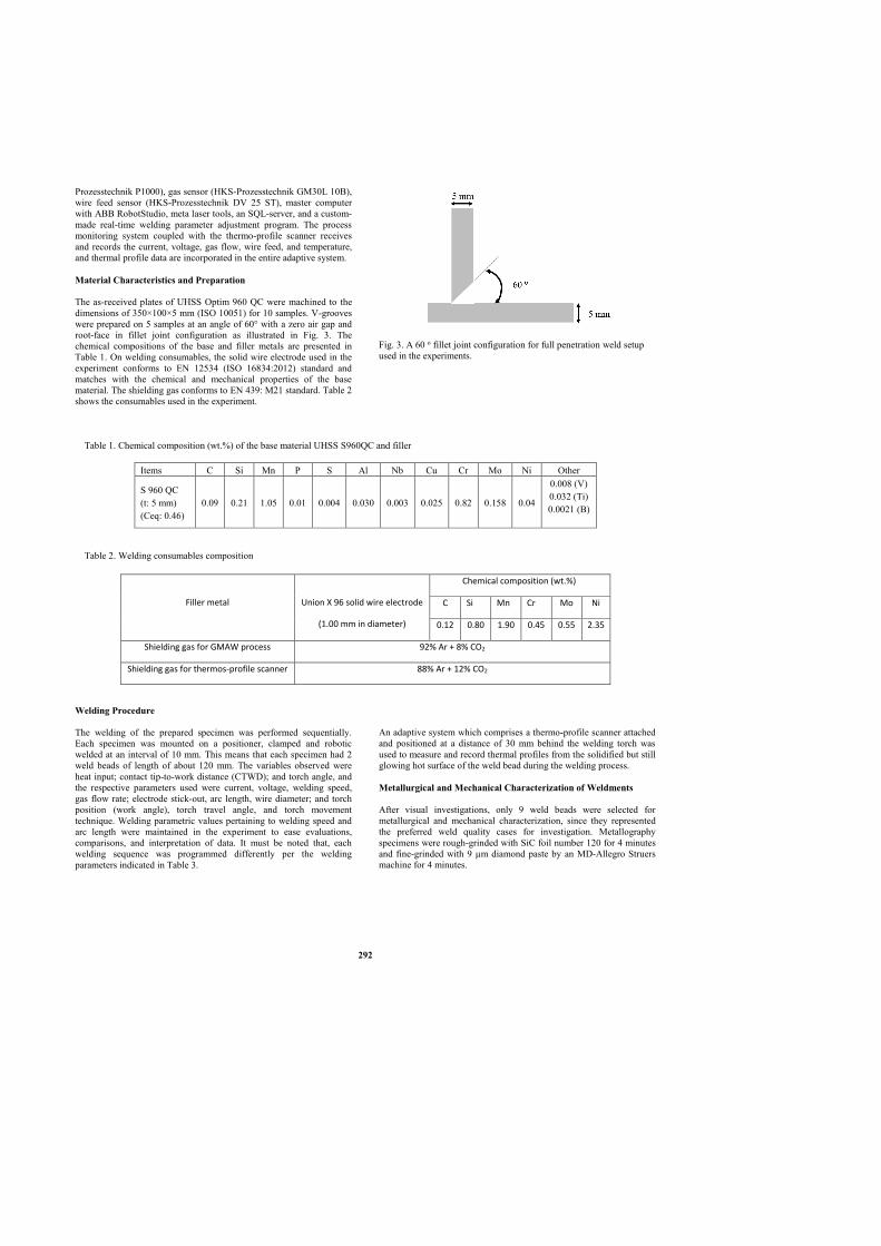
Prozesstechnik P1000), gas sensor (HKS-Prozesstechnik GM30L 10B),
wire feed sensor (HKS-Prozesstechnik DV 25 ST), master computer
with ABB RobotStudio, meta laser tools, an SQL-server, and a custom-
made real-time welding parameter adjustment program. The process
monitoring system coupled with the thermo-profile scanner receives
and records the current, voltage, gas flow, wire feed, and temperature,
and thermal profile data are incorporated in the entire adaptive system.
Material Characteristics and Preparation
The as-received plates of UHSS Optim 960 QC were machined to the
dimensions of 350×100×5 mm (ISO 10051) for 10 samples. V-grooves
were prepared on 5 samples at an angle of 60° with a zero air gap and
root-face in fillet joint configuration as illustrated in Fig. 3. The
chemical compositions of the base and filler metals are presented in
Table 1. On welding consumables, the solid wire electrode used in the
experiment conforms to EN 12534 (ISO 16834:2012) standard and
matches with the chemical and mechanical properties of the base
material. The shielding gas conforms to EN 439: M21 standard. Table 2
shows the consumables used in the experiment.
Welding Procedure
The welding of the prepared specimen was performed sequentially.
Each specimen was mounted on a positioner, clamped and robotic
welded at an interval of 10 mm. This means that each specimen had 2
weld beads of length of about 120 mm. The variables observed were
heat input; contact tip-to-work distance (CTWD); and torch angle, and
the respective parameters used were current, voltage, welding speed,
gas flow rate; electrode stick-out, arc length, wire diameter; and torch
position (work angle), torch travel angle, and torch movement
technique. Welding parametric values pertaining to welding speed and
arc length were maintained in the experiment to ease evaluations,
comparisons, and interpretation of data. It must be noted that, each
welding sequence was programmed differently per the welding
parameters indicated in Table 3.
Fig. 3. A 60 o fillet joint configuration for full penetration weld setup
used in the experiments.
An adaptive system which comprises a thermo-profile scanner attached
and positioned at a distance of 30 mm behind the welding torch was
used to measure and record thermal profiles from the solidified but still
glowing hot surface of the weld bead during the welding process.
Metallurgical and Mechanical Characterization of Weldments
After visual investigations, only 9 weld beads were selected for
metallurgical and mechanical characterization, since they represented
the preferred weld quality cases for investigation. Metallography
specimens were rough-grinded with SiC foil number 120 for 4 minutes
and fine-grinded with 9 µm diamond paste by an MD-Allegro Struers
machine for 4 minutes.
Items C Si Mn P S Al Nb Cu Cr Mo Ni Other
S 960 QC
(t: 5 mm)
(Ceq: 0.46)
0.09 0.21 1.05 0.01 0.004 0.030 0.003 0.025 0.82 0.158 0.04
0.008 (V)
0.032 (Ti)
0.0021 (B)
Table 1. Chemical composition (wt.%) of the base material UHSS S960QC and filler metal
Table 2. Welding consumables composition
Filler metal
Union X 96 solid wire electrode
(1.00 mm in diameter)
Chemical composition (wt.%)
C Si Mn Cr Mo Ni
0.12 0.80 1.90 0.45 0.55 2.35
Shielding gas for GMAW process 92% Ar + 8% CO2
Shielding gas for thermos-profile scanner 88% Ar + 12% CO2
292
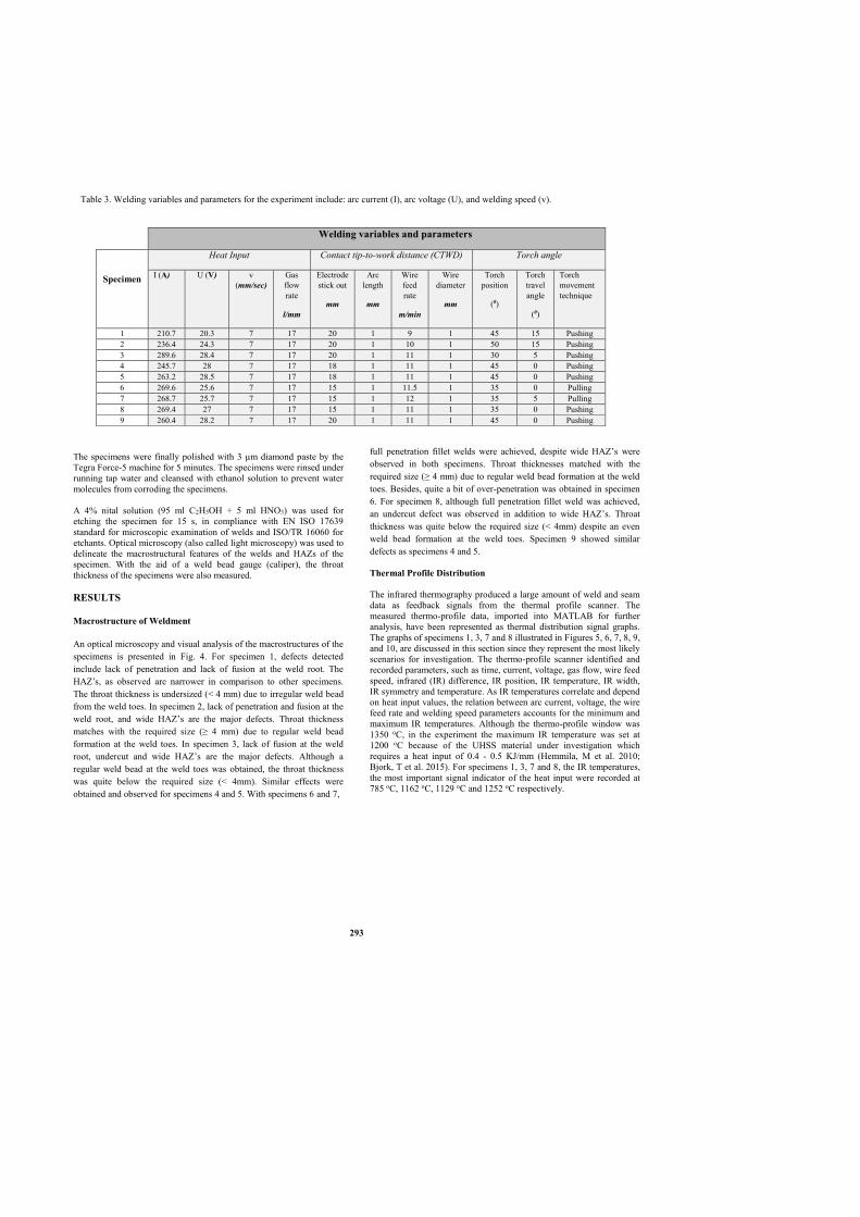
The specimens were finally polished with 3 µm diamond paste by the
Tegra Force-5 machine for 5 minutes. The specimens were rinsed under
running tap water and cleansed with ethanol solution to prevent water
molecules from corroding the specimens.
A 4% nital solution (95 ml C2H5OH + 5 ml HNO3) was used for
etching the specimen for 15 s, in compliance with EN ISO 17639
standard for microscopic examination of welds and ISO/TR 16060 for
etchants. Optical microscopy (also called light microscopy) was used to
delineate the macrostructural features of the welds and HAZs of the
specimen. With the aid of a weld bead gauge (caliper), the throat
thickness of the specimens were also measured.
RESULTS
Macrostructure of Weldment
An optical microscopy and visual analysis of the macrostructures of the
specimens is presented in Fig. 4. For specimen 1, defects detected
include lack of penetration and lack of fusion at the weld root. The
HAZ’s, as observed are narrower in comparison to other specimens.
The throat thickness is undersized (< 4 mm) due to irregular weld bead
from the weld toes. In specimen 2, lack of penetration and fusion at the
weld root, and wide HAZ’s are the major defects. Throat thickness
matches with the required size (≥ 4 mm) due to regular weld bead
formation at the weld toes. In specimen 3, lack of fusion at the weld
root, undercut and wide HAZ’s are the major defects. Although a
regular weld bead at the weld toes was obtained, the throat thickness
was quite below the required size (< 4mm). Similar effects were
obtained and observed for specimens 4 and 5. With specimens 6 and 7,
full penetration fillet welds were achieved, despite wide HAZ’s were
observed in both specimens. Throat thicknesses matched with the
required size (≥ 4 mm) due to regular weld bead formation at the weld
toes. Besides, quite a bit of over-penetration was obtained in specimen
6. For specimen 8, although full penetration fillet weld was achieved,
an undercut defect was observed in addition to wide HAZ’s. Throat
thickness was quite below the required size (< 4mm) despite an even
weld bead formation at the weld toes. Specimen 9 showed similar
defects as specimens 4 and 5.
Thermal Profile Distribution
The infrared thermography produced a large amount of weld and seam
data as feedback signals from the thermal profile scanner. The
measured thermo-profile data, imported into MATLAB for further
analysis, have been represented as thermal distribution signal graphs.
The graphs of specimens 1, 3, 7 and 8 illustrated in Figures 5, 6, 7, 8, 9,
and 10, are discussed in this section since they represent the most likely
scenarios for investigation. The thermo-profile scanner identified and
recorded parameters, such as time, current, voltage, gas flow, wire feed
speed, infrared (IR) difference, IR position, IR temperature, IR width,
IR symmetry and temperature. As IR temperatures correlate and depend
on heat input values, the relation between arc current, voltage, the wire
feed rate and welding speed parameters accounts for the minimum and
maximum IR temperatures. Although the thermo-profile window was
1350 oC, in the experiment the maximum IR temperature was set at
1200 oC because of the UHSS material under investigation which
requires a heat input of 0.4 - 0.5 KJ/mm (Hemmila, M et al. 2010;
Bjork, T et al. 2015). For specimens 1, 3, 7 and 8, the IR temperatures,
the most important signal indicator of the heat input were recorded at
785 oC, 1162 oC, 1129 oC and 1252 oC respectively.
Welding variables and parameters
Specimen
Heat Input Contact tip-to-work distance (CTWD) Torch angle
I (A) U (V) v
(mm/sec)
Gas
flow
rate
l/mm
Electrode
stick out
mm
Arc
length
mm
Wire
feed
rate
m/min
Wire
diameter
mm
Torch
position
(0)
Torch
travel
angle
(0)
Torch
movement
technique
1 210.7 20.3 7 17 20 1 9 1 45 15 Pushing
2 236.4 24.3 7 17 20 1 10 1 50 15 Pushing
3 289.6 28.4 7 17 20 1 11 1 30 5 Pushing
4 245.7 28 7 17 18 1 11 1 45 0 Pushing
5 263.2 28.5 7 17 18 1 11 1 45 0 Pushing
6 269.6 25.6 7 17 15 1 11.5 1 35 0 Pulling
7 268.7 25.7 7 17 15 1 12 1 35 5 Pulling
8 269.4 27 7 17 15 1 11 1 35 0 Pushing
9 260.4 28.2 7 17 20 1 11 1 45 0 Pushing
Table 3. Welding variables and parameters for the experiment include: arc current (I), arc voltage (U), and welding speed (v).
293

Analysis of Thermo-Profile Signals per Process Parameters
Specimen 1
The thermal profile at a temperature of 785 oC produced a blank
thermographic image of the weld bead. This is due to the heat input
(0.48KJ/mm) supplied, with low heat energy reaching the minimum IR
temperature. With the IR temperature/IR width graph, the IR width
signal, which depicts the depth of weld penetration, was virtually zero.
These observations were in agreement with the optical macroscopic
image obtained for specimen 1 in Fig. 4, which showed a lack of weld
penetration and incomplete fusion. Arc current, as a factor of the heat
input was not adequate enough to produce acceptable weld penetration.
The synergic effect of both the arc voltage and current also produced
shallow weld penetration. It has been said that the depth of penetration
or joint penetration, and the weld deposition rate are significantly
influenced by the arc current, hence the depth of penetration increases
with an increase in the arc current (Nagesh, DS and Datta, GL 2002).
On the other hand, electrode stick-out, the wire feed rate, welding
speed, torch angle and the torch movement technique were contributing
factors for inadequate weld penetration, especially where the torch
angle was set at 45o and a leading travel angle was employed (refer to
Table 3).
Technically, the trailing travel angle (pulling welding) provides
maximum penetration, and narrow and convex weld beads, whereas the
leading travel angle (pushing welding) provides flatter bead profile and adequate weld pool protection (Olson, DL et al. 1993; Cornu, J 1988).
Specimen 3
In Fig. 5, it can be seen that the thermal profile climbed to an
appreciable temperature of 1162 oC, indicating that the heat input (0.94
KJ/mm) supplied was adequate. The thermographic image of the weld
bead produced gives a clue of possible weld defects as shown in the
thermal profile pixels. Moreover, from the IR temperature/IR width
graph in Fig. 6, it can be noted that the IR width signal, which depicts
the depth of weld penetration, is above the IR temperature curve with
excessive perturbation. The relationship between Fig. 5, Fig. 6, and the
optical macroscopic image obtained for specimen 3, as depicted in Fig.
4, agrees with the defect of incomplete fusion and undercut of the weld.
In addition to this, factors such as electrode stick-out, the wire feed
rate, welding speed, and most of all the torch angle position and the
torch movement technique (pushing) could also contribute to the
observations noted.
Fig. 4. Full penetration fillet weld with test specimens showing a transverse view of macro-sections, possible defects and longitudinal throat
thickness with the aid of optical microscopy.
294

Fig. 5. Thermal profile distribution signals for specimen 3.
Fig. 6. Weld penetration versus IR temperature for specimen 3.
Specimen 7
Fig. 7 shows that the thermal profile at a temperature of 1129 oC
closely agrees with the pre-set IR temperature due to the adequacy of
the heat input (0.79 KJ/mm) supplied. The thermographic image of the
weld bead produced gives an indication of a smooth thermal profile
distribution with no major defect as shown in the thermal profile pixels.
Also, from the IR temperature/IR width graph in Fig. 8, it can be noted
agrees well with the IR temperature curve. The relationship between
Fig. 7, Fig. 8, and the optical macroscopic image obtained for specimen
7, as shown in Fig. 4, confirms the full weld penetration obtained.
Other contributing factors such as electrode stick-out, the wire feed
rate, and welding speed were set right, especially, the torch position at
35o and the trailing travel angle at 5o (pulling welding), which provided
maximum full weld penetration.
Fig. 7. Thermal profile distribution signals for specimen 7.
Fig. 8. Weld penetration versus IR temperature for specimen 7.
Specimen 8
In Fig. 9, it can be seen that the thermal profile at a temperature of 1252 oC was above the maximum pre-set IR temperature, although the heat
input (0.83 KJ/mm) supplied was quite good. The thermographic image
of the weld bead produced indicates a clipping effect at the peak of the
profile and also shows possible weld defects in the thermal profile
pixels. Therefore, when the maximum measurement temperature of the
equipment was exceeded, in the case of any splashes, the IR width of
the weld exceeded the measurement width of the thermo-profile
scanner. In the IR width graph in Fig. 10, these sections have been
replaced with a linear interpolation between the closest known
successful measurements, clearly seen as straight line segments. It can
also be noted that the IR width signal is above the IR temperature curve
with excessive perturbation due to feedback signal fluctuations from
the thermal profile. The relationship between Fig. 9, Fig. 10, and the
optical macroscopic image obtained for specimen 8, as depicted in Fig.
4, agrees with the defect of weld undercut.
295
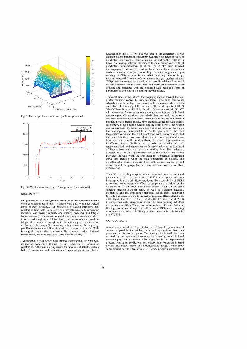
Fig. 9. Thermal profile distribution signals for specimen 8.
Fig. 10. Weld penetration versus IR temperature for specimen 8.
DISCUSSION
Full penetration weld configuration can be one of the geometric designs
when considering possibilities to assure weld quality in fillet-welded
joints of steel structures. For offshore fillet-welded structures, full
penetration fillet-weld could serve as a possible remedy to prevent or
minimize load bearing capacity and stability problems, and fatigue
failure especially in situations where the fatigue phenomenon is likely
to occur. Although most fillet-welded joint evaluations are based on
fatigue life assessment through finite element analysis, the alternative
to harness thermo-profile scanning using infrared thermography
provides real-time possibilities for quality assessment and results. With
its digital capabilities, thermo-profile scanning using infrared
thermography has been extensively employed in welding.
Venkatraman, B et al. (2006) used infrared thermography for weld bead
monitoring techniques through on-line detection of incomplete
penetration. A thermal imaging sensor for detection of defects, such as
lack of penetration, and estimation of depth of penetration during
tungsten inert gas (TIG) welding was used in the experiment. It was
claimed that the infrared thermography technique can detect any lack of
penetration and depth of penetration on-line and further establish a
linear relationship between the surface thermal profile and depth of
penetration. Chandrasekhar, N et al. (2015) also used infrared
thermography to estimate the bead width and depth of penetration in an
artificial neural network (ANN) modeling of adaptive tungsten inert gas
welding (A-TIG) process. In the ANN modeling process, image
features extracted from the infrared thermal images together with A-
TIG process parameters were used. It was established that all the ANN
models predicted for the weld bead and depth of penetration were
accurate and correlated with the measured weld bead and depth of
penetration as depicted in the infrared thermal images.
The capabilities of the infrared thermography method through thermo-
profile scanning cannot be under-estimated, practically due to its
adaptability with intelligent automated welding systems where robots
are utilized. In this study, full penetration fillet-welded joints of UHSS
S960QC have been achieved by the aid of automated robotic GMAW
with thermo-profile scanning using the adaptive features of infrared
thermography. Observations, particularly from the peak temperature
and weld penetration width curves, which were monitored and captured
through infrared thermography, have created avenues for weld quality
assessment. It has become evident that the depth of weld penetration
and the area under the temperature distribution curves either depend on
the heat input or correspond to it. As the gap between the peak
temperature curve and the weld penetration width curve widens, and
the area below these two curves decreases, it is an indication of a low
heat input with possible welding flaws, like a lack of penetration or
insufficient fusion. Similarly, an excessive perturbation of peak
temperature and weld penetration width curves indicates the likelihood
of high a heat input with possible welding flaws like under-cut.
Menaka, M et al. (2005) estimated that as the depth of penetration
increases, the weld width and area under the temperature distribution
curve also increase, when the peak temperature is attained. The
metallographic images obtained from both optical microscopy and
visual weld bead gauge (caliper) measurements corroborate these
observations.
The effects of welding temperature variations and other variables and
parameters on the microstructure of UHSS under study were not
investigated in this work. However, due to the susceptibility of UHSS
to elevated temperatures, the effects of temperature variations on the
weldment of UHSS S960QC need further studies. UHSS S960QC has a
superior strength-to-weight ratio, as well as excellent physical,
mechanical, and low-temperature properties, which enable influencing
lower fuel consumption and lower carbon emissions (Hemmila, M et al.
2010; Bjork, T et al. 2015; Kah, P et al. 2014; Laitinen, R et al. 2013)
in comparison with conventional steels. The manufacturing industries
that produce mobile offshore structures, such as offshore platforms,
floating production, storage and offloading (FPSO) units, mooring
vessels and crane vessels for lifting purposes, stand to benefit from the
use of UHSS.
CONCLUSIONS
A new study on full weld penetration in fillet-welded joints in steel
structures, possibly for offshore structural applications, has been
presented in this research paper. The novelty of this work has been
realized by incorporating thermo-profile scanning using infrared
thermography with automated robotic systems in the experimental
process. Analytical predictions and observations based on infrared
thermal distribution curves and metallographic images clearly show
some correlation and linear effects of GMAW process parameters and
296

variables, such as heat input, contact tip-to- work distance, and torch
angle, on full weld penetration in fillet-welded joints. The effects are
seen from the magnitude of the temperature curves, the depth of weld
penetration, and the area under the temperature distribution curves.
As the depth of weld penetration and the area under the temperature
distribution curves correspond to the amount of heat input supplied, a
further study to optimize the process parameters could be done through
feedback controls. In addition, the effects of welding temperature
variations and other variables and parameters on the microstructure of
the UHSS material under study could be investigated. These aspects are
relevant when considering the effects of welding temperature variations
and other parameters on the microstructure of UHSS S960QC for
offshore structural use.
Finally, in the context of digitalized welding, the ease of monitoring,
capturing, predicting and detecting weld defects, such as lack of weld
penetration, through thermal profile imaging as presented in this study,
means great potential for weld quality assurance. Thermo-profile
scanner using infrared thermography could therefore serve as a
promising alternative predicting tool for fillet-welded joints in full
penetration scenarios for quality and productivity assurance.
ACKNOWLEDGEMENT
This work was completed at the Laboratory of Welding Technology,
Lappeenranta University of Technology. The authors would like to
express their gratitude to Antti Kakkonen and Sakari Penttila for the
experiment setup. Special thanks to Antti Heikkinen for his assistance
in conducting the optical microscopy analysis and to Jukka Martikainen
for his support.
REFERENCES
ASTM International. “Standard Practice for Infrared Flash Thermography
of Composite Panels and Repair Patches used in Aerospace
Applications,” ASTM E2582-07.
Björk T, Toivonen J, Nykänen T (2015). “Capacity of Fillet Welded
Joints made of Ultra-High Strength Steel,” Doc IIW-2210,
Recommended for Publication by Commission XV Design, Analysis
and Fabrication of Welded Structures. Springer, 71-84.
Chandrasekhar, N, Vasudevan, M, Bhaduri, AK, Jayakumar, T (2015).
“Intelligent Modeling for Estimating Weld Bead Width and Depth of
Penetration from Infra-red Thermal Images of the Weld Pool,” Journal
of Intelligent Manufacturing, 26(1), 59-71.
Chokkalingham, S, Chandrasekhar, N and Vasudevan, MK (2010).
“Artificial Neural Network Modeling for Estimating the Depth of
Penetration and Weld Bead Width from the Infrared Thermal Image of
the Weld Pool during A-TIG Welding,” Springer-Verlad Berlin
Heidelberg, LNCS 6457, 270-278.
Cornu, J (1988). Advanced Welding Systems. Welding Automation,
Consumable Electrode Processes. IFS Publications Ltd, UK. 2, 301.
DNV-RP-C203 (2012). “Fatigue Design of Offshore Steel Structures,”
Det Norske Veritas AS.
Finnish Standards Association (2014). “Welding - Fusion-Welded Joints
in Steel, Nickel, Titanium and their Alloys (Beam Welding
Excluded),” Quality Levels for Imperfections (ISO 5817:2014).
Finnish Standards Association (2012). Welding Consumables – Wire
Electrodes, Wires, Rods and Deposits for Gas Shielded Arc Welding
of High Strength Steels – Classification (ISO 16834:2012).
Finnish Standards Association (2010). Continuously Hot-Rolled Strip and
Plate/Sheet cut from Wide Strip of Non-Alloy and Alloy Steels -
Tolerances on Dimensions and Shape (EN-10051:2010).
Finnish Standards Association. (2013). Destructive Tests on Welds in
Metallic Materials - Macroscopic and Microscopic Examination of
Welds (ISO 17639:2003).
Finnish Standards Association (2003). Destructive Tests on Welds in
Metallic Materials - Etchants for Macroscopic and Microscopic
Examination (ISO/TR 16060:2003).
Fricke, Wolfgang (2003). “Fatigue Analysis of Welded Joints: State of
Development,” Marine structures, 16(3), 185-200.
Fricke, W, and Doerk, O (2006). “Simplified Approach of Fatigue
Strength Assessment of Fillet-Welded Attachment Ends,”
International Journal of Fatigue, 28,141-150.
Gyasi, EA and Kah, P (2016). “Structural Integrity Analysis on the
Usability of High Strength Steels”, Rev. Adv. Mater. Sci., 46, 39-52.
Hemmilä, M, Laitinen R, Liimatainen, T, Porter D (2010). “Mechanical
and Technological Properties of Ultra-High Strength Optim Steels,”
Rautaruukki Oyj, Ruukki Production, Finland: Ruukki-Technical
Article-Mechanical-and-Technological Properties- of-Ultra-High-
Strength-Optim-Steels.pdf.
http://www.oxycoupage.com/FichiersPDF/Ruukki_Pdf/English/.
Accessed 20 April 2016.
Ibarra-Castanedo, C, Tarpani JR, Maldague XP (2013). “Non-Destructive
Testing with Infrared Thermography,” Eur J Phys, 34, 91–109.
International Institute of Welding (2008). “Recommendations for Fatigue
Design of Welded Joints and Components,” doc XIII-1539-96 /
XV845-96, Paris, France.
Kah, P, Pirinen, M, Suoranta, R, Martikainen J (2014). “Welding of
Ultra High Strength Steels,” Advanced Materials Research, 849, 357-
365.
Kainuma, S, and Mori, T (2008). “A Study on Fatigue Crack Initiation
Point of Load Carrying Fillet Welded Cruciform Joints,” International
Journal of Fatigue, 30(9), 1669-1677.
Laitinen, R, Valkonen, I, Kömi J (2013). “Influence of the Base Material
Strength and Edge Preparation on the Fatigue Strength of the
Structures made by High and Ultra-High Strength Steels,” 5th Fatigue
Design Conference, Fatigue Design. Science Direct, Procedia
Engineering, 66, 282 – 291.
Menaka, M, Vasudevan, M, Venkatraman, B and Baldev R (2005).
“Estimating Bead Width and Depth of Penetration During Welding by
Infrared Thermal Imaging,” Insight, 47(9), 564-568.
Meola, C, Boccardi, S, Carlomagno, GM, Boffa, ND, Ricci, F, Simeoli,
G, Russo, P (2017). “Impact Damaging of Composites Through Online
Monitoring and Non-Destructive Evaluation with Infrared
Thermography,” NDT&E International, Elsevier, 85, 34–42.
Nagesh, DS, Datta GL (2002). “Prediction of Weld Bead Geometry and
Penetration in Shielded Metal Arc Welding using Artificial Neural
Networks,” Journal of Materials Processing Technology, 123, 303-
312.
Olson, D L, Siewert, TA, Liu, S and Edwards, G R (1993). “Welding,
Brazing and Soldering ASM Handbook,”ASM International, 10th
edition, 6, 2872.
Radaj, D (1996). “Review of Fatigue Strength Assessment of Non-
welded and Welded Structures Based on Local Parameters,”
International Journal of Fatigue, 18(3), 153-170.
Venkatraman, B, Menaka, M, Vasudevan, M, Raj, B, (2006).
“Thermography for Online Detection of Incomplete Penetration and
Penetration Depth Estimation,” In: Asia-Pacific Conference on NDT,
5th–10th November, Auckland, New Zealand.
297

Publication IV
Gyasi, E.A., Kah, P., Handroos, H., Layus, P. and Lin, S.
Adaptive welding of S960QC UHSS for Arctic structural applications
Reprinted with permission from
International Review of Mechanical Engineering (I.RE.M.E)
Vol. 12, No. 4, 2018
© 2018, Praise Worthy Prize


International Review of Mechanical Engineering (I.RE.M.E.), Vol. 12, n. 4
Manuscript received March 2018, revised June 2018 Copyright © 2007 Praise Worthy Prize S.r.l. - All rights reserved
Adaptive Welding of S960QC UHSS for Arctic Structural Applications
Emmanuel Afrane Gyasi1, Paul Kah2, Heikki Handroos3, Pavel Layus4, Sanbao Lin5
Abstract – The construction of welded structures capable of withstanding the harsh operating
conditions found in the Arctic region is essential for effective exploitation of the area. This paper
examines the usability of S960QC UHSS as potential weldable material for lightweight Arctic
structural constructions. The paper concurrently explores the applicability of an adaptive robotic
GMAW process in welding the UHSS material. The adaptive welding system featured an infrared
thermo-profile scanner. S960QC UHSS was welded in two different fillet joint orientations
employing PA and PB welding positions. Using the adaptive welding system, the behavior of
welding parameters such as current, voltage and heat input and their effect on the temperature of
the weld seam were monitored in relation to the metallurgical properties of the welds. It was
observed that the orientation of the joint geometry influences weld penetration and the shape of
the weld. Metallurgical tests performed across the weld metal revealed that, using heat inputs
between 0.5–0.65 kJ/mm, weld hardness between 375–397 HV5 can be achieved. The hardness
values together with impact strength of 33–50 J at an operating temperature of -40 oC
demonstrate material properties suitable for Arctic structural applications where excellent
strength-to-weight ratio and high load carrying capacity are required. The paper contributes to
the field of lightweight steel construction and digitization in welding where adaptive intelligent
systems are harnessed in sensing, monitoring, predicting and modelling of the welding process for
weld quality control and assurance purposes.
Keywords: Adaptive Welding, Arctic Welded Structures, Heat Inputs, Robotic GMAW Process,
Ultra High Strength Steels (UHSS), Weld Hardness
I. Introduction
The Arctic region is known for its remote, harsh and
extremely cold climatic conditions. It is estimated that the
Arctic possesses enormous natural resources and holds
about 22% of world oil and gas reserves [1]. Other
resources such as the strong Arctic wind provide viable
opportunities for wind power industries [2]. Moreover,
global warming effects, which have resulted in shrinking
of Arctic sea ice, provide other opportunities in the
region [3]. For example, the gradual opening of the
Northern Sea Route (NSR) and the Northern passage
offer new transportation routes [4].
Tapping these resources and harnessing the
opportunities that they offer demands construction of
welded structures capable of withstanding the harsh
conditions of the Arctic. This paper examines the
usability of S960QC UHSS as weldable material for
lightweight Arctic structural constructions. The paper
further explores the applicability of an adaptive
intelligent robotic GMAW process in welding of the
S960QC UHSS material. Experimental work was carried
out to determine the effects of varying heat inputs on the
hardness properties of the weld metal, weld fusion zones
and the HAZs by comparison with the base metal.
Additionally, the effects of workpiece orientation on weld
penetration and weld shape were determined. The
experimental work was also used to evaluate the behavior
of welding parameters and variables while using the
adaptive intelligent welding system settings. The adaptive
welding system included an infrared thermo-profile
scanner attached and positioned at a distance of 30 mm
behind the welding torch to measure thermal zones from
the hot surface of the cooling weld seam during the
welding process. The adaptive welding system employs
an artificial neural network (ANN) configuration to
model the behavior of the welding parameters and
variables. Two samples were welded in the ANN
environment. The measured thermo-profile data were
then imported into MATLAB for further analysis of the
behavior of the welding parameters and variables. The
welded specimens were etched with a 4% nital solution
(95 ml C2H5OH + 5 ml HNO3) to delineate the
microstructure of the base metal and, additionally, the
macrostructural features of the welds and the HAZs of the
specimens. Light microscopy and a Vickers hardness test
machine were used for metallurgical and mechanical
analysis of the effects of heat inputs on various weld
specimens.
The paper contributes to the field of lightweight steel
construction for Arctic welded structures by study of
utilization of S960QC UHSS and digitization in welding
where adaptive intelligent systems that integrate sensors,

E.A. Gyasi, P. Kah, H. Handroos, P. Layus, S. Lin
Copyright © 2007 Praise Worthy Prize S.r.l. - All rights reserved International Review of Mechanical Engineering, Vol.
12, n. 4
monitoring systems and artificial intelligence are used for
weld quality control and assurance purposes.
II. Requirements of an Arctic Welded
Structure
Typical welded Arctic offshore structures, as illustrated
in Fig. 1, are sophisticated assemblies consisting of many
sections with different functions [5]. Different sections of
the structure usually have different material requirements
and experience different environmental conditions. A
wide range of materials with different properties are
employed in the construction of such structures. The
various sections of an Arctic offshore platform can be
classified into elements with special requirements,
general construction elements and secondary construction
elements [6]. The elements with special requirements are
responsible for the overall strength of the structure and
have to be capable of withstanding heavy loads. Such
elements include, for example, waterline construction
elements, ice-resistant girders, connection elements of
platform body parts, and elements whose cross-section
area changes considerably.
The general construction elements are used to provide
overall strength to the platform and ensure the safety of
operations. These elements include the outer cover plates
of body parts, structural frame beams, general deck cover
plates and bulkhead covers. The secondary construction
elements do not significantly influence operational safety.
Materials for the most critical and important parts of
Arctic offshore structures require special attention to
ensure that they have the necessary strength to be able to
withstand rigorous operation conditions [6].
Sections located above the waterline experience
extremely low temperatures down to -60°C, a moderately
corrosive environment (sea air) and various loads as
described in Fig. 1.
These sections have to meet the following criteria [7-9]:
Low temperature toughness down to -60°C.
Yield strength requirements up to 690 MPa.
Isotropy of properties across material dimensions to
ensure high strength.
Resistance to brittle fracture at low operational
temperatures.
Reasonable weldability with minimal preheat and
post-heat temperature required to ease the
assembly process.
Moderate corrosion resistance in sea air.
Ability to withstand static and dynamic wind and
wave loads according to the operational
parameters.
When considering transportation and installation,
weldable steels that have lightweight properties while
simultaneously meeting the above-listed requirements are
preferable for construction of the upper sections of Arctic
structures. Use of lightweight steel brings benefits from
not only reduced structural weight and cost in welding
manufacturing and production [10] but also improved
energy efficiency, which would be beneficial from the
environmental point of view. Other structures that could
harness the potential of lightweight cold-resistant
materials include knuckle-boom cranes, mobile cranes,
and Arctic vessels and icebreakers [10].
Currently, industrial Arctic offshore stationary
structures and floating drilling units typically use steel
plates up to 70 mm thickness, although some elements
can be up to 130 mm in thickness. Some icebreakers are
built of plates of thicknesses up to 60–70 mm [11]. The
use of ultra high strength steels, whose thickness is about
30-50% less than conventional steels for the same
strength [12], would make construction of welded Arctic
structures more productive and cost efficient without
sacrificing weld quality and the integrity of the whole
structure.
Fig. 1. A welded Arctic offshore platform showing the various sections and environmental conditions based on data from [5,13]

E.A. Gyasi, P. Kah, H. Handroos, P. Layus, S. Lin
Copyright © 2007 Praise Worthy Prize S.r.l. - All rights reserved International Review of Mechanical Engineering, Vol.
12, n. 4
III. Ultra High Strength Steels
Selection of weldable materials for the Arctic
environment has to be rigorous due to the low
temperature conditions, which can fall below -60 °C [14].
In addition to the cold temperatures, strong wind speeds
of about 5-15 m/s with peaks up to 50 m/s [15] can be
encountered, which makes for challenging working
conditions. Metals tend to increase in yield strength,
hardness and ultimate tensile strength, but lose their
ductility in conditions when operating temperatures drop
to sub-zero degrees [16,17] and prolonged exposure to
the cold climatic conditions of the Arctic has resulted in a
number of serious accidents in the region [16]. Advanced
structural steels like UHSS must therefore fulfil stringent
requirements, such as those listed in the previous section,
to be eligible for use in the Arctic region.
To resist brittle fracture, advanced structural steels
such as UHSS materials have to demonstrate high impact
and fracture toughness at operating and working
conditions [18]. Table I shows a typical chemical
composition of UHSS. The weldability is moderately
good since the carbon equivalent is typically 0.47
minimum and 0.52 maximum [19, 20].
UHSS exists as heat-treated steel, in other words, as
hardened steel. The process of direct quenching results in
the formation of metastable martensite, a percentage of
which is reduced to the desired amount during tempering.
UHSS thus possesses a dual-phase microstructure
consisting of fine-grained martensitic-bainitic
microstructure [19, 20].
Its microstructure, similar to advanced high-strength
steels (AHSS), is sensitive to high heat input, and
exposure to elevated temperature can change its
mechanical properties. Other critical effects of heat input
are HAZ softening and an increased propensity to fatigue
failure, which has been found to affect the toughness and
strength of welded joints of UHSS [21, 22].
Greater susceptibility to fatigue failure occurs because
during welding, where the UHSS is exposed to elevated
temperatures, the steel composition assumes an annealed
state, which leaves a softened zone in the HAZ. This
softened zone becomes over-ductile, and hardness
reduces considerably.
A typical grade of UHSS like S960QC is suitable for
lightweight manufacturing. The steel grade is hot-rolled
flat plate made of high yield strength steel for cold
forming and delivered under thermomechanical rolled
steel conditions.
The mechanical properties of S960QC are: yield
strength (900 MPa), ultimate tensile strength (1000
MPa), impact strength of 33–50 J at operating
temperature of -40 °C, and elongation of 7%. S960QC
satisfies various standards: EN ISO 148-1:2010 (impact
strength test); EN ISO 10051 (thickness, width and
length); EN 10029 (flatness, Class N, steel type H) and
EN ISO 10149-1 (tensile test) [19, 20, 23]. A potential
saving from utilizing UHSS in place of conventional steel
derives from the difference between the plate thicknesses,
for equivalent properties, of 15 mm for S 355 and 4 mm
for S 960 UHSS, which is about 73% for thickness and
93% for weld seam volume. Similarly to a 15 mm S 355
plate, a 4 mm S 960 UHSS steel plate is able to withstand
a bending moment under static load of 50 kNm [12].
A wide range of consumables for welding UHSS are
available. Filler materials of low hydrogen type (weld
hydrogen content HD ≤ 5 ml/100g) are suitable for
welding UHSS. Filler materials having such hydrogen
content are produced to meet standards like DIN EN
12534, thereby avoiding hydrogen inclusion in the weld
and ensuring low susceptibility to cold cracking. Tensile
strength class of minimum 89 (890N/mm2) is suitable for
matched consumables; while tensile strength class of
minimum 42 (minimum 420/mm2) is suitable for under-
matched consumables in welding of UHSS. Most
importantly, the maximum heat input for plate thickness
> 4 mm should be 0.5 kJ/mm and for plate thickness ≤ 4
mm should not exceed 0.4 kJ/mm. The cooling time from
800 oC to 500 oC should not exceed 4 s for high-strength
matching welds [23]. For high-strength undermatched
welds, cooling time from 800 oC to 500 oC for plate
thickness of 8 mm should not exceed 10 s [22]. Based on
its mechanical properties and chemical composition,
UHSS is prone to ductile-brittle transition (DBT), which
is a factor to be considered when evaluating welding
usability for Arctic conditions. It is reported that at DBT
temperature regions, fracture occurs as a combination of
both brittle and ductile behavior [24, 25, 26]. This
behavior is similar to fracture toughness or impact energy
temperature dependency of ferritic steels [24].
C Si Mn P S Al Nb Cu Cr Mo Ni Other
0.09 0.21 1.05 0.01 0.004 0.030 0.003 0.025 0.82 0.158 0.04
0.008 (V)
0.032 (Ti)
0.0021 (B)
TABLE I
CHEMICAL COMPOSITION OF UHSS S960QC, wt.% : CEV = C + Mn/6+ (Cr + Mo + V)/5 + (Ni + Cu)/15; 5 mm THICKNESS

E.A. Gyasi, P. Kah, H. Handroos, P. Layus, S. Lin
Copyright © 2007 Praise Worthy Prize S.r.l. - All rights reserved International Review of Mechanical Engineering, Vol.
12, n. 4
Fracture toughness remains almost constant at both lower
and upper shelves. In the transition area, fracture often
starts as ductile tearing, followed by cleavage fracture.
Since there is no exact value for the transition
temperature, some studies advise that DBT be defined
using the average temperature of both the upper and
lower limits, using a temperature that causes the fracture
mode to be 50% cleavage, or using a temperature of a
specific impact energy such as 20 J [26, 27].
Interactions between ductile collapse and brittle
fracture in DBT are important phenomena when
considering welded UHSS for Arctic applications.
Charpy-V impact tests on four martensitic UHSS
specimens with different grain sizes were performed in
[28]. The results of the study are shown in Fig. 2. It can
be seen that the sample with the smallest grain size had
the highest resistance to impact energy, about 200 J, and
the slowest ductile-to-brittle transition with respect to low
temperatures. Other research [29] also found that UHSS
experiences ductile-to-brittle transition, and it was noted
that the transition temperature might be as low as -105
°C.
Fig. 2. UHSS impact energy temperature dependency. All samples have
different grain sizes; Sample 1 has the smallest and Sample 4 the
largest grain size [28]
IV. Experimental Procedure
IV.1. Welding Apparatus
The welding apparatus consists of an adaptive GMAW
process integrated with an industrial robot. The main
features of the apparatus comprise: a robot controller,
robot manipulator, power supply with network
connections (Pulse Synergic 5000), a wire feeder,
welding torch, collision sensor, positioner, torch cleaning
and calibration station, a thermo-profile scanner sensor
monitoring system, wire feed sensor, master computer
with Robot Studio, an SQL-server, and a custom made
real-time welding parameter adjustment program. The
process monitoring system coupled with the thermo-
profile scanner receives and records the current, voltage,
gas flow, wire feed, temperature and thermal profile data.
Fig. 3 shows the experimental setup of the GMAW
intelligent adaptive welding system.
Fig. 3. GMAW adaptive intelligent setup
IV.2. Material Characteristics and Preparation
As-received plates of UHSS Optim 960 QC were
machined to the dimensions of 350×100×5 mm (ISO
10051) to produce 20 samples. The preparation of the
fillet joint configurations is as illustrated in Fig. 4. For
welding, 5 joints each were made to be welded in the PB
and PA positions respectively. The composition of the
welding consumables used is as given in Table II. The
solid wire electrode used in the experiment conforms to
EN 12534 (ISO 16834:2012) and matches with the
chemical and mechanical properties of the base material.
The shielding gas conforms to the EN 439: M21
standard.
Fig. 4. Fillet weld configurations where a) is the PB welding position
and b) the PA welding position
TABLE II
COMPOSITION OF WELDING CONSUMABLES
Filler
metal
Union X
96 solid
wire
electrode
(1.00
mm in
diameter)
Chemical composition (wt. %)
C Si Mn Cr Mo Ni
0.12 0.80 1.90 0.45 0.55 2.35
Shielding gas for GMAW process
92% Ar + 8% CO2
Shielding gas for thermos-profile scanner
88% Ar + 12% CO2

E.A. Gyasi, P. Kah, H. Handroos, P. Layus, S. Lin
Copyright © 2007 Praise Worthy Prize S.r.l. - All rights reserved International Review of Mechanical Engineering, Vol.
12, n. 4
IV.3. Welding Procedure
Welding of the prepared samples was performed
sequentially. Each welding sequence was programmed
differently per the welding parameters indicated in Table
III. Each specimen was mounted on a positioner, clamped
and welded with the adaptive robotic GMAW process.
Welding parametric values pertaining to welding speed,
gas flow rate, electrode stick, arc length, wire diameter,
torch position and torch travel angle were maintained
constant to ease evaluation, comparison and
interpretation of data. Key welding parameter values
were gas flow rate, 17.7 l/mm; arc length, 1.0 mm; and
wire diameter, 1.0 mm. The arc efficiency of the GMAW
process used for determination of the heat input values
was 0.8. The adaptive GMAW process included a
thermo-profile scanner attached and positioned at a
distance of 30 mm behind the welding torch, which was
used to measure and record thermal heat from the
solidified but still glowing hot surface of the weld seam
during the welding process. After visual examination,
eight (8) samples were presented for analysis.
The adaptive welding system employs an ANN
configuration to model the behavior of the welding
parameters and variables. Welding parameters for two
samples were fed into an already-existing ANN modelled
system and the parameters were adjusted by a few
welding trails.
The measured thermo-profile data were then imported
into the MATLAB environment for further analysis of the
behavior of the welding parameters and variables. Two
samples, denoted PA ANN and PB ANN, were welded
using the ANN modelled system.
IV.4. Metallurgical and Mechanical Characterization
Metallography specimens were rough-ground for 4
minutes with SiC foil number 120 and fine-ground with 9
µm diamond paste for 4 minutes using an MD-Allegro
Struers machine. The specimens were finally polished
with 3 µm diamond paste for 5 minutes using a Tegra
Force-5 machine. The specimens were rinsed under
running tap water and cleansed with ethanol solution to
prevent water molecules from corroding the specimens.
A 4% nital solution (95 ml C2H5OH + 5 ml HNO3)
was used to etch the specimens for 15 s, in compliance
with EN ISO 17639 standard for microscopic
examination of welds and ISO/TR 16060 for etchants.
Light microscopy was used to delineate the
microstructure of the base metal and the macrostructure
features of the welds and HAZs of the specimen.
Specimen
Heat Input Contact tip-to-work
distance (CTWD)
Torch angle
I (A) U (V) v (mm/sec) Electrode
stick out
(mm)
Wire
feed rate
(m/min)
Torch
position
(0)
Torch
travel
angle
(0)
Torch
movement
technique
1 (PB ANN) 200.1 22.1 7.0 18.0 9.69 40 5 Pushing
2 (PA ANN) 202.2 22.3 7.0 18.0 9.37 90 0 Pushing
3 (PB 1) 213.6 24.3 7.0 18.0 10.31 40 5 Pushing
4 (PA 1) 232.1 26.2 7.0 18.0 10.27 90 0 Pushing
5 (PB 2) 204.7 26.2 7.0 18.0 8.90 40 5 Pushing
6 (PA 2) 211.7 26.1 7.0 18.0 8.87 90 0 Pushing
7 (PB 3) 195.7 24.6 7.0 18.0 8.90 40 5 Pushing
8 (PA 3) 208.9 24.6 7.0 18.0 8.90 90 0 Pushing
TABLE III.
WELDING VARIABLES AND PARAMETERS FOR THE EXPERIMENT INCLUDE: ARC CURRENT (I), ARC VOLTAGE (U), AND
WELDING SPEED (v)

E.A. Gyasi, P. Kah, H. Handroos, P. Layus, S. Lin
Copyright © 2007 Praise Worthy Prize S.r.l. - All rights reserved International Review of Mechanical Engineering, Vol.
12, n. 4
V. Results
V.1. Microstructure of the Base Metal
The microstructure of the base metal S960QC UHSS
is illustrated in Fig. 5. The presence of martensite in the
crystal lattice is reflected as needlelike microstructure,
while the presence of bainite is seen as dark portions in
the crystal lattice [30]. Under welding conditions, the
basic microstructure can change significantly depending
on the heat inputs applied, the type of consumables used,
transformation or dislocation of the crystalline structure,
and diffusion of the alloying elements.
Fig. 5. Fine-grained martensite-bainite morphologies of UHSS
S960QC: a) Light micrograph, length of micron bar 100 µm. b) SEM
analysis using back-scattered electron approach.
V.2. Macrostructure of weldments
Light microscopy images of the macrostructures of
chosen specimens are given in Fig. 6. Generally, the
macrostructure of the specimens for horizontal flat
welding position (PA) show deeper weld penetration at
the weld root than with horizontal welding position (PB).
The finger weld characteristics of the GMAW process is
well pronounced in the PA welding position. Also, the
shape of the surface profile of the weld beads look flatter
from the top weld toe to the down weld toe, especially
with the PA welding position. No major weld defect or
imperfection is noticed in the specimens. The quality
levels (surface and internal imperfections) of the
specimens conform to EN 1SO 5817. Throat thicknesses,
measured with a weld bead gauge (caliper), fall within
the range of 0.5*t – 0.7*t, where t is the thickness of the
base metal (5 mm). Therefore, the weld thicknesses were
≥ 2.5 or ≤ 3.5. The percentage of dilution of the filler
wire and the base metal, based on the heat inputs
supplied, was commensurate with the throat thicknesses
achieved.
Comparing weld specimens PB ANN and PA ANN,
the heat input applied was of the same value, with slight
variation. However, due to the welding position of PA
ANN, the heat input produced high arc pressure causing
deeper weld penetration. Contrarily, the cooling rate in
PA ANN was much slower than PB ANN. This slower
cooling is a result of the amount of heat retained at the
weld toe, causing slower dissipation of heat than with PB
ANN. The same phenomenon was observed in the other
specimens (PB 1, PA 1, PB 2, PA 2, PB 3 and PA 3). By
visual examination, the PB welding position shows non-
uniform HAZs across the base member and the upright
member. Although in PA the HAZs are also large, there
was uniformity in how the heat spreads across the joints.
Another significant finding is that although PB 2 had
higher heat input than PA 2, the cooling rates were quite
similar. This observation affirms that there is a much
faster cooling rate in the PB welding position than the PA
position for the same or slightly higher heat input (say,
0.05 kJ / mm difference).
V.3. Behavior of the Welding Parameters and
Variables
The behavior of the various welding parameters has a
direct effect on the temperature of the weld seam, thus
causing non-uniform thermal cycles in the weld and
surrounding zones. By comparing the temperature graphs
of the PB welding positions in Fig. 7, it can be seen that
the temperature readings did not exceed 1100 °C with a
heat input range from 0.50–0.65 kJ/mm. However, from
the temperature graphs of PA for the same heat input
range, it can be seen that the temperature captured from
the surface of the weld seam peaked above 1100 °C. Heat
input readings of PA 1 and PA 3 show similar stability to
readings for PB 1 and PB 3. Arc length, wire feed,
voltage and current reading were quite stable. It can be
said that arc stability is very much achieved in the PA
welding position, and thus change of the mode of metal
transfer from short-circuit arc to spray arc is smooth.
The behavior of the welding parameters observed for
PA ANN and PB ANN shows more unstable curves than
with the other specimens. Although arc length and wire
feed rate were quite stable, there are severe fluctuations
in voltage, current, and heat input readings, which could
be a result of disturbances in the adaptive welding
system. Such disturbances may have affected the amount
of heat input supplied during welding, thus keeping the
weld seam temperature below 1100 oC. The observed
behavior might also be due to the change in the mode of
metal transfer from short-circuit arc to spray arc, which
the ANN system tried to modify, or to which it did not
compensate. The driving forces (electrostatic force,
Marangoni force, buoyancy force, inertia, surface tension
and viscosity) involved in the GMAW process [31] might
have influenced the behavior of the welding parameters
and variables in the different welding positions.

E.A. Gyasi, P. Kah, H. Handroos, P. Layus, S. Lin
Copyright © 2007 Praise Worthy Prize S.r.l. - All rights reserved International Review of Mechanical Engineering, Vol.
12, n. 4
Fig. 6. Light microscopy images (2 mm scale) of test specimens showing a transverse view of macro-sections and longitudinal throat
thickness.

E.A. Gyasi, P. Kah, H. Handroos, P. Layus, S. Lin
Copyright © 2007 Praise Worthy Prize S.r.l. - All rights reserved International Review of Mechanical Engineering, Vol.
12, n. 4
Fig. 7. Behavior curves of welding parameters of selected specimens: (a) PA ANN, (b) PB ANN, (c) PA 1, (d) PB1, (e) PA 3 and (f) PB 3
(a) (b)
(c) (d)
(e) (f)

E.A. Gyasi, P. Kah, H. Handroos, P. Layus, S. Lin
Copyright © 2007 Praise Worthy Prize S.r.l. - All rights reserved International Review of Mechanical Engineering, Vol.
12, n. 4
VI. Hardness Analysis
The Vickers hardness of the base metal at a load of
HV5 varies from 351–356 HV measured at intervals of 1
mm. For comparison, the Vickers hardness values across
the surface of the weld metal is similar in the PA ANN
and PB ANN specimens. The highest hardness values
obtained ranged from 375–397 HV5. However, at the
fusion boundaries, the hardness values of the PA ANN
specimen dropped to about 295 HV5 on the left side and
303 HV5 on the right side of the joint geometry, as
shown in Fig. 8. Notably, there was no significant drop in
hardness at the fusion line of the PB ANN specimen, as
seen in Fig. 9.
A drop in hardness was recorded at the HAZs in both
welding positions. PA ANN recorded a more pronounced
drop in hardness towards the base metal (non-HAZ).
Considering the heat input applied, it can be seen that in
the PA ANN and PB ANN specimens, the maximum
percentage drop in hardness across the fusion boundaries
to the base metal is about 26% to 24%, respectively
(using minimum hardness values). Interestingly, it can be
seen from the graph of PA ANN in Fig. 7 that when heat
input was within the range of 0.50–0.65 kJ/mm, the
temperature fluctuation reading did not peak above 1100 oC. This could be a result of the welding parameters
being modified by the ANN system.
Comparing PA 3 and PB 3, it can be seen in Fig. 10
and Fig. 11 that PB 3 had higher hardness values at the
surface of the weld metal than PA 3. Considering the heat
input applied, it can be seen that in PA 3 and PB 3, the
maximum percentage drop in hardness across the fusion
boundaries to the base metal is about 21% to 16%,
respectively (using minimum hardness values).
In PA welding positions, that is Fig. 8 and Fig. 10, the
drop in hardness is quite uniform from the HAZ to the
base metal on both sides of the welded joint. Moreover,
hardness values across the surface of the weld metal are
uniform due to the flatness of the weld bead profile. In
PB welding positions, that is Fig. 9 and Fig 11, the drop
in hardness is more pronounced towards the upright
member than the base member, especially at the fusion
boundary and also in the HAZ. Although there is
progressive drop in hardness towards the base metal
(non-HAZ), the upright member experienced the greatest
drop in hardness.
Fig. 8. Hardness test of specimen PA ANN
Fig. 9. Hardness test of specimen PB ANN
Fig. 10. Hardness test of specimen PA 3
Fig. 11. Hardness test of specimen PB 3
Scale: 1 mm
Scale: 1 mm
Scale: 1 mm
Scale: 1 mm
E.A. Gyasi, P. Kah, H. Handroos, P. Layus, S. Lin
Copyright © 2007 Praise Worthy Prize S.r.l. - All rights reserved International Review of Mechanical Engineering, Vol.
12, n. 4
VII. Discussions
Having an impact strength between 33–50 J at an
operating temperature of -40 oC, the UHSS under study
meets the requirements of materials for use in Arctic
structures. However, to ensure that such material can be
used successfully in the Arctic environment, there is a
need to consider controlled and intelligent approaches in
welding of UHSS. Welding operations with uncontrolled
heat inputs introduce high stress concentrations in welded
UHSS, especially when there are imperfections and
defects such as softening of the HAZ [22]. In such cases,
the grain sizes of the weld fusion line and the HAZ may
become large and service performance will be
compromised. Research on UHSS materials with
different grain sizes [28] attests to this phenomenon.
Two fillet weld joint configurations of UHSS S960QC
are studied in this paper and their suitability for Arctic
structural applications considered. The adaptive robotic
GMAW system employed provided opportunities for
monitoring, predicting and modifying the behavior of the
welding parameters and variables. Some of the specimens
were welded while the system was operating from an
ANN configuration. The results of the welding
experiment produced meaningful findings on the effects
of varying heat inputs on the hardness properties of the
weld geometry and the influence of the behavior of the
welding variables and parameters on weld temperature.
It was observed that the ANN configuration had a
great influence on the behavior of the welding parameters
and variables, which changed without showing a
significant effect on temperature. However, those
specimens that were welded without the ANN system
experienced susceptibility to high temperatures even
though the heat inputs supplied during welding were
quite similar. High temperatures as a result of heat input
effects could produce HAZ softening tendencies and low
cooling rates, which is a risk and, moreover, detrimental
to the welded structure.
Although all the welded joints had satisfactory weld
fusion, PA welds had deeper weld penetration than welds
welded in the PB position. In hardness tests performed
for both fillet joint configurations, PB welded joints
produced more satisfactory hardness values across the
weld geometry than PA. This suggests that PB welded
joints should be preferred for Arctic structural
constructions where considerable load carrying capacity
is required. However, the base member of the PB welded
joint should be the load carrying member since the drop
in hardness was lower in this region. Alternatively, PA
welded joints could be used where stiffening of an Arctic
structural member is required because the hardness
properties were uniform across the weld geometry.
Nevertheless, PA could also be used where load carry
capacity is required due to the deeper weld penetration
achieved.
Based on this work, it can be seen that using an
adaptive intelligent GMAW system is beneficial for
welding of lightweight materials like UHSS for Arctic
structural constructions. Other work has also reported the
applicability of the adaptive GMAW process for UHSS
[32, 33]. Implementation of adaptive GMAW processes
in the future welding industry looks promising as the
approach brings benefits from digitalization (online and
offline welding) [34] and interaction between robots,
humans and intelligent system protocols that increase
productivity and quality [35].
In future work, further investigation and analysis of
the microstructure of the welded metal and the HAZs is
required. Additionally, from the perspective of system
integration, a control algorithm could be developed to
control the amount of heat input supplied to the weld or
to optimize the entire welding system.
VIII. Conclusion
The objective of this work was to examine the usability
of S960QC UHSS as weldable material for lightweight
Arctic structural constructions and, further, to explore the
applicability of intelligent adaptive techniques in welding
of S960QC UHSS. Adaptive robotic GMAW of 5 mm
S960QC UHSS plates in two fillet joint configurations
was performed. The fillet joints were welded in PA and
PB welding positions. 8 specimens were analyzed to
assess the effects of varying heat inputs on the hardness
properties of the weld metal, weld fusion zones and the
HAZs. In addition, the behavior of welding parameters
and variables while using the adaptive intelligent welding
system settings was appraised. Applied heat inputs in the
range 0.5–0.65 kJ/mm produced weld hardness values
between 375 HV5 and 397 HV5. The hardness values
together with impact strength of 33–50 J, at operating
temperature of - 40 oC, indicate that S960QC UHSS has
properties suitable for Arctic structural applications
where excellent strength to weight ratio and high load
carrying capacity is required. However, the susceptibility
of S960QC UHSS to HAZ softening is a critical issue
that needs attention. Careful selection of consumables,
welding processes and techniques, and the adoption of
appropriate control mechanisms for the welding process
is recommended. It is also important to consider the
cooling rate of the weld since it affects the
microstructural properties. In assessment of the
applicability of intelligent adaptive welding, it was found
that the system was beneficial for monitoring, capturing,
predicting, detecting and modifying the behavior of the
welding parameters and variables. After further
development, the adaptive intelligent welding system
could potentially be used to control and optimize welding
operations and thus increase welding productivity and
weld quality.

E.A. Gyasi, P. Kah, H. Handroos, P. Layus, S. Lin
Copyright © 2007 Praise Worthy Prize S.r.l. - All rights reserved International Review of Mechanical Engineering, Vol.
12, n. 4
Acknowledgements
This research was carried out at Lappeenranta University
of Technology in collaboration with the State Key
Laboratory of Advanced Welding and Joining, Harbin
Institute of Technology, China. The work received
financial support from an Academy of Finland grant
awarded to Lappeenranta University of Technology,
Laboratory of Welding Technology project ‘Monitoring
and Modelling of Advanced Adaptive Welding Process
Systems for Ultra High Strength Steel (UHSS)’ and
Laboratory of Intelligent Systems project ‘Manufacturing
4.0 – Strategies for Technological, Economical,
Educational and Social Policy Adoption’. The authors
would like to thank Peter Jones for his comments and
assistance with the English language, and Esa Hiltunen
and Sakari Pentillä for their support during the
experimental work.
References
[1] P. Budzik, Arctic Oil and Gas Potential, Publications of US
Energy Information Administration Office of Integrated Analysis
and Forecasting Oil and Gas Division, 2009.
[2] J. Lancaster, Handbook of Structural Welding Processes,
Materials and Methods Used in the Welding of Major Structures,
Pipelines and Process Plant (3rd edition, Cambridge, 2003).
[3] O.N. Knut, The Arctic – A Region of Opportunities and Interest.
Stiftelsen Det Norske Veritas Germanischer Lloyd (DNV.GL),
2012.
[4] K. Paananen, Opportunities for Finland – the Arctic and Russia,
Baltic Rim Economics, Quarterly Review 3, Expert Article 1267,
2013.
[5] A. Khaustov, New cold-resistant steel for shipbuilding,
Sudostroenie, Vol 4, pp 57-58, 2006.
[6] I. Novitsky, A. Portnoy, V. Razuvaev, V, Handbook of Design of
Offshore Platforms: Requirements of Standards (Teoksessa, Saint
Petersburg, Russia: SPbGMTU, 2009) (in Russian).
[7] I.V. Gorynin, V.V. Rybin, V.A. Malyshevskii, E.I. Khlusova,
Alloying principles, phase transformation, structure and
properties of low-temperature weldable shipbuilding steels, Metal
Science and Heat Treatment, Vol. 49, n. 1-2, pp. 3-9, 2007.
[8] P.D. Odessey, Microalloying of steels for the North and unique
metal structures, Intermet Engineering, pp.176, 2006.
[9] P. Layus, P. Kah, M. Kesse, E.A. Gyasi, Submerged Arc Welding
Process in Welding Thick High Strength Steel Plates Used for
Arctic Applications, Proc. 27th International Ocean and Polar
Engineering Conference, San Francisco, CA, USA June 2017, pp.
92-98.
[10] P. Layus, P. Kah, J. Martikainen, V. Gezha, Advanced SAW
processes for Arctic structures and ice-going vessels, Proceedings
of the Institution of Mechanical Engineers, Part B: Journal of
Engineering Manufacture, Vol.232(1), pp.1-14, 2018.
[11] A. Ilyin, Presentation at Prometheus seminar, Saint Petersburg,
2013.
[12] Alform, Superior Solutions in High-Strength and Ultra-High-
Strength TM steel, Voestalpine Steel Division, 17th edition.
[Online]
alform_Produktfolder_Hochfeste_und_Ultrahochfeste_TM_EN_1
401.pdf. Accessed 5.1.2018.
[13] P. Layus, P. Kah, J. Martikainen, Peculiarities of Welding
Technical Requirements for Arctic Applications, Proc. 25th
International Ocean and Polar Engineering Conference (Hawaii,
USA June 2015), pp. 285-288.
[14] M.C. Serreze, R.G. Barry, The Arctic Climate System (2nd
edition, Cambridge University Press, 2005).
[15] R. Przybylak, The Climate of the Arctic, Springer, pp. 288, 2003.
[16] J.P. Kaushish, Manufacturing Processes, PHI Learning Pvt. Ltd,
1007, 2008.
[17] T.L. Anderson, H.I. McHenry, Interim Progress Report: Fracture
Toughness of Steel Weldments for Arctic Structures, NBSIR 83-
16980, Colorado 80303, 1982.
[18] P. Layus, P. Kah, E. Khlusova, V. Orlov, Study of the sensitivity
of high-strength cold-resistant shipbuilding steels to thermal cycle
of arc welding, International Journal of Mechanical and
Materials Engineering, Vol.13(3), pp.1-9, 2018.
[19] D. Porter, Development in Hot-Rolled High-Strength Steel,
Nordic Welding Conference, New Trends in Welding
Technology, Tampere, Finland, 2006.
[20] M. Hemmilä, R. Laitinen, T. Liimatainen, D. Porter, Mechanical
and Technological Properties of Ultra High Strength Optim
Steels, Rautaruukki Oyj, Helsinki. [Online]
http://www.oxycoupage.com/FichiersPDF/Ruukki_Pdf/English/R
uukki-Technical-article-Mechanical-and-technological-
properties-of-ultra-high-strength-Optim-steels.pdf. Accessed 18.1
2018.
[21] P. Kah, M. Pirinen, R. Suoranta, J. Martikainen, Welding of ultra
high strength steels, Advanced Materials Research, Vol. 849, pp.
357-365, 2014.
[22] T. Björk, J. Toivonen, T. Nykänen, Capacity of fillet welded
joints made of ultra-high strength steel, Weld World, Vol. 57, pp.
71–84, 2012.
[23] Ruukki Metals, Hot Rolled Steel Plates, Sheets and Coils –
Processing of Materials- Impact Strength and Through Thickness
Properties. Helsinki, 2007.
[24] Z.A. Chen, Z. Zeng, Y.J. Chao, YJ, Effect of crack depth on the
shift of the ductile–brittle transition curve of steels, Engineering
Fracture Mechanics, Vol. 74, n.15, pp. 2437–2448, 2007.
[25] N.E. Dowling, Mechanical Behavior of Materials. Engineering
Methods for Deformation, Fracture, and Fatigue (3rd edition,
Upper Saddle River, New Jersey: Pearson Education, Inc., 912,
2007).
[26] F. Dominique, P. Andre, Z. Andre, Mechanical Behaviour of
Material”. Volume II: Fracture Mechanics and Damage,
Dordrecht Springer, pp. 662, 2013.
[27] W.D. Callister, D.G. Rethwisch, Materials Science and
Engineering (6th edition, John Wiley & Sons, 2007).
[28] F. Zhen, K. Zhang, Z. Guo, J. Qu, Effect of martensite fine
structure on mechanical properties of an 1100 MPa grade ultra-
high strength steel, Journal of Iron and Steel Research,
International, Vol.22, pp. 645–651, 2015.
[29] X. Wu, H. Lee, Y.M. Kim, N.J. Kim, Effects of processing
parameters on microstructure and properties of ultra high strength
line-pipe steel, Journal of Materials Science & Technology, Vol.
28, pp. 889–894, 2012.
[30] B.C. Howard, C.H. Scott, Modern Welding Technology (6th
edition, Pearson Prentice Hall, USA, 2005).
[31] A. Kumar, T. Debroy, Heat transfer and fluid flow during gas-
metal-arc-fillet welding for various joint configuration and
welding positions, Metallurgical and Materials Transactions A,
Vol. 38A, pp. 506-519, 2007.
[32] E.A. Gyasi, P. Kah, J. Ratava, M. Kesse, E. Hiltunen, Study of
Adaptive Automated GMAW Process for Full Penetration Fillet
Welds in Offshore Steel Structures, Proc. 27th International
Ocean and Polar Engineering Conference, San Francisco, CA,
USA June 2017, pp. 290-297.
[33] E.A. Gyasi, P. Kah, H. Wu, M.A. Kesse, Modeling of an artificial
intelligence system to predict structural integrity in robotic
GMAW of UHSS fillet welded joints, Int J Adv Manuf Technol.
Vol. 93, pp. 1139-1155, 2017.
[34] E.A. Gyasi, P. Kah, Structural integrity analysis of the usability of
high strength steels. Rev. Adv. Mater. Sci, Vol. 46, pp: 39-52,
2016.
[35] J.N. Pires, A. Loureiro, G. Bölmsjo, Welding robots: Technology,
system issues and applications. Springer-Verlag London Limited.
pp.180, 2006.

E.A. Gyasi, P. Kah, H. Handroos, P. Layus, S. Lin
Copyright © 2007 Praise Worthy Prize S.r.l. - All rights reserved International Review of Mechanical Engineering, Vol.
12, n. 4
Authors’ information
1Laboratory of Welding Technology, Department of Mechanical
Engineering, School of Energy Systems, Lappeenranta University of
Technology, Lappeenranta, Finland.
[email protected]; [email protected] 2Laboratory of Welding Technology, Department of Mechanical
Engineering School of Energy Systems, Lappeenranta University of
Technology, Lappeenranta, Finland.
[email protected] 3Laboratory of Intelligent Systems, Department of Mechanical
Engineering, School of Energy Systems, Lappeenranta University of
Technology, Lappeenranta, Finland.
[email protected] 4Laboratory of Welding Technology, Department of Mechanical
Engineering, School of Energy Systems, Lappeenranta University of
Technology, Lappeenranta, Finland.
[email protected] 5State Key Laboratory of Advanced Welding and Joining, Harbin
Institute of Technology, Weihai, China.
Emmanuel Afrane Gyasi was born in Accra,
Ghana. He earned a B.Eng. (Industrial
Management) in 2010 from Savonia University
of Applied Sciences, Finland, and M.Sc.
(Mechanical Engineering) in 2013 from
Lappeenranta University of Technology,
Finland.
He has published 7 scientific journals and
conference papers in the field of welding technology. His current
research interests include automation, robotics, artificial intelligence,
steel structures and advanced welding processes.
Mr. Gyasi is a member of the Finnish Welding Society (SHY) and
serves on the International Institute of Welding (IIW) technical
commissions (C-II, C-IX and C-XII). Mr. Gyasi is the founder of the
Ghanaian Institute of Welding, and currently acts as the President and
CEO of the organization.
Paul Kah obtained a professional Master’s
degree certificate, DIPET II, from ENSET at
the University of Douala, Cameroon, in 2001
and graduated from Lappeenranta University
of Technology, Finland with a second MSc
(Tech) in 2007.
He completed his doctoral studies at
Lappeenranta University of Technology in
2011. He has a position of Associate Professor and has published about
150 scientific papers in peer-reviewed scientific journals and
conference proceedings.
Docent Kah is an expert in the International Institute of Welding (IIW)
Commission IX, XII, C-XII-A, and a guest editor of Welding in the
World and a reviewer in IEEE. Docent Kah is the President (Chairman)
of Cameroon Welding Association.
Heikki Handroos was born in Tampere,
Finland. He earned an M.Sc. (Eng.) in 1985 and
a D.Sc. (Tech.) in 1991 in Hydraulics and
Automation from Tampere University of
Technology, Finland.
He has published 250 journal and conference
papers in the field of mechatronics and robotics.
Professor Handroos is a member of ASME and IEEE. Currently he is
an Associate Editor of ASME Journal of Dynamic Systems,
Measurement and Control. Professor Handroos is a Full Professor in
Machine Automation in the Department of Mechanical Engineering,
Lappeenranta University of Technology
Pavel Layus was born in St. Petersburg
(Russia). He earned his doctoral degree from
Lappeenranta University of Technology
(Finland) in the field of welding technology for
low temperature shipbuilding applications
(2017).
He is the first author of about 15 academic and
conference papers on various topics related to
welding and material science.
Dr. Layus has been a member of Finnish Welding Society (SHY) since
2013 and received a SHY silver medal for outstanding doctoral
dissertations in the field of welding.
Sanbao Lin obtained a B.S., M.S., and Ph.D.
degrees from Harbin Institute of Technology,
Heilongjiang, China in 1994, 1996, and 2000,
respectively.
He has been working at the State Key
Laboratory of Advanced Welding and Joining
at Harbin Institute of Technology since 2000.
He has authored and co-authored over 150
papers in peer-reviewed journals.
Professor Lin research interest includes are welding procedure and
process control. Professor Lin has had research stay at the University of
Cambridge in UK.

Publication V
Gyasi, E.A., Pirinen, M., Nallikari, M. and Martikainen, J.
Transforming Arctic welding with Finnish technological know-how
Reprinted with permission from
Canadian Welding Association (CWA) Journal - Special CWA-IIW Conference Edition
pp. 80-87, 2014
© 2014, CWA Journal
Reprinted with permission from
Canadian Welding Association (CWA) Journal - Special CWA-IIW Conference Edition
pp. 82-91, 2015© 2015, CWA Journal


Transforming Arctic Welding with FINNISH TECHNOLOGICAL KNOW-HOWThe Arctic region is known for its remote, harsh, and
extremely cold climatic conditions. It is estimated that, the Arctic region which possesses enormous natural resources hold about 22% of oil and gas reserves [1]. Other resources such as the strong Arctic wind also provide viable opportunitiesfor wind power industries [2]. Moreover, global warmingsituations which have resulted in Arctic ice shrinking provide other opportunities in the region [3]. The gradual opening of the Northern Sea Route (NSR), due to climate changes, thus offer new transportation routes in the region [4].
In recent times, the Arctic region is increasingly being seen as a potentially sustainable area for infrastructural and productdevelopment due to continuous efforts to tap resources which were once considered commercially unrecoverable. The development of the Arctic region has become necessaryin other to exploit the un-tapped opportunities, whiles protecting the fragile ecosystem [5]. The entire development of the Arctic region, however, demands huge investment to facilitate construction of structures such as ships, tankers, vessels, pipelines, communication and energy production structures capable to resist brittle fracture in the harsh Arctic conditions. As these structures are mostly constructed with metals and predominantly joined through welding, the accurate selection of weldable materials such as high strength steels, and suitable welding processes are stringent requirements. There is a need for corporate effort through cooperation and partnerships to developing the Arctic region. Finland
JOURNAL 82

demonstrates high technological and undoubtable expertise in welding due to exceptions made in material and welding process selections for Arctic structural construction.Following long tradition in shipbuilding, about 60% of all icebreakers in the world have been designed and built in Finland [6], based on strong expertise in research and development, specialities in the construction of technically demanding vessels, systematic industrial innovative processes,networking, and procedures for welding of structures for Arctic operations [6, 7].
This paper evaluates Finland’s welding expertise and tech-nological know-how relevant to development of the Arctic region. The study emphasizes the need for business part-nerships to harness un-tapped opportunities in the Arctic region and also draws attention to international cooperation and networking for multidisciplinary research in the field of Arctic Welding, as economic activities and infrastructure in Arctic condition have become paramount. It is such that Finland’s position in Arctic operations is strong and thus serves as a safe and reliably bridge for other nations to participate in developing Arctic welding activities.
1. WELDABLE METALS FOR ARCTIC STRUCTURES The selection of weldable materials for the Arctic environmenthas been rigorous due to the low temperature conditions which could fall below -60 0C [8]. Weldable materials selectedfor applications in the Arctic region must therefore fulfill stringent requirements such as: low temperature toughnessdown to -60 0C; yield strength up to 690 MPa; Isotropy properties across dimensions [9, 10]. Additionally, as the natural environment of the Arctic region is harsh with strong wind velocity of about 5-15 m/s up to 50 m/s [11], the selec-tion of weldable materials are required to fulfill working conditions as well since continual exposure of materials to the cold climatic conditions has resulted in several detrimentalaccidents in the region [12].
As a phenomenon, metals tend to increase in yield strength, hardness and ultimate tensile strength but lose their ductilityin conditions when operating temperatures go down to sub-zero degrees [12, 13]. In view of this, weldable materials for the Arctic region are expected to demonstrate high impact and fracture toughness at operating and working conditionto resistance brittle fracture. While impact toughness is determined by Charpy V-notch test, fracture toughness is either determined by the crack tip opening displacement (CTOD) test or the crack tip opening angle (CTOA) [14,15].
Due to the wider range of materials and consumables available for selection for Arctic applications, this section of the paper will focus on high strength steels.
Icebreaker at seaResearch Paper
83August • Août 2015

High Strength Steels
Due to the imprecise definition for high strength steels (HSS) as a result of differences in steel classifications for each industrial field, in this paper, steels with yield strength above 355 MPa are denoted as HSS. The production and delivery of HSS are mainly quenched and tempered (Q&T) or as thermomechanical controlled processing (TMCP) steels [16]. It is known that Q&T and TMCP steels have slight similar physical properties such as good strength to weight ratio, higher load carrying capac-ity, good weldability and improved service life [16, 17]. Exploring the use of HSS therefore makes it possible to reduce construction weight and cost, lower consumptionof welding consumables, and reduce welding time as a result of decreased thickness of the material [18, 19]. However these steels are very distinct with regards to their chemical properties, especially the equivalent carboncontents as shown in Table 1.
Depending on chemical composition, most Q&T steels operate under very low temperatures down to -40 0C than TMCP steels of the same yield strength and thickness [16].Q&T steels with minimum yield strength between 460 - 690 MPa therefore possess high toughness, good ductility properties at very low temperatures.
It is scientifically proven that Q&T steel grades such as E420 – E690; S390J6Q; S450J6Q could operate under very low temperatures between -50 to -60 0C at minimum impact energy of 27J [20]. TMCP steels also possess excellenttoughness properties, thus prevents brittle fracture in ships at a design temperature of 0 0C [21]. Typical grades of TMCP steel grades include S460ML; S500MC; S700MC; X100; X120. However each steel grade has a range of yield strengths, a factor which is not fully recognized in designing [16].
Although both Q&T and TMCP steels offer good weldability,TMCP steels are often more susceptible to softening of the heat affected zone (HAZ) [22], whiles Q&T steels in most cases require preheating and often post-heating. However, Longitudinal or transverse cold cracking in weld metal and the heat affected zone (HAZ), and poor ductilityor toughness due to loss of strength are typical welding problems of HSS [18]. The tendency of softening of the base metal therefore occurs when the HAZ of Q&T and TMCP steels are heated at high temperatures above tempering temperatures [23], or as a result of fusion welding processes and consumables used [24]. Nevertheless,the formation of martensite-bainite in Q&T steels indicatesexcellent ductility properties and higher toughness than TMCP steels which produce ferrite-bainite microstructure during welding. Thus the HAZ of TMCP tends to be softer than Q&T steels of the same yield strength under the
Table 1. Typical composition of Q&T and TMCP steels (modified) [16].
Figure 1. Effect on Strength and Ductility of Q&T Steels during Welding Thermal Cycle [20, 23].
Figure 2. Arctic Structure a) Pulling Barges in Floe Ice; b) Icebreaker Hull Block Sections [31].
JOURNAL 84

Research Papersame welding parameter, say high heat input [25].
Figure 1 depicts the effect of weldingon strength and ductility of Q&T steels. Although the strength and hardness of welded joints in Q&T steels attain a maximum in the HAZ towards the fusion boundary and drops to a minimum in the base material beyond the visible HAZ where overtempering occurs, ductilityreaches a minimum in the coarse grained HAZ and rises to a maximum in the softened base material, before dropping somewhat to a level repre-sentative of the base material [20].
Using weldable materials for structuralapplications in the Arctic environment requires accurate identification of welding consumable grades either by test temperature or by strength level. These identifications should, however, correspond with the impact test tem-perature or the strength level of the high strength steel grade’s energies [26]. It is proven that undermatched or matched filler metals are generally used in welding HSS [27], since the use of overmatched filler metal has not been economical in welding HSS [25].
2. WELDING PROCESSES USED FOR ARCTIC STRUCTURESWelding of HSS requires critical consideration of heat inputs, cooling times and filler materials as a factor of thickness of the steel, preheating, current, voltage, post heating, and speed of welding. In addition, the welding method, technique and work piece geometry also demands consid-eration. The overall selection of correct welding procedures is therefore vital to guaranteeing satisfactory sound welds by major welding processes for HSS [25, 28].
Conventional welding processes such as shielded metal arc welding (SMAW), flux cored arc welding (FCAW), gas metal arc welding (GMAW), and
submerged arc welding (SAW) have proven to be suitable for welding HSS [20]. Current research have also shown that advanced welding methodssuch as multilayer-multipass-multiwirenarrow- gap submerged arc welding process (Multi-SAW-NG), dual-tandem narrow gap pulsed-spray MIG/MAG welding process, and laser-tandem MIG/MAG hybrid welding process combined with narrow gap welding techniques are efficient for welding HSS Arctic structures [29].
The gas shielded FCAW process is particularly suitable for welding Q&T steels owing to the low hydrogen content. The flux cored wires are normally used with CO2 gas shieldingor argon- CO2 mixtures with dew point of -35 0C or lower [20]. Also the additionof titanium-boron in FCAW wires increases weld strength and improves weld impact toughness when nickel is added. In SAW wires, the addition of molybdenum helps to increase weld strength. In a recent study, 550 MPa yield strength for both SAW and FCAW in welding HSS have shown adequate weld toughness, with upper shelf values >150 J and the 50 J impact transition temperature below -60 0C. All the welds depicted low hardness values and showed no indication of hydrogen cracking. The major micro-structure of the welds was acicular ferrite, but microstructure coarsened with increasing heat input [30].
Weld profiles such as butt and fillet joints are considerable in the welding of HSS. Butt joints could be used for plate thickness > 12mm together with symmetrical double-vee groove. This configuration minimizes angular distortion as back-gouging facilitates the two sides of the weld deposit almost equal in thickness. However, if good fit up and appropriate welding techniques are employed then back-gouging is generally not necessary. Fillet joint profiles are important in welding Q&T steels when the structure is to be subjected to fatigue loading.
As Q&T steels are often loaded to higher stresses, it is essential that welds be smooth, correctly contoured, and well flared into the legs of the joined pieces. The runs of each fillet weld must have good penetration, particularly at the root, but must not undercut the joined pieces [20].
3. FINNISH ARCTIC WELDING EXPERTISE AND TECHNOLOGICALKNOW-HOW Material selection as well as designing weldable structures to operate in the Arctic environment is Finland’s core expertise. As conditions in the Arctic environment differ considerably from each location on the Arctic Circle, Finland’s technological know-how include specialities in welding of materials to withstand diverse conditions in the Arctic region. Even though maintenance of welded Arctic structures has not been peculiar with Finland’s Arctic experience, its core expertise does not create room for catastrophic failures in the Arctic environment. This is because failures which are bound to occur are already foreseen and thus corrected on time to prevent its happening.
CASE COMPANY: Arctech Helsinki Shipyard
3.1 DESIGN FOR WELDING One of the essential aspects in the construction of Arctic structures is designing. The technological relevancehere is the ability to know the various forms of load imposed on the structuresand how the strength of the structure could withstand those loads. Addition-ally, the influence of ice pressures onwelded structures in different locationsin the Arctic environment is another compelling technological know-how.
Designing of Arctic structures is donetogether with partners in most cases. The whole constructional work involves cooperative activities in conformance with design rules
85August • Août 2015

required in constructing structure in order to operate in a specific location or capable for operation in other locations. Structural designs are model tested in labora-tories for evaluation to ascertain performance of the actual structure when subjected to the Arctic environment as shown in Figure 2a. Arctic structure such as an icebreaker is composed of a number of blocks with several structural members forming a complete hull assemblage as shown in Figure 2b. The hull production is optimized through sophisticated design processes to enhance efficiency in joining of the materials selected with suitable and effective welding techniques.
3.2 MATERIAL SELECTION Due to different conditions, materials and consumables available from variety of rules instituted by classification societies and manufacturers for diverse applications in the Arctic region have wider range of yield strengths depending on their chemical composition. The core expertise relies on the ability to make exceptions of the classification rules towards the selection of effective, efficient and suitable materials and consumables available.Therefore Arctic structures such as icebreakers, offshore vessels, icebreaking cargo vessels, and icebreaking special vessels are constructed with HSS. The permissible yield strength of HSS used is 500 MPa (grade E), which is in accordance with rules enacted by the classification society. These structures are therefore able to operate in temperatures as cold as – 40 0C.
The steel type used in the building of the aforementioned structures is mostly Q&T, but TMCP has been an attractivechoice in recent times. Although these steel types exhibitsthe required weldability and toughness properties accordingto today standards, only a margin of its strength have been essential since benefits accruing from its full strengthhave not been realized in practical sense. However, TMCP steels have been utilized in recent constructions since they are less prone to the need of preheating, which practicallyhas significant effect on productivity in welding production.The plate thickness of HSS selected for the construction of such Arctic structures ranges between 5mm – 40mm.
3.3 WELDING TECHNIQUES AND PROCESSES UTILIZED The development of wire welding in hull assembly of Arcticstructures has been tremendous due to the enormous value placed on the use of automatic and semi-automatic welding techniques. This transition as shown in Figure 3has influenced the use of different types of welding processes and also the environment were the weldingprocesses are used have raised the preference level. Therefore since most of the welding jobs are performed
Figure 3. The Development of Wire Welding in Hull Assembly [6].
Figure 4. a) Joint Surfaces of an Arctic Structure Block Section; b) Mechanized Vertical FCAW in Hull Production [6].
Figure 5. A schematic of Finnish Arctic Development framework for International Cooperation and Partnership.
JOURNAL 86

cwbquality.org | 1.800.844.6790
CERTIFICATION QUALITYThe CWB QualityMark program provides a range of services that allow QualityMark holders to promote their commitment to producing products that meet or exceed Canada’s rigorous, and internationally recognized, welding standards. The CWB Quality Mark is now available for FREE to existing CWB Clients.
Scan here to sign up for the quality mark program
THE CWB QUALITY MARK
WELDER TESTINGAVAILABLE NOW | 24/7Our Office has Moved to a New Training Facility for Welding, Inspection and NDT. We are pleased to announce that we moved our Edmonton Office to our newly constructed Western Canada facility in Nisku, Alberta. This “Centre of Excellence” provides CWB clientele an environment to facilitate CWBi theoretical and practical Welding and NDT training as well as the first CWB Welder Testing Centre.
Call to book your Training or Testing Slot1.800.844.6790 • cwbgroup.org
Scan here for moreinformation
CWB NISKU FACILITY - 206 19th Ave. NISKU, AB Research Paper
Trimmable Flap Disc!
Available with 5/8-11
Super-Lock™ Hub!
5/8-11 Super-Lock™ Hub
NEW!
•BestinClass– Cutting Stainless•Exceptionalcuttingperformance onMetal&Aluminum
Type1Type27
High Performance .045"Extra Long Life on
Stainless Steel!
METALSTAINLESS ALUMINUM
Regular Density Flap Discon Trimmable Plastic Backing Plate•SpeciallydesignedtrimmableABS plastic–allowsyoutoeasily trim away thebackofthedisctoexposemore abrasivematerial•Premiumzirconiumgrainonadurable polyester-cottonbackingforlong life on
•Unique 5/8-11 Hub Designbuiltfor Safety & Ease of Use: -Nomachineflangesrequired -Heat&stripresistantmetalthreads
Available Specs:4-1/2" & 5" • 36-80 Grit • Type 27 & 29with 7/8" Arbor or Super-Lock™ HubMade in the U.S.A.
Find Cracks Fast through penetrant inspection.
Nuclear grade inspection materials since 1952.
Authorized Canadian DistributorTrikon Technologies Inc.
389 Joseph-Carrier, Vaudreuil Dorion, Qc. J7V 5v5 Phone: 1-450-424-20000 Fax: 1-450-424-5836
Email: [email protected]
Met-L-Chek Company1639 Euclid St., Santa Monica, CA 90404 U. S. A.
Phone 1-310-450-1111 Fax: 1-310-452-4046Email: [email protected]
Penetrant Professor Approved
Met-L-Chek®
87August • Août 2015
in-doors, the flux-cored arc welding (FCAW) has been the most prominent welding process used among others such as the submerged arc welding (SAW), and the shielded metal arc welding (SMAW) process. The FCAW accounts for approximately 75% of filler material consumption while that of SAW and SMAW accounts for about 15% and 10% respectively. The percentage usage of these welding processes is as a result of development procedures aimed to increase the utilization of wire welding in hull productionto 100%. The progress in this developmental process still leaves a share between 5 – 10 % for stick electrode since SMAW is used in ship installation in outfitting production.
Welded Joints in Section and Hull Production
The major weld profiles utilized in the production of hulls of the Arctic structures are butt joints and T-joints. In a way to completely exclude one working phase, avoid difficult overhead welding and eliminating the need for back gouging, butt joints are carefully planned and welded as one sided welds on ceramic or fixed backing. This set-up improves installation and welding of section limits in the dock phase, and thus decreases installation time to achieving efficient use of automatic welding.
Pre-assembly lines are equipped with double-head FCAW tractors with metal-cored wires and SAW tractors. Butt welds of the deck at the panel line are welded at the weldingstation as one-sided welding in a three wire SAW station. However, deck beam welding is made with double-head FCAW tractors with metal-cored wires. Other parts such as the section limits are semi-automatic welded with FCAW from one side either by using ceramic or fixed backing at the grand section and hull phase. Besides, T-profiles are also welded on a separated beam line by twin-arc SAW. Figure 4 illustrates the joint surfaces of an Arctic structure block section and a mechanized vertical FCAW in hull production.
The length of welded joints of block seams on side shells ranges between 400mm – 500mm. Welded joints therefore accounts for about 3.5% of all steel materials used in the assembly of several block sections for hull production. Metal and flux-cored tubular wires are therefore used as filler material if the welding position so requires.
Weld Quality
Welding operations are carried out by welding personnel with EN 287 (steel), EN 9606-2 (aluminum) or EN 1418 (operators) qualifications, and thus certified by a classifica-tion society. This system ensures and assures high quality of welding in welded joints made. Quality levels of welded joints meeting EN ISO 5817 standard however, are approvedthrough inspection by non-destructive test (NDT) personnel with EN 473 (ISO 9712) qualification.
Most importantly, the root sides of welded joints are inspected in-house by NDT procedures and principles which also involve traceability of welds. About 70% of internal inspection is done by ultrasonic test method while 30% is done by radiography method. The normal rate of weld defect is between 1 – 5%. In addition, very high welding quality control processes such as Q.HKI.C.R.734 (dimensional control at block supplier) and Q.HKI.C.R.723 (block deliveries to another production place) implementedin-house are also used. This control process helps in minimizing weld defect in a complete weld length of about 400mm to 1 - 2%, thus re-welding of the joints accounts for the same level of defects. The entire system serves as strong expertise and technological know-how for quality welding of Arctic structures.
Welding Assembly Productivity and Economy
Block assembly for hull production is greatly influenced by the duration of block delivery from suppliers, and welding processes and techniques utilized in the whole construction process. Blocks are auditioned to meeting the EN 3834-2standard. Accuracy in the assembly process is highly en-sured, thus providing the platform to deploy mechanization in welding for semi-automatic and automatic weldingprocesses. Reducing the use of SMAW by 10% and increasing the use of FCAW and SAW by 75% and 15% respectively, as already indicated, serves as a means to improving productivity in welding of Arctic structures. With economy of welding, labor cost accounts for about 82.5% of the production cost. Although other cost also account for total production cost, the cost of consumable accounts for about less than 10%. The need to increasing the use of mechanization in welding has been imperative to reducing the cost of production especially with regards to labor cost.
4 FINNISH ARCTIC WELDING VALUE CHAIN The Finnish Arctic maritime industry in its strategic interestto transforming the Arctic region combine the skills and competences of other industries under one association termed as the Finnish Maritime Cluster [32]. The various industries within the Finnish Maritime Cluster, as shown in Figure 5, are well networked and particularly have strong cooperation activities with steel producers and foundries, technology centers, research institutions, and original equipment manufacturers such as the Finnish Strategic Centres for Science, Technology and Innovation (SHOKs), Finnish Metals and Engineering Competence Cluster (FIMECC), Finnish universities and Finnish welding machines and equipment producers.
The execution of Arctic operations by members and affili-ates of the Finnish Maritime Cluster include transportation,construction of ice-friendly structures and manufacturing
JOURNAL 88

of other pertinent energy-efficient products. Within the shipbuilding and offshore industry, shipbuilding processes from concept development to product building has been a traditional Finnish strength [31]. However, the establish-ment of the whole infrastructures for Arctic operation thus necessitates corporate efforts from several interest groups. Currently, developmental and research activities on break-through steels, and hybrid materials for demanding applica-tions such as for Arctic environments are ongoing within the facets of the Finnish Arctic maritime industry [33].
Taking a closer look, it is evident that the Finnish Arctic welding value chain is prominent within the networks of the Finnish Maritime Cluster. Thus, from the Finnish perspective, the development of structural products and the establishment of infrastructure in the Arctic environ-ment are somewhat not technically and economicallyfeasible without considering welding as a prime joining technique for diverse Arctic materials. This is so because there is high dependency among the industries and the cooperating institutions in aspects of welding research, technology and its implementation.
Considering Arctic welding value chain from international perspective, it appears that the Arctic region offers enormous welding business possibilities for both Arctic and non-Arctic nations, thus the Finnish Arctic welding value chain goes beyond this regard. It has become an open need for new business models to be developed for profit-sharing within the Arctic welding value chain through inter-national cooperation and partnerships. Notably, the Finn-ish maritime cluster in its corporate activity to streamline and optimize new building processes based on modularity in design and production targets to reduce the build time for maritime products by 30% by 2020 [32]. Arctic welded products market trends would therefore transition from slow-to-market to fast-to-market within this paradigm shift.
The creation of Arctic welding network value would supportthe productivity and optimization of welded products during the transition. The Finnish Maritime Cluster and its affiliates therefore serve as an effective international platform for businesses already involved in Arctic operationsas well as new possible entrants to penetrate and involveimmensely in the Arctic welding value chain for the development of the Arctic region. This network integration model as depicted in Figure 5 would facilitate more welding research and technology development activities towards the transformation of welding in the Arctic region. The Arctic Council in its effort to establishing a “task force” work group towards improving scientific research coopera-tion among the eight Arctic States [34] serves as a strong need for cooperation and partnership for the development of the Arctic region.
5 DISCUSSIONS Welding in the Arctic cannot be fully elaborated without acknowledging the need to discuss materials suitable for constructing Arctic structures with regards to designing, efficient welding technologies, and cooperation and partnership networks for the development of the region.
As the Arctic region is known for its remote, harsh, and extremely cold climatic conditions, the selection of suitable materials, especially metals is paramount for the constructionof Arctic structures. Beside the designing aspects, material properties of selected metals for Arctic structural applicationsdemand to fulfill stringent requirements to prevent brittle fracture failures during operation. Studies show that HSS steels such as Q&T and TMCP steels have the suitable material properties considering their weldability and abilityto withstand Arctic operating temperatures down to -40 0C [16, 20].
Research Paper
89August • Août 2015

Emmanuel Afrane Gyasi, Markku Pirinen, & Jukka Martikainen - Laboratory of Welding Technology, Department of Mechanical Engineering,Lappeenranta University of Technology, Finland.
Matti Nallikari - STX Finland, Arctech Helsinki Shipyard
Nevertheless, the softening of the HAZ of TMCP more than Q&T steels as a factor of welding, which could be as a result of uncontrolled heat input and cooling rate parametersmake Q&T steels more preferable [25]. Moreover, the material properties of Q&T steel grade E have proven to be suitable for operating in Arctic conditions down to -60 0C [20, 26]. This finding corroborates with Finnish technologicalknow-how in utilizing such steel grade in constructing Arcticstructures, for example ice-breakers. Although grade of filler materials were not explicitly indicated, the selectionof appropriate filler materials to suit base materials is an obvious Finnish expertise considering the know-how in making exceptions for choices of materials for Arctic structural applications.
Obtaining a sound quality welded joint from suitably selected base and filler materials require utilizing efficient welding processes and techniques. Although suitable welding processes have been mentioned in this paper, the use of FCAW in welding HSS, i.e. Q&T steels has been satisfactory beyond research [20]. Adapting the use of FCAW, which is Finnish technological know-how to utilizing mechanization and automation in welding have indicated high productivity, cost reduction, and minimal-to-zero weld defects in welding production of Arctic structures.
Finland’s welding technological know-how relevant to transforming the Arctic region spans through and across its Arctic maritime industry. Relaying on this and other Arctic technological know-how, the Finnish Arctic maritimeindustry needs to create effective business models to attract investments towards developing the Arctic region. Although Finland has indulged in cooperation and partnerships activities regarding shipbuilding and or construction of Arctic structures with countries such as Russia, Canada, China, USA, Norway and Germany in recent past [35], it is quite critical for Finland to reconsidernew business models in Arctic welding while making efforts to protect and retain the intellectual property to Finland.
However, establishing cooperation and partnership networks among the eight Arctic states and other nations in aspects of research and business in Arctic welding would serve as a strong backbone to developing the Arctic region efficiently and economically. This issue cannot be overlook as the Arctic council also tries to push the agenda through its “task force” working group to address improving scientific research cooperation for the development of the Arctic region [34]. Nevertheless, Finland’s strategy for the Arctic region [36] highlight to needs to develop the region through interdisciplinary research, thus making welding in the Arctic a more relevant issue in this present time.
6 CONCLUSIONS In this paper, Finnish technological know-how relevant to transforming welding in the Arctic has been evaluated. With reference to a number of established research works, it is evident that the expertise and advanced technological know-how needed for accurate selection of materials and consumables, and utilization of suitable welding processes and techniques, which are requirements for Arctic structuralconstructions and development is Finland’s strength, particularly in view of expertise and high quality in weldingfor low-temperature environments. In addition, the extensiveand active network within and beyond Finland’s Arctic maritime industry makes Finland a potential forerunner in Arctic welding business development. Additionally, it is such that Finland’s position in Arctic operations is strong and thus serves as a safe and reliably bridge for other nations to participate in developing Arctic welding activities.Businesses interested in maximizing their market share and eager to broaden their international horizon should devise cooperation strategies with key members in the Finnish Arctic development framework to access other reliable networking possibilities so as to become part of the international Arctic welding value chain.
Emmanuel Afrane Gyasi is a researcher and affiliated to the welding department of Lappeenranta University of Technology in Finland. He has several years of work experience in the welding industry and has been involved in research and development activities for both onshore and offshore welding development. He is practically oriented in welding and has adequate knowledge in welding management applicable to the Arctic region.
As an incorporated engineer and a graduate member of The Welding Institute, his engineering competence is highly recommendable. His strong leadership capabilitiesmake him the first president of the Ghanaian institute of welding.
JOURNAL 90

Research PaperREFERENCES
[1] Energy Information Administration (EIA), (2009), “Arctic Oil and Natural Gas Potentials”. [2] Lancaster, J (1997), Handbook of Structural Welding: Processes, Materials and Methods Used in the Welding of Major Structures, Pipelines and Process Plant, Woodhead Publishing, pp 448. [3] Knut, O.N., (2012), “The Arctic – A Region of Opportunities and Interest”, Stiftelsen Det Norske Veritas Germanischer Lloyd (DNV.GL). [Online] http://www.dnv.com/industry/oil_gas/publications/up dates/arctic_update/2012/01_2012/The_Arctic__a_region_of_op portunity_and_interest.asp. Accessed on 10.05.2014. [4] Paananen, K. (2013), “Opportunities for Finland – the Arctic and Russia”, Baltic Rim Economics. Quarterly Review 3, Expert Article 1267. [5] Royal Dutch Shell plc, (2011), “Developing Arctic Oil and Gas”. [Online] http://s04.static-shell.com/content/dam/shell/static/fu ture-energy/downloads/arctic/developing-arcticoilandgas.pdf. Ac cessed on 15.05.2014. [6] Nykänen, E. (1994), “Shipbuilding at Kvaerner Masa-Yards Helsinki New Shipyards”. Hitsauatekniikka 5/94, pp 20-23. [7] Viitanen, M. et al., (2003), “The Finnish Maritme Cluster”, TEKES Technology Review 145/2003, ISSN 1239-758X. Paino-Center Oy, Helsinki. [8] Serreze, M.C. and Barry, R.G., (2005), “The Arctic Climate System, Cambridge University Press, pp 385. [9] Gorynin, I.V. et al., (2007), ”Alloyinh Principles, Phase Transforma tion, Structure and Properties of Low-temperature Weldable Ship building Steels”, Metal Science and Heat Treatment, Vol 49, No. 1-2, pp 3-9. [10] Odessey, P.D., (2006), “ Microalloying of Steels for the North and Unique Metal Structures (in Russia), Intermet Engineering, pp 176. [11] Przybylak, R., (2003), “The Climate of the Arctic, Springer, pp 288. [12] Kaushish, J.P., (2008), “Manufacturing Processes, PHI Learning Pvt. Ltd, pp 1007. [13] Anderson, T.L. and McHenry, H.I., (1982), “ Interim Progress Report: Fracture Toughness of Steel Weldments for Arctic Structures, NBSIR 83-16980, Fracture and Deformation Division National Measure ment Laboratory, National Bureau of Standard, US Department of Commerce, Boulder, Colorado 80303.[14] KOBELCO, “CTOD”, (2005), KPBELCO Welding Today, Vol 8, No. 1. [15] SFS-EN 1993-1-1. 2005. Eurocode 3: Design of Steel Structures. Part 1-1: General Rules and Rules for Building. Finnish Standards As sociation, Helsinki. [16] Billingham, J. and Sharp, J.V., (2003), “Review of the Performance of High Strength Steels used Offshore” Research Report 105. Cran field University School of Industrial and Manufacturing Science, pp 3 [17] Hill, P. M., (1991), “Cutting and welding in naval construction”, Welding and Metal Fabrication, pp 63-72 [18] Dainelli, P. and Maltrud, F., (2012), “Management of Welding Operations with High Strength Steels”, Etudes Et Recherche, Institut de Soudure, pp 37. [19] Ruuki Metals, (2007), “Hot Rolled Steel Plates, Sheets and Coils – Processing of Materials- Impact strength and through thickness properties, Helsinki. [20] WTIA TN 15 1999e, Welding Technology Institute of Australia, “Quenched and Tempered Steels”, Milsons Point. [21] Daidola, J.C. et al., (1996), “Residual Strength Assessment of Pitted Plate Panels”, Ship Structure Committee, Report Number SSC-394, Washington, DC. [22] Kim, K.N., et al., (2009), “Evaluation of Factors Affecting the Fatigue Behavior of Butt-Welded Joints using SM520C-TMC Steel”, Interna tional Journal of Steel Structures, Vol. 9, pp. 185-193.
[23] Nippon Steel and Sumitomo Metal, (2014), “Steel Plates” A001en_04_2014f. Nippon Steel and Sumitomo Mteal Corporation, Japan. [online] http://www.nssmc.com/product/catalog_down load/pdf/A001en.pdf. Accessed 13.05.2014. [24] Rodrigues, D.M. et al., (2004), “The Influence of the HAZ Softening on the Mechanical Behaviour of Welded Joints Containing Cracks in the Weld Metal”. Engineering Fracture Mechanics, 71, Issue 13-14, pp 2053-2064. [25] Pirinen, M., (2013), “The Effects of Welding Heat Input on the Usability of High Strength Steels in Welded Structures”. Doctor of Science Thesis, Lappeenranta University of Technology, Lappeen ranta, Finland. [26] Russian Maritime Register of Shipping, (2012), “Rules for the Classification, Construction and Equipment of Mobile Offshore Drilling Units and Fixed Offshore Platforms. [27] Porter, D., (2006), “Development in Hot-Rolled High-Strength Steel”, Nordic Welding Conference 06. New Trends in Welding Technology, Tampere, Finland. [28] Kah, P., et al., (2014), “Welding of Ultra High Strength Steels”, Advanced Materials Research, Vol. 849, pp 357-365. [29] Aderinola, O.O. et al., (2013), “Efficient Welding Technologies Applicable to HSS Arctic Offshore Structures”, Proceedings of the Twenty-third International Offshore and Polar Engineering Anchorage, Alaska, USA, pp 257-264. [30] Billingham, J. et al., (1998), “Further Assessment of High Strength Weld Metals for use in Offshore Engineering Applications”. Cranfield Finla Report, pp 30. [31] Arpiainen, M. et al., (2001), “Model Tests with Icebreaking Barges for Operation in the Northern Caspian Sea”, POAC 2001, Ottawa. [Online] http://www.akerarctic.fi/publications/pdf/Poac01XModel Barges.pdf. Accessed on 05.05.2014. [32] Meriteollisuus, Smart Maritime Technology Solution – Strategic Research Agenda for Finnish Maritime Cluster 2014-2020. [Online] http://www.teknologiateollisuus.fi/file/15518/strategic_research_ agenda.pdf.html. Accessed on 04.05.2014. [33] Heino, M., (2013), “Breakthorugh Steels and Applications”, Finnish Metals and Engineering Competence Cluster. [34] Arctic Council, (2014), “Interview from the Scientific Cooperation Task Force Meeting”. [Online] http://www.arctic-council.org/index. php/en/resources/news-and-press/news-archive/871-interview- from-the-scientific-cooperation-task-force-meeting. Accessed on 20.05.2014. [35] Aker Arctic Technology Inc, (2013), “The state of Finland Acquires Majority of Shares in Aker Arctic Technology INC”, Press Release, Helsinki.[36] Finland’s Strategy for the Arctic Region 2013. Government Resolution on 23 August 2013. Prime Minister’s Publication 16/2013. ISBN (PDF) 978-952-287-062-9.
91August • Août 2015
ACTA UNIVERSITATIS LAPPEENRANTAENSIS
767. KASURINEN, HELI. Identifying the opportunities to develop holistically sustainablebioenergy business. 2017. Diss.
768. KESKISAARI, ANNA. The impact of recycled raw materials on the properties of wood-plastic composites. 2017. Diss.
769. JUKKA, MINNA. Perceptions of international buyer-supplier relational exchange. 2017.Diss.
770. BAYGILDINA, ELVIRA. Thermal load analysis and monitoring of doubly-fed wind powerconverters in low wind speed conditions. 2017. Diss.
771. STADE, SAM. Examination of the compaction of ultrafiltration membranes withultrasonic time-domain reflectometry. 2017. Diss.
772. KOZLOVA, MARIIA. Analyzing the effects of a renewable energy support mechanismon investments under uncertainty: case of Russia. 2017. Diss.
773. KURAMA, ONESFOLE. Similarity based classification methods with differentaggregation operators. 2017. Diss.
774. LYYTIKÄINEN, KATJA. Removal of xylan from birch kraft pulps and the effect of itsremoval on fiber properties, colloidal interactions and retention in papermaking. 2017.Diss.
775. GAFUROV, SALIMZHAN. Theoretical and experimental analysis of dynamic loading ofa two-stage aircraft engine fuel pump and methods for its decreasing. 2017. Diss.
776. KULESHOV, DMITRII. Modelling the operation of short-term electricity market inRussia. 2017. Diss.
777. SAARI, JUSSI. Improving the effectiveness and profitability of thermal conversion ofbiomass. 2017. Diss.
778. ZHAO, FEIPING. Cross-linked chitosan and β-cyclodextrin as functional adsorbents inwater treatment. 2017. Diss.
779. KORHONEN, ILKKA. Mobile sensor for measurements inside combustion chamber –preliminary study. 2017. Diss.
780. SIKIÖ, PÄIVI. Dynamical tree models for high Reynolds number turbulence applied influid-solid systems of 1D-space and time. 2017. Diss.
781. ROMANENKO, ALEKSEI. Study of inverter-induced bearing damage monitoring invariable-speed-driven motor systems. 2017. Diss.
782. SIPILÄ, JENNI. The many faces of ambivalence in the decision-making process. 2017.Diss.
783. HAN, MEI. Hydrodynamics and mass transfer in airlift bioreactors; experimental andnumerical simulation analysis. 2017. Diss.
784. ESCALANTE, JOHN BRUZZO. Dynamic simulation of cross-country skiing. 2017. Diss.
785. NOKKA, JARKKO. Energy efficiency analyses of hybrid non-road mobile machinery byreal-time virtual prototyping. 2018. Diss.

786. VUORIO, ANNA. Opportunity-specific entrepreneurial intentions in sustainableentrepreneurship. 2018. Diss.
787. PULKKINEN, AKI. Towards a better understanding of activity and selectivity trendsinvolving K and O adsorption on selected metal surfaces. 2017. Diss.
788. ZHAO, WENLONG. Reliability based research on design, analysis and control of theremote handling maintenance system for fusion reactor. 2018. Diss.
789. IAKOVLEVA, EVGENIA. Novel sorbents from low-cost materials for water treatment.2018. Diss.
790. KEDZIORA, DAMIAN. Service offshoring industry: systems engineering approach to itstransitional challenges. 2018. Diss.
791. WU, JING. Soft computing methods for performance improvement of EAMA robot infusion reactor application. 2018. Diss.
792. VOSTATEK, PAVEL. Blood vessel segmentation in the analysis of retinal anddiaphragm images. 2018. Diss.
793. AJO, PETRI. Hydroxyl radical behavior in water treatment with gas-phase pulsedcorona discharge. 2018. Diss.
794. BANAEIANJAHROMI, NEGIN. On the role of enterprise architecture in enterpriseintegration. 2018. Diss.
795. HASHEELA-MUFETI, VICTORIA TULIVAYE. Empirical studies on the adoption andimplementation of ERP in SMEs in developing countries. 2018. Diss.
796. JANHUNEN, SARI. Determinants of the local acceptability of wind power in Finland.2018. Diss.
797. TEPLOV, ROMAN. A holistic approach to measuring open innovation: contribution totheory development. 2018. Diss.
798. ALBATS, EKATERINA. Facilitating university-industry collaboration with a multi-levelstakeholder perspective. 2018. Diss.
799. TURA, NINA. Value creation for sustainability-oriented innovations: challenges andsupporting methods. 2018. Diss.
800. TALIKKA, MARJA. Recognizing required changes to higher education engineeringprograms' information literacy education as a consequence of research problemsbecoming more complex. 2018. Diss.
801. MATTSSON, ALEKSI. Design of customer-end converter systems for low voltage DCdistribution from a life cycle cost perspective. 2018. Diss.
802. JÄRVI, HENNA. Customer engagement, a friend or a foe? Investigating the relationshipbetween customer engagement and value co-destruction. 2018. Diss.
803. DABROWSKA, JUSTYNA. Organizing for open innovation: adding the human element.2018. Diss.
804. TIAINEN, JONNA. Losses in low-Reynolds-number centrifugal compressors. 2018.Diss.


Acta Universitatis Lappeenrantaensis
805
ISBN 978-952-335-251-3ISBN 978-952-335-252-0 (PDF)ISSN-L 1456-4491ISSN 1456-4491Lappeenranta 2018