welding-representation-symbols.pdf - WordPress.com
15
Welding is an effective method of making permanent joints between two or more metal parts. Cast iron, steel and its alloys, brass and copper are the metals that may be welded easily. Production of leak proof joints that can withstand high pressures and temperatures are made possible with advanced welding technology. For this reason, welding is fast replacing casting and forging wherever possible. When compared to riveting, welding is cheaper, stronger and simpler to execute at site with considerable freedom in design. Hence, it is widely used in ship building and structural fabrication in place of riveting. Basic terms of a welded joint are shown in Fig. 11.1 and the five basic types of joints are shown in Fig. 11.2. Various categories of welded joints (welds) are characterized by symbols which, in general are similar to the shape of welds to be made. These symbols are categorised as:
-
Upload
khangminh22 -
Category
Documents
-
view
6 -
download
0
Transcript of welding-representation-symbols.pdf - WordPress.com

Welding is an effective method of making permanent joints between two or more metal parts.Cast iron, steel and its alloys, brass and copper are the metals that may be welded easily.Production of leak proof joints that can withstand high pressures and temperatures are madepossible with advanced welding technology. For this reason, welding is fast replacing castingand forging wherever possible. When compared to riveting, welding is cheaper, stronger andsimpler to execute at site with considerable freedom in design. Hence, it is widely used in shipbuilding and structural fabrication in place of riveting.
Basic terms of a welded joint are shown in Fig. 11.1 and the five basic types of joints are shownin Fig. 11.2.
Various categories of welded joints (welds) are characterized by symbols which, in generalare similar to the shape of welds to be made. These symbols are categorised as:

(i) Elementary symbols (Table 11.1),(ii) Supplementary symbols (Table 11.2),
(iii) Combination of elementary and supplementary symbols (Table 11.3) and(iv) Combination of elementary symbols (Table 11.4).
The complete method of representation of the welds on the drawing comprises, in addition tothe symbol (3), the following (Fig. 11.3):
(i) An arrow line (1) per joint,(ii) A dual reference line, consisting of two parallel lines; one continuous and one dashed
(2a, 2b) and
(iii) A certain number of dimensions (4) and conventional signs (3).
NOTE The dashed line may be drawn either above or below the continuous line (Fig. 11.8). Forsymmetrical welds, the dashed line is omitted.
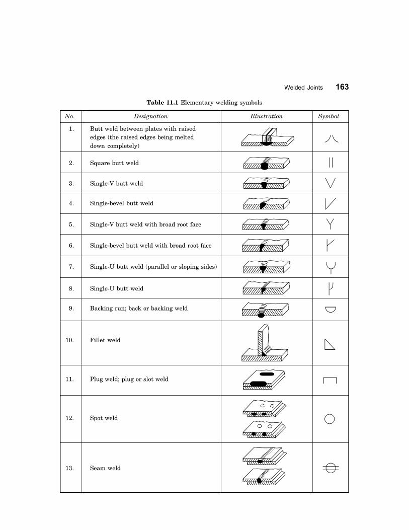
Table 11.1 Elementary welding symbols
No. Designation Illustration Symbol
1. Butt weld between plates with raisededges (the raised edges being melteddown completely)
2. Square butt weld
3. Single-V butt weld
4. Single-bevel butt weld
5. Single-V butt weld with broad root face
6. Single-bevel butt weld with broad root face
7. Single-U butt weld (parallel or sloping sides)
8. Single-U butt weld
9. Backing run; back or backing weld
10. Fillet weld
11. Plug weld; plug or slot weld
12. Spot weld
13. Seam weld

Table 11.2 Supplementary welding symbols
Shape of weld surface Symbol
(a) Flat (usually finished flush)
(b) Convex
(c) Concave
Table 11.3 Combination of elementary and supplementary symbols
Designation Illustration Symbol
Flat (flush) single-V butt weld
Convex double-V butt weld
Concave fillet weld
Flat (flush) single-V butt weld with flat(flush) backing run
Table 11.4 Combination of elementary symbols (contd.)
No. Designation Representation Symbolization
symbol either or(For number
refer to IllustrationTable 11.1)
1. Squarebutt weld
welded fromboth sides
2�2
2.Single-Vbutt weld

No. Designation Representation Symbolization
symbol either or(For number
refer to IllustrationTable 11.1)
3. andbacking run
3�9
4. Double-Vbutt weld
(X weld)3�3
5. Doublebevel
butt weld
6. (K weld)4�4
7. Double-Ubutt weld
7�7
8. Fillet weld
and filletweld
9
10�10
Table 11.4 Combination of elementary symbols
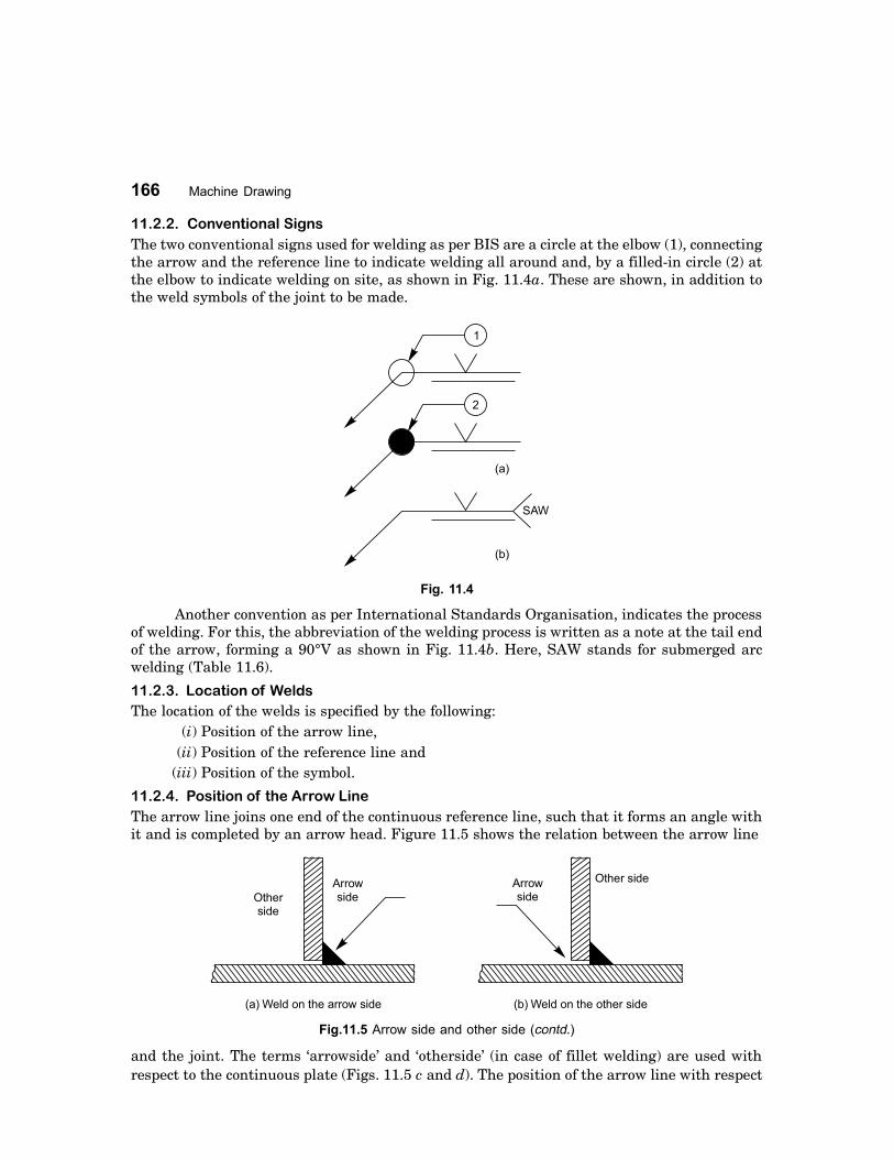
The two conventional signs used for welding as per BIS are a circle at the elbow (1), connectingthe arrow and the reference line to indicate welding all around and, by a filled-in circle (2) atthe elbow to indicate welding on site, as shown in Fig. 11.4a. These are shown, in addition tothe weld symbols of the joint to be made.
Another convention as per International Standards Organisation, indicates the processof welding. For this, the abbreviation of the welding process is written as a note at the tail endof the arrow, forming a 90°V as shown in Fig. 11.4b. Here, SAW stands for submerged arcwelding (Table 11.6).
The location of the welds is specified by the following:(i) Position of the arrow line,
(ii) Position of the reference line and(iii) Position of the symbol.
The arrow line joins one end of the continuous reference line, such that it forms an angle withit and is completed by an arrow head. Figure 11.5 shows the relation between the arrow line
and the joint. The terms �arrowside� and �otherside� (in case of fillet welding) are used withrespect to the continuous plate (Figs. 11.5 c and d). The position of the arrow line with respect

to the weld is generally of no special significance (Fig. 11.6). However, in the case of edgepreparation (Refer No. 4, 6 and 8 in Table 11.1), the arrow line points towards the plate whichis prepared (Fig. 11.7).
The reference line shall preferably be drawn parallel to bottom edge of the drawing and if it isnot possible; then it is drawn perpendicular.
The symbol is placed either above or beneath the reference line as per the following regu-lation:
It is placed on the continuous side of the reference line, if the weld (weld face) is on thearrow side of the joint or on the dashed line side, if the weld is on the other side of the joint, asshown in Fig. 11.8.
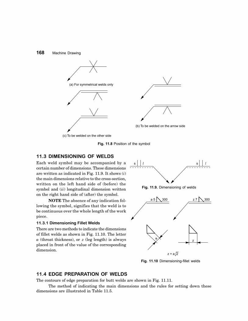
Each weld symbol may be accompanied by acertain number of dimensions. These dimensionsare written as indicated in Fig. 11.9. It shows (i)the main dimensions relative to the cross-section,written on the left hand side of (before) thesymbol and (ii) longitudinal dimension writtenon the right hand side of (after) the symbol.
NOTE The absence of any indication fol-lowing the symbol, signifies that the weld is tobe continuous over the whole length of the workpiece.
There are two methods to indicate the dimensionsof fillet welds as shown in Fig. 11.10. The lettera (throat thickness), or z (leg length) is alwaysplaced in front of the value of the correspondingdimension.
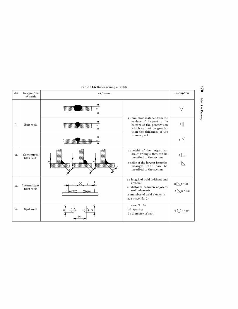
The contours of edge preparation for butt welds are shown in Fig. 11.11.The method of indicating the main dimensions and the rules for setting down these
dimensions are illustrated in Table 11.5.

Finishing of welds other than cleaning, shall be indicatedby suitable contour and finish symbols, viz., chipping C,machining M and grinding G. Where a weld is required tohave approximately flush surface without any othermethod of finishing, a straight line should be added belowthe symbol to indicate it (Fig. 11.12).
1. Symbols for fillet and similar welds should be shown, such that the vertical portion ofthe symbols are indicated on the left hand side of the symbol, irrespective of theorientation of the weld metal.
2. If the welds are to be made on the arrow side of a joint, the corresponding symbol shouldbe placed either above or below the cotinuous reference line (Fig. 11.8).
3. If the welds are to be made on the other side of a joint, the corresponding symbol shouldbe placed above or below the dashed reference line (Fig. 11.8).
4. If the welds are to the made on both sides of a joint, the corresponding symbols shouldbe placed on both sides of the reference line and the dashed line is not shown (Fig. 11.8).

5. The arrow of the symbol must point towards the joint which requires welding (Fig. 11.6).6. When only one member is to be edge prepared to make the joint, the arrow should point
at that plate (Fig. 11.7).7. Dimensions of size are indicated in mm without writting the unit mm. The letter a or z
is placed in front of the value of the fillet size, depending upon whether the throat or legand length of the weld is shown on the right hand side. If no length is given, it impliesthat full length is to be welded (Table 11.5).
8. If unequal legs of fillet are to be used, they should also be given on the left hand side.9. If a weld is to be made all around a joint, a circle should be placed at the elbow, connecting
the arrow to the reference line (Fig. 11.4 a).10. If a weld is required to be made on the site or during erection or assembly, it is represented
by a filled-in circle at the elbow, connecting the arrow and the reference line (Fig. 11.4 a)11. If a weld is to have a flush or flat finish, a straight line should be added above the
symbol.12. The welding process is indicated, if required, at the end of the arrow (Fig. 11.4 b).
In special cases, the technique of welding is indicated along with the welding symbol as aconvention. To avoid lengthy notes, the abbreviations (Table 11.6) are written as a note. Insome cases, code number is given with a foot note on the drawing near the title block.
The assembly drawing of a shaft support fabricated by welding is shown in Fig. 11.13 c, usingthe conventional weld symbols.
The drawing of the individual components (part drawings) with edge preparationwherever necessary, before they are joined by welding, are shown in Fig. 11.13 a. The isometricview of the assembly is shown in Fig. 11.13 b.
Table 11.6 Welding process designations
Designation Welding process Designation Welding process
CAW Carbon arc welding IB Induction brazingCW Cold welding IRB Infra red brazingDB Dip brazing OAW Oxy-acetylene weldingDFW Diffusion welding OHW Oxy-hydrogen weldingEBW Electron beam welding PGW Pressure gas weldingESW Electro slag welding RB Resistance brazingEXW Explosion welding RPW Projection weldingFB Furnace brazing RSEW Resistance seam weldingFOW Forge welding RSW Resistance spot weldingFRW Friction welding RW Resistance weldingFW Flash welding SAW Submerged arc weldingGMAW Gas metal arc welding TB Torch brazing
GTAW Gas tungsten arc welding UW Upset welding


THEORY QUESTIONS
11.1 What is welding and what type of fastesning is it?11.2 What are the advantages of welding over riveting?11.3 What are the materials that can be joined by welding?11.4 By what means, the location of a weld is specified?11.5 Categorise the welding symbols.11.6 How is a weld shown on the drawing?11.7 Explain the meaning of ��arrowside�� and ��other-side��, with reference to welded joints.11.8 Why the edges of various parts to be welded are prepared?11.9 What are the important rules to be observed while applying weld symbols?
11.10 Give the welding process abbreviations, for the following:(a) Explosion welding,(b) Electro-slag welding,(c) Forge welding, and(d) Oxy-acetylene welding.
11.11 Explain the following welding process symbols:(a) CAW (b) GMAW(c) GTAW (d) OAW(e) EBW (e) RW
DRAWING EXERCISES
11.1 Through sketches, indicate the various types of welding joints.11.2 Sketch and explain the two conventional signs used for welding as per BIS.11.3 Sketch the following welding symbols along with the respective illustrations:
(a) Single V-butt weld,(b) Single bevel butt weld,

(c) Single U-butt weld,(d) Single J-butt weld,(e) Fillet weld, and(f) Convex double V-butt weld.
11.4 Explain the meaning of each weld shown in Figs. 11.14 to 11.17 and sketch the part drawings.
11.5 Suggest suitable welding joints to fabricate the swing bracket shown in Fig. 11.18.11.6 Indicate appropriate welded joints shown by symbols to fabricate the structural joints shown in
Figs. 11.19 and 11.20.