National Pollutant Discharge eliminate System - Stanislaus ...
Upload
khangminh22Category
view
2download
0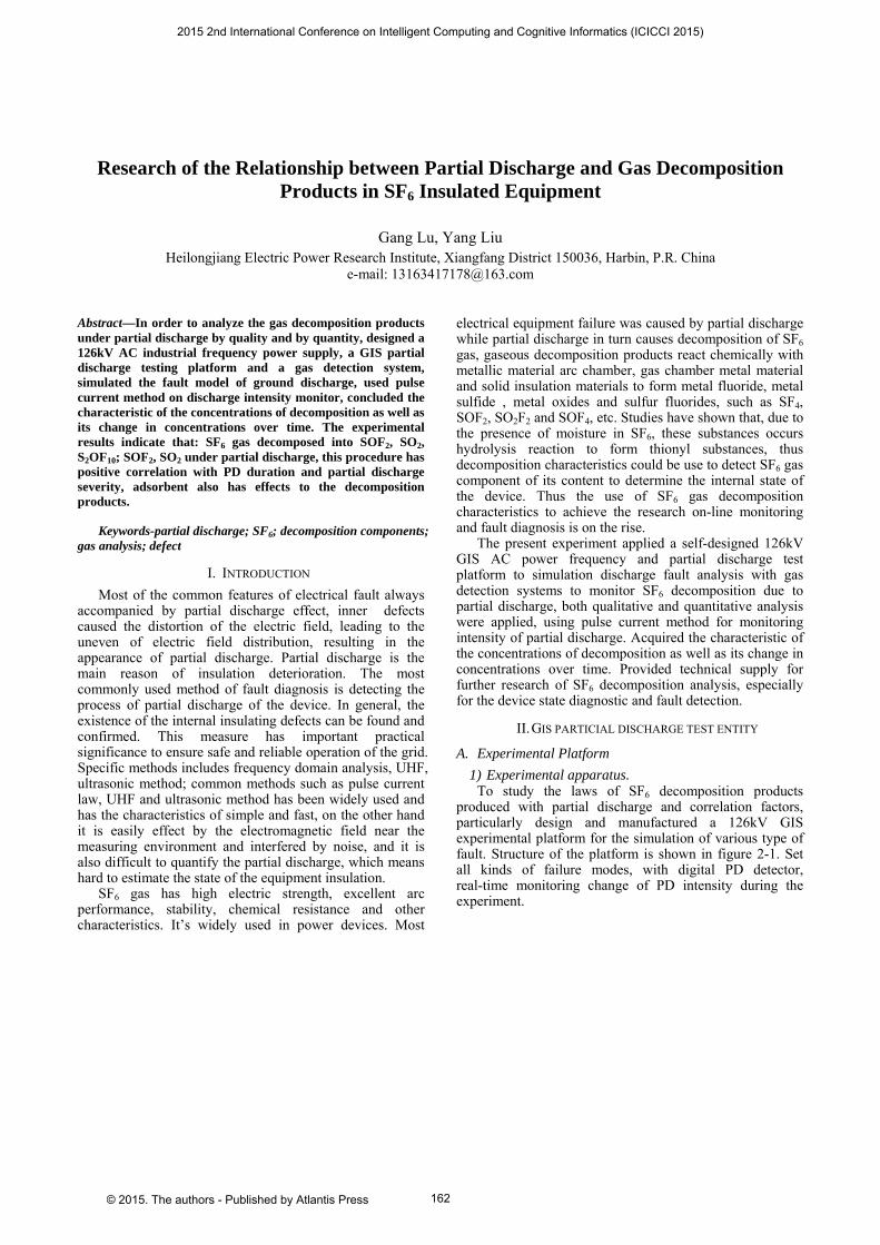
Research of the Relationship between Partial Discharge and Gas Decomposition Products in SF6 Insulated Equipment
Gang Lu, Yang Liu Heilongjiang Electric Power Research Institute, Xiangfang District 150036, Harbin, P.R. China
e-mail: [email protected]
Abstract—In order to analyze the gas decomposition products under partial discharge by quality and by quantity, designed a 126kV AC industrial frequency power supply, a GIS partial discharge testing platform and a gas detection system, simulated the fault model of ground discharge, used pulse current method on discharge intensity monitor, concluded the characteristic of the concentrations of decomposition as well as its change in concentrations over time. The experimental results indicate that: SF6 gas decomposed into SOF2, SO2, S2OF10; SOF2, SO2 under partial discharge, this procedure has positive correlation with PD duration and partial discharge severity, adsorbent also has effects to the decomposition products.
Keywords-partial discharge; SF6; decomposition components; gas analysis; defect
I. INTRODUCTION Most of the common features of electrical fault always
accompanied by partial discharge effect, inner defects caused the distortion of the electric field, leading to the uneven of electric field distribution, resulting in the appearance of partial discharge. Partial discharge is the main reason of insulation deterioration. The most commonly used method of fault diagnosis is detecting the process of partial discharge of the device. In general, the existence of the internal insulating defects can be found and confirmed. This measure has important practical significance to ensure safe and reliable operation of the grid. Specific methods includes frequency domain analysis, UHF, ultrasonic method; common methods such as pulse current law, UHF and ultrasonic method has been widely used and has the characteristics of simple and fast, on the other hand it is easily effect by the electromagnetic field near the measuring environment and interfered by noise, and it is also difficult to quantify the partial discharge, which means hard to estimate the state of the equipment insulation.
SF6 gas has high electric strength, excellent arc performance, stability, chemical resistance and other characteristics. It’s widely used in power devices. Most
electrical equipment failure was caused by partial discharge while partial discharge in turn causes decomposition of SF6 gas, gaseous decomposition products react chemically with metallic material arc chamber, gas chamber metal material and solid insulation materials to form metal fluoride, metal sulfide , metal oxides and sulfur fluorides, such as SF4, SOF2, SO2F2 and SOF4, etc. Studies have shown that, due to the presence of moisture in SF6, these substances occurs hydrolysis reaction to form thionyl substances, thus decomposition characteristics could be use to detect SF6 gas component of its content to determine the internal state of the device. Thus the use of SF6 gas decomposition characteristics to achieve the research on-line monitoring and fault diagnosis is on the rise.
The present experiment applied a self-designed 126kV GIS AC power frequency and partial discharge test platform to simulation discharge fault analysis with gas detection systems to monitor SF6 decomposition due to partial discharge, both qualitative and quantitative analysis were applied, using pulse current method for monitoring intensity of partial discharge. Acquired the characteristic of the concentrations of decomposition as well as its change in concentrations over time. Provided technical supply for further research of SF6 decomposition analysis, especially for the device state diagnostic and fault detection.
II. GIS PARTICIAL DISCHARGE TEST ENTITY
A. Experimental Platform 1) Experimental apparatus.
To study the laws of SF6 decomposition products produced with partial discharge and correlation factors, particularly design and manufactured a 126kV GIS experimental platform for the simulation of various type of fault. Structure of the platform is shown in figure 2-1. Set all kinds of failure modes, with digital PD detector, real-time monitoring change of PD intensity during the experiment.
2015 2nd International Conference on Intelligent Computing and Cognitive Informatics (ICICCI 2015)
© 2015. The authors - Published by Atlantis Press 162
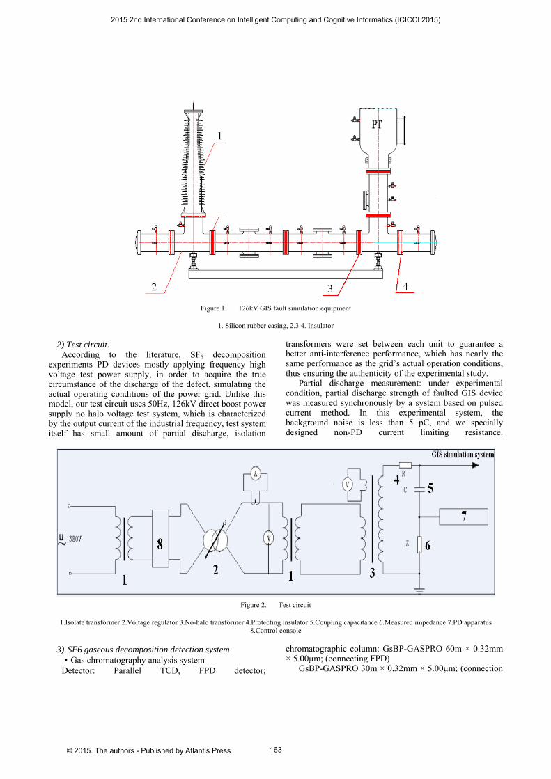
Figure 1. 126kV GIS fault simulation equipment
1. Silicon rubber casing, 2.3.4. Insulator
2) Test circuit. According to the literature, SF6 decomposition
experiments PD devices mostly applying frequency high voltage test power supply, in order to acquire the true circumstance of the discharge of the defect, simulating the actual operating conditions of the power grid. Unlike this model, our test circuit uses 50Hz, 126kV direct boost power supply no halo voltage test system, which is characterized by the output current of the industrial frequency, test system itself has small amount of partial discharge, isolation
transformers were set between each unit to guarantee a better anti-interference performance, which has nearly the same performance as the grid’s actual operation conditions, thus ensuring the authenticity of the experimental study.
Partial discharge measurement: under experimental condition, partial discharge strength of faulted GIS device was measured synchronously by a system based on pulsed current method. In this experimental system, the background noise is less than 5 pC, and we specially designed non-PD current limiting resistance.
Figure 2. Test circuit
1.Isolate transformer 2.Voltage regulator 3.No-halo transformer 4.Protecting insulator 5.Coupling capacitance 6.Measured impedance 7.PD apparatus 8.Control console
3) SF6 gaseous decomposition detection system ·Gas chromatography analysis system Detector: Parallel TCD, FPD detector;
chromatographic column: GsBP-GASPRO 60m × 0.32mm × 5.00μm; (connecting FPD)
GsBP-GASPRO 30m × 0.32mm × 5.00μm; (connection
2015 2nd International Conference on Intelligent Computing and Cognitive Informatics (ICICCI 2015)
© 2015. The authors - Published by Atlantis Press 163
TCD) Injection system: automatic injection valve, split
injection (both deactivated inert valves)
Figure 3. Process of gas chromatographic analysis
·Gas chromatography - mass spectrometry analysis
system Detector: MS; Column: GsBP-GASPRO 60m × 0.32mm × 5.00μm; Injection system: manual injection valve, split injection.
B. Experimental Procedure Setting bus-bar spikes on fault mode of GIS shell
discharge, pressure of SF6 was 0.42MPa, moisture content levels in equipment is within the scope of operating eligibility. Regulate the discharge voltage to achieve a stable partial discharge, continuous recording potential value and partial discharge; recording experimental time.
The gas sampling employing three ways: direct sampling, automatic sampling equipment and sampling cylinder. SF6 decomposition component was measured by gas chromatography and GC-MS, both analyses of qualitative and quantitative methods was applied in the course of the experiment. The interval of gas measurement sampling is 1 hour.
III. EXPERIMENTAL RESULTS
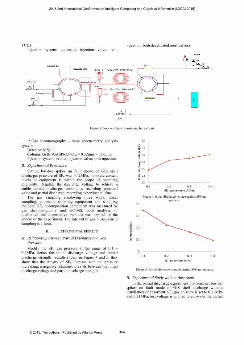
A. Relationship between Partial Discharge and Gas Pressure Modify the SF6 gas pressure at the range of 0.1 ~
0.4MPa, detect the initial discharge voltage and partial discharge strength,results shown in Figure 4 and 5, they show that the density of SF6 increase with the pressure increasing, a negative relationship exists between the initial discharge voltage and partial discharge strength.
Figure 4. Initial discharge voltage against SF6 gas
pressure
Figure 5. Partial discharge strength against SF6 gas pressure
B. Experimental Study without Adsorbent In the partial discharge experiment platform, set bus-bar
spikes on fault mode of GIS shell discharge without installation of absorbent. SF6 gas pressure is set to 0.11MPa and 0.21MPa, test voltage is applied to carry out the partial
2015 2nd International Conference on Intelligent Computing and Cognitive Informatics (ICICCI 2015)
© 2015. The authors - Published by Atlantis Press 164
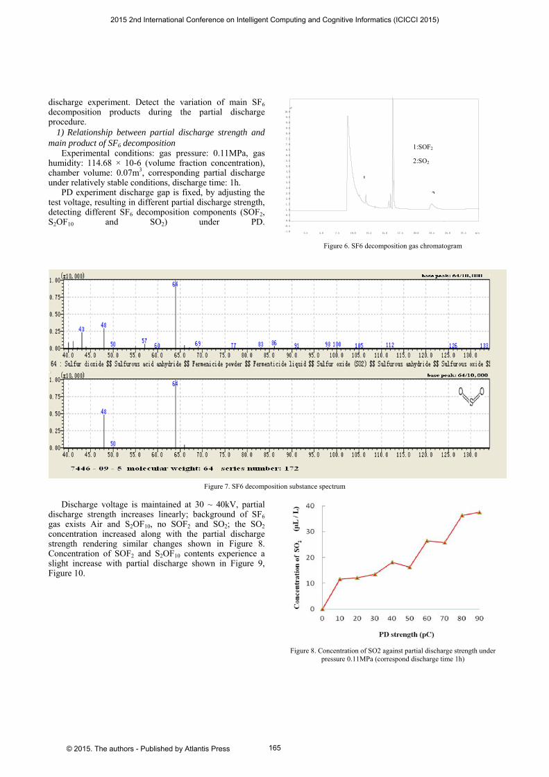
discharge experiment. Detect the variation of main SF6 decomposition products during the partial discharge procedure.
1) Relationship between partial discharge strength and main product of SF6 decomposition
Experimental conditions: gas pressure: 0.11MPa, gas humidity: 114.68 × 10⁻⁶ (volume fraction concentration), chamber volume: 0.07m3, corresponding partial discharge under relatively stable conditions, discharge time: 1h.
PD experiment discharge gap is fixed, by adjusting the test voltage, resulting in different partial discharge strength, detecting different SF6 decomposition components (SOF2, S2OF10 and SO2) under PD.
Figure 6. SF6 decomposition gas chromatogram
Figure 7. SF6 decomposition substance spectrum
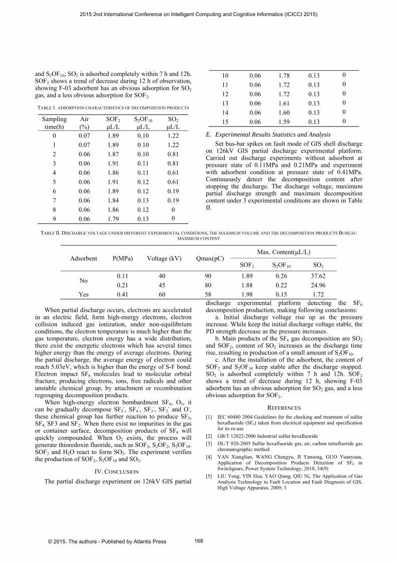
Discharge voltage is maintained at 30 ~ 40kV, partial discharge strength increases linearly; background of SF6 gas exists Air and S2OF10, no SOF2 and SO2; the SO2 concentration increased along with the partial discharge strength rendering similar changes shown in Figure 8. Concentration of SOF2 and S2OF10 contents experience a slight increase with partial discharge shown in Figure 9, Figure 10.
Figure 8. Concentration of SO2 against partial discharge strength under
pressure 0.11MPa (correspond discharge time 1h)
2.5 5.0 7.5 10.0 12.5 15.0 17.5 20.0 22.5 25.0 27.5 min-1.0
-0.5
0.0
0.5
1.0
1.5
2.0
2.5
3.0
3.5
4.0
4.5
5.0
5.5
6.0
6.5
7.0
7.5
8.0
8.5
9.0
9.5
10.0
uV
1
2
1:SOF2
2:SO2
2015 2nd International Conference on Intelligent Computing and Cognitive Informatics (ICICCI 2015)
© 2015. The authors - Published by Atlantis Press 165

Figure 9. Concentration of SOF2 against partial discharge strength under
pressure 0.11MPa (correspond discharge time 1h)
According to Figure 8 and 9, the result shows that partial discharge experiment production SOF2 is 1.59 ~ 1.89μL/L, augment with the increase of partial discharge strength. The content has greater augmentation in the initial experiments, as partial discharge continue the upward trend is slowed; relationship between S2OF10 and partial discharge strength appear to be the same trend with SOF2. As the partial discharge strength augments, the production slightly increase by 0.1μL / L; by analysis the relationship between partial discharge strength and the concentration of SO2, the results show that large amount of SO2 is produced during the partial discharge experiment, these increases shows a linear growth trend, the range of concentration remains within 11.55 ~ 37.62μL / L. In conclusion, the main production is SO2 and less SOF2.
Figure 10. Concentration of S2O2F10 against partial discharge strength
under pressure 0.11MPa (correspond discharge time 1h)
2) Relationship between discharge time and main product of SF6 decomposition.
Experimental conditions: gas pressure is 0.21MPa, gas humidity: 175.72 × 10⁻⁶ (volume fraction concentration) chamber volumes: 0.07m3, corresponding partial discharge under relatively stable conditions, discharge time: 8h.
The pressure level in the gas chamber remains
constantly at 0.21MPa, PD experiment discharge gap is fixed, by adjusting the test voltage, resulting in different partial discharge strength, detect different SF6 decomposition (SOF2、S2OF10 and SO2) components under PD condition.
As the discharge starts, the discharge voltage (44.7 ~ 46.8kV) remain stable, as the partial discharge strength (45 ~ 60pC) is relatively stable, Figure 11,12,13 show under the condition of the discharge voltage and partial discharge strength remains stable, the variation of concentration of SO2,SOF2 and S2OF10 as a function of voltage application time. The concentration of SOF2 and S2OF10 grows just as the result of prevent experiment shows, but the range of augmentation is larger. The Decomposition produce a great quantity of SO2, and the component of SO2 increase linearly with time.
Figure 11. Change in SO2 concentration as a function of voltage
application time at the pressure of 0.21MPa and PD strength of 45-60pC
Figure 12. Change in SOF2 concentration as a function of voltage
application time at the pressure of 0.21MPa and PD strength of 45-60pC
2015 2nd International Conference on Intelligent Computing and Cognitive Informatics (ICICCI 2015)
© 2015. The authors - Published by Atlantis Press 166
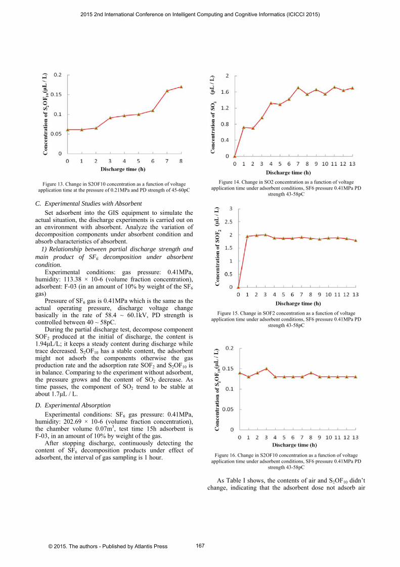
Figure 13. Change in S2OF10 concentration as a function of voltage application time at the pressure of 0.21MPa and PD strength of 45-60pC
C. Experimental Studies with Absorbent Set adsorbent into the GIS equipment to simulate the
actual situation, the discharge experiments is carried out on an environment with absorbent. Analyze the variation of decomposition components under absorbent condition and absorb characteristics of absorbent.
1) Relationship between partial discharge strength and main product of SF6 decomposition under absorbent condition.
Experimental conditions: gas pressure: 0.41MPa, humidity: 113.38 × 10⁻⁶ (volume fraction concentration), adsorbent: F-03 (in an amount of 10% by weight of the SF6 gas)
Pressure of SF6 gas is 0.41MPa which is the same as the actual operating pressure, discharge voltage change basically in the rate of 58.4 ~ 60.1kV, PD strength is controlled between 40 ~ 58pC.
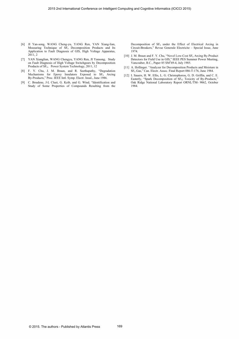
During the partial discharge test, decompose component SOF2 produced at the initial of discharge, the content is 1.94μL/L; it keeps a steady content during discharge while trace decreased. S2OF10 has a stable content, the adsorbent might not adsorb the components otherwise the gas production rate and the adsorption rate SOF2 and S2OF10 is in balance. Comparing to the experiment without adsorbent, the pressure grows and the content of SO2 decrease. As time passes, the component of SO2 trend to be stable at about 1.7μL / L.
D. Experimental Absorption Experimental conditions: SF6 gas pressure: 0.41MPa,
humidity: 202.69 × 10⁻⁶ (volume fraction concentration), the chamber volume 0.07m3, test time 15h adsorbent is F-03, in an amount of 10% by weight of the gas.
After stopping discharge, continuously detecting the content of SF6 decomposition products under effect of adsorbent, the interval of gas sampling is 1 hour.
Figure 14. Change in SO2 concentration as a function of voltage
application time under adsorbent conditions, SF6 pressure 0.41MPa PD strength 43-58pC
Figure 15. Change in SOF2 concentration as a function of voltage
application time under adsorbent conditions, SF6 pressure 0.41MPa PD strength 43-58pC
Figure 16. Change in S2OF10 concentration as a function of voltage
application time under adsorbent conditions, SF6 pressure 0.41MPa PD strength 43-58pC
As Table I shows, the contents of air and S2OF10 didn’t change, indicating that the adsorbent dose not adsorb air
2015 2nd International Conference on Intelligent Computing and Cognitive Informatics (ICICCI 2015)
© 2015. The authors - Published by Atlantis Press 167
and S2OF10; SO2 is adsorbed completely within 7 h and 12h. SOF2 shows a trend of decrease during 12 h of observation, showing F-03 adsorbent has an obvious adsorption for SO2 gas, and a less obvious adsorption for SOF2.
TABLE 1. ADSORPTION CHARACTERISTICS OF DECOMPOSITION PRODUCTS
Sampling time(h)
Air (%)
SOF2 μL/L
S2OF10 μL/L
SO2 μL/L
0 0.07 1.89 0.10 1.22 1 0.07 1.89 0.10 1.22 2 0.06 1.87 0.10 0.81 3 0.06 1.91 0.11 0.81 4 0.06 1.86 0.11 0.61 5 0.06 1.91 0.12 0.61 6 0.06 1.89 0.12 0.19 7 0.06 1.84 0.13 0.19 8 0.06 1.86 0.12 0 9 0.06 1.79 0.13 0
10 0.06 1.78 0.13 0 11 0.06 1.72 0.13 0 12 0.06 1.72 0.13 0 13 0.06 1.61 0.13 0 14 0.06 1.60 0.13 0 15 0.06 1.59 0.13 0
E. Experimental Results Statistics and Analysis Set bus-bar spikes on fault mode of GIS shell discharge
on 126kV GIS partial discharge experimental platform. Carried out discharge experiments without adsorbent at pressure state of 0.11MPa and 0.21MPa and experiment with adsorbent condition at pressure state of 0.41MPa. Continuously detect the decomposition content after stopping the discharge. The discharge voltage, maximum partial discharge strength and maximum decomposition content under 3 experimental conditions are shown in Table II.
TABLE II. DISCHARGE VOLTAGE UNDER DIFFERENT EXPERIMENTAL CONDITIONS, THE MAXIMUM VOLUME AND THE DECOMPOSITION PRODUCTS BUREAU MAXIMUM CONTENT
Adsorbent P(MPa) Voltage (kV) Qmax(pC) Max. Content(μL/L)
SOF2 S2OF10 SO2
No 0.11 40 90 1.89 0.26 37.62 0.21 45 80 1.88 0.22 24.96
Yes 0.41 60 58 1.98 0.15 1.72 When partial discharge occurs, electrons are accelerated
in an electric field, form high-energy electrons, electron collision induced gas ionization, under non-equilibrium conditions, the electron temperature is much higher than the gas temperature, electron energy has a wide distribution, there exist the energetic electrons which has several times higher energy than the energy of average electrons. During the partial discharge, the average energy of electron could reach 5.03eV, which is higher than the energy of S-F bond. Electron impact SF6 molecules lead to molecular orbital fracture, producing electrons, ions, free radicals and other unstable chemical group, by attachment or recombination regrouping decomposition products.
When high-energy electron bombardment SF6, O2, it can be gradually decompose SF5
-, SF4-, SF3
-, SF2- and O-,
these chemical group has further reaction to produce SF5, SF4, SF3 and SF2. When there exist no impurities in the gas or container surface, decomposition products of SF6 will quickly compounded. When O2 exists, the process will generate thioredoxin fluoride, such as SOF2, S2OF2, S2OF10. SOF2 and H2O react to form SO2. The experiment verifies the production of SOF2, S2OF10 and SO2.
IV. CONCLUSION The partial discharge experiment on 126kV GIS partial
discharge experimental platform detecting the SF6 decomposition production, making following conclusions:
a. Initial discharge voltage rise up as the pressure increase. While keep the initial discharge voltage stable, the PD strength decrease as the pressure increases.
b. Main products of the SF6 gas decomposition are SO2 and SOF2, content of SO2 increases as the discharge time rise, resulting in production of a small amount of S2OF10.
c. After the installation of the adsorbent, the content of SOF2 and S2OF10 keep stable after the discharge stopped. SO2 is adsorbed completely within 7 h and 12h. SOF2 shows a trend of decrease during 12 h, showing F-03 adsorbent has an obvious adsorption for SO2 gas, and a less obvious adsorption for SOF2.
REFERENCES [1] IEC 60480 2004 Guidelines for the checking and treatment of sulfur
hexafluoride (SF6) taken from electrical equipment and specification for its re-use
[2] GB/T 12022-2006 Industrial sulfur hexafluoride [3] DL/T 920-2005 Sulfur hexafluoride gas, air, carbon tetrafluoride gas
chromatographic method [4] YAN Xianglian, WANG Chengyu, JI Yansong, GUO Yuanyuan,
Application of Decomposition Products Detection of SF6 in Switchgears, Power System Technology, 2010, 34(9)
[5] LIU Yong, YIN Hua, YAO Qiang, QIU Ni, The Application of Gas Analysis Technology to Fault Location and Fault Diagnosis of GIS, High Voltage Apparatus, 2009, 3
2015 2nd International Conference on Intelligent Computing and Cognitive Informatics (ICICCI 2015)
© 2015. The authors - Published by Atlantis Press 168
[6] JI Yan-song, WANG Cheng-yu, YANG Ren, YAN Xiang-lian, Measuring Technique of SF6 Decomposition Products and Its Application to Fault Diagnosis of GIS, High Voltage Apparatus, 2011, 2
[7] YAN Xianglian, WANG Chengyu, YANG Ren, JI Yansong,Study on Fault Diagnosis of High Voltage Switchgears by Decomposition Products of SF6,Power System Technology, 2011, 12
[8] F. Y. Chu, J. M. Braun, and R. Seethapathy, “Degradation Mechanisms for Epoxy Insulators Exposed to SF6 Arcing By-Products,” Proc. IEEE Intl. Symp. Electr. Insul., June 1986.
[9] C. Boudene, J-L Cluet, G. Keib, and G. Wind, “Identification and Study of Some Properties of Compounds Resulting from the
Decomposition of SF6 under the Effect of Electrical Arcing in Circuit-Breakers,” Revue Generale Electricite – Special Issue, June 1974.
[10] J. M. Braun and F. Y. Chu, “Novel Low-Cost SF6 Arcing By-Product Detectors for Field Use in GIS,” IEEE PES Summer Power Meeting, Vancouber, B.C., Paper 85 SM369-4, July 1985.
[11] A. Hollinger. “Analyzer for Decomposition Products and Moisture in SF6 Gas,” Can. Electr. Assoc. Final Report 086-T-176, June 1984.
[12] I. Sauers, H. W. Ellis, L. G. Christophorou, G. D. Griffin, and C. E. Easterly, “Spark Decomposition of SF6; Toxicity of By-Products,” Oak Ridge National Laboratory Report ORNL/TM- 9062, October 1984.
2015 2nd International Conference on Intelligent Computing and Cognitive Informatics (ICICCI 2015)
© 2015. The authors - Published by Atlantis Press 169
Copyright © 2022 FDOKUMEN