Repair Parts Sheet - E-Series Electric Torque Wrench Pump
32
E-Series Electric Torque Wrench Pump Document Number Document Revision Document Revision Date Product Date Code Beginning With L4350 B 10/2019 A Repair Parts Sheet To Protect Your Warranty, Use Only ENERPAC Hydraulic Oil. Enerpac recommends that all kit components be installed to ensure optimum performance of the repaired product. Fully relieve hydraulic pressure, disconnect hydraulic hoses and unplug AC power cord from electrical outlet before beginning any inspection, maintenance or repair procedures. Failure to observe these precautions could result in death or serious personal injury. Appropriate shop safety procedures are to be followed during disassembly and reassembly to minimize any possibility of injury. WARNING Models: • EP3504TB and EP3504TB-M (100-120 VAC - NEMA 5-15 plug) • EP3504TI and EP3504TI-M (200-250 VAC - NEMA 6-15 plug) • EP3504TE and EP3504TE-M (200-250 VAC - Schuko CEE 7/7 plug)
-
Upload
khangminh22 -
Category
Documents
-
view
0 -
download
0
Transcript of Repair Parts Sheet - E-Series Electric Torque Wrench Pump

E-SeriesElectric Torque Wrench Pump
Document Number
Document Revision
Document Revision Date
Product Date Code Beginning With
L4350 B 10/2019 A
Repair Parts Sheet
To Protect Your Warranty, Use Only ENERPAC Hydraulic Oil.Enerpac recommends that all kit components be installed to ensure optimum performance of the repaired product.
Fully relieve hydraulic pressure, disconnect hydraulic hoses and unplug AC power cord from electricaloutlet before beginning any inspection, maintenance or repair procedures. Failure to observe these
precautions could result in death or serious personal injury. Appropriate shop safety procedures are to be followed during disassembly and reassembly to minimize any possibility of injury.
WARNING
Models:
• EP3504TB and EP3504TB-M (100-120 VAC - NEMA 5-15 plug)
• EP3504TI and EP3504TI-M (200-250 VAC - NEMA 6-15 plug)
• EP3504TE and EP3504TE-M (200-250 VAC - Schuko CEE 7/7 plug)

Figure 1, E-Series Torque Wrench Pump Main View �������������������������������������������������������������������������������������������������������3
Figure 1A, DC Power Cable Assembly ����������������������������������������������������������������������������������������������������������������������������4
Figure 1B, Serial Communications Cable Assembly ������������������������������������������������������������������������������������������������������4
Figure 1C, Jumper Connection ��������������������������������������������������������������������������������������������������������������������������������������5
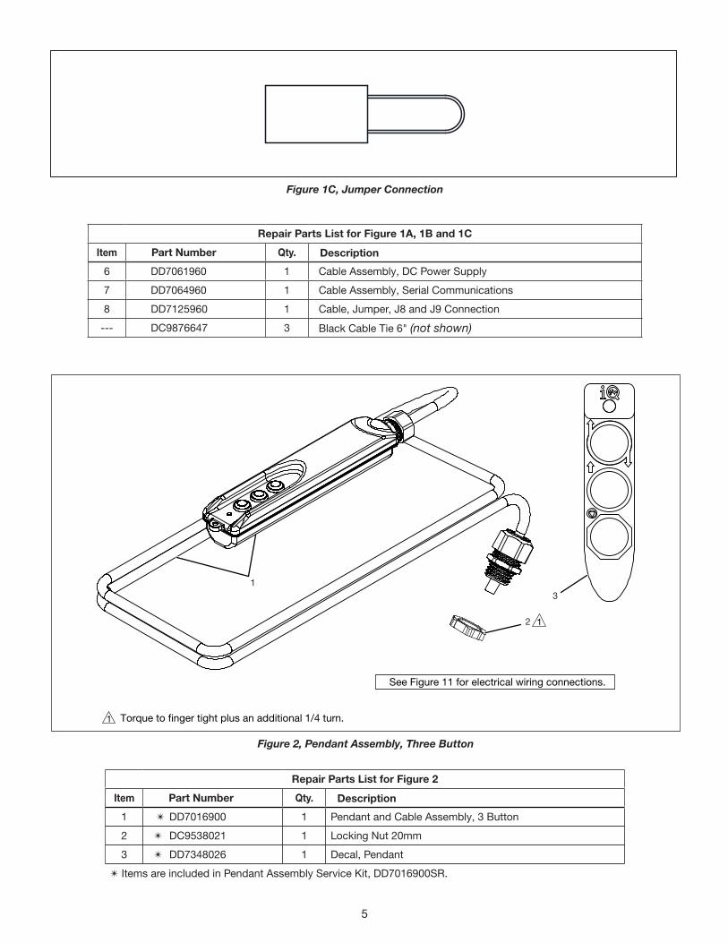
Figure 2, Pendant Assembly ��������������������������������������������������������������������������������������������������������������������������������������������5
Figure 3, Power App Board Assembly ����������������������������������������������������������������������������������������������������������������������������6
Figure 4, Motor Controller Assembly �������������������������������������������������������������������������������������������������������������������������������7
Figure 5, Pump/Motor Assembly �������������������������������������������������������������������������������������������������������������������������������������8
Figure 5A, Motor Replacement Kit ��������������������������������������������������������������������������������������������������������������������������������10
Figure 6, Motor Replacement Kit ����������������������������������������������������������������������������������������������������������������������������������11
Figure 6A, Eccentric Kit �������������������������������������������������������������������������������������������������������������������������������������������������12
Figure 6B, Pump Housing Kit ����������������������������������������������������������������������������������������������������������������������������������������13
Figure 6C, Piston Block Assembly Kits �������������������������������������������������������������������������������������������������������������������������14
Figure 6D, Piston Block Seal Kit ������������������������������������������������������������������������������������������������������������������������������������15
Figure 6E, Intake Suction Filter Kit ��������������������������������������������������������������������������������������������������������������������������������15
Figure 7, Major Components, Control Valve and Pump ������������������������������������������������������������������������������������������������16
Figure 7A, Control Valve Mounting Hardware and Hydraulic Connections �������������������������������������������������������������������17
Figure 7B, Valve Assembly ��������������������������������������������������������������������������������������������������������������������������������������������18
Figure 7C, Direct Drive Pump Assembly �����������������������������������������������������������������������������������������������������������������������19
Figure 7D, Rebuild Kit, User-Adjustable Relief Valve (UARV) ����������������������������������������������������������������������������������������20
Figure 7E, Heat Exchanger Assembly ���������������������������������������������������������������������������������������������������������������������������21
Figure 8, Reservoir Assembly ����������������������������������������������������������������������������������������������������������������������������������������22
Figure 9, Front End Cap Assembly ��������������������������������������������������������������������������������������������������������������������������������23
Figure 10, Rear End Cap Assembly ������������������������������������������������������������������������������������������������������������������������������24
Figure 10A, Power Cord Replacement Kit ���������������������������������������������������������������������������������������������������������������������25
Figure 11, Electrical Block Wiring Diagram �������������������������������������������������������������������������������������������������������������������26
Figure 12, Hydraulic Schematic ������������������������������������������������������������������������������������������������������������������������������������27
Figure 13, Pump Cover Removal/Installation Instructions ��������������������������������������������������������������������������������������������28
Table of Contents: Page
Notes:• Parts lists indicate the total quantity of each part used in a figure�• The quantity of a part supplied in a repair kit or service assembly may be less than the total quantity shown in the
parts list�• Information contained in this document is subject to change without notice due to design variables, product
improvements and other factors� Copyright © 2019 Enerpac� All rights reserved�

1
2
4
15
14
13
16
12
8
7
6
4
3
2
1
1
2
3
4
Torque to 42-47 in-lbs [4�8-5�3 Nm]�
Torque to finger tight plus an additional 1/4 turn�
Apply NPTF tape, torque to 28-34 ft-lbs [38-46 Nm]�
Torque to 13-16 ft-lbs [18-22 Nm]�
Figure 1, E-Series Torque Wrench Pump - Main View
3

Repair Parts List for Figure 1
Item Part Number Qty. Description1 Y CAE1050108-1A 2 Flat Washer
2 Y CCE523028-1A 2 Screw-SHCS, Hex
3 CF773900 1 Half Coupler, Hose End
4 DC9538021 1 Locking Nut 20mm
5 DC9876647 3 Black Cable Tie 6"
6 Y DD6789800 1 Pump Handle
7 DD6988223 1 Pressure Gauge
8 see Figure 2 1 Pendant Assembly
9 DD7061960 1 DC Power Supply Cable Assembly
10 DD7064960 1 Serial Communications Cable Assembly
11 DD7125960 2 J8 and J9 Connection Cable Jumper
12 Y DD7167026 1 Troubleshooting Decal
13 see Figure 9 1 Front End Cap Assembly
14 see Figure 3 1 Power App Board Assembly
15 see Figure 4 1 Motor Controller Assembly
16 DD7557006 1 Plug, SAE #8, Zero-Leak
Y Items are included in Pump Handle Service Kit, DD5789800SR�
V+
V-
Red
Black
Red
BlackJ2 Connector
2J2
A
A Section A-A
112
Serial Communication PortBlack 1Red 2
White 3J6
Black 3Red 2
White 1
A
A
Section A-A
B
B
Section B-B
123 1 2 3
Figure 1A, DC Power Cable Assembly
Figure 1B, Serial Communications Cable Assembly
4
1
2
3
See Figure 11 for electrical wiring connections.
Torque to finger tight plus an additional 1/4 turn.1
1
Figure 2, Pendant Assembly, Three Button
Repair Parts List for Figure 1A, 1B and 1C
Item Part Number Qty. Description
6 DD7061960 1 Cable Assembly, DC Power Supply
7 DD7064960 1 Cable Assembly, Serial Communications
8 DD7125960 1 Cable, Jumper, J8 and J9 Connection
--- DC9876647 3 Black Cable Tie 6" (not shown)
Repair Parts List for Figure 2
Item Part Number Qty. Description
1 T DD7016900 1 Pendant and Cable Assembly, 3 Button
2 T DC9538021 1 Locking Nut 20mm
3 T DD7348026 1 Decal, Pendant
T Items are included in Pendant Assembly Service Kit, DD7016900SR�
Figure 1C, Jumper Connection
5

1
2
3
4
1 23
2
4 11 211112
10
9
8
7
6
54 32 1
See Figure 11for DIP switchsettings.
Repair Parts List for Figure 3
Item Part Number Qty. Description
1 BF1607027AX 2 Set Screw
2 CBE411028-1A 3 Hex Screw
3 CCE1040108-7A 2 Lock Washer
4 DC9876647 3 6" Cable Tie
5 DD6792098-P03 1 Cover
6 J DD7298900 1 Power Board Assembly
7 DD7326217 3 Cable Tie
8 DD7448037 1 Lip Seal
9 X DD7462037 2 Gasket
10 J DD7513001 2 Thread Forming Screw
11 DD7516122 2 Hex Nut
12 DD7609111 1 Bracket, Motor Controller Restraint
X Item is included in Water Ingress Seal Service Kit, EPWISK�J Items are included in Power App Board Assembly Service Kit, DD7298900K�
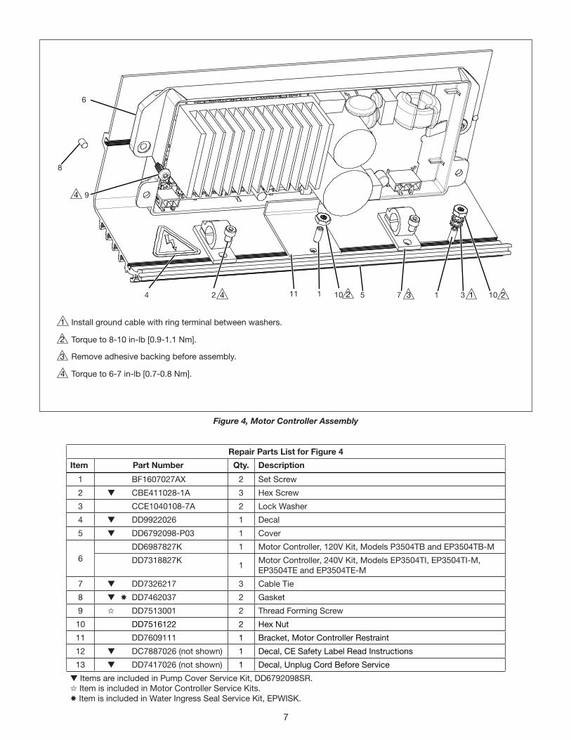
Install ground cable with ring terminal between washers�
Torque to 8-10 in-lb [0�9-1�1 Nm]�
Remove adhesive backing before assembly�
Torque to 6-7 in-lb [0�7-0�8 Nm]�
Figure 3, Power App Board Assembly
6
1
1
2
2
3
3
4
4
4
4
9
8
6
2 5 7 1 3 10210111
Repair Parts List for Figure 4
Item Part Number Qty. Description
1 BF1607027AX 2 Set Screw
2 t CBE411028-1A 3 Hex Screw
3 CCE1040108-7A 2 Lock Washer
4 t DD9922026 1 Decal
5 t DD6792098-P03 1 Cover
6 DD6987827K 1 Motor Controller, 120V Kit, Models P3504TB and EP3504TB-M
DD7318827K 1 Motor Controller, 240V Kit, Models EP3504TI, EP3504TI-M, EP3504TE and EP3504TE-M
7 t DD7326217 3 Cable Tie
8 t X DD7462037 2 Gasket
9 I DD7513001 2 Thread Forming Screw
10 DD7516122 2 Hex Nut
11 DD7609111 1 Bracket, Motor Controller Restraint
12 t DC7887026 (not shown) 1 Decal, CE Safety Label Read Instructions
13 t DD7417026 (not shown) 1 Decal, Unplug Cord Before Service
t Items are included in Pump Cover Service Kit, DD6792098SR�I Item is included in Motor Controller Service Kits�X Item is included in Water Ingress Seal Service Kit, EPWISK�
Install ground cable with ring terminal between washers�
Torque to 8-10 in-lb [0�9-1�1 Nm]�
Remove adhesive backing before assembly�
Torque to 6-7 in-lb [0�7-0�8 Nm]�
Figure 4, Motor Controller Assembly
7
1
2
3
4
5
6
78
8
1
1
5
23
3
3
4
6
6
6
727
26
25
24
23
22
21
2019
1817
8
28 1722
16
15
13
11
10
9
87 65
4
4
3
2
1
Align notch incounterweight
with keyholein shaft.
Insert tubes and torque to 150-160 in-lb [203-217 Nm] (At manifold end prior to installing pump into reservoir)�Apply Loctite 243�
Torque to 42-47 in-lb [4�7-5�3 Nm]�
Bend tube vertical while install pump into reservoir�Align mark on counterweight with drill point and key slot on shaft (see Detail C)�Torque to 32-39 ft-lbs [43-53 Nm]�
Torque to 100-120 ft-lbs [43-53 Nm]�
Items pre-assembled�
Orient ferrule for compression fittingwith small end OD toward tube end�
(See Detail A and Detail B)
DETAIL C
DETAIL A
DETAIL B
Figure 5, Pump/Motor Assembly8
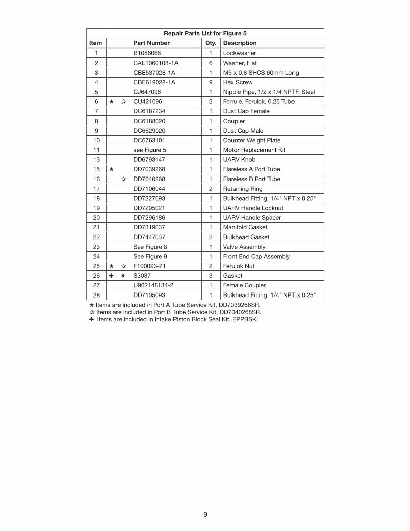
Repair Parts List for Figure 5
Item Part Number Qty. Description
1 B1086066 1 Lockwasher
2 CAE1060108-1A 6 Washer, Flat
3 CBE537028-1A 1 M5 x 0�8 SHCS 60mm Long
4 CBE619028-1A 9 Hex Screw
5 CJ647096 1 Nipple Pipe, 1/2 x 1/4 NPTF, Steel
6 H P CU421096 2 Ferrule, Ferulok, 0�25 Tube
7 DC6187234 1 Dust Cap Female
8 DC6188020 1 Coupler
9 DC6629020 1 Dust Cap Male
10 DC6763101 1 Counter Weight Plate
11 see Figure 5 1 Motor Replacement Kit
13 DD6793147 1 UARV Knob
15 H DD7039268 1 Flareless A Port Tube
16 P DD7040268 1 Flareless B Port Tube
17 DD7106044 2 Retaining Ring
18 DD7227093 1 Bulkhead Fitting, 1/4" NPT x 0�25"
19 DD7295021 1 UARV Handle Locknut
20 DD7296186 1 UARV Handle Spacer
21 DD7319037 1 Manifold Gasket
22 DD7447037 2 Bulkhead Gasket
23 See Figure 8 1 Valve Assembly
24 See Figure 9 1 Front End Cap Assembly
25 H P F100093-21 2 Ferulok Nut
26 : W S3037 3 Gasket
27 U962148134-2 1 Female Coupler
28 DD7105093 1 Bulkhead Fitting, 1/4" NPT x 0�25"
H Items are included in Port A Tube Service Kit, DD7039268SR�P Items are included in Port B Tube Service Kit, DD7040268SR�: Items are included in Intake Piston Block Seal Kit, EPPBSK�
9

Repair Parts List for Figure 5A
Item Part Number Qty. Description
1 DD6770259 1 Motor Stator Assembly
2 DD6771257 1 Motor Rotor
3 DD7003021 1 Nut, Flange M10 x 1�25, with Counterbore
Note: Motor Replacement Kit DD6770259K includes all items listed in the table above�
1
2
3
Apply Loctite 243.
Torque to 42-47 in-lbs [56.9-63.7 Nm].
Torque to 100-120 in-lbs [11-14 Nm]. See Figure 11 for electrical wiring connections.
2
3
23
6
6
Figure 5A, Motor Replacement Kit
10

6
10
See Figure 6C
VIEW A - Drain Hole Alignment See Figure 6A
See Figures 7 through 7E
See Figure 6D(item 6)
See Figure 6B
See Figure 6D(item 5)
See Figure 6E
13
9
15
Apply grease to aid assy of housing to manifold.
Torque to 7-9 ft-lbs [9.4-12.2 Nm].
Apply Loctite 2760, and torque to 55-65 in-lbs [6.2-7.3 Nm].
Install flush with top surface, after adding oil.
Orient as shown.
Manifold(viewed from underside)
Drain Holes
Housing
IMPORTANT: As parts are assembled, align drain hole in housing with drain hole on manifold.
1
1
2
2
4
4
5
5
7
7
Figure 6, Motor Replacement Kit
11

Figure 6A, Eccentric Kit
12
Repair Parts List for Figure 6
Item Part Number Qty. Description
3 B1314503 1 O-Ring-1/4", 7/16", NBR, 70 Duro
6 CAE1060055-1A 12 Acorn Nut M6
9 CCA1042044-1C 1 Wiper Ring
10 CCA627028-5A 12 Screw-Set, Flat, HS, M6 x 1 x 35, 45H, Plain
13 DD7004900 1 Shaft, Sub Assembly
15 DD7008476 1 Seal, Rotary 17 x 42 x 7
(Assembled View)
2
5
3
4
1
Eccentric (items 1-4) is shipped pre-assembled. Parts are shown disassembled for referencepurposes only. Item 1 is shipped loose with the eccentric assembly and attaches to thebottom of the motor shaft after the eccentric assembly is put on.
Press fit item 3 onto item 5 with 1100 psi on 10 ton press.
1
1
Repair Parts List for Figure 6AItem Part Number Qty. Description
1 CCA1018044-1A 1 Retaining Ring-Ext�, 18mm, STL
2 CCA1028044-1A 1 Retaining Ring-Ext�, 28mm, STL
3 DD6779350 1 Bearing, Sleeve, 28 x 32 x 15
4 DD7257537 1 Eccentric (3mm Offset)
5 DD7261350 1 Race, Cam
Note: Eccentric Kit DD72575375SR includes all items listed in the table above (pre-assembled)�

13
Assemble intocenter holeof pattern.
Flush
1
4
2 3
Press item 1 and 2 together flush as shown. 400 psi using 10 ton press.
Press using finger.
1
13
1
2
Lubricate with oil prior to assembly.3
2
Figure 6B, Pump Housing Kit
Repair Parts List for Figure 6B
Item Part Number Qty. Description
1 DD6762001 1 Housing, Pump
2 DD6775039 1 Bushing, 18 x 20 x 20, Housing
3 DD6965661 1 Inlet Check Umbrella Valve, Housing
4 DD7603101 1 Valve, Mini, Duckbill
Note: Pump Housing Kit DD7005900SR includes all items listed in the table above�

14
Piston(Ø 9mm or Ø 6mm)
Piston BlockO-Ring
(Fig. 6D, Item 3)
• Each piston block kit includes 1 piston block and 1 piston block O-Rings (Figure 6D, item 3).• It is recommended that new O-Rings be installed on ALL piston blocks, even if only some of the piston blocks are being replaced. • A complete set of O-Rings and gaskets is provided in the piston block seal kit (order separately - See Figure 6D).• Refer to Figures 6, 6A, 6B and 6D for torque values and additional assembly instructions.
(Pump manifold viewed from below)
Manifold
Housing
Ø 9mm
Ø 9mm Ø 9mm
Ø 6mm
Ø 6mm Ø 6mm
Oil Drain Hole Side with oil port must face toward manifold.
Flat side must face toward housing.
IMPORTANT:
2
1
1
1
2
2
Figure 6C, Piston Block Assembly Kits
Repair Parts List for Figure 6C
Item Part Number Qty. Description
1 DD7230900SR 3 Piston Block, Ø 6mm
2 DD7231900SR 3 Piston Block, Ø 9mm

15
5
4
1
3
5
2See Figure 6Efor location
See Figure 6for locations
See Figure 6Cfor locations
See Figure 6for location
See Figure 5 (item 26)for locations.
Drain Hole
This kit does not contain manifold gasket DD7319037. Order separately if needed. See Figure 5, item 21.
13
4
2
CLAMP
Figure 6D, Piston Block Seal Kit
Figure 6E, Intake Suction Filter Kit
Repair Parts List for Figure 6D
Item Part Number Qty. Description
1 B1400503 1 O-Ring 4-1/4", 4-3/8", 1/16", NBR, 70 Duro
2 DD7002646 1 Hose Rubber, 9�52 x 15�88 x 50L
3 DD7616903 6 O-Ring, Piston Block, Metric, 8 x 2, NBR, 90 Duro
4 DD7603101 1 Valve Mini, Cross-Slit
5 S3037 12 Gasket
Note: Piston Block Seal Kit EPPBSK includes all items listed in the table above�
Repair Parts List for Figure 6E
Item Part Number Qty. Description
1 DD7002646 1 Hose, Rubber, 9�52 x 15�88 x 50L
2 DD7176118 1 Filter, In Line
3 DD7177268 1 Tube, Inlet Filter
4 DD7222299 2 Clamp, Inlet Filter
Note: Intake Suction Filter Kit DD7176118K includes all items listed in the table above�

1, 2
6
4
5
3
16
Figure 7, Major Components, Control Valve and Pump
Repair Parts List for Figure 7
Item Part Number Qty. Description
1, 2 see Figure 7A and 7B 1 Control Valve and Mounting
3 see Figure 7D 1 Direct Drive Pump
4 see Figure 7E 1 User Adjustable Relief Valve
5 see Figure 7C 1 Heat Exchanger Assembly
6 see Figure 7C 1 Pressure Transducer

Repair Parts List for Figure 7A
Item Part Number Qty. Description
1 y B1005503 2 O-ring 1/4" x 3/8" x 1/16"
2 y B1009803 2 O-ring 7/32" x 11/32" x 1/16"
3 y B1010564 2 Back-up Ring
4 y B1227503 2 O-ring 15/16" x 1-1/16" x 1/16"
5 y CAA411016-2B 2 4mm x 8mm Dowel Pin
6 y CCA535028-1A 4 Screw, Hex, M5
7 y DD7033268 1 Tube, Connector, Spacer
y Items are included in Torque Wrench Valve Replacement Kit, EP5TWVSK�
7
6
5
5
4
4
3
2
2
1
1
3
1 2
33
3
4 5
1
2
3
4
5
3
View A731 3 1
see ‘View A’ for Assembly Order
Figure 7A, Control Valve Mounting Hardware and Hydraulic Connections
Apply Loctite 243�
Torque to 55-65 in-lb [6�2-7�3 Nm]�
Assembly order critical: Install back-up ring first, then O-Ring�
Torque to vertical orientation� 28 ft-lb [40 Nm] minimum�
Apply Teflon tape to NPTF thread�
17

23
Section B-B
Section A-A
22
BA
AB
20
17
16 13
8
43
1716
13
4
3
8
20
23
22
14
3
3 9 10
9
10
4
9 4
4
9 5
5
9 4
Set B Side relief to 2,500-2,700 psi [172-186 bar].
Torque to 55-65 ft-lbs [6.2-7.3 Nm].
Torque to 20-22 ft-lbs [27.1-29.8 Nm].
Apply Loctite 243.
Torque to 90-100 ft-lbs [10.17-11.30 Nm].
Figure 7B, Valve Assembly
Repair Parts List for Figure 7B
Item Part Number Qty. Description
3 D B1003503 1 O-ring
4 D B1005016 1 Ball 3/16"
8 D C846037 1 Copper Gasket
13 D DD4790051 1 Piston, B-Side Pilot
14 DD5655660SR 1 Valve 3-Way 2-Position
16 D DD6330141 1 Piston O-ring
17 D DD6331141 1 Piston Slipper
20 D DD7232314 1 Zinc Plated Steel Sealing Washer
22 D DD7363110 1 Spring
23 D P20037 1 Gasket, Valve Plug
D Items are included in 4-2 Torque Wrench Valve Rebuild Kit And Hawe Replacement Kit, EP5TWVSR�
See Wiring Diagram (Figure 11)
18
Torque to 13-16 ft-lbs [18-22 Nm].
Press into manifold 500 psi on 10 ton press. Coin 300 psi on 10 ton press after assembly.
Observe direction.
Press fit 1100 psi on 10 ton press.
Torque to 28-34 ft-lbs [38-46 Nm].
Torque to orientation 16 ft-lbs [22 Nm] min.
Torque to 6-8 ft-lbs [8-11 Nm].
Torque to vertical orientation, 28 ft-lb [40 Nm] min.
Apply Teflon tape to NPTF thread.
Coin 150 psi on 10 ton press.
Lubricate O-Ring.
Torque to 8-10 ft-lbs [10.8-13.6 Nm].
Torque to below flush, min 7 ft-lbs [9.5 Nm].
Torque 9-11 ft-lbs [12-15 Nm] .
3
4
5
6
7
8
9
10
11
12
13
14
15
16
15
101111
9
9
8
9
9
3
14
16 95
4
6
7
11
16
7 18
13 223
7
17
20
11
13
11 1
1317
9
13
13
12
15
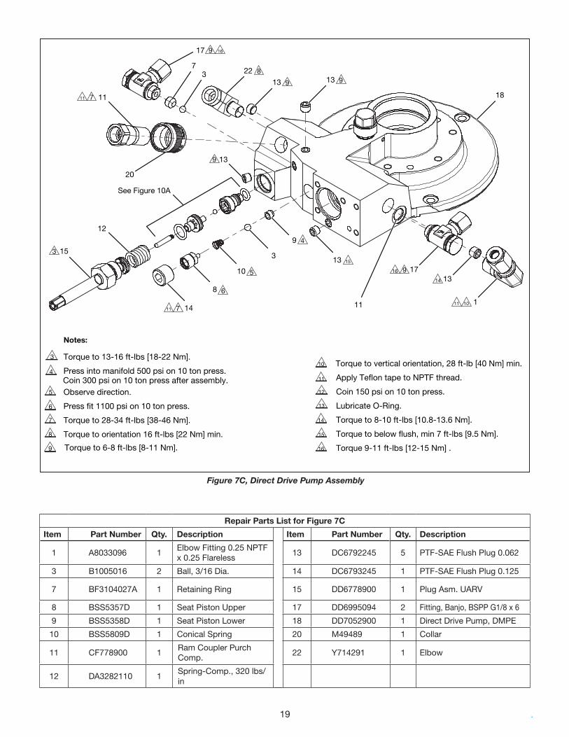
Notes:
3
14
8
10
See Figure 10A
Figure 7C, Direct Drive Pump Assembly
Repair Parts List for Figure 7C
Item Part Number Qty. Description Item Part Number Qty. Description
1 A8033096 1 Elbow Fitting 0�25 NPTF x 0�25 Flareless 13 DC6792245 5 PTF-SAE Flush Plug 0�062
3 B1005016 2 Ball, 3/16 Dia� 14 DC6793245 1 PTF-SAE Flush Plug 0�125
7 BF3104027A 1 Retaining Ring 15 DD6778900 1 Plug Asm� UARV
8 BSS5357D 1 Seat Piston Upper 17 DD6995094 2 Fitting, Banjo, BSPP G1/8 x 6
9 BSS5358D 1 Seat Piston Lower 18 DD7052900 1 Direct Drive Pump, DMPE
10 BSS5809D 1 Conical Spring 20 M49489 1 Collar
11 CF778900 1 Ram Coupler Purch Comp� 22 Y714291 1 Elbow
12 DA3282110 1Spring-Comp�, 320 lbs/in
19

Repair Parts List for Figure 7D
Item Part Number Qty. Description
1 B1003016 1 Ball, 0�125 Dia�
2 B1010803 1 O-Ring-1/4", 3/8", 1/16", Disogrin, 92 Duro
3 B1012203 1 O-Ring-3/8", 1/2", 1/16", Viton, 90 Duro
4 BA0210059 1 Dowel Pin 1/8" x 5/8" Long
5 DD6780013 1 Ball Guide
6 DD7234290 1 Ball Seat
7 PA27110 1 Spring-Comp�, 8�30 lbs/in
Note: UARV Rebuild Kit DD7234290K includes all items listed in the table above�
These parts not included in kit.Refer to Figure 10.
4
73
5
16
2
Torque to 84-108 in-lbs [9.5-12.2 Nm].
Press fit 150-200 psi on 10 ton press, Item 1 onto item 5.
Torque to 13-16 ft-lbs [18-22 Nm].
Coin 150 psi on 10 ton press.
1
2
3
3
4
1 42
Figure 7D, Rebuild Kit, User-Adjustable Relief Valve (UARV)
20

Repair Parts List for Figure 7E
Item Part Number Qty. Description
1 DD6995094 2 Banjo Fitting
2 DD26999471 1 Heat Exchange Fin Tube
3 BF3104027 1 Set Screw
4 B1005016 1 Ball 3/16"
Note: Heat Exchanger Kit DD6999471SR includes all items listed in the table above�
1 2
3
4 1
1
1
1
Figure 7E, Heat Exchanger Assembly
Torque to 6-8 ft-lbs [8-11 Nm]�
21

1
1
2
2
2
3
8
7 6
5
43
2
2
1
Torque to 60-70 in-lb [6�8-7�9 Nm]�
Torque to 106-133 in-lb [12-15 Nm]�
Figure 8, Reservoir Assembly
Repair Parts List for Figure 11
Item Part Number Qty. Description Item Part Number Qty. Description
1 CAE1060055-1A 2 Acorn Nut 5 j W DD7164108 2 Rubber Sealing Washer
2 CBE821028-1A 8 Hex Screw 6 W DD7290026 2 Decal
3 W DD6788025-P03 1 1 Gallon Reservoir 7 see Figure 9 1 Front End Cap Assembly
4 DD6795870 2 Rubber Foot 8 see Figure 10 1 Rear End Cap Assembly
W Items are included in Reservoir Sealing Kit, EPRSK�j Items are included in Reservoir Replacement Kit, DD6788025SR�
22

1
2
3
4
5
1
2
3
4
5
12
9
11
10
87
4
6
53
2
1
Repair Parts List for Figure 9
Item Part Number Qty. Description Item Part Number Qty. Description
1 v B1240503 1 O-ring 7 v DD7021223 1 Sight Gauge
2 v DD3883028 2 Screw 8 v DD7022225 1 Sight Gauge Insert
3 DD6784020 1 Front End Cap 9 X DD7030037 1 Gasket Tape
4 DD6796808 1 Gauge Grommet 10 DD7107305 2 Threaded Rod
5 DD7002646 2 Rubber Hose 11 DD7238001 1 Screw
6 j W DD70170371 1 Endcap Gasket 12 DD7331217 1 Cable Tie
v Items are included in Sight Glass Kit, DD7021223K�W Items are included in Reservoir Sealing Kit, EPRSK�j Items are included in Reservoir Replacement Kit, DD6788025SR�X Items are included in Water Ingress Seal Service Kit, EPWISK�
Apply Loctite 2760�
Torque to 8-10 in-lb [0�9-1�1 Nm]�
Remove adhesive backing before assembly�
Install to full depth�
Torque to 25-30 in-lb [2�8-3�4 Nm]�
Figure 9, Front End Cap Assembly
23

1112
10
9
8
7
6
5
4
32
1
1
1
2
2
4
3
5
4
6
6
5
Repair Parts List for Figure 10
Item Part Number Qty. Description Item Part Number Qty. Description
1 R CBA413028-1B 3 Hex Screw Flathead 8 X DD7030037 1 Gasket Tape
2 CCE1040108-7A 2 Lock Washer 9 see Figure 10A 1 Power Cord Replacement Kit
3 k o ; DC9538021 1 Locking Nut 10 R DD7165021 6 Nut
4 DD6786020 1 Rear End Cap 11 DD7328001 5 Screw
5 R DD6978470 1 Fan 12 DD7331217 2 Cable Tie
6 R DD6979298 1 Fan Shield
7 j E W DD7017037 1 Endcap Gasket
R Items are included in Heat Exchanger Fan Kit, DD6978470K�j Items are included in Reservoir Replacement Kit, DD6788025SR�E Items are included in Water Ingress Seal Service Kit, EPWISK�W Items are included in Reservoir Sealing Kit, EPRSK�
Torque to 25-30 in-lb [2�8-3�4 Nm]�
Remove adhesive backing before install�
Torque to finger tight plus 1/4 turn� Push nut over cast post, no air gap between fan shield and endcap�
Apply Loctite 243 and torque to 6-7 in-lbs [0�7-0�8 Nm]�
Power cord varies depending on voltage and region� See parts list for details�
Figure 10, Rear End Cap Assembly
24
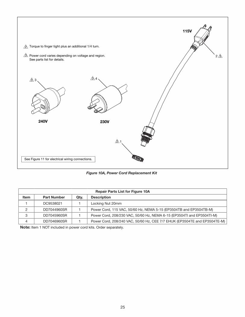
Repair Parts List for Figure 10A
Item Part Number Qty. Description
1 DC9538021 1 Locking Nut 20mm
2 DD7044960SR 1 Power Cord, 115 VAC, 50/60 Hz, NEMA 5-15 (EP3504TB and EP3504TB-M)
3 DD7045960SR 1 Power Cord, 208/230 VAC, 50/60 Hz, NEMA 6-15 (EP3504TI and EP3504TI-M)
4 DD7046960SR 1 Power Cord, 208/240 VAC, 50/60 Hz, CEE 7/7 EHUK (EP3504TE and EP3504TE-M)
Note: Item 1 NOT included in power cord kits� Order separately�
1
43
240V 230V
115V
2
Torque to finger tight plus an additional 1/4 turn.
Power cord varies depending on voltage and region. See parts list for details.
See Figure 11 for electrical wiring connections.
2
3
33
3
2
Figure 10A, Power Cord Replacement Kit
25

DIP Switch SettingsModels: EP3504TB-M EP3504TE-M EP3504TI-M
DIP Switch SettingsModels: EP3504TB EP3504TE EP3504TI
Figure 11, Electrical Block Wiring Diagram
26
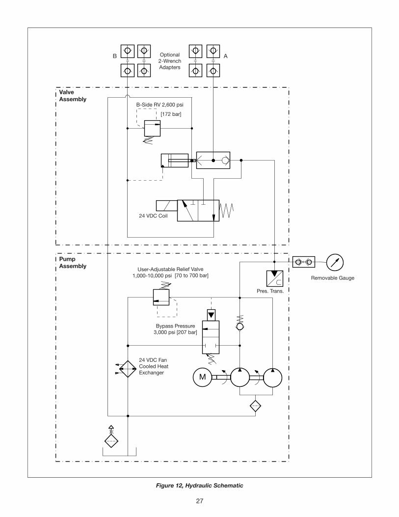
M
Pump Assembly
Valve Assembly
Removable Gauge
24 VDC FanCooled HeatExchanger
Bypass Pressure 3,000 psi [207 bar]
User-Adjustable Relief Valve1,000-10,000 psi [70 to 700 bar]
B-Side RV 2,600 psi
Optional2-WrenchAdapters
[172 bar]
24 VDC Coil
Pres� Trans�
AB
Figure 12, Hydraulic Schematic
27
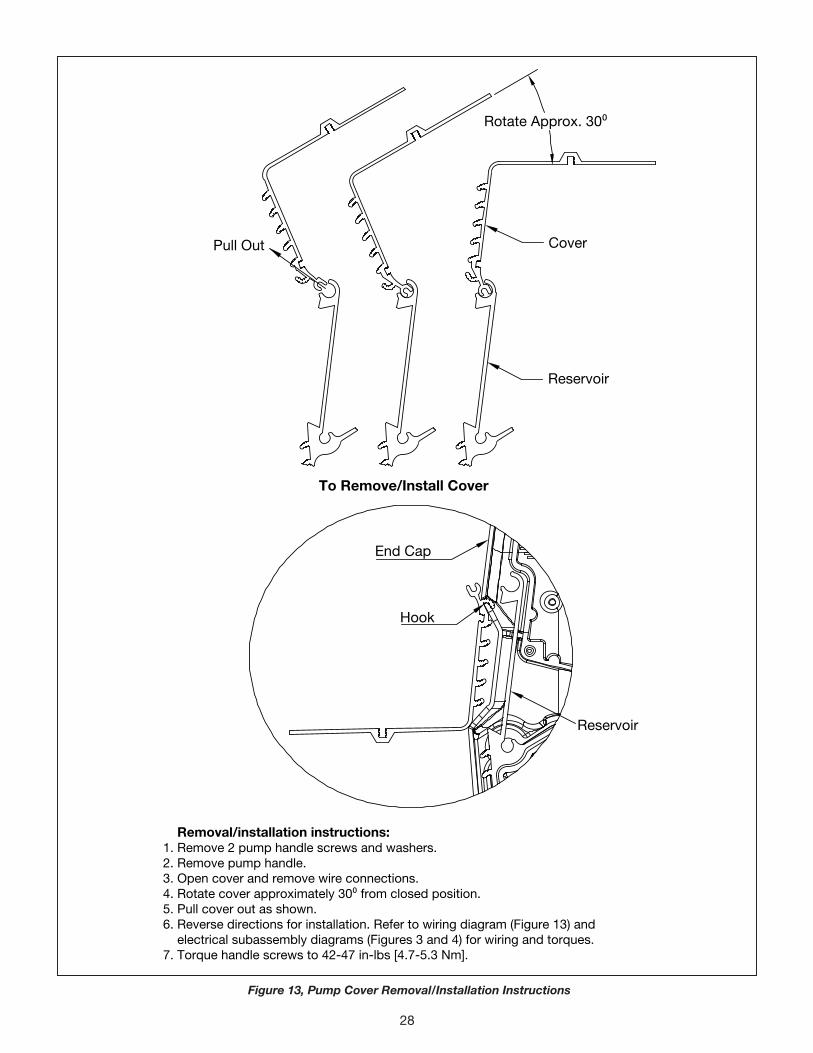
End Cap
Hook
Reservoir
Reservoir
CoverPull Out
Rotate Approx. 300
To Remove/Install Cover
Removal/installation instructions: 1. Remove 2 pump handle screws and washers. 2. Remove pump handle. 3. Open cover and remove wire connections. 4. Rotate cover approximately 300 from closed position. 5. Pull cover out as shown. 6. Reverse directions for installation. Refer to wiring diagram (Figure 13) and electrical subassembly diagrams (Figures 3 and 4) for wiring and torques. 7. Torque handle screws to 42-47 in-lbs [4.7-5.3 Nm].
Figure 13, Pump Cover Removal/Installation Instructions
28

Notes:
29

Notes:
30

Notes:
31

www.enerpac.com