A second monoclinic polymorph of 2-amino-4,6-dichloropyrimidine

ARTICLE IN PRESS
Journal of Structural Geology xx (2007) 1e12www.elsevier.com/locate/jsg
+ MODEL
Relationship between non-cylindrical fold geometry and the sheardirection in monoclinic and triclinic shear zones
Yvette D. Kuiper a,b,*, Dazhi Jiang c, Shoufa Lin b
a Department of Geology and Geophysics, Boston College, Chestnut Hill, MA 02467, USAb Department of Earth Sciences, University of Waterloo, Waterloo, Ontario, N2L 3G1, Canada
c Department of Earth Sciences, University of Western Ontario, London, Ontario, N6A 5B7, Canada
Received 2 June 2006; received in revised form 11 January 2007; accepted 30 January 2007
Abstract
We investigate the relationship between non-cylindrical fold geometry and the shear direction of the hosting high-strain zone by numericalmodeling, and show that apical axes of non-cylindrical folds may develop into directions highly oblique to the shear direction if the zone hasa pure shear component. The common practice of using well-developed sheath folds as indicators for the shear direction is not reliable and theuse of immature non-cylindrical or sheath folds appears more reliable. Hinge lines of mature sheath folds approach parallelism with the fabricattractor (to which all material lines rotate), which can have variable angles with respect to the shear direction. In thinning zones, the fabricattractor is the direction of the maximum principal strain rate of the pure shear component and is parallel to the shear zone boundary. In thick-ening zones, it lies somewhere in the quadrant between the direction of the maximum principal strain rate of the pure shear component (per-pendicular to the shear zone boundary) and the simple shear direction, and is generally oblique to the shear zone boundary. The exact locationdepends on the flow geometry of the shear zone.� 2007 Elsevier Ltd. All rights reserved.
Keywords: Sheath fold; Shear direction; Numerical modeling; High-strain zone; Transpression; Fabric
1. Introduction
Non-cylindrical folds developed in a shear zone are gener-ally accepted as indicators for shear direction (e.g. Hansen,1971; Lacassin and Mattauer, 1985; Azcarraga et al., 2002;shear-related late folds of Carreras et al., 2005) based on thesimple shear model. The relationship between the directionof non-cylindrical folds and the shear direction is expectedto be more complex in triclinic zones, but has not been inves-tigated systematically. Jiang and Williams (1999) investigatedthe development or not into sheath folds from initial dragfolds. This paper investigates the geometrical relationship of
* Corresponding author. Department of Geology and Geophysics, Boston
College, Chestnut Hill, MA 02467, USA. Tel.: þ1 617 552 3647; fax:
þ1 617 552 2462.
E-mail address: [email protected] (Y.D. Kuiper).
0191-8141/$ - see front matter � 2007 Elsevier Ltd. All rights reserved.
doi:10.1016/j.jsg.2007.01.009
Please cite this article in press as: Yvette D. Kuiper et al., Relationship between
shear zones, Struct. Geol. (2007), doi:10.1016/j.jsg.2007.01.009
non-cylindrical folds with the shear direction in general shearzones, using numerical modeling.
It has previously been demonstrated that stretching linea-tions may have varying geometrical relationships with theshear direction. For monoclinic shear zones, there are two pos-sibilities: the lineation may lie within the vorticity-normal sec-tion (VNS; Jiang and Williams, 1998; Lin et al., 1998; cf.Lister and Williams, 1983; cf. Fig. 1b) and rotate toward par-allelism with the shear direction (Lin and Williams, 1992a), orit may be parallel to the vorticity vector (Tikoff and Fossen,1999, cf. Jiang and Williams, 1998, and Lin et al., 1998).For triclinic shear zones, the stretching lineation rotation pathsare oblique to the VNS and the vorticity axis (Jiang and Wil-liams, 1998; Lin et al., 1998).
Similar to lineations, fold hinge lines rotate towards theshear direction during monoclinic progressive simple shear(Bryant and Reed, 1969; Sanderson, 1973; Bell, 1978) and
non-cylindrical fold geometry and the shear direction in monoclinic and triclinic

2 Y.D. Kuiper et al. / Journal of Structural Geology xx (2007) 1e12
+ MODEL
ARTICLE IN PRESS
(a) (b)
W
Fig. 1. A cube in a shear zone in the undeformed state (a) and after triclinic deformation (b). General progressive deformation is a combination of pure shear and
simple shear components, and is characterized by five parameters: the principal rates-of-stretch ð_3a; _3b and _3cÞ, the shear strain rate ð _gÞ and the shear direction (f,
the angle between the shear direction and the a-direction) (Jiang and Williams, 1998). The letter W indicates vorticity and VNS indicates the vorticity-normal
section. The flow is described relative to the reference frame xyz. Modified after Jiang and Williams (1999).
non-cylindrical (including sheath or tubular) folds may result(Escher and Watterson, 1974; Carreras et al., 1977; Rhodesand Gayer, 1977; Williams and Zwart, 1977; Quinquis et al.,1978; Cobbold and Quinquis, 1980; Henderson, 1981;Skjernaa, 1989; Alsop and Holdsworth, 2004). A sheath foldis a highly non-cylindrical fold, with a hinge angle (Fig. 2a)less than 90� (Skjernaa, 1989); the hinge angle is measuredbetween the parts of the hinge line that have rotated most. Ifthe hinge angle is less than 20�, the sheath fold may be calleda tubular fold (Skjernaa, 1989). In this paper, we use the term‘immature non-cylindrical fold’ for folds with hinge anglesgreater than 90�. The effect and importance of the pure shearcomponent in the formation of sheath folds was recognized byHenderson (1981) and Fletcher and Bartley (1994), but thehinge lines were still thought to rotate towards the sheardirection.
To date, non-cylindrical folds have been used to determinethe shear direction in various regions, such as the Swiss Alps(e.g. Lacassin and Mattauer, 1985), the Cabo Ortegal complexin NW Spain (e.g. Azcarraga et al., 2002) and the Newfound-land Appalachians in Canada (e.g. Brem et al., 2007). Theshear direction is thought to be parallel to the ‘cone axis’(Fowler and Kalioubi, 2002) or ‘apical axis’ (Azcarragaet al., 2002) which is the direction towards which the non-cylindrical fold convexes (Fowler and Kalioubi, 2002)(Fig. 2a). Where the apical axis is not directly measurable,
Please cite this article in press as: Yvette D. Kuiper et al., Relationship between
shear zones, Struct. Geol. (2007), doi:10.1016/j.jsg.2007.01.009
Hansen (1971) developed a method (the Hansen method) todetermine the shear direction from non-cylindrical folds.When sections of non-cylindrical folds are exposed (Figs.2a, 3) hinge lines of folds of opposite asymmetry can be plot-ted in a stereogram (lower hemisphere projection; Fig. 2b).These hinge lines plot approximately along a great circleand a separation line or angle exists between hinge lines offolds of opposite asymmetry (Fig. 2b). If a separation angleexists, the separation line (Fig. 2b) is often taken as the linebisecting the separation angle. It has roughly the same direc-tion as the apical axis. The shear direction is then taken tobe parallel to the separation line.
The practice of regarding the apical axis, as the shear direc-tion and the Hansen method are generally valid for cases ofmonoclinic progressive deformation where the fabric attractor(Passchier, 1997) lies on the VNS and where the maximumprincipal strain rate of the pure shear component (thec-direction, defined below) is parallel to the shear direction.The practice is unjustified for any other progressive deforma-tion. The complexity of non-cylindrical fold development intriclinic shear has previously been recognized; Howard(1968) and Jiang and Williams (1999) demonstrated that apicalaxes of sheath folds are oblique to stretching lineations andhinge lines of newly developed drag folds. We use numericalmodeling (Jiang and Williams, 1998; Jiang, 2007) to studythe development of initial folds into immature non-cylindrical
non-cylindrical fold geometry and the shear direction in monoclinic and triclinic

3Y.D. Kuiper et al. / Journal of Structural Geology xx (2007) 1e12
+ MODEL
ARTICLE IN PRESS
(a) (b)
Fig. 2. (a) Sheath fold geometry indicating terms used in the text for all non-cylindrical folds. The shear zone boundary is parallel to the undeformed part of the
plane that contains the sheath fold. The dashed lines indicate what exposures would look like if the fold was eroded perpendicular to the apical axis at those levels.
(b) Stereogram explaining Hansen method and terms used in the text. The orientation of the shear zone (dipping 45� to the east) and the shear direction are taken
arbitrarily. See text for discussion. All stereograms are lower hemisphere equal-angle projections.
folds, sheath folds and eventually tubular folds, as a result ofvarious types of progressive deformation including triclinicshear. The progressive deformation within the zone is basedon the unified model of Jiang and Williams (1998); the foldhinge lines are treated as material lines. The rotation of rigidellipsoidal objects in viscous flows is described by Jeffery’s(1922) theory. Since a material line can be treated as a rigidprolate object with an aspect ratio of infinity, we use themethod and program of Jiang (2007) to model the rotation offold hinge lines in this paper. The initial folds can be drag foldsor pre-existing folds, and the hinge lines need to have a pertur-bation. These initial folds do not always develop into sheathfolds. This issue has been addressed by Jiang and Williams
Please cite this article in press as: Yvette D. Kuiper et al., Relationship between
shear zones, Struct. Geol. (2007), doi:10.1016/j.jsg.2007.01.009
(1999). In this paper, we address the question under whatcircumstances the shear direction can be estimated from non-cylindrical folds that developed during shearing and, therefore,only cases where sheath folds do develop are considered. Weinvestigate various types of monoclinic and triclinic shear.We show that, in certain types of progressive deformation,the shear direction is not parallel to the apical axis and, athigher strains, it may not even lie within the separation angle.
In this paper, it is assumed that folds form in layers thatare approximately parallel to the shear zone boundary.Development of shear-related folds in layers that are obliqueto the shear zone boundary is discussed by Carreras et al.(2005).
(a) (b)
Fig. 3. Exposed sections of natural sheath folds (compare to dashed lines in Fig. 2). Trends and plunges of fold hinge lines are indicated. (a) Sheath fold from which
the approximate shear direction may be estimated (assuming that the section is not close to the fold closure). The hinge angle is high enough, and the line bisecting
the two exposed hinge lines is probably close to the shear direction. The fold closure is below the surface. (b) Sheath fold from which the shear direction may not
be estimated. The hinge angle is too low and hinge lines may have rotated towards the direction of the maximum principal strain rate of the pure shear component,
which may be different from the shear direction. See Section 4.2 for discussion.
non-cylindrical fold geometry and the shear direction in monoclinic and triclinic

4 Y.D. Kuiper et al. / Journal of Structural Geology xx (2007) 1e12
+ MODEL
ARTICLE IN PRESS
2. Progressive deformation in shear zones
Flow in a general shear zone requires five variables to char-acterize it (Fig. 1; Jiang and Williams, 1998, 1999): the shearstrain rate ð _gÞ, three principal strain rates for the pure shearcomponent ð_3a; _3b and _3cÞ and the angle ðfÞ between the sheardirection and the a-direction ð_3aÞ. In this paper, _3a ¼ 0 and _3b
¼ �_3c, such that there is no strain along the strike of the shearzone boundary and the volume is constant (as in Lin et al.,1998). Because _3b and _3c are equal in magnitude, we use thesame symbol _3 for the absolute value of both. In a thinningor transpression zone _3b is negative and _3c positive, and ina thickening or transtension zone _3b is positive and _3c negative.Constant-thickness (simple shear) zones are not consideredseparately in this paper, but they are approached by the caseswhere _g=_3 is high. We use a right-handed coordinate system,xyz (Fig. 1), such that the x-axis is parallel to the a-direction,the y-axis is normal to the shear zone boundary (parallel to theb-direction), and the z-axis is normal to the xy-plane. In Fig. 1,the xy-plane is shown to be horizontal and the shear zoneboundary (xz-plane) is vertical. However, it should be clearthat the geometries described in this paper are independentof the actual orientation of the shear zone with respect tothe geographic coordinates.
We subject initial drag fold hinge lines, which are sub-parallel to the vorticity axis of the deformation, to varioustypes of progressive deformation (and one example of a pre-existing fold to monoclinic thinning flow) by applying thevelocity gradient tensor L (Eq. 3 of Lin et al., 1998; cf.Ramberg, 1975, and Jiang and Williams, 1998), which canbe expressed as:
L¼
0@
0 _gcos f 00 �_3 00 _gsin f _3
1A ðfor thinning zonesÞ ð1aÞ
L¼
0@
0 _gcos f 00 _3 00 _gsin f �_3
1A ðfor thickenning zonesÞ ð1bÞ
The rotations of hinge lines with time, or increasing shearstrain, can be modeled using the program of Jiang (2007).The longitudinal strains (stretches) of the hinge lines at certainshear strains are calculated using the position gradient tensorF(t) (Eq. 6 of Lin et al., 1998; cf. Ramberg, 1975, and Jiangand Williams, 1998):
FðtÞ ¼
0B@
1 _g_3cos f½1� expð � _3tÞ� 0
0 expð � _3tÞ 0
0 _g_3sin fsinhð_3tÞ expð_3tÞ
1CA
ðfor thinning zonesÞ ð2aÞ
Please cite this article in press as: Yvette D. Kuiper et al., Relationship between
shear zones, Struct. Geol. (2007), doi:10.1016/j.jsg.2007.01.009
FðtÞ ¼
0BBBB@
1_g
_3cos f½expð_3tÞ � 1� 0
0 expð_3tÞ 0
0_g
_3sin fsinhð_3tÞ expð � _3tÞ
1CCCCA
ðfor thickening zonesÞ ð2bÞThe orientations and stretches of hinge lines of opposite
asymmetry (which are actually segments of one hinge line;Fig. 2), and therefore the geometry of non-cylindrical folds,at certain shear strains during progressive deformation canthus be modeled.
We model the rotation paths of fold hinge lines for varioustypes of progressive deformation by varying f and _g=_3 in Eqs.(1) and (2). In monoclinic shear, the shear direction is parallelto one of the pure shear principal strain rate directions ðf ¼0� or 90�Þ. In triclinic shear, 0� < f < 90�. In monoclinic thin-ning zones, drag folds do not develop into sheath folds whenthe shear direction is parallel to the a-direction (Jiang andWilliams, 1999). In all other types of monoclinic shear, dragfolds do develop into sheath folds (Jiang and Williams, 1999).In triclinic thinning zones, drag folds may or may not developinto sheath folds, depending on f and _g=_3, and the initial curva-ture of the drag fold hinge line (cf. Jiang and Williams, 1999).In triclinic thickening, drag folds develop into sheath folds.
3. Relationship between non-cylindrical fold geometryand the shear direction
The discussion in this section mostly concerns drag foldsdeveloped during shearing (Sections 3.1e3.4). However, theconclusions are mostly applicable to pre-existing folds aswell (see Section 3.5). We use _g$t as a measure for progressivestrain accumulation (as in Jiang and Williams, 2004). It shouldbe noted that _g$t is not the shear strain, g, parallel to the zoneboundary unless the flow is simple shear only because the pureshear component of flow also contributes to the shear strainaccumulation. The higher the _g=_3 ratio is, the closer is _g$t tothe actual shear strain parallel to the shear zone boundary, g.
3.1. Monoclinic thinning flow
In thinning shear zones, extension occurs along thec-direction and shortening along the b-direction (Fig. 1). Inmonoclinic thinning zones, drag folds develop into sheathfolds only when the shear direction is parallel to thec-direction. The c-direction is the fabric attractor and bothhinge lines rotate towards it (Fig. 4). Therefore, the apicalaxis of the non-cylindrical fold indicates the shear direction.
Fold hinge lines rotate and stretch faster, and sheath foldsdevelop faster (i.e. at lower finite shear strains) at a lower_g=_3 ratio (compare Fig. 4a and b). For example, when _g$t ¼5, the hinge angle is 83� and the stretch of the hinge lines is1.46 for _g=_3 ¼ 20 whereas the hinge angle is 26� and thestretch is 4.30 for _g=_3 ¼ 2. Extension in the direction of shearenhances sheath fold development. However, in the centre ofa shear zone, a _g=_3 ratio of 2 is probably too low to maintain,
non-cylindrical fold geometry and the shear direction in monoclinic and triclinic

5Y.D. Kuiper et al. / Journal of Structural Geology xx (2007) 1e12
+ MODEL
ARTICLE IN PRESS
(a) (b)
Fig. 4. Evolution of non-cylindrical fold geometries from drag folds in monoclinic thinning flow. The shear direction is parallel to the direction of the maximum
principal strain rate of the pure shear component, or the c-direction, and shortening occurs along the b-direction, perpendicular to the shear zone boundary. Ge-
ometries for _g=_3 ¼ 20 (a) and _g=_3 ¼ 2 (b). Wk is the kinematic vorticity number of Truesdell (1953). _g is 1 and _3 is varied in all figures. Solid arrows represent the
rotation path of S-fold hinge lines and dashed arrows the path of Z-fold hinge lines. The hinge lines lie approximately within the foliation plane, and rotate towards
the fabric attractor (fa). Solid circles represent the shear direction (sd). Non-cylindrical fold geometries to the right of the stereograms are as seen looking towards
the left in the stereograms, perpendicular to the plane that contains both hinge lines. The orientations and stretches of the hinge lines are shown with increasing
shear strain ( _g$t and g are indicated). The stretches of the hinge lines are indicated by the lengths of the lines. See text for further discussion.
because simple shear is a softening process and pure shear isa hardening one (Williams and Price, 1990; Lin et al., 1998,2007; Williams and Vernon, 2001; Williams et al., 2006).For example, in Fig. 4b, at _g$t ¼ 2, the stretch along the c-direction is 2.7, and the stretch along the b-direction is 0.37.The shear zone has thus thinned by 63% as a result of thepure shear component, and in nature the pure shear strainrate is likely to have lowered at this stage due to strain hard-ening. Therefore, a low _g=_3 ratio, if present at the early stageof deformation, is expected to become higher with increasingstrain. A _g=_3 ratio of 20 is probably much more sustainable inthe centre of a shear zone (cf. Williams et al., 2006). Near themargin of a shear zone, the _g=_3 ratio is usually low (Lin et al.,1998, 2007), but the accumulated strain is generally not highenough for sheath fold development.
3.2. Triclinic thinning flow
Sheath folds develop from drag folds in triclinic thinning inan asymmetric manner (Fig. 5). One hinge line becomessteeper, rotates initially past the c-direction towards the sheardirection and then back to the c-direction. The other hinge linerotates through horizontal and passes the shear direction to-wards the c-direction. The apical axis rotates towards parallel-ism with the c-direction, which is at a 45� angle with the sheardirection in Fig. 5a, c ðf ¼ 45�Þ. At low strain, the shear di-rection lies within the separation angle (strictly the hinge angle
Please cite this article in press as: Yvette D. Kuiper et al., Relationship between n
shear zones, Struct. Geol. (2007), doi:10.1016/j.jsg.2007.01.009
in the modeling, because there is only one fold; cf. Fig. 2), butis not parallel to the apical axis (Fig. 5c). At high strain, theshear direction does not lie within the separation angle(Fig. 5c; cf. Fig. 5a). Thus, the angle between the apicalaxis and the shear direction increases with increasing strain,in triclinic thinning. At low strain values in triclinic thinning,the apical axis of the non-cylindrical fold does approximatelyindicate the simple shear direction. If the _g=_3 were too low,then both hinge lines would rotate the same way and no sheathfold would develop (cf. Jiang and Williams, 1999).
With higher or lower values of f, geometries are similar(Fig. 5b, d). However, a lower value of f (i.e. a shallower sheardirection, e.g. 35� in Fig. 5d) requires a higher amount of strainto produce a sheath fold. For example, at _g$t ¼ 20, no sheathfold has developed yet with f ¼ 35�, while at the same _g$ta well-developed sheath fold formed if f ¼ 55�. Sheath foldformation is therefore unlikely in thinning zones for verylow values of f unless the accumulated strain is very highand sheath folds do not develop when f ¼ 0� (see above).
Also, at lower values of f, higher _g=_3 ratios are required forsheath fold development (Fig. 6). For example, at f ¼ 55� theminimum value of _g=_3 required for sheath fold development is13.2, at f ¼ 45� it is 22.7 and at f ¼ 35� it is 41.7. In thinningzones with low values of f sheath folds only develop if the _g=_3ratio is very high (Fig. 6). As the _g=_3 ratio approaches infinitythe deformation approaches simple shear (with monoclinicsymmetry).
on-cylindrical fold geometry and the shear direction in monoclinic and triclinic

6 Y.D. Kuiper et al. / Journal of Structural Geology xx (2007) 1e12
+ MODEL
ARTICLE IN PRESS
(a) (b) (c) (d)
Fig. 5. Non-cylindrical folds developing from drag folds in triclinic thinning flow. (a) Stereogram showing the rotation paths of the hinge lines for _g=_3 ¼ 50 and
f ¼ 45�. To the right, non-cylindrical fold geometries (constructed as in Fig. 4) are shown for _g=_3 ¼ 50 and f ¼ 55� (b), _g=_3 ¼ 50 and f ¼ 45� (c), and _g=_3 ¼ 50
and f ¼ 35� (d). Other annotations as in Fig. 4.
In triclinic thinning zones with low values of f (e.g. 35�;Fig. 5d), apical axes of sheath folds with hinge angles ofw80� or more approximately give the shear direction (e.g.at _g$t ¼ 40, the hinge angle is 82� and the angle betweenthe shear direction and the apical axis is 6�, which is lowenough to be useful in the field). Thus, at lower values of f,only the apical axes of immature non-cylindrical folds, andof (immature) sheath folds with greater hinge angles, indicatethe shear direction. Therefore, immature non-cylindrical and
Please cite this article in press as: Yvette D. Kuiper et al., Relationship betwee
shear zones, Struct. Geol. (2007), doi:10.1016/j.jsg.2007.01.009
sheath folds, which developed from drag folds, can be usedto estimate the shear direction by the Hansen method. The api-cal axis may be taken as the line bisecting the hinge angle (orseparation angle).
In summary, in triclinic thinning zones, the shear directionusually lies within the separation angle of immature non-cylindrical folds (cf. Fig. 5bed). It commonly lies withinthe separation angle of sheath folds at low strain values, butat high strains it does not. The shear direction rarely lies
Fig. 6. Diagram showing the minimum _g=_3 ratio required for sheath fold development from drag folds in thinning zones for various values of f. The scale of the
y-axis is varied for clarification. For the lowest values of f, the required _g=_3 is so high that the deformation approximates simple shear.
n non-cylindrical fold geometry and the shear direction in monoclinic and triclinic

7Y.D. Kuiper et al. / Journal of Structural Geology xx (2007) 1e12
+ MODEL
ARTICLE IN PRESS
within the separation angle of tubular folds in triclinic thin-ning, unless the shear direction is close to the direction ofthe maximum principal strain rate of the pure shear componentand the deformation approaches monoclinic symmetry.
3.3. Monoclinic thickening flow
In thickening zones, shortening occurs along the c-directionand extension along the b-direction. The sheath fold develop-ment shown in Fig. 7a is very similar to that shown in Fig. 4aby monoclinic thinning, because both models have a high _g=_3ratio (20), meaning that the pure shear component is low, andtherefore both models approximate simple shear.
Unlike in thinning zones, the fabric attractor for a thicken-ing zone is not the direction of the maximum principal strainrate of the pure shear component. In monoclinic thickening,it lies between the direction of the maximum principal strainrate of the pure shear component (this is the b-direction inthickening zones) and the simple shear direction. When_g=_3 is low (e.g. 2, Fig. 7b), the fabric attractor lies closerto the b-direction than when _g=_3 is high (e.g. 20, Fig. 7a).The plane that contains both non-cylindrical fold hinge linescan be at a significant angle with the shear zone boundary.The fold hinge line geometries drawn to the right of the ste-reograms in Fig. 7, which are drawn within the plane thatcontains both hinge lines, are therefore seen at an angle tothe shear zone boundary. The projection of the apical axison the a-c plane indicates the shear direction. The shear di-rection can thus be estimated by such projection (similar tothe estimation of the shear direction from stretching
Please cite this article in press as: Yvette D. Kuiper et al., Relationship between
shear zones, Struct. Geol. (2007), doi:10.1016/j.jsg.2007.01.009
lineations by projecting them onto the shear zone boundaryin simple shear, as explained by Lin and Williams, 1992a).This projection method should, strictly speaking, also beused in monoclinic thinning, but the angle between the apicalaxis and its projection on the shear zone boundary is so small(and probably not distinguishable in the field) that it can beignored.
As in monoclinic thinning, hinge lines rotate and stretchfaster, and sheath folds develop faster with a lower _g=_3 ratio(compare geometries for _g$t ¼ 5 in Fig. 7a and b). A largerpure shear component therefore enhances sheath folddevelopment.
In Fig. 8, sheath fold development as a result of monoclinicthickening is shown, with the a- and c-directions switched(compared to Fig. 7; f ¼ 0�). It requires less finite strainsto develop sheath folds when the shear direction is parallelto the a-direction (f ¼ 0�, Fig. 8) than when it is parallel tothe c-direction (f ¼ 90�, Fig. 7). The hinge lines rotate faster,but experience less stretch. This is clear when, for example,the sheath fold geometries at _g$t ¼ 5 between Figs. 7a and8a ð _g=_3 ¼ 20Þ are compared. The difference in geometriesbetween Figs. 7b and 8b ð _g=_3 ¼ 2Þ is even more striking.Thus, in monoclinic thickening, the best conditions for sheathfold development are when the _g=_3 ratio is low and the sheardirection is parallel to the a-direction.
3.4. Triclinic thickening flow
Sheath fold development in triclinic thickening zones iscomplex (Fig. 9). The fabric attractor lies somewhere in the
(a) (b)
Fig. 7. Evolution of non-cylindrical fold geometries from drag folds in monoclinic thickening flow. The shear direction is parallel to the direction of the minimum
principal strain rate of the pure shear component, or the c-direction, and extension occurs in the b-direction, perpendicular to the shear zone boundary. All other
parameters are the same as in Fig. 4.
non-cylindrical fold geometry and the shear direction in monoclinic and triclinic
8 Y.D. Kuiper et al. / Journal of Structural Geology xx (2007) 1e12
+ MODEL
ARTICLE IN PRESS
(b)(a)
Fig. 8. Same as Fig. 7, but with shear direction parallel to the a-direction ðf ¼ 0�Þ. The a- and the c-directions are reversed to avoid superposition of the two
rotation paths in the diagram. Shortening occurs parallel to the shear zone boundary, but perpendicular to the shear direction.
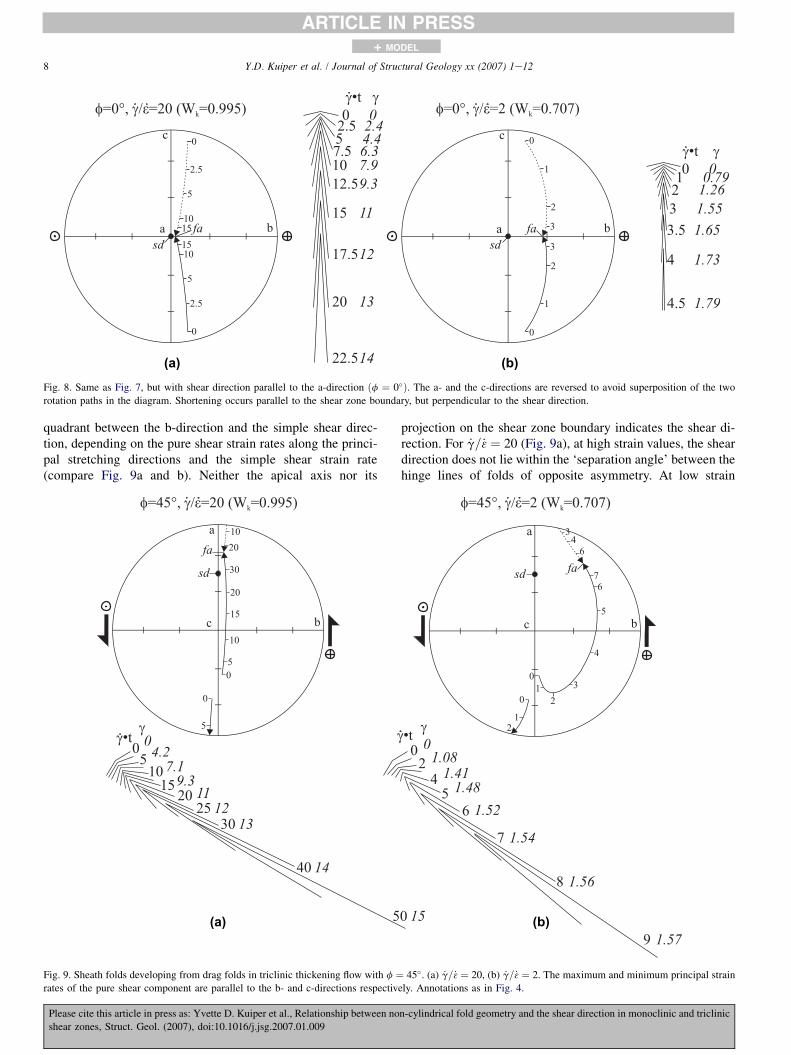
quadrant between the b-direction and the simple shear direc-tion, depending on the pure shear strain rates along the princi-pal stretching directions and the simple shear strain rate(compare Fig. 9a and b). Neither the apical axis nor its
Please cite this article in press as: Yvette D. Kuiper et al., Relationship between
shear zones, Struct. Geol. (2007), doi:10.1016/j.jsg.2007.01.009
projection on the shear zone boundary indicates the shear di-rection. For _g=_3 ¼ 20 (Fig. 9a), at high strain values, the sheardirection does not lie within the ‘separation angle’ between thehinge lines of folds of opposite asymmetry. At low strain
(a) (b)
Fig. 9. Sheath folds developing from drag folds in triclinic thickening flow with f ¼ 45�. (a) _g=_3 ¼ 20, (b) _g=_3 ¼ 2. The maximum and minimum principal strain
rates of the pure shear component are parallel to the b- and c-directions respectively. Annotations as in Fig. 4.
non-cylindrical fold geometry and the shear direction in monoclinic and triclinic

9Y.D. Kuiper et al. / Journal of Structural Geology xx (2007) 1e12
+ MODEL
ARTICLE IN PRESS
values, the apical axis does approximately indicate the simpleshear direction.
When _g=_3 ¼ 2 (Fig. 9b), the fabric attractor lies closer tothe b-direction than when _g=_3 ¼ 20 (Fig. 9a). Furthermore,the plane that contains both hinge lines rotates in a complexmanner with respect to the shear zone boundary.
3.5. Development of sheath/tubular folds froma pre-existing fold
In most cases, fold hinge lines of both pre-existing foldsand drag folds rotate towards the fabric attractor, and wheresheath folds develop, their apical axes rotate towards the fabricattractor. Therefore, in general, the conclusions drawn abovefor non-cylindrical folds developed from drag folds also applyto non-cylindrical folds developed from pre-existing folds. Anexceptional example of a pre-existing fold developing intoa sheath fold in monoclinic thinning with the shear directionparallel to the a-direction (Fig. 10) is described here in orderto illustrate how large the angle between the shear directionand the apical axis of a sheath fold can be. This example isexceptional, because a drag fold that formed in this situationwould not develop into a sheath fold. The initial hinge lineis parallel to the shear direction, which is parallel to thea-direction. The initial hinge line is given a distortion (tailends of the arrows in Fig. 10, where _g$t ¼ 0) so that a sheathfold develops during deformation. The apical axis of the non-cylindrical fold first rotates toward the shear direction andsubsequently towards the c-direction (the fabric attractor). Athigh strain values, the sheath or tubular fold direction is closeto the c-direction, and at an angle (up to 90�) with the sheardirection. One hinge line starts in a shortening field, but at
Please cite this article in press as: Yvette D. Kuiper et al., Relationship between
shear zones, Struct. Geol. (2007), doi:10.1016/j.jsg.2007.01.009
higher strain values, the stretches of the two fold hinge linesare similar. Although this particular situation may not belikely, the existence of pre-existing folds is common and thisexample confirms that apparent shear direction indicated bythe apical axis of the sheath fold may be misleading.
4. Summary and discussion
4.1. Summary
When sheath folds develop from drag folds in monoclinicthinning zones, fold hinge lines rotate towards the c-directionand the apical axes of the non-cylindrical folds indicate thesimple shear direction. In monoclinic thinning zones, sheathfolds only develop when the shear direction is parallel to thec-direction, not when it is parallel to the a-direction (Jiangand Williams, 1999).
In triclinic thinning zones, the apical axes of non-cylindrical folds that developed from drag folds are obliqueto the simple shear direction. With increasing strain, hingelines and apical axes (and any other linear structures) rotate to-wards the c-direction, not the shear direction. In other words,the apical axes of sheath folds and tubular folds are not paral-lel to the shear direction unless the shear direction is parallelto the c-direction (i.e. monoclinic thinning). However, evenin triclinic thinning zones, at low strain values, the apicalaxes of immature non-cylindrical or sheath folds approxi-mately indicate the simple shear direction. Estimating theshear direction from non-cylindrical folds, by taking the linebisecting the hinge angle (or separation angle of the Hansenmethod), is therefore reasonable as long as the non-cylindricalfolds are immature (with hinge angles more than w80�).
Fig. 10. Development of a non-cylindrical fold from a pre-existing fold in monoclinic thinning. The shear direction is parallel to the a-direction and the initial hinge
line is parallel to the shear direction (and has a perturbation). Further explanation of projections as in Fig. 4.
non-cylindrical fold geometry and the shear direction in monoclinic and triclinic
10 Y.D. Kuiper et al. / Journal of Structural Geology xx (2007) 1e12
+ MODEL
ARTICLE IN PRESS
Sheath fold development in thickening shear zones is morecomplex than in thinning shear zones, because the fabricattractor does not lie in the plane of the shear zone boundary.In monoclinic thickening, the fabric attractor lies between thedirection of the maximum principal strain rate of the pureshear component (b-direction) and the simple shear direction.The projection of the apical axis onto the shear zone boundaryindicates the shear direction. If the pure shear component ishigh, it lies close to the b-direction. If the simple shear com-ponent is high, then it lies closer to parallelism with the shearzone boundary. In triclinic thickening, the fabric attractor liessomewhere in the quadrant between the b-direction and thesimple shear direction. As for monoclinic thickening, if thepure shear component is high, it lies closer to the b-direction,and if the simple shear component is high, then it lies closer toparallelism with the shear zone boundary. However, the pro-jection of the apical axis onto the shear zone boundary doesnot indicate the shear direction.
4.2. Application in the field
Sheath folds are most likely to be found in high-strainzones with high _g=_3 ratios, because, in triclinic thinning zones,with decreasing values of f, increasing _g=_3 ratios are requiredfor sheath fold development (Fig. 6). Because simple shear iscommonly localized in the centre of a shear zone, whereaspure shear is widely distributed (Lin et al., 1998, 2007; cf.Tikoff and Teyssier, 1994, and Jones and Tanner, 1995), sheathfolds are more likely to occur in the central domain of a thin-ning shear zone than in the marginal domain. For example, Linet al. (2007) discussed the distribution, localization and parti-tioning of deformation across a thinning shear zone using anexample with f ¼ 20�. For f ¼ 20�, the minimum value of_g=_3 for sheath fold development is 125 (Fig. 6), a value whichonly occurs near the centre of Lin et al.’s (2007) shear zone.
It is evident from above that tubular folds and mature sheathfolds (with small hinge angles) are generally unreliable indica-tors of shear direction unless it is known that the kinematicframework of the deformation is of monoclinic symmetry.In thinning zones of unknown symmetry, immature non-cylindrical and sheath folds are more reliable for estimatingthe shear direction than tubular folds and mature sheath folds(Fig. 3). However, knowing the maturity of a non-cylindricalfold requires knowledge of the hinge angle. For use in the fieldthis implies that both hinge lines need to be visible (Fig. 3) andthe section of the fold that is exposed should not be too close tothe ‘nose’ of the fold, where the hinge angle appears larger. Inpractice, it is useful to keep measurements from individualnon-cylindrical folds separate from measurements from othershear zone-related folds, such that the shear direction can beestimated from individual non-cylindrical folds or groups ofsuch folds. If the estimates from folds with various hingeangles are consistent, the shear direction is likely to be closeto the c-direction (in thinning zones) or c- or a-direction (inthickening zones) and the estimated shear direction can be as-sumed to be reliable. If the orientations of the apical axes of
Please cite this article in press as: Yvette D. Kuiper et al., Relationship between
shear zones, Struct. Geol. (2007), doi:10.1016/j.jsg.2007.01.009
various folds are inconsistent, then the shear direction cannotbe estimated.
It is also useful to plot hinge lines of folds of oppositeasymmetries in a stereogram, even when the exact geometriesof the non-cylindrical folds are unknown. If these hinge lineslie within a plane that is parallel to the shear zone boundary,then the shear zone is a thinning or simple shear zone. If thehinge lines lie within a plane that is oblique to the shearzone boundary, or hinge lines seem to have rotated in a com-plex pattern, then the shear zone is probably a thickening zone.Non-cylindrical folds may be useful in determining whethera shear zone is thinning or thickening, when no other usefulindicators, such as shear bands or kink bands (Williams andPrice, 1990) are present.
4.3. Further considerations
In this paper, initial fold hinge lines of drag folds were as-sumed to develop at a high angle to the shear direction, withina plane parallel to the shear zone boundary. However, this maynot always be the case, especially when the pure shear compo-nent is large and the initial fold hinge orientation is affected bythe directions of the principal strain rate axes of the pure shearcomponent. Therefore it may be appropriate to start ourmodels with hinge lines that are oblique to the shear direction(within a plane parallel to the shear zone boundary). However,the exact angle between the initial fold hinge line and theshear direction in triclinic shear is not known at this timeand would involve a separate study that is beyond the scopeof this paper. Furthermore, the orientations of the initial hingelines of drag folds are also dependent on the orientations of thecompositional layers being folded; the latter may be at any an-gle with respect to the zone boundary at the time of fold initi-ation (cf. Carreras et al., 2005). In addition, inherited folds canhave any initial orientation. There is an infinite number of pos-sible situations. However, when the initial orientation of a foldis known, its subsequent development can be modeled follow-ing an approach similar to this investigation.
During deformation, a combination of simple shear andpure shear components determines the orientations of folia-tions and lineations (e.g. Sanderson and Marchini, 1984;Robin and Cruden, 1994; Jiang and Williams, 1998; Jonesand Holdsworth, 1998, 2004; Lin et al., 1998; Teyssier andTikoff, 1999; Tikoff and Fossen, 1999; Czeck and Hudleston,2003) and of apical axes and hinge lines of non-cylindricalfolds (this study). With increasing strain, the pure shear com-ponent becomes increasingly important for the orientations offabrics and the simple shear component becomes less impor-tant. This is especially true for thinning zones. This impliesthat the orientation of other shear sense indicators, such asasymmetric clasts, shear bands, SeC fabric, mica fish, etc.are also influenced by the pure shear component (cf. Jiangand Williams, 1998, and Lin et al., 1998). These structurestherefore may also not be reliable indicators for the sheardirection. For example, the intersection between foliation(C-fabric) and shear bands (C0-fabric) may initially not be
non-cylindrical fold geometry and the shear direction in monoclinic and triclinic
11Y.D. Kuiper et al. / Journal of Structural Geology xx (2007) 1e12
+ MODEL
ARTICLE IN PRESS
perpendicular to the shear direction and may rotate during pro-gressive deformation.
The only structures that are thought to reliably indicate theshear direction, even in triclinic deformation, are well-developed ridge-in-groove type striations (Lin and Williams,1992b; Lin et al., 1998, 2007). The presence of suchstriations indicates either monoclinic symmetry, or triclinicsymmetry with a high _g=_3 ratio. The striations would not bewell-developed in triclinic zones with a low _g=_3 ratio (Linet al., 2007). Such striations are a product of ductile deforma-tion. They occur on surfaces (ductile slickensides) exposed byparting along C-surfaces, reflecting the approximately curvi-planar geometry of the C-surfaces. The reader is referred toLin and Williams (1992b) and Lin et al. (2007) fora detailed description and discussion of such striations andtheir usage as a reliable indicator of the shear direction.
5. Conclusions
Our results show that the general practice of using well-developed sheath folds as indicators for the shear directionis often not reliable. In thinning zones, apical axes of non-cylindrical folds rotate towards the c-direction, not the sheardirection. Therefore, the apical axes of mature sheath foldsand tubular folds are not parallel to the shear direction unlessthe shear direction is parallel to the c-direction. Tubular foldsand mature sheath folds are, thus, generally unreliable indica-tors of shear direction unless it is known that the shear zoneis monoclinic. In general, in thinning zones, immature non-cylindrical and sheath folds are more reliable for estimatingthe shear direction than tubular folds and mature sheath folds.
The fact that apical axes of non-cylindrical folds may beoblique to the shear direction in triclinic shear zones, and inmonoclinic shear zones if the non-cylindrical folds developedfrom pre-existing folds, has major structural and tectonic im-plications. Mature sheath folds and tubular folds are not reli-able indicators for shear direction unless it is known that thekinematic framework of the shear zone is of monoclinic sym-metry and non-cylindrical folds originated from drag folds.Since the apical axes of sheath folds are not generally parallelto the shear direction, shear zones where the sheath folds havebeen used to determine the shear direction in the past mayneed to be reviewed. If the interpreted shear direction appearsto be incorrect or unreliable, the tectonic interpretations mayneed to be revised.
Two more practical applications of sheath folds in shearzones were found in this study. (1) When the orientations ofthe apical axes of individual non-cylindrical folds with varioushinge angles are consistent, they are likely to be a reliableindicator of the shear direction. If they are inconsistent, theshear direction cannot be estimated. (2) If hinge lines of non-cylindrical folds, or of folds of opposite asymmetries, liewithin a plane that is parallel to the shear zone boundary,the shear zone is a thinning or simple shear zone. If the hingelines lie within a plane that is oblique to the shear zone bound-ary, or hinge lines seem to have rotated in a complex pattern,then the shear zone is probably a thickening zone. Therefore,
Please cite this article in press as: Yvette D. Kuiper et al., Relationship betwee
shear zones, Struct. Geol. (2007), doi:10.1016/j.jsg.2007.01.009
non-cylindrical folds may help to determine whether a shearzone is thinning or thickening.
Acknowledgements
The research was conducted while YDK was a post-doctoral fellow at the University of Waterloo, supported byNatural Sciences and Engineering Research Council ofCanada (NSERC) Collaborative Research and Developmentgrant to SL. YDK and SL acknowledge support from Mani-toba Geological Survey and Manitoba Hydro. DJ and SL ac-knowledge support from their respective NSERC discoverygrants. Constructive journal reviews by Jean Crespi andDyanna Czeck are greatly appreciated.
References
Alsop, G.I., Holdsworth, R.E., 2004. The geometry and topology of natural
sheath folds: a new tool for structural analysis. Journal of Structural
Geology 26, 1561e1589.
Azcarraga, J., �Abalos, B., Gil Ibarguchi, J.I., 2002. On the relationship be-
tween kilometer-scale sheath folds, ductile thrusts and minor structures
in the basal high-pressure units of the Cabo Ortegal complex (NW Spain).
Journal of Structural Geology 24, 1971e1989.
Bell, T.H., 1978. Progressive deformation and reorientation of fold axes in a
ductile mylonite zone: the Woodroffe thrust. Tectonophysics 44, 285e320.
Brem, A.G., Lin, S., van Staal, C.R., Davis, D.W., McNicoll, V.C., 2007. The
Middle Ordovician to Early Silurian voyage of the Dashwoods micro-con-
tinent, West Newfoundland: based on new U/Pb and 40Ar/39Ar geochrono-
logical and kinematic constraints. American Journal of Science 200.
Bryant, B., Reed, J.C., 1969. Significance of lineation and minor folds near
major thrust faults in the Southern Appalachians and the British and
Norwegian Caledonides. Geological Magazine 106, 412e429.
Carreras, J., Druguet, E., Griera, A., 2005. Shear zone-related folds. Journal of
Structural Geology 27, 1229e1251.
Carreras, J., Estrada, A., White, S., 1977. The effects of folding on the c-axis
fabrics of a quartz-mylonite. Tectonophysics 39, 3e24.
Cobbold, P.R., Quinquis, H., 1980. Development of sheath folds in shear
regimes. Journal of Structural Geology 2, 119e126.
Czeck, D.M., Hudleston, P.J., 2003. Testing for obliquely plunging lineations
in transpression: a natural example and theoretical discussion. Journal of
Structural Geology 25, 959e982.
Escher, A., Watterson, J., 1974. Stretching fabric, folds and crustal shortening.
Tectonophysics 22, 223e231.
Fletcher, J.M., Bartley, J.M., 1994. Constrictional strain in a non-coaxial shear
zone: implications for fold and rock fabric development, central Mojave
metamorphic core complex, California. Journal of Structural Geology
16, 555e570.
Fowler, A.-R., Kalioubi, B.E., 2002. The MigifeHafafit gneissic complex of
the Egyptian Eastern Desert: fold interference patterns involving multiply
deformed sheath folds. Tectonophysics 346, 247e275.
Hansen, E., 1971. Strain Facies. Springer-Verlag, Berlin, 207 pp.
Henderson, J.R., 1981. Structural analysis of sheath folds with horizontal
x-axes, northeast Canada. Journal of Structural Geology 3, 203e210.
Howard, K.A., 1968. Flow direction in triclinic foliated rocks. American
Journal of Science 266, 758e765.
Jeffery, G.B., 1922. The motion of ellipsoidal particles immersed in a viscous
fluid. Proceedings of the Royal Society of London A 102, 161e179.
Jiang, D., 2007. Numerical modeling of the motion of rigid ellipsoidal objects
in slow viscous flows: a new approach. Journal of Structural Geology 29,
189e200.
Jiang, D., Williams, P.F., 1998. High-strain zones: a unified model. Journal of
Structural Geology 20, 1105e1120.
n non-cylindrical fold geometry and the shear direction in monoclinic and triclinic

12 Y.D. Kuiper et al. / Journal of Structural Geology xx (2007) 1e12
+ MODEL
ARTICLE IN PRESS
Jiang, D., Williams, P.F., 1999. When do dragfolds not develop into sheath
folds in shear zones? Journal of Structural Geology 21, 577e583.
Jiang, D., Williams, P.F., 2004. Reference frame, angular momentum, and
porphyroblast rotation. Journal of Structural Geology 26, 2211e2224.
Jones, R.R., Holdsworth, R.E., 1998. Oblique simple shear in transpression
zones. In: Holdsworth, R.E., Strachan, R.A., Dewey, J.F. (Eds.), Continen-
tal Transpressional and Transtensional Tectonics. Geological Society,
London, Special Publications, vol. 135, pp. 35e40.
Jones, R.R., Holdsworth, R.E., 2004. Inclined transpression. Journal of Struc-
tural Geology 26, 1531e1548.
Jones, R.R., Tanner, P.W.G., 1995. Strain partitioning in transpression zones.
Journal of Structural Geology 17, 793e802.
Lacassin, R., Mattauer, M., 1985. Kilometre-scale sheath fold at Mattmark and
implications for transport direction in the Alps. Nature 315, 739e742.
Lin, S., Williams, P.F., 1992a. The geometrical relationship between the
stretching lineation and the movement direction in shear zones. Journal
of Structural Geology 14, 491e497.
Lin, S., Williams, P.F., 1992b. The origin of ridge-in-groove slickenside striae
and associated steps in an SeC mylonite. Journal of Structural Geology
14, 315e321.
Lin, S., Jiang, D., Williams, P.F., 1998. Transpression (or transtension) zones
of triclinic symmetry: natural example and theoretical modeling. In:
Holdsworth, R.E., Strachan, R.A., Dewey, J.F. (Eds.), Continental Trans-
pressional and Transtensional Tectonics. Geological Society, London,
Special Publications, vol. 135, pp. 41e57.
Lin, S., Jiang, D., Williams, P.F., 2007. Importance of differentiating ductile
slickenside striations from stretching lineations and variation of shear di-
rection across a high-strain zone. Journal of Structural Geology, in press.
doi:10.1016/j.jsg.2006.12.006.
Lister, G.S., Williams, P.F., 1983. The partitioning of deformation in flowing
rock masses. Tectonophysics 92, 1e33.
Passchier, C.W., 1997. The fabric attractor. Journal of Structural Geology 19,
113e127.
Quinquis, H., Audren, C.L., Brun, J.P., Cobbold, P.R., 1978. Intense progres-
sive shear in the Ile de Groix blueschists. Nature 273, 43e45.
Ramberg, H., 1975. Particle paths, displacement and progressive strain appli-
cable to rocks. Tectonophysics 28, 10e37.
Please cite this article in press as: Yvette D. Kuiper et al., Relationship between
shear zones, Struct. Geol. (2007), doi:10.1016/j.jsg.2007.01.009
Rhodes, S., Gayer, R.A., 1977. Non-cylindrical folds, linear structures in the
X direction and mylonite developed during translation of the Caledonian
Kalak Nappe Complex of Finmark. Geological Magazine 114, 329e341.
Robin, P.-Y.F., Cruden, A.R., 1994. Strain and vorticity patterns in ideally duc-
tile transpression zones. Journal of Structural Geology 16, 447e466.
Sanderson, D.J., 1973. The development of fold axes oblique to the regional
trend. Tectonophysics 16, 55e70.
Sanderson, D.J., Marchini, W.R.D., 1984. Transpression. Journal of Structural
Geology 6, 449e458.
Skjernaa, L., 1989. Tubular folds, and sheath folds: definitions and conceptual
models for their development, with examples from the Grapesvare area,
northern Sweden. Journal of Structural Geology 11, 689e703.
Teyssier, C., Tikoff, B., 1999. Fabric stability in oblique convergence and
divergence. Journal of Structural Geology 21, 969e974.
Tikoff, B., Fossen, H., 1999. Three-dimensional reference deformations and
strain facies. Journal of Structural Geology 21, 1497e1512.
Tikoff, B., Teyssier, C., 1994. Strain modeling of displacement-field partition-
ing in transpressional orogens. Journal of Structural Geology 16, 1575e
1588.
Truesdell, C., 1953. Two measures of vorticity. Journal of Rational Mechanical
Analysis 2, 173e217.
Williams, P.F., Price, G.P., 1990. Origin of kinkbands and shear-band cleavage
in shear zones: an experimental study. Journal of Structural Geology 12,
145e164.
Williams, P.F., Vernon, R.H., 2001. Origin of a vertical lineation in transcur-
rent conjugate shear zones at Broken Hill, Australia. Tectonophysics
335, 163e182.
Williams, P.F., Zwart, H.J., 1977. A model for the development of the Sevee
Kolli Caledonian nappe complex. In: Saxena, S.K., Bhattacharji, S.
(Eds.), Energetics of Geological Processes. Springer, New York, pp.
169e187.
Williams, P.F., Jiang, D., Lin, S., 2006. Interpretation of deformation fabrics of
infrastructure zone rocks in the context of channel flow and other tectonic
models. In: Law, R.D., Searle, M., Godin, L. (Eds.), Channel Flow,
Ductile Extrusion and Exhumation of Lower-mid Crust in Continental Col-
lision Zones. Geological Society, London, Special Publications, Vol. 268,
pp. 221e235.
non-cylindrical fold geometry and the shear direction in monoclinic and triclinic
Copyright © 2022 FDOKUMEN