
Multiple strategies for O2 transport: from simplicity to complexity
A554 Journal of The Electrochemical Society, 161 (4) A554-A560 (2014)0013-4651/2014/161(4)/A554/7/$31.00 © The Electrochemical Society
Reduced Graphene Oxide-Polypyrrole Composite as a Catalystfor Oxygen Electrode of High Rate Rechargeable Li-O2 CellsC. Selvaraj,a Surender Kumar,a N. Munichandraiah,a,∗,z and L. G. Scanlonb,∗
aDepartment of Inorganic and Physical Chemistry, Indian Institute of Science, Bangalore 560012, IndiabAir Force Research Laboratory, Electrical Systems Branch, Wright-Patterson Air Force Base, Ohio 45433, USA
Polypyrrole (PPY) is grown on reduced graphene oxide (RGO) and the composite is studied as a catalyst for O2 electrode in Li-O2cells. PPY is uniformly distributed on the two dimensional RGO layers. Li-O2 cells assembled in a non-aqueous electrolyte usingRGO-PPY catalyst exhibit an initial discharge capacity as high as 3358 mAh g−1 (3.94 mAh cm−2) at a current density of 0.3 mAcm−2. The voltage gap between the charge and discharge curves is less for Li-O2(RGO-PPY) cell in comparison with Li-O2(RGO)cell. The Li-O2(RGO-PPY) cell delivers a discharge capacity of 550 mAh g−1 (0.43 mAh cm−2) at a current density of 1.0 mAcm−2. The results suggest that RGO-PPY is a promising catalyst of O2 electrode for high rate rechargeable Li-O2 cells.© 2014 The Electrochemical Society. [DOI: 10.1149/2.055404jes] All rights reserved.
Manuscript submitted September 12, 2013; revised manuscript received January 17, 2014. Published February 12, 2014.
There are several bifunctional electrocatalysts reported forrechargeable Li-O2 cells.1–14 Abraham and Jiang1 first reported apolymer electrolyte based Li-O2 cell using cobalt phthalocyanineas the catalyst for O2 electrode. Ogasawara et al.2 used electrolyticmanganese dioxide as the catalyst. Other catalysts reported forO2 electrode include Mn3O4,3 α-MnO2 nanowires,4 Fe2O3, Fe3O4,CuO and CoFe2O4,5 Pt particles,6 Pd/MnO2 composite,7 carbonsupported MnOx,8 Pt-Au nanoparticles,9 CoMn2O4 spinel/graphenecomposite,10 graphene,11,12 lithium phthalocyanine,13 polypyrrole(PPY),14 etc.
Graphene, which is a two dimensional planar sheet of sp2
bonded carbon atoms, is studied for electrochemical energy storageapplications.15,16 It has been studied for applications in fuel cells,17
electrical double-layer capacitors,18 Li-ion batteries19 and also for Li-air cells.11,12 Li et al.11 compared discharge-charge performance ofLi-O2 cells with O2 electrodes made of graphene and carbons. Thecells with graphene delivered a discharge capacity of about 8700 mAhg−1, which was the highest capacity among three different carbon sam-ples studied. As examined by microscopy, graphene nano sheets pos-sessed curly morphology with thin, wrinkled structure. These uniquestructures provided ideal porosity, which was suitable for the elec-trolyte wetting and O2 diffusion, thus delivering a high dischargecapacity. After the cell discharge, the reaction products deposited onboth sides of graphene nano sheets, but more deposits were observedon edges. The edge sites, which contained large amounts of unsatu-rated carbon atoms, were highly active to react with O2 and to formoxygen-containing groups. Therefore, the presence of unsaturated car-bon atoms was inferred as responsible to provide high activity foroxygen reduction reaction.11 In this study,11 the first discharge of Li-O2 cells was only studied, but the rechargeability of the cells was notreported. The conducting polymer, PPY is an attractive polymer withadvantages such as a high electronic conductivity, chemical and elec-trochemical stability, etc. PPY sample with tubular as well as granularmorphology were prepared and studied as supports for O2-electrodein Li-O2 rechargeable cells using electrolytic MnO2 nanoparticles asthe catalyst.14 Tubular PPY provided greater discharge capacity thangranular PPY.
As described above, graphene has attracted a great attention as asupport for electrocatalysts and battery electrode materials. This isdue to high electrical conductivity, high thermal conductivity and alarge specific surface area. Graphene sheets prepared by chemical re-duction of graphene oxide possess a large defect sites on surfaces aswell as edges. Polypyrrole is also an attractive material due to its highelectronic conductivity and electrochemical activity. The presence ofstructural defects on both graphene and PPY can facilitate adsorptionof solution species and also gas molecules. A combination of advan-tages of graphene and PPY is envisaged from a composite of these
∗Electrochemical Society Active Member.zE-mail: [email protected]
constituents for studying in Li-O2 cells. In the present study, PPY isgrown uniformly on reduced graphene oxide (RGO), and the resultingcomposite is used as the catalyst for O2 electrode reaction in Li-O2
cells. A discharge capacity as high as 3358 mAh g−1 (3.94 mAh cm−2)is obtained at a current density of 0.3 mA cm−2. The cell delivers adischarge capacity of about 550 mAh g−1 (0.48 mAh cm−2) at a cur-rent density as high as 1.0 mA cm−2. Details of these studies arepresented.
Experimental
Graphite oxide was prepared by Hummer’s method20 by the oxi-dation of graphite powder (Graphite India) using KMnO4 (S. D. FineChemicals) as the oxidizing agent in H2SO4 (S. D. Fine Chemicals)consisting of NaNO3 (S. D. Fine Chemicals). Graphite oxide was dis-persed in distilled water and exfoliated by sonication for 3 h usingMisonix Ultrasonicator model S4000–010 at a frequency of 20 kHzand power of 600 W with a Ti horn dipped in the dispersion. Theso formed graphene oxide was separated, dispersed in water, addedNH4OH to increase pH to 10 and reduced by NaBH4 (S.D. FineChemicals) at 80◦C. The reduced graphene oxide (RGO) was sepa-rated by centrifugation, washed with double-distilled water repeatedlyand dried at 80◦C.
For the preparation of RGO-PPY composite, 1 mL pyrrole(Aldrich) was dissolved in 10 mL 0.1 M HCl (S.D. Fine Chemi-cals) and 100 mg RGO was added. The mixture was stirred for 12 h atambient conditions and cooled to < 4◦C in an ice bath. Ammoniumpersulphate (3.6 g, RANKEM) was dissolved in 0.1 M HCl, cooledto < 4◦C, and then added drop-wise to the suspension consisting ofRGO and pyrrole. The contents were stirred for 6 h to facilitate theoxidation of pyrrole to PPY. The RGO-PPY (weight ratio 1:1) com-posite was separated by centrifugation, washed repeatedly with waterand finally with ethanol. It was dried at 50◦C.
For the fabrication of O2 electrodes, porous carbon paper (Toray)of 2.0 mm thickness was used as the current collector. A circular(12 mm diameter) disk was punched out of a sheet of Toray carbonpaper. High surface area (1500 cm2 g−1) carbon powder (Fuzhou Yi-huan Carbon, Co., China) and PTFE suspension (Aldrich) were mixedin 7:3 weight ratio. A minimum quantity of water was added to forma dough, which was rolled into a layer. This layer was applied onone side of the carbon paper current collector. The RGO-PPY catalyst(18.5 mg) and PVDF (1.5 mg, Aldrich) were mixed (weight ratio:92.5 : 7.5) in a mortar, a few drops of n-methyl pyrrolidone (Aldrich)were added and mixed again to form an ink. The ink was applied onthe other side of the carbon paper. The sandwich of diffusion-layer,carbon paper and catalyst-layer was pressed in a die at a pressureof 50 kN for 3 min. The electrode was dried at 100◦C for 12 h andtransferred into an argon filled MBraun glove box model Unilab.The mass of RGO-PPY catalyst was in the range 0.8–1.0 mg on theporous carbon paper current collector. Li-O2 cells were assembled in
ecsdl.org/site/terms_use address. Redistribution subject to ECS license or copyright; see 14.139.128.11Downloaded on 2014-02-13 to IP
Journal of The Electrochemical Society, 161 (4) A554-A560 (2014) A555
home-made Swagelok-type PTFE containers. The container had pro-vision to close one side where Li disk anode was placed and theother side open for exposure to oxygen gas from a cylinder. A Li diskused as the anode (12 mm diameter) was punched out of a ribbon(0.3 mm thick, Aldrich) and its surface was scraped with a knife toremove an outer layer on both sides of it. Stainless steel current col-lectors were used to take electrical contacts from the electrodes. TheLi disk, a glass mat separator and the air electrode were sandwichedinside the PTFE container and stainless steel electric contacts wereinserted and sealed.13,21 The glass mat was soaked in the electrolyte,which was made of 1.0 M LiPF6 in tetraethylene glycol dimethyl ether(TEGDME), before inserting into the cell. The volume of electrolyteis approximately 0.3–0.5 mL. The catalyst layer of the O2 electrodewas exposed to the electrolyte and the diffusion-layer to oxygen gas.
Powder X-ray diffraction (XRD) patterns were recorded usinga Philips ‘X’PERT PRO diffractometer with Cu-Kα radiation (λ:1.5438 Å) as the X-ray source. Microscopy of the samples was carriedout using FEI Tecnai T-20 200 kV transmission electron microscope(TEM). Charge-discharge cycling of Li-O2 cells was carried out byusing Bitrode battery cycling equipment in an air-conditioned roomat 22 ± 1◦C.
Results and Discussion
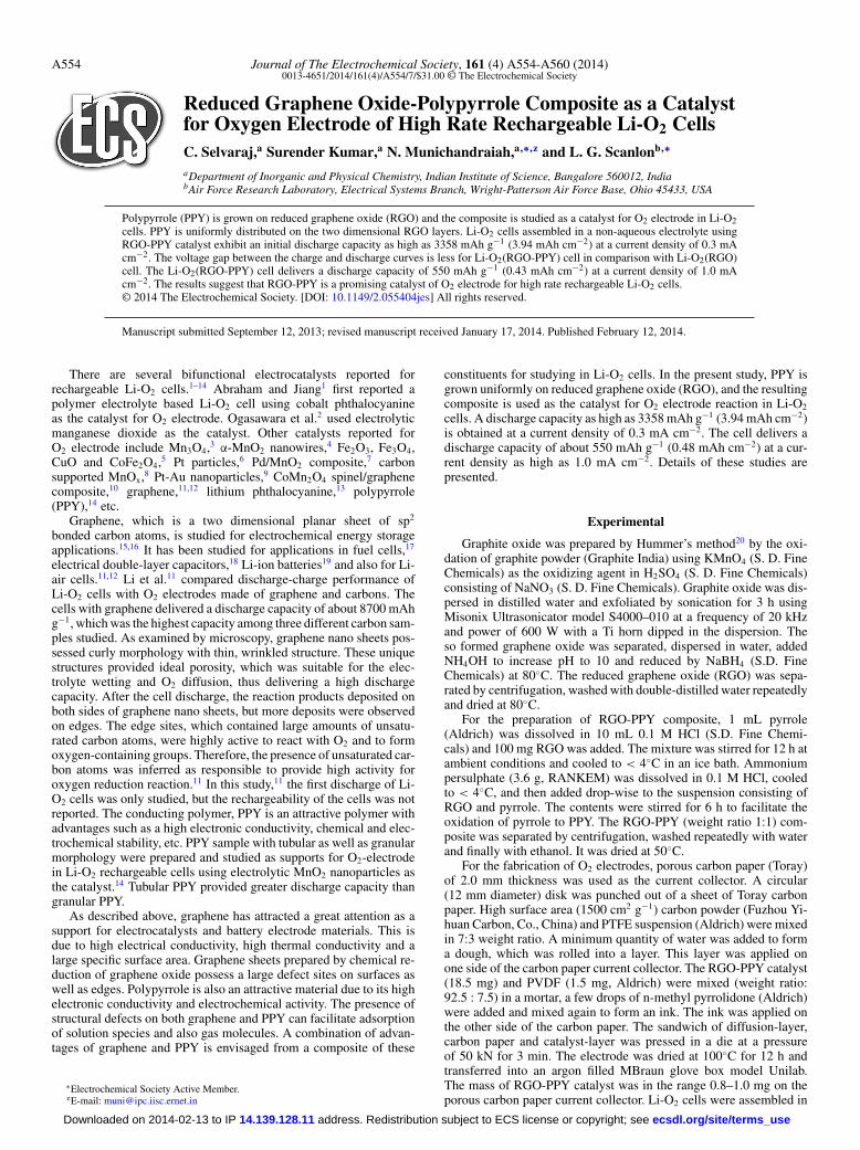
Physicochemical studies.— Formations of RGO and RGO-PPYcomposite were investigated by powder XRD patterns (Fig. 1). Forgraphite, a strong reflection at 26.45◦ is attributed to (002) plane ofhexagonal graphitic structure with d-spacing of 3.36 Å (Fig. 1a). Af-ter oxidation, the peak is shifted to 10.42◦ (Fig. 1a) correspondingto d spacing of 8.47 Å. A large increase in d-spacing is due to theexpansion of graphitic sheet resulting from bonding of oxygen func-tionalities on both sides of graphene sheets.22 After reduction, thepeak corresponding to (002) plane for RGO is shifted back to a lowerd space value (Fig. 1a), because of removal of oxygen functionali-ties. The broad, weak intensity of 21.19◦ reflection indicates a shortrange order of RGO stacked sheets. The XRD of RGO-PPY com-posite has a low intensity reflection at 24.30◦, which is broader thanthe reflection of RGO in the absence of PPY. This feature supportsthe presence of PPY on graphene sheets.23 Both RGO and RGO-PPYcomposites were studied by Raman spectroscopy (Fig. 1b). Ramanspectra were recorded between 200 and 3200 cm−1 at an excitationwavelength of 514 nm. The RGO spectrum shows intense bands at1588 and 1350 cm−1
, which are known as G and D bands of graphenesheets arising from in plane vibration of graphite lattice (E2g) and thedefect sites of smaller graphene domains, respectively.24,25 In additionto these bands, the spectrum of RGO-PPY also contains less intensebands at 639, 933, 973 and 1048 cm−1. The bands near 1588 and1350 cm−1 of PPY-RGO are also attributed the π-conjugated struc-ture and ring stretching mode of PPY backbone, respectively.26 Theband at 1048 cm−1 is due to the C-H in plane deformation arisingfrom pyrrole ring, and the bands at 973 and 933 cm−1 are associatedwith the quinoid polaronic and bipolaronic structure, respectively.26
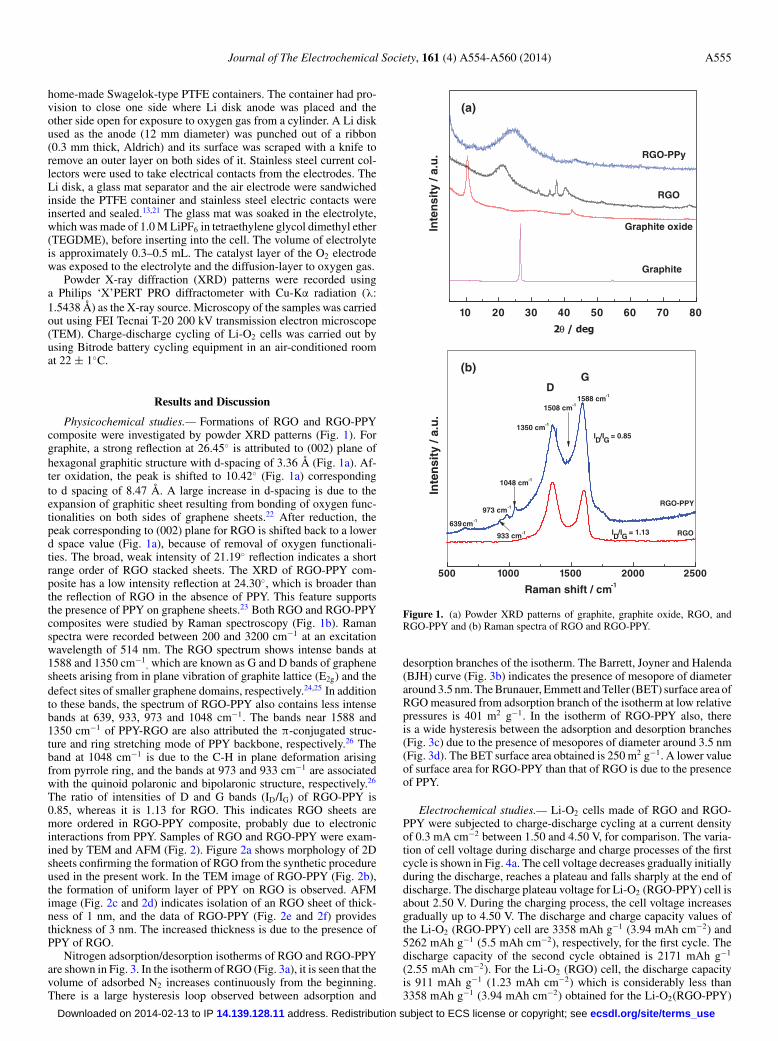
The ratio of intensities of D and G bands (ID/IG) of RGO-PPY is0.85, whereas it is 1.13 for RGO. This indicates RGO sheets aremore ordered in RGO-PPY composite, probably due to electronicinteractions from PPY. Samples of RGO and RGO-PPY were exam-ined by TEM and AFM (Fig. 2). Figure 2a shows morphology of 2Dsheets confirming the formation of RGO from the synthetic procedureused in the present work. In the TEM image of RGO-PPY (Fig. 2b),the formation of uniform layer of PPY on RGO is observed. AFMimage (Fig. 2c and 2d) indicates isolation of an RGO sheet of thick-ness of 1 nm, and the data of RGO-PPY (Fig. 2e and 2f) providesthickness of 3 nm. The increased thickness is due to the presence ofPPY of RGO.
Nitrogen adsorption/desorption isotherms of RGO and RGO-PPYare shown in Fig. 3. In the isotherm of RGO (Fig. 3a), it is seen that thevolume of adsorbed N2 increases continuously from the beginning.There is a large hysteresis loop observed between adsorption and
10 20 30 40 50 60 70 80
2θ / deg
(a)
Inte
nsi
ty /
a.u
.
RGO
Graphite
Graphite oxide
RGO-PPy
500 1000 1500 2000 2500
Inte
nsi
ty /
a.u
.
D
RGO
RGO-PPY
G
Raman shift / cm-1
(b)
ID/IG = 1.13
ID/IG = 0.85
1588 cm-1
1350 cm-1
639 cm-1
933 cm-1
973 cm-1
1048 cm-1
1508 cm-1
Figure 1. (a) Powder XRD patterns of graphite, graphite oxide, RGO, andRGO-PPY and (b) Raman spectra of RGO and RGO-PPY.
desorption branches of the isotherm. The Barrett, Joyner and Halenda(BJH) curve (Fig. 3b) indicates the presence of mesopore of diameteraround 3.5 nm. The Brunauer, Emmett and Teller (BET) surface area ofRGO measured from adsorption branch of the isotherm at low relativepressures is 401 m2 g−1. In the isotherm of RGO-PPY also, thereis a wide hysteresis between the adsorption and desorption branches(Fig. 3c) due to the presence of mesopores of diameter around 3.5 nm(Fig. 3d). The BET surface area obtained is 250 m2 g−1. A lower valueof surface area for RGO-PPY than that of RGO is due to the presenceof PPY.
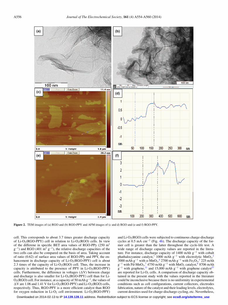
Electrochemical studies.— Li-O2 cells made of RGO and RGO-PPY were subjected to charge-discharge cycling at a current densityof 0.3 mA cm−2 between 1.50 and 4.50 V, for comparison. The varia-tion of cell voltage during discharge and charge processes of the firstcycle is shown in Fig. 4a. The cell voltage decreases gradually initiallyduring the discharge, reaches a plateau and falls sharply at the end ofdischarge. The discharge plateau voltage for Li-O2 (RGO-PPY) cell isabout 2.50 V. During the charging process, the cell voltage increasesgradually up to 4.50 V. The discharge and charge capacity values ofthe Li-O2 (RGO-PPY) cell are 3358 mAh g−1 (3.94 mAh cm−2) and5262 mAh g−1 (5.5 mAh cm−2), respectively, for the first cycle. Thedischarge capacity of the second cycle obtained is 2171 mAh g−1
(2.55 mAh cm−2). For the Li-O2 (RGO) cell, the discharge capacityis 911 mAh g−1 (1.23 mAh cm−2) which is considerably less than3358 mAh g−1 (3.94 mAh cm−2) obtained for the Li-O2(RGO-PPY)
ecsdl.org/site/terms_use address. Redistribution subject to ECS license or copyright; see 14.139.128.11Downloaded on 2014-02-13 to IP
A556 Journal of The Electrochemical Society, 161 (4) A554-A560 (2014)
(a) (b)
(c) (d)
(e) (f)
Figure 2. TEM images of (a) RGO and (b) RGO-PPY and AFM images of (c and d) RGO and (e and f) RGO-PPY.
cell. This corresponds to about 3.7 times greater discharge capacityof Li-O2(RGO-PPY) cell in relation to Li-O2(RGO) cells. In viewof the differene in specific BET area values of RGO-PPy (250 m2
g−1) and RGO (401 m2 g−1), the relative discharge capacities of thetwo cells can also be compared on the basis of area. Taking accountof ratio (0.62) of surface area values of RGO-PPy and PPY, the en-hancement in discharge capacity of Li-O2(RGO-PPY) cell is about2.3 times of the capacity of Li-O2(RGO) cell. Thus, the increase incapacity is attributed to the presence of PPY in Li-O2(RGO-PPY)cells. Furthermore, the difference in voltages (�V) between chargeand discharge is also smaller for Li-O2(RGO-PPY) cell than for Li-O2(RGO) cell. For instance, at a capacity of 50 mAh g−1, the values of�V are 1.06 and 1.41 V for Li-O2(RGO-PPY) and Li-O2(RGO) cells,respectively. Thus, RGO-PPY is a more efficient catalyst than RGOfor oxygen reduction in Li-O2 cell environment. Li-O2(RGO-PPY)
and Li-O2(RGO) cells were subjected to continuous charge-dischargecycles at 0.5 mA cm−2 (Fig. 4b). The discharge capacity of the for-mer cell is greater than the latter throughout the cycle-life test. Awide range of discharge capacity values are reported in the litera-ture. For instance, discharge capacity of 1400 mAh g−1 with cobaltphathalocyanine catalyst,1 1000 mAh g−1 with electrolytic MnO2,2
3000 mAh g−1 with α-MnO2,4 2700 mAh g−1 with Fe2O3,5 225 mAhg−1 with Pd-MnO2,7 4750 mAh g−1 with MnO2 catalyst,8 8706 mAhg−1 with graphene,11 and 15,000 mAh g−1 with graphene catalyst27
are reported for Li-O2 cells. A comparison of discharge capacity ob-tained in the present study with the values reported in the literaturecould be inconclusive because there is no uniformity in experiementalconditions such as cell configurations, current collectors, electrodesfabrication, nature of the catalyst and their loading levels, electrolytes,current densities used for charge-discharge cycling, etc. Nevertheless,
ecsdl.org/site/terms_use address. Redistribution subject to ECS license or copyright; see 14.139.128.11Downloaded on 2014-02-13 to IP

Journal of The Electrochemical Society, 161 (4) A554-A560 (2014) A557
0.0 0.2 0.4 0.6 0.8 1.0
0
100
200
300
400
500
Vo
lum
e o
f N
2 / c
m3
g-1
Relative pressure / (p/p0)
(c)
0 2 4 6 8 10 12 14 16 18 20
0.0
0.1
0.2
0.3
0.4
0.5
0.6
0.7(d
Vo
l / d
Dia
) / c
m3
g-1
nm
-1
Pore diameter / nm
(d)
0.0 0.2 0.4 0.6 0.8 1.00
50
100
150
200
250
300
Vo
lum
e o
f N
2 / c
m3
g-1
Relative pressure / (p/p0)
(a)
0 2 4 6 8 10 12 14 16 18 20
0.0
0.1
0.2
0.3
0.4
0.5
0.6
0.7
(dV
ol /
dD
ia)
/ cm
3 g
-1 n
m-1
Pore diameter / nm
(b)
Figure 3. (a) N2 adsorption – desorptionisotherm and (b) BJH pore size distribution ofRGO; (c) N2 adsorption – desorption isothermand (d) BJH pore size distribution of RGO-PPy.
a discharge capacity of 3358 mAh g−1 (3.94 mAh cm−2) obtained forLi-O2(RGO-PPY) cell is an attractively high value.
The charge-discharge reactions occurring in a Li-O2 cell are asfollows.
At the Li electrode,
Li+ + e− charge−−−−−→←−−−−−discharge
Li [1]
Oxidation of Li metal leading to release of Li+ ions during the celldischarge and reduction of Li+ ions leading to deposition of Li metalare expected at the negative electrode. The reduction of O2 in Li+
ion containing non-aqueous electrolytes results in the formation ofLi2O2 and Li2O as stable products at the positive electrode during thedischarge of Li-O2 cell.1 Taking account of several reports availablein literature, Laoire et al.27 proposed the following mechanism foroxygen reduction:
O2 + Li+ + e− discharge−−−−−→←−−−−−charge
LiO2 [2]
LiO2 + Li+ + e− discharge−−−−−→←−−−−−charge
Li2O2 [3]
Li2O2 + 2Li+ + 2e− discharge−−−−−→←−−−−−charge
2Li2O [4]
Single-electron transfer reduction of O2 produces superoxide(O2
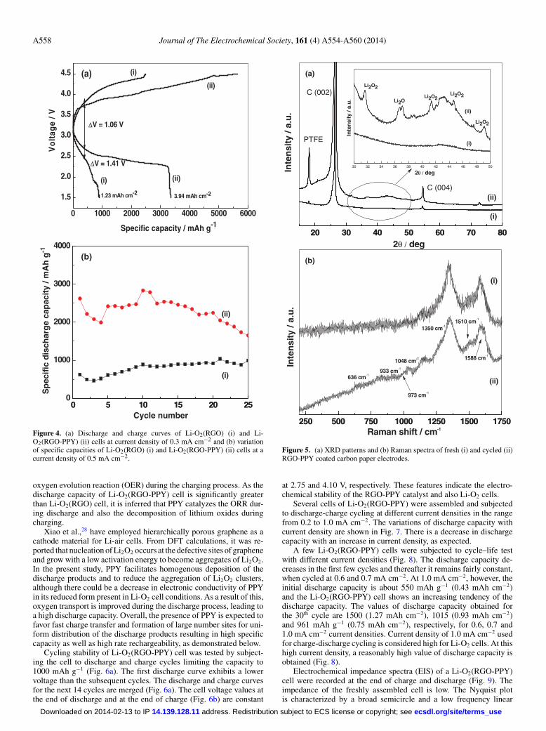
−) (reaction 2). Lithium superoxide undergoes another single-electron transfer reduction (reaction 3) forming lithium peroxide,which further undergoes two electron transfer reduction (reaction 4)resulting in the formation of the final reduction product, Li2O. Duringthe charging process, Li2O2 and Li2O are converted to O2 followingthe reverse steps of reactions 4, 3 and 2 in sequence. A Li-O2(RGO-PPY) cell was subjected to several charge-discharge cycles and thecycling was terminated when the cell reached discharged state. The O2
electrode was rinsed with acetone, air-dried and XRD pattern of the
electrode was recorded. XRD pattern of cycled electrode and freshelectrode are shown in Fig. 5a for comparison. A strong reflectionat 26.7◦ is attributed to (002) plane of carbon present in the elec-trode (Fig. 5a (i) and (ii)). The reflection at 18.2◦ is due to the PTFEbinder. The peak at 37.1◦ is due to Li2O and reflections at 31.6, 41.4◦,44.6, 49.1◦ are due to Li2O2 present in the cycled electrode (Fig. 5a(ii)). These reflections are absent in XRD pattern of the fresh elec-trode (Fig. 5a(i)). These result are in agreement with powder XRDand in situ differential electrochemical mass spectrometry studiesconfirming the formation of Li2O2 on discharge and its subsequentdecomposition on charging of Li-O2 cells.5 Superoxide is known to bereactive toward organic materials. In order to identify any degradationproducts of PPy by superoxide, Raman spectra of cycled and freshelectrodes were recorded and shown in Fig. 5b. The spectra are identi-cal with bands corresponding to π-conjugated structure (1588 cm−1),ring strectching vibrations (1350 cm−1), C-H in plane deformation(1048 cm−1), quinoid polaronic structure (973 cm−1), and bipolaronicstructure (933 cm−1).26 Thus, there are no indications of degradationof PPY by reaction of superoxide. Furthermore, cell failures are notobserved in the present study. It is considered that the reactivity ofO2
− toward the electrolyte and poypyrrole is neglibily small. Perhaps,O2
− is converted to Li2O2 in a fast step.It is interesting to observe that both Li-O2(RGO-PPY) and Li-
O2(RGO) cells exhibit electrochemical activity and provide reason-able values of discharge capacity (Fig. 4a and 4b). The performanceof Li-O2(RGO) cell is in conformity with the demonstration that thereduction of O2 resulting in the formation of Li2O2 takes place evenin the absence of a catalyst at the positive electrode of a Li-O2 cell.5
Mechanistically, the adsorption of O2 on the catalyst surface isexpected to be the primary step of oxygen reduction reaction (ORR).As both RGO and PPY possess large surface and edge defects, itis expected that the electrodes made of RGO and RGO-PPY arerich with defects facilitating adsorption O2. The adsorbed O2, thus,undergoes electron transfer in the presence of Li+ producing LiO2,Li2O2 and Li2O (reactions 2–4) during discharge of Li-O2(RGO) andLi-O2(RGO-PPY) cells. The reverse reactions occur resulting in
ecsdl.org/site/terms_use address. Redistribution subject to ECS license or copyright; see 14.139.128.11Downloaded on 2014-02-13 to IP
A558 Journal of The Electrochemical Society, 161 (4) A554-A560 (2014)
0 1000 2000 3000 4000 5000 6000
1.5
2.0
2.5
3.0
3.5
4.0
4.5
(ii)(i)
(ii)
ΔV = 1.41 V
3.94 mAh cm-21.23 mAh cm-2
ΔV = 1.06 V
(a) (i)
V
olt
age
/ V
Specific capacity / mAh g-1
0 5 10 15 20 250
1000
2000
3000
4000
0 5 10 15 20 25
Sp
ecif
ic d
isch
arg
e ca
pac
ity
/ mA
h g
-1
Cycle number
(b)
(ii)
(i)
Figure 4. (a) Discharge and charge curves of Li-O2(RGO) (i) and Li-O2(RGO-PPY) (ii) cells at current density of 0.3 mA cm−2 and (b) variationof specific capacities of Li-O2(RGO) (i) and Li-O2(RGO-PPY) (ii) cells at acurrent density of 0.5 mA cm−2.
oxygen evolution reaction (OER) during the charging process. As thedischarge capacity of Li-O2(RGO-PPY) cell is significantly greaterthan Li-O2(RGO) cell, it is inferred that PPY catalyzes the ORR dur-ing discharge and also the decomposition of lithium oxides duringcharging.
Xiao et al.,28 have employed hierarchically porous graphene as acathode material for Li-air cells. From DFT calculations, it was re-ported that nucleation of Li2O2 occurs at the defective sites of grapheneand grow with a low activation energy to become aggregates of Li2O2.In the present study, PPY facilitates homogenous deposition of thedischarge products and to reduce the aggregation of Li2O2 clusters,although there could be a decrease in electronic conductivity of PPYin its reduced form present in Li-O2 cell conditions. As a result of this,oxygen transport is improved during the discharge process, leading toa high discharge capacity. Overall, the presence of PPY is expected tofavor fast charge transfer and formation of large number sites for uni-form distribution of the discharge products resulting in high specificcapacity as well as high rate rechargeability, as demonstrated below.
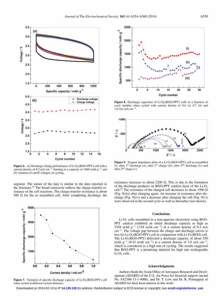
Cycling stability of Li-O2(RGO-PPY) cell was tested by subject-ing the cell to discharge and charge cycles limiting the capacity to1000 mAh g−1 (Fig. 6a). The first discharge curve exhibits a lowervoltage than the subsequent cycles. The discharge and charge curvesfor the next 14 cycles are merged (Fig. 6a). The cell voltage values atthe end of discharge and at the end of charge (Fig. 6b) are constant
250 500 750 1000 1250 1500 1750250 500 750 1000 1250 1500 1750Raman shift / cm-1
(b)
Inte
nsi
ty /
a.u
.(i)
636 cm-1
973 cm-1
1048 cm-1
933 cm-1
1350 cm-1
1588 cm-1
1510 cm-1
(ii)
20 30 40 50 60 70 8020 30 40 50 60 70 80
30 32 34 36 38 40 42 44 46 48 50
(ii)
(i)
C (002)
PTFE
(a)
Inte
nsi
ty /
a.u
.
2θ / deg
2θ / deg
C (004)
Li2O2
Li2O2
Li2O
Li2O2
Li2O2
Inte
nsi
ty /
a.u
. (ii)
(i)
Figure 5. (a) XRD patterns and (b) Raman spectra of fresh (i) and cycled (ii)RGO-PPY coated carbon paper electrodes.
at 2.75 and 4.10 V, respectively. These features indicate the electro-chemical stability of the RGO-PPY catalyst and also Li-O2 cells.
Several cells of Li-O2(RGO-PPY) were assembled and subjectedto discharge-charge cycling at different current densities in the rangefrom 0.2 to 1.0 mA cm−2. The variations of discharge capacity withcurrent density are shown in Fig. 7. There is a decrease in dischargecapacity with an increase in current density, as expected.
A few Li-O2(RGO-PPY) cells were subjected to cycle–life testwith different current densities (Fig. 8). The discharge capacity de-creases in the first few cycles and thereafter it remains fairly constant,when cycled at 0.6 and 0.7 mA cm−2. At 1.0 mA cm−2, however, theinitial discharge capacity is about 550 mAh g−1 (0.43 mAh cm−2)and the Li-O2(RGO-PPY) cell shows an increasing tendency of thedischarge capacity. The values of discharge capacity obtained forthe 30th cycle are 1500 (1.27 mAh cm−2), 1015 (0.93 mAh cm−2)and 961 mAh g−1 (0.75 mAh cm−2), respectively, for 0.6, 0.7 and1.0 mA cm−2 current densities. Current density of 1.0 mA cm−2 usedfor charge-discharge cycling is considered high for Li-O2 cells. At thishigh current density, a reasonably high value of discharge capacity isobtained (Fig. 8).
Electrochemical impedance spectra (EIS) of a Li-O2(RGO-PPY)cell were recorded at the end of charge and discharge (Fig. 9). Theimpedance of the freshly assembled cell is low. The Nyquist plotis characterized by a broad semicircle and a low frequency linear
ecsdl.org/site/terms_use address. Redistribution subject to ECS license or copyright; see 14.139.128.11Downloaded on 2014-02-13 to IP
Journal of The Electrochemical Society, 161 (4) A554-A560 (2014) A559
0 2 4 6 8 10 12 14 161.5
2.0
2.5
3.0
3.5
4.0
4.5
5.0
Vo
ltag
e / V
Cycle number
Discharge voltageCharge voltage
(b)
0 200 400 600 800 10001.5
2.0
2.5
3.0
3.5
4.0
4.5
Vo
ltag
e / V
Specific capacity / mAh g-1
(a)
Figure 6. (a) Discharge-charge performance of Li-O2(RGO-PPY) cell with acurrent density of 0.2 mA cm−2 limiting to a capacity of 1000 mAh g−1 and(b) variation of cutoff voltages on cycling.
segment. The nature of the data is similar to the data reported inthe literature.29 The broad semicircle reflects the charge-transfer re-sistance of the cell reactions. The charge-transfer resistance is about500 � for the as assembled cell. After completing discharge, the
0.0 0.2 0.4 0.6 0.8 1.0
1500
3000
4500
6000
0.0 0.2 0.4 0.6 0.8 1.0
Current density / mA cm-2
Sp
ecif
ic d
isch
arg
e ca
pac
ity
/ mA
h g
-1
Figure 7. Variation of specific discharge capacity of Li-O2(RGO-PPY) cellwhen cycled at different current densities.
0 5 10 15 20 25 30
500
1000
1500
2000
2500
(iii)
(ii)
Sp
ecif
ic d
isch
arg
e ca
pac
ity
/ mA
h g
-1
Cycle number
(i)
Figure 8. Discharge capacities of Li-O2(RGO-PPY) cells as a function ofcycle number when cycled with current density of 0.6 (i), 0.7 (ii) and1.0 (iii) mA cm−2.
0 500 1000 1500 2000 2500
-500
-1000
Z'' / Ω
(v)
(iv)
(iii)
(ii)
(i)
Z' /
Ω
Figure 9. Nyquist impedance plots of a Li-O2(RGO-PPY) cell as assembled(i), after 1st discharge (ii), after 1st charge (iii), after 2nd discharge (iv) andafter 2nd chage (v).
resistance increases to about 2200 �. This is due to the formationof the discharge products on RGO-PPY catalyst layer of the Li-O2
cell.28 The resistance of the charged cell decreases to about 1500 �(Fig. 9(iii)) after charging again. An increase in resistance after dis-charge (Fig. 9(iv)) and a decrease after charging the cell (Fig. 9(v))were observed in the second cycle as well as thereafter (not shown).
Conclusions
Li-O2 cells assembled in a non-aqueous electrolyte using RGO-PPY catalyst exhibited an initial discharge capacity as high as3358 mAh g−1 (3.94 mAh cm−2) at a current density of 0.3 mAcm−2. The voltage gap between the charge and discharge curves isless for Li-O2(RGO-PPY) cell in comparison with Li-O2(RGO) cell.The Li-O2(RGO-PPY) delivered a discharge capacity of about 550mAh g−1 (0.43 mAh cm−2) at a current density of 1.0 mA cm−2,which is considered as a high rate of cycling. The results suggestedthat RGO-PPY is a promising material for high rate rechargeableLi-O2 cells.
Acknowledgments
Authors thank the Asian Office of Aerospace Research and Devel-opment (AOARD) of the U.S. Air Force for financial support (awardNo. FA2386-13-1-4006), and Dr. T. Low and Dr. R. Ponnappan ofAOARD for their keen interest in this work.
ecsdl.org/site/terms_use address. Redistribution subject to ECS license or copyright; see 14.139.128.11Downloaded on 2014-02-13 to IP
A560 Journal of The Electrochemical Society, 161 (4) A554-A560 (2014)
References
1. K. M. Abraham and Z. Jiang, J. Electrochem. Soc., 143, 1 (1996).2. T. Ogasawara, A. Debart, M. Holzapfel, P. Novak, and P. G. Bruce, J. Am. Chem.
Soc., 128, 1390 (2006).3. Y. G Wang, L. Cheng, F. Li, H. M Xiong, and Y. Y Xia, Chem. Mater., 19, 2095
(2007).4. A. Debart, A. J. Paterson, J. Bao, and P. G. Bruce, Angew, Chem. Int. Ed., 47, 4521
(2008).5. A. Debart, J. Bao, G. Armstrong, and P. G. Bruce, J. Power Sources, 174, 1177
(2007).6. T. Zhang, N. Imanishi, Y. Shimonshi, A. Hirano, Y. Takeda, O. Yamamoto, and
N. Sammes, Chem. Comm., 46, 1661 (2010).7. A. K. Thapa, K. Saimen, and T. Ishihara, Electrochem. Solid-State Lett., 13, A165
(2010).8. H. Cheng and K. Scott, J. Power Sources, 195, 1370 (2010).9. Y. C Lu, Z. Xu, H. A. Gasteiger, S. Chen, K. Hamad-Schifferli, and Y. Shao-Horn,
J. Am. Chem. Soc., 132, 12170 (2010).10. L. Wang, X. Zhao, Y. Lu, M. Xu, D. Zhang, R. S. Ruoff, K. J. Stevenson, and
J. B. Goodenough, J. Electrochem. Soc., 158, A1379 (2011).11. Y. Li, J. Wang, X. Li, D. Geng, R. Li, and X. Sun, Chem. Comm., 47, 9438 (2011).12. E. Yoo and H. Zhou, ACS Nano, 5, 3020 (2011).13. C. Selvaraj, N. Munichandraiah, and L. G. Scanlon, J. Porphyrins Phthalocyanines,
16, 255 (2012).14. Y. Cui, Z. Wen, X. Liang, Y. Lu, J. Jin, M. Wu, and X. Wu, Energy Environ. Sci., 5,
7893 (2012).
15. A. K. Geim and K. S. Novoselov, Nature Mater., 6, 183 (2007).16. C. N. R. Rao, A. K. Sood, K. S. Subrahmanyam, and A. Govindaraj, Angew. Chem.
Int. Ed., 48, 7752 (2009).17. E. Antolini, Appl. Catal. B: Env., 123-124, 52 (2012).18. S. Bose, T. Kuila, A. K. Mishra, R. Rajasekar, N. H. Kim, and J. H. Lee, J. Mater.
Chem., 22, 767 (2012).19. M. Liang and L. Zhi, J. Mater. Chem., 19, 5871 (2009).20. W. S. Hummers and R. E. Offeman, J. Am. Chem. Soc., 80, 1339
(1958).21. Surender Kumar, C. Selvaraj, N. Munichandraiah, and L. G. Scanlon, RSC Adv., 3,
21706 (2013).22. J. Yang, C. Zhang, L. Sun, N. Zhao, and X. Cheng, Mater. Chem. Phys., 129, 270
(2011).23. S. Dubin, S. Gilje, K. Wang, V. C. Tung, K. Cha, A. S. Hall, J. Farrar, R. Varshneya,
Y. Yang, and R. B. Kaner, ACS Nano, 4, 2845 (2010).24. S. Stankovich, D. A. Dikin, R. D. Piner, K. A. Kohlhaas, A. Kleinhammes, Y. Jia,
Y. Wu, S. T. Nguyen, and R. S. Ruoff, Carbon, 45, 1558 (2007).25. C. Zhu, S. Guo, Y. Fang, and S. Dong, ACS Nano, 4, 2429 (2010).26. S. Biswas and L. T. Drzal, Chem. Mater., 22, 5667 (2010).27. C. O. Laoire, S. Mukherjee, and K. M. Abraham, J. Phys. Chem. C., 113, 20127
(2009).28. J. Xiao, M. Donghai, X. Li, W. Xu, D. Wang, L. G. Gordon, D. B. Wendy,
Z. Nie, V. S. Laxmikant, A. A. Ilhan, J. Liu, and J. G. Zhang, Nano Lett., 11, 5071(2011).
29. M. Eswaran, N. Munichandraiah, and L. G. Scanlon, Electrochem. Solid-State Lett.,9, A121 (2010).
ecsdl.org/site/terms_use address. Redistribution subject to ECS license or copyright; see 14.139.128.11Downloaded on 2014-02-13 to IP
Copyright © 2022 FDOKUMEN


![Synthesis and Structure of trans-[O2(Im)4Tc]Cl•2H,O, trans-[O2(1-meIm1)4Tc]Cl•3H2O and Related Compounds](https://static.fdokumen.com/doc/165x107/63398ee975188717130476f6/synthesis-and-structure-of-trans-o2im4tccl2ho-trans-o21-meim14tccl3h2o.jpg)