Bosch LSU 4.2 Wideband O2 Sensor Testing (2001 ... - Instructables
15
instructables Bosch LSU 4.2 Wideband O2 Sensor Testing (2001 Skoda Octavia 1.6 (AVU)) by Koncrete First, a disclaimer The reader should be aware that I am not a professional and my knowledge of wideband sensors is limited. This is borne out in the slight discrepancies between my results and what is typically expected. While the fix and testing worked, it does not look perfect. With that out of the way, lets continue. Briefly, some background Wideband O2 sensors (also known as air-fuel ratio sensors or AFR sensors) were created to allow faster monitoring and more precise control of the air/fuel ratio of internal combustion engines over a much wider range of air/fuel ratios than traditional sensors. They serve this purpose well, however with this advantage comes the disadvantage of complexity. The sensor (Images 1 to 4) consists of a heating element, a traditional zirconia type switching sensor (known as a Nernst cell) and an oxygen ion pumping cell. The general operating principle is not too much different to how the traditional sensor behaves. The Nernst cell generates a voltage due to the reaction with oxygen in the exhaust gas and the oxygen pump compares this Nernst voltage with a reference of 450 mV and tries to equalise the Nernst voltage. The current required to balance these voltages directly relates to the quantity of oxygen in the exhaust gas itself. As opposed to the simple switching response of rich or lean given by a traditional sensor. The control of the heater circuit in wideband sensors is more intricate than for traditional sensors. The heat at the sensor has to be maintained within a specified range and the heater is usually controlled using PWM. The heater failing in a wideband sensor is equivalent to the whole sensor failing. Specifics of this particular type of sensor are available in Bosch document #Y 258 K01 005-000e and datasheets for the products. Layout of the sensors Figure 5 shows the general arrangement of oxygen sensors in a generic single bank engine (banks are numbered with a B prefix, in this case, all sensors are under B1). (B1)S1 is the wideband sensor, it is the pre-catlayst sensor. (B1)S2 is a conventional narrowband sensor, it is the post-catalyst sensor. Figure 6 shows a section of the wiring diagram for this particular car, with the sensors marked. Noted problems with the car The car showed periodic check engine lights during the previous year before it was worked on. These were checked using generic OBD2 and came up as a P0130 (O2 Sensor Circuit Malfunction B1S1). Freeze frame data didn't show too much: Open loop Load: 35% Coolant temp: 14 °C Short term fuel trim: 0 Long term fuel trim: Bosch LSU 4.2 Wideband O2 Sensor Testing (2001 Skoda Octavia 1.6 (AVU)): Page 1
-
Upload
khangminh22 -
Category
Documents
-
view
1 -
download
0
Transcript of Bosch LSU 4.2 Wideband O2 Sensor Testing (2001 ... - Instructables

instructables
Bosch LSU 4.2 Wideband O2 Sensor Testing (2001 Skoda Octavia 1.6 (AVU))
by Koncrete
First, a disclaimerThe reader should be aware that I am not aprofessional and my knowledge of wideband sensorsis limited. This is borne out in the slight discrepanciesbetween my results and what is typically expected.While the fix and testing worked, it does not lookperfect.
With that out of the way, lets continue.
Briefly, some backgroundWideband O2 sensors (also known as air-fuel ratiosensors or AFR sensors) were created to allow fastermonitoring and more precise control of the air/fuelratio of internal combustion engines over a muchwider range of air/fuel ratios than traditional sensors.They serve this purpose well, however with thisadvantage comes the disadvantage of complexity.
The sensor (Images 1 to 4) consists of a heatingelement, a traditional zirconia type switching sensor(known as a Nernst cell) and an oxygen ion pumpingcell. The general operating principle is not too muchdifferent to how the traditional sensor behaves. TheNernst cell generates a voltage due to the reactionwith oxygen in the exhaust gas and the oxygen pumpcompares this Nernst voltage with a reference of 450mV and tries to equalise the Nernst voltage. Thecurrent required to balance these voltages directlyrelates to the quantity of oxygen in the exhaust gasitself. As opposed to the simple switching response ofrich or lean given by a traditional sensor.
The control of the heater circuit in wideband sensorsis more intricate than for traditional sensors. The heatat the sensor has to be maintained within a specified
range and the heater is usually controlled usingPWM. The heater failing in a wideband sensor isequivalent to the whole sensor failing.
Specifics of this particular type of sensor areavailable in Bosch document #Y 258 K01 005-000eand datasheets for the products.
Layout of the sensorsFigure 5 shows the general arrangement of oxygensensors in a generic single bank engine (banks arenumbered with a B prefix, in this case, all sensors areunder B1). (B1)S1 is the wideband sensor, it is thepre-catlayst sensor. (B1)S2 is a conventionalnarrowband sensor, it is the post-catalyst sensor.
Figure 6 shows a section of the wiring diagram forthis particular car, with the sensors marked.
Noted problems with the carThe car showed periodic check engine lights duringthe previous year before it was worked on. Thesewere checked using generic OBD2 and came up as aP0130 (O2 Sensor Circuit Malfunction B1S1).
Freeze frame data didn't show too much:
Open loop
Load: 35%
Coolant temp: 14 °C
Short term fuel trim: 0
Long term fuel trim:
Bosch LSU 4.2 Wideband O2 Sensor Testing (2001 Skoda Octavia 1.6 (AVU)): Page 1
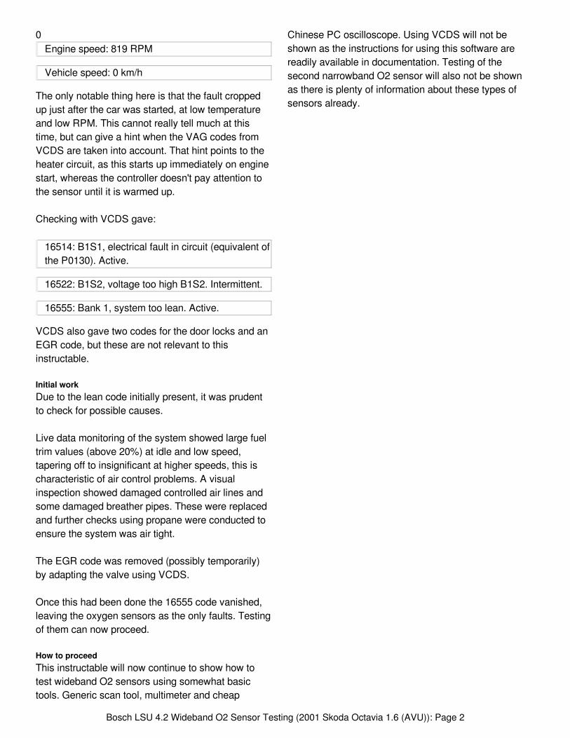
0Engine speed: 819 RPM
Vehicle speed: 0 km/h
The only notable thing here is that the fault croppedup just after the car was started, at low temperatureand low RPM. This cannot really tell much at thistime, but can give a hint when the VAG codes fromVCDS are taken into account. That hint points to theheater circuit, as this starts up immediately on enginestart, whereas the controller doesn't pay attention tothe sensor until it is warmed up.
Checking with VCDS gave:
16514: B1S1, electrical fault in circuit (equivalent ofthe P0130). Active.
16522: B1S2, voltage too high B1S2. Intermittent.
16555: Bank 1, system too lean. Active.
VCDS also gave two codes for the door locks and anEGR code, but these are not relevant to thisinstructable.
Initial workDue to the lean code initially present, it was prudentto check for possible causes.
Live data monitoring of the system showed large fueltrim values (above 20%) at idle and low speed,tapering off to insignificant at higher speeds, this ischaracteristic of air control problems. A visualinspection showed damaged controlled air lines andsome damaged breather pipes. These were replacedand further checks using propane were conducted toensure the system was air tight.
The EGR code was removed (possibly temporarily)by adapting the valve using VCDS.
Once this had been done the 16555 code vanished,leaving the oxygen sensors as the only faults. Testingof them can now proceed.
How to proceedThis instructable will now continue to show how totest wideband O2 sensors using somewhat basictools. Generic scan tool, multimeter and cheap
Chinese PC oscilloscope. Using VCDS will not beshown as the instructions for using this software arereadily available in documentation. Testing of thesecond narrowband O2 sensor will also not be shownas there is plenty of information about these types ofsensors already.
Bosch LSU 4.2 Wideband O2 Sensor Testing (2001 Skoda Octavia 1.6 (AVU)): Page 2

1. Modified from an image by Michael Handrich.Original hosted by Wikimedia.
1. 6 pin connector.2. Wideband O2 sensor
1
1
2
Bosch LSU 4.2 Wideband O2 Sensor Testing (2001 Skoda Octavia 1.6 (AVU)): Page 3

1. B1S1. Bank 1, sensor 1.2. B1S2. Bank 1, sensor 2.3. Modified from an image by Stefan-Xp.Original hosted by Wikimedia.
1. B1S1. Bank 1, sensor 1.Pre catalyst, wideband sensor.2. B1S2. Bank 1, sensor 2.Post catalyst, narrowband sensor.
Step 1: Bosch LSU Wideband AFR Sensor Testing - Scan Tool and Multimeter
Using a generic scan toolIn this case the tool used is an AUTEL VAG505 (figure 1), a pretty poorly equipped VAG specific budget scan tool,however it has generic OBD2 live data capabilities. In VAG mode it can find VAG specific fault codes but oftenmisses some and cannot do much else.
All of these tests require the engine to be running and generally at operating temperature. The scan tool should beplugged in of course and monitoring at least the wideband O2 sensor and the Short Term Fuel Trim (STFT).However monitoring Long Term Fuel Trim (LTFT), equivalence ratio and the other O2 sensor can help providesome additional framing for the data received.
Figure 2 shows a sample of the wiring diagram for this car with the sensors marked.
Tests manipulating the throttle
Performing a snap throttle test is a very quick and easy way to test the response of an O2 sensor. With awideband sensor, the reading will be essentially the reverse of a narrowband sensor.
A theoretical waveform for this test is shown in figure 3. On the initial application of full throttle the reading shoulddrop low followed by shooting immediately high once the throttle is released. It will then level off to what it wasbefore the snap throttle test. It is a good idea to do a few of these tests to ensure things are as they should be.
The initial drop is due to the sudden influx of fuel into the engine, the sudden rise is due to the fuel cut.
Tests manipulating the air system
These tests should be performed while the engine is at idle.
Force a lean condition
1 2
3
1 2
Bosch LSU 4.2 Wideband O2 Sensor Testing (2001 Skoda Octavia 1.6 (AVU)): Page 4

The first test involves causing an artificial lean condition (more air than expected). This can be accomplished byunplugging a vacuum hose.
This should result in an immediate change in engine tone, a loud sucking noise from the unplugged hose and thescan tool registering changes on the STFT and wideband O2 sensor. The STFT should show a large increase invalue from its usual value. This is due to the computer trying to fix the fuel trim by adding more fuel. The widebandO2 sensor (as opposed to the narrowband type) should increase in value.
Running the engine like this (if it doesn't stall) will eventually result in the LTFT increasing in an attempt to catch upto the STFT. It may or may not (depending on the size of the hose removed) eventually level off and the STFT mayreturn to zero.
Once complete, reconnect the air hose and watch for the opposite happening, the STFT decreasing, the widebandO2 sensor decreasing in value and eventually the LTFT catching up and them all levelling off.
Force a rich condition
The second test involves causing an artificial rich condition (more hydrocarbons than expected). This is oftenaccomplished by squirting propane into the air intake. However some people have used starter spray or otherflammable substance, however propane is safer and easier.
This should result in an immediate change in engine sound and the scan tool registering changes on the STFT andwideband O2 sensor. The STFT should show a large decrease in value from its usual value. This is due to thecomputer trying to fix the fuel trim by subtracting fuel. The wideband O2 sensor (as opposed to the narrowbandtype) should decrease in value.
Running the engine like this will eventually result in the LTFT decreasing in an attempt to catch up to the STFT. Itmay or may not (depending on the size of the hose removed) eventually level off and the STFT may return to zero.
Once complete, discontinue the application of your chosen hydrocarbon and watch for the opposite happening, theSTFT increasing, the wideband O2 sensor increasing in value and eventually the LTFT catching up and them alllevelling off.
Other substances to inject
It is possible to inject other non-hydrocarbon substances into the inlet to perform these tests, however there issome disagreement on what will happen and what actually does happen depending on the source of thesubstance, the purity of the substance and the place of application. For example: using helium, carbon dioxide,etc. As these substances are often harder to get at a decent purity, and more costly, it is better to usehydrocarbons, unless there is a compelling reason not to.
Multimeter testsUsing a multimeter it is possible to test the resistance between the various pins of the wideband O2 sensor. This isa very useful way to quickly see if the sensor itself is electrically sound.
Resistance tests
The first check to perform is to check the resistance between pins 3 and 4 (heater supply and ground), this shouldbe in the range of 2 to 8 ohms at a temperature of 20 C.
Bosch LSU 4.2 Wideband O2 Sensor Testing (2001 Skoda Octavia 1.6 (AVU)): Page 5

The next check is to test the resistance between heater pins and metal body of the sensor. This should read openor at least very high resistance (1 Mohm or more).
The next check is to test the resistances between heater pins and other pins. All of these checks should read openor at least very high resistance (1 Mohm or more).
Figure 2 shows the Skoda wiring diagram section for the O2 sensors, the wideband sensor is to the left, labelledB1S1. Figure 4 shows the sensor side connector with pins numbered and their circuit pairings in like colours.Figure 5 shows the measured resistance values between heater pins (3 and 4) and the other pins in the sensor, forthis particular car.
It can be seen from figure 5 that the heater coil resistance is 3.5 ohms, meaning the heater coil itself is fine. Therewas open circuit measured between the heater and the body of the sensor, so this is again fine. However it canalso be seen that there is a low resistance between the heater circuit pins and pins 1 & 5 (Nernst cell). This on itsown is reason to replace the sensor and probably the cause of the fault.
It is also possible to measure the trimming resistor (pins 2 and 6), however this has a large range of possiblevalues (30-300 ohms) and without this information from the manufacturer it is hard to be sure what it is meant tobe. Typically, however, it is reported to be around 100 ohm.
Voltage tests
With the engine running and the sensor unplugged, the voltage between harness side pins 1 and 5 should staywithin the range of 0.4 to 0.5 V. This is the reference voltage of the Nernst cell, this varies when plugged in andrunning however it is always trying to be pulled to 0.45 V.
1. OBD2 connector.2. Device connector
1. Bank 1, sensor 1. Pre-catalyst, heated, wideband O2 sensor.2. Bank 1, sensor 2. Post-catalyst, heated, narrowband O2 sensor.
1
2
1 2
Bosch LSU 4.2 Wideband O2 Sensor Testing (2001 Skoda Octavia 1.6 (AVU)): Page 6

1. This is just a typical snap throttle test reaction. This is not necessarily exactlylike what will be seen on an individual vehicle with a working sensor, but it willbe something like this.2. Stoichiometric value for this particular Skoda, other manufacturers vary.
1. Pins:6 4 25 3 1
1&5: Nernst (measurement) cell2&6: Pump cell and calibration resistor3&4: Heater circuit
1. This is a problem. All but pins 3 to 4 should be open circuit orvery high resistance.2. This is a problem. All but pins 3 to 4 should be open circuit orvery high resistance.3. Pins 3 to 4 should be around 3.5 ohms at 20 C. This sensor isperfect in this regard.
1
21
1 23
Bosch LSU 4.2 Wideband O2 Sensor Testing (2001 Skoda Octavia 1.6 (AVU)): Page 7

Step 2: Bosch LSU Wideband O2 Sensor Testing - Oscilloscope Set Up
Locating the connectorsOn this model of car the connectors for both O2sensors are in a small black plastic housing under thepassenger side seat (right hand side). This housing isremoved by unscrewing two plastic nuts, the housingand connectors then come away from the floor of thecar and can be removed from the housing andopened up.
Figure 1 shows the removed and opened connectors.The left hand connector is the sensor connector, andthe other is the harness connector.
Connecting breakout leadsIn order to monitor the sensor's function the sensorhas to be operating and the engine has to be running.It is possible to backprobe all of the pins, but thiswould not be the safest nor easiest way. It is mucheasier to use a breakout lead set. These are availablefor purchase, or they can be made yourself. I mademy own, these are show in in figure 2. Bear in mindthat using breakout leads may lead to issues for verysensitive sensor circuits, especially when usinghomemade ones..
Connect each pin and socket one by one like for like.Meaning that you connect pin one in the sensorconnector to pin one in the harness connector. Dothis for each pin.
Connecting the oscilloscopeThe connection scheme for these tests is shown infigure 3. Figures 4 and 5 show the leads connectedup.
The first connection is the Nernst cell connection,pins 1 and 5. This measures the traditional zirconiasensor that is the core of the wideband O2 sensor.
The second connection handles the trimming andpump cell current, this is the part of the widebandsensor which attempts to level the Nernst cell at 450mV, and the part that gives the sensor its outputvalue.
The third connection measures the heater voltage,with the fourth a current clamp measuring the heatercurrent.
1. Sensor side connector.2. Harness side connector.
1. Spade socket, 2.8 mm2. Spade plug, 2.8 mm3. Soldered 4 mm banana plug4. Salvaged wire
scope connections.JPG
1 2
1
2
3
4
1
Bosch LSU 4.2 Wideband O2 Sensor Testing (2001 Skoda Octavia 1.6 (AVU)): Page 8

1. Stud for connector cover attachment.2. Sensor and harness connectors. These areconnected like for like, using breakout leads.3. Oscilloscope connections for monitoring.4. Current clamp around heater supply wire.
Step 3: Bosch LSU Wideband O2 Sensor Testing - Fault Scope Readings
Overview of the testingOnce the scope is wired up correctly the test can begin. The general pattern of the testing is as sugh:
1. Startup2. Warmup3. Running at idle4. Snap throttle tests
2
34
Bosch LSU 4.2 Wideband O2 Sensor Testing (2001 Skoda Octavia 1.6 (AVU)): Page 9

5. Shutdown
In addition to these it is possible to do some runs at certain rev ranges, but this is not necessary for this test.
The channels used in these images are as such:
1. Nernst cell2. Pump cell3. Heater voltage4. Heater current
Please forgive the measurements on the bottom of the scope screen, I was experimenting with new equipmentand didn't think to clear them before making these screen shots.
Please also forgive the polarity of some of the readings. They can still be read, but it should be noted that theheater test cable is wired up incorrectly and consequently shows negative volts.
Startup (Figures 1 & 2)
On startup, operation of the heater circuit seems to behave as expected.
The heater immediately starts to operate using PWM control. Its initial starting maximum voltage is dictated by thetechnical documentation, and in this case is about 11 V. There is a clear ramping up from this initial voltage to themaximum voltage and then sustaining PWM control of the heater voltage.
The heater is also drawing current as expected, although it is perhaps a little low (should be about 4 A, is about 2A). Although it is hard to be certain due to the low quality current clamp in use.
The Nernst and pump cells are not doing much at this early stage.
Cold engine running (Figure 3)
The engine is still cold, but the sensor and heater are up to temperature here and so it can start to function.Immediately it is notable that there is some problem with the measurement cell waveform.
The measurement cell appears to be mirroring what the heater voltage is doing. This seems to indicate thatvoltage is spilling over from the heater circuit into the measurement cell. This on its own would be cause to replacethe sensor (after checking connections again ... a few times :) )
The heater circuit, however, appears to be functioning as it should. It appears to be operating at about 10 Hz,which is above the minimum required for this type of sensor, no maximum is specified.
Hot engine running (Figure 4)
At this point the engine speed slows, the engine is up to working temperature and the situation is much worse thanbefore. The heater is still running as it should, but the leaked voltage is of course affecting the pump cell's attemptsto keep the measurement cell at 450 mV.
Snap throttle test (Figure 5)
Bosch LSU 4.2 Wideband O2 Sensor Testing (2001 Skoda Octavia 1.6 (AVU)): Page 10

This test is superfluous, but fitting with the belt and braces approach. A quick snap throttle is performed and thewaveforms monitored. The test happens at about 2 seconds into the frame and there is a response, but it is sosmall, it can't really make any difference to the hugely incorrect information being sent to the ECU.
Stopping (Figure 6)
On engine stop the heater immediately shuts off, the measurement ceases and voltages start to level off to normal.
Test conclusionThe sensor is broken. It needs to be replaced. For now I do not perform any wiring checks as the sensor will bereplaced either way and if any more problems manifest, they can be dealt with once the new sensor is installedand tested.
Bosch LSU 4.2 Wideband O2 Sensor Testing (2001 Skoda Octavia 1.6 (AVU)): Page 11

Step 4: Bosch LSU Wideband O2 Sensor Testing - After Fix Scope Readings
Overview of the testingOnce the scope is wired up correctly the test can begin. The general pattern of the testing is as sugh:
1. Startup2. Warmup3. Running at idle4. Snap throttle tests5. Shutdown
In addition to these it is possible to do some runs at certain rev ranges, but this is not necessary for this test. Thechannels used in these images are as such:
1. Nernst cell2. Pump cell3. Heater voltage4. Heater current
Please forgive the measurements on the bottom of the scope screen, I was still experimenting with this newequipment and didn't think to clear them before making these screen shots.
Please also forgive the polarity of some of the readings. They can still be read, but it should be noted that all of thetest cables are wired up incorrectly and consequently show negative volts.
Please also forgive the poor resolution in the heater current trace in figures 1 - 3, this is changed in figure 4onwards.
Startup (Figures 1 & 2)
On startup, operation of the heater circuit behaves as it should. The PWM control starts off at the initial maximumand ramps until it reaches the maximum allowed voltage. The current appears to be around 2.5 - 3 A, this is a little
Bosch LSU 4.2 Wideband O2 Sensor Testing (2001 Skoda Octavia 1.6 (AVU)): Page 12

low (due to the current clamp I'll wager) and also a little hard to see properly due to the resolution of the trace(sorry).
The Nernst and pump cells are not doing anything at this early stage.
Cold engine running (Figure 3)
This frame is where the fault in the old sensor was first noticed and appears to not be present here.
The engine is still cold, but the sensor and heater are up to temperature here and so it can start to function. Theheater is operating at full voltage at about 10 Hz, with maybe a 50% duty cycle. There is no crossover betweenheater circuit and other circuits, which seems to suggest that the fault was with the sensor not with wiring.
Hot engine running (Figure 4)
Once the engine is up to temperature the engine speed slows and the system is in full closed loop. Something thatdidn't happen with the faulty sensor.
This is where I notice a behaviour that doesn't fit with what I have researched about the operation of thesesensors. The Nernst cell appears to react to something in the exhaust stream with the pump cell reacting to whatthe Nernst cell does. I am not concerned as of now as everything is running smoothly. Although I am concernedabout possible leakage between the second O2 sensor (post cat, B1S2).
Snap throttle test (Figures 5 & 6)
A couple of snap throttle tests are performed. Both show a response roughly expected according todocumentation. However this response is in the Nernst cell (it appears backwards due to the connection of thescope). The measurement cell also reacts to what happens as is expected.
This instantaneous reaction to the snap throttle tests leaves me with little doubt that the reaction is a genuine onesensed by the Nernst cell, and not crossover from the second O2 circuit.
Stopping (Figure 7)
On engine stop the heater immediately shuts off, the measurement ceases and voltages start to level off.
Test conclusionThe sensor is clearly functioning properly, the lack of fault codes or pending codes logged shows that to be thecase and the traces of the signals generally shows that to be the case. However the obvious Nernst cell reactionsare against what I have understood to be expected. This could be a quirk of the VAG method of using widebandsensors. For final confirmation running the requisite O2 sensor tests in VCDS shows them to be functioningperfectly and the car passed its emissions and mandatory checks.
Bosch LSU 4.2 Wideband O2 Sensor Testing (2001 Skoda Octavia 1.6 (AVU)): Page 13

Bosch LSU 4.2 Wideband O2 Sensor Testing (2001 Skoda Octavia 1.6 (AVU)): Page 14

Step 5: Conclusion
The wideband O2 sensor of this car had degradedover time (the sensor had not been changed in the lifeof the car) and thus needed replacement. While theheater circuit itself was functioning fine, the leakagebetween heater circuit and Nernst cell was causingproblems.
Replacing the sensor cleared the codes and the carpassed its mandatory tests.
Doing this task made me realise how much there isstill to learn and know about wideband O2 sensors.Their complexity and lack of uniformity in theautomotive world makes them cumbersome to work
with and leaves doubts in the amateur's mind aboutthe work done and the diagnosis of the fault.
It seems wideband sensors are starting to fall out offavour with VAG at least, this is probably due to thiscomplexity.
All in all, this was a successful job, but work needsdoing on the theory and knowledge, on my part. Assuch, this instructable will likely be updated as newinformation comes my way and I make anycorrections that need making.
Bosch LSU 4.2 Wideband O2 Sensor Testing (2001 Skoda Octavia 1.6 (AVU)): Page 15