Observed Hurricane Wind Speed Asymmetries and Relationships to Motion and Environmental Shear
Upload
khangminh22Category
view
2download
0
Journal of Aerospace Technology and
Management
ISSN: 1948-9648
Instituto de Aeronáutica e Espaço
Brasil
Silva, Maurício G.; Gamarra, Victor O.R.; Koldaev, Vitor
Control of Reynolds number in a high speed wind tunnel
Journal of Aerospace Technology and Management, vol. 1, núm. 1, enero-junio, 2009, pp. 69-77
Instituto de Aeronáutica e Espaço
São Paulo, Brasil
Available in: http://www.redalyc.org/articulo.oa?id=309428885010
How to cite
Complete issue
More information about this article
Journal's homepage in redalyc.org
Scientific Information System
Network of Scientific Journals from Latin America, the Caribbean, Spain and Portugal
Non-profit academic project, developed under the open access initiative

Maurício G. Silva *Institute of Aeronautics and Space
Sao José dos Campos - [email protected]
Victor O.R. GamarraPaulista State University
Guaratinguetá - [email protected]
Vitor KoldaevInstitute of Aeronautics and Space
Sao José dos Campos - [email protected]
*author for correspondence
LIST OF SYMBOLS
Control of Reynolds number in ahigh speed wind tunnel
Abstract: A conceptual control model for the Reynolds number test based onisentropic relations was establishedfor the supersonic wind tunnel. Comparísonofthe system response ofthe model simulation andthe actualwindtunnel test datawas made lo design the control system. Two controllers were defined: the first onewas based on the stagnation pressure al the settlíng chamber; the second wasbased on the relaiion between stagnationpressure and temperature al the settlíngchamber which represents the Reynolds number specified [or the test. ASIMULIN.f(b block diagram code was used lo salve the mathematical modelconsístíng of mass and energy conservation equations. Performance of thesupersonic wind tunnel usíng a PI (proportional-plus-integral) controller wasfound to be scuisfactory. as confirmedby the results.Key Words: Blowdown wind tunnel, Pressure control, Mach number control,Reynolds numbercontrol.
Another restriction is the duration ofthe tests (run time).At a given Mach number, it is sometimes required tomaximize the test duration by running the tunnel at thelowest possible stagnation pressure but still maintainingsupersonic flow conditions. However, it is important toconsider the undesirable variation of Reynolds number inthe test section during a runo Therefore, the best choicefor the stagnation pressure and temperature at a givenMach number cannot be the best choice for the Reynoldsnumber. Due to the conflicting interrelation between theseparameters it is very difficult to reproduce to estimate,theoretically, the best test configuration experimentally in
There are many parameters that characterize a blowdownSupersonic Wind Tunnel (SWT) such as the test sectiondimensions, operating characteristics (Reynolds number xMach number), general capabilities of the facility (Machnumber range, maximum stagnation pressure) and so on.Many types of tests simulated in a high-speed wind tunnelare sensitive in various degrees to the errors in Mach andReynolds number. For example, one standard task certainlyis the measurement ofaerodynamic forces and moments. Inthis kind oftest, the formation ofshock waves inside thetestsection is expected due to the presence ofthe model. Thesewaves can reflect offthe walls, andmay cause a detrimentaleffect on the measurement of forces and pressures on thetested model. Since the angle of reflection is related to theMach number (pope and Goin, 1965), the choice of modelsize is a function of the Mach number in the test section.
DE(s)
hK,J;Mmpr
ReSWT
tTUvVepy
JiT
Subscript1d
difexit
O
Received: 23/03109Accepted: 20105109
Cross section AreaDischarge coefficientGas sizing coefficientSpecific heat (constantpressure)Specific heat (constantvolume)Test section diameterErrorSpecific EnlhalpyIntegral controller gainProportional controller gainMachnumberMass flowPressureRecovery factorReynolds numberSupersonic Wind TurmelTimeStagnation TemperatureInternal energyVelocityVolumeValve opening positionDensitySpecific heat ratioViscosityStatic Temperature
In front of shockDesired conditionDiffuserExit of diffuserSettling chamber
m's/m
JlkgK
JlkgK
mPaJlkg
kg/sPa
sKJmisM'degkg/m"
kg/sK
tT
TSv
INTRODUCTION
Throat of nozzleStorage tankTest sectionValve
Journal ofAerospace Technology and Management V. 1, n. 1, Jan. - Jun. 2009 69
Silva, M.G .; Gamarra, V.O.R.; Koldaev, V.
aeronautical components. SO, it is important (stagnationpressure, geometrical configuration of nozzles anddiffuser) before each experimental testrun,
In this context, a non-linear mathematical model wasdeveloped to analyze the open-loop system characteristicsas well as for the controller designo The model for SWT wasbased on the mathematical model proposed by Fung (1987).Each module of SWT is formulated as an isentropicsubsystem.
where Pr is the storage tank air density, m, is the mass effluxthrough the valve v,: and is the storage tank volume. Thesubscript "T' refers to the storage tank. By assuming theenergy loss through the valve is negligibly small, theinternal energy change in the slorage tank is equal lo theenthalpy plus the kinetic energy through the valve.Therefore:
(2)
Settling Chamber
(3)
(5)
dPr = _( YR TT)n1dt V
T,.
The quotienty=c/cv is the specific heat ratio andR is the gasconstant. The valve characteristics are described in FisherControls Company (1984), by the manufacturero The massflow at different valve positions is given by:
. = 2.295810 -' e rs · (27 IJ~pJm i' rz: g r r SIn .
,j I T PT (4)
where [.f is the storage tank air internal energy, h; is thespecific enthalpy of the air through the valve and v, is thevelocity of the air through the valve. In terms of thestagnation pressure, Eq. (2) can bewritten (Fung, 1987):
The second control volume is the settling chamber. Airflows into the settling chamber from the control valveand goes through the convergent-divergent nozzle tothe test section. The energy entering the settlingchamber volume with mass flow m, minus the energyexiting through the nozzle with mass flow m, is equalto the internal energy rate in the settling chamber.Therefore, the relation of energy conservation for thesettlingchamber is:
where Cg is the "gas sizing coefficient", Note that,Cg~Cg(IJ), where IJ is the valve opening position. Thevariables Pr and Pr are the therrnodynamic properties(temperature and pressure) ofthe air into the storage tank.M' is the pressure difference across the valve. It is assumedthat !1P=Pr-Po, where P¿ is the stagnation pressure at thesettling chamber.
DlFfVSER
nsrMCTION
AIRSlJPPl.Y lolOOO.(UP TO ~O~1
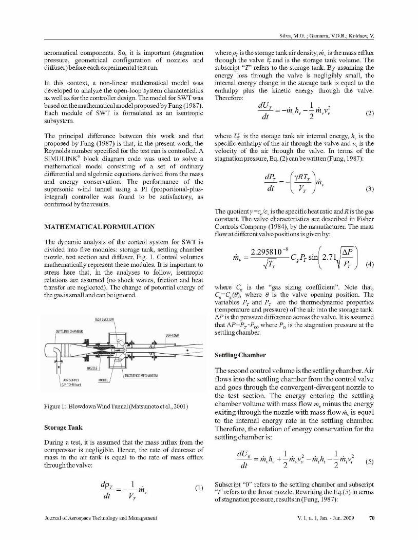
The dynamic analysis of the control system for SWT isdivided into five modules: storage tank, settling chambernozzle, test section and diffuser, Fig. 1. Control volurnesmathematically represent these modules. It is important tostress here that, in the analyses to follow, isentropicrelations are assurned (no shock waves, friction and heattransfer are neglected). The change of potential energy ofthe gas is small and can be ignored.
The principal difference between this work and thatproposed by Fung (1987) is that, in the present work, theReynolds number specified for the test run is controlled. ASIMULINK® block diagram code was used to solve amathematical model consisting of a set of ordinarydifferential and algebraic equations derived from the massand energy conservation. The performance of thesupersonic wind tunnel using a PI (proportional-plusintegral) controller was found to be satisfactory, asconfirmed bytheresults.
Figure 1: Blowdown Wind Tunnel (Matsumoto et al., 2001)
Storage Tank
During a test, it is assurned that the mass influx from thecompressor is negligible, Hence, the rate of decrease ofmass in the air tank is equal to the rate of mass effluxthrough the valve:
MATHEMATICALFORMULATION
do ¡ l .--=--m
dt VT '
(1)Subscript "O" refers lo the settling chamber and subscript"t" refers to the throat nozzle. Rewriting the Eq.(5) in termsofstagnation pressure, results in (Fung, 1987):
Journal ofAerospace Teclmology and Management V. 1, n. 1, Jan. - Jun. 2009 70

Control ofReynolds number in a high speed wind tunnel
The flow is without heat transfer. In this context, it ispossibleto rewrite Eq.(6):
Nozzle
dPo = (ep Ji)rmT - ti¡ T )dt ' JI ~' T 1 0e , o
dPu =(YRTT)rm - m)dt JI ~ , I
o
(6)
(7)
tunnel test section will be compressed and slowed down inthe converging section ofthe diffuser, will pass through thesecond throat at a speed considerably below that of the testsection, will begin to speed back up in the diverging portionof the diffuser, and will establish a normal shock in thediverging portion of the diffuser at a Mach numberconsiderably below the test section Mach number, and witha correspondingly smaller loss. The design of the secondthroat provides the required position of shock wave at thedivergent portion of nozzle. In order to estimate the rontime, the movement of the shock wave at the diffuser isconsidered, The test ron simulation is analyzed while theshock wave position is greater than the second throatposition,
The nozzle of the supersonic wind tunnel is axisymmetric,variable-geometry with converging-diverging geometry. Itis assumed that the flow from the settling chamber lo thetestsection runs an isentropic process. Considering the air as aperfect gas and the stagnation state as the reference state,m, can be written as function of stagnation pressure and thenozzle throat area A t • The maximum flow through thenozzle will be:
(8)
The shock position is obtained from the pressure ratio andarea relation. The Mach number at the exit diffuser is givenby:
, IM - = - - - +
",Xi ' Iy -
(11)
where CD is the discharge coefficient ofthe nozzle, given as:
CD
= (_r1~(_2 ),(;11)RTT ) Y+ I (9)
Where Po is the stagnation pressure at the test section andP exit is the static pressure at the exit of diffuser, P e.xit= P atm isadopted. The next step is to use Me.xit to determineP exjPajter_shock (at the diffuser) from the isentropic relations.Since Me.xit< 1 .it is possible to obtain the jump relation:
The critical area A, is function of the Mach number (M)desired in the test section and of its transversal section A,narnely (Kuethe, 1998):
From Eq. (12) the Mach number before the shock iscalculated (M¡) using the jump relations derived fornormal shock waves. WithM¡, the area relation and,consequently, the shockposition are calculated.
(12r.: ~/ler shock
(10)
(y+1)[2(y 1)]
1+(~JM24 =M 2
A (Y;IJ
Mach number at the Test Section and Diffuser CONTROLPROBLEM
The Mach number at the test section is obtained fromEq.(lO). With the geometrical conditions at the test sectiona critical area is defined considering the Mach numberrequired by the test.
Shocks wave are the mechanism by which most supersonicflows, including those in a wind tunnel, are slowed down,When a supersonic flowpasses through a shock wave, alossin total pressure occurs. In this context, the design of mostsupersonic wind tunnels includes a diffuser having aconverging section; a minimum cross section zone termedthe "second throat" and then a diverging section. Thepurpose of this design is that the flow leaving the wind
The primary reason for installing a good controller for awind tunnel is to significantly improve flow quality in thetest section. The required flow steadiness may vary with thetype of tunnel, For a typical airplane test, criteria such asless than 1.0 per cent of error in Cd and Cp are usuallysufficient. To meet these criteria, the Mach numbersteadiness in the test section must stay close to ± 0.3 per centatM~ 3.0 (Marvin, 1987). This control can be obtained indifferent ways. The first option is to control just thestagnation pressure ofthe settling chamber in order to keepthe nozzle throat (A,) chocked at the design conditions.Another option is lo control the Reynolds number specifiedfor the test section.
Journal ofAerospace Teclmology and Management V. 1, n. 1, Jan. - Jun. 2009 71

Silva, M.G.; Gamarra, V O.R.; Koldaev, V
The present pressure control problem is relatively simplewhere only accuracy and stability are matters of primeconcem. In this case it was judged that the complexities ofoptimal control, neural networks and so on, are neithernecessarynor desirable for thepresent purposes.
Stagnation Pressure in Storage Tank
The objective in setting up the control1er parameters for thevalve is lo minimize the inilial lransienl duration lo obtanias long a steady run time as possible. The control processneeds a model of the pressure transmitter, the digital valveconlroller and the aulomatic ball valve lo perfonn lheSWT's control. The stagnation pressure is converted tocurrent signal by a pressure transmitter located upstreamfrom the nozzle. Then this signal feeds the digilal valvecontrol1er. The control1er has two parameters that can bechanged to maintain a steady settling pressure, aproportional gain (K,,) and an inlegral gain (K,). Thecomplele description ofthe melhodology used lo determinethe control1er gains and the required performance index canbe foundinFung el al. (1988).
Reynolds number at the test section
From the preceding discussion, it is possible to control thetest section condition through the control of the stagnationpressure at the settling chamber. However, during theevacuation process of air from the supply tank thestagnation temperature is not constant; moreover, thisvariation changes the Reynolds number significantly at thetest section. In this context, aPI control system was devisedbased on the Reynolds number defined for the experiment.By definition, in an isentropic process:
(15)
So, the density can be evalualed from the relations (15):
The digital valve control1er compares the stagnationpressure with a set pressure and derives a corrective outputsignal according to the setting of these two parameters.These parameters may be modified to increase the processperformance. Typically, the lransfer function of the PIcontrol1er is:
G(~)=O(s) =K (1+_l. )E(s) P K,s
(13)
(16)
Since:
(17)
it is possibleto write:
where 8(s) IS lhe valve opening position and
the reference input p o", tpllinl =1 (desired stagnationpressure al lhe seltling chamber), and lhe oulpul of the
syslem Pa (s~) which represents lhe actual pressureP D es¡gn
o S
Using the definitions:
(18)
y +l
PoDMF~.jYifi;
¡.Jo
o
PDM JY!!
¡.JRe =
is lhe errar signal belweenr,(s)
r,D",g" (s)
measured. Applying the inverse Laplace transform, thedifferential relationship between lhe inpul and outpul 8(1)ofthePI conlroller is:
dO~)---
di
¡¡D'A = - - and
4
CRT =l~ YPuPoVYl\l O .i, RTF'-' o
(19)
The Reynolds number can be written as a function ofstagnation conditions ofthe flow:
d( Pu ~ ) JpDesign t K
- K o O +_ r(p"'Poim _ Pu ~ ) )P di K , o Pan",""~)
(14)
p 1.5
Rc =~ _o
t, (20)
Journal ofAerospace Technology and Management V 1, n. 1, Jan. - Jun. 2009 ti
Control ofReynolds number in a high speed wind tunnel
Wheretheconstant S isgivenby: SettlingChamber
(21)
s,= 2.3 11OxlO-D'
dPu =(YRTT) fm - ';1)di V ~ , ,
o
s,=J4YAM 'rcR
Viscosity is defined by:
Nozzle
. = (_y ) ~(_2 ),(;11)m, PoA, RTT y + 1
¡.t = 2.311Oxl O-o,¡¡: (22) ValveAngle
The set point condition was defined in function ofReynoldsnumber designed for the experiment, which is:
de ~)
di
Storage Tank
Finally, the controller equation whichmust be applied to theplantis:
Re(t) JReDeS¡gn
po ~ ) IPuDeS¡gn~ ) )
K ( .+ _ P_ p S('f!m m t
K o,
de (t) =
di
Or
The aboye equations become a system of six first-ordernonlinear differential equations, in time, derived from themass and energy conservation (Storage Tank, SettlingChamber, Nozzle), constitutive equation (gas and controlvalve) and control equations (Valve angle).
(23)
(24)
Re Setpoint =1
d( Re(t) )_ K ReD cMg
, + K ,., (Re'''PO ¡m _ Re~) )P dt K ReDeslgn,
de ~)
di
do: l .-- =--mdi V 'r
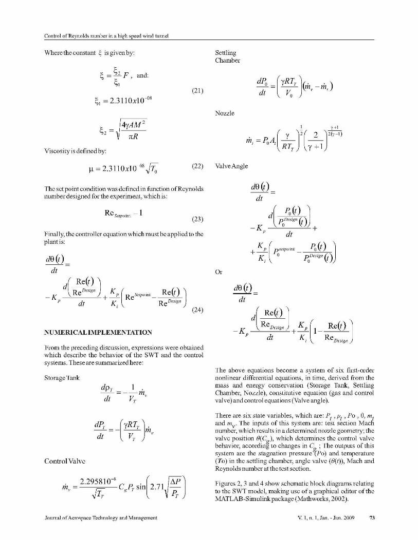
NUMERICALIMPLEMENTATlON
From the preceding discussion, expressions were obtainedwhich describe the behavior of the SWT and the controlsystems. These are summarizedhere:
dPr =_(YRTr \;¡di V
r) ,.
Control Valve
. = 2.295810-se D ' l2 71~M Jm ; ~ g L r SIn .
-v I r PT
There are six state variables, which are: Pt ,Pt ' Po , 8, mtand mv. The inputs of this system are: test section Machnumber, which results in a determined nozzle geometry; thevalve position B(Cg ), which determines the control valvebehavior, according to changes in C ; The outputs of thissystem are the stagnation pressure~Po) and temperature(To) in the settling chamber, angle valve (/J(t)), Mach andReynolds number at thetest section.
Figures 2, 3 and 4 show schematic block diagrams relatingto the SWT model , making use of a graphical editor of theMATLAB-Simulink package (Mathworks, 2002).
Journal ofAerospace Technology and Management V. 1, n. 1, Jan. - Jun. 2009 73

Silva, M.G.; Gamarra, VO.R.; Koldaev, V
Figure2: Blockdiagram:StagnationPressure Controller
¡;
+-'----+---+---
~ r--Re!
C9 C9 PO
PO
L-- '--ConteollerRey WindTunnel
Step
Figure 5: Windtunnelwithoutcontroller
1---+1""S" .-------+1 PO Cg~---+I Cg
1'01----,Wind Tunnel with Stagnation Pressure Control
Figure3: Blockdiagram: Reynolds Controller
TO
ConIeoIlerRey
TO
WlndTunnel
In arder to compare the experimental results with thosefrom the mathematical model simulation, the sameconditions adopted by Fung (1987) were established forthepresent case. The research of Fung (1987) deals with thesolution of the stagnation pressure control problem at thesettling chamber in the SWT. This reference case is a goodtest to evaluate the concordance among differentmathematical models. By adding a controller in a feedbackloop lo the wind tunnel plant, the mathematical model forthe closed-Ioop system is established. Theresults are shownin Tab.2.
Kp +Kp
1 +R' + Saturation
2 K;IntegratorPO Sum 2Sum 1
Figure4: Blockdiagram: Controller Detail
RESULTS
The results are presented following the sequence below:
Table 2: Comparison ofresults fromsimulation and experimentaldata(PT~260psia)
Mach Po [Psi.] Ruu Time [s] Ruu Time [s]Experimental Present Work
2.5 80 55 49
3.0 110 50 45
3.5 160 40 32
-Wind tunnel without controller;
- Wind tunnel with stagnation pressure control;
- Wind tunnel withReynolds number control;
- Temperature variation;
- Shock position at the diffuser.
Wind Tunnel withont Controller
It can be seen that the performance ofthe real wind tunnel iseven better than the simulation. The reason is theassumption of an adiabatic process in the simulation. Inreality, heat transfer takes place particularly through thelarge taak surface during the test. While the taaktemperature decreases during the test, a fmite amount ofheat is transferred from the tank walls to the inner airo Thisleads lo a higher taak temperature as well as a higher taakpressurethan predicted bythe model, Fung (1987).
Figure 5 shows a comparative picture with the plant withoutcontroller. Although the Mach number at the test sectiondoes not change during the test run (70 sec), there is a bigvariation in terms ofReynolds number. In this context, it ispossible to conclude that Fung's wind tunnel configurationneeds a control system.
Figure 6 shows the behavior ofthe system at Mach number3. The results are expressed in terms of stagnation pressureand stagnation temperature at the settling chamber,stagnation pressure at the tank, Mach and Reynolds numberat the test section, and the angle valve (between the tank andsettling chamber). The stagnation pressure control at the
Journal ofAerospace Technology and Management V 1, n. 1, Jan. - Jun . 2009 74

Control ofReynolds number in a high speed wind tunnel
Ji ]]. ..... · JI
Figure 7: Wind tunnel withReynoldsnumber control
settling chamber was used. It can be concluded that thecontrol system based on the stagnation pressure at thesettling chamber was found to be satisfactory, although theReynolds number was not constant at the test section.Curiously, for this particular configuration, significantvariation in angle ofvalve was not found,
Thus, this control would be run manual!y. Final!y, it can beobserved that the constant average controller parametersfound above are effective at al! Mach number (2.5 to 4.0) inobtaining a response with aminimum steady-state error andovershoot with aminimum settling time.
Figure 6: Wind tunnel with StagnationPressure control
Wind Tunnel with Reynolds number Control
ShockPosition
Figure 8 shows the results obtained using the different typesofcontrol system adopted in this report, The shock positionat the diffuser is directly dependent on stagnation pressureat the settling chamber. So, a constant location is expectedduring the test ron if a stagnation pressure controller isadopted for the plant,
The reason for tracking the shock wave at the diffuser is toevaluate the Mach number at the test section. The test ronsimulation is conducted while the shock wave position isgreaterthan the second throat position.
Figure 7 shows the same configuration adopted in the lastsection but, this time, with the Reynolds numbercontroller. The objective is to compare the resultsobtained for Mach and Reynolds number at the test sectionusing both control methodologies. Although the Machnumber required to ron using FWlg'S control system isachieved, there is a considerable difference between themethods (20 per cent approximately) in tenns ofReynoldsnumber.
18
'"
re
.... , .. .. '.'
:{J0,\-,-~,----;;---~---t,------,;,---*--!.
" r::-------~------~-...,
10 f\., .?\" , ' .. . , ',' .
.. , '.' .
(a) Plantwithout controller
(b) Plantwith stagnation pressure controller
The principal reason for this difference is related to thetemperature involved in this process. The Reynolds numbercontroller considers the temperature variation during thetransient analysis, Eq. (20), adjusting the mass ratio in adifferent way from the stagnation pressure control. Thus, adifferent angle valve variation is expected, Figs. 6 and 7.According lo Pope and Goin (1965), there are two ways inwhich blowdown WT are customarily operated: withstagnation pressure constant or with constant mass flow.For constant mass runs the stagnation temperature must beheld constant and either a heater or a thennal mass externalto the tank is required. For constant stagnation pressure(settling chamber), the only control necessary is a pressureregulator that maintains the stagnation pressure constant.This report considers a relationship between stagnationpressure and (p~"/To)swlingJhambu temperature, wbichcharacterizes the Reynolds number at the test section ascontrol parameter at the planto Finally, it is interesting tonote that tbis mathematical model is an attractive tool foranalyzing different test configurations, which requiredifferent control methodologies.
Journal ofAerospace Technology and Management V. 1, n. 1, Jan. - Jun. 2009 75

"r-- - - - - - - - - - - -,
" .
" .
(e) Plant with Reynolds nmnber controller
Figure 8: Shockposition.
Temperature Variation during the Test
Achieving constant stagnation pressure is a critical concernfor supersonic wind tunnel testing. The control algorithm isdesigned such that it is suitable for different Mach numbertesting and, at the same time, obtaining the maximum testtime for differentstagnation pressures.
However, the temperature variation is another requirementfor the experimental analysis. SincetheReynolds number isa function of stagnation pressure and temperature, it isnecessary to consider the temperature variation in thecontrol algorithm as well, Figure 9 shows the differentprofiles when the plant without controller is considered,with stagnation pressure control and withReynolds numbercontrol.
095
ua
085
us
0 75
"'0 65
uso " ~ ao <O so eo '"
(a) Plant without Controller
0 .95
085
0 .75
0 .65
(b) Plantwith StagnationPressure Controller
Silva, M.G.; Gamarra, VO.R.; Koldaev, V
0.95 .
0.S5 .
os .
0.75
0.65 .
(e) Plantwith Reynolds number Controller
Figure 9: Temperature Variation
The curve shape and the minimum value of temperature isthe principal concem. From these results it is possible toconclude that the algorithm developed for the Reynoldsnumber controller is more efficient when flow quality andtest time are considered.
CONCLUSIONS
A conceptual control model, based on the Reynolds numberat the test section, was established for the supersonic windtunnel. Comparison of the system response of the modelsimulation and the actual wind tunnel test (Fung, 1987) datawas madeto determinethe applicability ofthe model.Two controllers were defined: the first one was based on thestagnation pressure at the settling chamber; the second wasbased on the relation (p~,,/To) SWlinLChambu.
Performance of the supersonic wind tunnel under differentMach numbers and stagnation pressure was tested. Thefollowing conclusions were drawn from the results ofsimulations:
(i) The isentropic approach can be used for preliminarydesign ofthe control system based on stagnation pressure atthe settling chamber or Reynolds number at the test section.According to the single-loop adopted in these analyses, thesecond option is to be preferred since it is possible to obtainMach and Reynolds number control simultaneously. 1t isimportant to stress here that, the principal reason inadopting the control system based on the Reynolds numberat the test section is not directly related to the run time. Theconcern is about quality offlow.
(ii) The mathematical formula applied to the normal shockwave at the diffuser can be an interesting tool to be used inanalysis ofrun time, when the Mach number is consideredas a control parameter. The cases presented in this reportconsider the Mach number at the diffuser greater than theMach number at the test section. It is not a commonpractice. Thus, it is extremely important to analyze thestability of shock wave at the divergent portion of diffuserbefore defining the variable posetpoint;
Journal ofAerospace Technology and Management V 1, n. 1, Jan. - Jun . 2009 76

Control ofReynolds number in a high speed wind tunnel
(iii) After investigating different control algorithms, asingle-input single-output PI controllerhas been chosen forthis task because of its siinplicity and availability. Themajor problem in implementing this control system is thehighly nonlinear relationship ofboth the gas dynamics andthe valve-nozzle characteristics. The linearizedmathematical model was used to analyze the open-loopsystem characteristics as well as for the controller designoHowever, it is interesting to improve tbis mathematicalmodel implementing the gain calculator in orderto providean automated design tool for blow-down wind tunneltesting.
REFERENCES
Buggele,A. E. and Decker, A. J., 1994, "Control ofWindTunnel Operations Using Neural Net InterpolationofFlowVisualization Records", NASA TeclmicalMemorandum106683.
Ficher Control Company, 1984, "Rotary Shaft ControlValve Specifications.", Marshalltown, Iowa, FicherControl Company Report.
Fung, Y T, 1987, "Microprocessor Control ofHigh SpeedWind Tunnel Stagnation Pressure", The Pensylvania StateUniversity, MasterofScience, 59 p.
Fung, Y T., Settles, G. S. and Ray, A., 1988,"Microprocessor Control of High-Speed Wind TunnelStagnation Pressure", AIAA Joumal, Vo1.2, N0.14 pp429.
Kuethe, A. M., Chow, C. Y, 1998, "Foundations ofAerodynamics", Fifth Edition, John Wiley & Sons, NewYork.
Marvin, J. G., 1987, "Wind Tunnel Requirements forComputational Fluid Dynamics Code Verification", USA,NASATechnicalMemorandum 100001.
Matsumoto J., Lu, F. K. and Wilson, D. R., 2001, "PrePrograrnmed Controller For A Supersonic BlowdownTunnel", 95th Meeting of the Supersonic TunnelAssociation International,Hampton,VA
Pope,A., and Goin, K. 1..,1965, "High Speed Wind TunnelTesting," John Wiley & Sons, New York.
Silva, M. G., Falcao, J.B.P.F and Mello, O. A. F., "Controlof High Speed Wind Tunnel Stagnation Pressure",Proceedings of the 11th Brazilian Congress of ThermalSciences and Engineering (ENClT), Dec 5-8, 2006, ClT060921, Curitiba, Brasil.
TheMathWorks, Inc., 2002, Using Simuliiik (Version 5).
Journal ofAerospace Technology and Management V. 1, n. 1, Jan. - Jun. 2009 77
Copyright © 2022 FDOKUMEN