
Reconfigurable Radio Systems: Network Architectures and Standards
68
JWST317-c01 JWST317-Iacobucci Printer: Yet to Come March 28, 2013 7:25 Trim: 244mm × 170mm 1 The Multiradio Access Network 1.1 Introduction Network evolution in the past decade regarded the introduction of new access technologies, both fixed and wireless, using an Internet protocol (IP) backbone for all originating and termi- nating services. The evolution of the fixed access network mainly concerns the introduction of the optical fibre, with point-to-point or passive optical network (PON) architectures. Gigabit passive optical network (GPON) architectures deal with fibre optic deployment up to different points in the access network: • Fibre to the cabinet (FTTCab), if the fibre stops at the cabinet, • Fibre to the building (FTTB), if the fibre stops at the building, and • Fibre to the home (FTTH), if the fibre stops at the customer’s home. Figure 1.1 shows FTTCab, FTTB and FTTH network architectures. Such architectures reach a downstream bit rate per user in the order of magnitude respectively up to 50 Mbps, up to 100 Mbps and up to 1 Gbps. The optical network is called passive because of the splitters, which repeat the input signal. The outgoing bandwidth of an optical line termination (OLT) is shared among many optical network units (ONUs), and in FTTCab and FTTB architectures the existing copper cable pair is used in the connection from the ONU up to the end users, with very high digital subscriber line (VDSL) transmissions. If the optical fibre reaches the home, the architecture is FTTH and the user will be provided with an optical modem called network termination (NT). In the point-to-point architecture, there is one optical fibre connecting the end user to the central office, completely replacing the copper cable pair. In this case one fibre is dedicated to one user and therefore the provided bandwidth can be very high, even tens of Gbps. Figure 1.2 shows an example of the point-to-point fibre architecture in the access network. The point-to-point architecture, handling much more fibre optics than GPON, requires more spaces in the central office and absorbs much more power. Because of that, most operators have chosen the GPON architecture for fixed access network evolution. The next generation access network (NGAN) also includes radiomobile and wireless access technologies that, thanks to the adoption of advanced radio features, reach a maximum bit Reconfigurable Radio Systems: Network Architectures and Standards, First Edition. Maria Stella Iacobucci. © 2013 John Wiley & Sons, Ltd. Published 2013 by John Wiley & Sons, Ltd. 1 COPYRIGHTED MATERIAL
-
Upload
independent -
Category
Documents
-
view
4 -
download
0
Transcript of Reconfigurable Radio Systems: Network Architectures and Standards

JWST317-c01 JWST317-Iacobucci Printer: Yet to Come March 28, 2013 7:25 Trim: 244mm × 170mm
1The Multiradio Access Network
1.1 Introduction
Network evolution in the past decade regarded the introduction of new access technologies,both fixed and wireless, using an Internet protocol (IP) backbone for all originating and termi-nating services. The evolution of the fixed access network mainly concerns the introductionof the optical fibre, with point-to-point or passive optical network (PON) architectures.
Gigabit passive optical network (GPON) architectures deal with fibre optic deployment upto different points in the access network:
• Fibre to the cabinet (FTTCab), if the fibre stops at the cabinet,• Fibre to the building (FTTB), if the fibre stops at the building, and• Fibre to the home (FTTH), if the fibre stops at the customer’s home.
Figure 1.1 shows FTTCab, FTTB and FTTH network architectures. Such architectures reacha downstream bit rate per user in the order of magnitude respectively up to 50 Mbps, up to100 Mbps and up to 1 Gbps. The optical network is called passive because of the splitters,which repeat the input signal. The outgoing bandwidth of an optical line termination (OLT) isshared among many optical network units (ONUs), and in FTTCab and FTTB architecturesthe existing copper cable pair is used in the connection from the ONU up to the end users,with very high digital subscriber line (VDSL) transmissions. If the optical fibre reaches thehome, the architecture is FTTH and the user will be provided with an optical modem callednetwork termination (NT).
In the point-to-point architecture, there is one optical fibre connecting the end user to thecentral office, completely replacing the copper cable pair. In this case one fibre is dedicatedto one user and therefore the provided bandwidth can be very high, even tens of Gbps.Figure 1.2 shows an example of the point-to-point fibre architecture in the access network.
The point-to-point architecture, handling much more fibre optics than GPON, requires morespaces in the central office and absorbs much more power. Because of that, most operatorshave chosen the GPON architecture for fixed access network evolution.
The next generation access network (NGAN) also includes radiomobile and wireless accesstechnologies that, thanks to the adoption of advanced radio features, reach a maximum bit
Reconfigurable Radio Systems: Network Architectures and Standards, First Edition. Maria Stella Iacobucci.© 2013 John Wiley & Sons, Ltd. Published 2013 by John Wiley & Sons, Ltd.
1
COPYRIG
HTED M
ATERIAL

JWST317-c01 JWST317-Iacobucci Printer: Yet to Come March 28, 2013 7:25 Trim: 244mm × 170mm
OLT
ONU-B
splitter
splitter
splitter
GPON
ONU-B
ONU-B
ONU-B
Building
Copper cable pair
Optical fibre
Central
office
ONU
Cabinet
ONU
Cabinet
NT
NT
VDSL
V
D
S
L
V
D
S
L
VDSL
VDSL
VDSL
VDSL
VDSL
home
Figure 1.1 FTTCab, FTTB and FTTH fixed access network architectures.
Optical fibre
Central
office
home
Figure 1.2 Point-to-point fibre architecture in the access network.
2

JWST317-c01 JWST317-Iacobucci Printer: Yet to Come March 28, 2013 7:25 Trim: 244mm × 170mm
The Multiradio Access Network 3
IP based Transport Network, with QoS
FTTx WiMax
GSM/GPRS/EDGE
UMTS/HSPA/HSPA+
ADSL
LTE
WLAN
……
Figure 1.3 Many accesses and one core.
rate of hundreds of Mbps. Among radiomobile technologies, the global system for mobilecommunications (GSM) and its evolutions for data transmission, the general packet radioservice (GPRS) and enhanced data rates for GSM evolution (EGDE), have been largelydeployed all around the world. The third generation radiomobile system, the universal mobiletelecommunication system (UMTS), with its evolutions, HSPA (high speed packet access)and HSPA+ for high bit rates data transmission, has been deployed with targeted coveragein high traffic areas, like major and minor cities. Long term evolution (LTE) is operating inmany countries and is going to be deployed in others. Wireless local area networks (LANs)and WiMAX (see Section 1.3.2) are other existing technologies used mostly for data but alsofor voice transmission.
The different access networks, which collect all originating and terminating services, areconnected to an IP-based backbone, offering a transport service with quality of service (QoS).Figure 1.3 shows the network with one core and many accesses.
1.2 Radiomobile Networks
Radiomobile networks were standardized with the aim of extending the services provided bythe fixed network to mobile users, by means of a wireless terminal with the ability to movewhile the connection is in progress.
First generation systems, like the total access communication system (TACS), providedonly the voice service, which was transmitted over the radio interface using frequency divisionmultiple access (FDMA). The digital GSM system [1], initially standardized mainly for voiceservice, with its GPRS and EDGE evolutions, added new features in the access network andnew nodes in the core in order to optimize data transmission.
The third generation system UMTS, standardized for multimedia, includes in its evolutionsHSPA and HSPA+, which are able to reach higher bit rates and decrease latency. Finally, LTEreaches bit rates of hundreds of Mbps in downlink and lower latency times. The advancedversion of LTE (LTE advanced) promises rates of Gbps.
In this section second, third and fourth generation radiomobile networks are described interms of network architecture, access network and radio interfaces.

JWST317-c01 JWST317-Iacobucci Printer: Yet to Come March 28, 2013 7:25 Trim: 244mm × 170mm
4 Reconfigurable Radio Systems
Other Networks
GMSC
HLR
BSC
MSC
VLR
MSC
VLR
BSC
VLR
BSC
BSC
A
BSCBTS
Abis
signalling (C-plane)
data (U-plane)
MS
cell
Figure 1.4 GSM network architecture.
1.2.1 GSM/GPRS/EDGE Network Architecture
Figure 1.4 shows the GSM network architecture. The first network element is the mobilestation (MS), which includes the mobile terminal (MT) and the subscriber identity module(SIM). Its principal functions are transmission and reception over the radio interface, radiochannels supervision, cell selection, measurements of downlink radio parameters and exe-cution of access, authentication and handover procedures. The MS communicates through astandardized radio interface with the base transceiver station (BTS), which is the network nodethat realizes one or more radio coverage cells, measures uplink radio parameters, broadcastssystem information and executes procedures like paging. Each BTS is connected, through theAbis interface, to the base station controller (BSC), which controls the BTS radio resources. Itassigns and releases the radio channels to the mobile users, receives uplink and downlink mea-surements, performs intra-BSC handover, handles power control, resolves cells congestions,etc.
Because the Abis interface is not standardized, the BTSs and the connected BSCs must befrom the same vendor. The BSC with its connected BTSs form a base station subsystem (BSS)and represent the GSM access network nodes. The BSSs are connected to the core network,which includes switching nodes like mobile switching centres (MSCs) and databases like thevisitor location register (VLR) and home location register (HLR). BSCs are connected to theMSC through the standard A interface.
The principal functions of an MSC are: call handling, mobility handling (through inter-working with VLR and HLR), paging, intra-MSC handover, inter-MSC handover, toll-ticketgeneration. Associated to the MSC is the VLR, which is a database containing a record foreach user registered in the MSC/VLR area. Some of the MSCs are gateways (GMSC), because

JWST317-c01 JWST317-Iacobucci Printer: Yet to Come March 28, 2013 7:25 Trim: 244mm × 170mm
The Multiradio Access Network 5
they are connected to the other mobile operator’s networks and to the fixed network, in orderto handle all the mobile–mobile, mobile–fixed and fixed–mobile calls.
The HLR is a register that stores, for each user of the mobile network, the service profile,the key for authentication and encryption, the international mobile subscriber identity (IMSI)and mobile station ISDN (MSISDN), as well as an identifier of the VLR where the user isregistered. When an MS registers to the network, the VLR creates a new record with the userprofile downloaded from the HLR and the MS position in terms of the location area (LA).In the HLR the identifier of the actual VLR is updated. The VLR also assigns the temporaryIMSI (TMSI), which temporarily substitutes the IMSI.
The LA is a logical concept including a certain number of cells. The location area identifier(LAI) is broadcasted from the BTSs in all the cells belonging to the LA. When an MS movesfrom one LA to another, it performs the LA updating procedure. If the new LA belongs to anew MSC, then the new VLR downloads the user profile from the HLR and registers the newuser with its LA. The HLR updates the VLR identifier and instructs the old VLR to delete therecord of the user.
A GSM network with its core based on circuit-switching nodes, the MSCs, is well suitedfor voice but it is not for data. GSM data transmission is possible, but at a fixed bit rate of9.6 kbps and using a voice-equivalent channel for all the duration of the call. Billing is basedon the call duration and not on the amount of the exchanged data.
GPRS is the GSM evolution for data transmission. It introduces new features in the accessnetwork nodes in order to enhance data transmission speed and optimize resource allocation.In particular, GPRS needs new encoders in the BTSs and a new module, the packet control unit(PCU), in the BSC. The PCU implements radio resource management (RRM) algorithms fordata transmission. GPRS also introduces new core network nodes: the serving GPRS supportnode (SGSN) and the gateway GPRS support node (GGSN).
The SGSN is responsible for the delivery of data packets from and to the mobile stationswithin its service area. Its tasks include packet routing and transfer, mobility management(attach/detach and location management), logical link management, authentication and charg-ing functions. The location register of the SGSN stores location information and user profilesused in the packet data network of all GPRS users registered with this SGSN.
The GGSN is the node having connections with the other packet data networks. It containsrouting information for the connected GPRS users. The routing information is used to tunnelpacket data units (PDUs) to the MS’s current point of attachment, that is the SGSN.
The BSC is connected to the SGSN through the standard Gb interface; the connectionbetween SGSN and GGSN is the Gn interface; SGSN and GGSN are connected to theHLR through respectively the Gr and Gc interfaces; SGSN and MSC/VLR can see eachother through the Gs interface. Gs and Gc interfaces are not mandatory. If Gs is present, anassociation between MSC/VLR and GGSN is created and it is possible to jointly handle amobile station with packet switched and circuit switched services. Gs was introduced in orderto reduce signalling over the radio interface. In fact, it is possible to carry out procedures likeregistration (IMSI attach) through the SGSN, combined LA and routing area (RA) updates,IMSI detach, etc. The RA is the equivalent of the LA in the GPRS domain; in general an LAcontains an integer number of RAs.
A GPRS data transmission reaches a maximum download bit rate of about 50 kbps. EDGE,also called enhanced GPRS (EGPRS), is an evolution of GPRS allowing downlink bit rates upto about 240 kbps. EDGE adds new radio features to the GSM/GPRS access network nodes,

JWST317-c01 JWST317-Iacobucci Printer: Yet to Come March 28, 2013 7:25 Trim: 244mm × 170mm
6 Reconfigurable Radio Systems
Other Networks
HLR
VLR
GMSCMSC
GrG signalling (C-plane)
data (U-plane)
Gb
A
BSC
SGSNGGSNGn
GcGs
GGSN
BTS
cell
Abis
Other Packet Networks MS
Figure 1.5 GSM/GPRS/EDGE network architecture.
and reuses the GPRS core network nodes: SGSN and GGSN. In particular, new modulatorsand encoders are added in the BTSs and new software in the PCU, in order to manage higherbit rate data connections.
Figure 1.5 shows the GSM/GPRS/EDGE network architecture. The access network, withits BSCs and BTSs, is shared among GSM and GPRS. The MSC-based core transports voiceservices and the SGSN/GGSN-based core transports data services.
1.2.2 GSM/GPRS/EDGE Access Network
The GSM/GPRS/EDGE access network, also called the GERAN (GSM EDGE radio accessnetwork), includes MSs, BTSs, BSCs, and related interfaces. The radio interface is based onfrequency division duplex (FDD) and FDMA/TDMA (time division multiple access). Table 1.1shows GSM/GPRS/EDGE working frequencies in different countries of the world.
Table 1.1 GSM working frequencies in different countries of the world
Band Uplink (MHz) Downlink (MHz)
GSM 900 880–915 925–960GSM 1800 1710–1785 1805–1880PCS (personal communication
service) 19001850–1910 1930–1990
Cellular 850 824–849 869–894
JWST317-c01 JWST317-Iacobucci Printer: Yet to Come March 28, 2013 7:25 Trim: 244mm × 170mm
The Multiradio Access Network 7
880
925
915
960Frequency (MHz)
200 kHzMS →BTS
Uplink
BTS → MSDownlink
200 kHz
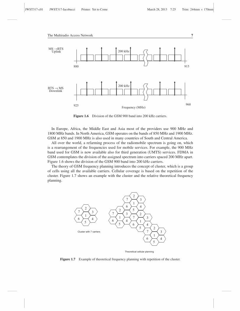
Figure 1.6 Division of the GSM 900 band into 200 kHz carriers.
In Europe, Africa, the Middle East and Asia most of the providers use 900 MHz and1800 MHz bands. In North America, GSM operates on the bands of 850 MHz and 1900 MHz.GSM at 850 and 1900 MHz is also used in many countries of South and Central America.
All over the world, a refarming process of the radiomobile spectrum is going on, whichis a rearrangement of the frequencies used for mobile services. For example, the 900 MHzband used for GSM is now available also for third generation (UMTS) services. FDMA inGSM contemplates the division of the assigned spectrum into carriers spaced 200 MHz apart.Figure 1.6 shows the division of the GSM 900 band into 200 kHz carriers.
The theory of GSM frequency planning introduces the concept of cluster, which is a groupof cells using all the available carriers. Cellular coverage is based on the repetition of thecluster. Figure 1.7 shows an example with the cluster and the relative theoretical frequencyplanning.
1
2 3
4 5
7
6
Cluster with 7 carriers
1
2 3
4 5
7
6 1
2 3
4 5
7
6
1
2 3
4 5
7
6
1
2 3
4 5
7
6
Theoretical cellular planning
Figure 1.7 Example of theoretical frequency planning with repetition of the cluster.

JWST317-c01 JWST317-Iacobucci Printer: Yet to Come March 28, 2013 7:25 Trim: 244mm × 170mm
8 Reconfigurable Radio Systems
As very often happens, the reality is far from the theory. The goal of cell planning is toguarantee the availability of radio resources that satisfy QoS for the provision of a set ofservices in an area target. In general, forms and dimensions of each cell are different and ineach cell one or more carriers are switched on, depending on the requirements of coverage,capacity and performances. When GSM 900 and GSM 1800 coexist, an overlay/underlaytechnique is used for coverage. The underlay coverage is in general at 900 MHz and covers ahigher area than overlay cells working at 1800 MHz. Overlay and underlay cells share sites,antenna systems and control channels.
Among cells of different dimensions, there are the macro, micro and pico cells dependingon the size. Micro and pico cells are used to solve traffic peaks in small areas. Figure 1.8 showsan example of macro and micro coverage.
GSM multiple access is FDMA/TDMA and is based on a frame structure of eight time slotsper carrier, as shown in Figure 1.9. The frame duration is 4.6 ms; the slot duration is 577 μs;the signal burst is contained in one time slot and lasts 546 μs.
The transmission and reception frames are shifted by three time slots. This allows the mobilestation transceiver to transmit over the uplink, move to the downlink frequency, receive thedownlink signal and make measurements over the other radio channels. This process is shownin Figure 1.10.
The GSM frames are grouped together to form multiframes, superframes and iperframes.This temporal structure allows the establishment of a time schedule for operation and net-work synchronization. In particular, one multiframe can be formed of 26 or 51 frames; onesuperframe lasts 6.12 s and is formed of 51 multiframes of 26 frames or 26 multiframes
macro coverage
micro coverage
Figure 1.8 Example of macro and micro coverage.

JWST317-c01 JWST317-Iacobucci Printer: Yet to Come March 28, 2013 7:25 Trim: 244mm × 170mm
The Multiradio Access Network 9
FDMA FDMA
time
07
56
TDMA
23
4
5
0
frequency200 kHz 200 kHz
1 1
Figure 1.9 FDMA/TDMA multiple access in GSM.
of 51 frames; one iperframe is formed of 2048 superframes and lasts 3 h, 28 min, 53 s and760 ms.
GSM access includes, as an optional feature, frequency hopping (FH). The goal of frequencyhopping in GSM is to obtain an intrinsic diversity in frequency that protects the transmissionfrom effects like rapid fluctuations of the radio channel or cochannel interferences. There area total of 63 different hopping algorithms available in GSM.
When the BTS orders the MS to switch to the frequency hopping mode, it also assigns alist of channels and the hopping sequence number (HSN), which corresponds to the particularhopping algorithm that will be used. Figure 1.11 shows the principle of frequency hopping.
1.2.2.1 GSM Physical and Logical Channels
A physical channel in the GSM access network is identified from the time slot in the frame,the frame number, an FH sequence (if FH is active). A logical channel is dedicated to the
Transmission frame
0 1 5 2 3 4 7 6 0 1 5 2 3 4 7 6 0 1 5 2 3 4 7 6
Reception frame
5 6 2 7 0 1 4 3 5 6 0 1 3 2 3
Measurements over other cells
Figure 1.10 GSM transmission and reception.

JWST317-c01 JWST317-Iacobucci Printer: Yet to Come March 28, 2013 7:25 Trim: 244mm × 170mm
fram
e 1
fr
ame
2
fram
e3
freq
uen
cy
tim
e
200 KHz
fram
e4
Fig
ure
1.11
Prin
cipl
eof
freq
uenc
yho
ppin
g.
10

JWST317-c01 JWST317-Iacobucci Printer: Yet to Come March 28, 2013 7:25 Trim: 244mm × 170mm
The Multiradio Access Network 11
transmission of specific information, using a mapping over appropriate physical resources.Logical channels are divided into traffic channels (TCHs), carrying voice and data, and controlchannels (CCHs), carrying control information.
GSM TCHs are:
• TCH/FS: full rate (FR) speech• TCH/HS: half rate (HR) speech• TCH/F9.6: data at 9.6 kbps (FR)• TCH/F4.8: data at 4.8 kbps (FR)• TCH/F2.4: data at 2.4 kbps (FR)• TCH/F1.2: data at 1.2 kbps (FR)
Also half rate data channels at 4.8 and 2.4 kbps are defined.Full rate traffic channels use one time slot per frame; half rate channels use one time slot
each two frames, occupying half capacity. The gross bit rate of a full rate channel is 22.8 kbps;the gross bit rate of an half rate channel is 11.4 kbps.
CCHs are divided into broadcast channels (BCHs), carrying broadcast information, commoncontrol channels (CCCHs), carrying common signalling information, and dedicated controlchannels (DCCHs) carrying signalling information dedicated to a user.
Figure 1.12 shows control and traffic channel mapping.In downlink, BCHs are:
• FCCH: frequency correction channel, carrying a frequency reference signal• SCH: synchronization channel, carrying a frame synchronization reference signal and a base
station identity code (BSIC)
CCH
BCH CCCH DCCH
FCCH SCH BCCH
PCH AGCH RACH
SDCCH SACCH FACCH
TCH
TCH/F TCH/H
Figure 1.12 GSM logical channels mapping.

JWST317-c01 JWST317-Iacobucci Printer: Yet to Come March 28, 2013 7:25 Trim: 244mm × 170mm
12 Reconfigurable Radio Systems
• BCCH: broadcast control channel, carrying a cell global identity (CGI), location area identity(LAI), frequency hopping algorithm, references for control channels of adjacent cells andother cell parameters
CCCHs are:
• PCH: paging channel, where the downlink is sent to search for an MS having an incomingcall and paging is broadcast over all the cells belonging to the MS location area
• AGCH: access grant channel, where the downlink is used to allocate a standalone dedicatedcontrol channel (SDCCH) to the MS
• RACH: random access channel, where the uplink carries user access information and is usedfrom the MS to request an SDCCH allocation
DCCHs are:
• SDCCH: standalone dedicated control channel, which is bidirectional and uses to executesignalling procedure like location area updating, TMSI allocation, attach and detach andoccupies an eighth of one slot
• SACCH: standalone associated control channel, which is bidirectional and carries controlinformation related to an active connection like measurement reports in uplink and powercontrol and timing advance in downlink
• FACCH: fast associated control channel, which is bidirectional and uses one TCH by sub-stituting signalling to the traffic (frame stealing), in general carrying handover information
Figures 1.13, 1.14 and 1.15 show examples of logical channels usage over the radio interfacein location area updating, mobile-terminated and mobile-originating call procedures.
Channel Request (RACH)
Channel Assignment (AGCH)
Request for Location Updating (SDCCH)
Authentication Request (SDCCH)
Authentication Response (SDCCH)
Ciphering Command (SDCCH)
Ciphering Complete (SDCCH)
Location updating confirmation (SDCCH)
Ack (SDCCH)
Channel release (SDCCH)
MS Base
Station
Figure 1.13 Location area updating procedure over the radio interface.

JWST317-c01 JWST317-Iacobucci Printer: Yet to Come March 28, 2013 7:25 Trim: 244mm × 170mm
Channel Request (RACH)
Channel Assignment (AGCH)
Call establishment Request (SDCCH)
Authentication Request (SDCCH)
Authentication Response (SDCCH)
Ciphering Command (SDCCH)
Ciphering Complete (SDCCH)
Setup message (carries the MS-ISDN number) (SDCCH)
Call Proceeding (SDCCH)
Assignment of a traffic channel (SDCCH)
Assignment complete (FACCH)
Alerting (ringing) (FACCH)
Connect (FACCH)
Connect Ack (FACCH)
conversation (TCH)
MS
Base
Station
Figure 1.14 Mobile-originating call procedure over the radio interface.
Paging from the network to the BS
Channel Request (RACH)
Channel Assignment (AGCH)
Answer to the paging (SDCCH)
Authentication Request (SDCCH)
Authentication Response (SDCCH)
Ciphering Command (SDCCH)
Ciphering Complete (SDCCH)
Setup message (carries the MS-ISDN number) (SDCCH)
Call Proceeding (SDCCH)
Assignment of a traffic channel (SDCCH)
Assignment complete (FACCH)
Alerting (ringing) (FACCH)
Connect (FACCH)
Connect Ack (FACCH)
conversation (TCH)
MS
Base
Station
Figure 1.15 Mobile-terminated call procedure over the radio interface.
13
JWST317-c01 JWST317-Iacobucci Printer: Yet to Come March 28, 2013 7:25 Trim: 244mm × 170mm
14 Reconfigurable Radio Systems
1.2.2.2 GSM/GPRS Modulation
The GSM and GPRS modulation technique is a Gaussian minimum shift keying (GMSK); itis a minimum shift keying (MSK) with a premodulation Gaussian filter.
The GMSK was chosen as a compromise between spectral efficiency, realization complexityand low emission of spurious radiations (with low adjacent channel interference). The GMSKimproves the spectral efficiency respect to the MSK because the power spectral density (PSD)presents a reduced main lobe compared to the MSK. The modulation rate is 270 × (5/6)kbauds.
1.2.2.3 GPRS Radio Interface
GPRS is the GSM evolution for data transmission [2]. It implies the introduction of newnetwork nodes in the core network and new features in the access network to increase themaximum bit rate and optimize the usage of radio resources for data transmission. Physicalchannels are not allocated permanently to a GPRS connection, but only when data have to betransmitted over the radio interface.
GPRS shares with GSM the radio resources and introduces the following possibilities:
• More than one time slot of a TDMA frame can be assigned to an MS.• More than one MS can be multiplexed on the same time slot.• Radio resources are separately assigned to uplink and downlink (asymmetric transmission
and reception).• GSM and GPRS can use the same time slot at different times.• GSM has higher priority than GPRS.• GPRS assigned resources can be dropped.
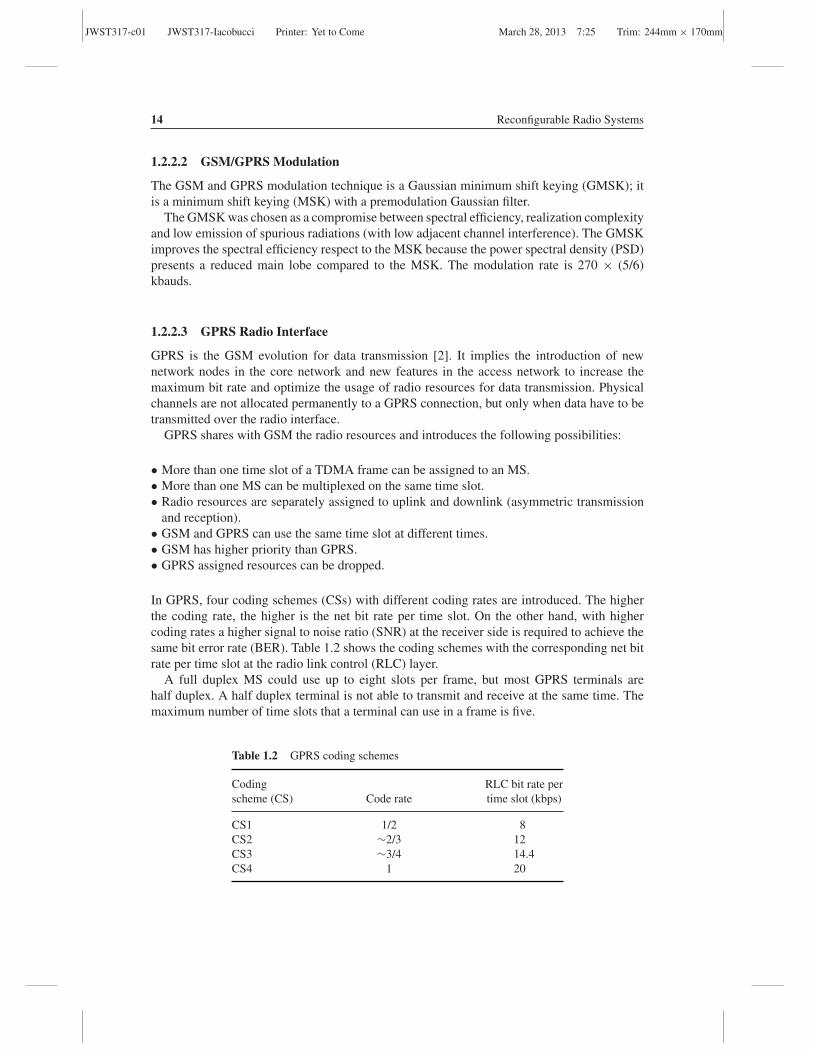
In GPRS, four coding schemes (CSs) with different coding rates are introduced. The higherthe coding rate, the higher is the net bit rate per time slot. On the other hand, with highercoding rates a higher signal to noise ratio (SNR) at the receiver side is required to achieve thesame bit error rate (BER). Table 1.2 shows the coding schemes with the corresponding net bitrate per time slot at the radio link control (RLC) layer.
A full duplex MS could use up to eight slots per frame, but most GPRS terminals arehalf duplex. A half duplex terminal is not able to transmit and receive at the same time. Themaximum number of time slots that a terminal can use in a frame is five.
Table 1.2 GPRS coding schemes
Coding RLC bit rate perscheme (CS) Code rate time slot (kbps)
CS1 1/2 8CS2 ∼2/3 12CS3 ∼3/4 14.4CS4 1 20

JWST317-c01 JWST317-Iacobucci Printer: Yet to Come March 28, 2013 7:25 Trim: 244mm × 170mm
The Multiradio Access Network 15
0 7 0 1
Tt
Rx
Rx frame
0 7 0 1
Tra
1
Tx frame
Rx: reception time
Tx: transmission time
Tt: Rx/Tx switching time
Tra: neighbouring cells measuring time
Tx
Figure 1.16 Example of a GPRS asymmetric transmission (4 + 1).
Figure 1.16 shows the usage of four slots in downlink and one slot in uplink (4 + 1) froma simplex terminal. The figure shows the reception time in four slots in downlink (Rx), thetime needed to switch to the transmission frame (Tt), the transmission time in one slot (Tx) inuplink, the neighbouring cells measuring time (Tra) and the lasting two slots.
The standard defines GPRS logical channels, also called packed data logical channels(PDCH).
They are:
• Packet common control channels (PCCCHs):– Packet random access channel (PRACH): for random access (uplink)– Packet paging channel (PPCH): for paging (downlink)– Packet access grant channel (PAGCH): for access grant (downlink)– Packet notification channel (PNCH): for point-to-multipoint-multicast (PTM-M) notifi-
cation (downlink)• Packet broadcast control channel (PBCCH): used to broadcast system information to GPRS
mobile stations (downlink)• Packet traffic channels (PTCHs):
– Packet dedicated traffic channel (PDTCH): bidirectional, carries packet data traffic• Packet dedicated control channels (PDCCHs):
– Packet associated control channel (PACCH): bidirectional, carries associated control to adata connection
– Packet timing advance control channel (PTCCH): bidirectional, carries in uplink accessbursts that allow the network to calculate the timing advance, which is then transmittedover the same channel in a downlink timing advance value corresponding to the time asignal takes from the mobile station to the BTS
An operator can choose not to reserve dedicated resources to GPRS control channels. In thiscase, packet control channels are not configured over the radio interface and GPRS serviceshares control channels with GSM: a GPRS mobile station receives specific GPRS systeminformation on the broadcast control channel (BCCH).

JWST317-c01 JWST317-Iacobucci Printer: Yet to Come March 28, 2013 7:25 Trim: 244mm × 170mm
16 Reconfigurable Radio Systems
In the case where packet control channels are configured, a GPRS mobile station monitorsthe PBCCH, where specific GPRS system information is sent other than some informationrelated to circuit switched services. If that happens, a GPRS mobile is not requested to monitorthe BCCH.
1.2.2.4 EDGE Radio Interface
EDGE is an evolution of GPRS, especially in relation to the radio interface. It is also calledenhanced GPRS (EGPRS). The principal goal is to increase the data rate through improvedspectral efficiency.
The main features introduced in EDGE are:
• Eight phase shift keying (8PSK) modulators other than GMSK modulators,• New modulation and coding schemes (MCSs),• Link adaptation: varies the modulation and coding scheme (MCS) in relation to the quality
of the radio channel, and• Hybrid automatic repeat request (HARQ): combines two techniques, FEC (forward correct-
ing coding) with ARQ (automatic repeat request).
Table 1.3 shows the nine EDGE modulation and coding schemes (MCSs) with the relatedRLC data rates per time slot. The higher the data rate per time slot, the higher is the requiredSNR at the receiver side.
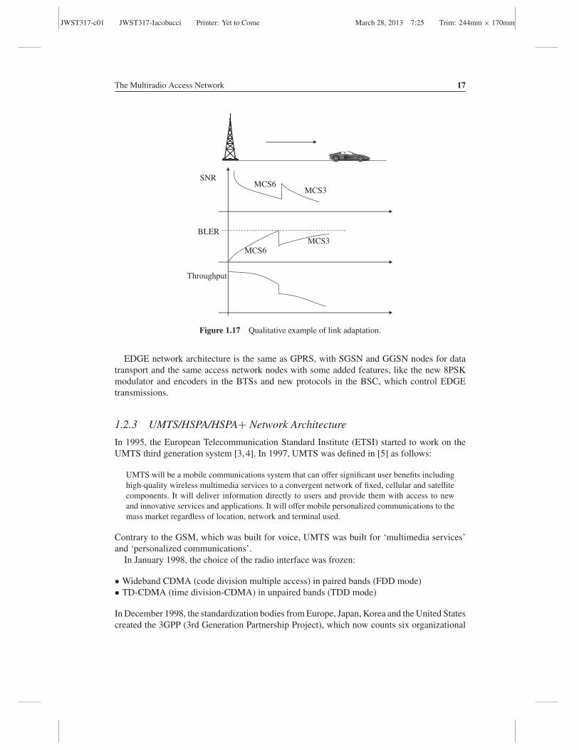
The maximum downlink bit rate per user is about 240 kbps, obtained considering fourassigned time slots encoded with MCS9. Each MCS belongs to a class (A, B, C). The linkadaptation varies if the channel conditions degrade and the modulation and coding scheme iswithin the same class for the retransmission of the same packet. Figure 1.17 shows a qualitativeexample of link adaptation. In the example, the data transmission starts with MCS6. If thereceived SNR decreases, the block error rate (BLER) increases, and the modulation and codingscheme is switched to MCS3, at the expense of the throughput.
Table 1.3 EDGE modulation and coding schemes
RLC data rate perMCS Family Modulation Code rate time slot (kbps)
MCS9 A 8PSK (3 bits/ 1/2 59.2MCS8 A modulation ∼2/3 54.4MCS7 B symbol) ∼3/4 44.8MCS6 A 1 29.6MCS5 B 1/2 22.4
MCS4 C GMSK (1 bit/ ∼2/3 17.6MCS3 A modulation ∼3/4 14.8MCS2 B symbol) 1 11.2MCS1 C 1 8.8
JWST317-c01 JWST317-Iacobucci Printer: Yet to Come March 28, 2013 7:25 Trim: 244mm × 170mm
The Multiradio Access Network 17
MCS6
MCS6MCS3
SNR
BLER
Throughput
MCS3
Figure 1.17 Qualitative example of link adaptation.
EDGE network architecture is the same as GPRS, with SGSN and GGSN nodes for datatransport and the same access network nodes with some added features, like the new 8PSKmodulator and encoders in the BTSs and new protocols in the BSC, which control EDGEtransmissions.
1.2.3 UMTS/HSPA/HSPA+ Network Architecture
In 1995, the European Telecommunication Standard Institute (ETSI) started to work on theUMTS third generation system [3, 4]. In 1997, UMTS was defined in [5] as follows:
UMTS will be a mobile communications system that can offer significant user benefits includinghigh-quality wireless multimedia services to a convergent network of fixed, cellular and satellitecomponents. It will deliver information directly to users and provide them with access to newand innovative services and applications. It will offer mobile personalized communications to themass market regardless of location, network and terminal used.
Contrary to the GSM, which was built for voice, UMTS was built for ‘multimedia services’and ‘personalized communications’.
In January 1998, the choice of the radio interface was frozen:
• Wideband CDMA (code division multiple access) in paired bands (FDD mode)• TD-CDMA (time division-CDMA) in unpaired bands (TDD mode)
In December 1998, the standardization bodies from Europe, Japan, Korea and the United Statescreated the 3GPP (3rd Generation Partnership Project), which now counts six organizational
JWST317-c01 JWST317-Iacobucci Printer: Yet to Come March 28, 2013 7:25 Trim: 244mm × 170mm
18 Reconfigurable Radio Systems
1900 1980 2010 2025 2110 2170 1920
T D
D
F D
D
F D
D
T D
D
FDD frequency Division Duplex TDD Time Division Duplex
MHz
Figure 1.18 European bands designed for UMTS.
partners (the Japanese ARIB, the American ATIS, the Chinese CCSA, the European ETSI,the Korean TTA and the Japanese TCC) and many market representation partners. The 3GPPoriginal mandate was to develop specifications for the UMTS third generation mobile systembased on a new access network and a core network evolved from the GSM/GPRS/EDGE corenetwork.
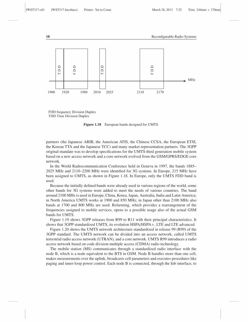
In the World Radiocommunication Conference held in Geneva in 1997, the bands 1885–2025 MHz and 2110–2200 MHz were identified for 3G systems. In Europe, 215 MHz havebeen assigned to UMTS, as shown in Figure 1.18. In Europe, only the UMTS FDD band isused.
Because the initially defined bands were already used in various regions of the world, someother bands for 3G systems were added to meet the needs of various countries. The bandaround 2100 MHz is used in Europe, China, Korea, Japan, Australia, India and Latin America;in North America UMTS works at 1900 and 850 MHz; in Japan other than 2100 MHz alsobands at 1700 and 800 MHz are used. Refarming, which provides a rearrangement of thefrequencies assigned to mobile services, opens to a possible usage also of the actual GSMbands for UMTS.
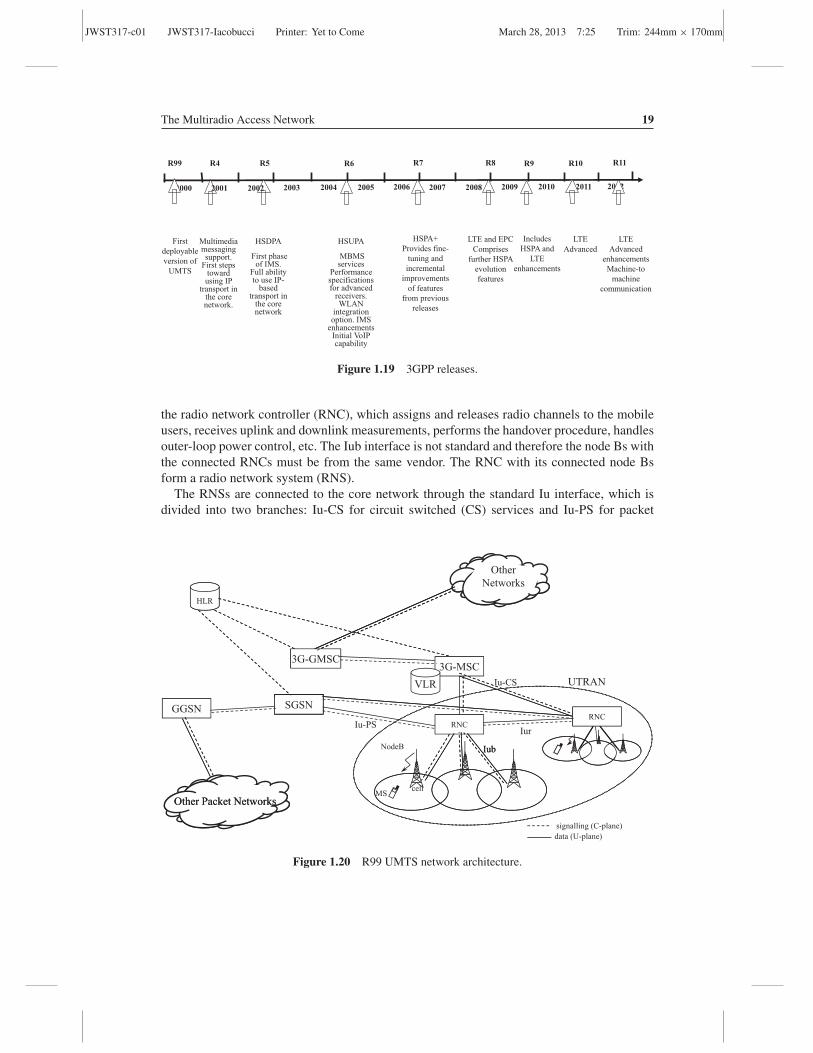
Figure 1.19 shows 3GPP releases from R99 to R11 with their principal characteristics. Itshows that 3GPP standardized UMTS, its evolution HSPA/HSPA+, LTE and LTE advanced.
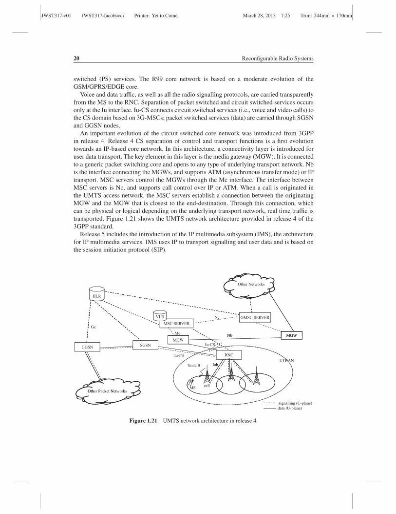
Figure 1.20 shows the UMTS network architecture standardized in release 99 (R99) of the3GPP standard. The UMTS network can be divided into an access network, called UMTSterrestrial radio access network (UTRAN), and a core network. UMTS R99 introduces a radioaccess network based on code division multiple access (CDMA) radio technology.
The mobile station (MS) communicates through a standardized radio interface with thenode B, which is a node equivalent to the BTS in GSM. Node B handles more than one cell,makes measurements over the uplink, broadcasts cell parameters and executes procedures likepaging and inner-loop power control. Each node B is connected, through the Iub interface, to
JWST317-c01 JWST317-Iacobucci Printer: Yet to Come March 28, 2013 7:25 Trim: 244mm × 170mm
The Multiradio Access Network 19
201120102009200820072006200520042003
R99 R4 R5 R6 R7 R8 R9 R10
First
deployable
version of
UMTS
Multimedia messaging support.
First steps toward using IP
transport in the core network.
HSDPA
First phase of IMS.
Full ability to use IP-
based transport in
the core network
HSUPA
MBMS services
Performance specifications for advanced
receivers. WLAN
integration option. IMS
enhancements Initial VoIP capability
HSPA+
Provides fine-
tuning and
incremental
improvements
of features
from previous
releases
2000 2001 2002
LTE and EPC
Comprises
further HSPA
evolution
features
Includes
HSPA and
LTE
enhancements
LTE
Advanced
R11
2012
LTE
Advanced
enhancements
Machine-to
machine
communication
Figure 1.19 3GPP releases.
the radio network controller (RNC), which assigns and releases radio channels to the mobileusers, receives uplink and downlink measurements, performs the handover procedure, handlesouter-loop power control, etc. The Iub interface is not standard and therefore the node Bs withthe connected RNCs must be from the same vendor. The RNC with its connected node Bsform a radio network system (RNS).
The RNSs are connected to the core network through the standard Iu interface, which isdivided into two branches: Iu-CS for circuit switched (CS) services and Iu-PS for packet
Other
Networks
HLR
3G-MSC
VLR
3G-GMSC
Iu-CS UTRAN
RNC
NodeB
SGSNGGSNRNC
IurIu-PS
Iub
MScell
Other Packet Networks
Iub
Other Packet Networks
signalling (C-plane)
data (U-plane)
Figure 1.20 R99 UMTS network architecture.
JWST317-c01 JWST317-Iacobucci Printer: Yet to Come March 28, 2013 7:25 Trim: 244mm × 170mm
20 Reconfigurable Radio Systems
switched (PS) services. The R99 core network is based on a moderate evolution of theGSM/GPRS/EDGE core.
Voice and data traffic, as well as all the radio signalling protocols, are carried transparentlyfrom the MS to the RNC. Separation of packet switched and circuit switched services occursonly at the Iu interface. Iu-CS connects circuit switched services (i.e., voice and video calls) tothe CS domain based on 3G-MSCs; packet switched services (data) are carried through SGSNand GGSN nodes.
An important evolution of the circuit switched core network was introduced from 3GPPin release 4. Release 4 CS separation of control and transport functions is a first evolutiontowards an IP-based core network. In this architecture, a connectivity layer is introduced foruser data transport. The key element in this layer is the media gateway (MGW). It is connectedto a generic packet switching core and opens to any type of underlying transport network. Nbis the interface connecting the MGWs, and supports ATM (asynchronous transfer mode) or IPtransport. MSC servers control the MGWs through the Mc interface. The interface betweenMSC servers is Nc, and supports call control over IP or ATM. When a call is originated inthe UMTS access network, the MSC servers establish a connection between the originatingMGW and the MGW that is closest to the end-destination. Through this connection, whichcan be physical or logical depending on the underlying transport network, real time traffic istransported. Figure 1.21 shows the UMTS network architecture provided in release 4 of the3GPP standard.
Release 5 includes the introduction of the IP multimedia subsystem (IMS), the architecturefor IP multimedia services. IMS uses IP to transport signalling and user data and is based onthe session initiation protocol (SIP).
HLR
Other Networks
GMSC-SERVER
MSC-SERVER
MGW
VLR
McNb
Nc
Gc
RNC
SGSNGGSN
Iu-PS
Iu-CS
MGWMGW
UTRAN
Nb
I bNode B
MScell
Oth P k t N t k
Iub
Other Packet Networks
signalling (C-plane)
data (U-plane)
Figure 1.21 UMTS network architecture in release 4.
JWST317-c01 JWST317-Iacobucci Printer: Yet to Come March 28, 2013 7:25 Trim: 244mm × 170mm
The Multiradio Access Network 21
1.2.4 UMTS/HSPA/HSPA+ Access Network
The UMTS/HSPA/HSPA+ access network includes mobile stations (MSs), node Bs, radionetwork controllers (RNCs) and related interfaces. The radio interface is based on codedivision multiple access (CDMA), in both FDD and TDD modes.
In the FDD mode, one band is assigned to the uplink and one different band is assigned tothe downlink. Each bandwidth is 5 MHz wide. In the TDD mode, a 5 MHz band is shared intime between the uplink and downlink. In most countries only UMTS FDD was installed.
1.2.4.1 CDMA Basics
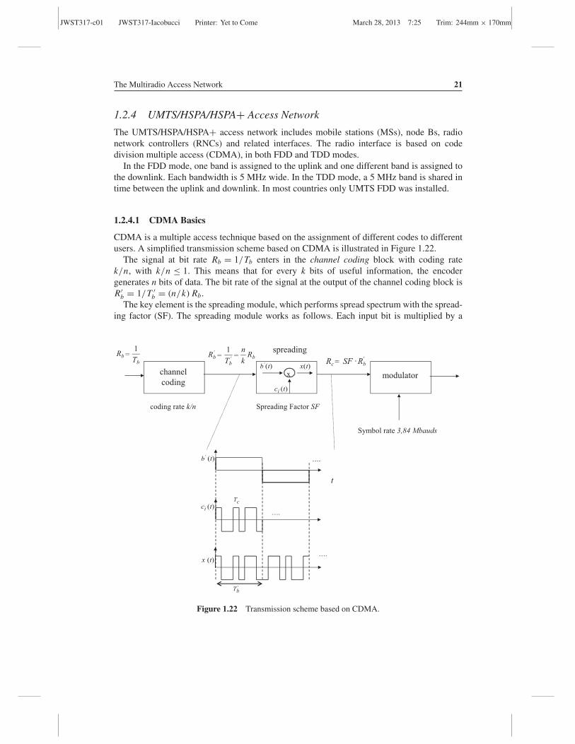
CDMA is a multiple access technique based on the assignment of different codes to differentusers. A simplified transmission scheme based on CDMA is illustrated in Figure 1.22.
The signal at bit rate Rb = 1/Tb enters in the channel coding block with coding ratek/n, with k/n ≤ 1. This means that for every k bits of useful information, the encodergenerates n bits of data. The bit rate of the signal at the output of the channel coding block isR′
b = 1/T ′b = (n/k) Rb.
The key element is the spreading module, which performs spread spectrum with the spread-ing factor (SF). The spreading module works as follows. Each input bit is multiplied by a
TbRb
1= = =
='RbSF ·Rc
channel
coding
spreading
modulator
coding rate k/n Spreading Factor SF
Symbol rate 3,84 Mbauds
Rbkn
TbRb '
' 1
x
x (t)
(t)b'
….
t
'
Tc
Tb
….
….
ci (t)
ci (t)
b (t)' x(t)
Figure 1.22 Transmission scheme based on CDMA.
JWST317-c01 JWST317-Iacobucci Printer: Yet to Come March 28, 2013 7:25 Trim: 244mm × 170mm
22 Reconfigurable Radio Systems
codeword (spreading code) having the duration of the bit but which is composed of a numberof chips equal to the SF. A chip is one of the pulses forming the codeword c (t).
Multiple access is achieved by assigning different spreading codes to different users. If thecodes are orthogonal and the transmission among the different users is synchronous, then eachsignal can be perfectly decoded. Two codes ci (t) and c j (t) are orthogonal if:
1
T ′b
∫
T ′b
ci (t) · c j (t)dt = E[ci (t) · c j (t)
] ∣∣T ′
b=
{1 if i = j
0 if i �= j(1.1)
The signal encoded with spreading code ci (t) is:
x(t) = b′(t) · ci (t) (1.2)
If N synchronous encoded signals having the same rate R′b are transmitted and neither noise
nor attenuation is taken into account, then the signal at the receiver side is the sum of the Nsignals:
z(t) =N∑
k=1
xk(t) =N∑
k=1
b′k(t) · ck (t) (1.3)
To decode the bit b′i transmitted from the ith user during the interval T ′
b , the received signalz(t) is multiplied by ci (t) and then the obtained signal is averaged in T ′
b:
E [z(t) · ci (t)]∣∣∣T ′
b= 1
T ′b
∫
T ′b
(N∑
k=1
xk(t)
)ci (t) dt = 1
T ′b
∫
T ′b
(N∑
k=1
b′kck(t)
)ci (t) dt
=N∑
k=1
b′k
1
T ′b
∫
T ′b
ck(t)ci (t) dt = b′i (1.4)
Equation (1.4) shows that with orthogonal codes and synchronous transmissions, thetransmitted signals can be perfectly decoupled. If pseudo-orthogonal codes are used, or thetransmitted signals are not synchronous, then an interference component must be taken intoaccount. The encoded signal, which has rate Rc = SF · R′
b, goes into the modulator. The
modulator clock is 3.84 MHz (3.84 × 10⁶ modulation symbols per second), obtained byconsidering a carrier of 5 MHz and a 0.3 roll-off filter factor.
In UMTS, two families of codes are used: the perfectly orthogonal channellization codes(Walsh–Hadamard codes) and the pseudo-orthogonal codes. Channellization codes have avariable spreading factor (SF) according to R′
b and the rate k/n. They are also called orthogonalvariable spreading factor (OVSF) codes, channellization codes or spreading codes, and increasethe amplitude of the transmission band.
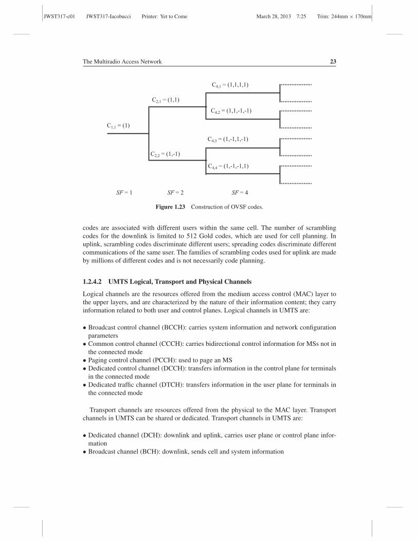
Figure 1.23 shows the construction of OVSF codes. The length of OVSF codes is always apower of two. Pseudo-orthogonal codes are scrambling codes and do not change the transmis-sion bandwidth. In downlink, scrambling codes are associated with different cells; spreading
JWST317-c01 JWST317-Iacobucci Printer: Yet to Come March 28, 2013 7:25 Trim: 244mm × 170mm
The Multiradio Access Network 23
SF = 1 SF = 2 SF = 4
C2,1 = (1,1)
C2,2 = (1,-1)
C1,1 = (1)
C4,1 = (1,1,1,1)
C4,2 = (1,1,-1,-1)
C4,3 = (1,-1,1,-1)
C4,4 = (1,-1,-1,1)
Figure 1.23 Construction of OVSF codes.
codes are associated with different users within the same cell. The number of scramblingcodes for the downlink is limited to 512 Gold codes, which are used for cell planning. Inuplink, scrambling codes discriminate different users; spreading codes discriminate differentcommunications of the same user. The families of scrambling codes used for uplink are madeby millions of different codes and is not necessarily code planning.
1.2.4.2 UMTS Logical, Transport and Physical Channels
Logical channels are the resources offered from the medium access control (MAC) layer tothe upper layers, and are characterized by the nature of their information content; they carryinformation related to both user and control planes. Logical channels in UMTS are:
• Broadcast control channel (BCCH): carries system information and network configurationparameters
• Common control channel (CCCH): carries bidirectional control information for MSs not inthe connected mode
• Paging control channel (PCCH): used to page an MS• Dedicated control channel (DCCH): transfers information in the control plane for terminals
in the connected mode• Dedicated traffic channel (DTCH): transfers information in the user plane for terminals in
the connected mode
Transport channels are resources offered from the physical to the MAC layer. Transportchannels in UMTS can be shared or dedicated. Transport channels in UMTS are:
• Dedicated channel (DCH): downlink and uplink, carries user plane or control plane infor-mation
• Broadcast channel (BCH): downlink, sends cell and system information
JWST317-c01 JWST317-Iacobucci Printer: Yet to Come March 28, 2013 7:25 Trim: 244mm × 170mm
24 Reconfigurable Radio Systems
• Forward access channel (FACH): downlink, used for signalling and data• Paging channel (PCH): downlink, carries paging• Random access channel (RACH): uplink, carries control information between the MS and
eNB (evolved node B); is subject to collisions
Physical channels are the resources used for transmission over the radio interface. They aredefined by a carrier frequency, a forward error correction (FEC) code, a scrambling code anda spreading code. Physical channels are:
• Physical random access channel (PRACH): uplink, carries random access preambles duringthe random access procedure
• Dedicated physical channel (DPCH): uplink and downlink, carries signalling (dedicatedphysical control channel, or DPCCH) and data (dedicated physical data channel, or DPDCH)dedicated to a connection
• Primary common control physical channel (PCCPCH): downlink, carries BCH• Secondary common control physical channel (SCCPCH): downlink, carries PCH and FACH
Figure 1.24 shows downlink and uplink channels at logical, transport and physical layersand their mapping. In the figure are also shown the following channels:
• Synchronization channel (SCH): downlink, to synchronize the mobile stations to the network• Indicator channels (ICHs): signalling entities with Boolean value
Examples of indicators are:
• Acquisition indicator channel (AICH): downlink, for the response to the preamble in thePRACH
• Paging indicator channel (PICH): downlink, indicates to the MS in the sleep mode to listento the paging channel in the subsequent frame; the sleep mode is a discontinuous receptionmode to save batteries
When an MS switches on, it searches and selects one cell through the synchronization signals,then derives system information from the PCCPCH, executes the random access procedureand sends signalling to register to the network.
Figure 1.25 shows an example with the use of logical, transport and physical channels inthe radio resource control (RRC) connection setup procedure. The RRC protocol performsallocation and release of the radio resources, admission and congestion control, etc. It is atlayer 3 in the control plane protocol stack.
1.2.4.3 UMTS Modulations
The FDD version of UMTS uses quadrature phase shift keying (QPSK) modulation in downlinkand dual binary phase shift keying (BPSK) modulation in uplink. Dedicated physical channelsDPDCH and DPCCH are multiplexed in time in downlink, and each constellation symbolcarries DPDCH or DPCCH, transmitted with the same SF (from 4 to 512). In uplink, the

JWST317-c01 JWST317-Iacobucci Printer: Yet to Come March 28, 2013 7:25 Trim: 244mm × 170mm
CC
CH
D
CC
H/D
TC
H
Logi
cal
uplin
k C
hann
els
Tran
spor
t up
link
chan
nels
RA
CH
DP
CH
P
RA
CH
DC
H
Phys
ical
up
link
chan
nels
PC
CH
B
CC
H
CC
CH
D
CC
H/D
TC
H
Logi
cal
dow
nlin
k C
hann
els
PC
H
FA
CH
SC
CP
CH
BC
H
DC
H
PC
CP
CH
D
PC
H
Tran
spor
t do
wnl
ink
chan
nels
Phys
ical
do
wnl
ink
chan
nels
S
CH
IC
Hs
…
Fig
ure
1.24
Log
ical
,tra
nspo
rtan
dph
ysic
alch
anne
lsm
appi
ng.
25

JWST317-c01 JWST317-Iacobucci Printer: Yet to Come March 28, 2013 7:25 Trim: 244mm × 170mm
26 Reconfigurable Radio Systems
[CCCH:RACH] RRC CONNECTION REQUEST
MS UTRAN
Physical channel PRACH
[CCCH:FACH] RRC CONNECTION SETUP
Physical channel SCCPCH
[DCCH:DCH] RRC CONNECTION SETUP COMPLETE
Physical channel DPCH
Figure 1.25 Example of the RRC connection setup procedure.
I-branch carries DPCCH (with fixed SF = 256) and the Q-branch carries DPDCH (with avariable SF from 4 to 256). Figure 1.26 shows the modulations in the UMTS FDD mode.
In uplink, to maintain the synchronization between MS and BTS, DPCCH is transmitted alsoduring DPDCH pauses. The physical resources are allocated in UMTS for an interval calledthe transmission time interval (TTI). The shortest TTI is 10 ms, but it can also be of 20 ms,40 ms and 80 ms. In UMTS, information is structured in frames of 10 ms and 15 time slots.
FDD DL: QPSK
Q-Branch
I-Branch
each constellation symbol is dedicated to
DPCCH or DPDCH
FDD UL: Dual BPSK
Q-Branch
I-Branch
DPDCH
DPCCH
Figure 1.26 Modulations in the UMTS FDD mode.

JWST317-c01 JWST317-Iacobucci Printer: Yet to Come March 28, 2013 7:25 Trim: 244mm × 170mm
The Multiradio Access Network 27
1.2.4.4 HSPA
High speed packet access (HSPA) is the UMTS evolution for high bit rate data transmission.It can be divided into its downlink and uplink versions: high speed downlink packet access(HSDPA) and high speed uplink packet access (HSUPA).
HSDPA has been introduced in release 5 of the 3GPP standard and includes:
• Addition of 16-QAM (quadrature amplitude modulation) to the QPSK;• Adaptive modulation and coding (AMC), with peak bit rate up to 14.4 Mbit/s;• Fixed spreading factor SF = 16 and multicode transmission;• Introduction of new radio channels; and• Some RNC functionalities are moved to node B.
HSDPA introduces a new transport channel, the high speed downlink shared channel(HS-DSCH), where the TTI is reduced at 2 ms. Different users can be multiplexed in adjacentTTIs in the same HS-DSCH. The HS-DSCH is mapped at the physical layer into the highspeed physical downlink shared channel (HS-PDSCH).
In the uplink, an acknowledgement of the radio block (ACK/NACK) is carried in a physicaldedicated control channel, the high speed dedicated physical control channel (HS-DPCCH).The HS-DPCCH also carries the channel quality indicator (CQI), corresponding to the mod-ulation and coding scheme (MCS) and transport block size (TBS), for which the estimatedreceived downlink transport block error rate (BLER) shall not exceed 10%. TBS is the amountof data carried in a TTI.
Figure 1.27 shows that different users are multiplexed in the HS-DSCH with 2 ms TTIs. Inthe uplink, the HS-DPCCH carries ACK/NACKs and CQIs.
~19200 chip (5 ms)
HS-DSCH (downlink)
ReceptionUser side
time
TransmissionUser side
HS-DPCCH (uplink)
Reception Node B side
Block 1
Block 2
Block 3
Block 4
Block 5 Block 6 Block 1
Block 7
TTI (2 ms)
Elaboration
NACK ACK ACKACKCQI CQI KKK KKKCQI CQI CQIACK
Figure 1.27 HSDPA transmission on the HS-DSCH and feedbacks.

JWST317-c01 JWST317-Iacobucci Printer: Yet to Come March 28, 2013 7:25 Trim: 244mm × 170mm
28 Reconfigurable Radio Systems
PCCPCHReception User Side
1 frame = 15 Time Slot = 10 ms
HS-SCCH
1 TTI = 3 Time Slot = 2 ms
HS-DSCH
1 TTI = 3 Time Slot = 2 ms
2 Time Slot = 1,33 ms
Part 1: MS, CCS,
UE ID
Part 2: TBS,
HARQ
Figure 1.28 Scheduling information in HSDPA.
Scheduling information is carried in a new downlink shared control channel, the high speedshared control channel (HS-SCCH). It uses a code with SF = 128 and sends, in an interval of2 ms, the transport format (TF), which represents the information needed to demodulate anddecode (modulation and coding scheme, transport block size) the data sent to a mobile stationon the HS-DSCH. In particular, scheduling information is divided into two parts:
• Part 1: lasts for one time slot and carries the information necessary to demodulate the HS-DSCH. It contains the mobile station MAC identifier, the modulation and the channellizationcode Set (CCS), which identifies the assigned spreading codes.
• Part 2: is superimposed on to the HS-DSCH and carries the information necessary to decodethe HS-DSCH, like the transport block size (TBS) and the hybrid automatic repeat request(HARQ) scheme.
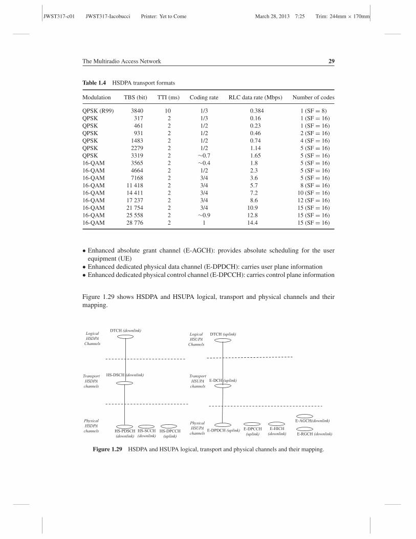
Figure 1.28 shows the HS-SCCH carrying scheduling information.Table 1.4 shows some examples of transport formats. The first row shows the R99 transport
format for the 384 kbps bit rate. The last row shows that, in order to reach the maximum bitrate of 14.4 Mbps, the whole cell capacity must be assigned to a single user (15 codes withSF = 16) with 16 QAM modulation and no encoding (coding rate = 1).
HSUPA uses most features of UMTS R99. It has been introduced in release 6 of the 3GPPstandard and provides:
• Adaptive encoding, with multicode transmission and a peak bit rate up to 5.76 Mbps• Some RNC functionalities are moved to node B
A new dedicated transport channel, the enhanced dedicated channel (E-DCH), has been intro-duced. It supports multicode transmission and adaptive encoding. To support HSUPA, thefollowing physical channels have been added to the radio interface:
• Enhanced HARQ indicator channel (E-HICH): downlink, used to send HARQ ACKs• Enhanced relative grant channel (E-RGCH): provides relative step up/down scheduling
commands
JWST317-c01 JWST317-Iacobucci Printer: Yet to Come March 28, 2013 7:25 Trim: 244mm × 170mm
The Multiradio Access Network 29
Table 1.4 HSDPA transport formats
Modulation TBS (bit) TTI (ms) Coding rate RLC data rate (Mbps) Number of codes
QPSK (R99) 3840 10 1/3 0.384 1 (SF = 8)QPSK 317 2 1/3 0.16 1 (SF = 16)QPSK 461 2 1/2 0.23 1 (SF = 16)QPSK 931 2 1/2 0.46 2 (SF = 16)QPSK 1483 2 1/2 0.74 4 (SF = 16)QPSK 2279 2 1/2 1.14 5 (SF = 16)QPSK 3319 2 ∼0.7 1.65 5 (SF = 16)16-QAM 3565 2 ∼0.4 1.8 5 (SF = 16)16-QAM 4664 2 1/2 2.3 5 (SF = 16)16-QAM 7168 2 3/4 3.6 5 (SF = 16)16-QAM 11 418 2 3/4 5.7 8 (SF = 16)16-QAM 14 411 2 3/4 7.2 10 (SF = 16)16-QAM 17 237 2 3/4 8.6 12 (SF = 16)16-QAM 21 754 2 3/4 10.9 15 (SF = 16)16-QAM 25 558 2 ∼0.9 12.8 15 (SF = 16)16-QAM 28 776 2 1 14.4 15 (SF = 16)
• Enhanced absolute grant channel (E-AGCH): provides absolute scheduling for the userequipment (UE)
• Enhanced dedicated physical data channel (E-DPDCH): carries user plane information• Enhanced dedicated physical control channel (E-DPCCH): carries control plane information
Figure 1.29 shows HSDPA and HSUPA logical, transport and physical channels and theirmapping.
DTCH (uplink) Logical HSUPA
Channels
Transport HSUPA
channels
E-DPDCH (uplink)
E-DCH (uplink)
Physical HSUPA
channels
DTCH (downlink) Logical HSDPA
Channels
HS-DSCH (downlink)
HS-PDSCH
(downlink)
Transport HSDPA
channels
Physical HSDPA
channels E-DPCCH
(uplink)
E-AGCH(downlink)
E-RGCH (downlink) HS-SCCH
(downlink) HS-DPCCH
(uplink)
E-HICH
(downlink)
Figure 1.29 HSDPA and HSUPA logical, transport and physical channels and their mapping.

JWST317-c01 JWST317-Iacobucci Printer: Yet to Come March 28, 2013 7:25 Trim: 244mm × 170mm
30 Reconfigurable Radio Systems
Table 1.5 HSPA and HSPA+ principal features
DL UL
3GPP RLC bit rate RLC bit raterelease Features (Mbps) Features (Mbps)
R6 16-QAM 14.4 Dual BPSK 5.76R7 64-QAM 21.1 16-QAM 11.5
16-QAM, 2 × 2 MIMO 28.8 16-QAM 11.5R8 64-QAM, 2 × 2 MIMO 42.2 16-QAM 11.5R9 64-QAM, 2 × 2 MIMO, dual
carrier (10 MHz)84 16-QAM, dual carrier 23
R10 64-QAM, 2 × 2 MIMO, fourcarrier aggregation(20 MHz)
168 16-QAM, dual carrier 23
R11 64-QAM, 4 × 4 MIMO, fourcarrier aggregation(20 MHz)
336 64-QAM, dual carrier,2 × 2 MIMO
69
1.2.4.5 HSPA+The evolved high speed packet access is also called HSPA+ and has been standardized startingfrom release 7. It introduces new features at the physical layer to increase the maximumuplink (UL) and downlink (DL) bit rates and new features at the MAC layer to enhance packetconnectivity performances.
The principal features introduced at the physical layer up to release 11 are:
• Higher order QAMs: used to increase uplink and downlink bit rates.• Multiple input multiple output (MIMO) antennas: used to enhance the received signal to
noise ratio (SNR) or to multiply the bit rate. An introduction to MIMO is given in Section1.2.6.4 of this book.
• Carrier aggregation: more carriers of 5 MHz each are aggregated to multiply the bit rate.
Table 1.5 shows the features introduced in HSPA+ up to 3GPP release 11.
1.2.5 LTE Network Architecture
LTE is a new system standardized by 3GPP. The work on LTE started with a workshop inToronto, on 2 and 3 November 2004. During the workshop, manufacturers, researchers andoperators contributed to identify the high level requirements for the evolution of UTRAN.The focus was mainly on the radio access with several proposals for radio evolution. FromDecember 2004 to June 2006 feasibility studies on the LTE system were conducted.
LTE requirements, identified from the beginning, concerned services (support of voice andmultimedia over IP, high uplink and downlink bit rates, low latency), radio performances(scalable bandwidth, usage of MIMO to improve the throughput), costs (simplified networkarchitecture, transport of user plane and control plane over IP) and interworking with existingradiomobile networks [6].

JWST317-c01 JWST317-Iacobucci Printer: Yet to Come March 28, 2013 7:25 Trim: 244mm × 170mm
The Multiradio Access Network 31
The detailed standard work started in June 2007. The 3GPP goal was ‘to develop a frameworkfor the evolution of the 3GPP radio-access technology towards a high-data-rate, low-latencyand packet-optimized radio-access technology’.
In parallel to the project for the definition of LTE radio access, a 3GPP project related to thecore network started. The project was called system architecture evolution (SAE) with the aimof standardizing the evolved packet core (EPC). EPC is an all IP network which supports notonly the LTE access but also other 3GPP (GSM/GPRS/EDGE, UMTS/HSPA/HSPA+) andnon-3GPP (WLAN (wireless local area network), WiMAX, etc.) access networks.
At the end of 2008 the 3GPP release 8 was completed. It specifies LTE OFDMA-basedaccess and defines the EPC. Because EPC is an all IP network, it does not support voice unlessthe IP multimedia subsystem (IMS) is implemented.
Two functionalities for the voice service are defined:
• Radio voice call continuity (RVCC). This functionality provides that a VoIP (voice overIP)/IMS service using the LTE radio access moves, if necessary, from the LTE packetswitched domain to the 2G or 3G circuit switched domain.
• Circuit switched fallback (CSFB). This functionality does not need IMS and enables circuitswitched voice for LTE devices. When an LTE mobile station makes or receives a voice call,it moves (‘falls back’) to the 3G or 2G network to serve the call.
Home evolved node B (H-eNB) is supported by 3GPP release 8. Release 9 appeared at the endof 2009, introducing enhancements to HSPA and LTE release 8. Release 10 appeared in 2011and introduced features for LTE advanced.
Figure 1.30 shows the LTE network architecture with its access network, called evolvedUTRAN (E-UTRAN), and the evolved packet core (EPC). From the figure is clear that thenetwork structure is extremely simplified. In fact, the only node in the access network is theevolved node B (eNB), which includes the functions of the base station and its controller.
The eNB main functionalities are:
• Radio resource management: radio bearer control, radio admission control, scheduling ofresources in uplink and downlink, retransmission handling,
• Mobility management,• IP header compression and encryption of user data,• Selection of a mobility management entity (MME) at the UE attachment, if the UE does not
provide this information,• Routing of user data to a gateway,• Scheduling and transmission of control messages (paging, broadcast), and• Measurement and measurement reporting configuration for mobility and scheduling.
The eNBs are interconnected through the X2 interface, which carries both data (user plane)and signalling (control plane).
In the EPC, signalling and data are separated and managed by different nodes. The MME isconnected to the eNBs through the S1-MME interface, which carries control plane messages.The system architecture evolution gateway (SAE GW) is connected to the eNBs through theS1-U interface, which carries user plane messages. The home subscriber server (HSS) is therepository of all permanent user data, like the subscriber profile and the permanent key forauthentication, ciphering and integrity protection. It also stores the location of the user at thelevel of visited network control node, such as MME.

JWST317-c01 JWST317-Iacobucci Printer: Yet to Come March 28, 2013 7:25 Trim: 244mm × 170mm
32 Reconfigurable Radio Systems
eNB
eNB eNB
eNB
X2
MME SAE GW
S1-U S1-MME
S11
EPC
E-UTRAN
signalling (C-plane)
data (U-plane)
HSS
S6a
Other Networks
PCRF
Gx
Figure 1.30 LTE network architecture.
The MME manages mobility, MS identities and security parameters. The principal functionsof the MME are:
• It executes tracking and paging procedures and assigns temporary identities.• During the attach (registration) procedure, it receives the attach request message from the
eNB and forwards to the SAE GW the ‘create default bearer request’.• It is involved in intra-LTE handover, which includes a core network node reallocation.• It executes authentication and ciphering procedures.
Contextual with the registration, a connection called the default bearer is set up and an IPaddress is assigned to the MS.
The SAE gateway can be separated into two gateways: the serving gateway (SGW) andthe packet gateway (PGW). The primary task of the SGW is IP routing and forwarding of IPpackets. It is the user plane anchor for inter-eNB handover and when the user moves among3GPP access technologies. The PGW is connected to the SGW and to the external networks. Itis responsible for the QoS and is the user plane anchor when the MS moves among 3GPP andnon-3GPP radio access technologies. One MS can have simultaneous access to more than onePGW (e.g., to have access to different packet data networks). The SAE gateway also performspacket filtering and IP address allocation to mobile stations.

JWST317-c01 JWST317-Iacobucci Printer: Yet to Come March 28, 2013 7:25 Trim: 244mm × 170mm
The Multiradio Access Network 33
The last element included in the EPC is the policy and charging resource function (PCRF),connected with the Gx interface (signalling only) to the PGW. It implements policy andcharging rules and elaborates policy and charging control requests. The EPC can be easilyintegrated with both 3GPP and non-3GPP access networks, such as fixed broadband, wirelessLANs, WiMAX, etc. It allows full mobility among 3GPP access networks and roaming amongother access networks. The EPC is an IP-based core network; it does not natively support voiceand multimedia.
The initial development of LTE does not support voice service, unless the network operatorimplements the IP multimedia subsystem (IMS). Release 8 of the 3GPP standard introducesthe circuit switched fallback (CSFB) procedure, which provides a mobile station camped onLTE to be served, for the voice service, from the other existing 3G or 2G access networks.This requires 2G/3G coverage and a new interface, the SGW, between the MME and the MSCserver.
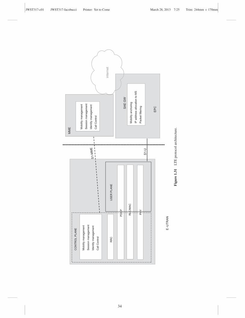
Figure 1.31 shows the protocol architecture implemented in LTE network nodes. The radioprotocol stack in eNBs includes:
• Physical layer (PHY): involves both user and control planes and performs synchronization,channel coding, interleaving, mo-demodulation, multiplexing, measurement and measure-ment reporting.
• Medium access control (MAC): involves both user and control planes and performs channelaccess control mechanisms, packet queuing, priority handling. It is the lower part of thesecond layer in the protocol stack.
• Radio link control (RLC): handles flow control, segmentation, error control, retransmissions.It is the upper part of the second layer in the protocol stack.
• Packet data convergence protocol (PDCP): performs IP header compression for radio trans-mission in the user plane (UP) and encryption and integrity protection in the control plane(CP).
• Radio resource control (RRC): in the control plane, performs allocation and release of theradio resources, admission and congestion control, and intercell radio resource management.It is at layer 3 in the CP protocol stack.
Other protocols related to the control plane, but not related to the radio interface, are imple-mented in eNBs and MMEs. Such protocols provide nonaccess stratum (NAS) functionalitiesand are mobility management (MM), session management (SM), call control (CC) and identitymanagement (IM).
1.2.6 LTE Access Network
The LTE access network is the E-UTRAN, which as a flat architecture of interconnectedevolved node Bs (eNBs). The LTE radio interface is based on the following enablingtechnologies:
• OFDMA (orthogonal frequency division multiple access): used for downlink (from eNBto MS),
• SC-FDMA (single carrier FDMA): used for uplink (from MS to eNB),• MIMO (multiple input multiple output) antennas,
JWST317-c01 JWST317-Iacobucci Printer: Yet to Come March 28, 2013 7:25 Trim: 244mm × 170mm
inte
rnet
PH
Y
MM
E
E-U
TRA
N
SA
E G
W
S1-
U
EP
C
RLC
/MA
C
RR
C
Mob
ility
man
agem
ent
Ses
sion
man
agem
ent
Iden
tity
man
agem
ent
Cal
l Con
trol
CO
NTR
OL
PLA
NE
US
ER
PLA
NE
Mob
ility
anc
horin
g
IP a
ddre
ss a
lloca
tion
to M
S
Pac
ket f
ilter
ing
Mob
ility
man
agem
ent
Ses
sion
man
agem
ent
Iden
tity
man
agem
ent
Cal
l Con
trol
PD
CP
Fig
ure
1.31
LTE
prot
ocol
arch
itect
ure.
34

JWST317-c01 JWST317-Iacobucci Printer: Yet to Come March 28, 2013 7:25 Trim: 244mm × 170mm
The Multiradio Access Network 35
• Multicarrier channel-dependent resource scheduling, and• Fractional frequency reuse.
In the following paragraphs are presented the main features of the LTE radio interface.
1.2.6.1 OFDM and OFDMA
OFDMA, which stands for orthogonal frequency division multiple access, is a multiple accesstechnique based on orthogonal frequency division multiplexing (OFDM) modulation, a par-ticular case of multicarrier transmission. In OFDM a high bit rate bit stream is split into lowbit rate multiple streams, each of which is transmitted on a separated subcarrier.
OFDM subcarriers (unlike FDM) are formed to partially overlap, allowing a considerablesaving in terms of bandwidth. OFDM presents the following advantages:
• The usage of orthogonal subcarriers eliminates noises due to partial spectra overlapping.• An OFDM signal is the sum of PSK or QAM modulated signals in each subcarrier.• OFDM is robust in an environment with frequency selective fading.• OFDM is robust against narrowband interference.• In slowly time-varying channels, it is possible to adjust the rate of each subcarrier in the
function of the signal to noise ratio (SNR) at the receiver side.• OFDM makes possible single frequency networks.• OFDM makes possible scalable bandwidth.
In OFDMA, multiple access among different users is achieved by assigning to each user agroup of subcarriers in certain slots of time.
Figure 1.32 shows the difference between OFDM and OFDMA: in OFDM each usertransmits using all subcarriers; in OFDMA the subcarriers are shared, at the same time, amongdifferent users. A user can transmit over contiguous or noncontiguous subcarriers. LTE usesODFMA for downlink multiple access.
time
Su
b-carriers
OFDM OFDMA
time
Su
b-carriers
Figure 1.32 OFDM and OFDMA.

JWST317-c01 JWST317-Iacobucci Printer: Yet to Come March 28, 2013 7:25 Trim: 244mm × 170mm
36 Reconfigurable Radio Systems
900
)(tu
}Σ∞
–∞=
−+=n
tfjπnn
cenTtujb ){(atX 2)(Re)(
)(tu
t)fccos (2π
t)fcsin (2π
na
nb
Figure 1.33 QAM modulator scheme.
1.2.6.2 OFDM Basics
OFDM is a multicarrier modulation where a high bit rate bit stream is split into multiplestreams at low bit rates, each of which is QAM-modulated on a separated subcarrier.Figure 1.33 shows the QAM-modulator scheme.
The QAM-modulated signal is:
X (t) =∞∑
n=−∞Re
{(an + jbn) u(t − nT )e j2π fc t
}(1.5)
where T is the symbol time, (an + jbn) is the QAM symbol transmitted at nth symbol time,u (t) is a filter that satisfies the Nyquist condition for the absence of intersymbol interferenceand fc is the carrier frequency. A multicarrier signal is generated by summing N QAMmodulated signals:
X (t) = Re
{N−1∑i=0
Xi (t)
}= Re
{ ∞∑n=−∞
N−1∑i=0
[Xn,i u(t − nT )e j2π fi t
]}(1.6)
where T is the symbol time, Xn,i = an,i + jbn,i is the symbol transmitted over the ith subcarrierat nth symbol time and fi is the ith subcarrier.
Two different subcarriers (i and j) are orthogonal if:
1
T
∞∫
−∞u (t)e j2π fi t · u (t) e j2π f j t dt =
{1 i = j
0 i �= j(1.7)
In OFDM the subcarriers are spaces of � f = 1/
T . If fi = f0 + 1/T , Equation (1.6) can bewritten as follows:
X (t) = Re
{N∑
i=1
Xi (t)
}=
∞∑n=−∞
Re
{u(t − nT )e j2π f0t
N−1∑i=0
{Xn,i e
j2π t(i/T )}}
(1.8)

JWST317-c01 JWST317-Iacobucci Printer: Yet to Come March 28, 2013 7:25 Trim: 244mm × 170mm
The Multiradio Access Network 37
Observe that the component:
Xbb (t) =N−1∑i=0
{Xn,i e
j2π t(i/T )}
is the equivalent baseband signal at the nth symbol time and is an inverse Fourier transform.If Xbb (t) is sampled at kT/N intervals, the following discrete sequence is obtained:
xn,k =N−1∑i=0
{Xn,i e
j2π i(k/N )}, k = 0, . . . ,N − 1 (1.9)
Equation (1.9) is the expression of the inverse discrete Fourier transform (IDFT) of themodulation symbols at time n:
{Xn,1 Xn,2 . . . Xn,N
}, less than a scale factor N. The sequence{
xn,1 xn,2 . . . xn,N}, transmitted in a symbol time T at kT/N intervals, is called the OFDM
symbol.Equation (1.8) suggests an equivalent implementation of a multicarrier modulation with an
inverse fast Fourier transform (IFFT) operation in the baseband section of the modulator. Theequivalent modulator scheme is shown in Figure 1.34.
At the transmission side, in the symbol time n, N symbols Xi are put as input to theIFFT block to generate the OFDM symbol {x1 x2 . . . xN }. Then there is a transformation fromparallel to serial (at time distance T/N) and, through a digital to analogue converter, two signals(the real and imaginary component of the sequence of {xi }) are generated and modulated atfrequency f0.
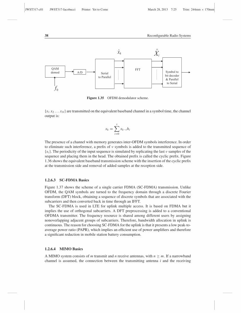
At the reception side, the f0 carrier is demodulated and an estimate of the real and imaginaryparts of the transmitted signal is derived. The sequence of {x̂i} is obtained by sampling thereceived signal at step T/N. Then the fast Fourier transform (FFT) operation returns an estimateof the QAM symbol transmitted on each subcarrier. The corresponding demodulator schemeis shown in Figure 1.35.
In an equivalent digital baseband transmission model, a channel can be modelled in thetime domain through an FIR (finite impulse response) filter with ν + 1 taps: h0h1 . . . hν . If
iX
0f
Bit
to Symbol
Encoder
IFFT
Parallel to Serial
D/AQAM
modulator
kx
Figure 1.34 OFDM modulator scheme.
JWST317-c01 JWST317-Iacobucci Printer: Yet to Come March 28, 2013 7:25 Trim: 244mm × 170mm
38 Reconfigurable Radio Systems
A/DFFT
Serial
to Parallel
xk∧ ∧
0f
QAM
demod
Xi
Symbol to
bit decoder
& Parallel
to Serial
Figure 1.35 OFDM demodulator scheme.
{x1 x2 . . . xN } are transmitted on the equivalent baseband channel in a symbol time, the channeloutput is:
xk =ν∑
i=0
xk−i hi
The presence of a channel with memory generates inter-OFDM symbols interference. In orderto eliminate such interference, a prefix of ν symbols is added to the transmitted sequence of{xi }. The periodicity of the input sequence is simulated by replicating the last ν samples of thesequence and placing them in the head. The obtained prefix is called the cyclic prefix. Figure1.36 shows the equivalent baseband transmission scheme with the insertion of the cyclic prefixat the transmission side and removal of added samples at the reception side.
1.2.6.3 SC-FDMA Basics
Figure 1.37 shows the scheme of a single carrier FDMA (SC-FDMA) transmission. UnlikeOFDM, the QAM symbols are turned to the frequency domain through a discrete Fouriertransform (DFT) block, obtaining a sequence of discrete symbols that are associated with thesubcarriers and then converted back in time through an IFFT.
The SC-FDMA is used in LTE for uplink multiple access. It is based on FDMA but itimplies the use of orthogonal subcarriers. A DFT preprocessing is added to a conventionalOFDMA transmitter. The frequency resource is shared among different users by assigningnonoverlapping adjacent groups of subcarriers. Therefore, bandwidth allocation in uplink iscontinuous. The reason for choosing SC-FDMA for the uplink is that it presents a low peak-to-average power ratio (PAPR), which implies an efficient use of power amplifiers and thereforea significant reduction in mobile station battery consumption.
1.2.6.4 MIMO Basics
A MIMO system consists of m transmit and n receive antennas, with n ≥ m. If a narrowbandchannel is assumed, the connection between the transmitting antenna i and the receiving

JWST317-c01 JWST317-Iacobucci Printer: Yet to Come March 28, 2013 7:25 Trim: 244mm × 170mm
1x1X
Bit
to S
ym
bo
l
En
cod
er
& S/P
IFF
T
Par
alle
l to
Ser
ial
Eq
uiv
alen
t
Dig
ital
Ch
ann
el
NN
Nx
xx
xx
^2
^1
^^
^..
...
ν−
NXNxNxν −
Nx {C
ycl
ic p
refi
x
νhh
h..
.1
0
Rem
ov
al o
f th
e
cycl
ic p
refi
x a
nd
Ser
ial
to P
aral
lel
1x Nx^^
FF
T
1
∧ XS
ym
bo
l to
bit
dec
od
er
& P/S
NX∧
Fig
ure
1.36
Equ
ival
entO
FDM
base
band
tran
smis
sion
sche
me
with
cycl
icpr
efix.
39

JWST317-c01 JWST317-Iacobucci Printer: Yet to Come March 28, 2013 7:25 Trim: 244mm × 170mm
40 Reconfigurable Radio Systems
iX
Bit
to Symbol
Encoder
& S/P
DFT
Subcarrier
mapping
IFFT
Parallel/Series
cyclic
prefix
equivalent baseband channel
time domain frequency domain time domain
Removal of the
cyclic prefix &
S/P
FFT
equalizer
IDFT
iX^
Symbol to
bit decoder
&
P/S
time domain frequency domain time domain
Figure 1.37 SC-FDMA transmission scheme.
antenna j can be expressed through a component hij and the MIMO system can be modelledas shown in Figure 1.38.
If si is the signal at the ith transmitting antenna (i = 1, 2, . . . , m), the signal at the jth (j =1, 2, . . . , n) receiving antenna is:
y j = h j1s1 + h j2s2 + · · · + h j sm + n j (1.10)
where n j is the received noise component at the jth antenna.
1s
1mh
11h1y
ny
mh1
m nhms
nmnmnnn
mm
nshshshy
nshshshy
+++=
+++=
...
...
....
...
2211
112121111
nsHy +=
Figure 1.38 MIMO model.

JWST317-c01 JWST317-Iacobucci Printer: Yet to Come March 28, 2013 7:25 Trim: 244mm × 170mm
The Multiradio Access Network 41
In a MIMO system three techniques live together:
• Diversity• Spatial multiplexing• Beamforming
DiversityThe diversity technique can be applied at both the transmitter side and the receiver side. Thepurpose of diversity is to improve the quality of the received signal, namely having a highersignal to noise ratio (SNR) at the receiver side.
Because of different transmission paths, the receiver sees differently faded signals. Themost used techniques for the diversity at the receiver side are:
• Switched diversity, which always chooses the strongest signal,• Equal gain combining (EGC), which coherently sums the received signals, and• Maximum ratio combining (MRC), which optimally combines the received signals, where
the signals are weighted proportionally to their signal to noise ratio.
The receive diversity does not require the compliance to a standard.In the diversity at the transmission side, copies of the same signal, differently encoded,
are sent through the transmitting antennas. Space–time codes are used for transmit diversity,where multiple copies of the signal are transmitted from different antennas at different times.Alamouti developed a two-branch transmit diversity scheme with two transmitting and tworeceiving antennas [7]. Pseudo-Alamouti coding schemes have been developed for multipleantennas.
BeamformingBeamforming is a technique that creates a directional radiation pattern to a user, thus reducingthe interference and increasing the antenna gain. The final goal is to increase the SNR at thereceiver side.
There are two different beamforming techniques:
• Switched beamforming is based on phased array antennas with many fixed predefinedradiation patterns. The radiation pattern is chosen as a function of the requirements of thecell (i.e., position of users) and can be varied if conditions change.
• Adaptive beamforming is based on adaptive array antennas, able to adjust the radiationpattern as a function of the user’s position. With adaptive beamforming it is possible to havea null of the radiation pattern corresponding to the interfering signals, thus optimizing theSNR at the receiver side.
Figure 1.39 shows two examples of switched and adaptive beamforming.
Spatial MultiplexingThe goal of spatial multiplexing is to increase the data rate rather than improve the quality ofthe transmission. The bit rate is improved by a factor m through the transmission of differentstreams via separate antennas. In general, spatial multiplexing requires low correlation among

JWST317-c01 JWST317-Iacobucci Printer: Yet to Come March 28, 2013 7:25 Trim: 244mm × 170mm
42 Reconfigurable Radio Systems
a) Switched beamforming b) Adaptive beamforming
Figure 1.39 Switched and adaptive beamforming.
propagation paths, which implies that matrix H is full rank (i.e., the row vectors are linearlyindependent).
The streams can be decoupled at the receiver side by using the following different methods:
• Open loop: other than the data stream, a known sequence is transmitted for channelestimation. The receiver can apply interference cancellation techniques.
• Closed loop: to decouple the propagation paths a feedback information, called channelstate information (CSI), is sent from the receiver to the transmitter. A precoding matrix Wis applied at the transmission side according to the estimated channel matrix. Figure 1.40shows an example where the channel matrix H is decomposed on eigenvalues (H = U�V−1,where � is the diagonal eigenvalues matrix, U−1U = I and V−1V = I). In this case theprecoding matrix is W = V. At the receiver, by applying U−1 the propagation paths areperfectly decoupled. In fact, the signal received on the ith antenna is y j = σ j s j .
The choice of the correct MIMO technique strongly depends on the channel estimation. Ifthe channel matrix H is low-rank (i.e., mobile channel), then diversity techniques are used;if the channel matrix H is high-rank (i.e., static channel), then spatial multiplexing with anumber of spatial streams equal to the matrix rank is preferred.
Collaborative MIMO (Multiuser MIMO)In multiuser MIMO (MU-MIMO), the idea is that different special streams belong to differentusers. This technique is useful in uplink because it needs only one transmitting antenna.
s W=V
precoder
Vs
channel
H=UΣV-1 H=UΣ-1 Vs
receiver
U-1 H=U-1UΣV-1 Vs=Σs
Figure 1.40 Example of closed loop spatial multiplexing.
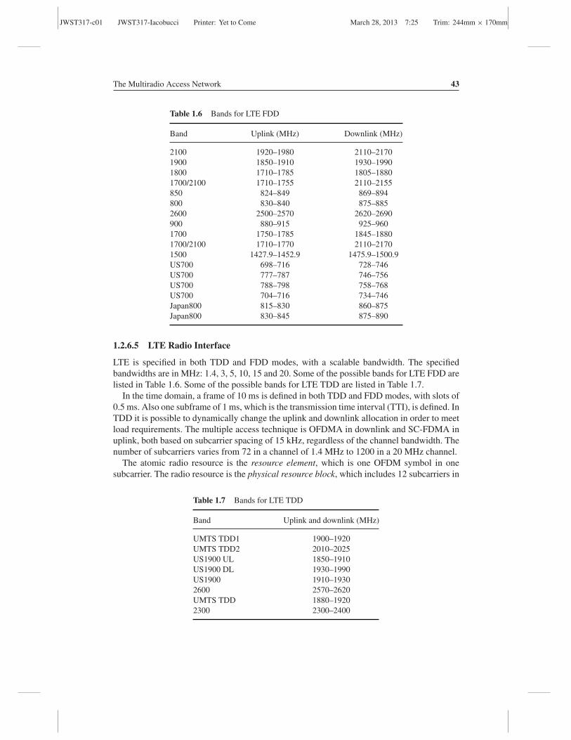
JWST317-c01 JWST317-Iacobucci Printer: Yet to Come March 28, 2013 7:25 Trim: 244mm × 170mm
The Multiradio Access Network 43
Table 1.6 Bands for LTE FDD
Band Uplink (MHz) Downlink (MHz)
2100 1920–1980 2110–21701900 1850–1910 1930–19901800 1710–1785 1805–18801700/2100 1710–1755 2110–2155850 824–849 869–894800 830–840 875–8852600 2500–2570 2620–2690900 880–915 925–9601700 1750–1785 1845–18801700/2100 1710–1770 2110–21701500 1427.9–1452.9 1475.9–1500.9US700 698–716 728–746US700 777–787 746–756US700 788–798 758–768US700 704–716 734–746Japan800 815–830 860–875Japan800 830–845 875–890
1.2.6.5 LTE Radio Interface
LTE is specified in both TDD and FDD modes, with a scalable bandwidth. The specifiedbandwidths are in MHz: 1.4, 3, 5, 10, 15 and 20. Some of the possible bands for LTE FDD arelisted in Table 1.6. Some of the possible bands for LTE TDD are listed in Table 1.7.
In the time domain, a frame of 10 ms is defined in both TDD and FDD modes, with slots of0.5 ms. Also one subframe of 1 ms, which is the transmission time interval (TTI), is defined. InTDD it is possible to dynamically change the uplink and downlink allocation in order to meetload requirements. The multiple access technique is OFDMA in downlink and SC-FDMA inuplink, both based on subcarrier spacing of 15 kHz, regardless of the channel bandwidth. Thenumber of subcarriers varies from 72 in a channel of 1.4 MHz to 1200 in a 20 MHz channel.
The atomic radio resource is the resource element, which is one OFDM symbol in onesubcarrier. The radio resource is the physical resource block, which includes 12 subcarriers in
Table 1.7 Bands for LTE TDD
Band Uplink and downlink (MHz)
UMTS TDD1 1900–1920UMTS TDD2 2010–2025US1900 UL 1850–1910US1900 DL 1930–1990US1900 1910–19302600 2570–2620UMTS TDD 1880–19202300 2300–2400
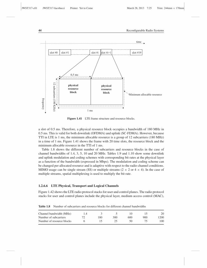
JWST317-c01 JWST317-Iacobucci Printer: Yet to Come March 28, 2013 7:25 Trim: 244mm × 170mm
44 Reconfigurable Radio Systems
slot #i slot #0 slot #1 slot #19
time
frequ
ency
slot #i+1
0,5 ms
12
sub
carriers (18
0 K
Hz)
physical resource
block
physical resource
block Minimum allocable resource
1 ms
Figure 1.41 LTE frame structure and resource blocks.
a slot of 0.5 ms. Therefore, a physical resource block occupies a bandwidth of 180 MHz in0.5 ms. This is valid for both downlink (OFDMA) and uplink (SC-FDMA). However, becauseTTI in LTE is 1 ms, the minimum allocable resource is a group of 12 subcarriers (180 MHz)in a time of 1 ms. Figure 1.41 shows the frame with 20 time slots, the resource block and theminimum allocable resource in the TTI of 1 ms.
Table 1.8 shows the different number of subcarriers and resource blocks in the case ofchannel bandwidths of 1.4, 3, 5, 10 and 20 MHz. Tables 1.9 and 1.10 show some downlinkand uplink modulation and coding schemes with corresponding bit rates at the physical layeras a function of the bandwidth (expressed in Mbps). The modulation and coding scheme canbe changed per allocated resource and is adaptive with respect to the radio channel conditions.MIMO usage can be single stream (SS) or multiple streams (2 × 2 or 4 × 4). In the case ofmultiple streams, spatial multiplexing is used to multiply the bit rate.
1.2.6.6 LTE Physical, Transport and Logical Channels
Figure 1.42 shows the LTE radio protocol stacks for user and control planes. The radio protocolstacks for user and control planes include the physical layer, medium access control (MAC),
Table 1.8 Number of subcarriers and resource blocks for different channel bandwidths
Channel bandwidth (MHz) 1.4 3 5 10 15 20Number of subcarriers 72 180 300 600 900 1200Number of resource blocks 6 15 25 50 75 100
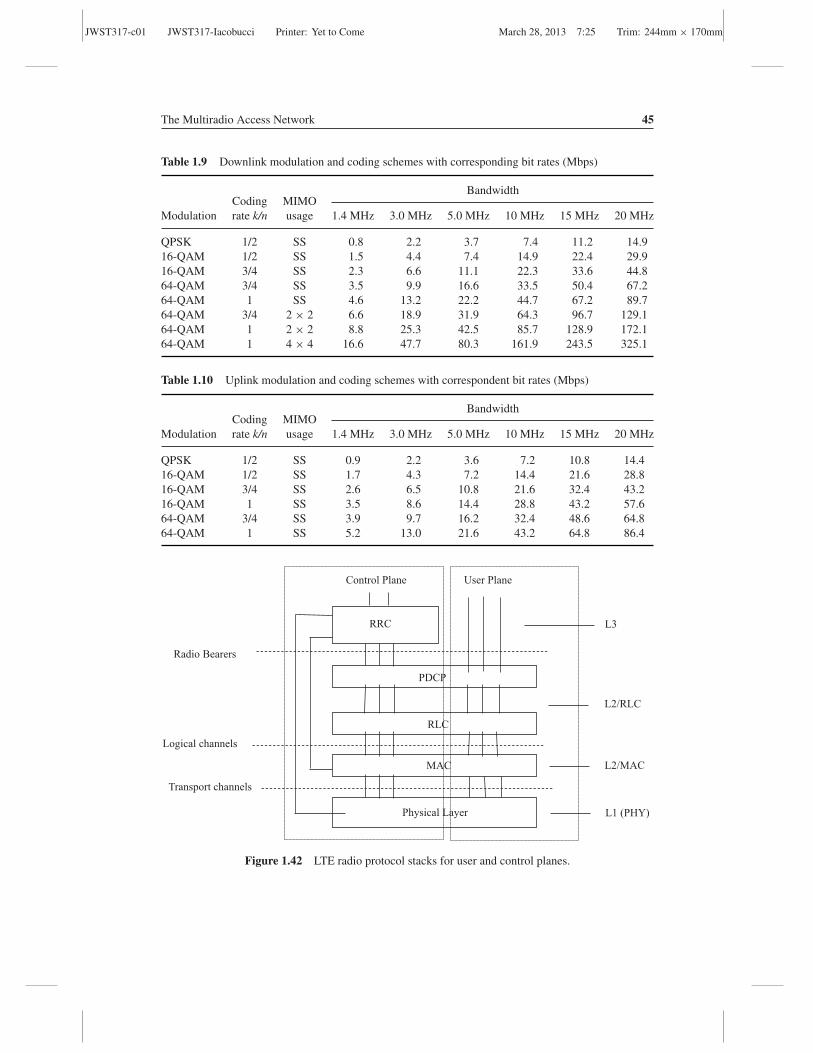
JWST317-c01 JWST317-Iacobucci Printer: Yet to Come March 28, 2013 7:25 Trim: 244mm × 170mm
The Multiradio Access Network 45
Table 1.9 Downlink modulation and coding schemes with corresponding bit rates (Mbps)
BandwidthCoding MIMO
Modulation rate k/n usage 1.4 MHz 3.0 MHz 5.0 MHz 10 MHz 15 MHz 20 MHz
QPSK 1/2 SS 0.8 2.2 3.7 7.4 11.2 14.916-QAM 1/2 SS 1.5 4.4 7.4 14.9 22.4 29.916-QAM 3/4 SS 2.3 6.6 11.1 22.3 33.6 44.864-QAM 3/4 SS 3.5 9.9 16.6 33.5 50.4 67.264-QAM 1 SS 4.6 13.2 22.2 44.7 67.2 89.764-QAM 3/4 2 × 2 6.6 18.9 31.9 64.3 96.7 129.164-QAM 1 2 × 2 8.8 25.3 42.5 85.7 128.9 172.164-QAM 1 4 × 4 16.6 47.7 80.3 161.9 243.5 325.1
Table 1.10 Uplink modulation and coding schemes with correspondent bit rates (Mbps)
BandwidthCoding MIMO
Modulation rate k/n usage 1.4 MHz 3.0 MHz 5.0 MHz 10 MHz 15 MHz 20 MHz
QPSK 1/2 SS 0.9 2.2 3.6 7.2 10.8 14.416-QAM 1/2 SS 1.7 4.3 7.2 14.4 21.6 28.816-QAM 3/4 SS 2.6 6.5 10.8 21.6 32.4 43.216-QAM 1 SS 3.5 8.6 14.4 28.8 43.2 57.664-QAM 3/4 SS 3.9 9.7 16.2 32.4 48.6 64.864-QAM 1 SS 5.2 13.0 21.6 43.2 64.8 86.4
MAC
RRC
Control Plane User Plane
Logical channels
Physical Layer L1 (PHY)
L2/RLC
L2/MAC
L3
Transport channels
RLC
PDCP
Radio Bearers
Figure 1.42 LTE radio protocol stacks for user and control planes.
JWST317-c01 JWST317-Iacobucci Printer: Yet to Come March 28, 2013 7:25 Trim: 244mm × 170mm
46 Reconfigurable Radio Systems
radio link control (RLC) and packet data convergence protocol (PDCP). Radio resource control(RRC) is on top of PDCP for the control plane. The physical layer is responsible for all theradio transmission functions.
MAC, RLC and PDCP are layer two protocols. MAC multiplexes packet data units (PDUs)from one or more logical channels into a transport channel. The RLC offers link control overthe radio interface for user and control data. PDCP provides services in the form of radiobearers to RRC for the control plane and to the IP layer for the user plane. Radio bearers areservices used to deliver C-plane and U-plane over the radio interface. RRC is responsible forlayer three signalling exchange between the mobile station and the evolved node B.
Logical channels, which are the resources offered from the MAC layer to the upper layers,are characterized by the nature of their information content; they carry information related toboth the user and control plane. Logical channels are:
• Broadcast control channel (BCCH): in downlink, broadcasts system information• Paging control channel (PCCH): in downlink, carries paging• Common control channel (CCCH): uplink and downlink, used to transmit Radio Resource
control (RRC) initial bidirectional signalling between the MS and eNB• Dedicated control channel (DCCH): uplink and downlink, used to transmit dedicated RRC
signalling between the MS and eNB• Dedicated traffic channel (DTCH): uplink and downlink, dedicated to user data transmission• Multicast control channel (MCCH): point-to-multipoint, downlink, for multicast control
information• Multicast traffic channel (MTCH): point-to-multipoint, downlink, for multicast traffic
Transport channels are resources offered from the physical to the MAC layer. Transportchannels in LTE are shared channels: there are no dedicated transport channels. Transportchannels are:
• Broadcast channel (BCH): in downlink, carries part of the system information (SI); additionalSI blocks are mapped in the DL-SCH.
• Paging channel (PCH): in downlink, carries paging information.• Downlink shared channel (DL-SCH): is the most important resource in downlink. Carries
data (DTCH) and signalling (BCCH, CCCH and DCCH). Can also carry multicast infor-mation. Supports hybrid automatic repeat request (HARQ), dynamic packet scheduling,adaptive modulation and coding.
• Multicast channel (MCH): downlink, carries multicast information.• Random access channel (RACH): uplink, carries control information between the MS and
eNB. Is subject to collisions.• Uplink shared channel (UL-SCH): is the most important resource in uplink. Carries data
(DTCH) and signalling (CCCH and DCCH). Supports HARQ, dynamic packet scheduling,adaptive modulation and coding.
Physical channels are the resources used for transmission over the radio interface. Physicalchannels are:
• Physical broadcast channel (PBCH): carries the master information block (MIB) from theBCH. In LTE, MIB contains very limited information, like the cell bandwidth, the physicalhybrid ARQ indicator channel (PHICH) structure, the system frame number (SFN).
JWST317-c01 JWST317-Iacobucci Printer: Yet to Come March 28, 2013 7:25 Trim: 244mm × 170mm
The Multiradio Access Network 47
• Physical HARQ indicator channel (PHICH): downlink, sends ACK/NACKs related to theuplink transmissions on the physical uplink shared channel (PUSCH). Each PHICH isaddressed to one MS.
• Physical downlink shared channel (PDSCH): is the most important downlink resource andcarries data and signalling. Is allocated on a TTI basis (1 ms) to the mobile stations. TheMAC scheduler assigns channel coding, modulation, subcarrier allocation and addresses DLtransmissions in the PDCCH.
• Physical downlink control channel (PDCCH): downlink, is used to assign resources in thePDSCH (downlink) and in the PUSCH/PUCCH (uplink).
• Physical control format indicator channel (PCFICH): downlink, indicates dimension, inOFDM symbols, of the control region used for PDCCH in the same subframe.
• Physical multicast channel (PMCH): downlink, is used for multicast.• Physical uplink shared channel (PUSCH): is the most important uplink resource in a cell
and carries data and signalling. Is allocated on a TTI basis (1 ms) to the mobile stations.The MAC scheduler assigns, per each MS, channel coding and modulation, and allocatesthe subcarriers.
• Physical uplink control channel (PUCCH): carries a channel quality indicator (CQI) andACK/NACK.
• Physical random access channel (PRACH): carries random access preambles during therandom access procedure.
Figure 1.43 shows downlink and uplink channels at logical, transport and physical layersand their mapping. In the figure are also shown the following signals:
• Primary synchronization signal (PSS) and secondary synchronization signal (SSS): both indownlink, are used for cell search and identification by the MS. Together they carry the cellidentifier (Id).
• Reference signals (RSs): used in uplink and downlink for channel estimation.
When an MS switches on, it searches and selects one cell through the synchronization signals,then derives system information from the PBCH, executes the random access procedure andsends signalling to register to the network and to set up the default bearer.
The assignment of downlink radio resources in the function of the radio conditions isperformed through the channel feedback reporting procedure. During the eNB transmission,the MS measures the downlink channel and sends a feedback to the eNB, which can includethe following parameters:
• Channel quality indicator (CQI): the MS indicates the transmission format (modulation andcoding scheme and transport block size, or TBS) that the mobile can receive in the next TTIwith a block error rate (BLER) lower than 10%.
• Rank indicator (RI): for MIMO, indicates the rank of the estimated channel matrix H. Equalsthe number of usable spatial streams. It is related to the whole system bandwidth.
• Precoding matrix indicator (PMI): indicates the preferred precoding matrix in a codebook.
Table 1.11 shows the considered parameters for uplink feedback. Based on the feedback,the eNB assigns downlink resources to the MS.
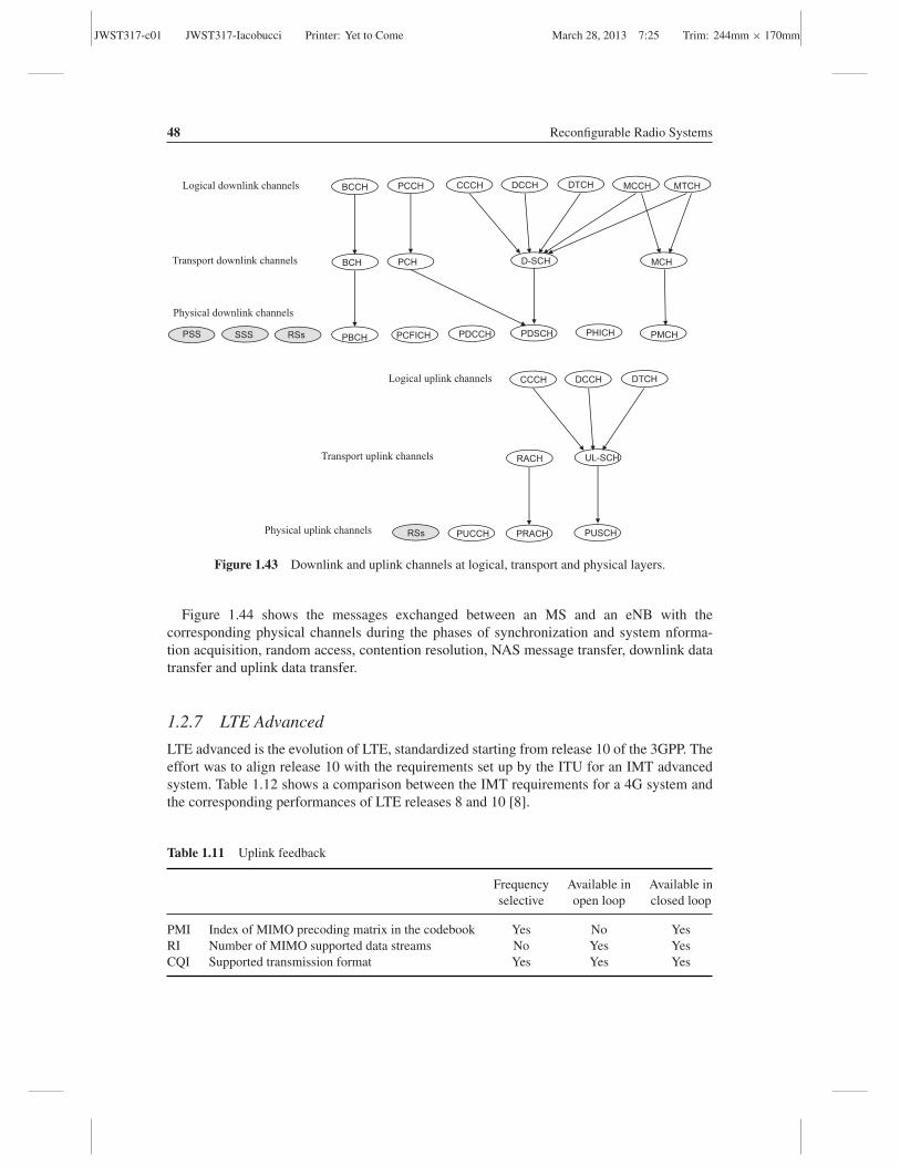
JWST317-c01 JWST317-Iacobucci Printer: Yet to Come March 28, 2013 7:25 Trim: 244mm × 170mm
48 Reconfigurable Radio Systems
Logical downlink channels
Transport downlink channels
Physical downlink channels
PCCH BCCH CCCH DCCH DTCH MCCH MTCH
PCH BCH D-SCH MCH
PDCCH PBCH PDSCH PMCH
Logical uplink channels
Transport uplink channels
Physical uplink channels
CCCH DCCH DTCH
RACH UL-SCH
PRACH PUSCH
RSs SSS PSS
RSs
PCFICH
PUCCH
PHICH
Figure 1.43 Downlink and uplink channels at logical, transport and physical layers.
Figure 1.44 shows the messages exchanged between an MS and an eNB with thecorresponding physical channels during the phases of synchronization and system nforma-tion acquisition, random access, contention resolution, NAS message transfer, downlink datatransfer and uplink data transfer.
1.2.7 LTE Advanced
LTE advanced is the evolution of LTE, standardized starting from release 10 of the 3GPP. Theeffort was to align release 10 with the requirements set up by the ITU for an IMT advancedsystem. Table 1.12 shows a comparison between the IMT requirements for a 4G system andthe corresponding performances of LTE releases 8 and 10 [8].
Table 1.11 Uplink feedback
Frequency Available in Available inselective open loop closed loop
PMI Index of MIMO precoding matrix in the codebook Yes No YesRI Number of MIMO supported data streams No Yes YesCQI Supported transmission format Yes Yes Yes

JWST317-c01 JWST317-Iacobucci Printer: Yet to Come March 28, 2013 7:25 Trim: 244mm × 170mm
The Multiradio Access Network 49
Synchronization Signals (SSs)
Master Information Block (PBCH)
System Information Block (PDSCH)
Random Access Preamble (PRACH)
DL assignment (PDCCH)
Random Access Response (PDSCH)
RRC Connection Request (PUSCH)
HARQ ACK (PHICH)
DL Assignment (PDCCH)
RRC Connection Setup (PDSCH)
HARQ ACK (PUCCH)
UL Grant (PDCCH)
RRC Connection Setup Complete (PUSCH)
HARQ ACK (PHICH)
DL assignment (PDCCH)
Data (PDSCH)
HARQ ACK & CQI (PUCCH)
Scheduling Request (PUCCH)
UL Grant (PDCCH)
Data (PUSCH)
HARQ ACK (PHICH)
MSe-NodeB
Synchronization
System Information acquisition
Random
Access
Contention
Resolution
NAS messageNon Access Stratum (NAS)
message transmission
DL Data Transfer
UL Data Transfer
Figure 1.44 Example of LTE radio transmission.
The principal radio features introduced in LTE advanced are:
• Carrier aggregation: two or more carriers, each with a bandwidth of up to 20 MHz, areaggregated. Contiguous and noncontiguous carriers can be aggregated, up to 100 MHz.
• Extended MIMO configurations: up to an 8 × 8 MIMO configuration is considered indownlink; up to a 4 × 4 MIMO configuration is considered in uplink.
Table 1.12 IMT requirements and LTE release 8 and 10 performances
IMT requirements LTE release 8 LTE release 10
Peak DL data rate 1 Gbps ∼ 325 Mbps > 1 GbpsPeak UL data rate 500 Mbps ∼ 85 Mbps > 500 MbpsControl plane latency 50 ms 50 ms 50 ms

JWST317-c01 JWST317-Iacobucci Printer: Yet to Come March 28, 2013 7:25 Trim: 244mm × 170mm
50 Reconfigurable Radio Systems
• Coordinated multiple point (CoMP) transmission and reception: this feature improves highdata rate coverage and cell-edge throughput. Downlink coordinated multipoint transmissionintroduces dynamic coordination among multiple geographically separated transmissionpoints.
• Relaying: used to improve the high data rates coverage and the cell-edge throughput, andto provide coverage in new areas. The relay node is wirelessly connected to a radio accessnetwork via a donor cell. There are two bidirectional radio links/interfaces: the access link,between the MS and the relay node (RN), and the backhaul link, between the RN andthe eNB. The relaying can be inband, if access and backhaul link use the same band, andoutband, if access and backhaul link use different bands.
1.3 Wireless Networks
Wireless networks are access networks with a radio connection between the mobile terminaland the first access network node. In general, they do not handle user mobility and thereforeare not radiomobile networks.
Wireless networks can be grouped as follows:
• Wireless personal area network (WPAN): are very short range networks, for low or highdata rate transmission.
• Wireless local area network (WLAN): are local area networks with a radio interface. Theirrange is of tens, or hundreds, of metres.
• Wireless metropolitan area network (WMAN): are networks with coverage of the order offew kilometres. They are used mainly for wireless local loop connectivity.
Figure 1.45 shows different coverage ranges of WPANs, WLANs and WMANs.Wireless networks are different for coverage range, supported bit rates, standards, etc. Figure
1.46 shows the principal IEEE standards for wireless networks.
1.3.1 Wireless LAN
A wireless local area network (WLAN) is a local area network with a wireless connectionbetween the user and the network. WLANs can be used for indoor areas (i.e., offices, homes,
WPAN
WLAN
WMAN
Figure 1.45 Coverage ranges of WPANs, WLANs and WMANs.
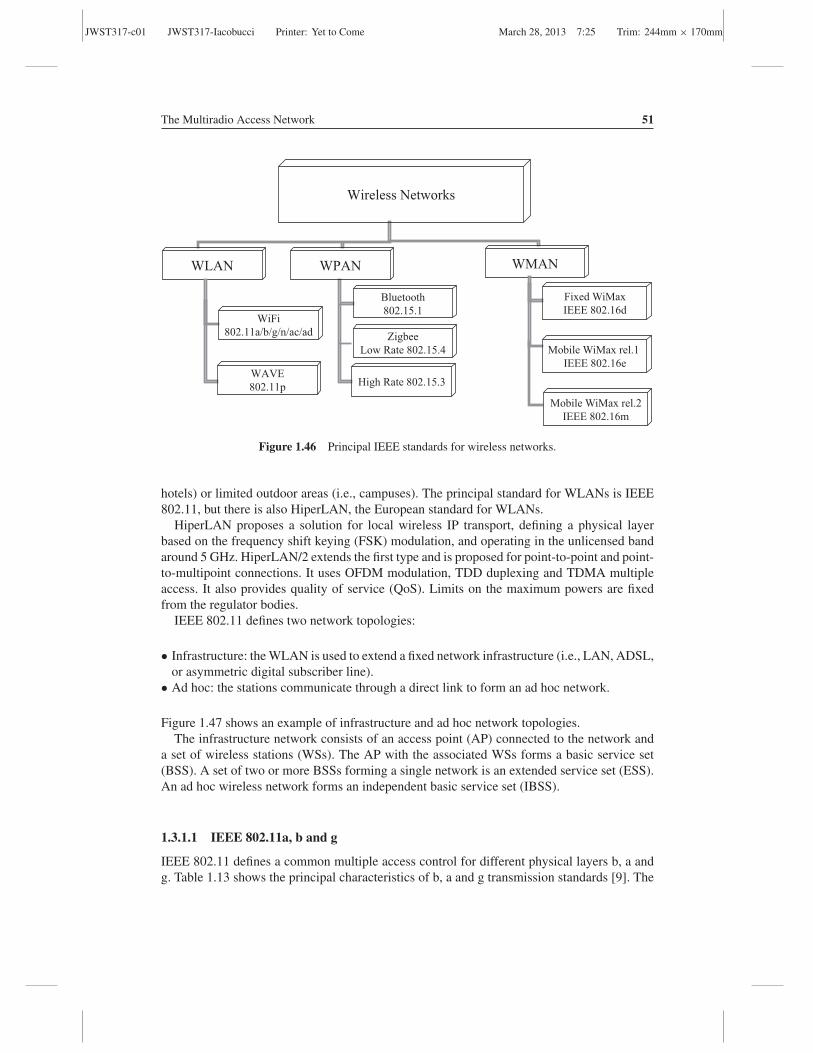
JWST317-c01 JWST317-Iacobucci Printer: Yet to Come March 28, 2013 7:25 Trim: 244mm × 170mm
The Multiradio Access Network 51
Wireless Networks
WLAN WPAN WMAN
WiFi
802.11a/b/g/n/ac/ad
Bluetooth
802.15.1
Zigbee
Low Rate 802.15.4
High Rate 802.15.3 WAVE
802.11p
Fixed WiMax
IEEE 802.16d
Mobile WiMax rel.1
IEEE 802.16e
Mobile WiMax rel.2
IEEE 802.16m
Figure 1.46 Principal IEEE standards for wireless networks.
hotels) or limited outdoor areas (i.e., campuses). The principal standard for WLANs is IEEE802.11, but there is also HiperLAN, the European standard for WLANs.
HiperLAN proposes a solution for local wireless IP transport, defining a physical layerbased on the frequency shift keying (FSK) modulation, and operating in the unlicensed bandaround 5 GHz. HiperLAN/2 extends the first type and is proposed for point-to-point and point-to-multipoint connections. It uses OFDM modulation, TDD duplexing and TDMA multipleaccess. It also provides quality of service (QoS). Limits on the maximum powers are fixedfrom the regulator bodies.
IEEE 802.11 defines two network topologies:
• Infrastructure: the WLAN is used to extend a fixed network infrastructure (i.e., LAN, ADSL,or asymmetric digital subscriber line).
• Ad hoc: the stations communicate through a direct link to form an ad hoc network.
Figure 1.47 shows an example of infrastructure and ad hoc network topologies.The infrastructure network consists of an access point (AP) connected to the network and
a set of wireless stations (WSs). The AP with the associated WSs forms a basic service set(BSS). A set of two or more BSSs forming a single network is an extended service set (ESS).An ad hoc wireless network forms an independent basic service set (IBSS).
1.3.1.1 IEEE 802.11a, b and g
IEEE 802.11 defines a common multiple access control for different physical layers b, a andg. Table 1.13 shows the principal characteristics of b, a and g transmission standards [9]. The
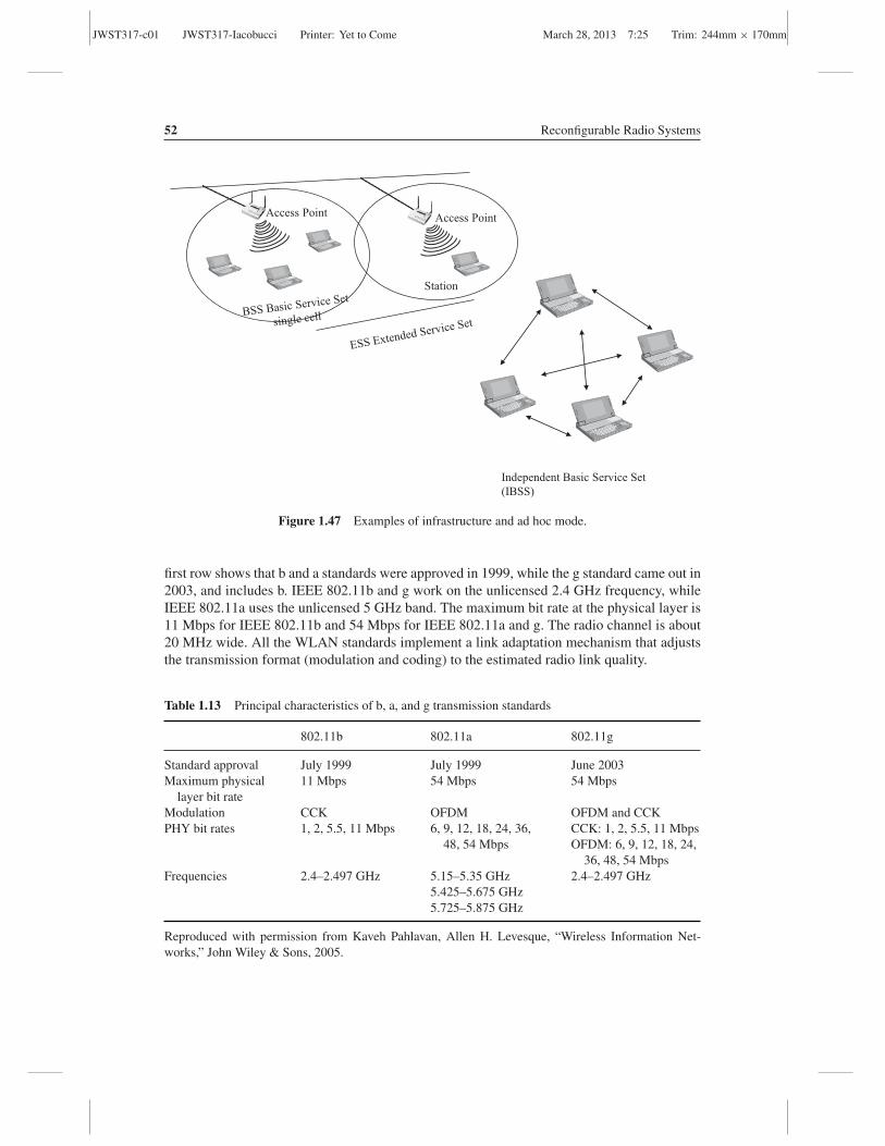
JWST317-c01 JWST317-Iacobucci Printer: Yet to Come March 28, 2013 7:25 Trim: 244mm × 170mm
52 Reconfigurable Radio Systems
Access Point
Station
Access Point
Independent Basic Service Set
(IBSS)
Figure 1.47 Examples of infrastructure and ad hoc mode.
first row shows that b and a standards were approved in 1999, while the g standard came out in2003, and includes b. IEEE 802.11b and g work on the unlicensed 2.4 GHz frequency, whileIEEE 802.11a uses the unlicensed 5 GHz band. The maximum bit rate at the physical layer is11 Mbps for IEEE 802.11b and 54 Mbps for IEEE 802.11a and g. The radio channel is about20 MHz wide. All the WLAN standards implement a link adaptation mechanism that adjuststhe transmission format (modulation and coding) to the estimated radio link quality.
Table 1.13 Principal characteristics of b, a, and g transmission standards
802.11b 802.11a 802.11g
Standard approval July 1999 July 1999 June 2003Maximum physical
layer bit rate11 Mbps 54 Mbps 54 Mbps
Modulation CCK OFDM OFDM and CCKPHY bit rates 1, 2, 5.5, 11 Mbps 6, 9, 12, 18, 24, 36,
48, 54 MbpsCCK: 1, 2, 5.5, 11 MbpsOFDM: 6, 9, 12, 18, 24,
36, 48, 54 MbpsFrequencies 2.4–2.497 GHz 5.15–5.35 GHz
5.425–5.675 GHz5.725–5.875 GHz
2.4–2.497 GHz
Reproduced with permission from Kaveh Pahlavan, Allen H. Levesque, “Wireless Information Net-works,” John Wiley & Sons, 2005.

JWST317-c01 JWST317-Iacobucci Printer: Yet to Come March 28, 2013 7:25 Trim: 244mm × 170mm
The Multiradio Access Network 53
Table 1.14 Low bit rates (1 and 2 Mbps)encoding for IEEE 802.11b
Bit rate Code length Modulation
1 Mbps 11 BPSK2 Mbps 11 QPSK
IEEE 802.11b uses the direct sequence spread spectrum (DSSS), with speeds of 1, 2, 5.5and 11 Mbps. Table 1.14 shows that 1 and 2 Mbps are obtained by changing the modulation(BPSK or QPSK) and by maintaining the binary Barker code for the spread spectrum. TheBarker code is the following spreading sequence of 11 chips: 1–111–1111–1–1–1.
Complementary code keying (CCK) is the encoding technique adopted for 5.5 and 11 Mbps,and the principle is shown in Figure 1.48. The CCK codeword is:
CCKcodeword = {e j(φ1+φ2+φ3+φ4), e j(φ1+φ3+φ4), e j(φ1+φ2·φ4),−e j(φ1+φ4), e j(φ1+φ2+φ3), e j(φ1+φ3),
−e j(φ1+φ2), e j(φ1)} (1.11)
Different bit-phase mapping is used for 5.5 and 11 Mbps bit rates. In the first case, fourbits are mapped into four phases to obtain the CCK codeword; in the second case, eight bitsare mapped into four phases to obtain the CCK codeword. The codeword identifies the QPSKmodulation symbols.
b0 b1 b2 b3 b4 b5 b6 b7bit phase mapping for
bit- phase mapping for
QPSKmodulator
bit- phase mapping for
CCK @ 11 Mbit/s
b0 b1 b2 b3 bit phase mapping for
CCK @ 5,5 Mbit/s
bi h i f CCK @ 5 5 Mbi /
bit-phase mapping for CCK @ 11 Mbit/s
Pairs of bits phase parameters
bit-phase mapping for CCK @ 5,5 Mbit/s
Pairs of bits phase parameters
(b0, b1) φ1
if b =0 φ π/2p p
(b0, b1) φ1
(b2, b3) φ2
(b4, b5) φ3
(b6, b7) φ4
if b2=0 φ2=π/2if b2=1 φ2=3π/2
∀ b2, b3 φ3=0
if b3=0 φ4=0
if b3=1 φ4=p(b6, b7) φ4 if b3=1 φ4 p
( ) ( ) ( ) ( ) ( ) ( ) ( ) ( ){ }12131321414214314321 ,,,,,,,φφφφφφφφφφφφφφφφφφφφ jjjjjjjj
codeword eeeeeeeeCCK +++++⋅++++++ −−=
Figure 1.48 High bit rates (5.5 and 11 Mbps) encoding for IEEE 802.11b.

JWST317-c01 JWST317-Iacobucci Printer: Yet to Come March 28, 2013 7:25 Trim: 244mm × 170mm
54 Reconfigurable Radio Systems
Table 1.15 IEEE 802.11a and IEEE 802.11g modulationand coding schemes
PHY bit rate (Mbps) Coding rate Modulation
6 1/2 BPSK9 3/4 BPSK
12 1/2 QPSK18 3/4 QPSK24 1/2 16-QAM36 3/4 16-QAM48 2/3 64-QAM54 3/4 64-QAM
The radio channels in IEEE 802.11 are about 20 MHz wide, and in general are not separatedbut overlapping. This results in a poorer radio link and then in a lower bit rate per user. IEEE802.11g and IEEE 802.11a introduce orthogonal frequency division multiplexing (OFDM),with transmission formats (modulation and coding) adapted to the radio link quality. Themodulation and coding schemes are the same for the two standards g and a, and are shown inTable 1.15.
1.3.1.2 IEEE 802.11 Medium Access Control
In the infrastructure mode, the wireless stations (WSs) must be synchronized to a commonclock, distributed from the access point (AP). The AP transmits, at target beacon transmission(TBTT) intervals, the beacon frame, where it copies the value of its timer (timestamp).Thestations of the BSS update their timer at that value. The other values broadcasted in the beaconframe are:
• Beacon interval;• Service set identifier (SSId); the AP can be configured not to transmit the SSId;• Supported rates;• Physical layer parameter set; and• Traffic information map: carries the identifiers of the WSs having data to be transmitted in
the next TBTT and is used for power save.
The MAC layer in IEEE 802.11 includes three functions: the distributed coordinationfunction (DCF), DCF-request to send/clear to send (DCF-RTS/CTS) and point coordinationfunction (PCF). The DCF is mandatory in IEEE 802.11. It uses carrier sense multiple access–collision avoidance (CSMA/CA). Before transmission, each WS listens to the medium; ifthe channel is sensed free for an established interval, called the distributed interframe space(DIFS), then the station transmits; otherwise it executes a backoff procedure, which calculatesa backoff time through a random function. The backoff time is calculated as follows:
Backoff time = Random() × slot time (1.12)

JWST317-c01 JWST317-Iacobucci Printer: Yet to Come March 28, 2013 7:25 Trim: 244mm × 170mm
The Multiradio Access Network 55
sourceMSDU
DIFS DIFSSIFS SIFS
destinationACK ACK
other transmitting
station
MSDU
slot time
backoff time
Figure 1.49 Example of CSMA/CA mechanism with two wireless stations.
Equation (1.11) assumes, according to a uniform distribution, values in the range [0, CW],where CW is the contention window. The slot time is an interval strictly dependent on thephysical layer (i.e., 20 μs for 802.11b and 9 μs for 802.11a). As soon as the wireless stationsenses the medium is free, it starts to decrease the backoff timer and freezes the countdown ifthe radio becomes busy. When the counter reaches the value zero, the WS, after having sensedthe medium free for a DIFS, transmits the MAC service data unit (MSDU). If the MSDU iscorrectly received, it is acknowledged through an ACK message. If the ACK is not receivedin a short interframe space (SIFS), the MSDU is retransmitted. The SIFS is shorter than theDIFS. Figure 1.49 shows an example of the CSMA/CA mechanism with two wireless stations.
An optional function provided from the IEEE 802.11 MAC is a distributed coordinationfunction-request to send/clear to send (DCF-RTS/CTS), also called a virtual carrier sense(VCS). The virtual carrier sense solves the ‘hidden node’ problem, shown in Figure 1.50.
Access PointA
B
sensing range of wireless station B
sensing range of wireless station A
access point radio coverage
Figure 1.50 Hidden node problem.

JWST317-c01 JWST317-Iacobucci Printer: Yet to Come March 28, 2013 7:25 Trim: 244mm × 170mm
56 Reconfigurable Radio Systems
In the figure, WSs A and B see the access point, but A is not able to see B and vice versa. Ais a hidden node for B and B is a hidden node for A. The mechanism of a two-way handshake,realized through the introduction of the packet’s request to send (RTS) and clear to send (CTS),solves the problem of hidden nodes. With virtual carrier sense wireless station A, following therules of DCF, transmits an RTS packet. The RTS contains the source address, the destinationaddress and the duration of the transmission expressed in μs. The access point acknowledgesthe reception of the RTS through a clear to send (CTS) packet, where it copies the durationfield of the received RTS, minus the value of an SIFS and of the time needed to transmit theCTS frame:
Duration Rx = Duration Tx − t(CTS) − SIFS
The CTS is received from all the stations in the AP range. After receiving the RTS orCTS packet, a station sets the network allocation vector (NAV) timer at the value ‘duration’contained in the received packet, and it will not attempt the access the medium until theNAV reaches the value zero. With virtual carrier sense collisions occur only among RTS/CTSpackets, which are very short.
The point coordination function (PCF) is optional in IEEE 802.11 and is provided only inthe infrastructure mode. In this case the access is controlled from the AP, acting as the pointcoordinator (PC). Contention free transmissions are allowed in a period called the contentionfree period (CFP). CFP begins with a beacon frame and alternates to the contention period(CP), where the access is regulated from the DCF. The alternation of CFP and CP is shown inFigure 1.51. A new time interval, the PCF interframe space (PIFS), which is smaller than theDIFS, is introduced to separate the end of the CP and the beacon transmission.
1.3.1.3 IEEE 802.11n
In 2009, IEEE 802.11n final standard version was approved. It introduces enhancements tothe MAC layer to decrease the latency and to the physical layer to improve the bit rate. Themain physical layer enhancements are:
• Dual carrier• MIMO
The maximum physical bit rate achievable in IEEE 802.11n is 600 Mbps using a 40 MHzwide channel and four spatial streams. Thirty-one modulation and coding schemes (MCSs)
Point
Coordinator
PIFS
B
CFP
DCF B DCFCFP
CP
PCF
CFP CP
CFP repetition interval
time
Figure 1.51 Alternation of DCF and PCF.
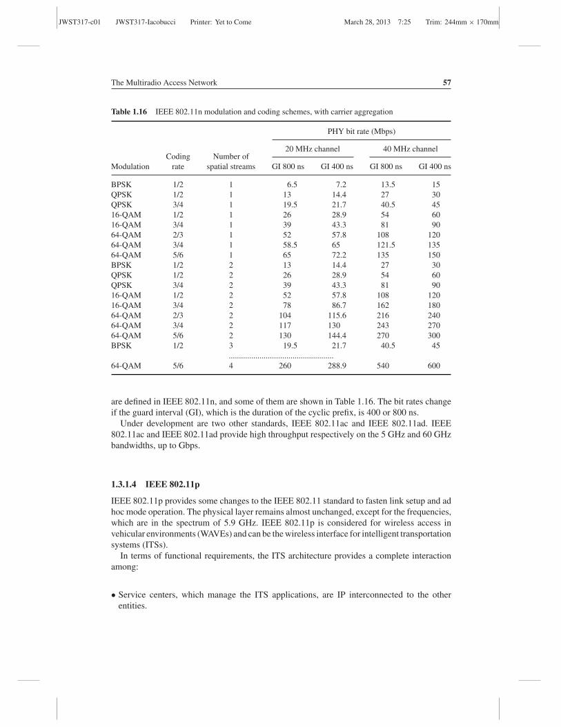
JWST317-c01 JWST317-Iacobucci Printer: Yet to Come March 28, 2013 7:25 Trim: 244mm × 170mm
The Multiradio Access Network 57
Table 1.16 IEEE 802.11n modulation and coding schemes, with carrier aggregation
PHY bit rate (Mbps)
20 MHz channel 40 MHz channelCoding Number of
Modulation rate spatial streams GI 800 ns GI 400 ns GI 800 ns GI 400 ns
BPSK 1/2 1 6.5 7.2 13.5 15QPSK 1/2 1 13 14.4 27 30QPSK 3/4 1 19.5 21.7 40.5 4516-QAM 1/2 1 26 28.9 54 6016-QAM 3/4 1 39 43.3 81 9064-QAM 2/3 1 52 57.8 108 12064-QAM 3/4 1 58.5 65 121.5 13564-QAM 5/6 1 65 72.2 135 150BPSK 1/2 2 13 14.4 27 30QPSK 1/2 2 26 28.9 54 60QPSK 3/4 2 39 43.3 81 9016-QAM 1/2 2 52 57.8 108 12016-QAM 3/4 2 78 86.7 162 18064-QAM 2/3 2 104 115.6 216 24064-QAM 3/4 2 117 130 243 27064-QAM 5/6 2 130 144.4 270 300BPSK 1/2 3 19.5 21.7 40.5 45
...................................................64-QAM 5/6 4 260 288.9 540 600
are defined in IEEE 802.11n, and some of them are shown in Table 1.16. The bit rates changeif the guard interval (GI), which is the duration of the cyclic prefix, is 400 or 800 ns.
Under development are two other standards, IEEE 802.11ac and IEEE 802.11ad. IEEE802.11ac and IEEE 802.11ad provide high throughput respectively on the 5 GHz and 60 GHzbandwidths, up to Gbps.
1.3.1.4 IEEE 802.11p
IEEE 802.11p provides some changes to the IEEE 802.11 standard to fasten link setup and adhoc mode operation. The physical layer remains almost unchanged, except for the frequencies,which are in the spectrum of 5.9 GHz. IEEE 802.11p is considered for wireless access invehicular environments (WAVEs) and can be the wireless interface for intelligent transportationsystems (ITSs).
In terms of functional requirements, the ITS architecture provides a complete interactionamong:
• Service centers, which manage the ITS applications, are IP interconnected to the otherentities.
JWST317-c01 JWST317-Iacobucci Printer: Yet to Come March 28, 2013 7:25 Trim: 244mm × 170mm
58 Reconfigurable Radio Systems
• Next generation roadside infrastructure, capable of interworking with the already deployedinfrastructure, is connected to the service centres and realizes the short–medium rangewireless communication with the vehicles.
• Vehicular infrastructure, capable of supporting communications with the other vehicles andwith roadside infrastructure.
• Personal devices used by the driver or the passenger to communicate with the ITS world.These elements are interconnected and exchange data and information through a set ofwireless communication networks.
1.3.2 Wireless MAN
A wireless metropolitan area network (WMAN) is a wireless network with a wide coverage,like a metropolitan area. The principal standard for WMANs is IEEE 802.16, which has twoversions:
• IEEE 802.16d, standardized in 2004 and called fixed WiMax.• IEEE 802.16e, which came out in 2005 as an amendment to the IEEE 802.16d. Even if IEEE
802.16e does not automatically imply mobility, it is often identified with mobile WiMax.
The term WiMAX is often used to identify IEEE 802.16 standard systems, but it comesfrom the WiMAX forum, an organization that certifies and promotes the compatibility andinteroperability of broadband wireless products based on IEEE Standard 802.16.
In many countries fixed WiMAX works around 3.5 GHz. General characteristics of fixedWiMAX are:
• Duplexing can be TTD or FDD.• The physical layer adopts OFDM modulation, with QPSK, 16-QAM, 64-QAM in uplink
and downlink.• The choice of the modulation and coding scheme is adapted to the radio channel conditions.• The bandwidth is variable, but with a fixed number of 256 subcarriers.• The MAC layer is connection oriented, based on TDMA in uplink and downlink. It supports
quality of service (QoS).
1.3.2.1 IEEE 802.16e
Mobile WiMAX [10] implies the idea of mobility. In that case, it must include procedures formobility handling and handover, and can be counted among the third generation systems.
The network architecture of mobile WiMAX is shown in Figure 1.52. It is an all IP networkarchitecture, with support of QoS. The mobile station (MS) connects, through a standardradio interface, with a mobile WiMax base station (BS). The BS realizes the radio coverage,broadcasts cell parameters, makes measurements over the uplink, receives the channel qualityindicators (CQIs) from the MSs and schedules radio resources to the mobile users. The basestations are connected through the R8 interface. The mobile WiMAX base stations are alsoconnected, through the R6 interface, to the access service network gateway (ASN-GW),which manages the user and control planes and connects the WiMAX access network to the

JWST317-c01 JWST317-Iacobucci Printer: Yet to Come March 28, 2013 7:25 Trim: 244mm × 170mm
The Multiradio Access Network 59
WiMAX
Base Station
WiMAX
Base Station
R8
ASN GWASN GW
R6R6
R4
signalling (C-plane)
data (U-plane)
IP based Network,
with QoS
MS
R3
R3
Figure 1.52 Mobile WiMAX network architecture.
IP-based core network. The ASN-GW is involved in the registration, mobility management,authentication, paging, billing and the service flow control.
General characteristics of the first IEEE 802.16e, also called mobile WiMAX release 1.0,are [11]:
• The duplexing is TDD.• The physical layer adopts OFDMA multiple access, with QPSK, 16-QAM and 64-QAM
modulations.• The choice of the modulation and coding scheme is adapted to the radio channel conditions.• The bandwidth is variable and can be 1.25, 5, 10 and 20 MHz.• Subcarrier spacing is independent from the bandwidth, and is of 10.94 kHz.• The MAC layer is connection oriented, based on the assignment of a group of subcarriers in
a given time. It supports quality of service (QoS). This is valid for both the uplink and thedownlink.
• Frequencies are licensed, in the range 3.4–3.6 GHz in most countries.• Possibility of MIMO.

JWST317-c01 JWST317-Iacobucci Printer: Yet to Come March 28, 2013 7:25 Trim: 244mm × 170mm
60 Reconfigurable Radio Systems
Table 1.17 Mobile WiMAX number of subcarriers for differentchannel bandwidths
System BW (MHz) 1.25 5 10 20Number of subcarriers 128 512 1024 2048
Because of the different characteristics, mobile WiMAX is not backward compatible withfixed WiMAX and has good performances even for fixed applications. Table 1.17 shows thedifferent number of subcarriers in the case of channel bandwidths (BWs) of 1.25, 5, 10 and20 MHz.
The performances of mobile WiMAX release 1.0 are comparable to the performances ofHSPA. In 2009, an evolution of mobile WiMAX came out, also known as mobile WiMAXrelease 1.5. It introduced an evolved radio interface with the following goals:
• Extension of the TDD profile to FDD paired bands;• Multicast/broadcast services enabling;• Improvement of MAC layer efficiency; and• New MIMO configurations, to improve capacity and cell edge throughput.
The performances of mobile WiMAX release 1.5 are comparable to the performances ofHSPA+.
1.3.2.2 IEEE 802.16m
In 2011 the IEEE 802.16m standard, also called mobile WiMAX release 2.0, was approved.IEEE 802.16m satisfies the International Telecommunication Union (ITU) requirements foran International Mobile Telecommunications (IMT)-advanced (4G) system. It can operate ina licensed spectrum allocated to mobile or fixed broadband services, such as:
• 450–470 MHz• 698–960 MHz, also identified for IEEE 802.16e• 1710–2025 MHz• 2110–2200 MHz• 2300–2400 MHz, also identified for IEEE 802.16e• 2500–2690 MHz, also identified for IEEE 802.16e• 3400–3600 MHz, also identified for IEEE 802.16e
IEEE 802.11m is backward compatible with IEEE 802.11e, and adds some features to meetIMT-advanced requirements, such as:
• Carrier aggregation: two or more carriers, each with a bandwidth up to 20 MHz, can beaggregated. Contiguous and noncontiguous carriers can be aggregated.
• Extended MIMO configurations: up to an 8 × 8 MIMO configuration is considered indownlink; up to a 4 × 4 MIMO configuration is considered in uplink.

JWST317-c01 JWST317-Iacobucci Printer: Yet to Come March 28, 2013 7:25 Trim: 244mm × 170mm
The Multiradio Access Network 61
• Multibase station MIMO: includes with downlink coordinated transmission among differentbase stations. Improves high data rate coverage and cell-edge throughput.
• Relaying: used to improve the coverage of high data rates, cell-edge throughput, providecoverage in new areas.
• Enhanced multicast and broadcast services (E-MBS): offered on multicast connections toimprove performance and operation in the power save mode.
1.3.3 Wireless PAN
A wireless personal area network (WPAN) is a wireless network with a very short coverage.There are many standards related to WPANs, with different properties like frequency, setuptime, bit rates, number of nodes, etc. This section lists the most commonly used WPANs, withtheir main characteristics.
1.3.3.1 Radio Frequency Identification
A radio frequency identification system consists of two elements:
• The transponder, or tag, placed on the item to be identified• The reader, or detector, able to read the tag
RFiD tags can be passive, if they are not alimented by a battery; active, if are alimented by abattery that is used to feed the radio communication part; semi-passive, if are equipped witha battery that feeds, for example, a memory or an onboard sensor but is not used for radiocommunication.
The coupling in passive RFiD can be:
• Inductive, based on the generation of a current induced by a magnetic field generated fromthe reader
• Backscatter, based on the transmission of an electromagnetic wave that is partially reflectedand eventually modulated (modulated backscatter)
Frequency ranges for RFiD systems can be of low, medium or high frequencies, as shownin Table 1.18. RFiD uses different frequencies, different standards and different typologiesof tags.
1.3.3.2 Near Field Communication
Near field communication (NFC) can be considered as an evolution of contactless RFiDtechnology. It can be integrated in a cell phone or in an SIM and can operate in three modes:
• As an emulation of a passive tag. In this case the cell phone can become a badge, a ticket, acredit card, etc.
• As a tag reader.• To make a peer-to-peer connection with another device in order to exchange data, etc.

JWST317-c01 JWST317-Iacobucci Printer: Yet to Come March 28, 2013 7:25 Trim: 244mm × 170mm
62 Reconfigurable Radio Systems
Table 1.18 Frequency ranges for RFiD, with standards and principal applications
Frequency Standards Application
125.5 kHz134.2 kHz
ISO 14223ISO 11785ISO11784ISO 18000-2
Animal identification
13.553–13.567 MHz ISO 18092ISO 14443ISO 15693ISO 18000-3
Contactless smartcards
433.05–434.79 MHz ISO 1800-7 Remote control
868–870 MHz (EU)902–928 MHz (USA)960 MHz (Japan)
ISO 18000-6 Logistic and object identification
2.4–2.483 GHz ISO 18000-4 Several systems, including vehicleidentification (ISO 1800-4)
NFC works at the frequency of 13.56 MHz, has a range of a few centimetres, is based on ISO18092 standard and is compatible with ISO 14443.
In March 2004 the NFC Forum was constituted, with the aim to ensure a minimum level ofinteroperability between devices and to develop specifications that are not included in the ISOstandard. NFC can be considered as a service enabler, mainly for e-payments and m-payments.
1.3.3.3 Bluetooth and IEEE 802.15.1
Bluetooth was born as an industrial standard working in the 2.4 GHz Industrial, Scientific andMedical (ISM) band, promoted by Ericsson and then developed by the Special Interest Group(SIG), an association constituted in 1999 from Sony Ericsson, IBM, Intel, Toshiba, Nokiaand other societies. The IEEE 802.15.1 standard was published in 2002 and is based on theBluetooth v1.1 specifications.
Bluetooth v1.1 divides the spectrum into 1 MHz sub-bands, and uses frequency hoppingas the multiple access technique. The modulation is Gaussian frequency shift keying. TheBluetooth range is of the order of magnitude of metres or tens of metres.
Bluetooth devices are able to create a network called a piconet. In the first phase, calledinquiry, a wireless station acting as a master searches for other devices that are in the directneighbourhood, called slaves. Then the page phase follows, where a slave device requests aconnection. The master assigns physical resources, like hopping frequency and ciphering keys.The physical bit rate shared among the devices in a piconet is 1 Mbps in the Bluetooth v1.1.Concatenated piconets form a scatternet. In Figure 1.53, three piconets form a scatternet.
After Bluetooth v1.1, other versions were standardized. Bluetooth v1.2 includes someenhancements to Bluetooth v1.1, like faster connection and discovery, improvements of voiceand audio quality. Bluetooth v2.1 is backward compatible with v1.2 and increases the maximumbit rate up to 3 Mbps. Bluetooth v.3 is for high bit rates, up to 24 Mbps. In this case theBluetooth link is used for connection establishment and a WiFi link is used for high bit ratedata transmission. Bluetooth v.4 is a protocol suite containing classic Bluetooth, Bluetooth

JWST317-c01 JWST317-Iacobucci Printer: Yet to Come March 28, 2013 7:25 Trim: 244mm × 170mm
The Multiradio Access Network 63
Master
Slave
Piconet 1
Piconet 2
Piconet 3
scatternet
Figure 1.53 Bluetooth piconets and scatternet.
high speed (based on WiFi) and Bluetooth low energy. Bluetooth low energy includes a newprotocol stack for low power consumption, low bit rate of about 250 kbps and short setup time.
Bluetooth low energy and near field communication (NFC) can both be integrated in mobilephones and can both be used as short range communication technologies.
1.3.3.4 IEEE 802.15.3
IEEE 802.15.3 is a standard, published in 2003, for high bit rate WPANs, which definesphysical and MAC protocols for a network supporting up to 245 wireless devices in an area oftens of metres, with bit rates ranging from 11 Mbps to 55 Mbps. IEEE 802.15.3 uses 15 MHzwide channels in the 2.4 GHz unlicensed band. The choice of modulation and trellis coderedundancy depends on the conditions of the radio channel.
The MAC protocol is based on a master–slave model in which a device, the piconet controller(PNC), controls the piconet. The PNC main tasks are:
• To manage device associations and disassociation,• To coordinate the access to the radio channel of the devices forming the piconet,• To coordinate the activities in the power save mode, and• To manage the coexistence with other piconets sharing the same radio channel.
The piconet can support different types of traffic, like audio and video streams or besteffort. The PNC sends a beacon that indicates the beginning of a superframe, consisting oftwo periods:
• Contention access period (CAP), based on CSMA and used for best effort traffic• Channel time allocation period (CTAP), used for streaming or real time services
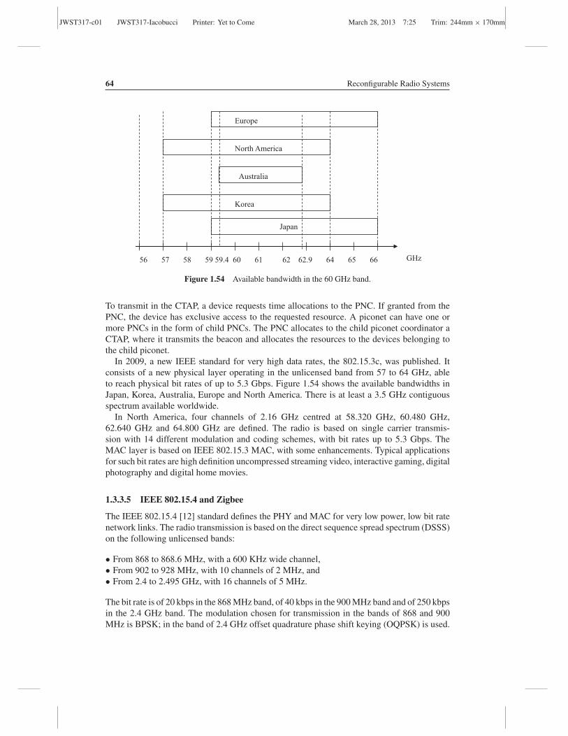
JWST317-c01 JWST317-Iacobucci Printer: Yet to Come March 28, 2013 7:25 Trim: 244mm × 170mm
64 Reconfigurable Radio Systems
GHz 56 57 58 59 59.4 60 61 62 62.9 64 65 66
Europe
North America
Australia
Korea
Japan
Figure 1.54 Available bandwidth in the 60 GHz band.
To transmit in the CTAP, a device requests time allocations to the PNC. If granted from thePNC, the device has exclusive access to the requested resource. A piconet can have one ormore PNCs in the form of child PNCs. The PNC allocates to the child piconet coordinator aCTAP, where it transmits the beacon and allocates the resources to the devices belonging tothe child piconet.
In 2009, a new IEEE standard for very high data rates, the 802.15.3c, was published. Itconsists of a new physical layer operating in the unlicensed band from 57 to 64 GHz, ableto reach physical bit rates of up to 5.3 Gbps. Figure 1.54 shows the available bandwidths inJapan, Korea, Australia, Europe and North America. There is at least a 3.5 GHz contiguousspectrum available worldwide.
In North America, four channels of 2.16 GHz centred at 58.320 GHz, 60.480 GHz,62.640 GHz and 64.800 GHz are defined. The radio is based on single carrier transmis-sion with 14 different modulation and coding schemes, with bit rates up to 5.3 Gbps. TheMAC layer is based on IEEE 802.15.3 MAC, with some enhancements. Typical applicationsfor such bit rates are high definition uncompressed streaming video, interactive gaming, digitalphotography and digital home movies.
1.3.3.5 IEEE 802.15.4 and Zigbee
The IEEE 802.15.4 [12] standard defines the PHY and MAC for very low power, low bit ratenetwork links. The radio transmission is based on the direct sequence spread spectrum (DSSS)on the following unlicensed bands:
• From 868 to 868.6 MHz, with a 600 KHz wide channel,• From 902 to 928 MHz, with 10 channels of 2 MHz, and• From 2.4 to 2.495 GHz, with 16 channels of 5 MHz.
The bit rate is of 20 kbps in the 868 MHz band, of 40 kbps in the 900 MHz band and of 250 kbpsin the 2.4 GHz band. The modulation chosen for transmission in the bands of 868 and 900MHz is BPSK; in the band of 2.4 GHz offset quadrature phase shift keying (OQPSK) is used.

JWST317-c01 JWST317-Iacobucci Printer: Yet to Come March 28, 2013 7:25 Trim: 244mm × 170mm
The Multiradio Access Network 65
The physical layer also defines procedures for:
• Activation and deactivation of the radio transceiver,• Energy detection (ED): to select the appropriate channel,• Link quality indication (LQI): to feedback the quality of a received packet, and• Clear channel assessment (CCA): to determine if the channel is available for transmission.
The MAC protocol is based on the optional use of a superframe structure. There is acoordinator that defines the superframe structure, starting from a beacon frame and composedof 16 slots. The beacon is sent from the coordinator for synchronization purposes and containsnetwork information and the superframe structure.
The superframe can be divided into two periods:
• Contention access period (CAP), based on CSMA• Contention free period (CFP), where the coordinator allocates time slots to the devices that
have requested guaranteed resources
The superframe can have inactive periods where devices turn to the power save mode. Ifthe coordinator does not want to enable the superframe, it does not send the beacon and alltransmissions follow CSMA/CA to access the channel.
Zigbee architecture is an enabler of sensor networks and Internet of things. A Zigbeenetwork is formed of devices that can be of two types: full function device (FFD) or reducedfunction device (RFD). The coordinator must be a full function device.
IEEE 802.15.4 MAC
Applications
IEEE 802.15.4
2400 MHz
PHY
IEEE 802.15.4
868/915 MHz
PHY
ZigBee
Figure 1.55 Zigbee protocol stack.

JWST317-c01 JWST317-Iacobucci Printer: Yet to Come March 28, 2013 7:25 Trim: 244mm × 170mm
66 Reconfigurable Radio Systems
ZigBee Coordinator
Star topology
Mesh topology
Point to point
Cluster three topology
ZigBee
Coordinators
Reduced Function Device
Full Function Device
Figure 1.56 Zigbee network architectures.
The Zigbee protocol stack is shown in Figure 1.55. It is based on IEEE 802.15.4 physicaland MAC layers and defines the upper layer protocols to create a multihop ad hoc network.The Zigbee layer includes the following features: form a network, enter and leave a network,routing, security, etc.
Zigbee network topology can be star, peer-to-peer and cluster three. Network topologies areshown in Figure 1.56. Cluster three topology is obtained by combining star, point-to-point andmesh topologies. Reduced function devices are limited to star topologies and are able to talkonly with the coordinator. Full function devices can be coordinators and can be used in anynetwork topology. A Zigbee network can be of up to 65 534 nodes; a coordinator can manageup to 255 active nodes at a time.
References
1. Mouly, M. and Pautet, M.-B. (1992) The GSM System for Mobile Communications, Telecom Publishing.2. Sanders, G., Thorens, L., Reisky, M. et al. (2003) GPRS Networks, John Wiley& Sons, Ltd, Chichester.3. Eylert, B. (2006) The Mobile Multimedia Business: Requirements and Solutions, Halsted Press.4. Kaaranen, H., Ahtiainen, A., Laitinen, L. et al. (2005) UMTS Networks: Architecture, Mobility and Services, 2nd
edition, John Wiley & Sons, Ltd, Chichester.5. A Regulatory Framework for UMTS, UMTS Forum Report 1, 1997.6. Holma, H. and Toskala, A. (2009) LTE for UMTS: OFDMA and SC-FDMA Based Radio Access, John Wiley &
Sons, Ltd, Chichester.7. Alamouti, S.M. (1998) A simple transmit diversity technique for wireless communications. IEEE Journal on
Selected Areas in Communications, 16 (8), October.

JWST317-c01 JWST317-Iacobucci Printer: Yet to Come March 28, 2013 7:25 Trim: 244mm × 170mm
The Multiradio Access Network 67
8. 3GPP TR 36.913 (2008) 3rd Generation Partnership Project; Technical Specification Group Radio Access Net-work; Requirements for Further Advancements for E-UTRA (LTE-Advanced), May 2008.
9. Pahlavan, K. and Levesque, A.H. (2005) Wireless Information Networks, John Wiley & Sons, Ltd, Chichester.10. Mobile WiMAX – Part I: A Technical Overview and Performance Evaluation, prepared on behalf of the WiMAX
Forum, 2006.11. Mobile WiMAX – Part II: A Comparative Analysis, prepared on behalf of the WiMAX Forum, 2006.12. Ergen, S.C. ZigBee/IEEE 802.15.4 Summary. http://www.eecs.berkeley.edu/csinem/academic/publications/
zigbee.pdf.

JWST317-c01 JWST317-Iacobucci Printer: Yet to Come March 28, 2013 7:25 Trim: 244mm × 170mm
68