Recent contributions of geotechnical centrifuge modelling to the understanding of jack-up spudcan...
15
Recent contributions of geotechnical centrifuge modelling to the understanding of jack-up spudcan behaviour Christophe Gaudin, Mark Jason Cassidy n , Britta Bienen, Muhammad Shazzad Hossain Centre for Offshore Foundation Systems, University of Western Australia, Perth, WA 6009, Australia article info Available online 17 January 2011 Keywords: Geotechnical engineering Offshore foundations Centrifuge modelling Spudcan Jack-up Soil–structure interaction abstract The paper presents an overview of the recent contributions of centrifuge modelling to the understanding of soil–structure interaction and the development of design and predictive methods in the field of mobile jack-up drilling rig foundations. Both advantages and limitations of the centrifuge methods are detailed and key examples are presented. The benefits provided by centrifuge modelling to the development of analysis methods that are now being used within the jack-up industry are highlighted. To conclude, industry trends and research opportunities are discussed, as is the possible role of the geotechnical centrifuge in finding solutions to these new needs. & 2010 Elsevier Ltd. All rights reserved. 1. Introduction In the offshore oil and gas industry, most drilling operations in water depths up to around 120 m are performed from self-elevat- ing mobile jack-up units. These offshore platforms typically have a buoyant triangular hull, three independent truss-work legs and foundations, commonly known as ‘spudcans’, that approximate large inverted cones. For jack-up installation and removal from site, a rack and pinion system are used to jack the legs up and down through the deck (Fig. 1). Roughly circular in plan, spudcans typically have a shallow conical underside (in the order of 15–301 to the horizontal), some with a sharp protruding spigot. In the larger jack-ups in use today, the spudcans can be in excess of 20 m in diameter, with shapes varying with manufacturer and rig. As an alternative, some jack-ups use a mat support that connects all of the legs together. These have applicability in very soft sediments, because of the increased bearing area of the mat. Jack-up leg lengths are in the order of 100–205 m. Jack-up rigs are self-installing. They are towed to site with their legs elevated out of the water. On location, their legs are lowered to rest on the seabed. Once the jack-up has been positioned, the spudcans are jacked until an adequate bearing capacity exists for the hull to be lifted clear of the water. The spudcan foundations are then preloaded by pumping sea-water into the ballast tanks in the hull. This ‘proof tests’ the foundations by exposing them to a larger vertical load than the spudcan’s proportion of the rig’s self-weight (usually by a factor of 1.3–2). The ballast tanks are emptied before drilling operations begin. During the preloading process, challenges faced by the geotech- nical engineer include an accurate prediction of the penetration depth and ensuring the stability of the jack-up during penetration. Instabil- ities can occur due to eccentric loading of the spudcans by a slope or an existing footprint on the seabed, or by a rapid leg penetration during a ‘punch-through’ failure. In the latter, the spudcan temporarily loses vertical capacity as it punches through a layer of stronger soil into underlaying softer conditions. After the jack-up has been installed, it typically operates at the site for as little as days or as long as a number of years. Engineers must assess the jack-up stability during this operational phase prior to rig installation, with the major issue being capacity under storm loading. During a storm, environmental wind, wave and current forces impose horizontal, moments and even torsional loads on the spudcans, as well as altering the vertical load sharing between the spudcans. Geotechnical engineers must be able to describe the behaviour of spudcan footings to these combined loads. When the jack-up is to be finally moved from the site, the spudcan footings must be removed from the ground. Deep pene- trations can make this operation difficult, with the time to pull the spudcans clear being reported to exceed one month in extreme circumstances. There is an industry need for better understanding of the extraction mechanisms and the development of a more efficient extraction procedure. Before a jack-up can operate at a given location, a site-specific assessment of its installation, operation and extraction must be performed. This on-going assessment is what differentiates the jack-up analysis from that of the conventional fixed platforms and most onshore operations. The ‘‘Guidelines for the Site Specific Assessment of Mobile Jack-Up Units’’ as published by Society of Naval Architects and Marine Engineers (SNAME) has been the accepted as an industry standard (SNAME, 1994, 2008), though Contents lists available at ScienceDirect journal homepage: www.elsevier.com/locate/oceaneng Ocean Engineering 0029-8018/$ - see front matter & 2010 Elsevier Ltd. All rights reserved. doi:10.1016/j.oceaneng.2010.12.001 n Corresponding author. Tel.: + 61 8 6488 3732; fax: + 61 8 6488 1044. E-mail addresses: [email protected] (C. Gaudin), [email protected] (M.J. Cassidy), [email protected] (B. Bienen), [email protected] (M.S. Hossain). Ocean Engineering 38 (2011) 900–914
-
Upload
independent -
Category
Documents
-
view
0 -
download
0
Transcript of Recent contributions of geotechnical centrifuge modelling to the understanding of jack-up spudcan...
Ocean Engineering 38 (2011) 900–914
Contents lists available at ScienceDirect
Ocean Engineering
0029-80
doi:10.1
n Corr
E-m
mark.ca
hossain
journal homepage: www.elsevier.com/locate/oceaneng
Recent contributions of geotechnical centrifuge modelling to theunderstanding of jack-up spudcan behaviour
Christophe Gaudin, Mark Jason Cassidy n, Britta Bienen, Muhammad Shazzad Hossain
Centre for Offshore Foundation Systems, University of Western Australia, Perth, WA 6009, Australia
a r t i c l e i n f o
Available online 17 January 2011
Keywords:
Geotechnical engineering
Offshore foundations
Centrifuge modelling
Spudcan
Jack-up
Soil–structure interaction
18/$ - see front matter & 2010 Elsevier Ltd. A
016/j.oceaneng.2010.12.001
esponding author. Tel.: +61 8 6488 3732; fax
ail addresses: [email protected] (C. Ga
[email protected] (M.J. Cassidy), britta.biene
@civil.uwa.edu.au (M.S. Hossain).
a b s t r a c t
The paper presents an overview of the recent contributions of centrifuge modelling to the understanding
of soil–structure interaction and the development of design and predictive methods in the field of mobile
jack-up drilling rig foundations. Both advantages and limitations of the centrifuge methods are detailed
and key examples are presented. The benefits provided by centrifuge modelling to the development of
analysis methods that are now being used within the jack-up industry are highlighted. To conclude,
industry trends and research opportunities are discussed, as is the possible role of the geotechnical
centrifuge in finding solutions to these new needs.
& 2010 Elsevier Ltd. All rights reserved.
1. Introduction
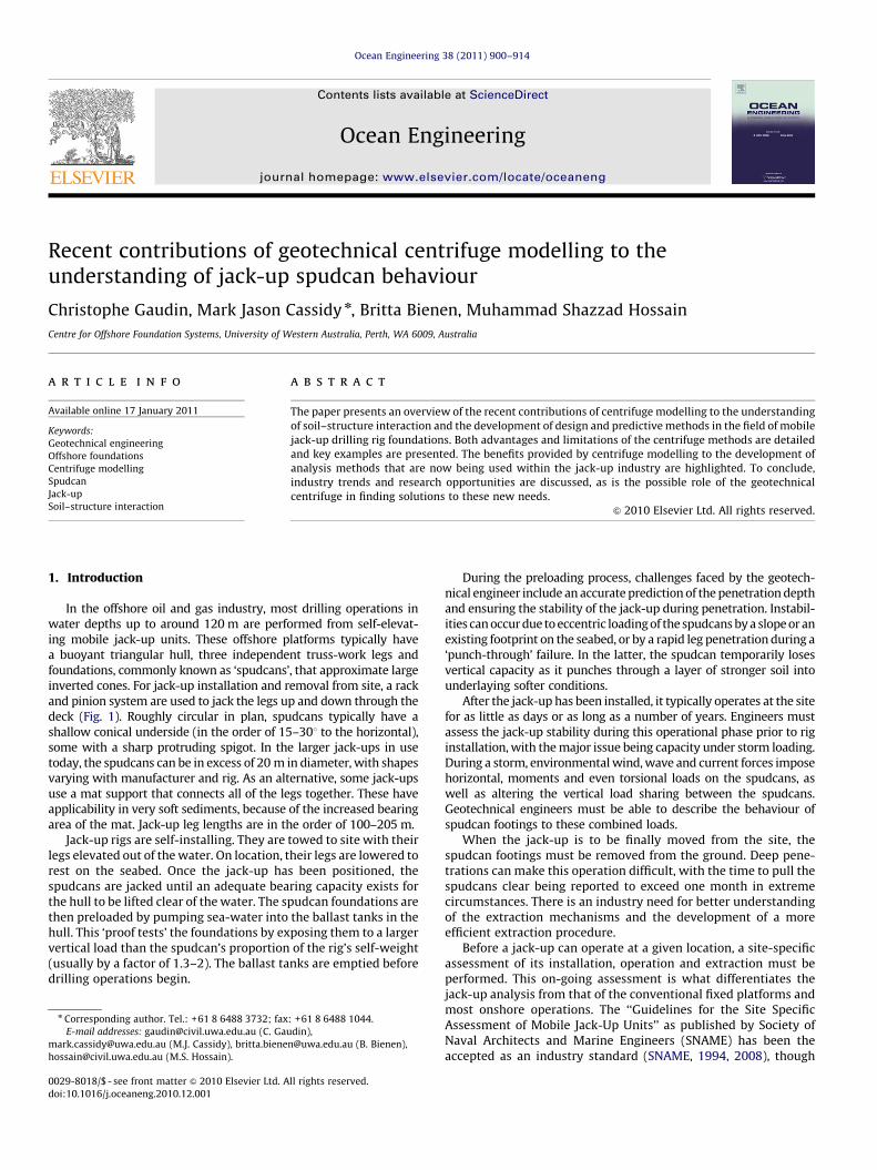
In the offshore oil and gas industry, most drilling operations inwater depths up to around 120 m are performed from self-elevat-ing mobile jack-up units. These offshore platforms typically havea buoyant triangular hull, three independent truss-work legs andfoundations, commonly known as ‘spudcans’, that approximate largeinverted cones. For jack-up installation and removal from site, a rackand pinion system are used to jack the legs up and down through thedeck (Fig. 1). Roughly circular in plan, spudcans typically have ashallow conical underside (in the order of 15–301 to the horizontal),some with a sharp protruding spigot. In the larger jack-ups in usetoday, the spudcans can be in excess of 20 m in diameter, with shapesvarying with manufacturer and rig. As an alternative, some jack-upsuse a mat support that connects all of the legs together. These haveapplicability in very soft sediments, because of the increased bearingarea of the mat. Jack-up leg lengths are in the order of 100–205 m.
Jack-up rigs are self-installing. They are towed to site with theirlegs elevated out of the water. On location, their legs are lowered torest on the seabed. Once the jack-up has been positioned, thespudcans are jacked until an adequate bearing capacity exists forthe hull to be lifted clear of the water. The spudcan foundations arethen preloaded by pumping sea-water into the ballast tanks in thehull. This ‘proof tests’ the foundations by exposing them to a largervertical load than the spudcan’s proportion of the rig’s self-weight(usually by a factor of 1.3–2). The ballast tanks are emptied beforedrilling operations begin.
ll rights reserved.
: +61 8 6488 1044.
udin),
[email protected] (B. Bienen),
During the preloading process, challenges faced by the geotech-nical engineer include an accurate prediction of the penetration depthand ensuring the stability of the jack-up during penetration. Instabil-ities can occur due to eccentric loading of the spudcans by a slope or anexisting footprint on the seabed, or by a rapid leg penetration during a‘punch-through’ failure. In the latter, the spudcan temporarily losesvertical capacity as it punches through a layer of stronger soil intounderlaying softer conditions.
After the jack-up has been installed, it typically operates at the sitefor as little as days or as long as a number of years. Engineers mustassess the jack-up stability during this operational phase prior to riginstallation, with the major issue being capacity under storm loading.During a storm, environmental wind, wave and current forces imposehorizontal, moments and even torsional loads on the spudcans, aswell as altering the vertical load sharing between the spudcans.Geotechnical engineers must be able to describe the behaviour ofspudcan footings to these combined loads.
When the jack-up is to be finally moved from the site, thespudcan footings must be removed from the ground. Deep pene-trations can make this operation difficult, with the time to pull thespudcans clear being reported to exceed one month in extremecircumstances. There is an industry need for better understandingof the extraction mechanisms and the development of a moreefficient extraction procedure.
Before a jack-up can operate at a given location, a site-specificassessment of its installation, operation and extraction must beperformed. This on-going assessment is what differentiates thejack-up analysis from that of the conventional fixed platforms andmost onshore operations. The ‘‘Guidelines for the Site SpecificAssessment of Mobile Jack-Up Units’’ as published by Society ofNaval Architects and Marine Engineers (SNAME) has been theaccepted as an industry standard (SNAME, 1994, 2008), though
Fig. 1. Example of jack-up unit and spudcan foundation (after Le Tirant, 1979).
C. Gaudin et al. / Ocean Engineering 38 (2011) 900–914 901
more recently an International Standard Organisation (ISO) docu-ment has been drafted (ISO, 2009). These documents have beensignificantly enhanced by analysis methods developed throughcentrifuge testing, with example details provided in this paper.
The more recent InSafeJIP is updating industry guidelines for theinstallation and removal of jack-ups (Osborne et al., 2008, 2009). Akey task of the InSafeJIP is to verify analytical models developedagainst offshore in-situ field records. This includes methodsdeveloped through centrifuge experiments initially at Cambridgeand Manchester Universities, but more recently at the University ofWestern Australia and the National University of Singapore.
1.1. Aims of the paper
Centrifuge modelling is now a well established modelling techni-que within the geotechnical community and has been used for decadesto provide insights into soil behaviour and soil–structure interaction.The benefits of the centrifuge to model jack-up foundations wereaddressed in some detail when Martin (2001) presented a state-of-the-art report on the impact of centrifuge modelling in offshore geotech-nics. Since this review in 2001, experimental testing in the geotechnicalcentrifuge has contributed to new insights, predictive methods anddesign guidelines in all three areas of installation, operation andextraction. A selection of examples is presented in this paper.
After an introduction to the principles, advantages and limita-tions of centrifuge modelling, the examples are presented. Thesefurther develop the issues highlighted in this introduction, discusscentrifuge technologies, present research outcomes and highlightapplications within the jack-up industry. All of these themes arealso summarised in Table 1. The example contributions provided
are organised following the three distinct phases of jack-upoperations: installation of the jack-up, capacity under stormloading during operation and removal of the jack-up.
Due to the space limitations of a journal paper, some of thesignificant contributions of the centrifuge made prior to 2001 andsome that pertain to particular issues are not covered. Notably, thisincludes a thorough coverage of the research establishing spudcanyield surface approaches on the Cambridge centrifuge (see Deanet al., 1993, Wong et al., 1993 amongst others), the bearing capacity ofspudcans in silica and calcareous sands (e.g. Finnie and Randolph,1994; Dean et al., 1993; Teh et al., 2006; White et al., 2008), the inter-action between a spudcan during installation and the nearby piles of afixed jacket platform (e.g. Siciliano et al., 1990; Leung et al., 2006,2008; Xie et al., 2006, 2010) and the contributions of Ng and Lee(2002) to predicting spudcan settlements under cyclic loading. Otherissues, such as predicting the dynamic motion of jack-ups, spudcanscour and creep settlements, are also important to the design andsite-specific assessment of jack-ups, but are beyond the scope ofthis paper.
2. Centrifuge modelling
2.1. Principles of centrifuge modelling
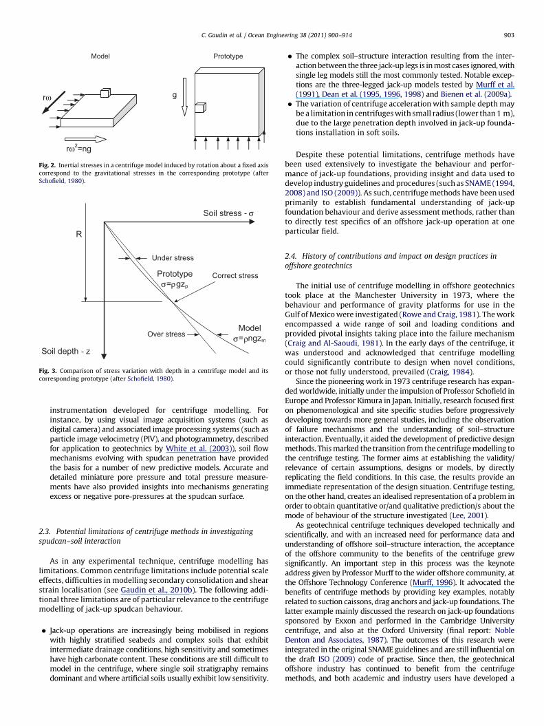
The constitutive behaviour of soil is highly non-linear and stresslevel dependent. To simulate accurately in a physical model(commonly called model), the behaviour of a full scale geotechnicalstructure (commonly called prototype) and the in-situ stressesmust be reproduced in the model. This is achieved by subjecting themodel to a centrifuge acceleration; increasing the self-weight of thesoil by the ratio of the centrifuge acceleration to the Earth’s gravity(see Fig. 2). This ratio, denoted n, is the multiplicative scaling factorrequired to convert dimensions in a centrifuge model to the dimen-sions of the corresponding field scale situation. Hence, stresses s inthe prototype at a depth zp, expressed ass¼rgzp, are equivalent to thestresses in the model at a depth zm¼zp/n, which are expressed ass¼rngzm. Because the inertia acceleration field is given by o2R
(where R is the radius of the centrifuge acceleration ando the angularrotational velocity), the variation of stress with depth in the modelvaries slightly compared to the linear variation with depth in theprototype (see Fig. 3). However, this is accounted for in the inter-pretation of centrifuge modelling results. General descriptions ofcentrifuge modelling are provided by Schofield (1980), Taylor (1995)and Muir Wood (2004). Similitude principles and scaling lawsrequired to extrapolate model dimensions to prototype dimensionsare developed in Garnier et al. (2007).
2.2. Advantages of centrifuge methods in investigating spudcan–soil
interaction
Centrifuge methods offer the following benefits that are rele-vant to jack-up unit spudcan foundations:
�
Correct simulation of soil effective stress and soil stiffness: this isrequired to realistically simulate soil stress–strain behaviouraround the spudcan. � Shortened time frames: the centrifuge requires a relatively smallvolume of soil, limiting the time required for sample preparation.For soft soil, the primary consolidation may be further shortenedby self-weight consolidation under the gravitational acceleration.Similarly, testing sequences are considerably shortened thoughstill ensuring the correct drainage conditions. This allows data tobe collected in a short time frame and at cost orders of magnitudelower than those associated with field testing. Typically, a series ofsix to ten tests in the centrifuge can be undertaken within
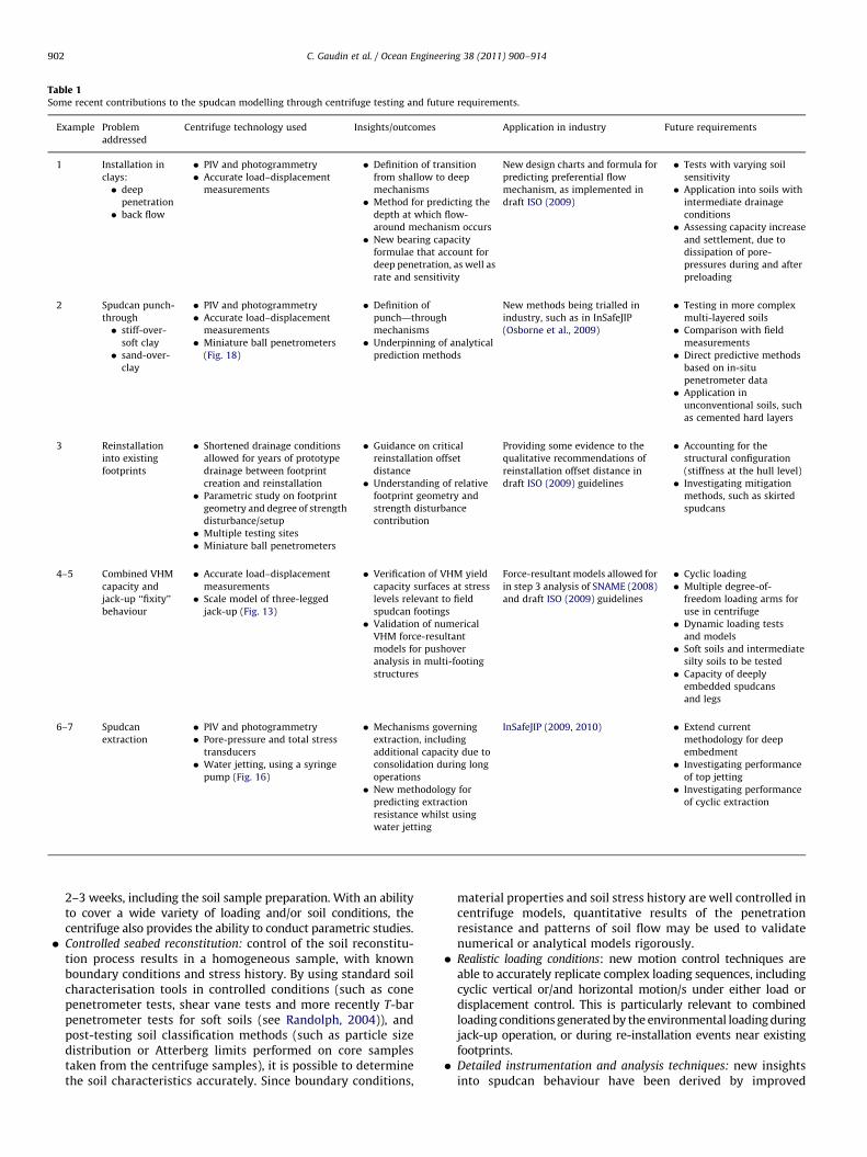
Table 1Some recent contributions to the spudcan modelling through centrifuge testing and future requirements.
Example Problem
addressed
Centrifuge technology used Insights/outcomes Application in industry Future requirements
1 Installation in
clays:
� deep
penetration
� back flow
� PIV and photogrammetry
� Accurate load–displacement
measurements
� Definition of transition
from shallow to deep
mechanisms
� Method for predicting the
depth at which flow-
around mechanism occurs
� New bearing capacity
formulae that account for
deep penetration, as well as
rate and sensitivity
New design charts and formula for
predicting preferential flow
mechanism, as implemented in
draft ISO (2009)
� Tests with varying soil
sensitivity
� Application into soils with
intermediate drainage
conditions
� Assessing capacity increase
and settlement, due to
dissipation of pore-
pressures during and after
preloading
2 Spudcan punch-
through
� stiff-over-
soft clay
� sand-over-
clay
� PIV and photogrammetry
� Accurate load–displacement
measurements
� Miniature ball penetrometers
(Fig. 18)
� Definition of
punch—through
mechanisms
� Underpinning of analytical
prediction methods
New methods being trialled in
industry, such as in InSafeJIP
(Osborne et al., 2009)
� Testing in more complex
multi-layered soils
� Comparison with field
measurements
� Direct predictive methods
based on in-situ
penetrometer data
� Application in
unconventional soils, such
as cemented hard layers
3 Reinstallation
into existing
footprints
� Shortened drainage conditions
allowed for years of prototype
drainage between footprint
creation and reinstallation
� Parametric study on footprint
geometry and degree of strength
disturbance/setup
� Multiple testing sites
� Miniature ball penetrometers
� Guidance on critical
reinstallation offset
distance
� Understanding of relative
footprint geometry and
strength disturbance
contribution
Providing some evidence to the
qualitative recommendations of
reinstallation offset distance in
draft ISO (2009) guidelines
� Accounting for the
structural configuration
(stiffness at the hull level)
� Investigating mitigation
methods, such as skirted
spudcans
4–5 Combined VHM
capacity and
jack-up ‘‘fixity’’
behaviour
� Accurate load–displacement
measurements
� Scale model of three-legged
jack-up (Fig. 13)
� Verification of VHM yield
capacity surfaces at stress
levels relevant to field
spudcan footings
� Validation of numerical
VHM force-resultant
models for pushover
analysis in multi-footing
structures
Force-resultant models allowed for
in step 3 analysis of SNAME (2008)
and draft ISO (2009) guidelines
� Cyclic loading
� Multiple degree-of-
freedom loading arms for
use in centrifuge
� Dynamic loading tests
and models
� Soft soils and intermediate
silty soils to be tested
� Capacity of deeply
embedded spudcans
and legs
6–7 Spudcan
extraction
� PIV and photogrammetry
� Pore-pressure and total stress
transducers
� Water jetting, using a syringe
pump (Fig. 16)
� Mechanisms governing
extraction, including
additional capacity due to
consolidation during long
operations
� New methodology for
predicting extraction
resistance whilst using
water jetting
InSafeJIP (2009, 2010) � Extend current
methodology for deep
embedment
� Investigating performance
of top jetting
� Investigating performance
of cyclic extraction
C. Gaudin et al. / Ocean Engineering 38 (2011) 900–914902
2–3 weeks, including the soil sample preparation. With an abilityto cover a wide variety of loading and/or soil conditions, thecentrifuge also provides the ability to conduct parametric studies.
� Controlled seabed reconstitution: control of the soil reconstitu-tion process results in a homogeneous sample, with knownboundary conditions and stress history. By using standard soilcharacterisation tools in controlled conditions (such as conepenetrometer tests, shear vane tests and more recently T-barpenetrometer tests for soft soils (see Randolph, 2004)), andpost-testing soil classification methods (such as particle sizedistribution or Atterberg limits performed on core samplestaken from the centrifuge samples), it is possible to determinethe soil characteristics accurately. Since boundary conditions,
material properties and soil stress history are well controlled incentrifuge models, quantitative results of the penetrationresistance and patterns of soil flow may be used to validatenumerical or analytical models rigorously.
� Realistic loading conditions: new motion control techniques areable to accurately replicate complex loading sequences, includingcyclic vertical or/and horizontal motion/s under either load ordisplacement control. This is particularly relevant to combinedloading conditions generated by the environmental loading duringjack-up operation, or during re-installation events near existingfootprints.
� Detailed instrumentation and analysis techniques: new insightsinto spudcan behaviour have been derived by improved
Prototype
g
Model
rω2=ng
rω
Fig. 2. Inertial stresses in a centrifuge model induced by rotation about a fixed axis
correspond to the gravitational stresses in the corresponding prototype (after
Schofield, 1980).
σ
σ ρ
σ ρ
Fig. 3. Comparison of stress variation with depth in a centrifuge model and its
corresponding prototype (after Schofield, 1980).
C. Gaudin et al. / Ocean Engineering 38 (2011) 900–914 903
instrumentation developed for centrifuge modelling. Forinstance, by using visual image acquisition systems (such asdigital camera) and associated image processing systems (such asparticle image velocimetry (PIV), and photogrammetry, describedfor application to geotechnics by White et al. (2003)), soil flowmechanisms evolving with spudcan penetration have providedthe basis for a number of new predictive models. Accurate anddetailed miniature pore pressure and total pressure measure-ments have also provided insights into mechanisms generatingexcess or negative pore-pressures at the spudcan surface.
2.3. Potential limitations of centrifuge methods in investigating
spudcan–soil interaction
As in any experimental technique, centrifuge modelling haslimitations. Common centrifuge limitations include potential scaleeffects, difficulties in modelling secondary consolidation and shearstrain localisation (see Gaudin et al., 2010b). The following addi-tional three limitations are of particular relevance to the centrifugemodelling of jack-up spudcan behaviour.
�
Jack-up operations are increasingly being mobilised in regionswith highly stratified seabeds and complex soils that exhibitintermediate drainage conditions, high sensitivity and sometimeshave high carbonate content. These conditions are still difficult tomodel in the centrifuge, where single soil stratigraphy remainsdominant and where artificial soils usually exhibit low sensitivity.�
The complex soil–structure interaction resulting from the inter-action between the three jack-up legs is in most cases ignored, withsingle leg models still the most commonly tested. Notable excep-tions are the three-legged jack-up models tested by Murff et al.(1991), Dean et al. (1995, 1996, 1998) and Bienen et al. (2009a). � The variation of centrifuge acceleration with sample depth maybe a limitation in centrifuges with small radius (lower than 1 m),due to the large penetration depth involved in jack-up founda-tions installation in soft soils.
Despite these potential limitations, centrifuge methods havebeen used extensively to investigate the behaviour and perfor-mance of jack-up foundations, providing insight and data used todevelop industry guidelines and procedures (such as SNAME (1994,2008) and ISO (2009)). As such, centrifuge methods have been usedprimarily to establish fundamental understanding of jack-upfoundation behaviour and derive assessment methods, rather thanto directly test specifics of an offshore jack-up operation at oneparticular field.
2.4. History of contributions and impact on design practices in
offshore geotechnics
The initial use of centrifuge modelling in offshore geotechnicstook place at the Manchester University in 1973, where thebehaviour and performance of gravity platforms for use in theGulf of Mexico were investigated (Rowe and Craig, 1981). The workencompassed a wide range of soil and loading conditions andprovided pivotal insights taking place into the failure mechanism(Craig and Al-Saoudi, 1981). In the early days of the centrifuge, itwas understood and acknowledged that centrifuge modellingcould significantly contribute to design when novel conditions,or those not fully understood, prevailed (Craig, 1984).
Since the pioneering work in 1973 centrifuge research has expan-ded worldwide, initially under the impulsion of Professor Schofield inEurope and Professor Kimura in Japan. Initially, research focused firston phenomenological and site specific studies before progressivelydeveloping towards more general studies, including the observationof failure mechanisms and the understanding of soil–structureinteraction. Eventually, it aided the development of predictive designmethods. This marked the transition from the centrifuge modelling tothe centrifuge testing. The former aims at establishing the validity/relevance of certain assumptions, designs or models, by directlyreplicating the field conditions. In this case, the results provide animmediate representation of the design situation. Centrifuge testing,on the other hand, creates an idealised representation of a problem inorder to obtain quantitative or/and qualitative prediction/s about themode of behaviour of the structure investigated (Lee, 2001).
As geotechnical centrifuge techniques developed technically andscientifically, and with an increased need for performance data andunderstanding of offshore soil–structure interaction, the acceptanceof the offshore community to the benefits of the centrifuge grewsignificantly. An important step in this process was the keynoteaddress given by Professor Murff to the wider offshore community, atthe Offshore Technology Conference (Murff, 1996). It advocated thebenefits of centrifuge methods by providing key examples, notablyrelated to suction caissons, drag anchors and jack-up foundations. Thelatter example mainly discussed the research on jack-up foundationssponsored by Exxon and performed in the Cambridge Universitycentrifuge, and also at the Oxford University (final report: NobleDenton and Associates, 1987). The outcomes of this research wereintegrated in the original SNAME guidelines and are still influential onthe draft ISO (2009) code of practise. Since then, the geotechnicaloffshore industry has continued to benefit from the centrifugemethods, and both academic and industry users have developed a
C. Gaudin et al. / Ocean Engineering 38 (2011) 900–914904
strong expertise in analysing the centrifuge method outcomes,incorporating them into the development of new design tools, anddeveloping deeper understanding in the offshore structure–soilinteraction. This is illustrated in Table 1 and in the following sevenexamples.
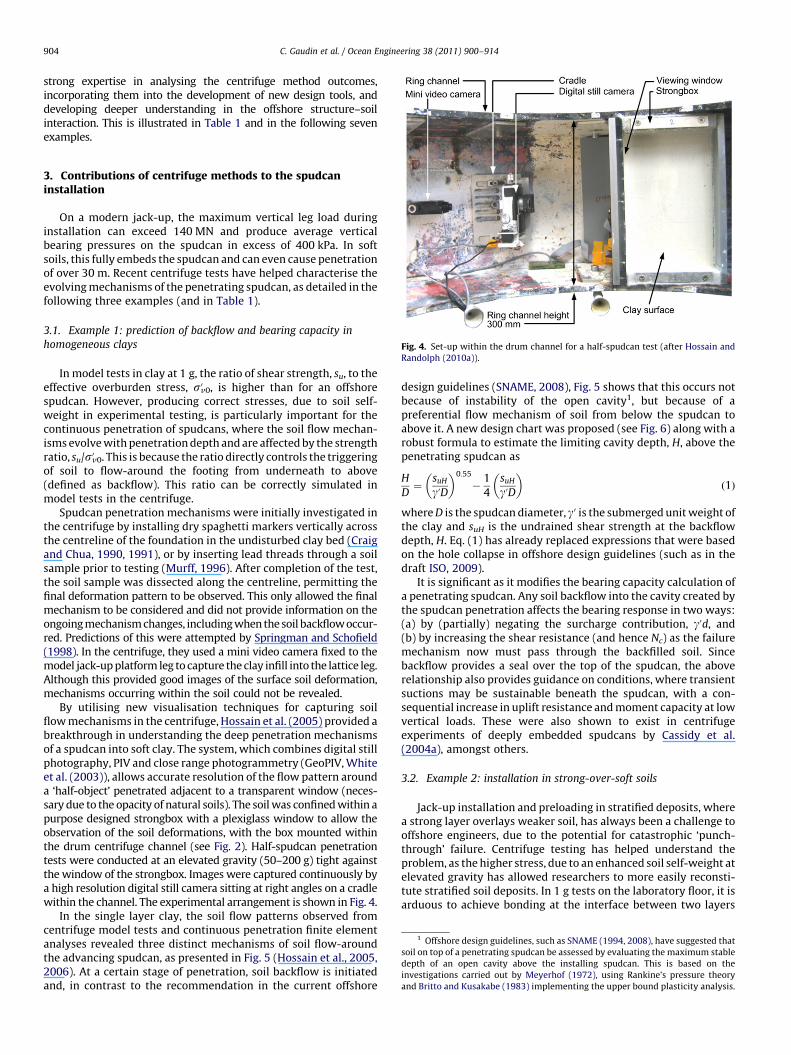
Fig. 4. Set-up within the drum channel for a half-spudcan test (after Hossain and
Randolph (2010a)).
1 Offshore design guidelines, such as SNAME (1994, 2008), have suggested that
soil on top of a penetrating spudcan be assessed by evaluating the maximum stable
depth of an open cavity above the installing spudcan. This is based on the
investigations carried out by Meyerhof (1972), using Rankine’s pressure theory
and Britto and Kusakabe (1983) implementing the upper bound plasticity analysis.
3. Contributions of centrifuge methods to the spudcaninstallation
On a modern jack-up, the maximum vertical leg load duringinstallation can exceed 140 MN and produce average verticalbearing pressures on the spudcan in excess of 400 kPa. In softsoils, this fully embeds the spudcan and can even cause penetrationof over 30 m. Recent centrifuge tests have helped characterise theevolving mechanisms of the penetrating spudcan, as detailed in thefollowing three examples (and in Table 1).
3.1. Example 1: prediction of backflow and bearing capacity in
homogeneous clays
In model tests in clay at 1 g, the ratio of shear strength, su, to theeffective overburden stress, s0v0, is higher than for an offshorespudcan. However, producing correct stresses, due to soil self-weight in experimental testing, is particularly important for thecontinuous penetration of spudcans, where the soil flow mechan-isms evolve with penetration depth and are affected by the strengthratio, su/s0v0. This is because the ratio directly controls the triggeringof soil to flow-around the footing from underneath to above(defined as backflow). This ratio can be correctly simulated inmodel tests in the centrifuge.
Spudcan penetration mechanisms were initially investigated inthe centrifuge by installing dry spaghetti markers vertically acrossthe centreline of the foundation in the undisturbed clay bed (Craigand Chua, 1990, 1991), or by inserting lead threads through a soilsample prior to testing (Murff, 1996). After completion of the test,the soil sample was dissected along the centreline, permitting thefinal deformation pattern to be observed. This only allowed the finalmechanism to be considered and did not provide information on theongoing mechanism changes, including when the soil backflow occur-red. Predictions of this were attempted by Springman and Schofield(1998). In the centrifuge, they used a mini video camera fixed to themodel jack-up platform leg to capture the clay infill into the lattice leg.Although this provided good images of the surface soil deformation,mechanisms occurring within the soil could not be revealed.
By utilising new visualisation techniques for capturing soilflow mechanisms in the centrifuge, Hossain et al. (2005) provided abreakthrough in understanding the deep penetration mechanismsof a spudcan into soft clay. The system, which combines digital stillphotography, PIV and close range photogrammetry (GeoPIV, Whiteet al. (2003)), allows accurate resolution of the flow pattern arounda ‘half-object’ penetrated adjacent to a transparent window (neces-sary due to the opacity of natural soils). The soil was confined within apurpose designed strongbox with a plexiglass window to allow theobservation of the soil deformations, with the box mounted withinthe drum centrifuge channel (see Fig. 2). Half-spudcan penetrationtests were conducted at an elevated gravity (50–200 g) tight againstthe window of the strongbox. Images were captured continuously bya high resolution digital still camera sitting at right angles on a cradlewithin the channel. The experimental arrangement is shown in Fig. 4.
In the single layer clay, the soil flow patterns observed fromcentrifuge model tests and continuous penetration finite elementanalyses revealed three distinct mechanisms of soil flow-aroundthe advancing spudcan, as presented in Fig. 5 (Hossain et al., 2005,2006). At a certain stage of penetration, soil backflow is initiatedand, in contrast to the recommendation in the current offshore
design guidelines (SNAME, 2008), Fig. 5 shows that this occurs notbecause of instability of the open cavity1, but because of apreferential flow mechanism of soil from below the spudcan toabove it. A new design chart was proposed (see Fig. 6) along with arobust formula to estimate the limiting cavity depth, H, above thepenetrating spudcan as
H
D¼
suH
guD
� �0:55
�1
4
suH
guD
� �ð1Þ
where D is the spudcan diameter, g0 is the submerged unit weight ofthe clay and suH is the undrained shear strength at the backflowdepth, H. Eq. (1) has already replaced expressions that were basedon the hole collapse in offshore design guidelines (such as in thedraft ISO, 2009).
It is significant as it modifies the bearing capacity calculation ofa penetrating spudcan. Any soil backflow into the cavity created bythe spudcan penetration affects the bearing response in two ways:(a) by (partially) negating the surcharge contribution, g0d, and(b) by increasing the shear resistance (and hence Nc) as the failuremechanism now must pass through the backfilled soil. Sincebackflow provides a seal over the top of the spudcan, the aboverelationship also provides guidance on conditions, where transientsuctions may be sustainable beneath the spudcan, with a con-sequential increase in uplift resistance and moment capacity at lowvertical loads. These were also shown to exist in centrifugeexperiments of deeply embedded spudcans by Cassidy et al.(2004a), amongst others.
3.2. Example 2: installation in strong-over-soft soils
Jack-up installation and preloading in stratified deposits, wherea strong layer overlays weaker soil, has always been a challenge tooffshore engineers, due to the potential for catastrophic ‘punch-through’ failure. Centrifuge testing has helped understand theproblem, as the higher stress, due to an enhanced soil self-weight atelevated gravity has allowed researchers to more easily reconsti-tute stratified soil deposits. In 1 g tests on the laboratory floor, it isarduous to achieve bonding at the interface between two layers
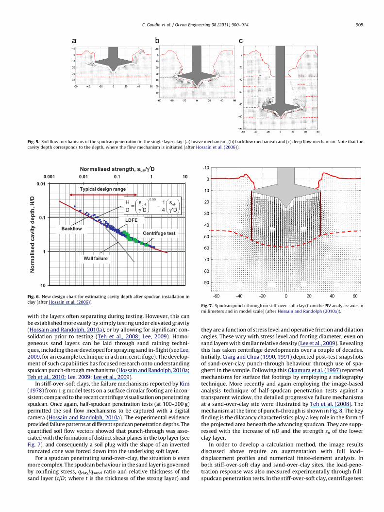
0.01
0.1
1
10
0.001 0.01 0.1 1 10Normalised strength, suH/γγ ′′′D
Nor
mal
ised
cav
ity d
epth
, H/D
Typical design range
Centrifuge test
LDFE
γ ′−
γ ′= s
41
Ds
DH uH
Wall failure
Backflow
0.55
DuH
Fig. 6. New design chart for estimating cavity depth after spudcan installation in
clay (after Hossain et al. (2006)).Fig. 7. Spudcan punch-through on stiff-over-soft clay (from the PIV analysis: axes in
millimeters and in model scale) (after Hossain and Randolph (2010a)).
Fig. 5. Soil flow mechanisms of the spudcan penetration in the single layer clay: (a) heave mechanism, (b) backflow mechanism and (c) deep flow mechanism. Note that the
cavity depth corresponds to the depth, where the flow mechanism is initiated (after Hossain et al. (2006)).
C. Gaudin et al. / Ocean Engineering 38 (2011) 900–914 905
with the layers often separating during testing. However, this canbe established more easily by simply testing under elevated gravity(Hossain and Randolph, 2010a), or by allowing for significant con-solidation prior to testing (Teh et al., 2008; Lee, 2009). Homo-geneous sand layers can be laid through sand raining techni-ques, including those developed for spraying sand in-flight (see Lee,2009, for an example technique in a drum centrifuge). The develop-ment of such capabilities has focused research onto understandingspudcan punch-through mechanisms (Hossain and Randolph, 2010a;Teh et al., 2010; Lee, 2009; Lee et al., 2009).
In stiff-over-soft clays, the failure mechanisms reported by Kim(1978) from 1 g model tests on a surface circular footing are incon-sistent compared to the recent centrifuge visualisation on penetratingspudcan. Once again, half-spudcan penetration tests (at 100–200 g)permitted the soil flow mechanisms to be captured with a digitalcamera (Hossain and Randolph, 2010a). The experimental evidenceprovided failure patterns at different spudcan penetration depths. Thequantified soil flow vectors showed that punch-through was asso-ciated with the formation of distinct shear planes in the top layer (seeFig. 7), and consequently a soil plug with the shape of an invertedtruncated cone was forced down into the underlying soft layer.
For a spudcan penetrating sand-over-clay, the situation is evenmore complex. The spudcan behaviour in the sand layer is governedby confining stress, qclay/qsand ratio and relative thickness of thesand layer (t/D; where t is the thickness of the strong layer) and
they are a function of stress level and operative friction and dilationangles. These vary with stress level and footing diameter, even onsand layers with similar relative density (Lee et al., 2009). Revealingthis has taken centrifuge developments over a couple of decades.Initially, Craig and Chua (1990, 1991) depicted post-test snapshotsof sand-over-clay punch-through behaviour through use of spa-ghetti in the sample. Following this Okamura et al. (1997) reportedmechanisms for surface flat footings by employing a radiographytechnique. More recently and again employing the image-basedanalysis technique of half-spudcan penetration tests against atransparent window, the detailed progressive failure mechanismsat a sand-over-clay site were illustrated by Teh et al. (2008). Themechanism at the time of punch-through is shown in Fig. 8. The keyfinding is the dilatancy characteristics play a key role in the form ofthe projected area beneath the advancing spudcan. They are supp-ressed with the increase of t/D and the strength su of the lowerclay layer.
In order to develop a calculation method, the image resultsdiscussed above require an augmentation with full load–displacement profiles and numerical finite-element analysis. Inboth stiff-over-soft clay and sand-over-clay sites, the load-pene-tration response was also measured experimentally through full-spudcan penetration tests. In the stiff-over-soft clay, centrifuge test
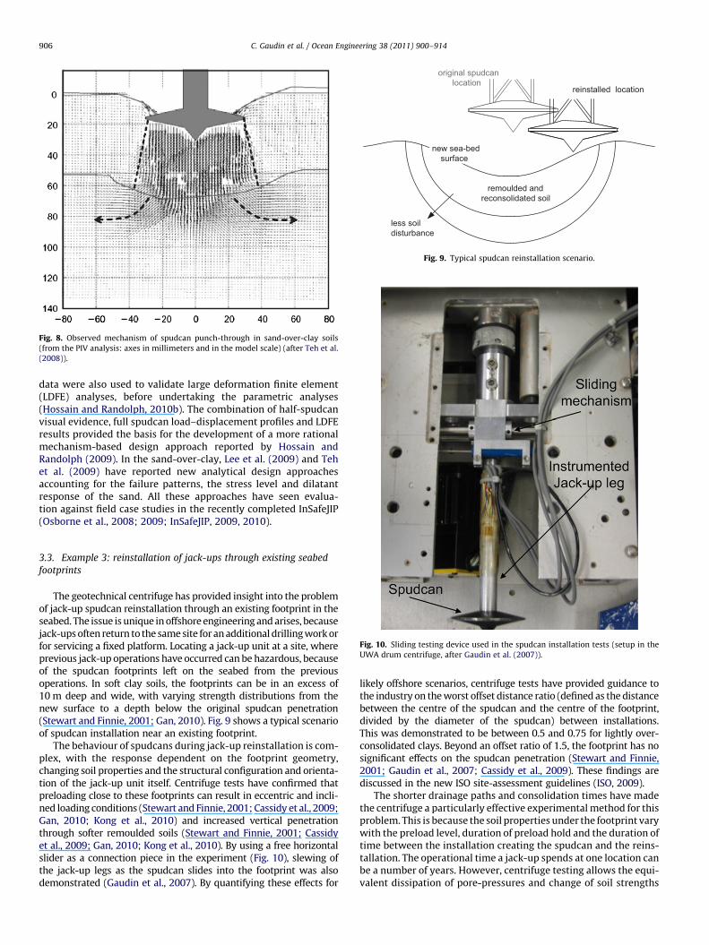
Fig. 8. Observed mechanism of spudcan punch-through in sand-over-clay soils
(from the PIV analysis: axes in millimeters and in the model scale) (after Teh et al.
(2008)).
original spudcan location
reinstalled location
remoulded and reconsolidated soil
less soil disturbance
new sea-bed surface
Fig. 9. Typical spudcan reinstallation scenario.
C. Gaudin et al. / Ocean Engineering 38 (2011) 900–914906
data were also used to validate large deformation finite element(LDFE) analyses, before undertaking the parametric analyses(Hossain and Randolph, 2010b). The combination of half-spudcanvisual evidence, full spudcan load–displacement profiles and LDFEresults provided the basis for the development of a more rationalmechanism-based design approach reported by Hossain andRandolph (2009). In the sand-over-clay, Lee et al. (2009) and Tehet al. (2009) have reported new analytical design approachesaccounting for the failure patterns, the stress level and dilatantresponse of the sand. All these approaches have seen evalua-tion against field case studies in the recently completed InSafeJIP(Osborne et al., 2008; 2009; InSafeJIP, 2009, 2010).
Fig. 10. Sliding testing device used in the spudcan installation tests (setup in the
UWA drum centrifuge, after Gaudin et al. (2007)).
3.3. Example 3: reinstallation of jack-ups through existing seabed
footprints
The geotechnical centrifuge has provided insight into the problemof jack-up spudcan reinstallation through an existing footprint in theseabed. The issue is unique in offshore engineering and arises, becausejack-ups often return to the same site for an additional drilling work orfor servicing a fixed platform. Locating a jack-up unit at a site, whereprevious jack-up operations have occurred can be hazardous, becauseof the spudcan footprints left on the seabed from the previousoperations. In soft clay soils, the footprints can be in an excess of10 m deep and wide, with varying strength distributions from thenew surface to a depth below the original spudcan penetration(Stewart and Finnie, 2001; Gan, 2010). Fig. 9 shows a typical scenarioof spudcan installation near an existing footprint.
The behaviour of spudcans during jack-up reinstallation is com-plex, with the response dependent on the footprint geometry,changing soil properties and the structural configuration and orienta-tion of the jack-up unit itself. Centrifuge tests have confirmed thatpreloading close to these footprints can result in eccentric and incli-ned loading conditions (Stewart and Finnie, 2001; Cassidy et al., 2009;Gan, 2010; Kong et al., 2010) and increased vertical penetrationthrough softer remoulded soils (Stewart and Finnie, 2001; Cassidyet al., 2009; Gan, 2010; Kong et al., 2010). By using a free horizontalslider as a connection piece in the experiment (Fig. 10), slewing ofthe jack-up legs as the spudcan slides into the footprint was alsodemonstrated (Gaudin et al., 2007). By quantifying these effects for
likely offshore scenarios, centrifuge tests have provided guidance tothe industry on the worst offset distance ratio (defined as the distancebetween the centre of the spudcan and the centre of the footprint,divided by the diameter of the spudcan) between installations.This was demonstrated to be between 0.5 and 0.75 for lightly over-consolidated clays. Beyond an offset ratio of 1.5, the footprint has nosignificant effects on the spudcan penetration (Stewart and Finnie,2001; Gaudin et al., 2007; Cassidy et al., 2009). These findings arediscussed in the new ISO site-assessment guidelines (ISO, 2009).
The shorter drainage paths and consolidation times have madethe centrifuge a particularly effective experimental method for thisproblem. This is because the soil properties under the footprint varywith the preload level, duration of preload hold and the duration oftime between the installation creating the spudcan and the reins-tallation. The operational time a jack-up spends at one location canbe a number of years. However, centrifuge testing allows the equi-valent dissipation of pore-pressures and change of soil strengths
C. Gaudin et al. / Ocean Engineering 38 (2011) 900–914 907
within the footprint in a matter of hours. Leung et al. (2007), Ganet al. (2008) and Gan (2010) have effectively used the centrifuge tostudy the change in soil properties of footprints, for both normallyconsolidated and over-consolidated soils, reporting contours ofstrength loss and gain. These new profiles of shear strength criticallyaffect the behaviour of the spudcan on reinstallation, as the shearstrength is now varying in both the vertical and horizontal directions.
Fig. 11. Yield surface as established from the single footing experiments in the
centrifuge (after Cassidy (2007)).
4. Contributions of centrifuge methods to jack-up operations
Assessment of the operational phase of jack-up deploymentrequires analytical models that can predict the ultimate load capa-city and the corresponding displacements. For structures such asjack-ups, the behaviour of the individual footings significantly influ-ences the overall system response. The foundation behaviour is furtherload-path dependent. Therefore, accurate modelling of the non-linearload–displacement relationship of the spudcans is crucial to the pre-diction of the global structural response, under working loads as wellas at an ultimate capacity. The use of centrifuge technology in thedevelopment of single footing analytical models and their verificationin the structural push-over analysis of three-legged jack-ups is descri-bed in the following examples 4 and 5, respectively.
4.1. Example 4: development of force-resultant models for combined
loading
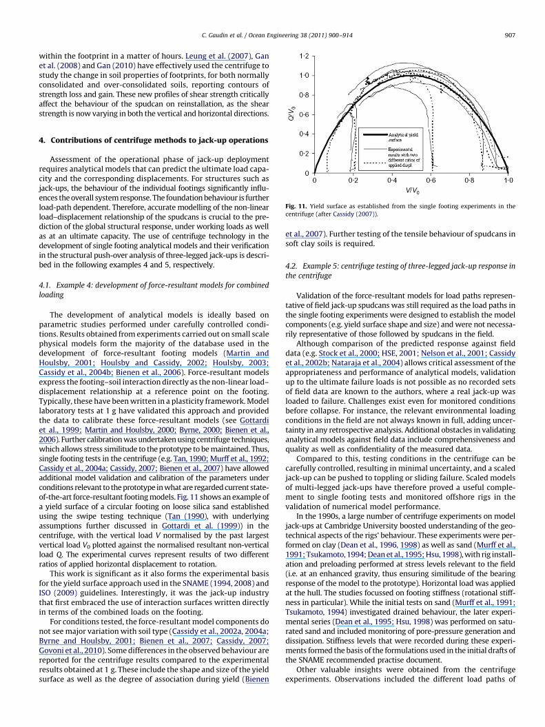
The development of analytical models is ideally based onparametric studies performed under carefully controlled condi-tions. Results obtained from experiments carried out on small scalephysical models form the majority of the database used in thedevelopment of force-resultant footing models (Martin andHoulsby, 2001; Houlsby and Cassidy, 2002; Houlsby, 2003;Cassidy et al., 2004b; Bienen et al., 2006). Force-resultant modelsexpress the footing–soil interaction directly as the non-linear load–displacement relationship at a reference point on the footing.Typically, these have been written in a plasticity framework. Modellaboratory tests at 1 g have validated this approach and providedthe data to calibrate these force-resultant models (see Gottardiet al., 1999; Martin and Houlsby, 2000; Byrne, 2000; Bienen et al.,2006). Further calibration was undertaken using centrifuge techniques,which allows stress similitude to the prototype to be maintained. Thus,single footing tests in the centrifuge (e.g. Tan, 1990; Murff et al., 1992;Cassidy et al., 2004a; Cassidy, 2007; Bienen et al., 2007) have allowedadditional model validation and calibration of the parameters underconditions relevant to the prototype in what are regarded current state-of-the-art force-resultant footing models. Fig. 11 shows an example ofa yield surface of a circular footing on loose silica sand establishedusing the swipe testing technique (Tan (1990), with underlyingassumptions further discussed in Gottardi et al. (1999)) in thecentrifuge, with the vertical load V normalised by the past largestvertical load V0 plotted against the normalised resultant non-verticalload Q. The experimental curves represent results of two differentratios of applied horizontal displacement to rotation.
This work is significant as it also forms the experimental basisfor the yield surface approach used in the SNAME (1994, 2008) andISO (2009) guidelines. Interestingly, it was the jack-up industrythat first embraced the use of interaction surfaces written directlyin terms of the combined loads on the footing.
For conditions tested, the force-resultant model components donot see major variation with soil type (Cassidy et al., 2002a, 2004a;Byrne and Houlsby, 2001; Bienen et al., 2007; Cassidy, 2007;Govoni et al., 2010). Some differences in the observed behaviour arereported for the centrifuge results compared to the experimentalresults obtained at 1 g. These include the shape and size of the yieldsurface as well as the degree of association during yield (Bienen
et al., 2007). Further testing of the tensile behaviour of spudcans insoft clay soils is required.
4.2. Example 5: centrifuge testing of three-legged jack-up response in
the centrifuge
Validation of the force-resultant models for load paths represen-tative of field jack-up spudcans was still required as the load paths inthe single footing experiments were designed to establish the modelcomponents (e.g. yield surface shape and size) and were not necessa-rily representative of those followed by spudcans in the field.
Although comparison of the predicted response against fielddata (e.g. Stock et al., 2000; HSE, 2001; Nelson et al., 2001; Cassidyet al., 2002b; Nataraja et al., 2004) allows critical assessment of theappropriateness and performance of analytical models, validationup to the ultimate failure loads is not possible as no recorded setsof field data are known to the authors, where a real jack-up wasloaded to failure. Challenges exist even for monitored conditionsbefore collapse. For instance, the relevant environmental loadingconditions in the field are not always known in full, adding uncer-tainty in any retrospective analysis. Additional obstacles in validatinganalytical models against field data include comprehensiveness andquality as well as confidentiality of the measured data.
Compared to this, testing conditions in the centrifuge can becarefully controlled, resulting in minimal uncertainty, and a scaledjack-up can be pushed to toppling or sliding failure. Scaled modelsof multi-legged jack-ups have therefore proved a useful comple-ment to single footing tests and monitored offshore rigs in thevalidation of numerical model performance.
In the 1990s, a large number of centrifuge experiments on modeljack-ups at Cambridge University boosted understanding of the geo-technical aspects of the rigs’ behaviour. These experiments were per-formed on clay (Dean et al., 1996, 1998) as well as sand (Murff et al.,1991; Tsukamoto, 1994; Dean et al., 1995; Hsu, 1998), with rig install-ation and preloading performed at stress levels relevant to the field(i.e. at an enhanced gravity, thus ensuring similitude of the bearingresponse of the model to the prototype). Horizontal load was appliedat the hull. The studies focussed on footing stiffness (rotational stiff-ness in particular). While the initial tests on sand (Murff et al., 1991;Tsukamoto, 1994) investigated drained behaviour, the later experi-mental series (Dean et al., 1995; Hsu, 1998) was performed on satu-rated sand and included monitoring of pore-pressure generation anddissipation. Stiffness levels that were recorded during these experi-ments formed the basis of the formulations used in the initial drafts ofthe SNAME recommended practise document.
Other valuable insights were obtained from the centrifugeexperiments. Observations included the different load paths of
Strain gauges
Strain gauges
Pulley (pull-over load application)
Application of preload Displacement
sensor
Leg A
Leg C Leg B
Fig. 13. Model jack-up for testing in the centrifuge (after Bienen (2009)).
C. Gaudin et al. / Ocean Engineering 38 (2011) 900–914908
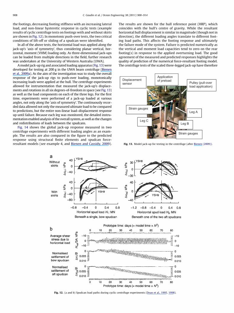
the footings, decreasing footing stiffness with an increasing lateralload, and non-linear hysteretic response in cyclic tests (exampleresults of cyclic centrifuge tests on footings with and without skirtsare shown in Fig. 12). In monotonic push-over tests, the two criticalconditions of lift-off or sliding of a spudcan were identified.
In all of the above tests, the horizontal load was applied along thejack-up’s ‘axis of symmetry’, thus considering planar vertical, hor-izontal, moment (VHM) loading only. As three-dimensional jack-upscan be loaded from multiple directions in the field, further researchwas undertaken at the University of Western Australia (UWA).
A model jack-up rig and associated loading apparatus (Fig. 13) weredeveloped for testing at 200 g in the UWA beam centrifuge (Bienenet al., 2009a). As the aim of the investigation was to study the overallresponse of the jack-up rigs to push-over loading, monotonicallyincreasing loads were applied at the hull. The centrifuge experimentsallowed for instrumentation that measured the jack-up’s displace-ments and rotations in all six degrees-of-freedom in space (see Fig. 13)as well as the load components on each of the three legs. For the firsttime, experiments were performed of a jack-up loaded at variousangles, not only along the ‘axis of symmetry’. The continuously recor-ded data allowed not only the measured ultimate load to be comparedto predictions, but the entire non-linear load–displacement responseup until failure. Because each leg was monitored, the detailed instru-mentation enabled analysis of the overall system, as well as the changesand redistributions of loads between the spudcans.
Fig. 14 shows the global jack-up response measured in twocentrifuge experiments with different loading angles as an exam-ple. The results are also compared in the figure to the predictedresponse using structural finite elements and spudcan force-resultant models (see example 4, and Bienen and Cassidy, 2009).
Fig. 12. (a and b) Spudcan load paths during cyclic c
The results are shown for the hull reference point (HRP), whichcoincides with the hull’s centre of gravity. While the resultanthorizontal hull displacement is similar in magnitude (though not indirection), the different loading angles translate to different foot-ing load paths. This affects the footing response and ultimatelythe failure mode of the system. Failure is predicted numerically asthe vertical and moment load capacities tend to zero on the rearfooting(s) in response to the applied overturning load. The goodagreement of the measured and predicted responses highlights thequality of prediction of the numerical force-resultant footing model.The centrifuge tests of the scaled three-legged jack-up have therefore
entrifuge experiments (Dean et al., 1995, 1998).

0.0
5.0
10.0
15.0
20.0
25.0
0.0 0.5 1.0 1.5 2.0 2.5 3.0 3.5 4.0Resultant horizontal displacement at the HRP [m]
App
lied
load
[MN
]
Exp., Test 1
Exp., Test 2
Num., Test 1Num., Test 2
Failure load Test 1 (22.0 MN)
Max. applied load Test 2 (17.9 MN)
Fig. 14. Measured and predicted global jack-up response (after Bienen and Cassidy (2009)).
C. Gaudin et al. / Ocean Engineering 38 (2011) 900–914 909
added much confidence to the use of these force-resultant models foroffshore conditions (as recommended in a ‘‘Step 3’’ analysis in theSNAME or ISO documents).
Fig. 15. Visualisation of soil failure mechanism during spudcan extraction (after
Purwana et al. (2008)).
5. Contributions of centrifuge methods to the spudcanextraction
Spudcan extraction often proves difficult and time-consuming inthe field, especially in soft soils, where deep penetrations are ex-perienced. As no guidelines are currently available for the spudcanextraction, various strategies to free the leg are usually employedthrough a trial and error process (InSafeJIP, 2009). Therefore, the keycontributing factors to a successful extraction have remained uncertainto the jack-up industry. Aspects that increase the level of complexity inunderstanding spudcan extraction in the field include highly stratifiedsoil conditions, difficulties in quantifying the changes in soil strengthdue to disturbance and reconsolidation, sometimes unquantifiablewave excitations, as well as difficulties in measuring the loadingexerted during the extraction process on the jack-up. In order todevelop sound predictive methods for the expected resistance and todevise successful extraction procedures, the governing soil failuremechanisms must first be established.
As detailed in the following examples 6 and 7, centrifuge modell-ing has recently provided an evidence of these extraction mechanismsand analytical models have been developed based on these results.
5.1. Example 6: failure mechanisms and resistance components
during the spudcan extraction
As was shown in examples 1 and 3, soil failure mechanisms can bevisualised by testing half models against a transparent window incombination with PIV and photogrammetry. Purwana et al. (2006,2008, 2009) employed this technique to gain insight into soil failuremechanisms during the spudcan extraction, an example of which isshown in Fig. 15. In the left half of the figure, the photo taken during theextraction test is presented, showing the spudcan and the clay to whichthe coloured flock was added to allow for better visualisation of the soilmovement. The right half of the figure depicts the correspondingvectors of soil displacement as obtained from the PIV analysis. Theresults have proven valuable in determining the soil displacementpattern and understanding the mobilisation of soil resistance duringthe spudcan extraction. Importantly, the effect on extraction of soil
remoulding and consolidation during installation, preloading andholding of self-weight during operation could all be modelled in atimely manner in the centrifuge.
The centrifuge data can also be used as a basis for the develop-ment of predictive methods. Such a model for the spudcan extractionresistance was proposed by Purwana et al. (2009). It was developedbased on centrifuge extraction data from the spudcan embedments ofup to 1.5 diameters, and utilised experimental recordings of resistanceat both the spudcan top and base, as well as pore-pressures. A similarformulation for calculating the extraction resistance was adopted inthe InSafeJIP (2010) guidelines, also calibrated against centrifuge data.
5.2. Example 7: extraction with water jetting
Especially when an insufficient uplift load is available throughthe jack-up hull buoyancy, water jetting may ease the spudcanextraction. Jetting with nozzles located at the spudcan top faceaims at reducing resistance to an extraction through fracturing andremoulding the soil. Jetting with nozzles at the spudcan invert(i.e. the base of the spudcan), on the other hand, aims at decreasingthe negative pore-pressures mobilised by the uplifting spudcan.This can extend to creating positive excess pore-pressures at thespudcan invert, applying an additional active uplift force.
0.0
0.1
0.2
0.3
0.4
0.5
0.6
0.7
0.8
0.9
1.0
0.0 0.1 0.2 0.3 0.4
Fillin
Fig. 17. Conceptual chart of jetting extraction efficiency. The chart indicates, for a given extracti
Fig. 16. Model spudcan for extraction tests with water jetting (after Gaudin et al.
(2010a)). (a) spudcan base with jetting nozzles and deflectors and (b) water jetting in
model spudcan.
C. Gaudin et al. / Ocean Engineering 38 (2011) 900–914910
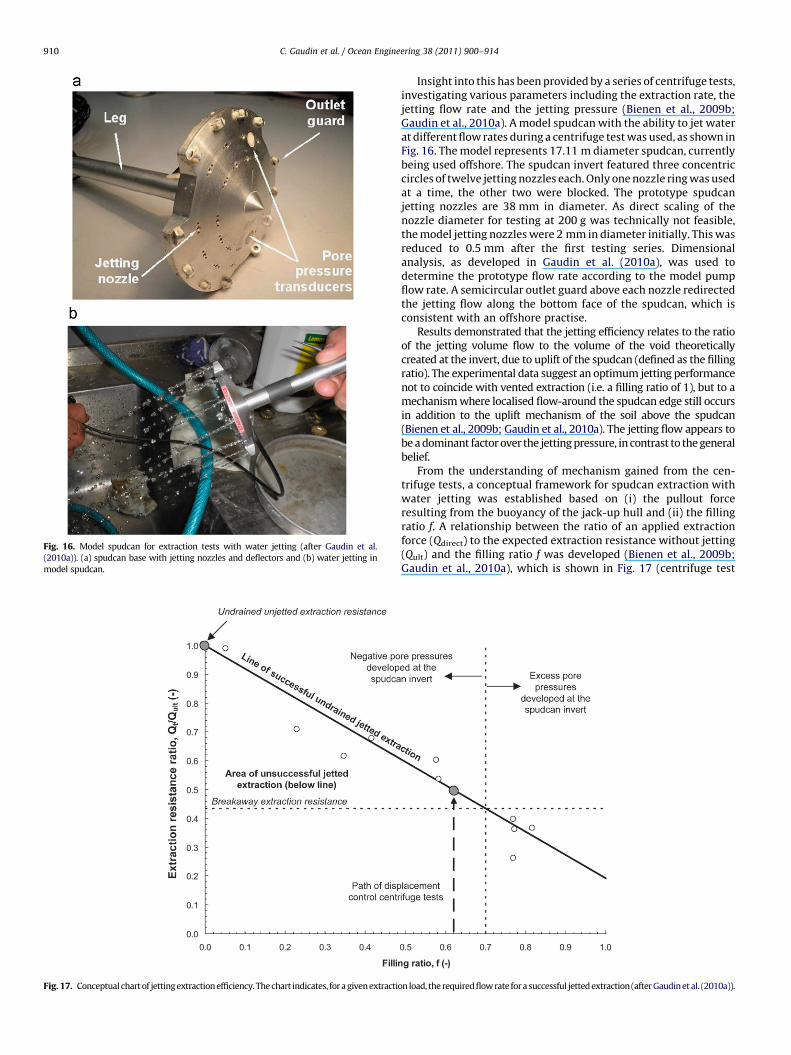
Insight into this has been provided by a series of centrifuge tests,investigating various parameters including the extraction rate, thejetting flow rate and the jetting pressure (Bienen et al., 2009b;Gaudin et al., 2010a). A model spudcan with the ability to jet waterat different flow rates during a centrifuge test was used, as shown inFig. 16. The model represents 17.11 m diameter spudcan, currentlybeing used offshore. The spudcan invert featured three concentriccircles of twelve jetting nozzles each. Only one nozzle ring was usedat a time, the other two were blocked. The prototype spudcanjetting nozzles are 38 mm in diameter. As direct scaling of thenozzle diameter for testing at 200 g was technically not feasible,the model jetting nozzles were 2 mm in diameter initially. This wasreduced to 0.5 mm after the first testing series. Dimensionalanalysis, as developed in Gaudin et al. (2010a), was used todetermine the prototype flow rate according to the model pumpflow rate. A semicircular outlet guard above each nozzle redirectedthe jetting flow along the bottom face of the spudcan, which isconsistent with an offshore practise.
Results demonstrated that the jetting efficiency relates to the ratioof the jetting volume flow to the volume of the void theoreticallycreated at the invert, due to uplift of the spudcan (defined as the fillingratio). The experimental data suggest an optimum jetting performancenot to coincide with vented extraction (i.e. a filling ratio of 1), but to amechanism where localised flow-around the spudcan edge still occursin addition to the uplift mechanism of the soil above the spudcan(Bienen et al., 2009b; Gaudin et al., 2010a). The jetting flow appears tobe a dominant factor over the jetting pressure, in contrast to the generalbelief.
From the understanding of mechanism gained from the cen-trifuge tests, a conceptual framework for spudcan extraction withwater jetting was established based on (i) the pullout forceresulting from the buoyancy of the jack-up hull and (ii) the fillingratio f. A relationship between the ratio of an applied extractionforce (Qdirect) to the expected extraction resistance without jetting(Qult) and the filling ratio f was developed (Bienen et al., 2009b;Gaudin et al., 2010a), which is shown in Fig. 17 (centrifuge test
0.5 0.6 0.7 0.8 0.9 1.0
g ratio, f (-)
on load, the required flow rate for a successful jetted extraction (after Gaudin et al. (2010a)).
C. Gaudin et al. / Ocean Engineering 38 (2011) 900–914 911
results are represented by the open circles). The filling ratio can berelated to the required parameter in the field, the jetting flow rate.
6. Future opportunities for application of the centrifuge
This paper has highlighted some of the advances made throughthe use of centrifuge methods in understanding the jack-upbehaviour. With the jack-up industry moving to new areas withmore challenging soil conditions, further research is required.There are significant opportunities for the centrifuge to contributeto new understanding and to scientifically underpin the analysismethods. The following opportunities have been identified:
�
Figpen
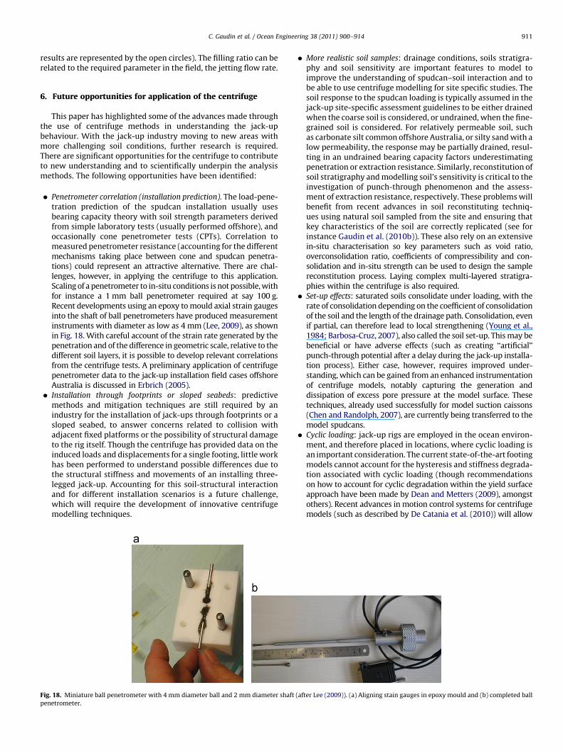
Penetrometer correlation (installation prediction). The load-pene-tration prediction of the spudcan installation usually usesbearing capacity theory with soil strength parameters derivedfrom simple laboratory tests (usually performed offshore), andoccasionally cone penetrometer tests (CPTs). Correlation tomeasured penetrometer resistance (accounting for the differentmechanisms taking place between cone and spudcan penetra-tions) could represent an attractive alternative. There are chal-lenges, however, in applying the centrifuge to this application.Scaling of a penetrometer to in-situ conditions is not possible, withfor instance a 1 mm ball penetrometer required at say 100 g.Recent developments using an epoxy to mould axial strain gaugesinto the shaft of ball penetrometers have produced measurementinstruments with diameter as low as 4 mm (Lee, 2009), as shownin Fig. 18. With careful account of the strain rate generated by thepenetration and of the difference in geometric scale, relative to thedifferent soil layers, it is possible to develop relevant correlationsfrom the centrifuge tests. A preliminary application of centrifugepenetrometer data to the jack-up installation field cases offshoreAustralia is discussed in Erbrich (2005).
� Installation through footprints or sloped seabeds: predictivemethods and mitigation techniques are still required by anindustry for the installation of jack-ups through footprints or asloped seabed, to answer concerns related to collision withadjacent fixed platforms or the possibility of structural damageto the rig itself. Though the centrifuge has provided data on theinduced loads and displacements for a single footing, little workhas been performed to understand possible differences due tothe structural stiffness and movements of an installing three-legged jack-up. Accounting for this soil-structural interactionand for different installation scenarios is a future challenge,which will require the development of innovative centrifugemodelling techniques.
. 18. Miniature ball penetrometer with 4 mm diameter ball and 2 mm diameter shaft
etrometer.
�
(aft
More realistic soil samples: drainage conditions, soils stratigra-phy and soil sensitivity are important features to model toimprove the understanding of spudcan–soil interaction and tobe able to use centrifuge modelling for site specific studies. Thesoil response to the spudcan loading is typically assumed in thejack-up site-specific assessment guidelines to be either drainedwhen the coarse soil is considered, or undrained, when the fine-grained soil is considered. For relatively permeable soil, suchas carbonate silt common offshore Australia, or silty sand with alow permeability, the response may be partially drained, resul-ting in an undrained bearing capacity factors underestimatingpenetration or extraction resistance. Similarly, reconstitution ofsoil stratigraphy and modelling soil’s sensitivity is critical to theinvestigation of punch-through phenomenon and the assess-ment of extraction resistance, respectively. These problems willbenefit from recent advances in soil reconstituting techniq-ues using natural soil sampled from the site and ensuring thatkey characteristics of the soil are correctly replicated (see forinstance Gaudin et al. (2010b)). These also rely on an extensivein-situ characterisation so key parameters such as void ratio,overconsolidation ratio, coefficients of compressibility and con-solidation and in-situ strength can be used to design the samplereconstitution process. Laying complex multi-layered stratigra-phies within the centrifuge is also required.
� Set-up effects: saturated soils consolidate under loading, with therate of consolidation depending on the coefficient of consolidationof the soil and the length of the drainage path. Consolidation, evenif partial, can therefore lead to local strengthening (Young et al.,1984; Barbosa-Cruz, 2007), also called the soil set-up. This may bebeneficial or have adverse effects (such as creating ‘‘artificial’’punch-through potential after a delay during the jack-up installa-tion process). Either case, however, requires improved under-standing, which can be gained from an enhanced instrumentationof centrifuge models, notably capturing the generation anddissipation of excess pore pressure at the model surface. Thesetechniques, already used successfully for model suction caissons(Chen and Randolph, 2007), are currently being transferred to themodel spudcans.
� Cyclic loading: jack-up rigs are employed in the ocean environ-ment, and therefore placed in locations, where cyclic loading isan important consideration. The current state-of-the-art footingmodels cannot account for the hysteresis and stiffness degrada-tion associated with cyclic loading (though recommendationson how to account for cyclic degradation within the yield surfaceapproach have been made by Dean and Metters (2009), amongstothers). Recent advances in motion control systems for centrifugemodels (such as described by De Catania et al. (2010)) will allow
er Lee (2009)). (a) Aligning stain gauges in epoxy mould and (b) completed ball
C. Gaudin et al. / Ocean Engineering 38 (2011) 900–914912
cyclic loading of an entire storm, or multiple storms over the life ofan installed jack-up, to be applied.
� Spudcan extraction: while recent research has advanced ourunderstanding of spudcan extraction, more comprehensive under-standing of the development of effective stresses around a spudcanis desirable, both for unaided extractions and for those using waterjetting. Evaluation of required jetting volumes (base jetting) orpressures (top jetting) is expected to relate to the evolution ofeffective stresses around the spudcan. Current methods for basejetting are limited to a narrow set of boundary conditions andrequire further validation for other situations. Furthermore, thecurrent knowledge is restricted to the failure mechanisms thatdevelop at a relatively narrow range of spudcan embedment in softclay. Furthermore, the effect of small amplitude wave loading andresulting cyclic loading on the spudcan extraction is currently notunderstood. The centrifuge technology required to investigatethese issues is available.
For all these opportunities, centrifuge methods will play a role inboth increasing understanding of the soil–structure interaction andthe development of thorough predictive methods. However, thereis also a need to calibrate any new procedures against offshore fieldmeasurements, as an application of new predictive methods tohighly complex and stratified seabeds is always a challenge.
7. Conclusions
Centrifuge modelling techniques have played an integral rolein developing new design and assessment methods for jack-upspudcan foundations, many of which have been incorporated intoindustry guidelines. This paper provides a review of recent con-tributions covering all three phases of the jack-up installation, in-situ operations and jack-up extraction. Areas where the centrifugehas directly influenced an industry practise, particularly in chan-ging recommended SNAME and ISO procedures and the recentintroduction of the InSafeJIP guidelines, have been highlightedthroughout the paper.
As centrifuge technology itself develops, further opportunitieswill be created for solving the emerging issues faced by the jack-upindustry, as they move into deeper water and more challengingseabed conditions. Some of the opportunities for the near futurehave been showcased in this paper, and include amongst others:direct prediction of jack-up installations using penetrometer data,installation through footprints and sloped seabeds, spudcan beha-viour in multi-layered and intermediate silty soils and operationalprocedures for jetted spudcan extraction.
The geotechnical centrifuge will continue to provide pivotalinsights into the spudcan behaviour, but should not be considereda stand-alone tool. Analytical methods developed through centrifugedata offer maximum benefit when considered together with numer-ical methods and field data. The latter is increasingly being collectedoffshore and will play a critical role in the calibration and validation ofcentrifuge outcomes to the more complex field conditions.
Acknowledgements
The authors acknowledge the sponsorship of the COFS compo-nents of research covered in this review, including from the KeppelOffshore and Marine, Woodside Energy Limited and the AustralianResearch Council. The second author is the grateful recipient of anAustralian Research Council Future Fellowship. The authors acknowl-edge and thank the anonymous reviewers, whose comments andsuggestions significantly enhanced the content of the paper.
References
Barbosa-Cruz, E.R., 2007. Partial consolidation and breakthrough of shallowfoundations in soft soil. Ph.D. Thesis, The University of Western Australia.
Bienen, B., 2009. Predicting the load–displacement response of a mobile jack-updrilling rig on sand. Australian Geomechanics 44 (4), 1–12.
Bienen, B., Byrne, B., Houlsby, G.T., Cassidy, M.J., 2006. Investigating six degree-of-freedom loading of shallow foundations on sand. Geotechnique 56 (6),367–379.
Bienen, B., Cassidy, M.J., 2009. Three-dimensional numerical analysis of centrifugeexperiments on a model jack-up drilling rig on sand. Canadian GeotechnicalJournal 46 (2), 208–224.
Bienen, B., Cassidy, M.J., Gaudin, C., 2009a. Physical modelling of the push-overcapacity of a jack-up structure on sand in a geotechnical centrifuge. CanadianGeotechnical Journal 46 (2), 190–207.
Bienen, B., Gaudin, C., Cassidy, M.J., 2007. Centrifuge tests of shallow footingbehaviour on sand under combined vertical–torsional loading. InternationalJournal of Physical Modelling in Geotechnics 7 (2), 1–21.
Bienen, B., Gaudin, C., Cassidy, M.J., 2009b. The influence of pull-out load on theefficiency of jetting during spudcan extraction. Applied Ocean Research 31 (3),202–211.
Britto, A.M., Kusakabe, O., 1983. Stability of axisymmetric excavations in clays.Journal of Geotechnical Engineering, ASCE 109 (5), 666–681.
Byrne, B.W., 2000. Investigations of suction caissons in dense sand. D.Phil. Thesis,University of Oxford.
Byrne, B.W., Houlsby, G.T., 2001. Observations of footing behaviour on loosecarbonate sands. Geotechnique 51 (5), 463–466.
Cassidy, M.J., 2007. Experimental observations of the combined loading behaviour ofcircular footings on loose silica sand. Geotechnique 57 (4), 397–401.
Cassidy, M.J., Byrne, B.W., Houlsby, G.T., 2002a. Modelling the behaviour of circularfootings under combined loading on loose carbonate sand. Geotechnique 52(10), 705–712.
Cassidy, M.J., Byrne, B.W., Randolph, M.F., 2004a. A comparison of the combined loadbehaviour of spudcan and caisson foundations on soft normally consolidatedclay. Geotechnique 54 (2), 91–106.
Cassidy, M.J., Houlsby, G.T., Hoyle, M., Marcom, M., 2002b. Determining appropriatestiffness levels for spudcan foundations using jack-up case records. In:Proceedings of the 21st International Conference on Offshore Mechanics andArctic Engineering (OMAE), Oslo, Norway, OMAE2002-28085.
Cassidy, M.J., Martin, C.M., Houlsby, G.T., 2004b. Development and application offorce resultant models describing jack-up foundation behaviour. MarineStructures 17, 165–193.
Cassidy, M.J., Quah, C.K., Foo, K.S., 2009. Experimental investigation of thereinstallation of spudcan footings close to existing footprints. Journal ofGeotechnical and Geoenvironmental Engineering, ASCE 135 (4), 474–486.
Chen, W., Randolph, M.F., 2007. Radial stress changes and axial capacity for suctioncaissons in soft clay. Geotechnique 57 (6), 499–511.
Craig, W.H.,. 1984. Preface. In: Proceedings of the International SymposiumApplication of Centrifuge Modelling to Geotechnical Design, Manchester, UK, 1.
Craig, W.H., Al-Saoudi, N.K.S., 1981. The behaviour of some model offshorestructures. In: Proceedings of the 10th International Conference on SoilMechanics and Foundation Engineering, Stockholm, Sweden, 2, 541–556.
Craig, W.H., Chua, K., 1990. Deep penetration of spudcan foundations on sand andclay. Geotechnique 40 (4), 541–556.
Craig, W.H., Chua, K., 1991. Large displacement performance of jack-up spudcans. In:Proceedings of the International Conference on Centrifuge ’91, Rotterdam,Balkema, 139–144.
Dean, E.T.R., James, R.G., Schofield, A.N., Tan, F.S.C., Tsukamoto, Y., 1993. The bearingcapacity of conical footings on sand in relation to the behavior of spudcanfootings of jack-ups. In: Proceedings of the Wroth Memorial Symposium:Predictive Soil Mechanics, Oxford, 230–253.
Dean, E.T.R., Hsu, Y., Schofield, A.N., Murff, J.D., Wong, P.C., 1995. Centrifugemodelling of 3-leg jackups with non-skirted and skirted spudcans on partiallydrained sand. Offshore Technology Conference (OTC), Houston, OTC 7839.
Dean, E.T.R., James, R.G., Schofield, A.N., Tsukamoto, Y., 1996. Drum centrifuge studyof three-leg jackup models on clay. CEUD/D-Soils/TR289.
Dean, E.T.R., James, R.G., Schofield, A.N., Tsukamoto, Y., 1998. Drum centrifuge studyof three-leg jack-up models on clay. Geotechnique 48 (6), 761–785.
Dean, E.T.R., Metters, R., 2009. Cyclic stiffness degradation in nonlinear jackupdynamics. In: Proceedings of the Offshore Technology Conference, Houston, OTC19998.
De Catania, S., Breen, J., Gaudin, C., White, D.J., 2010. Development of a multiple axisactuator control system. In: Proceedings of the Seventh International Con-ference on Physical Modelling in Geotechnics, vol. 1, Zurich, 325–330.
Erbrich, C.T., 2005. Australian frontiers—spudcans on the edge. In: Proceedings ofthe International Symposium on Frontiers in Offshore Geotechnics (ISFOG),Perth, 49–74.
Finnie, I.M.S., Randolph, M.F., 1994. Bearing response of shallow foundations inuncemented calcareous soil. In: Proceedings of the International Conference onCentrifuge ’94, Rotterdam, Balkema.
Gan, C.T., 2010. Centrifuge model study on spudcan-footprint interaction. Ph.D.Thesis, National University of Singapore.
Gan, C.T., Cassidy, M.J., Gaudin, C., Leung, C.F., Chow, Y.K., 2008. Drum centrifugemodel tests on spudcan footprint characteristics in normally consolidated and
C. Gaudin et al. / Ocean Engineering 38 (2011) 900–914 913
over-consolidated kaolin clay. Centre for Offshore Foundation System, Uni-versity of Western Australia. Research report no. 08469.
Garnier, J., Gaudin, C., Springman, S.M., Culligan, P.J., Goodings, D., Konig, D., Kutter,B., Phillips, R., Randolph, M.F., Thorel, L., 2007. Catalogue of scaling laws andsimilitude questions in centrifuge modelling. International Journal of PhysicalModelling in Geotechnics 7 (3), 1–24.
Gaudin, C., Cassidy, M.J., Donovan, T., 2007. Spudcan reinstallation near existingfootprints. In: Proceedings of the Sixth International Conference of Offshore SiteInvestigation and Geotechnics, 11–13 September, London, 285–292.
Gaudin, C., Bienen, B., Cassidy, M.J., 2010a. Investigation of the potential of bottom waterjetting to ease spudcan extraction in soft clay. Geotechnique. Accepted 7 April 2010.
Gaudin, C., Cluckey, E.C., Garnier, J., Phillips, R., 2010b. New frontiers for centrifugemodelling in offshore geotechnics. In: Proceedings of the Second InternationalSymposium on Frontiers in Offshore Geotechnics, Perth, Australia.
Gottardi, G., Houlsby, G.T., Butterfield, R., 1999. Plastic response of circular footingson sand under general planar loading. Geotechnique 49 (4), 453–469.
Govoni, L., Gourvenec, S., Gottardi, G., 2010. Centrifuge modeling of circular shallowfootings on sand. International Journal of Physical Modelling in Geotechnics 10(2), 35–46.
Hossain, M.S., Hu, Y., Randolph, M.F., White, D.J., 2005. Limiting cavity depth forspudcan foundations penetrating clay. Geotechnique 55 (9), 679–690.
Hossain, M.S., Randolph, M.F., Hu, Y., White, D.J., 2006. Cavity stability and bearingcapacity of spudcan foundations on clay. In: Proceedings of the OffshoreTechnology Conference, Houston, OTC 17770.
Hossain, M.S., Randolph, M.F., 2009. New mechanism-based design approach forspudcan foundations on stiff-over-soft clay. In: Proceedings of the OffshoreTechnology Conference, Houston, OTC 19907.
Hossain, M.S., Randolph, M.F., 2010a. Deep-penetrating spudcan foundations onlayered clays: centrifuge tests. Geotechnique 60 (3), 157–170.
Hossain, M.S., Randolph, M.F., 2010b. Deep-penetrating spudcan foundations onlayered clays: numerical analysis. Geotechnique 60 (3), 171–184.
Houlsby, G.T., 2003. Modelling of shallow foundations for offshore structures. In:International Conference on Foundations (ICOF), Dundee, Scotland, 11–26.
Houlsby, G.T., Cassidy, M.J., 2002. A plasticity model for the behaviour of footings onsand under combined loading. Geotechnique 52 (2), 117–129.
HSE (Health and Safety Executive), 2001. Interpretation of full-scale monitoring datafrom a jack-up rig. Offshore Technology Report 2001/035.
Hsu, Y.S., 1998. Excess pore pressure under cyclically loaded model jack-upfoundations. Ph.D. Thesis, Cambridge University.
InSafeJIP, 2009. Improved guidelines for the prediction of geotechnical performanceof spudcan foundations during installation and removal of jack-up units. Firstyear report. Authors: Osborne, J.J., Teh, K.L., Houlsby, G.T., Cassidy, M.J., Bienen,B., Leung, C.F.
InSafeJIP, 2010. Improved guidelines for the prediction of geotechnical performanceof spudcan foundations during installation and removal of jack-up units.Proposed Industry Guidelines. Authors: Osborne, J.J., Teh, K.L., Houlsby, G.T.,Cassidy, M.J., Bienen, B., Leung, C.F.
ISO, 2009. Petroleum and natural gas industries – site-specific assessment of mobileoffshore units – part 1: jack-ups. International Organization for Standardization,ISO 19905-1. Draft Release.
Kim, S.W., 1978. Bearing capacity of footings on two-layered clays under inclinedloads. M.Eng. Thesis, Nova Scotia Technical College.
Kong, V.W., Cassidy, M.J., Gaudin, C., 2010. Jack-up reinstallation near a footprintcavity. In: Proceedings of the Seventh International Conference on PhysicalModelling in Geotechnics (ICPMG 2010). Zurich, vol. 2, 1033–1038.
Lee, F.H., 2001. The philosophy of modelling versus testing. In: Proceedings of theInternational Symposium on Constitutive and Centrifuge Modelling; Twoextremes, Monte Verita, Switzerland, 113–131.
Lee, K.K., 2009. Investigation of potential punch-through failure on sands overlayingclay soils. Ph.D. Thesis, The University of Western Australia.
Lee, K.K., Randolph, M.F., Cassidy, M.J., 2009. New simplified conceptual model forspudcan foundations on sand overlying clay soils. In: Proceedings of theOffshore Technology Conference, Houston, OTC-20012.
Le Tirant, P., 1979. Seabed reconnaissance and offshore soil mechanics for theinstallation of petroleum structures. Technip, Paris.
Leung, C.F., Gan, C.T., Chow, Y.K., 2007. Shear strength changes within jack-upspudcan footprint. In: Proceedings of the 17th International Offshore and PolarEngineering Conference (ISOPE), Lisbon, Portugal, 1504–1509.
Leung, C.F., Xie, Y., Chow, Y.K., 2006. Centrifuge model study of spudcan-pileinteraction. In: Proceedings of the 16th International Offshore and PolarEngineering Conference (ISOPE), San Francesco, 530–535.
Leung, C.F., Xie, Y., Chow, Y.K., 2008. Use of PIV to investigate spudcan–pileinteraction. In: Proceedings of the 18th International Offshore and PolarEngineering Conference (ISOPE), Vancouver, 721–726.
Martin, C.M., 2001. Impact of centrifuge modelling on offshore foundation design.In: Proceedings of the International Symposium on Constitutive and CentrifugeModelling; Two extremes, Monte Verita, Switzerland, 135–154.
Martin, C.M., Houlsby, G.T., 2000. Combined loading of spudcan foundations on clay:laboratory tests. Geotechnique 50 (4), 325–338.
Martin, C.M., Houlsby, G.T., 2001. Combined loading of spudcan foundations on clay:numerical modeling. Geotechnique 51 (8), 687–699.
Meyerhof, G.G., 1972. Stability of slurry trench cuts in saturated clay. In: Proceedingsof the Speciality Conference Performance of Earth and Earth SupportedStructures, Lafayette 1, Part 2, 1451–1466.
Muir Wood, D.M., 2004. Geotechnical Modelling. Spon Press, Taylor & Francis.
Murff, J.D., 1996. The geotechnical centrifuge in offshore engineering. In: Proceed-ings of the Offshore Technology Conference, OTC 8265.
Murff, J.D., Hamilton, J.M., Dean, E.T.R., James, R.G., Kusakabe, O., Schofield, A.N.,1991. Centrifuge testing of foundation behaviour using full jack-up rig models.Offshore Technology Conference (OTC), Houston, Texas, OTC 6516.
Murff, J.D., Prins, M.D., Dean, E.T.R., James, R.G., Schofield, A.N., 1992. Jackup rigfoundation modelling. Offshore Technology Conference, Houston, OTC 6807.
Nataraja, R., Hoyle, M.J.R., Nelson, K., Smith, N.P., 2004. Calibration of seabed fixityand system damping from GSF Magellan full-scale measurements. MarineStructures 17, 245–260.
Nelson, K., Stonor, R.W.P., Versavel, T., 2001. Measurements of seabed fixity anddynamic behaviour of the Sants Fe Magellan jack-up. Marine Structures 14,483–541.
Ng, T.G., Lee, F.H., 2002. Cyclic settlement behaviour of spudcan foundations.Geotechnique 52 (7), 469–480.
Noble Denton & Associates, 1987. Foundation Fixity of Jack-up Units: a JointIndustry Study. Noble and Denton Associates.
Osborne, J.J., Teh, K.L., Leung, C.F., Cassidy, M.J., Houlsby, G.T., Chan, N., Devoy, D.,Handidjaja, P., Wong, P., Foo, K.S., 2008. An introduction to the InSafe JIP. In:Proceedings of the Second Jack-up Asia Conference, Singapore.
Osborne, J.J., Houlsby, G.T., Teh, K.L., Bienen, B., Cassidy, M.J., Randolph, M.F., Leung,C.F., 2009. Improved guidelines for the prediction of geotechnical performanceof spudcan foundations during installation and removal of jack-up units. In:Proceedings of the 41st Offshore Technology Conference, Houston, OTC 20291.
Okamura, M., Takemura, J., Kimura, T., 1997. Centrifuge model test on bearingcapacity and deformation of sand layer overlying clay. Soils and Foundations 37(1), 73–88.
Purwana, O.A., Leung, C.F., Chow, Y.K., Foo, K.S., 2006. Breakout failure mechanism ofjackup spudcan extraction. In: Proceedings of the Sixth International Conferenceof Physical Modelling in Geotechnics (ICPMG06), Hong-Kong, 1, 667–672.
Purwana, O.A., Quah, M., Foo, K.S., Leung, C.F., Chow, Y.K., 2008. Understandingspudcan extraction problem and mitigation devices. In: Proceedings of theSecond Jack-Up Asia Conference & Exhibition, Singapore.
Purwana, O.A., Quah, M., Foo, K.S., Nowak, S., Handidjaja, P., 2009. Leg extraction/pullout resistance—theoretical and practical perspectives. In: Proceedings ofthe 12th International Conference The Jack-Up Platform Design, Construction &Operation, London.
Randolph, M.F., 2004. Characterisation of soft sediments for offshore applications.Keynote Lecture In: Proceedings of the Second International Conference on SiteCharacterisation, Porto, 1, 209–231.
Rowe, P.W., Craig, W.H., 1981. Applications of models to the prediction of offshoregravity platform foundation performance. In: Proceedings of the InternationalConference on Offshore Site Investigation, London, 269–281.
Schofield, A.N., 1980. Cambridge geotechnical centrifuge operations. Geotechnique30 (3), 227–268.
Siciliano, R.J., Hamilton, J.M., Murff, J.D., Phillips, R., 1990. Effect of jackup spudcanson piles. Offshore Technology Conference, Houston, OTC 6467.
SNAME, 1994. Recommended Practice for Site Specific Assessment of Mobile Jack-upUnits. T&R Bulletin 5-5A first ed. Society of Naval Architects and MarineEngineers, New Jersey.
SNAME, 2008. Recommended practice for site specific assessment of mobile jack-upunits. T&R Bulletin 5-5A, first ed.—Rev. 3, Society of Naval Architects and MarineEngineers, New Jersey.
Springman, S.M., Schofield, A.N., 1998. Monotonic lateral load transfer from a jack-up platform lattice leg to a soft clay deposit. In: Proceedings of the InternationalConference on Centrifuge ’98, Rotterdam: Balkema, 563–568.
Stewart, D.P., Finnie, I.M.S., 2001. Spudcan-footprint interaction during jack-upworkovers. International Society of Offshore and Polar Engineers (ISOPE),Cupertino, California 1, 61–65.
Stock, D.J., Lewis, D.R., Baucke, T.C., Hsu, H.Y., 2000. Hurricane Georges hindcastassessment of LeTourneau 116-C and 82-SD-C jackups. Offshore TechnologyConference (OTC), Houston, OTC 12075.
Tan, F.S.C., 1990. Centrifuge and numerical modelling of conical footings on sand.Ph.D. Thesis, University of Cambridge.
Taylor, R.N., 1995. Geotechnical Centrifuge Technology. Blackie Academic andProfessional.
Teh, K.L., Cassidy, M.J., Leung, C.F., Chow, Y.K., Randolph, M.F., Quah, C.K., 2008.Revealing the bearing failure mechanisms of a penetrating spudcan throughsand overlaying clay. Geotechnique 58 (10), 793–804.
Teh, K.L., Cassidy, M.J., Chow, Y.K., Leung, C.F., 2006. Effects of scale and progressivefailure on spudcan ultimate bearing capacity in sand. In: Proceedings of theInternational Symposium on Ultimate States of Geotechnical Structures, Marne-la-Val�ee, France, 1, 481–489.
Teh, K.L., Leung, C.F., Chow, Y.K., Handidjaja, P., 2009. Prediction of punch-throughfor spudcan penetration in sand overlying clay. In: Proceedings of the OffshoreTechnology Conference, Houston, OTC 20060.
Teh, K.L., Leung, C.F., Chow, Y.K., Cassidy, M.J., 2010. Centrifuge model study ofspudcan penetration in sand overlying clay. Geotechnique 60 (11), 825–842.
Tsukamoto, Y., 1994. Drum centrifuge tests of three-leg jack-ups on sand. Ph.D.Thesis, Cambridge University.
White, D.J., Take, W.A., Bolton, M.D., 2003. Soil deformation measurement usingparticle image velocimetry (PIV) and photogrammetry. Geotechnique 53 (7),619–631.
White, D.J., Teh, K.L., Leung, C.F., Chow, Y.K., 2008. A comparison of the bearingcapacity of flat and conical circular foundations on sand. Geotechnique 58 (10),781–792.

C. Gaudin et al. / Ocean Engineering 38 (2011) 900–914914
Wong, P.C., Chao, J.C., Murff, J.D., Dean, E.T.R., James, R.G., Schofield, A.N., Tsukamoto,Y., 1993. Jack up rig foundation modelling II. Offshore Technology Conference(OTC), Houston, OTC 7303.
Xie, Y., Leung, C.F., Chow, Y.K., 2006. Effects of spudcan penetration on adjacent piles.In: Proceedings of the Sixth International Conference on Physical Modeling inGeotechnics, Hong Kong, vol. 2, 701–706.
Xie, Y., Leung, C.F., Chow, Y.K., 2010. Study of soil movements around a penetratingspudcan. In: Proceedings of the Seventh International Conference on PhysicalModeling in Geotechnics, Zurich, vol. 2, 1075–1080.
Young, A.G., Remmes, B.D., Meyer, B.J., 1984. Foundation performance of offshorejack-up drilling rigs. Journal of GeotechnicalEngineering Division, ASCE 110 (7),841–859.