Recent advances in oriented attachment growth and synthesis of functional materials: concept,...
18
www.rsc.org/materials Volume 19 | Number 2 | 14 January 2009 | Pages 173–312 ISSN 0959-9428 FEATURE ARTICLE Shu-Hong Yu et al. Recent advances in oriented attachment growth and synthesis of functional materials: concept, evidence, mechanism, and future PAPER Andrew J. Sutherland et al. Thiol-containing microspheres as polymeric ligands for the immobilisation of quantum dots Downloaded by University of California - Riverside on 15 December 2011 Published on 18 November 2008 on http://pubs.rsc.org | doi:10.1039/B807760F
-
Upload
independent -
Category
Documents
-
view
1 -
download
0
Transcript of Recent advances in oriented attachment growth and synthesis of functional materials: concept,...

RSC eBook CollectionAccess and download existing and new books from the RSC
�Comprehensive: covering all areas of the chemical sciences
Fully searchable: advance search and filter options
�Wide ranging: from research level monograph to popular science book
www.rsc.org/ebooks
See for yourself – go online to search the collection and read selected chapters for free!
Registered Charity Number 207890
0408
98
www.rsc.org/materials Volume19|Number2|14January2009|Pages173–312
ISSN0959-9428FEATURE ARTICLEShu-HongYuet al.Recentadvancesinorientedattachmentgrowthandsynthesisoffunctionalmaterials:concept,evidence,mechanism,andfuture
PAPERAndrewJ.Sutherlandet al.Thiol-containingmicrospheresaspolymericligandsfortheimmobilisationofquantumdots
Dow
nloa
ded
by U
nive
rsity
of
Cal
ifor
nia
- R
iver
side
on
15 D
ecem
ber
2011
Publ
ishe
d on
18
Nov
embe
r 20
08 o
n ht
tp://
pubs
.rsc
.org
| do
i:10.
1039
/B80
7760
FView Online / Journal Homepage / Table of Contents for this issue
FEATURE ARTICLE www.rsc.org/materials | Journal of Materials Chemistry
Dow
nloa
ded
by U
nive
rsity
of
Cal
ifor
nia
- R
iver
side
on
15 D
ecem
ber
2011
Publ
ishe
d on
18
Nov
embe
r 20
08 o
n ht
tp://
pubs
.rsc
.org
| do
i:10.
1039
/B80
7760
F
View Online
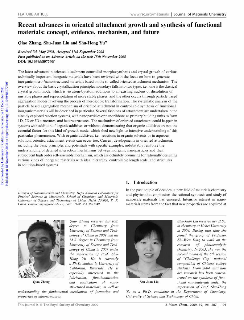
Recent advances in oriented attachment growth and synthesis of functionalmaterials: concept, evidence, mechanism, and future
Qiao Zhang, Shu-Juan Liu and Shu-Hong Yu*
Received 7th May 2008, Accepted 17th September 2008
First published as an Advance Article on the web 18th November 2008
DOI: 10.1039/b807760f
The latest advances in oriented attachment controlled morphosynthesis and crystal growth of various
technically important inorganic materials have been reviewed with the focus on how to generate
inorganic micro-/nanostructured materials based on the so-called oriented attachment mechanism. The
overview about the basic crystallization principles nowadays falls into two types, i.e., one is the classical
crystal growth mode, which is via atom-by-atom additions to an existing nucleus or dissolution of
unstable phases and reprecipitation of more stable phases, and the other occurs through particle based
aggregation modes involving the process of mesoscopic transformation. The systematic analysis of the
particle based aggregation mechanism of oriented attachment in controllable synthesis of functional
inorganic materials will be described in particular. Several fashions of attachment are undertaken in the
already explored reaction systems, with nanoparticles or nanoribbons as primary building units to form
1D, 2D or 3D structures, and heterostructures. The mechanism of oriented attachment could happen in
systems with addition of organic additives or without, demonstrating that organic additives are not the
essential factor for this kind of growth mode, which shed new light to intensive understanding of this
particular phenomenon. With organic additives, i.e., reactions in organic solvents or in aqueous
solution, oriented attachment events can occur too. Current developments in oriented attachment,
including the basic principles and potentials with specific examples, indubitably reinforce the
understanding of detailed interaction mechanisms between inorganic nanoparticles and their
subsequent high order self-assembly mechanism, which are definitely promising for rationally designing
various kinds of inorganic materials with ideal hierarchy, controllable length scale, and structures
in solution-based systems.
Qiao Zhang
Qiao Zhang received his B.S.
degree in Chemistry from
University of Science and Tech-
nology of China in 2004 and his
M.S. degree in Chemistry from
University of Science and Tech-
nology of China in 2007 under
the supervision of Prof. Shu-
Hong Yu. He is currently
a Ph.D. student in University of
California, Riverside. He is
especially interested in the
fabrication, functionalization
and application of nano-
structured materials, as well as
understanding the fundamental mechanism of formation and
properties of nanostructures.
Division of Nanomaterials and Chemistry, Hefei National Laboratory forPhysical Sciences at Microscale, School of Chemistry and Materials,University of Science and Technology of China, Hefei, 230026, P. R.China. E-mail: [email protected]; Fax: +0086 551 3603040
This journal is ª The Royal Society of Chemistry 2009
1. Introduction
In the past couple of decades, a new field of materials chemistry
and physics that emphasizes the rational synthesis and study of
nanoscale materials has emerged. Intensive interest in nano-
materials stems from the fact that new properties are acquired at
Shu-Juan Liu
Shu-Juan Liu received her B.Sc.
in chemistry at Hebei University
in 2004. During that time she
joined the group of Professor
Shi-Wen Ding to work on the
research of photocatalytic
chemistry. In 2003, she won the
second award of the 8th session
of ‘‘Challenge Cup’’ national
competition of Chinese college
students. From 2004 until now
her research has been concen-
trated on the synthesis of func-
tional nanomaterials under the
supervision of Prof. Shu-Hong
Yu as a Ph.D. candidate in the Department of Chemistry,
University of Science and Technology of China.
J. Mater. Chem., 2009, 19, 191–207 | 191
Dow
nloa
ded
by U
nive
rsity
of
Cal
ifor
nia
- R
iver
side
on
15 D
ecem
ber
2011
Publ
ishe
d on
18
Nov
embe
r 20
08 o
n ht
tp://
pubs
.rsc
.org
| do
i:10.
1039
/B80
7760
F
View Online
this length scale and, equally important, that these properties
change with their sizes or shapes.1 Therefore, tailoring the
shapes, sizes and properties of nanostructures is one of the major
challenges that must be achieved from the viewpoint of appli-
cations in nanotechnology. In the past, controlled preparation of
nanocrystals with specific sizes and shape has been extensively
investigated in studies involving the synthesis of nanoparticles2–11
and searching for suitable methods for growing anisotropic
crystals such as nanowires,12,13 nanoribbons and nanorods,14–16
and others.17–19 However, this is still a very active field strongly
motivated by the preparation of nanostructures with tailored
morphologies and thus tailored properties using nanoparticles as
building blocks.
Solution-based procedures for the preparation of nano-
structures (a ‘‘bottom-up’’ approach) are considered very
promising because of their potential to allow for precise control
over the morphology and sizes of nanoparticles and thus tune
their properties. Although crystallization from a solution is such
a familiar process that it is likely thought to be fully understood,
many key problems are still unsolved in spite of a large amount
of research on it.20
As accepted for about 100 years, the ‘‘Ostwald ripening
process’’ is usually used to explain how a crystal comes into
being.21 For example, many efforts have been focused on
anisotropic growth in various systems in which particle coars-
ening can be well explained by the Ostwald ripening mecha-
nism,22–25 such as ZnO,26,27 and TiO2.27,28 These systems are
characterized by significant solubility of the crystals in the liquid
medium, which allows for surface diffusion and generally results
in spherical particles. However, intense research on coarsening
behavior and morphology evolution of nanomaterials shows that
the Ostwald ripening mechanism cannot explain all phenomena
well. For instance, some studies have demonstrated the possi-
bility of fostering anisotropic growth in these systems by main-
taining the solute concentration higher than the equilibrium
concentration.6,15,29 Peng et al.7 also stated that the supersatu-
ration state in solution prevents the smaller particles from being
dissolved, and growth occurs by precipitation of dissolved ions in
high-energy facets instead of coarsening.
On the other hand, Penn and Banfield presented a new crystal
growth mechanism, the so-called ‘‘oriented attachment’’ mecha-
nism, in which secondary mono-crystalline particles can be
Shu-Hong Yu
Shu-Hong Yu was born in 1967. He r
Science and Technology of China un
joined Prof. Masahiro Yoshimura’s
Technology, as a JSPS Research Fe
Research Fellow in the Max Planck
with PD Dr habil. Helmut C€olfen and
in 2002 and the Cheung Kong Prof
Science and Technology of China (U
Chemistry, Hefei National Laborat
interests include bio-inspired synthes
carbon related materials, and their r
refereed journal publications, and 8
national journal Materials Research
192 | J. Mater. Chem., 2009, 19, 191–207
obtained through attachments of primary particles in an irre-
versible and highly oriented fashion.30–34 This process seems very
promising as a route for the preparation of complex-shaped
nanostructures using primary nanoparticles themselves as
building blocks, which has been reported previously in the role of
‘‘oriented attachment’’ in anisotropic growth of nano-
crystals,12,30–36 such as a-Fe2O3,37,38 Fe3O4,
39 PAu,40 hydroxyap-
atite (Ca10(PO4)6(OH)2),41CdTe, PbSe,42 SnO2,
16,43 TiO2,44,45 and
ZnS.46,47 In these systems, the bigger particles are grown from
small primary nanoparticles through an oriented attachment
mechanism, in which the adjacent nanoparticles are self-assem-
bled by sharing a common crystallographic orientation and
docking of these particles at a planar interface. The driving force
for this spontaneous oriented attachment is that the elimination
of the pairs of high energy surfaces will lead to a substantial
reduction in the surface free energy from the thermodynamic
viewpoint.33,48 In this Feature Article, recent advances in this
special emerging field will be reviewed. We start with a discussion
of basic theories and general views in crystal growth in Section 2.
Then, in Section 3, concepts and development of oriented
attachment mechanism will be discussed, and some selected
examples will be presented to highlight the importance and
versatility of this new crystal growth mechanism for materials
science on the way to the development of new strategies for
shaping crystals and morphogenesis, and hence, their related
properties.
2. Crystal growth modes and aggregation modes
2.1 Classical crystal growth mode
Classically, growth of crystals has been thought to occur by
atom-by-atom or monomer-by-monomer addition to an inor-
ganic or organic template or by dissolution of unstable phases
(small particles or metastable polymorphs) and reprecipitation
of the more stable phase.49 Thus, the chemical growth of bulk
or nanometer-sized materials inevitably involves the process of
precipitation of a solid phase from solution. A good under-
standing of the process and parameters controlling the precipi-
tation helps to improve the engineering of the growth of
nanoparticles to the desired size and shape. For a particular
solvent, there is a certain solubility for a solute, whereby addition
eceived his PhD in Inorganic Chemistry in 1998 from University of
der the supervision of Prof. Yi-Tai Qian. From 1999 to 2001, he
Lab in Materials and Structures Laboratory, Tokyo Institute of
llow. From 2001 to 2002, he was as an Alexander von Humboldt
Institute of Colloids and Interfaces, Potsdam, Germany, working
Prof. Dr Markus Antonietti. He was appointed as a full professor
essorship in 2006 in the Department of Chemistry, University of
STC). Currently, he is leading the Division of Nanomaterials &
ory for Physical Sciences at Microscale (HFNL). His research
is and self-assembly of new nanostructured materials and hybrids,
elated properties. He has authored and co-authored more than 150
invited book chapters. He serves as an associate editor for inter-
Bulletin, and is a board member of journal Current Nanoscience.
This journal is ª The Royal Society of Chemistry 2009
Dow
nloa
ded
by U
nive
rsity
of
Cal
ifor
nia
- R
iver
side
on
15 D
ecem
ber
2011
Publ
ishe
d on
18
Nov
embe
r 20
08 o
n ht
tp://
pubs
.rsc
.org
| do
i:10.
1039
/B80
7760
F
View Online
of any excess solute will result in precipitation and formation of
nanocrystals. Thus, in the case of nanoparticle formation, for
nucleation to occur, the solution must be supersaturated either
by directly dissolving the solute at higher temperature and then
cooling to low temperatures, or by adding the necessary reactants
to produce a supersaturated solution during the reaction.6,50 The
precipitation process then basically consists of a nucleation
step followed by particle growth stages.51,52
Generally, there are three kinds of nucleation processes:
homogeneous nucleation, heterogeneous nucleation, and
secondary nucleation. We consider the simplest case of homo-
geneous nucleation, which occurs in the absence of a solid
interface by combining solute molecules to produce nuclei.
Homogeneous nucleation happens due to the driving force of the
thermodynamics because the supersaturated solution is not
stable in energy. The overall free energy change,DG, is the sum of
the free energy due to the formation of a new volume and the free
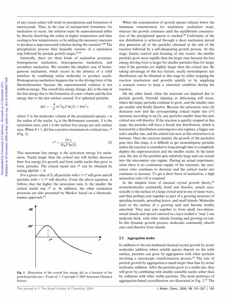
energy due to the new surface created. For spherical particles
DG ¼ � 4
Vpr3kBT lnðSÞ þ 4pr2g (1)
where V is the molecular volume of the precipitated species, r is
the radius of the nuclei, kB is the Boltzmann constant, S is the
saturation ratio, and g is the surface free energy per unit surface
area.When S > 1,DG has a positive maximum at a critical size, r*
(Fig. 1).
r* ¼ 2Vg
3kBT lnðSÞ (2)
This maximum free energy is the activation energy for nucle-
ation. Nuclei larger than the critical size will further decrease
their free energy for growth and form stable nuclei that grow to
form particles. The critical nuclei size r* can be obtained by
setting dDG/dr ¼ 0.
For a given value of S, all particles with r > r* will grow and all
particles with r < r* will dissolve. From the above equation, it
follows that the higher the saturation ratio S, the smaller the
critical nuclei size r* is. In addition, the other nucleation
processes are also presented by Markov based on a thermody-
namics approach.53
Fig. 1 Illustration of the overall free energy DG as a function of the
growth particle size r. From ref. 1. Copyrightª 2005 American Chemical
Society.
This journal is ª The Royal Society of Chemistry 2009
When the concentration of growth species reduces below the
minimum concentration for nucleation, nucleation stops,
whereas the growth continues until the equilibrium concentra-
tion of the precipitated species is reached.54 Uniformity of the
size distribution is achieved through a short nucleation period
that generates all of the particles obtained at the end of the
reaction followed by a self-sharpening growth process. At this
stage, kinetic control and focusing of size occurs: the smaller
particles grow more rapidly than the larger ones because the free
energy driving force is larger for smaller particles than for larger
ones if the particles are slightly larger than the critical size. By
taking advantage of this key feature, nearly monodisperse size
distribution can be obtained at this stage by either stopping the
reaction (nucleation and growth) quickly or by supplying
a reactant source to keep a saturated condition during the
reaction.
On the other hand, when the reactants are depleted due to
particle growth, Ostwald ripening or defocusing will occur,
where the larger particles continue to grow, and the smaller ones
get smaller and finally dissolve. Because the saturation ratio (S)
decreases now and the corresponding critical nuclei size (r*)
increases according to eq (2), any particles smaller than this new
critical size will dissolve. If the reaction is quickly stopped at this
stage, the particles will have a broad size distribution, which is
featured by a distribution centering two size regimes, a bigger one
and a smaller one, and the critical size now at this saturation is in
between. Once the reaction (mainly the growth of the particles)
goes into this stage, it is difficult to get monodisperse particles
unless the reaction is extended to long enough time to completely
deplete the supersaturation and the smaller nuclei. In the latter
case, the size of the particles gets relatively large and can extend
into the micrometer size regime. During an actual experiment,
when there is no continuous supply of the reactants, the satu-
ration ratio continues to decrease and the critical nuclei size
continues to increase. To get a short burst of nucleation, a high
saturation ratio (S) is required.
In the simplest form of classical crystal growth theory,55
atoms/molecules continually bond and dissolve, attach occa-
sionally to the surface of a large crystal seed in one of many ways,
and then perhaps join together as part of a growing structure of
spiraling mounds, spreading layers, and small islands. Molecules
land on the surface of a growing seed and become weakly
adsorbed. They may join together to form small, two-dimen-
sional islands and spread outward in a layer (called a ‘‘step’’) one
molecule thick, with other islands forming and growing on top.
In this dynamic growth process, molecules continually absorb
onto and dissolve from islands.
2.2 Aggregation modes
In addition to the ion-mediated classical crystal growth by atom/
molecular addition where soluble species deposit on the solid
surface, particles can grow by aggregation with other particles
involving a mesoscopic transformation process.56 The rate of
particle growth by aggregation is much larger than that by atom/
molecular addition. After the particles grow to a stable size, they
will grow by combining with smaller unstable nuclei rather than
by collisions with other stable particles. The main pathways of
aggregation-based crystallization are illustrated in Fig. 2.57 The
J. Mater. Chem., 2009, 19, 191–207 | 193

Fig. 2 Schematic representation of classical and aggregation-based
crystallization. (Left) Classical crystallization pathway (a), (centre)
oriented attachment of primary nanoparticles forming an iso-oriented
crystal upon fusing (path (b)), (right) mesocrystal formation via self-
assembly of primary nanoparticles covered with organics (path (c)).
From ref. 57. Copyright ª 2005 Wiley-VCH.
Fig. 3 (a) TEM micrograph of hydrothermally coarsened anatase
particles forming a chain-like nanostructure, (b) HRTEM of a part of
such an assembly proving the single crystalline nature. From ref. 32.
Copyright ª 1999 Elsevier Sciences.
Dow
nloa
ded
by U
nive
rsity
of
Cal
ifor
nia
- R
iver
side
on
15 D
ecem
ber
2011
Publ
ishe
d on
18
Nov
embe
r 20
08 o
n ht
tp://
pubs
.rsc
.org
| do
i:10.
1039
/B80
7760
F
View Online
classical crystal growth model is described by path (a). Path (b)
involves the arrangement of primary nanoparticles into an iso-
oriented crystal via oriented attachment, which can form a single
crystal upon fusion of the nanoparticles. If the nanoparticles
are coated by some organic components, they can form a meso-
crystal via mesoscale assembly (path (c)), possibly followed by
fusion to an iso-oriented crystal and finally to a single crystal.58–61
To the best of our knowledge, more and more mesocrystals built
from three-dimensional (3D) and well-aligned crystals while
exhibiting scattering properties similar to a single crystal have
been observed, such as CdS,62 CoC2O4$2H2O,63 CaCO3,64–72
BaCO3,73 D,L-alanine,57,74 CoPt3,
75 ZnO-PVP nanocomposites,76
even Au77 and Ag.78
Nanoparticles are small and are not thermodynamically stable
for crystal growth kinetically. To finally produce stable nano-
particles, these nanoparticles must be arrested during the reac-
tion either by adding surface protecting reagents, such as organic
ligands or inorganic capping materials, or by placing them in an
inert environment such as an inorganic matrix or polymer. The
nanocrystal (NC) dispersions are stable if the interaction between
the capping groups and the solvent is favorable, providing an
energetic barrier to counteract the van der Waals and magnetic
attractions (magnetic materials) between nanoparticles.79 To
help arrest these nanoparticles, different solvents are also used
to change the solubility or the reaction rate.50,52
Aggregation-based crystallization offers some peculiar
advantages with respect to crystal morphogenesis such as the
near independence of solubility products and indifference to pH
and osmotic pressure. These features are particularly relevant in
biological systems and accordingly the study of non-classical
crystallization processes is documented for biomineralization.
Recently, the investigation of the role of amorphous precursor
particles has attracted a lot of attention,56,80–86 rather than the
investigation of oriented attachment or mesocrystal forma-
tion.87–89 However, a look into recent literature clearly reveals
that these new crystallization routes will also play a vital role in
materials science, for example, in the synthesis of advanced
functional materials.
194 | J. Mater. Chem., 2009, 19, 191–207
3. Oriented attachment growth: new mechanism
Traditional solution synthesis methods have been widely used for
the controlled synthesis of various colloidal nanoparticles.95,96
Classically, crystal coarsening has been described in terms of
growth of large particles at the expense of smaller particles.97 The
driving force for this so-called Ostwald ripening process is the
surface energy reduction. In this process, the formation of tiny
crystalline nuclei in a supersaturated medium occurs first and
then is followed by crystal growth, in which the larger particles
will grow at the cost of the small ones due to the energy difference
between large particles and the smaller particles of a higher
solubility based on the Gibbs–Thompson law.98
While in these systems the bigger particles are grown from
small primary nanoparticles through an oriented attachment
mechanism, the adjacent nanoparticles are self-assembled by
sharing a common crystallographic orientation and docking of
these particles at a planar interface. The driving force for this
spontaneous oriented attachment is that the elimination of
the pairs of high energy surfaces will lead to a substantial
reduction in the surface free energy from the thermodynamic
viewpoint.
Averback et al. identified a similar spontaneous self-assembly
process which they called ‘‘contact epitaxy’’ during their study of
the deposition of Ag nanoparticles onto Cu substrates.99,100 The
initial randomly oriented Ag nanocrystals can align epitaxially
with the substrate, which was explained as the rotation of the
nanoparticles within the aggregates driven by short-range inter-
actions between adjacent surfaces.99 Increasing evidence in
several systems has been observed for either directed particle
aggregation or undirected particle aggregation. This kind of
growth mode could lead to the formation of faceted particles or
anisotropic growth if it occurs near equilibrium and there is
sufficient difference in the surface energies of different crystal-
lographic faces. It is possible to form perfect highly anisotropic
crystals, which clearly show the growth via oriented attachment
as impressively evidenced for TiO2.32
In 1999, Penn and Banfield32 reported that in the case of
hydrothermally coarsened anatase TiO2, the nanoparticles
assemble into single crystalline structures composed of several
primary crystallites (Fig. 3). The crystallographic orientation of
the particles with respect to each other is determined by the
minimization of the highest energy surfaces. When two nano-
particles approach each other closely enough, they are mutually
attracted by van der Waals forces. However, due to their thermal
energy, they can still rearrange to find the low-energy configura-
tion represented by a coherent particle–particle interface.33,101–103
There are a few studies emerging recently, which deal with the
kinetics of the oriented aggregation by Penn,101Leite et al.,102 and
This journal is ª The Royal Society of Chemistry 2009

Fig. 4 TEM image showing a-Fe2O3 double-ellipsoids produced by
aging a solution (0.018 M FeCl3, 0.05 M HCl) at 100 �C for one week.
From ref. 37. Copyright ª 1993 Elsevier Sciences.
Fig. 5 Classical (a) vs. non-classical crystallization (b, c). (a) Crystalli-
zation of hydroxyapatite (HAP) fibres from block copolymer aggre-
gates,90 where the block copolymers adsorb to all faces parallel to the
HAP c-growth axis resulting in whisker structures with occasional
branches (d, see arrows). (b, c, e) Formation of single crystalline and
defect-free BaSO4 (210) oriented fiber bundles by oriented attachment
process in experiments described in ref. 91–93. From ref. 94. CopyrightªEditorial Universitaria.
Dow
nloa
ded
by U
nive
rsity
of
Cal
ifor
nia
- R
iver
side
on
15 D
ecem
ber
2011
Publ
ishe
d on
18
Nov
embe
r 20
08 o
n ht
tp://
pubs
.rsc
.org
| do
i:10.
1039
/B80
7760
F
View Online
the mathematical models for crystal growth through aggregation
of metastable precursor nanoparticles by Tsapatsis et al.103
An early interesting finding by Bailey et al.37 shows that
a rather complex morphology of a-Fe2O3 double-ellipsoids
(Fig. 4) can be easily obtained through aging a solution con-
taining b-FeOOH rods at 100 �C for one week which was
obtained by a hydrolysis reaction of FeCl3 in HCl solution. These
complex double-ellipsoid structures were clearly developed from
the heterogeneous nucleation of hematite on b-FeOOH rods
formed in the early stage. The a-Fe2O3 (hematite) particles not
only grow outward but also use these rods as templates and
a collar forms along the rods, leading to the formation of such
double-ellipsoid shapes. This example shows that the size and
aggregation of the metastable phase can influence the final
morphology.
Oriented attachment offers the special advantage of producing
defect-free one-dimensional single crystals, which is certainly of
interest in materials science. Classical crystallization always
causes defect structures in the form of branches when attempting
fibre growth by additive adsorption to all crystal faces parallel to
the growth axis and thus these faces become blocked from
further growth. In contrast, oriented attachment offers the
crystallographic fusion of nanoparticles to single crystalline and
defect-free fibres, which can be hundreds of micrometers long.
This is demonstrated in the example of hydroxyapatite (HAP)
fibres (Fig. 5a), whose aggregates of special block copolymers
were adsorbed to all faces parallel to the c-growth axis.94
Although thin and long crystalline HAP fibres were obtained
(the single crystalline nature of the fibres could not be shown due
to their small diameter of only 2–3 nm), the fibres clearly show
occasional branches (Fig. 5a, d). These can be attributed to
a noncontinuous polymer layer, so that branching can occur at
the non-covered sites on the crystal as result of the ion-based
classical growth mechanism. On the other hand, if all crystal
This journal is ª The Royal Society of Chemistry 2009
faces parallel to one axis of a nanoparticle are already covered by
polymers, only two opposite faces remain uncovered and thus
become high energy faces. These faces can then fuse together to
form a single crystalline fibre without any defects following
the mechanism of oriented attachment (Fig. 5b, c). Here, the
advantages of the particle-based mechanism compared to the
ion-based one become directly obvious.
It has to be pointed that the oriented attachment is not only
described for the one-dimensional case, but is also described
for two- and three- dimensional cases.104 In addition, when
combined with other synthesis methods, oriented attachment
mechanism could also be used to organize hierarchical structures
in three dimensions with or without hollow interiors, which has
been expatiated in a review by Zeng.105
3.1 Oriented attachment growth in the presence of organic
additives
The shape of a crystal is determined by the relative specific
surface energies associated with the facets of this crystal. At
equilibrium, a crystal has to be bounded by facets giving
a minimum total surface energy, an argument that is known as
the Wulff facets theorem.106 Confined by this requirement, the
shape of a single crystalline nanostructure often reflects the
intrinsic symmetry of the corresponding lattice (for most metals,
it is a cube rather than a rod).107–113 The shape of a crystal can
also be considered in terms of growth kinetics, by which the
fastest growing planes should disappear to leave behind the
slowest growing planes as the facets of the product.114,115 This
argument implies that one can control the final shape of a crystal
by introducing appropriate organic molecules to change the free
energies to alter their growth rates, and hence, in order to control
their size, shape and even structure.116,117 In the past, a range
of compounds have been evaluated as capping reagents (or
so-called surface-modifiers) to control the shape of colloidal
J. Mater. Chem., 2009, 19, 191–207 | 195
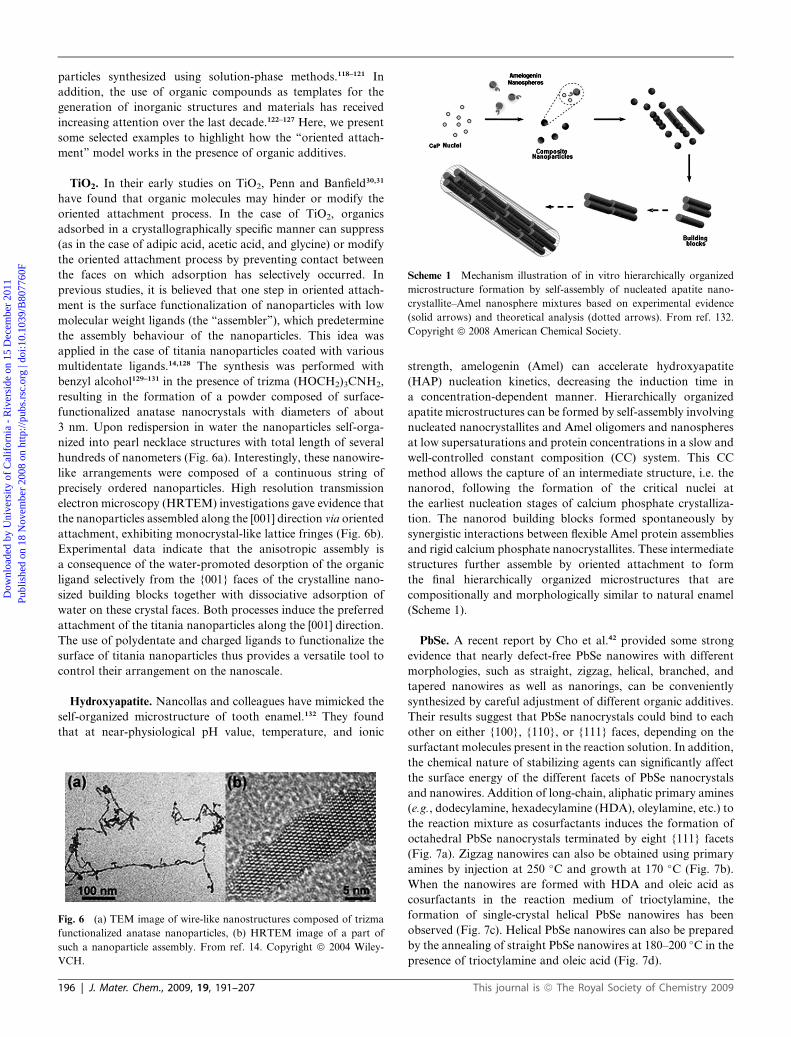
Scheme 1 Mechanism illustration of in vitro hierarchically organized
microstructure formation by self-assembly of nucleated apatite nano-
crystallite–Amel nanosphere mixtures based on experimental evidence
(solid arrows) and theoretical analysis (dotted arrows). From ref. 132.
Copyright ª 2008 American Chemical Society.
Dow
nloa
ded
by U
nive
rsity
of
Cal
ifor
nia
- R
iver
side
on
15 D
ecem
ber
2011
Publ
ishe
d on
18
Nov
embe
r 20
08 o
n ht
tp://
pubs
.rsc
.org
| do
i:10.
1039
/B80
7760
F
View Online
particles synthesized using solution-phase methods.118–121 In
addition, the use of organic compounds as templates for the
generation of inorganic structures and materials has received
increasing attention over the last decade.122–127 Here, we present
some selected examples to highlight how the ‘‘oriented attach-
ment’’ model works in the presence of organic additives.
TiO2. In their early studies on TiO2, Penn and Banfield30,31
have found that organic molecules may hinder or modify the
oriented attachment process. In the case of TiO2, organics
adsorbed in a crystallographically specific manner can suppress
(as in the case of adipic acid, acetic acid, and glycine) or modify
the oriented attachment process by preventing contact between
the faces on which adsorption has selectively occurred. In
previous studies, it is believed that one step in oriented attach-
ment is the surface functionalization of nanoparticles with low
molecular weight ligands (the ‘‘assembler’’), which predetermine
the assembly behaviour of the nanoparticles. This idea was
applied in the case of titania nanoparticles coated with various
multidentate ligands.14,128 The synthesis was performed with
benzyl alcohol129–131 in the presence of trizma (HOCH2)3CNH2,
resulting in the formation of a powder composed of surface-
functionalized anatase nanocrystals with diameters of about
3 nm. Upon redispersion in water the nanoparticles self-orga-
nized into pearl necklace structures with total length of several
hundreds of nanometers (Fig. 6a). Interestingly, these nanowire-
like arrangements were composed of a continuous string of
precisely ordered nanoparticles. High resolution transmission
electron microscopy (HRTEM) investigations gave evidence that
the nanoparticles assembled along the [001] direction via oriented
attachment, exhibiting monocrystal-like lattice fringes (Fig. 6b).
Experimental data indicate that the anisotropic assembly is
a consequence of the water-promoted desorption of the organic
ligand selectively from the {001} faces of the crystalline nano-
sized building blocks together with dissociative adsorption of
water on these crystal faces. Both processes induce the preferred
attachment of the titania nanoparticles along the [001] direction.
The use of polydentate and charged ligands to functionalize the
surface of titania nanoparticles thus provides a versatile tool to
control their arrangement on the nanoscale.
Hydroxyapatite. Nancollas and colleagues have mimicked the
self-organized microstructure of tooth enamel.132 They found
that at near-physiological pH value, temperature, and ionic
Fig. 6 (a) TEM image of wire-like nanostructures composed of trizma
functionalized anatase nanoparticles, (b) HRTEM image of a part of
such a nanoparticle assembly. From ref. 14. Copyright ª 2004 Wiley-
VCH.
196 | J. Mater. Chem., 2009, 19, 191–207
strength, amelogenin (Amel) can accelerate hydroxyapatite
(HAP) nucleation kinetics, decreasing the induction time in
a concentration-dependent manner. Hierarchically organized
apatite microstructures can be formed by self-assembly involving
nucleated nanocrystallites and Amel oligomers and nanospheres
at low supersaturations and protein concentrations in a slow and
well-controlled constant composition (CC) system. This CC
method allows the capture of an intermediate structure, i.e. the
nanorod, following the formation of the critical nuclei at
the earliest nucleation stages of calcium phosphate crystalliza-
tion. The nanorod building blocks formed spontaneously by
synergistic interactions between flexible Amel protein assemblies
and rigid calcium phosphate nanocrystallites. These intermediate
structures further assemble by oriented attachment to form
the final hierarchically organized microstructures that are
compositionally and morphologically similar to natural enamel
(Scheme 1).
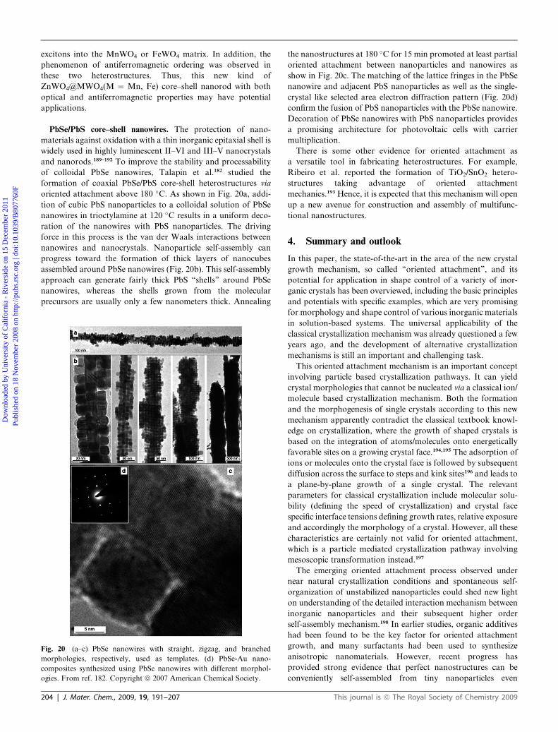
PbSe. A recent report by Cho et al.42 provided some strong
evidence that nearly defect-free PbSe nanowires with different
morphologies, such as straight, zigzag, helical, branched, and
tapered nanowires as well as nanorings, can be conveniently
synthesized by careful adjustment of different organic additives.
Their results suggest that PbSe nanocrystals could bind to each
other on either {100}, {110}, or {111} faces, depending on the
surfactant molecules present in the reaction solution. In addition,
the chemical nature of stabilizing agents can significantly affect
the surface energy of the different facets of PbSe nanocrystals
and nanowires. Addition of long-chain, aliphatic primary amines
(e.g., dodecylamine, hexadecylamine (HDA), oleylamine, etc.) to
the reaction mixture as cosurfactants induces the formation of
octahedral PbSe nanocrystals terminated by eight {111} facets
(Fig. 7a). Zigzag nanowires can also be obtained using primary
amines by injection at 250 �C and growth at 170 �C (Fig. 7b).
When the nanowires are formed with HDA and oleic acid as
cosurfactants in the reaction medium of trioctylamine, the
formation of single-crystal helical PbSe nanowires has been
observed (Fig. 7c). Helical PbSe nanowires can also be prepared
by the annealing of straight PbSe nanowires at 180–200 �C in the
presence of trioctylamine and oleic acid (Fig. 7d).
This journal is ª The Royal Society of Chemistry 2009
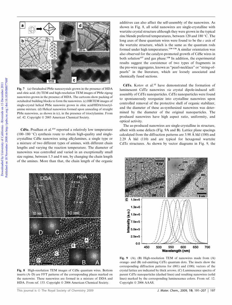
Fig. 7 (a) Octahedral PbSe nanocrystals grown in the presence of HDA
and oleic acid. (b) TEM and high-resolution TEM images of PbSe zigzag
nanowires grown in the presence of HDA. The cartoons show packing of
octahedral building blocks to form the nanowires. (c) HRTEM images of
single-crystal helical PbSe nanowire grown in oleic acid/HDA/trioctyl-
amine mixture. (d) Helical nanowires formed upon annealing of straight
PbSe nanowires, as shown in (c), in the presence of trioctylamine. From
ref. 42. Copyright ª 2005 American Chemical Society.
Dow
nloa
ded
by U
nive
rsity
of
Cal
ifor
nia
- R
iver
side
on
15 D
ecem
ber
2011
Publ
ishe
d on
18
Nov
embe
r 20
08 o
n ht
tp://
pubs
.rsc
.org
| do
i:10.
1039
/B80
7760
F
View Online
CdSe. Pradhan et al.133 reported a relatively low temperature
(100–180 �C) synthesis route to obtain high-quality and single-
crystalline CdSe nanowires using alkylamines, a single type or
a mixture of two different types of amines, with different chain
lengths and varying the reaction temperature. The diameter of
nanowires was controlled and varied in an exceptionally small
size regime, between 1.5 and 6 nm, by changing the chain length
of the amines. More than that, the chain length of the organic
Fig. 8 High-resolution TEM images of CdSe quantum wires. Bottom
inserts (A–D) are FFT patterns of the corresponding places marked on
the nanowire. These nanowires are formed in a mixture of DDA and
HDA. From ref. 133. Copyright ª 2006 American Chemical Society.
This journal is ª The Royal Society of Chemistry 2009
additives can also affect the self-assembly of the nanowires. As
shown in Fig. 8, all solid nanowires are single-crystalline with
wurtzite crystal structure although they were grown in the typical
zinc blende preferred temperatures, between 120 and 180 �C. The
long axes of these quantum wires were found to be the c axis of
the wurtzite structure, which is the same as the quantum rods
formed under high temperatures.134–136 A similar orientation was
also observed for the catalyst-promoted growth of CdSe wires in
both solution137 and gas phase.138 In addition, the experimental
results suggest the coexistence of two types of fragments in
the pre-wire aggregates, known as ‘‘pearl-necklace’’ or ‘‘string-of-
pearls’’ in the literature, which are loosely associated and
chemically fused sections.
CdTe. Kotov et al.12 have demonstrated the formation of
luminescent CdTe nanowires via crystal dipole-induced self-
assembly of CdTe nanoparticles. CdTe nanoparticles were found
to spontaneously reorganize into crystalline nanowires upon
controlled removal of the protective shell of organic stabilizer,
and the diameter of these as-synthesized nanowires was deter-
mined by the diameter of the original nanoparticles. The
produced nanowires have high aspect ratio, uniformity, and
optical activity.
The as-produced nanowires are single-crystalline in structure,
albeit with some defects (Fig. 9A and B). Lattice plane spacings
calculated from the diffraction patterns are 3.98 A hkl (100) and
2.29 A hkl (110) and are typical for hexagonal wurtzite
CdTe structures. As shown by vector diagrams in Fig. 9, the
Fig. 9 (A), (B) High-resolution TEM of nanowires made from (A)
orange- and (B) red-emitting CdTe quantum dots. The insets show the
corresponding diffraction patterns for (001) and (100); vectors of the
crystal lattice are indicated by thick arrows. (C) Luminescence spectra of
parent CdTe nanoparticles (dashed lines) and resulting nanowires (solid
lines) marked by the corresponding luminescence colors. From ref. 12.
Copyright ª 2006 AAAS.
J. Mater. Chem., 2009, 19, 191–207 | 197
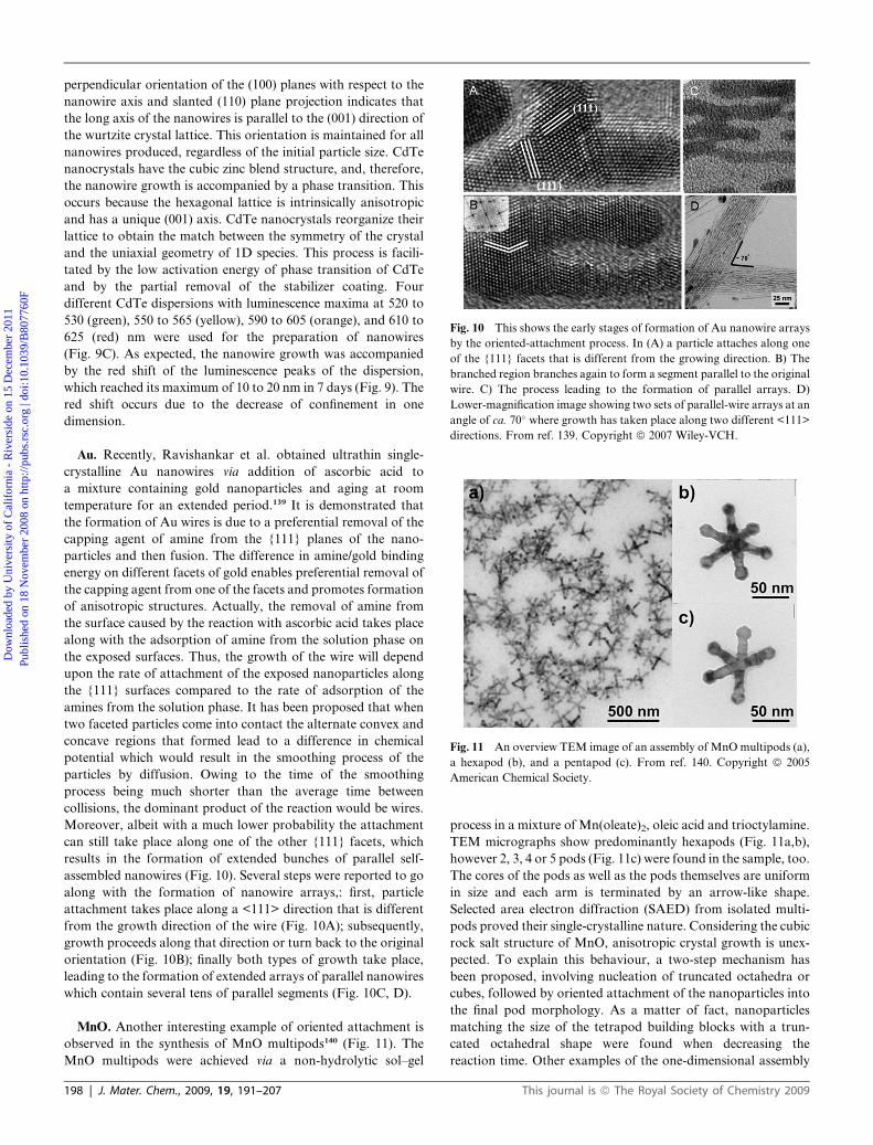
Fig. 10 This shows the early stages of formation of Au nanowire arrays
by the oriented-attachment process. In (A) a particle attaches along one
of the {111} facets that is different from the growing direction. B) The
branched region branches again to form a segment parallel to the original
wire. C) The process leading to the formation of parallel arrays. D)
Lower-magnification image showing two sets of parallel-wire arrays at an
angle of ca. 70� where growth has taken place along two different <111>
directions. From ref. 139. Copyright ª 2007 Wiley-VCH.
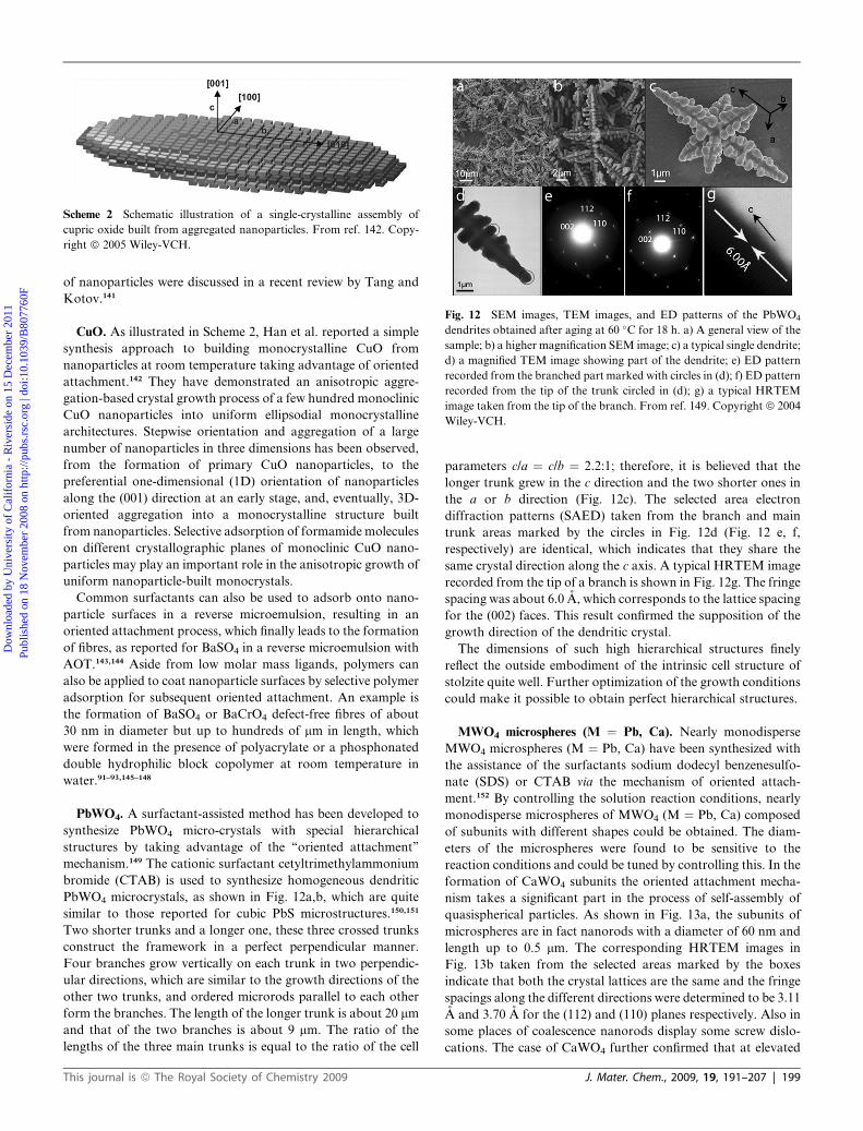
Fig. 11 An overview TEM image of an assembly of MnOmultipods (a),
a hexapod (b), and a pentapod (c). From ref. 140. Copyright ª 2005
American Chemical Society.
Dow
nloa
ded
by U
nive
rsity
of
Cal
ifor
nia
- R
iver
side
on
15 D
ecem
ber
2011
Publ
ishe
d on
18
Nov
embe
r 20
08 o
n ht
tp://
pubs
.rsc
.org
| do
i:10.
1039
/B80
7760
F
View Online
perpendicular orientation of the (100) planes with respect to the
nanowire axis and slanted (110) plane projection indicates that
the long axis of the nanowires is parallel to the (001) direction of
the wurtzite crystal lattice. This orientation is maintained for all
nanowires produced, regardless of the initial particle size. CdTe
nanocrystals have the cubic zinc blend structure, and, therefore,
the nanowire growth is accompanied by a phase transition. This
occurs because the hexagonal lattice is intrinsically anisotropic
and has a unique (001) axis. CdTe nanocrystals reorganize their
lattice to obtain the match between the symmetry of the crystal
and the uniaxial geometry of 1D species. This process is facili-
tated by the low activation energy of phase transition of CdTe
and by the partial removal of the stabilizer coating. Four
different CdTe dispersions with luminescence maxima at 520 to
530 (green), 550 to 565 (yellow), 590 to 605 (orange), and 610 to
625 (red) nm were used for the preparation of nanowires
(Fig. 9C). As expected, the nanowire growth was accompanied
by the red shift of the luminescence peaks of the dispersion,
which reached its maximum of 10 to 20 nm in 7 days (Fig. 9). The
red shift occurs due to the decrease of confinement in one
dimension.
Au. Recently, Ravishankar et al. obtained ultrathin single-
crystalline Au nanowires via addition of ascorbic acid to
a mixture containing gold nanoparticles and aging at room
temperature for an extended period.139 It is demonstrated that
the formation of Au wires is due to a preferential removal of the
capping agent of amine from the {111} planes of the nano-
particles and then fusion. The difference in amine/gold binding
energy on different facets of gold enables preferential removal of
the capping agent from one of the facets and promotes formation
of anisotropic structures. Actually, the removal of amine from
the surface caused by the reaction with ascorbic acid takes place
along with the adsorption of amine from the solution phase on
the exposed surfaces. Thus, the growth of the wire will depend
upon the rate of attachment of the exposed nanoparticles along
the {111} surfaces compared to the rate of adsorption of the
amines from the solution phase. It has been proposed that when
two faceted particles come into contact the alternate convex and
concave regions that formed lead to a difference in chemical
potential which would result in the smoothing process of the
particles by diffusion. Owing to the time of the smoothing
process being much shorter than the average time between
collisions, the dominant product of the reaction would be wires.
Moreover, albeit with a much lower probability the attachment
can still take place along one of the other {111} facets, which
results in the formation of extended bunches of parallel self-
assembled nanowires (Fig. 10). Several steps were reported to go
along with the formation of nanowire arrays,: first, particle
attachment takes place along a <111> direction that is different
from the growth direction of the wire (Fig. 10A); subsequently,
growth proceeds along that direction or turn back to the original
orientation (Fig. 10B); finally both types of growth take place,
leading to the formation of extended arrays of parallel nanowires
which contain several tens of parallel segments (Fig. 10C, D).
MnO. Another interesting example of oriented attachment is
observed in the synthesis of MnO multipods140 (Fig. 11). The
MnO multipods were achieved via a non-hydrolytic sol–gel
198 | J. Mater. Chem., 2009, 19, 191–207
process in a mixture of Mn(oleate)2, oleic acid and trioctylamine.
TEM micrographs show predominantly hexapods (Fig. 11a,b),
however 2, 3, 4 or 5 pods (Fig. 11c) were found in the sample, too.
The cores of the pods as well as the pods themselves are uniform
in size and each arm is terminated by an arrow-like shape.
Selected area electron diffraction (SAED) from isolated multi-
pods proved their single-crystalline nature. Considering the cubic
rock salt structure of MnO, anisotropic crystal growth is unex-
pected. To explain this behaviour, a two-step mechanism has
been proposed, involving nucleation of truncated octahedra or
cubes, followed by oriented attachment of the nanoparticles into
the final pod morphology. As a matter of fact, nanoparticles
matching the size of the tetrapod building blocks with a trun-
cated octahedral shape were found when decreasing the
reaction time. Other examples of the one-dimensional assembly
This journal is ª The Royal Society of Chemistry 2009
Scheme 2 Schematic illustration of a single-crystalline assembly of
cupric oxide built from aggregated nanoparticles. From ref. 142. Copy-
right ª 2005 Wiley-VCH.
Fig. 12 SEM images, TEM images, and ED patterns of the PbWO4
dendrites obtained after aging at 60 �C for 18 h. a) A general view of the
sample; b) a higher magnification SEM image; c) a typical single dendrite;
d) a magnified TEM image showing part of the dendrite; e) ED pattern
recorded from the branched part marked with circles in (d); f) ED pattern
recorded from the tip of the trunk circled in (d); g) a typical HRTEM
image taken from the tip of the branch. From ref. 149. Copyright ª 2004
Wiley-VCH.
Dow
nloa
ded
by U
nive
rsity
of
Cal
ifor
nia
- R
iver
side
on
15 D
ecem
ber
2011
Publ
ishe
d on
18
Nov
embe
r 20
08 o
n ht
tp://
pubs
.rsc
.org
| do
i:10.
1039
/B80
7760
F
View Online
of nanoparticles were discussed in a recent review by Tang and
Kotov.141
CuO. As illustrated in Scheme 2, Han et al. reported a simple
synthesis approach to building monocrystalline CuO from
nanoparticles at room temperature taking advantage of oriented
attachment.142 They have demonstrated an anisotropic aggre-
gation-based crystal growth process of a few hundred monoclinic
CuO nanoparticles into uniform ellipsodial monocrystalline
architectures. Stepwise orientation and aggregation of a large
number of nanoparticles in three dimensions has been observed,
from the formation of primary CuO nanoparticles, to the
preferential one-dimensional (1D) orientation of nanoparticles
along the (001) direction at an early stage, and, eventually, 3D-
oriented aggregation into a monocrystalline structure built
from nanoparticles. Selective adsorption of formamide molecules
on different crystallographic planes of monoclinic CuO nano-
particles may play an important role in the anisotropic growth of
uniform nanoparticle-built monocrystals.
Common surfactants can also be used to adsorb onto nano-
particle surfaces in a reverse microemulsion, resulting in an
oriented attachment process, which finally leads to the formation
of fibres, as reported for BaSO4 in a reverse microemulsion with
AOT.143,144 Aside from low molar mass ligands, polymers can
also be applied to coat nanoparticle surfaces by selective polymer
adsorption for subsequent oriented attachment. An example is
the formation of BaSO4 or BaCrO4 defect-free fibres of about
30 nm in diameter but up to hundreds of mm in length, which
were formed in the presence of polyacrylate or a phosphonated
double hydrophilic block copolymer at room temperature in
water.91–93,145–148
PbWO4. A surfactant-assisted method has been developed to
synthesize PbWO4 micro-crystals with special hierarchical
structures by taking advantage of the ‘‘oriented attachment’’
mechanism.149 The cationic surfactant cetyltrimethylammonium
bromide (CTAB) is used to synthesize homogeneous dendritic
PbWO4 microcrystals, as shown in Fig. 12a,b, which are quite
similar to those reported for cubic PbS microstructures.150,151
Two shorter trunks and a longer one, these three crossed trunks
construct the framework in a perfect perpendicular manner.
Four branches grow vertically on each trunk in two perpendic-
ular directions, which are similar to the growth directions of the
other two trunks, and ordered microrods parallel to each other
form the branches. The length of the longer trunk is about 20 mm
and that of the two branches is about 9 mm. The ratio of the
lengths of the three main trunks is equal to the ratio of the cell
This journal is ª The Royal Society of Chemistry 2009
parameters c/a ¼ c/b ¼ 2.2:1; therefore, it is believed that the
longer trunk grew in the c direction and the two shorter ones in
the a or b direction (Fig. 12c). The selected area electron
diffraction patterns (SAED) taken from the branch and main
trunk areas marked by the circles in Fig. 12d (Fig. 12 e, f,
respectively) are identical, which indicates that they share the
same crystal direction along the c axis. A typical HRTEM image
recorded from the tip of a branch is shown in Fig. 12g. The fringe
spacing was about 6.0 A, which corresponds to the lattice spacing
for the (002) faces. This result confirmed the supposition of the
growth direction of the dendritic crystal.
The dimensions of such high hierarchical structures finely
reflect the outside embodiment of the intrinsic cell structure of
stolzite quite well. Further optimization of the growth conditions
could make it possible to obtain perfect hierarchical structures.
MWO4 microspheres (M ¼ Pb, Ca). Nearly monodisperse
MWO4 microspheres (M ¼ Pb, Ca) have been synthesized with
the assistance of the surfactants sodium dodecyl benzenesulfo-
nate (SDS) or CTAB via the mechanism of oriented attach-
ment.152 By controlling the solution reaction conditions, nearly
monodisperse microspheres of MWO4 (M ¼ Pb, Ca) composed
of subunits with different shapes could be obtained. The diam-
eters of the microspheres were found to be sensitive to the
reaction conditions and could be tuned by controlling this. In the
formation of CaWO4 subunits the oriented attachment mecha-
nism takes a significant part in the process of self-assembly of
quasispherical particles. As shown in Fig. 13a, the subunits of
microspheres are in fact nanorods with a diameter of 60 nm and
length up to 0.5 mm. The corresponding HRTEM images in
Fig. 13b taken from the selected areas marked by the boxes
indicate that both the crystal lattices are the same and the fringe
spacings along the different directions were determined to be 3.11
A and 3.70 A for the (112) and (110) planes respectively. Also in
some places of coalescence nanorods display some screw dislo-
cations. The case of CaWO4 further confirmed that at elevated
J. Mater. Chem., 2009, 19, 191–207 | 199
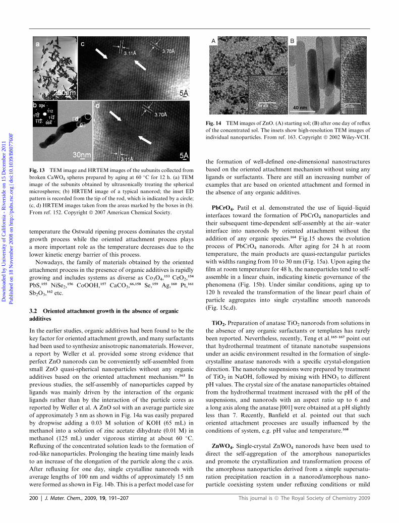
Fig. 13 TEM image and HRTEM images of the subunits collected from
broken CaWO4 spheres prepared by aging at 60 �C for 12 h. (a) TEM
image of the subunits obtained by ultrasonically treating the spherical
microspheres; (b) HRTEM image of a typical nanorod; the inset ED
pattern is recorded from the tip of the rod, which is indicated by a circle;
(c, d) HRTEM images taken from the areas marked by the boxes in (b).
From ref. 152. Copyright ª 2007 American Chemical Society.
Fig. 14 TEM images of ZnO. (A) starting sol; (B) after one day of reflux
of the concentrated sol. The insets show high-resolution TEM images of
individual nanoparticles. From ref. 163. Copyright ª 2002 Wiley-VCH.
Dow
nloa
ded
by U
nive
rsity
of
Cal
ifor
nia
- R
iver
side
on
15 D
ecem
ber
2011
Publ
ishe
d on
18
Nov
embe
r 20
08 o
n ht
tp://
pubs
.rsc
.org
| do
i:10.
1039
/B80
7760
F
View Online
temperature the Ostwald ripening process dominates the crystal
growth process while the oriented attachment process plays
a more important role as the temperature decreases due to the
lower kinetic energy barrier of this process.
Nowadays, the family of materials obtained by the oriented
attachment process in the presence of organic additives is rapidly
growing and includes systems as diverse as Co3O4,153 CeO2,
154
PbS,155 NiSe2,156 CoOOH,157 CaCO3,
66,158 Se,159 Ag,160 Pt,161
Sb2O3,162 etc.
3.2 Oriented attachment growth in the absence of organic
additives
In the earlier studies, organic additives had been found to be the
key factor for oriented attachment growth, and many surfactants
had been used to synthesize anisotropic nanomaterials. However,
a report by Weller et al. provided some strong evidence that
perfect ZnO nanorods can be conveniently self-assembled from
small ZnO quasi-spherical nanoparticles without any organic
additives based on the oriented attachment mechanism.163 In
previous studies, the self-assembly of nanoparticles capped by
ligands was mainly driven by the interaction of the organic
ligands rather than by the interaction of the particle cores as
reported by Weller et al. A ZnO sol with an average particle size
of approximately 3 nm as shown in Fig. 14a was easily prepared
by dropwise adding a 0.03 M solution of KOH (65 mL) in
methanol into a solution of zinc acetate dihydrate (0.01 M) in
methanol (125 mL) under vigorous stirring at about 60 �C.
Refluxing of the concentrated solution leads to the formation of
rod-like nanoparticles. Prolonging the heating time mainly leads
to an increase of the elongation of the particle along the c axis.
After refluxing for one day, single crystalline nanorods with
average lengths of 100 nm and widths of approximately 15 nm
were formed as shown in Fig. 14b. This is a perfect model case for
200 | J. Mater. Chem., 2009, 19, 191–207
the formation of well-defined one-dimensional nanostructures
based on the oriented attachment mechanism without using any
ligands or surfactants. There are still an increasing number of
examples that are based on oriented attachment and formed in
the absence of any organic additives.
PbCrO4. Patil et al. demonstrated the use of liquid–liquid
interfaces toward the formation of PbCrO4 nanoparticles and
their subsequent time-dependent self-assembly at the air–water
interface into nanorods by oriented attachment without the
addition of any organic species.164 Fig.15 shows the evolution
process of PbCrO4 nanorods. After aging for 24 h at room
temperature, the main products are quasi-rectangular particles
with widths ranging from 10 to 30 nm (Fig. 15a). Upon aging the
film at room temperature for 48 h, the nanoparticles tend to self-
assemble in a linear chain, indicating kinetic governance of the
phenomena (Fig. 15b). Under similar conditions, aging up to
120 h revealed the transformation of the linear pearl chain of
particle aggregates into single crystalline smooth nanorods
(Fig. 15c,d).
TiO2. Preparation of anatase TiO2 nanorods from solutions in
the absence of any organic surfactants or templates has rarely
been reported. Nevertheless, recently, Teng et al.165–167 point out
that hydrothermal treatment of titanate nanotube suspensions
under an acidic environment resulted in the formation of single-
crystalline anatase nanorods with a specific crystal-elongation
direction. The nanotube suspensions were prepared by treatment
of TiO2 in NaOH, followed by mixing with HNO3 to different
pH values. The crystal size of the anatase nanoparticles obtained
from the hydrothermal treatment increased with the pH of the
suspensions, and nanorods with an aspect ratio up to 6 and
a long axis along the anatase [001] were obtained at a pH slightly
less than 7. Recently, Banfield et al. pointed out that such
oriented attachment processes are usually influenced by the
conditions of system, e.g. pH value and temperature.168
ZnWO4. Single-crystal ZnWO4 nanorods have been used to
direct the self-aggregation of the amorphous nanoparticles
and promote the crystallization and transformation process of
the amorphous nanoparticles derived from a simple supersatu-
ration precipitation reaction in a nanorod/amorphous nano-
particle coexisting system under refluxing conditions or mild
This journal is ª The Royal Society of Chemistry 2009
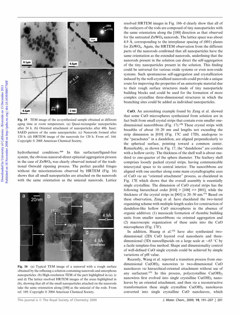
Fig. 15 TEM image of the as-synthesized sample obtained at different
aging time at room temperature. (a) Quasi-rectangular nanoparticles
after 24 h. (b) Oriented attachment of nanoparticles after 48h. Inset:
SAED pattern of the same nanoparticles. (c) Nanorods formed after
120 h. (d) HRTEM image of the nanorods for 120 h. From ref. 164.
Copyright ª 2008 American Chemical Society.
Dow
nloa
ded
by U
nive
rsity
of
Cal
ifor
nia
- R
iver
side
on
15 D
ecem
ber
2011
Publ
ishe
d on
18
Nov
embe
r 20
08 o
n ht
tp://
pubs
.rsc
.org
| do
i:10.
1039
/B80
7760
F
View Online
hydrothermal conditions.169 In this surfactant/ligand-free
system, the obvious nanorod-direct epitaxial aggregation process
in the case of ZnWO4 was clearly observed instead of the tradi-
tional Ostwald ripening process. The perfect parallel fringes
without the misorientations observed by HRTEM (Fig. 16)
shows that all small nanoparticles are attached on the nanorods
with the same orientation as the uniaxial nanorods. Lattice
Fig. 16 (a) Typical TEM image of a nanorod with a rough surface
obtained by the refluxing a solution containing nanorods and amorphous
nanoparticles. (b) High-resolution TEM of the part highlighted in (a). (c
and d) The lattice resolved HRTEM images of the areas highlighted in
(b), showing that all of the small nanoparticles attached on the nanorods
take the same orientation along [100] as the uniaxial of the rods. From
ref. 169. Copyright ª 2004 American Chemical Society.
This journal is ª The Royal Society of Chemistry 2009
resolved HRTEM images in Fig. 16b–d clearly show that all of
the outlayers of the rods are composed of tiny nanoparticles with
the same orientation along the [100] direction as that observed
for the untreated ZnWO4 nanorods. The lattice space was about
4.9 A, corresponding to the interplanar spacing of (001) planes
for ZnWO4. Again, the HRTEM observation from the different
parts of the nanorods confirmed that all nanoparticles have the
same orientation as the extended nanorods, underlining that the
nanorods present in the solution can direct the self-aggregation
of the tiny nanoparticles present in the solution. This finding
could be universal for various oxide systems or even non-oxide
systems. Such spontaneous self-aggregation and crystallization
induced by the well-crystallized nanorods could provide a unique
route for improving the properties of an anisotropic material due
to their rough surface structures made of tiny nanoparticle
building blocks and could be used for the formation of more
complex crystalline three-dimensional structures in which the
branching sites could be added as individual nanoparticles.
CuO. An astonishing example found by Zeng et al. showed
that some CuO microspheres synthesized from solution are in
fact built from small crystal strips that contain even smaller one-
dimensional nanoribbons (Fig. 17).170 These crystal strips with
breadths of about 10–20 nm and lengths not exceeding the
strip dimension in [010] (Fig. 17C and 17D), analogous to
the ‘‘parachutes’’ in a dandelion, are aligned perpendicularly to
the spherical surface, pointing toward a common center.
Remarkably, as shown in Fig. 17, the ‘‘dandelions’’ are coreless
with a hollow cavity. The thickness of the shell wall is about one-
third to one-quarter of the sphere diameter. The feathery shell
comprises loosely packed crystal strips, having communicable
intercrystal space to its central interior. The nanoribbons are
aligned with one another along some main crystallographic axes
of CuO via an ‘‘oriented attachment’’ process, as elucidated in
Fig. 17E which shows that the overall assembly is essentially
single crystalline. The dimension of CuO crystal strips has the
following hierarchical order [010] > [100] >> [001], while the
thickness of the crystal strips in [001] is 20–30 nm.171 Based on
these observation, Zeng et al. have elucidated the two-tiered
organizing scheme with multiple-length scales for construction of
dandelion-like hollow CuO microspheres in the absence of
organic additives: (1) mesoscale formation of rhombic building
units from smaller nanoribbons via oriented aggregation and
(2) macroscopic organization of these units into the CuO
microspheres (Fig. 17F).
In addition, Huang et al.172 have also synthesized two-
dimensional (2D) CuO layered oval nanosheets and three-
dimensional (3D) nanoellipsoids on a large scale at �65 �C by
a facile template-free method. Shape and dimensionality control
of well-defined CuO single crystals could be achieved by simple
variations of pH value.
Recently, Wang et al. reported a transition process from one-
dimensional Cu(OH)2 nanowires to two-dimensional CuO
nanoleaves via hierarchical-oriented attachment without use of
any surfactant.173 In this process, polycrystalline Cu(OH)2nanowires first evolved into single crystalline Cu(OH)2 nano-
leaves by an oriented attachment, and then via a reconstructive
transformation these single crystalline Cu(OH)2 nanoleaves
converted into single crystalline CuO nanoleaves, which
J. Mater. Chem., 2009, 19, 191–207 | 201

Fig. 17 (A and B) SEM images of two crashed CuOmicrospheres; (C and D) TEM images of two rhombic CuO crystal strips formed from smaller one-
dimensional nanoribbons; (E) SAED pattern ([001] zone) of the crystal strip shown in (D); (F) two-tier organization with multiple-length scales: (1)
oriented aggregation of CuO nanoribbons, and (2) concentric alignment of the preformed rhombic building blocks from (1). From ref. 170. Copyrightª2004 American Chemical Society.
Fig. 18 (A) Low-magnificationTEM image of a typicalAg nanodendrite
together with an ED pattern (inset); (B) higher magnification TEM image
of the Ag nanodendrite; (C) HRTEM image of the Ag nanodendrite in
a joint between the stem and a branch; (D) HRTEM image of the Ag
nanodendrite in a joint between a branch and a subbranch. From ref. 175.
Copyright ª 2006 American Chemical Society.
Dow
nloa
ded
by U
nive
rsity
of
Cal
ifor
nia
- R
iver
side
on
15 D
ecem
ber
2011
Publ
ishe
d on
18
Nov
embe
r 20
08 o
n ht
tp://
pubs
.rsc
.org
| do
i:10.
1039
/B80
7760
F
View Online
consisted of the nucleation of CuO followed by a two-step
oriented attachment of the CuO particles. The results demon-
strated that in the evolution process of CuO nanostructures,
from 0DCuO nanoparticles to 1D CuO nanoribbons and then to
2D CuO nanoleaves, oriented attachment is always playing
a significant role, and again the reduction of the overall surface
energy by eliminating the surfaces drives the oriented attachment
in the whole process.
Gd-doped CeO2. Very recently, Leite and coworkers174 have
demonstrated that the use of microwave heating during hydro-
thermal treatment can drastically decrease the treatment time
required to obtain gadolinium-doped ceria nanorods and that
the oriented attachment is the dominant mechanism responsible
for anisotropic growth, implying that it could be possible to
introduce the microwave irradiation technique as a parameter to
control oriented attachment and anisotropic growth of crystals.
Ag nanodendrites. Wen et al. have also synthesized silver
nanodendrites by a simple surfactant-free method using
a suspension of zinc microparticles as a heterogeneous reducing
agent.175 Fig. 18A shows a typical dendritic nanostructure at
a low magnification. The overall length of the dendrite is about
5 mm, and both the stem and the branches are 20–30 nm in
diameter. It is clear that the nanodendrite is highly symmetric,
and the angles between the stem and the branches are mostly
about 50–60�. The selected area electron diffraction (SAED)
pattern (Fig. 18A inset) displays discontinuous concentric rings
characteristic of the cubic Ag, indicating that although the whole
Ag nanodendrite is not a perfect single crystal, the structure has
a certain extent of preferential crystal orientation. The HRTEM
image in Fig. 18C from a subbranch (i.e., the third generation) of
the Ag nanodendrite shows a robust connection between the
202 | J. Mater. Chem., 2009, 19, 191–207
branch and the subbranch. It can be seen that continuous fringes
run through both stem and branch (Fig. 18C), indicating that the
connection between branch and stem is not simply a physical
This journal is ª The Royal Society of Chemistry 2009
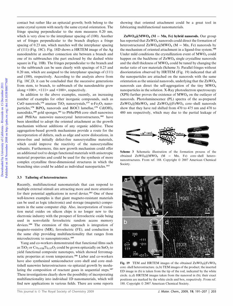
Scheme 3 Schematic illustration of the formation process of the
obtained ZnWO4@MWO4 (M ¼ Mn, Fe) core–shell hetero-
nanostructures. From ref. 188. Copyright ª 2007 American Chemical
Society.
Dow
nloa
ded
by U
nive
rsity
of
Cal
ifor
nia
- R
iver
side
on
15 D
ecem
ber
2011
Publ
ishe
d on
18
Nov
embe
r 20
08 o
n ht
tp://
pubs
.rsc
.org
| do
i:10.
1039
/B80
7760
F
View Online
contact but rather like an epitaxial growth; both belong to the
same crystal system with nearly the same crystal orientation. The
fringe spacing perpendicular to the stem measures 0.20 nm,
which is very close to the interplanar spacing of (100). Another
set of fringes perpendicular to the branch displays a fringe
spacing of 0.23 nm, which matches well the interplanar spacing
of (111) (Fig. 18C). Fig. 18D shows a HRTEM image of the Ag
nanodendrite at another connection site between a branch and
one of its subbranches (the part enclosed by the dashed white
square in Fig. 18B). The fringes perpendicular to the branch and
to the subbranch can be seen clearly with spacings of 0.23 and
0.20 nm, which are assigned to the interplanar spacings of (111)
and (100), respectively. According to the analysis above from
Fig. 18C,D, it can be concluded that the successive generations
from stem, to branch, to subbranch of the nanodendrite grow
along <100>, <111> and <100>, respectively.
In addition to the above examples, recently, an increasing
number of examples for other inorganic compounds, such as
CuO nanorods,176 anatase TiO2 nanocrystals,177 a-Fe2O3 nano-
particles,178 BiPO4 nanorods and BiOCl lamellae,179 Cd(OH)2nanodisks,180 gold sponges,181 to PbSe/PbS core–shell nanowires
and PbS/Au nanowire–nanocrystal heterostructures,182 have
been identified to adopt the oriented attachment as the growth
mechanism without additions of any organic additive. These
aggregation-based growth mechanisms provide a route for the
incorporation of defects, such as edge and screw dislocations, in
stress-free and initially defect-free nanocrystalline materials,
which could improve the reactivity of the nanocrystalline
subunits. Furthermore, this new growth mechanism could offer
an additional tool to design functional materials with anisotropic
material properties and could be used for the synthesis of more
complex crystalline three-dimensional structures in which the
branching sites could be added as individual nanoparticles.163
Fig. 19 TEM and HRTEM images of the obtained ZnWO4@FeWO4
core–shell heterostructure. (a,b) TEM images of the product; the inserted
ED image in (b) is taken from the tip of the rod, indicated by the white
circle. (c,d) HRTEM images taken from the nanorod in (b); their exact
positions are marked by the white circle and box, respectively. From ref.
188. Copyright ª 2007 American Chemical Society.
3.3 Tailoring of heterostructures
Recently, multifunctional nanomaterials that can respond to
multiple external stimuli are attracting more and more attention
for their potential applications in novel device.183 One of these
well-known examples is that giant magneto-resistant materials
can be used as logic (electronic) and storage (magnetic) compo-
nents in the same computer chip. Also, incorporation of transi-
tion metal oxides on silicon chips is no longer new to the
electronic industry with the prospect of ferroelectric oxide being
used in nonvolatile ferroelectric random access memory
devices.184 The extension of this approach is integration of
magneto-resistive (MR), ferroelectric (FE), and conduction in
the same chip providing multifunctionality that ranges from
microelectronic to nanospintronics.185
Yang and co-workers demonstrated that functional films such
as TiO2 or Co0.05BTi0.95O2 could be grown epitaxially on SnO2 to
yield functional composite nanotapes, which showed ferromag-
netic properties at room temperature.186 Lieber and co-workers
have also synthesized semiconductor core–shell and core–mul-
tishell nanowire heterostructures via epitaxial growth by modu-
lating the composition of reactant gases in sequential steps.187
These investigations clearly show the possibility of incorporating
multifunctionality into individual 1D nanomaterials, which will
find new applications in various fields. There are some reports
This journal is ª The Royal Society of Chemistry 2009
showing that oriented attachment could be a great tool in
fabricating multifunctional nanomaterials.
ZnWO4@MWO4 (M ¼ Mn, Fe) hybrid nanorods. Our group
has reported that ZnWO4 nanorods could direct the formation of
heterostructured ZnWO4@MWO4 (M ¼ Mn, Fe) nanorods by
the mechanism of oriented attachment in a ligand-free system.188
Under mild conditions the crystallization event of MWO4 could
happen on the backbone of ZnWO4 single crystalline nanorods
and the shell thickness of MWO4 could be tuned by changing the
molar ratio of raw materials (Scheme 3). Parallel fringes without
disorientation observed by HRTEM (Fig. 19) indicated that all
the nanoparticles are attached on the nanorods with the same
orientation as the uniaxial nanorods, underlying that the ZnWO4
nanorods can direct the self-aggregation of the tiny MWO4
nanoparticles in the solution. X-Ray photoelectron spectroscopy
(XPS) further proves the existence of MWO4 on the outlayer of
nanorods. Photoluminescence (PL) spectra of the as-prepared
ZnWO4@MnWO4 and ZnWO4@FeWO4 core–shell nanorods
show that they have red shifted from 470 to 475 nm and 470 to
480 nm respectively, which may due to the partial leakage of
J. Mater. Chem., 2009, 19, 191–207 | 203
Dow
nloa
ded
by U
nive
rsity
of
Cal
ifor
nia
- R
iver
side
on
15 D
ecem
ber
2011
Publ
ishe
d on
18
Nov
embe
r 20
08 o
n ht
tp://
pubs
.rsc
.org
| do
i:10.
1039
/B80
7760
F
View Online
excitons into the MnWO4 or FeWO4 matrix. In addition, the
phenomenon of antiferromagnetic ordering was observed in
these two heterostructures. Thus, this new kind of
ZnWO4@MWO4(M ¼ Mn, Fe) core–shell nanorod with both
optical and antiferromagnetic properties may have potential
applications.
PbSe/PbS core–shell nanowires. The protection of nano-
materials against oxidation with a thin inorganic epitaxial shell is
widely used in highly luminescent II–VI and III–V nanocrystals
and nanorods.189–192 To improve the stability and processability
of colloidal PbSe nanowires, Talapin et al.182 studied the
formation of coaxial PbSe/PbS core-shell heterostructures via
oriented attachment above 180 �C. As shown in Fig. 20a, addi-
tion of cubic PbS nanoparticles to a colloidal solution of PbSe
nanowires in trioctylamine at 120 �C results in a uniform deco-
ration of the nanowires with PbS nanoparticles. The driving
force in this process is the van der Waals interactions between
nanowires and nanocrystals. Nanoparticle self-assembly can
progress toward the formation of thick layers of nanocubes
assembled around PbSe nanowires (Fig. 20b). This self-assembly
approach can generate fairly thick PbS ‘‘shells’’ around PbSe
nanowires, whereas the shells grown from the molecular
precursors are usually only a few nanometers thick. Annealing
Fig. 20 (a–c) PbSe nanowires with straight, zigzag, and branched
morphologies, respectively, used as templates. (d) PbSe-Au nano-
composites synthesized using PbSe nanowires with different morphol-
ogies. From ref. 182. Copyright ª 2007 American Chemical Society.
204 | J. Mater. Chem., 2009, 19, 191–207
the nanostructures at 180 �C for 15 min promoted at least partial
oriented attachment between nanoparticles and nanowires as
show in Fig. 20c. The matching of the lattice fringes in the PbSe
nanowire and adjacent PbS nanoparticles as well as the single-
crystal like selected area electron diffraction pattern (Fig. 20d)
confirm the fusion of PbS nanoparticles with the PbSe nanowire.
Decoration of PbSe nanowires with PbS nanoparticles provides
a promising architecture for photovoltaic cells with carrier
multiplication.
There is some other evidence for oriented attachment as
a versatile tool in fabricating heterostructures. For example,
Ribeiro et al. reported the formation of TiO2/SnO2 hetero-
structures taking advantage of oriented attachment
mechanics.193 Hence, it is expected that this mechanism will open
up a new avenue for construction and assembly of multifunc-
tional nanostructures.
4. Summary and outlook
In this paper, the state-of-the-art in the area of the new crystal
growth mechanism, so called ‘‘oriented attachment’’, and its
potential for application in shape control of a variety of inor-
ganic crystals has been overviewed, including the basic principles
and potentials with specific examples, which are very promising
for morphology and shape control of various inorganic materials
in solution-based systems. The universal applicability of the
classical crystallization mechanism was already questioned a few
years ago, and the development of alternative crystallization
mechanisms is still an important and challenging task.
This oriented attachment mechanism is an important concept
involving particle based crystallization pathways. It can yield
crystal morphologies that cannot be nucleated via a classical ion/
molecule based crystallization mechanism. Both the formation
and the morphogenesis of single crystals according to this new
mechanism apparently contradict the classical textbook knowl-
edge on crystallization, where the growth of shaped crystals is
based on the integration of atoms/molecules onto energetically
favorable sites on a growing crystal face.194,195 The adsorption of
ions or molecules onto the crystal face is followed by subsequent
diffusion across the surface to steps and kink sites196 and leads to
a plane-by-plane growth of a single crystal. The relevant
parameters for classical crystallization include molecular solu-
bility (defining the speed of crystallization) and crystal face
specific interface tensions defining growth rates, relative exposure
and accordingly the morphology of a crystal. However, all these
characteristics are certainly not valid for oriented attachment,
which is a particle mediated crystallization pathway involving
mesoscopic transformation instead.197
The emerging oriented attachment process observed under
near natural crystallization conditions and spontaneous self-
organization of unstabilized nanoparticles could shed new light
on understanding of the detailed interaction mechanism between
inorganic nanoparticles and their subsequent higher order
self-assembly mechanism.198 In earlier studies, organic additives
had been found to be the key factor for oriented attachment
growth, and many surfactants had been used to synthesize
anisotropic nanomaterials. However, recent progress has
provided strong evidence that perfect nanostructures can be
conveniently self-assembled from tiny nanoparticles even
This journal is ª The Royal Society of Chemistry 2009
Dow
nloa
ded
by U
nive
rsity
of
Cal
ifor
nia
- R
iver
side
on
15 D
ecem
ber
2011
Publ
ishe
d on
18
Nov
embe
r 20
08 o
n ht
tp://
pubs
.rsc
.org
| do
i:10.
1039
/B80
7760
F
View Online
without any organic additives based on the oriented attachment
mechanism. There are still an increasing number of examples
based on oriented attachment and without any organic additives.
However, it has to be pointed out that we are still far away from
a full understanding of this new growth mechanism, and it is
undoubtedly necessary to further investigate this emerging
mechanism both experimentally and theoretically.
This new solution route based on the oriented attachment
mechanism will certainly open alternative doorways toward
rationally designing various kinds of inorganic materials and
even multi-component hybrid materials with unique structures,
ideal hierarchy, controllable length scale, and multi-functional-
ities, which will shed new light on their novel applications and
fundamental properties.
Acknowledgements
S.-H. Yu acknowledges the funding support from the National
Science Foundation of China (NSFC, Grant Nos. 50732006,
20621061, 20671085, 2005CB623601), Anhui Development Fund
for Talent Personnel and Anhui Education Committee
(2006Z027, ZD2007004-1), the Specialized Research Fund for
the Doctoral Program (SRFDP) of Higher Education State
Education Ministry, and the Partner-Group of the Chinese
Academy of Sciences–the Max Planck Society.
References
1 C. Burda, X. B. Chen, R. Narayanan and M. A. El-Sayed, Chem.Rev., 2005, 105, 1025.
2 E. R. Leite, Nanocrystals assembled from the bottom up, in:Encyclopedia of Nnanoscience and Nanotechnology, ed. H. S.Nalwa, American Scientific Publishers, Stevenson Ranch, CA,2004, p. 537.
3 A. P. Alivisatos, J. Phys. Chem., 1996, 100, 13226.4 H. Boukari, J. S. Lin and M. T. Harris, J. Colloid Interface Sci.,1997, 194, 311.
5 M. Z. C. Hu, M. T. Harris and C. H. Byers, J. Colloid Interface Sci.,1998, 198, 87.
6 X. G. Peng, J. Wickham and A. P. Alivisatos, J. Am. Chem. Soc.,1998, 120, 5343.
7 X. G. Peng, L. Manna, W. D. Yang, J. Wickham, E. Scher,A. Kadavanich and A. P. Alivisatos, Nature, 2000, 404, 59.
8 T. Hyeon, S. S. Lee, J. Park, Y. Chung and H. B. Na, J. Am. Chem.Soc., 2001, 123, 12798.
9 V. F. Puntes, K. M. Krishnan and A. P. Alivisatos, Science, 2001,291, 2115.
10 T. Hyeon, Y. Chung, J. Park, S. S. Lee, Y. W. Kim and B. H. Park,J. Phys. Chem. B, 2002, 106, 6831.
11 V. R. Calderone, A. Testino, M. T. Buscaglia, M. Bassoli,C. Bottino, M. Viviani, V. Buscaglia and P. Nanni, Chem. Mater.,2006, 18, 1627.
12 Z. Y. Tang, N. A. Kotov and M. Giersig, Science, 2002, 297, 237.13 Y. Volkov, S. Mitchell, N. Gaponik, Y. P. Rakovich, J. F. Donegan,
D. Kelleher and A. L. Rogach, ChemPhysChem., 2004, 5, 1600.14 J. Polleux, N. Pinna, M. Antonietti and M. Niederberger, Adv.
Mater., 2004, 16, 436.15 Y. W. Jun, M. F. Casula, J. H. Sim, S. Y. Kim, J. Cheon and
A. P. Alivisatos, J. Am. Chem. Soc., 2003, 125, 15981.16 B. Cheng, J. M. Russel, W. Shi, L. Zhang and E. T. Samulski, J. Am.
Chem. Soc., 2004, 126, 5972.17 L. Vayssieres and M. Graetzel, Angew. Chem. Int. Ed., 2004, 43,
3666.18 I. I. Naumov, L. Bellaiche and H. X. Fu, Nature, 2004, 432, 737.19 Y. Xia, P. Yang, Y. Sun, Y. Wu, B. Mayers, B. Gates, Y. Yin,
F. Kim and H. Yan, Adv. Mater., 2003, 15, 353.20 R. J. Davey, Nature, 2004, 428, 374.21 W. F. Ostwald, Phys. Chem., 1897, 22, 289.
This journal is ª The Royal Society of Chemistry 2009
22 I. M. Lifshitz and V. V. Slyozov, Phys. Chem. Solids, 1961, 22, 35.23 C. Wagner, Thoerie der altering von neiderschlagen durch umlosen. Z
Elektrochem., 1961, 65, 581.24 H. Gratz, Scrip. Mater., 1997, 37, 9.25 S. A. Kukushkin and A. V. Osipov, J. Exp. Theor. Phys., 1998, 86,
1201.26 Z. S. Hu, G. Oskam, R. L. Penn, N. Pesika and P. C. Searson,
J. Phys. Chem. B., 2003, 107, 3124.27 G. Oskam, Z. S. Hu, R. L. Penn, N. Pesika and P. C. Searson, Phys.
Rev. E., 2002, 66, 011403.28 G. Oskam, A. Nellore, R. L. Penn and P. C. Searson, J. Phys. Chem.
B., 2003, 107, 1734.29 P. Jensen, Rev. Mod. Phys., 1999, 71, 1695.30 R. L. Penn and J. F. Banfield, Am. Mineral., 1998, 83, 1077.31 R. L. Penn and J. F. Banfield, Science, 1998, 281, 969.32 R. L. Penn and J. F. Banfield, Geochim. Cosmochim. Acta., 1999, 63,
1549.33 F. Banfield, S. A. Welch, H. Zhang, T. T. Ebert and R. L. Penn,
Science, 2000, 289, 751.34 R. L. Penn, G. Oskam, T. J. Strathmann, P. C. Searson, A. T. Stone
and D. R. Veblen, J. Phys. Chem. B, 2001, 105, 2177.35 A. Navrostsky, Proc. Natl. Acad. Sci., 2004, 101, 12096.36 E. J. H. Lee, C. Ribeiro, E. Longo and E. R. Leite, J. Phys. Chem. B,
2084, 2005, 109.37 J. K. Bailey, C. J. Brinker andM. L. Mecartney, J. Colloid Interface.
Sci., 1993, 157, 1.38 M. Ocana, M. P. Morales and C. J. Serna, J. Colloid Interface Sci.,
1995, 171, 85.39 Y. F. Zhu, W. R. Zhao, H. R. Chen and J. L. Shi, J. Phys. Chem. C,
2007, 111, 5281.40 V. Privman, D. V. Goia, J. Park and E. Matijevic, J. Colloid
Interface Sci., 1999, 213, 36.41 K. Onuma and A. Ito, Chem. Mater., 1998, 10, 3346.42 K. S. Cho, D. V. Talapin, W. Gaschler and C. B. Murray, J. Am.
Chem. Soc., 2005, 127, 7140.43 E. R. Leite, T. R. Giraldi, F. M. Pontes, E. Longo, A. Beltran and
J. Andres, Appl. Phys. Lett., 2003, 83, 1566.44 M. Adachi, Y. Murata, J. Takao, J. Jiu, M. Sakamoto and F. Wang,
J. Am. Chem. Soc., 2004, 126, 14943.45 A. Chemseddine and T. Moritz, Eur. J. Inorg. Chem., 1999, 235.46 F. Huang, H. Z. Zhang and J. F. Banfield, Nano. Lett., 2003, 3, 373.47 J. H. Yu, J. Joo, H. M. Park, S. I. Baik, Y. W. Kim, S. C. Kim and
T. Hyeon, J. Am. Chem. Soc., 2005, 127, 5662.48 A. P. Alivisatos, Science, 2000, 289, 736.49 J. A. Dirksen and T. A. Ring, Chem. Eng. Sci., 1991, 46, 2389.50 C. B. Murray, C. R. Kagan and M. G. Bawendi, Annu. Rev. Mater.
Sci., 2000, 30, 545.51 B. R. Pamplin. Crystal Growth. Pergamon Press: New York, 1975.52 Y. Jiang, in: Handbook of nanophase and nanostructured materials,
eds. Z. L. Wang, Y. Liu and Z. Zhang, Kluwer Academic/PlenumPublishers and Tsinghua University Press, 2003, p. 244.
53 I. V. Markov, Crystal growth for beginners: fundamentals ofnucleation, crystal growth and epitaxy, World Scientific PublishingCo. Pte. Ltd, Singapore, 2003.
54 G. Cao, Nanostructures & Nanomaterials: Synthesis, Properties, &Applications. Imperial College Press, London, 2004.
55 J. D. Yoreo and T. Land, Sci. Tech. Rev., 1996, 9, 12.56 H. C€olfen and S. Mann, Angew. Chem. Int. Ed., 2003, 42, 2350.57 S. Wohlrab, N. Pinna, M. Antonietti and H. C€olfen, Chem. Eur. J.,
2005, 11, 2903.58 H. C€olfen and M. Antonietti, Angew. Chem. Int. Ed., 2005, 44, 5576.59 A. N. Kulak, P. Iddon, Y. T. Li, S. P. Armes, H. C€olfen, O. Paris,
R. M. Wilson and F. C. Meldrum, J. Am. Chem. Soc., 2007, 129,3729.
60 D. Schwahn, Y. R. Ma and H. C€olfen, J. Phys. Chem. C., 2007, 111,3224.
61 X. Y. Chen, M. H. Qiao, S. H. Xie, K. N. Fan, W. Z. Zhou andH. Y. He, J. Am. Chem. Soc., 2007, 129, 13305.
62 T. Vossmeyer, G. Reck, L. Katsikas, E. T. K. Haupt, B. Schulz andH. Weller, Science, 1995, 267, 1476.
63 O. Pujol, P. Bowen, P. A. Stadelmann and H. Hofmann, J. Phys.Chem. B., 2004, 108, 13128.
64 X. H. Guo and S. H. Yu, Cryst. Growth. Des., 2007, 7, 354.65 X. H. Guo, A. W. Xu and S. H. Yu, Cryst. Growth. Des., 2007, 7,
354.
J. Mater. Chem., 2009, 19, 191–207 | 205
Dow
nloa
ded
by U
nive
rsity
of
Cal
ifor
nia
- R
iver
side
on
15 D
ecem
ber
2011
Publ
ishe
d on
18
Nov
embe
r 20
08 o
n ht
tp://
pubs
.rsc
.org
| do
i:10.
1039
/B80
7760
F
View Online
66 A. W. Xu, M. Antonietti, H. C€olfen and Y. P. Fang, Adv. Funct.Mater., 2006, 16, 903.
67 M. G. Page and H. C€olfen, Cryst. Growth. Des., 2006, 6, 1915.68 T. X. Wang, M. Antonietti and H. C€olfen, Chem. Eur. J., 2006, 12,
5722.69 J. Zhan, H. P. Lin and C. Y. Mou, Adv. Mater., 2003, 15, 621.70 O. Grassmann, R. B. Neder, A. Putnis and P. L€obmann, Am.
Mineral., 2003, 88, 647.71 S. H. Yu and H. C€olfen, J. Mater. Chem., 2004, 14, 2124.72 O. Grassmann and P. L€obmann, Chem. Eur. J., 2003, 9, 1310.73 S. H. Yu, H. C€olfen, K. Tauer andM. Antonietti, Nat. Mater., 2005,
4, 51.74 Y. R. Ma, H. C€olfen and M. Antonietti, J. Phys. Chem. B., 2006,
110, 10822.75 E. V. Shevchenko, D. V. Talapin, A. L. Rogach, A. Kornowski,
M. Hasse and H. Weller, J. Am. Chem. Soc., 2002, 124, 11480.76 K. X. Yao and H. C. Zeng, J. Phys. Chem. C., 2007, 111, 13301.77 J. X. Fang, X. N. Ma, H. H. Cai, X. P. Song and B. J. Ding,
Nanotechnology, 2006, 17, 5841.78 J. X. Fang, B. J. Ding and X. P. Song, Appl. Phys. Lett., 2007, 91,
083108.79 J. P. Ge, Y. X. Hu, M. Biazini, W. P. Beyemann and Y. D. Yin,
Angew. Chem. Int. Ed., 2007, 46, 4342.80 E. Beniash, J. Aizenberg, L. Addadi and S. Weiner, Proc. R. Soc.
London, Ser. B, 1997, 264, 461.81 E. Beniash, L. Addadi and S. Weiner, J. Struct. Biol., 1999, 125, 50.82 L. Addadi, S. Raz and S. Weiner, Adv. Mater., 2003, 15, 959.83 S. Raz, P. C. Hamilton, F. H. Wilt, S. Weiner and L. Addadi, Adv.
Funct. Mater., 2003, 13, 480.84 J. Aizenberg, G. Lambert, S. Weiner and L. Addadi, J. Am. Chem.
Soc., 2002, 124, 32.85 Y. Politi, T. Arad, E. Klein, S. Weiner and L. Addadi, Science, 2004,
306, 1161.86 S. Weiner, I. Sagi and L. Addadi, Science, 2005, 309, 1027.87 Y. Oaki and H. Imai, Small, 2006, 2, 66.88 M. Rousseau, E. Lopez, P. Stempfle, M. Brendle, L. Franke,
A. Guette, R. Naslain and X. Bourrat, Biomaterials, 2005, 26, 6254.89 Y. Oaki and H. Imai, Angew. Chem. Int. Ed., 2005, 44, 6571.90 M. Antonietti, M. Breulmann, C. G. G€otner, H. C€olfen,
K. K. W. Wong, D. Walsh and S. Mann, Chem. Eur. J., 1998, 4,2493.
91 L. M. Qi, H. C€olfen, M. Antonietti, M. Li, J. D. Hopwood,A. J. Ashley and S. Mann, Chem. Eur. J., 2001, 7, 3526.
92 S. H. Yu, H. C€olfen and M. Antonietti, Chem. Eur. J., 2002, 8, 2937.93 S. H. Yu, M. Antonietti, H. C€olfen and J. Hartmann, Nano Lett.,
2003, 3, 379.94 H. C}olfen, in: Biomimeralization: from paleontology to materials
science, eds. J. L. Arias and M. S. Fernandez, EditorialUniversitaria, Universidad de Chile, Santiago, Chile, 2006.
95 E. Matijevic, Chem. Mater., 1993, 5, 412.96 E. Matijevic, Curr. Opin. Colloid Interface Sci., 1996, 1, 176.97 T. Sugimoto, Adv. Colloid Interface Sci., 1987, 28, 65.98 J. W. Mullin, in: Crystallization (3rd Edition), Butterworth-
Heinemann, Stoneham, MA, 1997.99 H. L. Zhu and R. S. Averback, Philos. Mag. Lett., 1996, 73, 27.100 M. Yeadon, M. Ghaly, J. C. Yang, R. S. Averback and
J. M. Gibson, Appl. Phys. Lett., 1998, 73, 3208.101 R. L. Penn, J. Phys. Chem. B, 2004, 108, 12707.102 C. Ribeiro, E. J. H. Lee, E. Longo and E. R. Leite, ChemPhysChem,
2006, 7, 664.103 T. O. Drews, M. A. Katsoulakis andM. Tsapatsis, J. Phys. Chem. B,
2005, 109, 23879.104 H. G. Yang and H. C. Zeng, Angew. Chem. Int. Ed., 2004, 43, 5930.105 H. C. Zeng, J. Mater. Chem., 2006, 16, 649.106 J. A. Venables, in: Introduction to surface and thin film processes,
Cambridge University Press, Cambridge, 2000.107 H. E. Buckley. Crystal growth., 1951.108 I. J. W. Mullin. Crystallization. Butterworths, London, 1971.109 A. A. Chernov, J. Cryst.Growth., 1974, 24/25, 11.110 T. Kudora, T. Irisawa and A. Ookawa, J. Cryst. Growth., 1977,
42, 41.111 W. F. Berg, Proc. R. Soc. London Ser. A., 1938, 164, 79.112 C. W. Bunn, Discuss Faraday Soc., 1949, 5, 132.113 S. H. Yu, Top Curr. Chem., 2007, 271, 79.114 Z. L. Wang, J. Phys. Chem. B, 2000, 104, 1153.
206 | J. Mater. Chem., 2009, 19, 191–207
115 H. C€olfen, Top Curr. Chem., 2007, 271, 1.116 G. Garnweitner and M. Niederberger, J. Mater. Chem., 2008, 18,
1171.117 S. H. Yu and S. F. Chen, Current Nanosci., 2006, 2, 81.118 A. C. Curtis, D. G. Duff, P. P. Edwards, D. A. Jefferson,
B. F. G. Johnson, A. I. Kirkland and A. S. Wallace, Angew.Chem. Int. Ed., 1988, 27, 1530.
119 T. S. Ahmadi, Z. L. Wang, T. C. Green, A. Henglein and M. A. El-Sayed, Science, 1996, 272, 1924.
120 J. S. Bradley, B. Tesche, W. Busser, M. Maase and M. T. Reetz,J. Am. Chem. Soc., 2000, 122, 4631.
121 Y. Sun and Y. Xia, Science, 2002, 298, 2176.122 N. K. Raman, M. T. Anderson and C. J. Brinker, Chem. Mater.,
1996, 8, 1682.123 S. Mann, S. L. Burkett, S. A. Davis, C. E. Fowler, N. H. Mendelson,
S. D. Sims, D. Walsh and N. T. Whilton, Chem. Mater., 1997, 9,2300.
124 L. A. Estroff and A. D. Hamilton, Chem. Mater., 2001, 13, 3227.125 S. A. Davis, M. Breulmann, K. H. Rhodes, B. Zhang and S. Mann,
Chem. Mater., 2001, 13, 3218.126 R. A. Caruso and M. Antonietti, Chem. Mater., 2001, 13, 3272.127 K. J. C. van Bommel, A. Friggeri and S. Shinkai, Angew. Chem. Int.
Ed., 2003, 42, 980.128 J. Polleux, N. Pinna,M. Antonietti, C. Hess, U.Wild, R. Schl€ogl and
M. Niederberger, Chem. Eur. J., 2005, 11, 3541.129 M. Niederberger, M. H. Bartl and G. D. Stucky, J. Am. Chem. Soc.,
2002, 124, 13642.130 M. Niederberger, G. Garnweitner, F. Krumeich, R. Nesper,
H. C€olfen and M. Antonietti, Chem. Mater., 2004, 16, 1202.131 M. Niederberger, M. H. Bartl and G. D. Stucky, Chem. Mater.,
2002, 14, 4364.132 L. Wang, X. Guan, H. Yin, J. Moradian-Oldak and
G. H. Nancollas, J. Phys. Chem. C, 2008, 112, 5892.133 N. Pradhan, H. Xu and X. G. Peng, Nano. Lett., 2006, 6, 720.134 L.Manna, E. C. Scher and A. P. Alivisatos, J. Am. Chem. Soc., 2000,
122, 12700.135 Z. A. Peng and X. Peng, J. Am. Chem. Soc., 2001, 123, 1389.136 P. D. Cozzoli, L. Manna, M. L. Curri, S. Kudera, C. Giannini,
M. Striccoli and A. Agostiano, Chem. Mater., 2005, 17, 1296.137 J. W. Grebinski, K. L. Hull, J. Zhang, T. H. Kosel and M. Kuno,
Chem. Mater., 2004, 16, 5260.138 C. Ma and Z. L. Wang, Adv. Mater., 2005, 17, 2635.139 A. Halder and N. Ravishankar, Adv. Mater., 2007, 19, 1854.140 D. Zitoun, N. Pinna, N. Frolet and C. Belin, J. Am. Chem. Soc.,
2005, 127, 15034.141 Z. Tang and N. A. Kotov, Adv. Mater., 2005, 17, 951.142 Z. P. Zhang, H. Sun, X. Shao, D. Li, H. Yu and M. Han, Adv.
Mater., 2005, 17, 42.143 M. Li, H. Schnablegger and S. Mann, Nature, 1999, 402, 393.144 M. Li and S. Mann, Langmuir, 2000, 16, 7088.145 L. M. Qi, H. C€olfen andM. Antonietti, Angew. Chem. Int. Ed., 2000,
39, 604.146 L. M. Qi, H. C€olfen and M. Antonietti, Chem. Mater., 2000, 12,
2392.147 M. Li, S. Mann and H. C€olfen, J. Mater. Chem., 2004, 14, 2269.148 S. H. Yu, H. C€olfen and M. Antonietti, Adv. Mater., 2003, 15, 133.149 B. Liu, S. H. Yu, L. Li, Q. Zhang, F. Zhang and K. Jiang, Angew.
Chem. Int. Ed., 2004, 43, 4745.150 D. Kuang, A. Xu, Y. Fang, H. Liu, C. Frommen and D. Fenske,
Adv. Mater., 2003, 15, 1747.151 Y.Ma, L. Qi, J. Ma and H. Cheng, Cryst. Growth. Des., 2004, 4, 351.152 Q. Zhang, W. T. Yao, X. Y. Chen, L. W. Zhu, Y. B. Fu,
G. B. Zhang, L. S. Sheng and S. H. Yu, Cryst. Growth. Des., 2007,7, 1423.
153 T. He, D. Chen and X. Jiao, Chem. Mater., 2004, 16, 737.154 R. Si, Y. W. Zhang, L. P. You and C. H. Yan, J. Phys. Chem. B,
2006, 110, 5994.155 F. Zuo, S. Yan, B. Zhang, Y. Zhao and Y. Xie, J. Phys. Chem. C,
2008, 112, 2831.156 W. M. Du, X. F. Qian, X. S. Niu and Q. Gong, Cryst. Growth. Des.,
2007, 7, 2733.157 R. L. Penn, A. T. Stone and D. R. Veblen, J. Phys. Chem. B, 2001,
105, 4690.158 N. Gehrke, H. C€olfen, N. Pinna,M. Antonietti and N. Nassif, Cryst.
Growth. Des., 2005, 5, 1317.
This journal is ª The Royal Society of Chemistry 2009
Dow
nloa
ded
by U
nive
rsity
of
Cal
ifor
nia
- R
iver
side
on
15 D
ecem
ber
2011
Publ
ishe
d on
18
Nov
embe
r 20
08 o
n ht
tp://
pubs
.rsc
.org
| do
i:10.
1039
/B80
7760
F
View Online
159 J. M. Song, Y. J. Zhan, A. W. Xu and S. H. Yu, Langmuir, 2007, 23,7321.
160 M. Giersig, I. PastorizaiSantos and L. M. Liz-Marzan, J. Mater.Chem., 2004, 14, 607.
161 Y. Yamauchi, T. Momma, M. Fuziwara, S. S. Nair, T. Ohsuna,O. Terasaki, T. Osaka andK. Kuroda, Chem. Mater., 2005, 17, 6342.
162 Z. T. Deng, D. Chen, F. Q. Tang, X.W.Meng, J. Ren and L. Zhang,J. Phys. Chem. C, 2007, 14, 5325.
163 C. Pacholski, A. Kornowski and H. Weller, Angew. Chem. Int. Ed.,2002, 41, 1188.
164 R. R. Hawaldar, S. D. Sathaye, A. Harle, R. S. Gholap andK. R. Patil, J. Phys. Chem. C, 2008, 112, 7557.
165 C. C. Tsai and H. Teng, Chem. Mater., 2004, 16, 4352.166 C. C. Tsai and H. Teng, Chem. Mater., 2006, 18, 367.167 J. N. Nian and H. Teng, J. Phys. Chem. B, 2006, 110, 4193.168 M. P. Finnegan, H. Zhang and J. F. Banfield, Chem. Mater., 2008,
20, 3443.169 B. Liu, S. H. Yu, L. Li, F. Zhang, Q. Zhang, M. Yoshimura and
P. Shen, J. Phys. Chem., 2004, 108, 2788.170 B. Liu and H. C. Zeng, J. Am. Chem. Soc., 2004, 126, 8124.171 Y. Chang and H. C. Zeng, Cryst. Growth. Des., 2004, 4, 397.172 J. Liu, X. Huang, Y. Li, K. M. Sulieman, X. He and F. Sun, Cryst.
Growth. Des., 2006, 6, 1690.173 H. L. Xu, W. Z. Wang, W. Zhu, L. Zhou and M. L. Ruan, Cryst.
Growth. Des., 2007, 7, 2720.174 M. Godinho, C. Ribeiro, E. Longo and E. R. Leite, Cryst. Growth.
Des., 2008, 8, 384.175 X. Wen, Y. T. Xie, M. W. C. Mak, K. Y. Cheung, X. Y. Li,
R. Renneberg and S. Yang, Langmuir, 2006, 22, 4836.176 W. T. Yao, S. H. Yu, Y. Zhou, J. Jiang, Q. S. Wu, L. Zhang and
J. Jiang, J. Phys. Chem. B, 2005, 109, 14011.177 C. H. Cho, M. H. Han, D. H. Kim and D. K. Kim, Mater. Chem.
Phys., 2005, 92, 104.178 C. Frandsen, C. R. H. Bahl, B. Lebech, K. Lefmann, L. Theil Kuhn,
L. Keller, N. H. Andersen, M. V. Zimmermann, E. Johnson,S. N. Klausen and S. Mørup, Phys. Rev. B, 2005, 72, 214406–1.
This journal is ª The Royal Society of Chemistry 2009
179 J. Geng, W. H. Hou, Y. N. Lv, J. J. Zhu and H. Y. Chen, Inorg.Chem., 2005, 44, 8503.
180 W. Shi, C.Wang, H.Wang andH. Zhang, Cryst. Growth. Des., 2006,6, 915.
181 Y. X. Zhang and H. C. Zeng, J. Phys. Chem. C, 2007, 111, 6970.182 D. V. Talapin, H. Yu, E. V. Shevchenko, A. Lobo and C. B.Murray,
J. Phys. Chem. C, 2007, 111, 14049.183 L. Wang, J. Bai, Y. Li and Y. Huang, Angew. Chem. Int. Ed., 2008,
47, 2439.184 V. L. Mathe, J. Magn. Magn. Mater., 2003, 263, 344.185 S. Jin, T. H. Tiefel, M. McCormack, R. A. Fastnacht, R. Ramesh
and L. H. Chen, Sicence, 1994, 264, 413.186 R. H. He, M. Law, R. Fan, F. Kim and P. D. Yang, Nano Lett.,
2002, 2, 1109.187 L. J. Lauhon, M. S. Gudiksen, D. Wang and C. M. Lieber, Nature,
2002, 420, 57.188 Q. Zhang, X. Y. Chen, Y. X. Zhou, G. B. Zhang and S. H. Yu,
J. Phys. Chem. C, 2007, 111, 3927.189 M. A. Hines and P. Guyot-Sionnest, J. Phys. Chem., 1996, 100, 468.190 D. V. Talapin, I. Mekis, S. Gotzinger, A. Kornowski, O. Benson and
J. Weller, J. Phys. Chem. B, 2004, 108, 8826.191 Y. W. Cao and U. Banin, J. Am. Chem. Soc., 2000, 12, 9692.192 L. Manna, E. C. Scher, L. S. Li and A. P. Alivisatos, J. Am. Chem.
Soc., 2002, 124, 7136.193 C. Ribeiro, E. Longo and E. R. Leite, Appl. Phys. Lett., 2007, 91,
103105.194 W. Kossel. Mathematisch-Physische Klasse, 1927, pp. 135–143.195 I. N. Stranski, Z. Phys. Chem., 1928, 136, 259.196 W. K. Burton, N. Cabrera and F. C. Frank, Philos. Trans. R. Soc.
London Ser. A, 1951, 243, 299.197 M. Niederberger and H. C€olfen, Phys. Chem. Chem. Phys., 2006, 8,
3271.198 S. H. Yu and H. C€olfen, ‘‘Nature-inspired Nanoparticle
Superstructures’’, in: Nanoparticle Superstructures, CRC Press,Taylor & Francis Group, FL, ed. N. N. Kotov, 2005, Chapter 11,pp. 269–338.
J. Mater. Chem., 2009, 19, 191–207 | 207