ADoc-Oriented Programming
25
1 ADoc-Oriented Programming Prabir Nandi, Santhosh Kumaran Terry Heath IBM T. J. Watson Research Center Route 134 Yorktown Heights, NY Kumar Bhaskaran, Raja Das IBM Software Group Route 100 Somers, NY ABSTRACT In this paper, we present a new programming model targeted to collaborative business process integration applications. This model is based on the object-oriented technology, but elevates the programming model to cover a new breed of business applications that are currently evolving. These applications are differentiated by their strong emphasis on “collaborations” in which a set of “collaborators” works together to attain business objectives, and on integration where new functionality is derived by integrating legacy systems with new components and applications. We propose two new modeling artifacts, ADoc (Adaptive Document) and Collaboration, to model this class of applications. We propose an XML-based language to assemble ADoc-based collaborative applications. We present the design of a runtime environment for ADocs and discuss the current implementation of this runtime. We present an in depth analysis of this programming model. We discuss our experience in using this model in real world applications. 1. INTRODUCTION As application areas for computer systems evolve, so do programming paradigms. Constraint-based models, logic programming, and symbolic computing are primarily targeted to applications in AI. Matrix-based languages (Fortran 90 and HPF) are popular in high performance scientific computing. Object-oriented programming has transformed the way business applications are developed. Agent-based systems are widely used to model emergent phenomena. Enterprise computing is undergoing radical changes. A new breed of enterprise applications is emerging where the emphasis is on collaborative business processes. We propose a new programming paradigm targeted to this class of applications. At the core of this paradigm is the concept of an Adaptive Document (ADoc). The purpose of this paper is to describe what ADocs are, how they can be used to model collaborative business processes, why this modeling technique is superior to existing technologies, and how ADoc-based systems can be realized. The outline of the paper is as follows. We begin with the description of the target application space in section 2. This includes a discussion on the current directions in enterprise computing and the role of collaborative business processes in enterprise applications. Section 3 introduces the ADoc-oriented Programming (ADOP) model. Next we describe a sample application to illustrate the use of ADOP in building real e-business systems. Section 5 discusses the IT level metamodel of an ADoc based application and the buildtime aspects. We then discuss the analysis of the ADOP model in section 6 and clearly establish how our work relates to existing work in this area in section 7. We conclude with our experience in applying this model to real world applications.
-
Upload
independent -
Category
Documents
-
view
2 -
download
0
Transcript of ADoc-Oriented Programming

1
ADoc-Oriented Programming
Prabir Nandi, Santhosh Kumaran Terry Heath
IBM T. J. Watson Research Center Route 134
Yorktown Heights, NY
Kumar Bhaskaran,
Raja Das IBM Software Group
Route 100 Somers, NY
ABSTRACT
In this paper, we present a new programming model targeted to collaborative business process integration applications. This
model is based on the object-oriented technology, but elevates the programming model to cover a new breed of business
applications that are currently evolving. These applications are differentiated by their strong emphasis on “collaborations” in
which a set of “collaborators” works together to attain business objectives, and on integration where new functionality is
derived by integrating legacy systems with new components and applications. We propose two new modeling artifacts, ADoc
(Adaptive Document) and Collaboration, to model this class of applications. We propose an XML-based language to
assemble ADoc-based collaborative applications. We present the design of a runtime environment for ADocs and discuss the
current implementation of this runtime. We present an in depth analysis of this programming model. We discuss our
experience in using this model in real world applications.
1. INTRODUCTION
As application areas for computer systems evolve, so do programming paradigms. Constraint-based models, logic
programming, and symbolic computing are primarily targeted to applications in AI. Matrix-based languages (Fortran 90 and
HPF) are popular in high performance scientific computing. Object-oriented programming has transformed the way business
applications are developed. Agent-based systems are widely used to model emergent phenomena.
Enterprise computing is undergoing radical changes. A new breed of enterprise applications is emerging where the emphasis
is on collaborative business processes. We propose a new programming paradigm targeted to this class of applications. At
the core of this paradigm is the concept of an Adaptive Document (ADoc). The purpose of this paper is to describe what
ADocs are, how they can be used to model collaborative business processes, why this modeling technique is superior to
existing technologies, and how ADoc-based systems can be realized.
The outline of the paper is as follows. We begin with the description of the target application space in section 2. This includes
a discussion on the current directions in enterprise computing and the role of collaborative business processes in enterprise
applications. Section 3 introduces the ADoc-oriented Programming (ADOP) model. Next we describe a sample application to
illustrate the use of ADOP in building real e-business systems. Section 5 discusses the IT level metamodel of an ADoc based
application and the buildtime aspects. We then discuss the analysis of the ADOP model in section 6 and clearly establish
how our work relates to existing work in this area in section 7. We conclude with our experience in applying this model to real
world applications.

2
2. TARGET APPLICATION SPACE
System integration is emerging as a key IT challenge. Recent surveys show approximately 40% of IT dollars, over $900 Billion,
are spent on integration [1],[2],[3],[4],[5],[6]. Integration is a multi-faceted problem, spanning the complete IT spectrum. At the
lower ends of the spectrum are device integration, OS integration, and middleware integration. At the higher levels, we have
directory integration, data integration, information integration, and application integration. At the highest level is business
process integration (BPI), since BPI typically entails all the other facets of the integration problem. The emphasis is on
solution assembly rather than solution development, as system integrators attempt to harvest new functionality by integrating
legacy systems, ISV applications, and new components in the backdrop of the Internet. Business processes are typically
collaborative in nature. They bring together “role players” in organizations to form a collaborative community to accomplish
shared goals. Thus the enterprise computing landscape is evolving towards software systems that support integration and
collaboration. There is a need for programming paradigms, languages, tools, and technologies to adapt to this change. Of
particular interest is adapting the OO paradigm to address these new requirements in enterprise computing.
ADoc-Oriented Programming (ADOP) is conceived as a new programming model based on OO principles for assembling
solutions with emphasis on collaboration and integration. Specifically, it is well suited for creating collaborative business
process management and integration applications. Commerce, Product Lifecycle Management, Life Sciences, Engineering,
Manufacturing, Financial Services, Health Care, and Supply Chain Management are examples of specific application areas.
3. ADOC PROGRAMMING MODEL
The programming model is built on a concept called Adaptive Documents (ADocs). An ADoc models a “domain artifact” that
displays state-dependent behavior. The domain artifacts are essentially the concepts by which the problems and their
solutions in the domain are described. Using e-Commerce as a domain, the domain artifacts could potentially include Purchase
Orders, Request-For-Quotes, Advanced Shipping Notice.
There are three key aspects to an ADoc: (1) Dynamic data context. (2) State-dependent behavior manifested in the way an
ADoc responds to external events. (3) Support for collaboration.
The dynamic data context of an ADoc is the data associated with the domain artifact it is modeling. For example, consider the
Request For Quote (RFQ) business process in the e-Commerce area. This process typically starts with a Buyer issuing an
RFQ. Several Suppliers may respond to the RFQ by creating Quotes against the RFQ. After all the Quotes are received, the
Buyer and prospective Sellers engage in a negotiation process. After several negotiation steps, the Buyer reaches an
agreement with one of the Suppliers. The dynamic data content of an RFQ ADoc might consist of the original request, the
modification history, the original quotes received from suppliers, the evaluation history, and several such fragments of
business data. Though this data context is distributed and dynamic, the ADoc provides a mechanism to aggregate this based
on the context.
The second aspect of an ADoc is its adaptive behavior. The behavior of the ADoc is characterized by the way it responds to
external events. Specifically, an ADoc responds to a predefined set of events by effecting the environment that it is in. It can

3
effect the environment in three ways: (1) By sending messages to systems or humans or software agents in the environment
(2) By invoking methods on applications in the environment (3) By scheduling new events. This behavior is adaptive since the
set of events that an ADoc handles and its response to these events changes based on the context.
Collaboration is about bringing “agents” together to accomplish some task. An agent in this context is an entity that
possesses some degree of autonomy. This includes human users and software agents. The collaborative aspect of an ADoc
deals with its ability to facilitate collaboration among a set of agents to execute a task in the context of that ADoc. This is
accomplished by making Collaborations first class objects and associating them with the ADoc. An instance of an ADoc may
be associated with zero or more Collaborations and an instance of a Collaboration may be associated with one or more ADocs.
There are three aspects to a Collaboration: (1) The participating agents (2) The “activities” through which these agents
collaborate (3) The mechanism by which the activities are generated. An activity is a “unit of collaboration”. It represents a
step in the collaborative process.
We can create various kinds of collaborations by changing the activity generation mechanism. For example, a workflow
collaboration can be created by using an “activity map” for generating the activities. An activity map is a directed graph where
the nodes are the activities and the arcs denote the dependencies between the activities.
3.1 Programming Model
In ADoc-oriented programming, the system design revolves around the identification and definition of the ADocs. The key
information artifacts in the target solution domain are modeled as ADocs. These ADocs run in an environment consisting of a
set of data stores, applications, human users, and Web services to build a dynamic and adaptive system. We make such an
environment collaborative by defining Collaborations and associating these with ADocs. Figure 1 shows the high-level view
of a system based on this model.
The Environment (People, Web services, Applications, Etc.)
ADocs
Collaborations
Collaborations Collaborations
Collaborations
Figure 1: ADoc Programming Model
The views of the system projected to the clients could be based on ADocs or based on collaborative Activities. Thus the
clients can interact with the system by sending an “event” to the appropriate ADoc or the Activity. An ADoc responds to the
event by executing a set of actions based on the event data and the state of the ADoc. These actions could also impact the
Collaborations associated with the ADoc. For example, new Collaborations may be created and associated with the ADoc via

4
these actions. The events sent to the Collaboration can result in the creation of new Activities, claim of an Activity, or
completion of an Activity. The ADocs provide the “data context” for the agents to complete an Activity. Once an Activity is
claimed, the agent can perform operations on the associated ADocs by using the Activity as the “process context”. These
operations are processed by the ADoc exactly as the ADoc event processing discussed above, except that the behavior of the
ADoc dynamically adapts based on the process context. This dynamic behavior adaptation is discussed in detail in later
sections.
3.2 Structure of an ADoc
An ADoc is made up of three subcomponents: (1) Views (2) Behavior (3) Dynamic Content Definition. These subcomponents,
their functional descriptions, and designs are discussed below.
3.2.1 Views
The views are used to enable user interaction with the ADocs. An ADoc can have multiple views, and the view selected for a
particular interaction depends on who is looking at it and in what context. For example, the view of an RFQ rendered for a
Buyer while evaluating the quotes is different from the view rendered for a Supplier while creating a Quote against it.
A view has three components: (1) The read-only data being rendered on the screen (2) The actions that can be triggered by
the user (3) The data being collected from the user and processed by the ADoc in response to the user action. There is a one-
to-many relationship between an input data item and the actions.
3.2.2 Controller
The behavior of an ADoc is described using a finite state machine and implemented by the Controller subcomponent. The
behavior describes the set of events the ADoc can process while in a specific state, the transitions permissible from a state,
the conditions associated with each transition, and the actions invoked as part of these transitions.
The action invocation mechanism utilizes the command design pattern [18]. This means there is a clear separation between
what an action should do and how that is done. A command captures the definition of what an action should do. A Receiver is
the entity that actually does the job. A Command is bound to a Receiver so that an action can be executed.
3.2.3 Context.
An ADoc stores two kinds of information that helps it to aggregate content dynamically. The first is the reference data. This
includes unique identifiers of data fragments distributed in different systems that the ADoc integrates. The second is access
information through which an ADoc can connect to the systems that store the data and aggregate the content. This kind of
information includes specifications of transport, protocol, and API.
3.3 Structure of a Collaboration
A Collaboration object has three subcomponents: (1) The Agents that are collaborating (2) The Activities or steps in the
collaborative process (3) A mechanism to choreograph these activities. There is a one-to-many relationship between an
activity and the agents. These subcomponents and their functional descriptions and designs are discussed below.

5
The Agents in a Collaboration could be human users of the system or software agents. These Agents need to have the
capability to perform the activities assigned to them. A Collaboration will have at least one Agent, and typically more. Agents
may be added or removed from a Collaboration dynamically at runtime. For each Agent associated with the Collaboration, the
Collaboration stores a unique Agent-ID. An ADOP implementation needs to define a mapping from the Agent-ID to the
organization model stored in enterprise systems.
The set of Activities associated with a Collaboration at a point in time are the steps in the collaboration that are “active” at
that point in time. This is a dynamic set with new Activities being added and completed Activities being removed. Each
Activity has one or more agents associated with it. Before an Activity can be worked on, one of the associated agents needs
to “claim” it. Once the agents have finished the work, the Activity is completed.
Activity Choreography is the third subcomponent of a Collaboration. A Collaboration does not hold an explicit list of all the
activities or steps it needs to execute, it merely contains the current active set. Adding new activities is done via an optional
activity choreography module. If present, this module may supply a new set of activities each time a current activity is
completed. If this module is not present in a Collaboration, new activities are created manually using the Collaboration APIs.
The structure of the Collaboration presented above is versatile enough to support various models of collaboration. For
example, consider workflow collaboration. It is a well-understood model of collaboration and has been extensively used in
business process management [24]. By using a directed graph to define the control flow to drive the activity choreography,
and the dynamic content of the ADoc for the data context, we create Collaborations that implement the workflow model. The
directed graph that defines the control flow has Activities as the nodes and dependencies among the activities as arcs.
Real Time Collaboration (RTC) is another model of collaboration, much different from the workflow model. In RTC, an online
community of users collaborates in real time to achieve common business goals. An example will be an online decision making
session where several experts look at a patient’s record to make a decision on a course of treatment. In ADoc-Oriented
Programming, the Patient Record is modeled as an ADoc. The Primary Care Physician (PCP) of the patient may initiate the
collaboration by creating an instance of a Collaboration and associating it with this ADoc. The PCP will typically do this via
one of the ADoc views. The Collaboration instance in this scenario will have just one activity, all the participating experts
listed as agents, and no activity choreography.
Once the collaborative activity is bound to the ADoc, the system triggers an online collaboration via Instant Messaging as
soon as the collaborators are online. The views of the ADoc, containing the relevant data from the patient records, are
rendered along with the Instant Messaging window to facilitate RTC. Once a decision is made, PCP signals the completion of
the activity leading to the termination of the Collaboration.
3.4 Compositions
As mentioned briefly in the section on programming model, compositions are key to realizing the power of ADoc-Oriented
Programming. We discuss three kinds of compositions: (1) Composition of multiple ADocs (2) Composition of an ADoc with
multiple Activities (3) Composition of an Activity with multiple ADocs. Below we discuss these compositions in detail.

6
Though the compositions add to the power of the programming model, ADocs may be used in standalone mode for modeling
and implementing a large set of real world applications. In fact, in several of our customer engagements, we have built ADoc-
based systems without compositions.
3.4.1 Multiple ADocs
ADOP model supports hierarchical composition of ADocs. Such a composition is defined using a rooted-tree structure of
arbitrary depth, with an ADoc associated at each node in the tree. It is important to understand that this is not the same as a
“Composite ADoc”, but merely provide a dynamic association among several ADoc instances. In fact, ADOP model does not
support Composite ADocs.
ADoc composition model enables imposition of hierarchical relationships dynamically at runtime on a set of ADocs. Such a
relationship can then be used for automatic event propagation. For example, consider the RFQ business process discussed
earlier. We may model this process using two ADocs: RFQ and Quote. There is a natural association between an RFQ
instance and the Quote instances that are being created against this RFQ. ADoc composition captures this association using
a rooted tree with the RFQ instance as the root and the Quotes as the leaves in the tree. A “Time-Out” event on a Quote ADoc
instance can now be propagated to the right RFQ ADoc instance. Similarly, a “Change” event on RFQ ADoc instance can be
propagated to all the associated Quote ADoc instances.
The event propagation rules for ADoc compositions are as follows: An external event received at a node in the tree is
propagated to all the child nodes and to the parent node, if any. An event received from the parent node is passed down to
the children. An event received from a child is propagated to the parent.
3.4.2 ADoc with multiple Activities.
As discussed in the section on programming model, ADocs facilitate collaborative processes by associating with instances of
Collaboration. Multiple Collaborations may be associated with an ADoc concurrently. The active Activity instances from the
associated Collaborations bind with the ADoc instance dynamically, forming compositions of an ADoc with multiple
Activities. This composition models the scenario where concurrent activities work on the shared content.
We illustrate the use of this composition using a variant of the RFQ example. Assume we have modelled the RFQ process
using RFQ ADoc alone, unlike in previous examples where we modelled RFQ and Quote as ADocs. (This alternative makes
sense if the business requirement dictates that there is no break in the environment where data objects related to RFQ and
Quote are stored.) In this scenario, a separate Collaboration is created corresponding to each Quote Creation activity. These
Collaborations are then associated with the RFQ ADoc instance. Assume each of these Collaborations has an Activity named
“Create Quote”. As these Activities become available, they bind dynamically with the appropriate RFQ ADoc instance,
forming an instance of a composition of an ADoc with multiple Activity instances.
The event propagation model described earlier for ADoc compositions applies here as well. Essentially, the ADoc-Activity
composition is a rooted tree with a depth of one, the ADoc as the root, and the Activities as the leaves. The event received by
the ADoc is passed to the activities. Likewise, the event received by any one of the activities is passed to the ADoc.
7
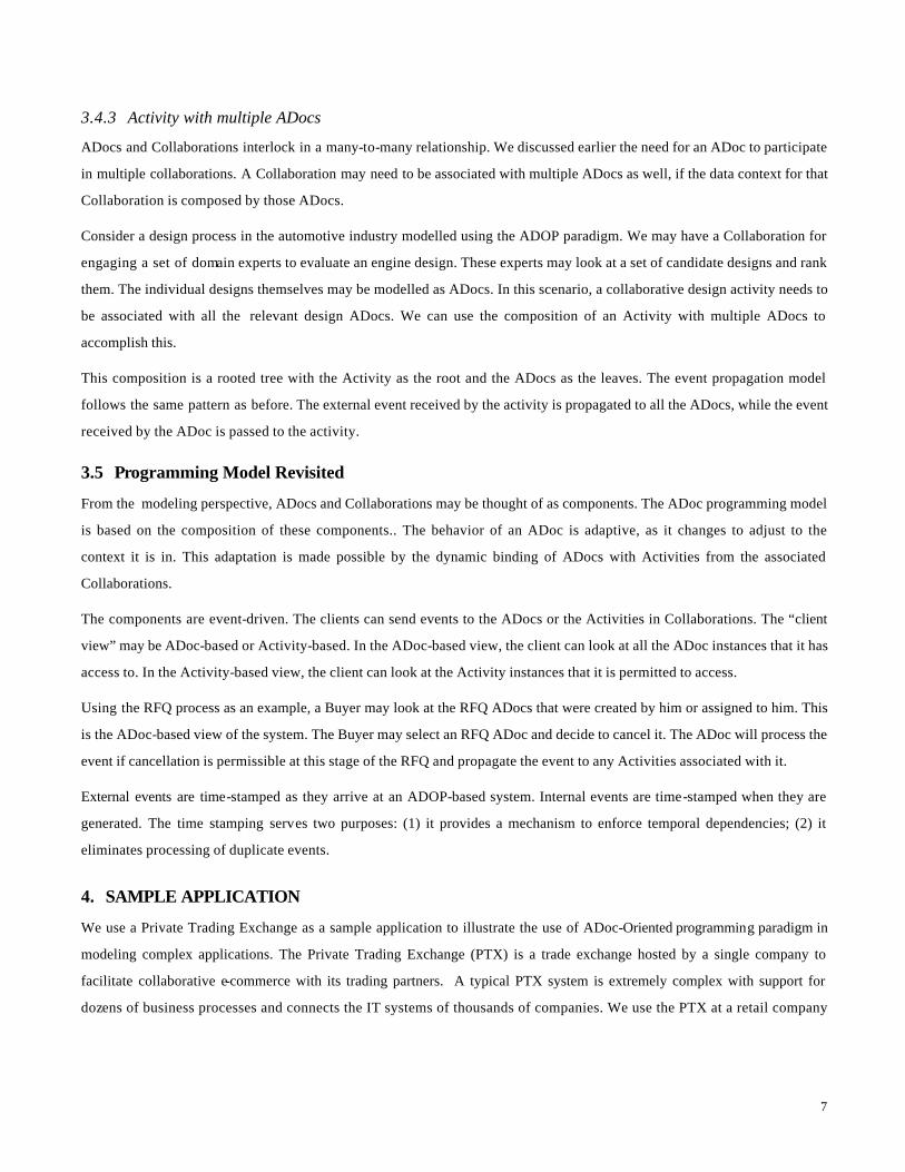
3.4.3 Activity with multiple ADocs
ADocs and Collaborations interlock in a many-to-many relationship. We discussed earlier the need for an ADoc to participate
in multiple collaborations. A Collaboration may need to be associated with multiple ADocs as well, if the data context for that
Collaboration is composed by those ADocs.
Consider a design process in the automotive industry modelled using the ADOP paradigm. We may have a Collaboration for
engaging a set of domain experts to evaluate an engine design. These experts may look at a set of candidate designs and rank
them. The individual designs themselves may be modelled as ADocs. In this scenario, a collaborative design activity needs to
be associated with all the relevant design ADocs. We can use the composition of an Activity with multiple ADocs to
accomplish this.
This composition is a rooted tree with the Activity as the root and the ADocs as the leaves. The event propagation model
follows the same pattern as before. The external event received by the activity is propagated to all the ADocs, while the event
received by the ADoc is passed to the activity.
3.5 Programming Model Revisited
From the modeling perspective, ADocs and Collaborations may be thought of as components. The ADoc programming model
is based on the composition of these components.. The behavior of an ADoc is adaptive, as it changes to adjust to the
context it is in. This adaptation is made possible by the dynamic binding of ADocs with Activities from the associated
Collaborations.
The components are event-driven. The clients can send events to the ADocs or the Activities in Collaborations. The “client
view” may be ADoc-based or Activity-based. In the ADoc-based view, the client can look at all the ADoc instances that it has
access to. In the Activity-based view, the client can look at the Activity instances that it is permitted to access.
Using the RFQ process as an example, a Buyer may look at the RFQ ADocs that were created by him or assigned to him. This
is the ADoc-based view of the system. The Buyer may select an RFQ ADoc and decide to cancel it. The ADoc will process the
event if cancellation is permissible at this stage of the RFQ and propagate the event to any Activities associated with it.
External events are time-stamped as they arrive at an ADOP-based system. Internal events are time-stamped when they are
generated. The time stamping serves two purposes: (1) it provides a mechanism to enforce temporal dependencies; (2) it
eliminates processing of duplicate events.
4. SAMPLE APPLICATION
We use a Private Trading Exchange as a sample application to illustrate the use of ADoc-Oriented programming paradigm in
modeling complex applications. The Private Trading Exchange (PTX) is a trade exchange hosted by a single company to
facilitate collaborative e-commerce with its trading partners. A typical PTX system is extremely complex with support for
dozens of business processes and connects the IT systems of thousands of companies. We use the PTX at a retail company

8
as an example to illustrate the use of ADOP in building complex systems that enable large-scale integration and collaboration
functions.
The scope of the PTX typically includes CPFR (Collaborative Planning Forecasting & Replenishment) [28], RFQ (Request For
Quote), Contract, PO (Purchase Order), ASN (Advanced Shipping Notice) and Delivery processes. Two of these, Contract and
Delivery, are being used in this paper to illustrate the application of ADOP design paradigm.
4.1 Supplier Contract Management
The Contract process deals with the collaboration involving the Retailer and its Suppliers to put a mutually acceptable
contract in place that drive the delivery of goods. It starts with the Retailer generating a Contract using their legacy contract
system and sending that to the Supplier for concurrence. The Supplier could accept it, reject it, or suggest a modification. If
the Supplier modifies the Contract, Retailer can respond by an "accept" or a counter-offer. An "accept" or "reject" by either
party terminates the Collaboration. An "accept" by the parties does not result in an immediate closing of the contract.
Similarly, a “reject” does not cause the immediate cancellation of the contract either. After a mutually agreed grace period
following the accept (or reject), the contract is closed and is binding to both parties (or cancelled resulting in the termination
of business between the parties.) While in the grace period, either party can revoke their decision, leading to a repeat of the
process described above.
The Contract and the associated data is a very important part of modeling the Contract process. The Contract describes the
terms and conditions under which Retailer and the Supplier engage in business, specifically with respect to delivery of goods.
The Contract document specifies these terms and conditions. Additionally, it specifies several other documents that need to
be referenced to correctly understand the Contract. For simplicity, we discuss two such documents here: (1) The Lab Test
Procedures and Test Data that needs to be provided with the shipment of goods (2) The Quality Control process the Retailer
has in place for this Supplier. These are examples of unstructured data associated with the Contract. Additionally, there is
structured data stored in relational databases. These include Contract table, Supplier table, and Product table, to name a few.
For modeling the Contract correctly, we need to capture these dependencies as well. Further, it is important to dynamically
aggregate the content associated with a Contract and present views of this content based on the context in which these views
are used. For example, the view of the Contract presented to the Suppliers for getting their approval may need to display not
merely the terms and conditions of the contract but information on laboratory test requirements and quality control processes
as well. But a view presented to the Retailer in the context of approving a modification suggested by a Supplier may show only
the part of the contract that is being modified.
The life cycle management of a Contract is important from the business perspective. A contract may begin its life as a “draft”
document. Once it is approved, it becomes “active”. If it is rejected by either party, it is said to be “rejected” . After the term of
the contract expires, it is “expired”. A Contract could also be “terminated”, “cancelled”, and “archived”. The set of business
events it can handle depends on the state of the Contract. For example, a Supplier can modify a Contract only when it is in the
“draft” state.

9
4.2 Delivery Management
Next we describe the Delivery process. It has two subprocesses: (1) Shipment Verification (2) QC Booking. The purpose of
Shipment Verification is to get confirmation from the suppliers on the delivery date, vessel, and carrier. This gives the
suppliers an opportunity to notify the retailer on any changes in the previously agreed upon delivery dates. The contract
specifies the time window in which such modifications can be made. A few days before the expiry of the time window, the
suppliers are notified and asked to confirm the delivery date and provide the vessel and carrier information. A request to
change the delivery date needs the approval of the retailer. If the request is not approved by the retailer, the Supplier may
send in a new request. If the two parties are not able to resolve the issue before the expiry of the time window, the original date
in the Purchase Order is binding.
The Shipment Verification process operates on “shipments”. A shipment is a collection of goods shipped by a supplier to the
retailer in one vessel. The goods in a shipment may come from different Purchase Orders, but share a delivery date, vessel
name, and carrier. Figure 2 shows the relationships of Purchase Orders, Shipments, and Contracts. A Contract typically
covers several Purchase Orders. A Purchase Order has multiple line items. Line items from several Purchase Orders could be
bundled into a Shipment.
Typically, a supplier cannot ship goods before they are inspected and certified by a quality control (QC) agent. Some
suppliers are exempt from this requirement. The quality control requirements are outlined in the supplier contract. If QC
inspection is required, then the suppliers may group a set of shipments together and present this group to the QC agent. Such
a group is called a “ Lot”. The QC Booking process deals with the formation of such groups, and the assignment of a QC
inspector and an inspection date to the Lot. Suppliers form the Lot and request the inspection agency to assign an inspector
and a date. Once the supplier and the QC agency have agreed on a date, the information is sent to the Retailer for the final
approval.
Next we discuss the life cycle management of shipments and Lots. As a shipment is created by a Supplier, it has a delivery
date derived from the Purchase Order line items being included in the Shipment. (All line items in a Shipment need to have the
same delivery date.) The Shipment is said to be “open” at this point in time. Any changes to this delivery date or the addition
of vessel and carrier information will result in the retailer being notified. The Shipment is then in “pending approval” mode.
Purchase Orders
Contract
Line Items Shipment
Line Items
Figure 2: Shipment and its dependencies

10
Once the Retailer has approved the date change or the time window for such changes has passed, the Shipment moves to
either “pending QC” or “ready”, depending on whether the QC inspection is required. Shipments that need QC inspection
moves to “ready” if certified by the inspector. If the goods fail the QC inspection, the Shipment us “rejected”. Only shipments
that are “ready” can be shipped, and then it is “in transit”. Once the Retailer receives the goods, the Shipment is said to be
“delivered”.
The Lot has a shorter life cycle. A Lot is created by a supplier and initially it is a “draft”. It becomes “active” once the
inspector and the date are assigned. From there, it could be “rejected” or “approved” based on the results of QC inspection.
Eventually, it is “archived”.
4.3 System Design
In object-oriented programming paradigm, identifying the “objects” is a key part of the design process. Similarly, in ADoc-
oriented programming, the system design revolves around the identification and definition of the ADocs. The key information
artifacts in the target solution domain are modeled as ADocs. In the subset of the PTX problem we discussed above, there are
three such artifacts: (1) Contract (2) Shipment, and (3) Lot. We use them as ADocs in our design.
There are three ADoc compositions possible in the system. A set of Shipment ADocs may be associated with a Contract
ADoc. This association implies that the terms and conditions for the Shipment are dictated by the associated Contract. The
second composition involves a Lot with a set of Shipments. This implies that the Lot is made up of the associated Shipments.
The third involves a Contract with the Lots, implying that Lots are bound by the Contracts as well. Figure 3 shows the ADocs
and their compositions.
Contract 10
Shipment 102
Shipment 104
Shipment 103
Shipment 101
Lot 20 Lot 21
Figure 3: Example of ADoc instances and their compositions
Next we look at the Collaborations in our design. Supplier contract management involves a collaboration between the Retailer
and the Supplier, which we call Supplier Collaboration. This Collaboration binds with the Contract ADoc. The Shipment
Verification process translates to another collaboration between the Retailer and Supplier. This binds with the Shipment
ADoc, as an instance of this collaboration takes place in the context of a Shipment. The third and final collaboration involves
Retailer, Supplier, and the QC Agency. The Lot provides the context for this collaboration. The second and third
Collaborations are called Shipment Verification Collaboration and QC Collaboration respectively. The figure below shows the
ADoc-Collaboration associations. Though this example shows a one-to-one mapping between ADocs and Collaborations,
there could be a many-to-many mapping in general.

11
Contract ADoc
Supplier Contract Collaboration
Lot ADoc
QC Collaboration
Shipment ADoc
Shipment Verif. Collaboration
Figure 4: ADoc-Collaboration associations
In the remainder of this section, we describe the participating ADocs and Collaborations in detail.
4.3.1 ADocs
Definition of an ADoc includes three sections, two of these are required while the third is optional. The required sections are
the Data Context definition and the Behavior definition. The View definition is optional. The Views are used only in systems
that support interactive user experience. Systems where all client interactions are strictly programmatic, Views are not required.
For example, in the PTX application we discussed earlier, a Supplier may interact with the system via a Browser interface in
which case the Views of the ADocs are used for user interaction. Alternatively, computer programs running in the Supplier’s
IT environment could act as user proxies and programmatically exercise PTX functions. In this scenario, ADoc views are not
used. In this paper, we focus on programmatic access of ADoc functions, hence we do not discuss the ADoc views in detail.
4.3.1.1 Contract ADoc
The data context of a Contract ADoc is made up of the following:
q Contract ID and data access commands for retrieving/updating contract data.
q Supplier ID and data access commands for retrieving supplier data from the data stores.
q Lab Test Procedure ID and data access commands for retrieving lab test process documents.
q QC Inspection Process ID and data access commands for retrieving QC inspection process documents.
The ADoc behavior is described using a Finite State Machine. Figure 5 shows the finite state machine of a Contract ADoc.
Initially, when the Contract is created, the Contract ADoc is in DRAFT state. In this state, the Retailer can make as many
modifications as necessary. Once the Retailer submits the Contract for Supplier approval, the ADoc executes a command to
spawn the Supplier Contract Collaboration. The state machine transitions are tagged by the event causing it (Submit, Modify,
etc), the guard condition (User==Retailer), and the Commands executed (Update; Spawn-Collaboration).
From this Collaboration, an “approve”, “reject”, or “modify” event could be propagated to the Contract ADoc. Since there
are events propagated from the Collaboration to the ADoc, these are specified as C::Approve, C::Reject, and C::Modify
respectively in the Finite State Machine. The mechanism for this event propagation was discussed in section 3.4 on Activity-
ADoc compositions. In section 4.4, the dynamic compositions are discussed in detail for this specific scenario.

12
The C::Approve event transitions the Contract ADoc to APPROVED state, while C::Reject event transitions the Contract
ADoc to REJECTED state. Either of these events signals the end of the collaboration. But C::Modify event could occur
multiple times while the collaboration is ongoing. Supplier or Retailer could suggest modifications to the Contract in an infinite
loop.
The grace period starts as soon as the ADoc is in the APPROVED or REJECTED state. The end-of-grace-period signal moves
the ADoc to an ACTIVE or CANCELLED state. From the ACTIVE state, the ADoc could move to EXPIRED state when the
term of the contract expires.
4.3.1.2 Shipment ADoc
The data context of a Shipment ADoc is composed of the following:
q Shipment ID and data access commands to retrieve and update shipment information in the persistent store.
q Purchase Order Line Item Identifiers and data access commands to retrieve Line Item data from the enterprise
information system that stores Purchase Orders.
When a shipment is first created by the Supplier, the corresponding ADoc is created and it is in the OPEN state. In this state,
the Supplier can modify the delivery date if necessary. If they modified the date, they submit it for Retailer approval. This
event, called “Request-Sate-Change” causes the ADoc to spawn QC Collaboration. The QC-Booked event transforms the
state from OPEN to PENDING-QC. If QC inspection is not required, a “Ready” event from the manufacturing floor changes the
state of the Shipment to READY. If QC inspection is required, the Shipment reaches READY state when “QC Pass” event is
received.
4.3.1.3 Lot ADoc
The data context of the Lot ADoc consists of a Lot ID and the data access commands for reading and updating Lot data from
the data store. Date-Request event causes the ADoc to spawn the QC Collaboration. The Date-Entry event changes the state to ACTIVE.
Depending on the result of QC inspection, the state then changes to REJECTED or APPROVED.
4.3.2 Collaborations
There are three parts to defining a Collaboration: (1) The participating Agents (2) The definition of its Activity Choreography
mechanism, and (3) The definition of the Activities.
The activity choreography is used to identify the set of activities associated with a Collaboration and the order in which these
Activities are executed. There are three ways this could be accomplished:
1. The Activities may be associated with a Collaboration in an ad hoc manner while the system is running. The client
programs may use the Collaboration APIs to add Activities.
2. The set of activities and the order in which they are executed are defined a priori. There are different representation
schemes for defining this. A commonly used mechanism is a directed graph, where the nodes are the Activities and the
arcs represent the dependencies between them. This is the approach taken in the control flow of workflow graph [8].

13
3. A hybrid approach may be employed in which the set of Activities are predefined, but not the order of execution. At
runtime, an inference engine analyzes the context and determines the order of execution.
In this paper, we focus on the second activity choreography mechanism in the list above.
An Activity is defined using the Finite State Machine controlling it. Each Activity is associated with a set of Agents that can
act on it. The default Finite State Machine of an Activity is presented in section 3.3. For the Activities used in the sample
application, we discuss below how the default behavior is extended for customization.
APPROVED
REJECTED
ACTIVE
CANCELLED
EXPIRED
ARCHIVED
DRAFT
End-of-Grace-Period Signal[ None ] / Update; Notify
Term-Expiry Signal[ None ] / Update; Notify
Archival Signal[ None ] / Archive; Purge
C::Modify[ None ] / Update
End-of-Grace-Period Signal[ None ] / Update; Notify; Schedule Term Expiry Signal
Submit[ User==Retailer ] / Update; Spawn-Collaboration
C::Reject[ None ] / Update Contract DB; Notify; Schedule Grace Period
C::Approve[ None ] / Update Contract DB; Notify; Schedule Grace Period
Figure 5: Finite State Machine for Contract ADoc
We discuss the details of the Supplier Contract Collaboration below. The Agent set associated with this Collaboration is
{Supplier, Retailer}. There are two activities in this collaboration, one assigned to the Supplier and the other to the Retailer.
The activities are S-Disposal and R-Disposal. The directed graph for activity choreography is shown in the figure below.
Both FSMs have similar structure and extends the default behavior to support “Modify”, “Approve”, and “Reject” as valid
events that trigger the state change from CLAIMED to COMPLETED. Since these activity instances are dynamically bound to
the Contract ADoc instance in an ADoc-Activity composition, these events are propagated to the ADoc from the Activity.
Processing of these events by the ADoc controller is discussed in section 4.3.1.1. The behavior of the system as it executes
Supplier Contract Management Process is discussed in detail in section 4.4.

14
S-Disposal R-Disposal
Start
Initiator?
Spawn[ Initiator==Retailer ]Spawn[ Initiator==Supplier ]
End
Approve or RejectApprove or Reject
Modify Modify
RetailerSupplier PASSIVE
AVAILABLE
CLAIMED
COMPLETED
Activate
Claim[ USER==Supplier ] / Claim-Command
Approve[ (USER==Claimed User) ] / Complete-Command
Reject[ USER==Claimed User ] / Complete-Command
Modify[ USER==Claimed User ] / Complete-Command
Figure 6: Activity Choreography for Supplier Contract Collaboration and the Activity Controller for S-Disposal Activity
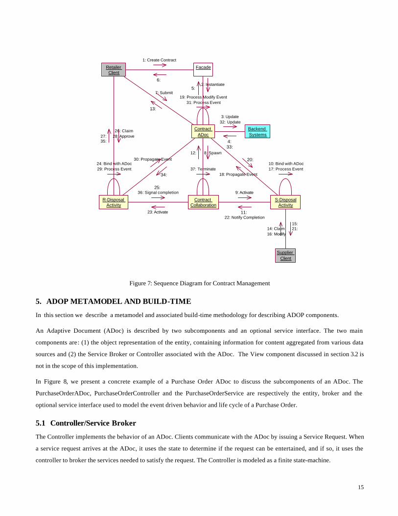
4.4 Putting It All Together
We discuss the behavior of the PTX system as it executes the Contract Management Process in detail in this section. At
build-time, the three ADocs (Contract, Shipment, and Lot), the three Collaborations (Supplier Contract, Shipment Verification,
and QC), all the Commands used by the ADocs and Collaboration Activities, and the Receivers invoked by these Commands
are described. These descriptions are in a scripting language based on XML. The details of this language are discussed in
section 5.1. At startup, the runtime reads in all these descriptions and configures the PTX application. We present a step-by-
step description of a scenario for Supplier Contract Management in Figure 7.
Steps 1 through 6 show the system response to a Retailer Client creating a new Supplier Contract. At the point in time, PTX is
populated with a Contract ADoc in DRAFT state.
Steps 7 through 13 show the system behavior in response to the submission of the Contract by Retailer for Supplier approval.
This results in an S-Disposal Activity in AVAILABLE state to be bound to the Contract ADoc.
In steps 14 through 25, Supplier claims the activity, and then proposes a modification to the Retailer. In response, S-Disposal
Activity runs to completion and the R-Disposal Activity is made available to the Retailer. This Activity is in AVAILABLE
state and bound to the Contract ADoc. Steps 26 through 37 show how system reacts to the Retailer accepting the
modification. The R-Disposal Activity runs to completion, and the state of the Contract ADoc moves to APPROVED.
It should be noted that real world PTX systems include a lot more details than the one we presented here. We have eliminated
these details for better utilization of the limited space.
15
Retailer Client
Facade
Contract ADoc
Backend Systems
Contract Collaboration
S-DisposalActivity
R-Disposal Activity
Supplier Client
10: Bind with ADoc17: Process Event
19: Process Modify Event
24: Bind with ADoc29: Process Event
31: Process Event
37: Terminate
1: Create Contract
6:
7: Submit
13:
26: Claim28: Approve27:
35:
2: Instantiate5:
3: Update32: Update
4: 33:
8: Spawn12:
9: Activate
11: 22: Notify Completion
23: Activate
25: 36: Signal completion
18: Propagate Event
20: 30: Propagate Event
34:
14: Claim16: Modify
15: 21:
Figure 7: Sequence Diagram for Contract Management
5. ADOP METAMODEL AND BUILD-TIME
In this section we describe a metamodel and associated build-time methodology for describing ADOP components.
An Adaptive Document (ADoc) is described by two subcomponents and an optional service interface. The two main
components are: (1) the object representation of the entity, containing information for content aggregated from various data
sources and (2) the Service Broker or Controller associated with the ADoc. The View component discussed in section 3.2 is
not in the scope of this implementation.
In Figure 8, we present a concrete example of a Purchase Order ADoc to discuss the subcomponents of an ADoc. The
PurchaseOrderADoc, PurchaseOrderController and the PurchaseOrderService are respectively the entity, broker and the
optional service interface used to model the event driven behavior and life cycle of a Purchase Order.
5.1 Controller/Service Broker
The Controller implements the behavior of an ADoc. Clients communicate with the ADoc by issuing a Service Request. When
a service request arrives at the ADoc, it uses the state to determine if the request can be entertained, and if so, it uses the
controller to broker the services needed to satisfy the request. The Controller is modeled as a finite state-machine.

16
AdocBean
getAdocId()getAdocState()getAdocType()getAdocOwner()getAdocParent()getChildAdocs()serviceEvent()
<<CMP EJB>>
AdocProxy
getBaseAdoc()
<<abstract>>
Part Of The Framework
Data
Applications
Collaborations
PurchaseOrderController<<StateMachine>>
manipulate
transact
manage
Client
PurchaseOrderAdoc
getPurchaseOrderId()
<<CMP EJB>>broker
PurchaseOrderService
createPO()validatePO()approvePO()rejectPO()cancelPO()dispatchPO()query()
<<Session EJB>>
event
provides and maintainscontext for the Controller
Figure 8: Purchase Order ADoc
An instance of an ADoc moves from its starting state, through intermediate states to a completion state during its lifetime.
These state changes (transitions) are triggered either through service requests (events) directed to the ADoc component or
method calls on the optional service interface. In the latter case, the service interface will send the appropriate event to the
ADoc component.
Each state within the state machine has a set of transitions to other states. The selection of a particular transition is based on
the identity of the caller, the type of event raised (based on which method was called) and whether a condition has been
satisfied. In this respect, the State Machine is essentially a subset of the UML State Machine definition.
Each transition may have one or more actions associated with it. An action provides the abstraction to access various
systems participating in the process. Relational data sources, business objects, collaboration components (like workflows) or
connectors to enterprise information system are examples of components that can be represented via the action abstraction.
The state transitions are transactional. All the actions that are triggered by a service request are completed within the same
logical unit of work. The ADoc moves to the target state on successful completion of the actions. Incase of a failure, the state
change will not occur and if necessary, recovery procedures such as compensation actions will be executed.
The Controller is specified using the XML Schema shown in Figure 9. An XML file consistent with this schema is generated
by the ADOP tooling. The runtime reads this XML file at system startup and configures the system.

17
state-machine state
name
name
type
timeout
transition event
condition
target-state
action
1..n
0..n
0..n
State Type
Transition Type
Figure 9: ADoc Controller Schema
'Received
Approved
BackOrdered
Packaged
Finished
CreatePO / spawn("CreatePOFlow")
Dispatched
ReceiptAcknowledged
Allocated'Rejected
'Cancelled
Dispatch
CancelPO / terminate("CreatePOFlow");
spawn ("CancelPOFlow")
'Validated
PackageCancelPO / Terminate
("CreatePOFlow")
Cance lPO / te rmina te ( "Crea tePOFlow
");spawn("CancelPOFlow")
Allocate Stock
Approve
Not Approved
NotA l l InS tock
C a n c e l P O / terminate("CreatePOFlow") ;
spawn("Cance lPOFlow")
Allocate Stock
Not in S tock
Anywhere
C a n c e l P O / terminate("CreatePOFlow") ;
spawn("CancelPOFlow")
Invalid Data
Validate
Figure 10: State Machine for PO ADoc Controller
Figure 10 shows the state machine for a Purchase Order (PO) ADoc. When the PO ADoc is created, it is in the “Received”
state. After creation and entering the initial state, the PO ADoc reacts to business events by transitions to other states, until it
reaches the terminal state (Finished). Each transition is triggered by a named event and executes one or more actions before
entering the target state. For example, the PO ADoc moves from the “Approved” to the “Cancelled” state on the ‘Cancel PO’
event. Two actions are performed during this transition. The first action terminates the ‘Create PO’ collaboration (modeled as a

18
workflow) that was spawned on an earlier transition. The second action spawns a new collaboration that handles the
cancellation of the PO with the concerned agents being assigned activities to act on the cancellation process.
Actions are modeled using the Command and Composite design pattern [18]. Using the composite design pattern, shown in
Figure 11, it is possible to compose commands to form composite-commands or micro-flows. The commands are specified
using XML. The XML command schema is shown in Figure 12.
<<interface>>Command
<<micro -flow>>CompositeCommand
BasicCommand
Figure 11: Composite Command
Each command has zero or more input parameters and returns an output. Both input and output data structures are specified
as a name-value pair. The command is identified by its method name. The commands executed within a state transition are in a
single unit of work. In the event of a transaction failure, the actions executed by the commands are undone using the undo
commands. Some of the end points that are engaged may not be transactional systems and recovery entails using
compensation logic. Such logic can be encapsulated in the undo commands.
command input
output
method name
name
1..n 0..n value
receiver id
command id
undo command0..n
commandlist
name
value
Figure 12: Command Schema
The receiver associated with a command is identified by the receiverId. The receiver is an interface to the service providers,
i.e., implementations of the business logic expressed in the commands. This level of indirection provides by the receivers
enables the dynamic mapping of the service providers to the commands.

19
There can be many types of receivers such as a JMS (Java Message Service) [20] receiver for asynchronous connectivity to
various back-end applications and systems or RMI, EJB (RMI-IIOP), CORBA (IIOP) [20] receivers for synchronous
connectivity to business objects and enterprise applications. Cross enterprise integration may be modeled by specifying
externally exposed services as Web Service receivers, although Web Services may be used for intra-enterprise integration as
well.
Object-based interfaces, whether local (same JVM) or distributed (RMI, EJB, CORBA, Web Services), are easily mapped to the
command-receiver paradigm. For the non-object based protocols (JMS, JCA, JDBC etc.), Java wrappers are provided as part of
the runtime. The receivers are specified using XML as well. The structure of the receiver is shown in Figure 13. (Notice that
the schema shows protocol bindings for EJB and Java only).
Receiver protocol
1..n
receiver id
0..n
receiverlist
ejb
local | remote
jndi name
implementationclass
home class
java class name
name
value
constructorparameters
corba
web service
Figure 13: Receiver Schema
5.2 Service Interface
The service interface (PurchaseOrderService in Figure 8) acts as a façade and a single point of entry for clients. More
importantly, the methods on the service provide a strongly typed interface for clients to pass event parameters. The service
interface is typically generated by tooling and fits the J2EE programming model [20]. It implements the notion of a Message
Driven Bean (MDB) to support asynchronous or message-based clients communicating via the Java Messaging Service
(JMS).
Calls to the service interface can be categorized into 3 types; (a) methods to manage the life cycle of ADocs (create, remove,
archive) (b) solution specific methods for clients to send business events to particular ADoc instances and (c) query
interfaces to inquire the status of a single or group of ADocs.
Access to the service interface methods would normally be restricted based on the identity of the client (program or human)
interacting with the system. For example, only the Administrator is allowed access to the CancelPO method.

20
5.3 Entity
The ADoc entity holds the state information of the ADoc instance. It also provides the appropriate context and acts as an
editable resource folder to the Controller and the services it brokers. It is modeled as a CMP (Container Managed Persistence)
EJB and support for transactions and transactional isolation, thread-management and security are automatically provided by
the EJB container.
The ADoc entity is composed of a base part and a solution part. The base part is a system component. It persists the common
attributes for the ADoc, such as state, owner, type of controller, and relations to other ADocs. It is also responsible for
instantiating the Controller object and passing client service requests to the Controller object for execution.
The role of the solution part of the ADoc is to hold domain-specific content. It extends the base and acts mostly as a container
for aggregated data references. The Solution part of the ADoc entity is implemented as a Container-Managed EJB as well.
5.4 Putting It All Together
To summarize, building an ADoc component comprises of the following steps:
o Generate the Solution ADoc entity EJB (for example, PurchaseOrderADoc)
o Generate the Controller XML file containing the state machinedescription (for example, POADocController.xml)
o Register Receivers in the receiver registry (for example, by specifying the receivers in a “Receiver.XML” file).
o Register Commands in the command registry (for example, by specifying the commands in a “Commands.XML” file).
o Generate the service interface (for example, PurchaseOrderService).
6. ANALYSIS OF ADOC-ORIENTED PROGRAMMING
This section presents an analysis of ADoc-Oriented programming approach. We begin with the unique features and strengths
of this approach, discuss the opportunities, and conclude the section with a discussion of our experience in using this system
in customer engagements.
6.1 Strengths of ADOP Approach
Below we list the unique features and strengths of ADOP:
o ADOP provides an Object-Oriented solution for business process management. The prior work in business process
management has focused heavily on flow models [7],[8],[9],[11],[12]. Even the work specifically targeted to build OO
systems [10] has managed only to create a façade for flow control engines.
o ADOP supports modeling of distributed BPM applications. Truly distributed BPM applications are inherently
autonomous. An excellent example is Business-to-Business integration, where multiple businesses integrate their IT
systems to execute cross-enterprise business processes [27]. The notion of a “conversation” is the key to modeling
such integration scenarios. ADocs may be used to model the exchange of multiple correlated messages with arbitrary
sequencing constraints that form a conversation [14].

21
o ADocs are inherently scalable. Most business systems are embarrassingly parallel. ADOP based systems exploit this
by associating a thread of control with every instance of a business document. All transactions on that business
document are routed to this control thread, which is implemented as an ADoc Controller. The ADoc instances can be
distributed in a network of machines. As the number of business documents increases, performance levels can be
maintained by adding more nodes to the network [15],[16].
o ADOP reduces software complexity via orthogonal decomposition of solution space. Well-designed OO systems
reduce software complexity by enabling the modeling of the application space by orthogonal class families. This
leads to the realization of rich application functionality by composing object instances from these class families. In
ADoc-based systems, we observe the same feature, as ADocs and Collaborations are orthogonal modeling elements.
Compositions of ADocs and Collaborations lead to powerful, yet simple, BPM solutions.
o ADocs support a solution assembly paradigm and facilitates the realization of new functionality from existing
components. The ADoc controller state machine serves up new business behavior while the legacy systems are
utilized in providing pieces of the new functionality. The controller uses Command design pattern [18] to bind
abstract actions to specific receivers, which in this case are the APIs of the legacy systems. In most cases, syntactic
and semantic adaptation is necessary for this to work [17]. Java Connectivity Architecture provides a standards-
based technology to build such adapters [20]. ADocs serve as the glue that brings together all the components of a
BPM solution, leading to the definition and implementation of reusable solution templates.
o ADocs support event-driven programming. A façade object routes the external events to the appropriate ADoc or
Activity. An ADoc may propagate this event to other ADocs or Activities if it is part of a composition. Similarly, an
Activity may propagate the event to associated ADocs.
o ADOP provides a unified model for integration and Collaboration. The ability of this system to present a unified
model for integration and collaboration stems from the composition of ADocs and Activities.
o ADOP brings together information integration and process integration. Traditionally, information integration and
process integration has been treated in isolation. In reality, these are merely different aspects of the integration
problem. In ADoc-Oriented programming, we present a model that supports both. From the information integration
perspective, ADocs provide a way to dynamically aggregate content that is fractured and distributed. One could
think of an ADoc as a virtual business artifact that provide context -specific views by aggregating content on
demand. Additionally, by modeling the application state and the process state and tying that together with the
content aggregation function, we present an approach to integration that subsumes process integration and
information integration. A specific data integration technology, such as data federation, could still be used in the
context of the data aggregation function of the ADoc.
o ADOP provides native support for collaboration. There are several models of collaboration, examples include
workflow collaboration, real-time collaboration, peer-to-peer and multiparty conversations, and team rooms. In ADOP,
the notion of a Collaboration object is used to model the collaborative activities, with the ability to create various

22
types of collaboration by specifying an appropriate Activity Choreography mechanism and composing the
Collaboration instance using that.
o ADOP supports Process Brokering. Non-trivial BPM systems have several processes that are concurrently active
and manipulate shared business data. A business event, external or internal, could impact several of these processes
and modify business data distributed across the enterprise. Consider a supply chain management application hosted
by a large manufacturing company. The cancellation of a Purchase Order by a customer may impact the logistics
processes, CPFR (Collaborative Planning, Forecast, and Replenishment) processes [28], and financial processes.
There is a requirement to “broker” the event, such that the event can be propagated to the appropriate processes and
business components. This event propagation is dependent on the application state. The ADoc instances in a BPM
application serve as a distributed process broker. The event is routed to the appropriate ADoc instance. The ADoc
instance processes the event based on its current state and the contents of the event, then propagates the event to
other ADocs or Activities based on the compositions it is part of. The commands that are executed as part of this
event processing could map to method invocations on enterprise information systems, notifications to enterprise
users, creation of new ADocs and Collaborations, termination of existing Collaborations, etc.
o The notion of “ADoc views” supports a RAD environment for interactive business process management
applications. These views are defined as part of an ADoc and are adapted based on the “context” in which it is
looked at. The context could include the role of the user, the state of the ADoc, the Activities associated with the
ADoc, and the states of these Activities. The views represent only the information to be presented, the data to be
garnered, and the set of available actions. The rendering of these views is decoupled from the view definition. The
views are defined using XML and the rendering is specified using XSL.
o ADocs provide the right granularity for server side componetization. One could visualize a solution assembly
paradigm in which ADocs are retrieved from a repository, configured appropriately, and bound to the “environment”
to realize BPM solutions. This vision becomes all the more powerful when universally accepted standards emerge for
specification and runtime support of ADOP artifacts.
o ADOP facilitates externalization of “wiring” logic. The XML files that describe the ADoc and Activity controllers, the
command XML files, and the receiver XML files together encapsulate macro level system behavior. This logic can be
easily modified, even programmatically, leading to adaptive and dynamic systems.
6.2 Validation in the Marketplace
The technology discussed in this paper has been validated extensively in the marketplace via customer engagements as part
of a core component of an eBusiness Platform for Integration and Collaboration [21]. These customer engagements have
paved the way for the technology to evolve to its present form, our ideas to crystallize, and the strengths discussed above to
surface. We list below some of these validation points:

23
o A Virtual Corporation Management System in which multiple companies dynamically form virtual coalitions to serve
specific customer opportunities. The coalitions disband once the service has been delivered and all the associated
processes are completed [19].
o A Web-based supply chain management system for a distributor in retail industry to integrate their partner systems
with their enterprise systems.
o A procurement portal for a large manufacturer to connect their suppliers with internal business processes.
o A Private Trading Exchange for a large automobile manufacturer [27].
o A public eMarket for retail industry.
o A supply chain management system for a diversified heavy equipment manufacturer.
o A collaborative product lifecycle management application [29].
o Straight Through Processing for financial industry.
7. RELATED WORK
The UML (Unified Modeling Language) state machines [23] are used extensively in object oriented analysis. We use a subset
of UML state machine to define the ADoc and Activity controllers. From the ADoc-oriented programming perspective, a finite
state machine is merely one of the ways to define a controller. For instance, a rule engine [25] could be used for
choreographing the controllers in place of the finite state machine. While deterministic finite state machines have the benefit
of predictable behavior, they define “closed” systems and may not be suitable for modeling emergent phenomena. Rule-based
ADocs may be better equipped to model such behavior. In any case, it is important to realize that crux of our approach is not
the use of finite state machines, but the modeling of the solution space via business artifacts and collaborations and their
compositions.
Harel and Polity [22] discuss modeling of reactive systems with statecharts. They use statecharts and activity charts to
develop a conceptual model of the system. Harel’s statecharts are a generalization of the UML state machine [26], while the
activity chart describes the system activities and the data that flows between them. The statecharts present the behavioral
view while the activity charts present the functional view of the system. In contrast, the power of the ADOP approach is in the
modeling of the system behavior via compositions of ADocs and Collaborations.
The design patterns [18] have influenced our work in many ways. In particular, the Command design pattern, the Composite
design pattern, and the Façade design pattern are heavily used in designing the system.
Most work in business process management has focused on flow models [9],[11],[25]. While flow models have an important
role to play, they are not sufficient to model BPM solutions for the enterprise. The shortcomings of the flow models in
modeling non-trivial BPM applications are discussed in detail in [12]. In this paper, we have presented a modeling approach
that is based on OO principles, while leveraging the flow models as appropriate.

24
8. CONCLUSION
Enterprise computing landscape is evolving in various dimensions. There is increased focus on solution assembly as opposed
to solution development. There is an emphasis on integrated solutions, as opposed to functional silos. It is not enough to
have multi-user environments, but collaborative systems that facilitate enterprise collaboration among an online community of
users is the norm.
In this paper, we introduced the notion of an ADoc as a higher level modeling artifact, formalized collaborations, and showed
how compositions of ADocs and Collaborations can serve as a powerful tool to model enterprise applications that focus on
business process management, integration, and collaboration.
9. REFERENCES
[1] Ross Altman, “Total Business Integration, Strategy & Tactics/Trends & Direction,” Gartner Reports, February, 2001
[2] David McCoy, Jess Thompson, “Application Integration Thriving Among Standards, Strategy & Tactics/Trends & Direction,”
Gartner Reports, July, 2001
[3] Joanne Correia, “Looking Forward to 2005 in the AIM Market, Strategy & Tactics/Trends & Direction,” Gartner Reports, July, 2001
[4] Joanne Correia, “What's Happening in the Infrastructure Software Market, Strategy & Tactics/Trends & Direction,” Gartner Reports,
August, 2001
[5] Roy Schulte, Ross Altman, “Application Integration: Success Amid Turmoil, Strategy & Tactics/Trends & Direction,” Gartner
Reports, August, 2001
[6] Roy Schulte Ross Altman, “Integration Middleware Vendors Mix and Match Functionality, Strategy & Tactics/Trends & Direction,”
Gartner Reports, August, 2001.
[7] F. Leymann, and D. Roller, “Workflow-based Applications,” IBM Systems Journal, vol 36, no 1, 1997, 102-123.
[8] F. Leymann, “Web Services Flow language”, IBM, http://www.ibm.com/software/solutions/webservices/pdf/WSFL.pdf
[9] BPMI.org. “Business Process Modeling Language”, http://www.bpmi.org/bpml.esp
[10] Schulze W., "Fitting the Workflow Management Facility into the Object Management Architecture", Workshop on Business Object
Design and Implementation III, OOPSLA, 1997
[11] Thatte, S. XLANG: Web Services for Business Process Design. Microsoft Corporation, 2001.
[12] D. Georgakopoulos, H. Schuster, A. Cichocki, and D. Baker, “Managing Process and Service Fusion in Virtual Enterprises,”
Information Systems, Vol. 24, No. 6, 1999, 429-456
[13] McGregor, C., Kumaran, S. An Agent-Based System for Trading Partner Management in B2B e-Commerce, Proceedings of RIDE
2002, San Jose, CA.
[14] Hanson, J., Nandi, P., Kumaran, S. Conversation Support for Business Process Integration. Submitted to EDOC 2002.

25
[15] Liu, T., Kumaran, S. Layered Queuing Models for Enterprise Javabean Applications. Proceedings of the Enterprise Distributed
Objects Computing Conference, 2001, Seattle WA.
[16] Liu, T., Kumaran, S. Enterprise JavaBean Response Time Analysis. Proceedings of CMG, 2001, San Jose, CA.
[17] IBM WebSphere Business Integrator, IBM Corporation,
http://gwareview.software.ibm.com/software/webservers/btobintegrator/library.html
[18] E. Gamma, R. Helm, R. Johnson, J. Vlissides, “Design Patterns – Elements of Reusable Object Oriented Software,” Addison-Wesley
Publishing Company, NY, 1995.
[19] Nayak, N.; Bhaskaran, K.; Das, R., “Virtual enterprises-building blocks for dynamic e-business,” Proceedings of the Workshop on
Information Technology for Virtual Enterprises, 2001. Page(s): 80 –87
[20] Java 2 Platform Enterprise Edition (J2EE), Platform specification, version 1.3.
http://java.sun.com/j2ee/.
[21] Bhaskaran, K., Kumaran, S., Nandi, P., Das, R., Heath, T., Chung, J-Y. An e-Business Integration & Collaboration Platform for B2B e-
Commerce. In the Proceedings of WECWIS, 2001, San Jose, CA.
[22] Harel, D., Politi, M. The Statemate Approach: Modeling Reactive Systems with Statecharts. McGraw-Hill, 1998.
[23] Rational Corporation. Documents on UML.
http://www.rational.com/uml.
[24] Grosof, B. N., Labrou, Y., Chan, H. Y., A Declarative Approach to Business Rules in Contracts: Courteous Logic Programs in XML.
Proceedings of the first ACM Conference on Electronic Commerce. 1999. Denver, CO.
[25] Nguyen, T.N., “Modeling EAI-based e-business solutions,” IEEE International Conference on Systems, Man, and Cybernetics, 2000,
Page(s): 286 –291.
[26] Harel, D. Statecharts: A Visual Formalism for Complex Systems. Science of Computer Programming, 8, 1987.
[27] Kumaran, S., Huang, Y., Chung, J-Y. A Framework-based Approach to Building Private Trading Exchanges. IBM Systems Journal (To
Appear in June 2002).
[28] VICS Committee “Collaborative Planning, Forecasting and Replenishment Voluntary Guidelines”, June, 1998.
[29] Kumaran, S. Collaborative PLM. IBM Technical Report, 2001.
[30] T. Budd. An Introduction to Object-Oriented Programming. Addison-Wesley, 1991.
[31] WebSphere Application Server, IBM Corporation, http://www.ibm.com/software/webservers/.
[32] Process Broker Services Concepts Guide, ftp://ftp.software.ibm.com/software/btobintegrator/bizaam00.pdf