
Advances in FEFLO
16
-
Upload
independent -
Category
Documents
-
view
2 -
download
0
Transcript of Advances in FEFLO

AIAA-02-1024
ADVANCES IN FEFLO
Rainald L�ohner1, Chi Yang1, Juan Cebral1, Orlando Soto1, Fernando Camelli1,
Joseph D. Baum2, Hong Luo2, Eric Mestreau2, Dmitri Sharov2
1School of Computational SciencesM.S. 4C7, George Mason University, Fairfax, VA 22030-4444, USA
2Applied Physics OperationsScience Applications International Corp., McLean, VA 22102, USA
ABSTRACT
This paper summarizes the major improvements and developments that have taken place during the lastyear for FEFLO, a general-purpose CFD code based on adaptive, unstructured grids. All aspects of acomprehensive CFD capability: gridding, solvers, mesh movement techniques, e�ective use of supercomputerarchitectures and design saw important advances, and are treated.
1. INTRODUCTION
FEFLO was conceived as a general-purpose CFD codebased on the following general principles:
- Use of unstructured grids (automatic grid gener-ation and mesh re�nement);
- Finite element discretization of space;- Separate ow modules for compressible and in-compressible ows;
- ALE formulation for moving grids;- Edge-based data structures for speed;- Optimal data structures for di�erent architec-tures;
- Bottom-up coding from the subroutine level toassure an open-ended, expandable architecture.
The code has had a long history of relevant applica-tions [Bau91, Bau93, Ram93, Bau94, Luo94, Bau95,Bau96, Bau97, Luo98, Bau99, Luo99, Ram99, Bau00,Luo00, Bau01, L�oh01]. During the second half of the1990's, FEFLO has been ported to both shared mem-ory [L�oh98, Tus98, Sha00] and distributed memory[Ram93, L�oh95, Ram96] machines.
This paper summarizes the major developments thathave taken place during the year 2001 for FEFLO.The topics covered include:
- Pre-Processing:- Boolean operations of discrete surfaces;
- Grid generation:- Advances in the gridding of surfaces givenas discrete data;
- Improvements in RANS gridding;- Incompressible solver modules:
- Inclusion of vorticity con�nement to trackvortices over large distances;
Copyright c 2002 by the authors. Published by theAIAA with permission.
- Combination of Baldwin-Lomax andSmagorinsky turbulence models;
- Compressible solver modules:- Arbitrary-gas equation of state lookup;- Combustion modeling;
- Body/mesh movement modules:- Local remeshing for simulations with topol-ogy change; and
- Embedded grids for complex uid-structureinteraction applications;
- Supercomputing:- Porting to OpenMP;- Porting to NEC-SX5;- New renumbering techniques to minimize in-direct addressing;
- Design:- Approximate mixed adjoint formulation;- Pseudo-shell formulation for smooth surfacedeformation; and
- Mesh movement procedure for RANS grids.
2. PRE-PROCESSING
2.1 Boolean Operations of Discrete Surfaces
The rapid, user-friendly de�nition of CFD surfaceshas been an important goal during the last decade.CFD surfaces can be de�ned either analytically (us-ing B-Splines, NURBS, Coon's patches, etc.) or viatriangulations. The latter option is particularly in-teresting for data sets stemming from remote sens-ing data (e.g. geographical data) or medical imaging.An interesting observation made over the last years isthat an increasing number of data sets used to de�nethe geometry of CFD domains is given in the formof triangulations, even though the CAD data is avail-able. The reason for this shift in data type is that awatertight triangulation de�nes in a unique way thedomain considered, and does not require any futher
1

AIAA-02-1024
geometric cleanup operations. This is not the casewith native CAD datasets, in which we frequentlyencounter very large numbers of patches, overlappingpatches, gaps, and other geometric pathologies thatrequire user intervention. The use of triangulations asa means to de�ne geometry immediately implies thenecessity to perform Boolean operations (e.g. union,intersection, subtraction, etc.) on such data sets. In a�rst attempt, a direct geometric intersection of trian-gulations was performed [Sho99]. The resulting tri-angulations exhibited highly deformed elements. Amore elegant way, based on the isodistance concept,was subsequently tried and found to be far superior[Ceb01, Ceb02].
a) b)
c) d)
Figure 1 Measuring Distance to Surface
The idea is illustrated in Figure 1. Given nt tri-angulations, a background grid is built that coverscompletely the region occupied by the triangulations.This background grid may subsequently be adaptivelyre�ned close to the triangulations to improve spatialresolution. In order to capture very small objectsand edges, additional background grid points are in-troduced using a Delauney-based procedure [Geo98].For each triangulation, the closest signed distance toa face is computed for each point of the backgroundgrid. Given these distances, the isosurface of distancezero can be evaluated for the desired Boolean oper-ation. Figure 2 shows the merging of several trian-gulations de�ning buildings and a grid terrain. Thesuperposition of the terrain and building triangula-tions may be seen in Figure 2a. The resulting iso-distance zero triangulation, shown in Figure 2b, wasthen used to generate the surface triangulation of amesh of approximately 900K tetrahedra (Figure 2c)that was used for a ow simulation (Figure 2d). For
more details on Boolean operations for discrete sur-faces, see [Ceb01, Ceb02].
Figure 2a Discrete Data Before Surface Merging
Figure 2b Discrete Data After Surface Merging
Figure 2c Surface Mesh for CFD Simulation
2
AIAA-02-1024
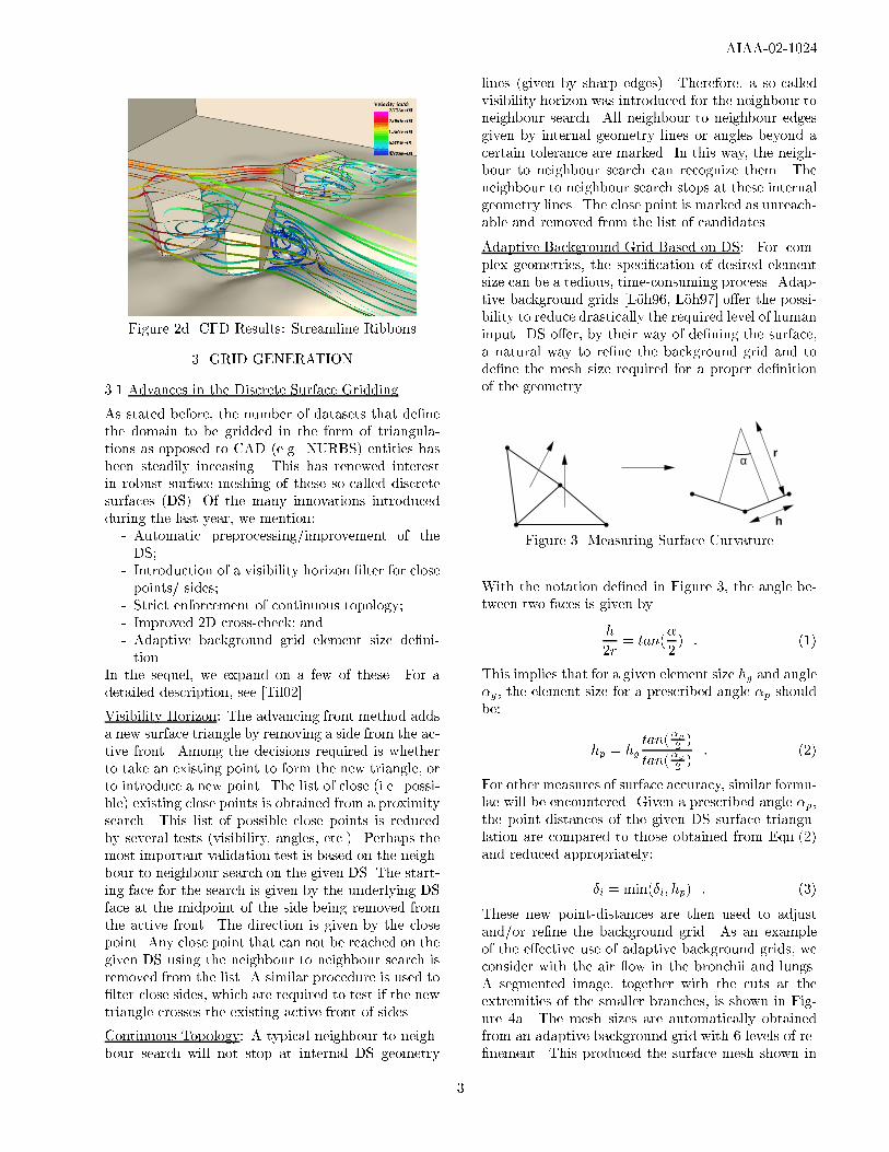
Figure 2d CFD Results: Streamline Ribbons
3. GRID GENERATION
3.1 Advances in the Discrete Surface Gridding
As stated before, the number of datasets that de�nethe domain to be gridded in the form of triangula-tions as opposed to CAD (e.g. NURBS) entities hasbeen steadily inceasing. This has renewed interestin robust surface meshing of these so-called discretesurfaces (DS). Of the many innovations introducedduring the last year, we mention:
- Automatic preprocessing/improvement of theDS;
- Introduction of a visibility horizon �lter for closepoints/ sides;
- Strict enforcement of continuous topology;- Improved 2D cross-check; and- Adaptive background grid element size de�ni-tion.
In the sequel, we expand on a few of these. For adetailed description, see [Til02].
Visibility Horizon: The advancing front method addsa new surface triangle by removing a side from the ac-tive front. Among the decisions required is whetherto take an existing point to form the new triangle, orto introduce a new point. The list of close (i.e. possi-ble) existing close points is obtained from a proximitysearch. This list of possible close points is reducedby several tests (visibility, angles, etc.). Perhaps themost important validation test is based on the neigh-bour to neighbour search on the given DS. The start-ing face for the search is given by the underlying DSface at the midpoint of the side being removed fromthe active front. The direction is given by the closepoint. Any close point that can not be reached on thegiven DS using the neighbour to neighbour search isremoved from the list. A similar procedure is used to�lter close sides, which are required to test if the newtriangle crosses the existing active front of sides.
Continuous Topology: A typical neighbour to neigh-bour search will not stop at internal DS geometry
lines (given by sharp edges). Therefore, a so-calledvisibility horizon was introduced for the neighbour toneighbour search. All neighbour to neighbour edgesgiven by internal geometry lines or angles beyond acertain tolerance are marked. In this way, the neigh-bour to neighbour search can recognize them. Theneighbour to neighbour search stops at these internalgeometry lines. The close point is marked as unreach-able and removed from the list of candidates.
Adaptive Background Grid Based on DS: For com-plex geometries, the speci�cation of desired elementsize can be a tedious, time-consuming process. Adap-tive background grids [L�oh96, L�oh97] o�er the possi-bility to reduce drastically the required level of humaninput. DS o�er, by their way of de�ning the surface,a natural way to re�ne the background grid and tode�ne the mesh size required for a proper de�nitionof the geometry.
h
rα
Figure 3 Measuring Surface Curvature
With the notation de�ned in Figure 3, the angle be-tween two faces is given by
h
2r= tan(
�
2) : (1)
This implies that for a given element size hg and angle�g , the element size for a prescribed angle �p shouldbe:
hp = hgtan(
�p2)
tan(�g2)
: (2)
For other measures of surface accuracy, similar formu-lae will be encountered. Given a prescribed angle �p,the point-distances of the given DS surface triangu-lation are compared to those obtained from Eqn.(2)and reduced appropriately:
�i = min(�i; hp) : (3)
These new point-distances are then used to adjustand/or re�ne the background grid. As an exampleof the e�ective use of adaptive background grids, weconsider with the air ow in the bronchii and lungs.A segmented image, together with the cuts at theextremities of the smaller branches, is shown in Fig-ure 4a. The mesh sizes are automatically obtainedfrom an adaptive background grid with 6 levels of re-�nement. This produced the surface mesh shown in
3

AIAA-02-1024
Figure 4b. One can discern the smaller elements inregions of higher curvature and smaller vessel diam-eter. The volume mesh had approximately 1 millionelements. In this �rst study, only the steady air owwas considered. The results obtained can be seen inFigures 4c,d, which show surface pressures and iso-surfaces of constant absolute value of velocity.
Figure 4a Thorax: Segmented Image
Figure 4b Thorax: Surface Mesh
Figure 4c Thorax: Surface Mesh
Figure 4d Thorax: Surface Mesh
2.3 Improvements in RANS Gridding
The generation of high-quality grids suitable forRANS calculations of ows in and around complexgeometries continues to be an active area of research.One way of obtaining such grids is by �rst generatingan isotropic grid suitable for Euler runs, and then toenrich this mesh in the regions of high shear (bound-aries, wakes, etc.) [L�oh99]. An improvement to thisbasic technique technique was obtained by consider-ing the layer-number of the points when performingdiagonal/face swapping in 3-D. The quality of ele-ments that cross several point-layers is reduced, lead-ing to swaps that favour elements with minimal layerjump. The improvement is shown in Figure 5, wherea corner is considered.
4

AIAA-02-1024
a) b)
Figure 5 Corner: Surface Meshes Obtained
3. INCOMPRESSIBLE FLOW MODULES
3.1 Inclusion of Vorticity Con�nement
The concept of vorticity con�nement is now nearly adecade old [Ste92, Ste94, Ste99, Mou00, Mur01], andhas been used successfully to convect vortices overlarge distances without dissipation. The basic tech-nique consists of adding a force-term to the momen-tum equations, resulting in:
�v;t + �vrv +rp = r�rv � ��n� ! ; (4)
where �;v; p; � and ! denote, respectively, the den-sity, velocity, pressure, viscosity and vorticity of the uid, � a user-de�ned number and n is a `normal'vector. Note that this additional force acts in the di-rection normal to the vorticity and n, thus convectingvorticity back towards the centroid as it di�uses away.A typical choice for n is:
n =rj!j
jrj!jj: (5)
From dimensional analysis, one can see that � musthave the dimension of a velocity. One could eitheruse jvj, hj!j or h2jrj!jj. Considering Eqn.(2), thelast form is particularly appealing, leading to:
�v;t + �vrv +rp = r�rv � c1�h2rj!j � ! ; (6)
where c1 is now a true constant, regardless of thegrid. One can see immediately that the vorticitycon�nement term is of the form of an anti-di�usion,and that it will disappear as the grid gets �ner and�ner (h ! 0). Figure 6, taken from [L�oh01] showsthe use of vorticity con�nement to track vortices overlarge distances. The incompressible Euler equationsare solved for an angle of attack of � = 15o. Themesh had approximately 120,000 points, with 12,000points on the boundary. Vorticity and helicity (v �!)are comprared in two planes downstream of the wing.The e�ect of vorticity con�nement is clearly visible.Without vorticity con�nement, the vortex is dissi-pated after only one chord length of the airfoil.
|vort| (0.0, 0.5, 50)
|vort| (0.0, 0.5, 50)
|heli| (0.0, 0.5, 50)
|heli| (0.0, 0.5, 50)
cv=0.0 cv=0.0
cv=0.5 cv=0.5
NACA 0012: Comparison of Vorticity and Helicity at x=1.50
Figure 6 Finite NACA0012 Wing: Comparison ofVorticity and Helicity
3.2 Baldwin-Lomax-Smagorinsky Model
The path to high-�delity, high Reynolds-number sim-ulations always leads to impossibly high numbers ofgridpoints if all temporal and spatial wavelengthspresent in the ow are resolved. In order to ob-tain tractable numbers of gridpoints, either tempo-ral averaging (via Reynolds-Averaged Navier-Stokes(RANS)) or some form of spatial averaging (via LargeEddy Simulations (LES)) is required. A relative newand promising approach is Detached Eddy Simlua-tion (DES), which merges the best of RANS and LES.RANS is used near the wall where there is no separa-tion. LES is used in the core ow where it works well[Spa97, Con00]. In this spirit, the two simplest alge-braic models: Baldwin Lomax [Bal78] and Smagorin-sky [Sma63] were combined in such a way that eachone is used in the region of the ow it was devised for[Cam01]. The Baldwin Lomax (BL) turbulence modelis used close to walls, where it is known to give verygood results. Smagorinsky (SMA) is used for regionsof separation and core ow. In a �rst pass, the SMAviscosity is computed from the vorticity or second in-variant of the deformation rate tensor, as well as thelocal mesh size. In a second pass, the BL viscosityis computed as usual, i.e. by dividing the boundarylayer into an inner and outer layer. For the innerlayer, the BL viscosity is kept. In the outer layer, theBL viscosity is used until it falls below the value ofthe SMA viscosity. In the remainder of the ow do-main, the SMA viscosity is used. Figure 7 shows theresults obtained for a sphere at Re = 106.
5

AIAA-02-1024
Figure 7a Sphere: Surface and Cut Plane Mesh
Figure 7b Sphere: Surface and Cut Plane Pressure
This case was run using the di�erent turbulence mod-els, and the following average drag obtained:
- SMA model: cSMA = 0:506
- BL model: cBL = 0:156
- BLS model: cBLS = 0:144
- Experiment: cEX = 0:100
Figure 7c Sphere: Surface and Cut Plane Velocity
Figure 7d Sphere: Separation Region
4. COMPRESSIBLE FLOW MODULES
4.1 Arbitrary-Gas Equation of State Lookup
In order to be able to model e�ectively mixtures ofgases such as those encountered in nozzle exhaustplumes, a conversion code was written for the NASA-Glenn chemical equilibrium program CEA of Gordonand McBride [McB94]. The main di�culty here wasthe conversion from one set of units (e.g. density andtemperature) to the set FEFLO requires (density andinternal energy). The resulting table is output in theLos Alamos SESAME format, and read in at the beg-gining of the run. The table look-up requires less
6

AIAA-02-1024
than 5% of the total CPU time for explicit solvers onRISC machines, but has not yet been ported to vectormachines.
4.2 Combustion Modeling
During 2001, we implemented both equilibrium and�nite rate models. The core modules follow closelythe techniques of CONCHAS [Clo82] and KIVA. Thesti� ODE integrator decomposes the reactions intofast and slow ones, and applies di�erent integrationtechniques depending on the speed. This work willcontinue in 2002, when industrial cases are to be run.
5. BODY/MESH MOVEMENT MODULES
5.1 Topology Change with Local Remeshing
One of the distinguishing feature of FEFLO has beenits ability to carry out automatic element removal,remeshing and interpolation for problems with consid-erable body/surface motion [Bau93, Bau94, Bau95,Bau96, Bau99, Sha00, Bau01]. For cases where thetopology of the problem does not change, the combi-nation of (frequent) local remeshing [L�oh90] and (lessfrequent) global remeshing represents the best accu-racy/CPU balance. More demanding problems, suchas shock-object interaction or weapon fragmentation,require frequent topology change. This prompted thedevelopment of options to remesh locally only thezones in close proximity to the surfaces that undergoa change in topology. Given the current mesh andsurface de�nition, as well as the new surface de�ni-tion, the complete sequence of steps required may besummarized as follows (see Figure 8):
- For the Updated and Old Surface Data:
- Compare Surface Patches
- Compare Lines
- Compare End-Points
- Remove from the Old Surface Data:
- Surfaces that Have Disappeared;
- Lines that Have Disappeared;
- Points that Have Disappeared;
- Remove from the Current Mesh:
- Faces of Surfaces that Have Disappeared;
- Elements Close to These Faces (this will ex-pose faces on surfaces and the interior);
- Obtain Surface Mesh for New Surfaces;
- Locally Remesh Close to New Surfaces;
- Reinterpolate the Solution from the Old to theNew Grid.
a) Current CAD and Mesh b) New CAD Data
c) After Correlation of CAD−Data and Local Element Removal
d) Completed Mesh
Figure 8 Topology Change With Local Remeshing
5.2 Embedded CSD Surface Grids
For problems that exhibit surface movement, two clas-sic solution strategies have emerged:
a) Body-Conforming Moving Meshes: here, thePDEs describing the ow are cast in an arbitraryLagrangean-Eulerian (ALE) frame of reference, themesh is moved in such a way as to minimize distor-tion, if required the topology is reconstructed, themesh is regenerated and the solution reinterpolatedas needed. While used extensively [Bau93, Bau94,Bau95, Bau96, Bau99, Sha00, Bau01] this solutionstrategy exhibits some shortcomings: the topologyreconstruction can sometimes fail for singular surfacepoints, and there is no way to remove subgrid featuresfrom surfaces, leading to small elements due to geom-etry; reliable parallel performance beyond 16 proces-sors has proven elusive for most general-purpose gridgenerators; the interpolation required between gridswill invariably lead to some loss if information; andthere is an extra cost associated with the recalcula-tion of geometry, wall-distances and mesh velocites asthe mesh deforms.
b) Embedded Fixed Meshes: here, the mesh is notbody-conforming and does not move. At everytimestep, the edges crossed by CSD faces are iden-ti�ed and proper boundary conditions are applied intheir vicinity. While used extensively [Zee91, Mel93,Kar95, Aft00] this solution strategy also exhibitssome shortcomings: the boundary, which has themost profound in uence on the ensuing physics, isalso the place where the solution accuracy is worst;no stretched elements can be introduced to resolveboundary layers; adaptivity is essential for most cases;there is an extra cost associated with the recalculationof geometry (when adapting) and the crossed edge in-formation.
The development of an embedded CSD capability inFEFLO was prompted by the inability of CSD codes
7

AIAA-02-1024
to ensure strict no-penetration during contact. Sev-eral blast-ship interaction simulations revealed thatthe amount of twisted metal was so considerable thatany enforcement of strict no-penetration (required forconsisted topology reconstruction) was hopeless.
The embedded surface technique used was the sim-plest possible. Given the CSD triangulation and theCFD mesh, the CFD edges cut by CSD faces arefound and deactivated. If we consider an arbitrary�eld point i, the time-advancement of the unknownsuveci is given by:
M i�ui = �tX
Cij (Fi + Fj) (7)
For any edge ij crossed by a CSD face, the coe�-cients Cij are set to zero. This implies that for auniform state u = const: the balance of uxes for in-terior points with cut edges will not vanish. This isremedied by de�ning a new boundary point to imposetotal/normal velocities, as well as adding a `boundarycontribution', resulting in:
M i�ui = �t
"X
Cij (Fi + Fj) + Ci�Fi
#: (8)
The point-coe�cients Ci�are obtained from the condi-
tion that �u = 0 for u = const: The mass-matrixM i
of points surrounded by cut edges must be modi�edto re ect the reduced volume due to cut elements.Again, the simplest possible modi�cation of M i isused. In a pass over the edges, the smallest cut edgefraction' � for all the edges surrounding a point isfound. The modi�ed mass-matrix is then given by:
Mi�=
1 + �min
2Mi : (9)
Note that the value of the modi�ed mass-matrix cannever fall below half its original value, implying thattimestep sizes will always be acceptable. The embed-ded CSD technique is demonstrated by comparing theresults on the Sod shock-tube problem (�1 = p1 = 1:0,�2 = p2 = 0:1) for a `clean-wall', body �tted mesh andan equivalent embedded CSD mesh.
Figure 9a Shock Tube Problem: Embedded Surface
Density: Usual Body−Fitted Mesh
Density: Embedded CSD Faces in Mesh
t=20
t=20
Plane Cut With Embedded CSD Faces in Mesh
Figure 9b Shock Tube Problem: Density Contours
The embedded geometry can be discerned from Fig-ure 9a. Figure 9b shows the results for the two tech-niques. Although the embedded technique is ratherprimitive, the results are surprisingly good. The maindi�erence is little bit more noise in the contact dis-continuity region, which may be expected, as this is alinear discontinuity. For cases with moving bodies, allthe face-edge intersections checks are carried out in-crementally, and points that `cross states' due to CSDface movement need to be extrapolated appropriately.
Figure 10 shows the interaction of an explosion witha generic ship hull. For this fully coupled CFD/CSDrun, the structure was modeled with quadrilateralshell elements, the uid as a mixture of HE and air,and mesh embedding was employed. The structuralelements were assumed to fail once the average strainin an element exceeded 60%. As the shell elementsfail, the uid domain underwent topological changes.Figure 10 shows the structure as well as the pres-sure contours in a cut plane at two times during therun. The in uence of bulkheads on surface velocitycan clearly be discerned. Note also the failure of thestructure, and the invasion of high pressure into thechamber.
8

AIAA-02-1024
Figure 10a Surface of Generic Ship Hull
Figure 10b Pressure in Cut Plane
Figure 10c Surface of Generic Ship Hull
Figure 10d Pressure in Cut Plane
6. SUPERCOMPUTING
6.1 Port to OpenMP
Up to 2000, the only serious shared-memory re-sources at HPC centers were from Silicon Graph-ics. During 2001, several shared-memory SUNs, IBMsand COMPAQs appeared. All the Silicon Graph-ics shared memory compiler directives were trans-lated to OpenMP. While most of this translationcould be done globally using sed-commands in shellscripts, the reduction operations were quite tedious.It took nearly a week to translate the complete codeto OpenMP. Figure 11 shows the speed-up obtainedusing the shared-memory paradigm for incompress-ible ow past a sphere (projection solver, linelets,1.4 Mtet) on an IBM-Power4 with 16 processors.
1
2
4
8
16
1 2 4 8 16
Spe
edup
Nr. of Processors
IBM-P4Ideal
Figure 11 Speedup on IBM-Power4 (1.4Mtet, Inco)
6.2 Port to NEC-SX5
While the US has abandoned vector computing, sev-eral Japanese vendors are still actively pursuing it.
9

AIAA-02-1024
A number of large manufacturing companies do aconsiderable amount of time-critical CFD and CEMsimulations on machines of this kind, and thereforewe welcomed the opportunity to test FEFLO on theNEC-SX5. This is a direct-memory machine that re-quires fairly large vectors (> 250, preferably as long aspossible) to operate at near-peak performance. Mostof the porting work concentrated on compiler direc-tives, but some interesting point and edge renum-bering techniques resulted from this collaboration[L�oh02]. A single NEC-SX5 processor run incom-pressible problems at the rate of 80 SGI R10K proces-sors. Moreover, the parallel e�ciency was above 3.75for 4 processors. It is not di�cult to see why thesemachines are still preferred for time-critical simula-tions.
6.3 Minimization of Indirect Addressing
Most of the CPU-intensive calculations in FEFLO arecarried out in edge-loops. As an example, considerthe typical right hand side (RHS) evaluation basedon edges for the Laplacian, which may be written asfollows:
Loop 1
1000 ipass=1,npass
nedg0=edpas(ipass)+1
nedg1=edpas(ipass+1)
c$dir ivdep
do 1100 iedge=nedg0,nedg1
ipoi1=lnoed(1,iedge)
ipoi2=lnoed(2,iedge)
redge=geoed( iedge)*(unkno(ipoi2)
& -unkno(ipoi1))
rhspo(ipoi1)=rhspo(ipoi1)+redge
rhspo(ipoi2)=rhspo(ipoi2)-redge
1100 continue
1000 continue
Here edpas, lnoed, geoed, unkno and rhspo de-note the edge-pass array, edge-point connectivity,edge-Laplacian, point-unknowns and point-rhsides re-spectively. It is furthermore assumed that within ev-ery group of edges nedg0:nedg1 the points are neveraccessed more than once, i.e. no memory contention ispresent. Inspection of Loop 1 (which accounts for 70%of typical incompressible ow simulation run-time),indicates that it requires 4 indirect addressing (i/a)fetches, 2 i/a stores and (only) 4 FLOPS per edge.
An immediate way to reduce the amount of i/a is tostore the edges according to points, processing eachedge twice. The central loop than takes the form:
Loop 2
do 1300 iedge=nedg0,nedg1
ipoi1=kpoi0+iedge
ipoi2=lnoed(2,iedge)
rhspo(ipoi1)=rhspo(ipoi1)+geoed(iedge)
& *(unkno(ipoi2)-unkno(ipoi1))
1300 continue
This loop requires 1 i/a fetch per edge. Given thateach edge is processed twice as compared to the orig-inal Loop 1, a saving factor of 3:1 in i/a operations isachieved. However, the number of FLOPS has beenincreased by 50%, and for more FLOP-intensive loopswould have doubled. This does not represent a prob-lem for the Laplacian loop. Indeed, timings on theNEC and CRAY indicate that even with twice thenumber of FLOPS, Loop 2 runs approximately twiceas fast as Loop 1. This will not be the case for loopswith more FLOPS per i/a, e.g. approximate Riemannsolvers for CFD codes.
Suppose the edges are de�ned in such a way that the�rst point always has a lower point-nr. than the sec-ond point. Furthermore, assume that the �rst pointof each edge increases with stride one as one loopsover the edges. In this case, Loop 1 may be rewrittenas:
Loop 3
do 1400 iedge=nedg0,nedg1
ipoi1=kpoi0+iedge
ipoi2=lnoed(2,iedge)
redge=geoed( iedge)*(unkno(ipoi2)
& -unkno(ipoi1))
rhspo(ipoi1)=rhspo(ipoi1)+redge
rhspo(ipoi2)=rhspo(ipoi2)-redge
1400 continue
Compared to Loop 1, the number of i/a fetch andstore operations has been halved while the numberof FLOPS remains unchanged. Moreover, the basicconnectivity arrays remain unchanged, implying thata progressive rewrite of codes is possible. The keystep is then to devise a point and edge renumberingscheme that seeks to maximize the number of (su�-ciently long) loops of this kind that can be obtainedfor tetrahedral grids. The points are renumbered ac-cording to the number of available neighbours. In thisway, the most connected points have the lowest num-ber, and the least connected the highest. Renumber-ing the edges according to point numbers, togetherwith standard coloring techniques to avoid memorycontention [L�oh01], leads to a high percentage of loopsthat are of type 3. Figure 12, taken from [L�oh02],shows a sphere in close proximity to a wall. Thiscase had 49,574 points, 272,434 elements and 328,634edges. Table 1 shows the number of edges processed
10

AIAA-02-1024
in reduced i/a mode as a function of the desired vec-tor length chosen. The table contains two values: the�rst is obtained if one insists on the vector lengthchosen; the second is obtained if the usual i/a vectorgroups are examined further, and snippets of su�-ciently long (>64) reduced i/a edge-groups are ex-tracted from them. Observe that even with consider-able vector lengths, more than 90% of the edges canbe processed in reduced i/a mode.
Figure 12 Sphere in Wall Proximity:Mesh in Cut Plane
Table 1: Sphere Close to Wall: nedge=328,634
mvecl % redi/a nvecl % redi/a nvecl
128 89.53 126 94.88 119256 87.23 251 94.94 218512 84.50 490 94.69 3711024 78.58 947 93.10 5922048 69.85 1748 90.85 797
6.4 Alternative RHS Assembly
Timing studies for Loop 1 and Loop 3 on the NEC-SX5 were rather disappointing: Loop 5 was slightlymore expensive than Loop 1, even for moderate(>256) vector lengths and more than 90% of edgesprocessed in reduced i/a mode. Careful analysisNEC-SX5 revealed that the problem was not in thefetches, but rather in the stores. Removing one of thestores almost doubled CPU performance. This ob-servation led to the unconventional formation of theRHS with two vectors:
Loop 4
1000 ipass=1,npass
nedg0=edpas(ipass)+1
nedg1=edpas(ipass+1)
c$dir ivdep
do 1100 iedge=nedg0,nedg1
ipoi1=lnoed(1,iedge)
ipoi2=lnoed(2,iedge)
redge=geoed( iedge)*(unkno(ipoi2)
& -unkno(ipoi1))
rhsp0(ipoi1)=rhsp0(ipoi1)+redge
rhsp1(ipoi2)=rhsp1(ipoi2)-redge
1100 continue
1000 continue
Since the compiler cannot exclude that ipoi1 andipoi2 are identical, the fetch of rhspo(ipoi2) inLoop 5 has to wait until the store of rhspo(ipoi1)has �nished. The introduction of the dual RHSenables the compiler to schedule the load ofrhsp1(ipoi2) earlier and to hide the latency behindother operations. We remark that if rhsp0 and rhsp1
are physically identical, no additional initializationor summation of the two arrays is required. Ta-ble 3 shows the relative timings recorded for a desirededge-group length of 2048 on the SGI Origin2000,CRAY-SV1 and NEC-SX5. One can see that gainsare achieved in all cases, even though these machinesvary in speed by approximately an order of magni-tude, and the SGI has an L1 and L2 cache, i.e. nodirect memory access. The biggest gains are achievedon the NEC-SX5.
Table 3: Laplacian RHS Evaluation (Relative Timings)
Loop Type O2K SV1 SX5
Loop 1 1.0000 1.0000 1.0000Loop 4 0.9484 0.8416 0.7073
7. DESIGN
Over the past three years we have devoted e�orts todevelop a general design methodology [Sot01]. Thise�ort was focused primarily on incompressible owproblems, and is presently being extended to com-pressible ow problems. The last year saw threekey developments: an approximate mixed adjoint for-mulation, the use of a pseudo-shell formulation forsmooth surface deformation, and an improved meshmovement procedure for RANS grids.
11
AIAA-02-1024
7.1 Approximate Mixed Adjoint
Given a set of design parameters �, a cost functionIc(�;u) and a partial di�erential equation R(u(�))describing the physics of the problem at hand, thedesign problem reduces to the minimization of
I = Ic +
Z
�Rd ; (10)
where are the adjoint variables. One can see thatthe necessary conditions for an optimum are:
R(u) = 0 ; I;u = 0 ; I;� = 0 : (11)
These three equations are solved in a staggered man-ner to obtain new values for u;; � respectively, un-til convergence is achieved. Due to geometric sin-gularities (e.g. corners), complex physics (e.g. sti�turbulence models) or advanced numerics (high-orderschemes), the gradients I;� can exhibit noise, lead-ing to wavy surfaces and other undesirable e�ects. Inorder to mitigate this noise, one may smooth the ob-jective function Ic [Nar95], the gradients I;� [Jam01]or use a low-order numerical scheme for the adjoint [Sot02]. We tried all of these. At present, we favourthe last of these, as it leads to extremely fast solu-tion of the adjoint, has no tuneable parameters andgives smooth gradients. The adjoint equations are ob-tained directly from the discretization of R(u), butthe boundary conditions for are imposed from thecontinuum formulation.
7.2 Pseudo-Shell Approach
One of the main objectives of the present design ef-fort was to keep the algorithms as general as possible.This led to the decision to allow every point on thesurface to be a design parameter. In order to obtainsmooth surfaces with C1 and C2 continuity, a pseudo-shell approach was adopted. In this way, the e�ect ofa normal displacement for an arbitrary surface point ion all the surface points can be obtained. Once thesein uence coe�cients have been obtained, the gradi-ents I;� can be evaluated by �nite di�erences. TheLU decomposition of the pseudo-shell matrix is ob-tained once and stored, speeding up the evaluation ofgradients.
7.3 Mesh Movement for RANS Grids
After each design cycle, a new surface is obtained.In order not to regenerate the mesh, the interior gridpoints have to be moved in as smooth a way as pos-sible [Nie01]. In order not to have to remesh in theRANS region, a movement technique based on layerindexing is employed. De�ning levels li = 0; ::n suchthat a point on the surface has li = 0 and any givenpoint with li > 0 has at least one connection to apoint of li�1, the displacements vi for an arbitrarypoint i are given by:
vi =
Pj2li�1
wijvjPj2li�1
wij; (12)
where the edge-weights wij are computed from thedistance dij as wij = d�2ij . For more details, see[Sot02].
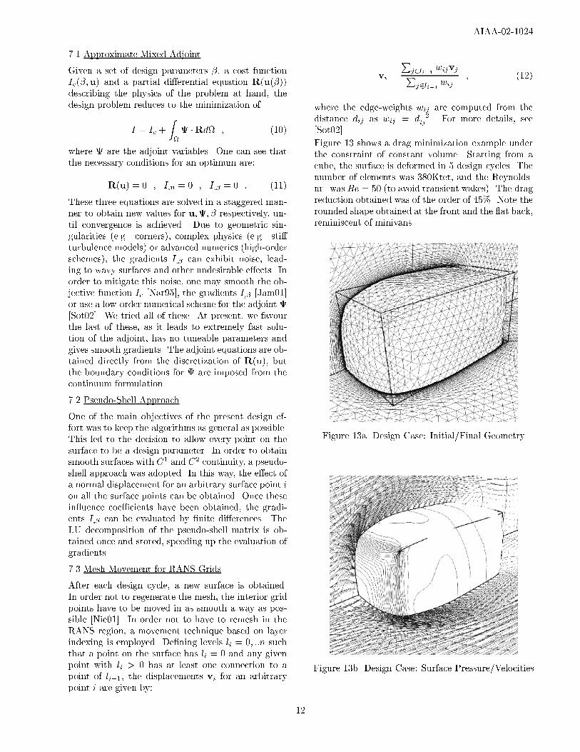
Figure 13 shows a drag minimization example underthe constraint of constant volume. Starting from acube, the surface is deformed in 5 design cycles. Thenumber of elements was 380Ktet, and the Reynolds-nr. was Re = 50 (to avoid transient wakes). The dragreduction obtained was of the order of 45%. Note therounded shape obtained at the front and the at back,reminiscent of minivans.
Figure 13a Design Case: Initial/Final Geometry
Figure 13b Design Case: Surface Pressure/Velocities
12

AIAA-02-1024
8. CONCLUSIONS AND OUTLOOK
The year 2001 has seen a number of important de-velopments and improvements for FEFLO. Notableamong these are:
- Boolean operations of discrete surfaces;- Advances in the gridding of surfaces given as dis-crete data;
- Improvements in RANS gridding;- New implicit-advection projection solver for in-compressible ows;
- Inclusion of vorticity con�nement to track vor-tices over large distances;
- Combination of Baldwin-Lomax and Smagorin-sky turbulence models;
- Arbitrary-gas equation of state lookup;- Combustion modeling;- Local remeshing for simulations with topologychange;
- Embedded grids for complex uid-structure in-teraction applications;
- Complete port to OpenMP;- Port to NEC-SX5;- New renumbering techniques to minimize indi-rect addressing.
- Advances in general design methodologies;
Planned future developments include:- Proper treatment of very large values of porosity;- Higher �delity HE and afterburn models;- Improved RANS gridding;- Implicit incompressible ow solvers;- Higher order boundary conditions for embeddedCSD triangulations;
- Parameter space scoping interface for distributedcomputing environments;
- User-friendly design and optimization modulesthat can be used as post-processors by the non-expert user; and
- Automatic construction of skeletons for tubulardomains.
9. ACKNOWLEDGEMENTS
This work was partially supported by AFOSR, DTRAand SAIC IR&D. The parallelization of FEFLO dur-ing 1995-2000 was partially supported by the DoDHPC Modernization O�ce under the CHSSI FEFLOproject. Several of the runs shown in this paper werecarried out on HPCMOmachines. The assistance andsupport for these runs is greatfully acknowledged.
10. REFERENCES
[Aft00] M.J. Aftosmis, M.J. Berger and G. Adomavi-cius - A Parallel Multilevel Method for AdaptivelyRe�ned Cartesian Grids with Embedded Boundaries;AIAA-00-0808 (2000).
[Bal78] B.S. Baldwin and H. Lomax - Thin-Layer Ap-proximation and Algebraic Model for Separated Tur-bulent Flows; AIAA-78-257 (1978).
[Bau91] J.D. Baum and R. L�ohner - Numerical Simu-lation of Shock Interaction with a Modern Main Bat-tle�eld Tank; AIAA-91-1666 (1991).
[Bau93] J.D. Baum and R. L�ohner - Numerical Sim-ulation of Pilot/Seat Ejection from an F-16; AIAA-93-0783 (1993).
[Bau93] J.D. Baum. H. Luo and R. L�ohner - Nu-merical Simulation of a Blast Inside a Boeing 747;AIAA-93-3091 (1993).
[Bau94] J.D. Baum, H. Luo and R. L�ohner - A NewALE Adaptive Unstructured Methodology for theSimulation of Moving Bodies; AIAA-94-0414 (1994).
[Bau95] J.D. Baum, H. Luo and R. L�ohner - Numer-ical Simulation of Blast in the World Trade Center;AIAA-95-0085 (1995).
[Bau95] J.D. Baum, H. Luo and R. L�ohner - Valida-tion of a New ALE, Adaptive Unstructured MovingBody Methodology for Multi-Store Ejection Simula-tions; AIAA-95-1792 (1995).
[Bau96] J.D. Baum, H. Luo, R. L�ohner, C.Yang, D. Pelessone and C. Charman - A CoupledFluid/Structure Modeling of Shock Interaction witha Truck; AIAA-96-0795 (1996).
[Bau97] J.D. Baum, H. Luo, R. L�ohner, E. Goldbergand A. Feldhun - Application of Unstructured Adap-tive Moving Body Methodology to the Simulation ofFuel Tank Separation From an F-16 C/D Fighter;AIAA-97-0166 (1997).
[Bau97] J.D. Baum, R. L�ohner, T.J. Marquette andH. Luo - Numerical Simulation of Aircraft CanopyTrajectory; AIAA-97-1885 (1997).
[Bau99] J.D. Baum, H. Luo, E. Mestreau, R. L�ohner,D. Pelessone and C. Charman - A Coupled CFD/CSDMethodology for Modeling Weapon Detonation andFragmentation; AIAA-99-0794 (1999).
[Bau01] J.D. Baum, H.Luo, E.L. Mestreau, D.Sharov, R. L�ohner, D. Pelessone and Ch. Char-man - Recent Developments of a Coupled CFD/CSDMethodology; AIAA-01-2618 (2001).
[Bau01] J.D. Baum, H.Luo, E.L. Mestreau, D.Sharov, R. L�ohner, D. Pelessone and Ch. Char-man - Recent Developments of a Coupled CFD/CSDMethodology for Simulating Structural Response toAirblast and Fragment Loading; Paper presented atICCS 2001, San Francisco, CA, May (2001).
[Ceb99] J.R. Cebral and R. L�ohner - From Medi-cal Images to CFD Meshes; Proc. 8th Int. MeshingRoundtable, South Lake Tahoe, October (1999).
13

AIAA-02-1024
[Ceb00] J.R. Cebral and R. L�ohner - AutomaticGrid Generation for Anatomically Accurate Compu-tational Hemodynamics Calculations; Proc. ICMMB-11, April 2-5, Hawaii (2000).
[Ceb00] J.R. Cebral and R. L�ohner - Image-Based Computational Hemodynamics; Proc. WorldCongress in Medical Physics and Biomedical Engi-neering, Chicago, Illinois, July 23-28 (2000).
[Ceb00] J.R. Cebral, R. L�ohner and J. Burgess - Com-puter Simulation of Cerebral Artery Clipping: Rele-vance to Aneurysm Neuro-Surgery Planning; Proc. ofECCOMAS 2000 Conf. , Barcelona, Spain, Septem-ber (2000).
[Ceb01] J.R. Cebral and R. L�ohner - Flow Visualiza-tion On Unstructured Grids Using Geometrical Cuts,Vortex Detection and Shock Surfaces; AIAA-01-0915(2001).
[Ceb01] J.R. Cebral and R. L�ohner - From Medi-cal Images to Anatomically Accurate Finite ElementGrids; Int. J. Num. Meth. Eng. 51, 985-1008 (2001).
[Ceb01] J.R. Cebral, R. L�ohner, P.L. Choyke and P.J.Yim - Merging of Intersecting Triangulations for Fi-nite Element Modeling; J. of Biomechanics 34, 815-819 (2001).
[Ceb02] J.R. Cebral, F.E. Camelli and R. L�ohner -Unstructured Grid Generation Over Buildings Inter-secting Terrain Data Using a Feature-Preserving Vol-umetric Technique; AIAA-02-0860 (2002).
[Clo82] L.D. Cloutman, J.K. Dukowicz, J.D.Ramshaw and A.A. Amsden - CONCHAS-SPRAY: AComputer Code for Reactive Flows with Fuel Sprays;LA-9294-MS (1982).
[Con00] G.S. Constantinescu and K.D. Squires - LESand DES Investigations of Turbulent Flow over aSphere; AIAA-00-0540 (2000).
[Geo98] P.L. George and H. Borouchaki - DelaunayTriangulation and Meshing; Editions Hermes, Paris(1998).
[Jam01] A.Jameson and J. Vassberg - ComputationalFluid Dynamics for Aerodynamics Design: Its Cur-rent and Future Impact; AIAA-01-0538 (2001).
[Kar95] S.L. Karman - SPLITFLOW: A 3-D Unstruc-tured Cartesian/Prismatic Grid CFD Code for Com-plex Geometries; AIAA-95-0343 (1995).
[L�oh87] R. L�ohner, K. Morgan, J. Peraire and M.Vahdati - Finite Element Flux-Corrected Transport(FEM-FCT) for the Euler and Navier-Stokes Equa-tions; ICASE Rep. 87-4, Int. J. Num. Meth. Fluids7, 1093-1109 (1987).
[L�oh90] R. L�ohner - Three-Dimensional Fluid-Structure Interaction Using a Finite Element Solver
and Adaptive Remeshing; Computer Systems in En-gineering 1, 2-4, 257-272 (1990).
[L�oh95]] R. L�ohner and R. Ramamurti - A LoadBalancing Algorithm for Unstructured Grids; Comp.Fluid Dyn. 5, 39-58 (1995).
[L�oh96] R. L�ohner - Regridding Surface Triangula-tions; J. Comp. Phys. 126, 1-10 (1996).
[L�oh96] R. L�ohner - Extensions and Improvementsof the Advancing Front Grid Generation Technique;Comm. Num. Meth. Eng. 12, 683-702 (1996).
[L�oh97] R. L�ohner - Automatic Unstructured GridGenerators; Finite Elements in Analysis and Design25, 111-134 (1997).
[L�oh98] R. L�ohner - Renumbering Strategies forUnstructured-Grid Solvers Operating on Shared-Memory, Cache-Based Parallel Machines; Comp.Meth. Appl. Mech. Eng. 163, 95-109 (1998).
[L�oh98] R. L�ohner - Computational Aspects of Space-Marching; AIAA-98-0617 (1998).
[L�oh98] R. L�ohner, C. Yang and E. O~nate - Vis-cous Free Surface Hydrodynamics Using Unstruc-tured Grids; Proc. 22nd Symp. Naval Hydrodynamics, Washington, D.C., August (1998).
[L�oh99] R. L�ohner - Generation of UnstructuredGrids Suitable for RANS Calculations; AIAA-99-0662(1999).
[L�oh99] R. L�ohner, Chi Yang, E. O~nate and S.Idelssohn - An Unstructured Grid-Based, ParallelFree Surface Solver; Appl. Num. Math. 31, 271-293(1999).
[L�oh99] R. L�ohner, Chi Yang, J.D. Baum, H. Luo,D. Pelessone and C. Charman - The Numerical Simu-lation of Strongly Unsteady Flows With Hundreds ofMoving Bodies; Int. J. Num. Meth. Fluids 31, 113-120(1999).
[L�oh99] R. L�ohner, C. Yang, J. Cebral, J.D. Baum,H. Luo, E. Mestreau, D. Pelessone and C. Charman- Fluid-Structure Interaction Algorithms for Rup-ture and Topology Change; Proc. 1999 JSME Com-putational Mechanics Division Meeting, Matsuyama,Japan, November (1999).
[L�oh00] R. L�ohner - A Parallel Advancing Front GridGeneration Scheme; AIAA-00-1005 (2000).
[L�oh00] R. L�ohner, O. Soto and F. Camelli - On Im-plicit Projection Schemes; 4th Annual GMU Trans-port and Dispersion Modeling Workshop, Fairfax,VA, July (2000).
[L�oh00] R. L�ohner - Advances in UnstructuredGrid Generation; Proc. of ECCOMAS 2000 Conf. ,Barcelona, Spain, September (2000).
14

AIAA-02-1024
[L�oh01] R. L�ohner, D. Sharov, H. Luo and R. Rama-murti - Overlapping Unstructured Grids; AIAA-01-0439 (2001).
[L�oh01] R. L�ohner, Chi Yang, J. Cebral, O. Soto, F.Camelli, J.D. Baum, H. Luo, E. Mestreau, D. Sharov,R. Ramamurti, W. Sandberg and Ch. Oh - Advancesin FEFLO; AIAA-01-0592 (2001).
[L�oh01] R. L�ohner, J. Cebral, O. Soto, P. Yim and J.Burgess - CFD in Medicine and Life Sciences - Appli-cations on the Living Human Being; paper presentedat the 5th World Conf. on Applied Fluid Dynamics,Freiburg i.Br., Germany, July (2001).
[L�oh01] R. L�ohner - Applied CFD Techniques; J. Wi-ley & Sons (2001).
[L�oh01] R. L�ohner and Chi Yang - Tracking Vor-tices Over Large Distances Using Vorticity Con�ne-ment; ECCOMAS CFD 2001 Conf. , Swansea, Wales,September (2001).
[L�oh02] R. L�ohner and M. Galle - Minimization ofIndirect Addressing for Edge-Based Field Solvers;AIAA-02-0967 (2002).
[Luo94] H. Luo, J.D. Baum and R. L�ohner - Edge-Based Finite Element Scheme for the Euler Equa-tions; AIAA J. 32, 6, 1183-1190 (1994).
[Luo94] H. Luo, J.D. Baum, R. L�ohner and J. Ca-bello - Implicit Finite Element Schemes and Bound-ary Conditions for Compressible Flows on Unstruc-tured Grids; AIAA-94-0816 (1994).
[Luo98] H. Luo, J.D. Baum and R. L�ohner - A Fast,Matrix-Free Implicit Method for Compressible Flowson Unstructured Grids; J. Comp. Phys. 146, 664-690(1998).
[Luo99] H. Luo, J.D. Baum and R. L�ohner - An Accu-rate, Fast, Matrix-Free Implicit Method for Comput-ing Unsteady Flows on Unstructured Grids; AIAA-99-0937 (1999).
[Luo00] H. Luo, D. Sharov, J.D. Baum and R. L�ohner- A Class of Matrix-free Implicit Methods for Com-pressible Flows on Unstructured Grids; First Interna-tional Conference on Computational Fluid Dynamics,Kyoto, Japan, July 10-14 (2000).
[Luo01] H. Luo, J.D. Baum and R. L�ohner - AFast, Matrix-Free Implicit Method for ComputingLow Mach Number Flows on Unstructured Grids; Int.J. CFD 14, 133-157 (2001).
[Luo01] H. Luo, D. Sharov, J.D. Baum and R. L�ohner- On the Computation of Compressible TurbulentFlows on Unstructured Grids; Int. J. CFD 14, 253-270 (2001).
[McB94] B. McBride and S. Gordon; NASA RP-1311,PART I (1994), NASA RP-1311, PART II, (1996).
[Mel93] J.E. Melton, M.J. Berger and M.J. Aftosmis- 3-D Applications of a Cartesian Grid Euler Method;AIAA-93-0853-CP (1993).
[Mou00] M. Moulton and J. Steinho� - A Techniquefor the Simulation of Stall with Coarse-Grid CFD;AIAA-00-0277 (2000).
[Mur01] M. Murayama, K. Nakahashi and S.Obayashi - Numerical Simulation of Vortical FlowsUsing Vorticity Con�nement Coupled With Unstruc-tured Grid; AIAA-01-0606 (2001).
[Nar95] R. Narducci, B.Grossman, M. Valorani, A.Dadone and R. Haftka - Optimization Methods forNon-Smooth or Noisy Objective Functions in FluidDesign Problems; AIAA-95-1648-CP (1995).
[Nie01] E.J. Nielsen and W.K. Anderson - Recent Im-provements in Aerodynamic Design Optimization onUnstructured Meshes; AIAA-01-0596 (2001).
[Ram93] R. Ramamurti and R. L�ohner - Simulationof Flow Past Complex Geometries Using a ParallelImplicit Incompressible Flow Solver; pp. 1049,1050in Proc. 11th AIAA CFD Conf. , Orlando, FL, July(1993).
[Ram96] R. Ramamurti and R. L�ohner - A ParallelImplicit Incompressible Flow Solver Using Unstruc-tured Meshes; Computers and Fluids 25, 2, 119-132(1996).
[Ram99] R. Ramamurti, W.C. Sandberg and R.L�ohner - Computation of Unsteady Flow Past De-forming Geometries; Int. J. Comp. Fluid Dyn. , 83-99(1999).
[Ram01] R. Ramamurti, W.C. Sandberg, R. L�ohner,J.A. Walker and M.W.Westneat - Unsteady 3-DComputation of Pectoral Fin Swimming in the BirdWrasse, J. Exp. Biol. (in preparation).
[Sha00] D. Sharov, H. Luo, J.D. Baum and R. L�ohner- Implementation of Untructured Grid GMRES+LU-SGS Method on Shared-Memory, Cache-Based Paral-lel Computers; AIAA-00-0927 (2000).
[Sha00] D. Sharov, H. Luo, J.D. Baum and R. L�ohner- Time-Accurate Implicit ALE Algorithm for Shared-Memory Parallel Computers; First International Con-ference on Computational Fluid Dynamics, Kyoto,Japan, July 10-14 (2000).
[Sho99] A. Shostko, R. L�ohner and W.C. Sandberg -Surface Triangulations Over Intersecting Geometries;Int. J. Num. Meth. Eng. 44, 1359-1376 (1999).
[Sma63] J. Smagorinsky - General Circulation Exper-iments with the Primitive Equations, I. The BasicExperiment; Mon. Weather Rev. , 91, 99-164 (1963).
15

AIAA-02-1024
[Sot01] O. Soto and R. L�ohner - CFD Shape Opti-mization Using an Incomplete-Gradient Adjoint For-mulation; Int. J. Num. Meth. Eng. 51, 735-753 (2001).
[Sot01] O. Soto and R. L�ohner - General Methodolo-gies for Incompressible Flow Design Problems; AIAA-01-1061 (2001).
[Sot02] O. Soto and R. L�ohner - A Mixed Adjoint For-mulation for Incompressible RANS Problems; AIAA-02-0426 (2002).
[Spa97] P.R. Spalart, W.H. Jou, M. Strelets and S.R.Allamras - Comments on the Feasibility of LES forWings, and on a Hybrid RANS/LES Approach; FirstAFOSR Int. Conf. on DNS/LES, Rouston, Louisiana,USA (1997).
[Ste92] J. Steinho�, W.Yonghu, T. Mersch and H.Senge - Computational Vorticity Capturing: Appli-cation to Helicopter Rotor Flow; AIAA-92 (Reno)(1992).
[Ste94] J. Steinho� - Vorticity Con�nement: A NewTechnique for Computing Vortex Dominated Flows;pp. 235-263 in Frontiers of Computational Fluid Dy-namics (D.A. Caughey and M.M. Hafez eds.), J. Wi-ley & Sons (1994).
[Ste99] J. Steinho�, W. Yonghu and W. Lesong -E�cient Computation of Separating High ReynoldsNumber Incompressible Flows Using Vorticity Con-�nement; AIAA-99-3316-CP (1999).
[Til02] R. Tilch and R. L�ohner - Advances in DiscreteSurface Grid Generation: Towards a Reliable Indus-trial Tool for CFD; AIAA-02-0862 (2002).
[Tus98] J. Tuszynski and R. L�ohner - Parallelizing theConstruction of Indirect Access Arrays for Shared-Memory Machines; Comm. Appl. Num. Meth. Eng.14, 773-781 (1998).
[Zee91] D. de Zeeuw and K. Powell - An Adaptively-Re�ned Cartesian Mesh Solver for the Euler Equa-tions; AIAA-91-1542 (1991).
16