RSC Advances - PAPER
10
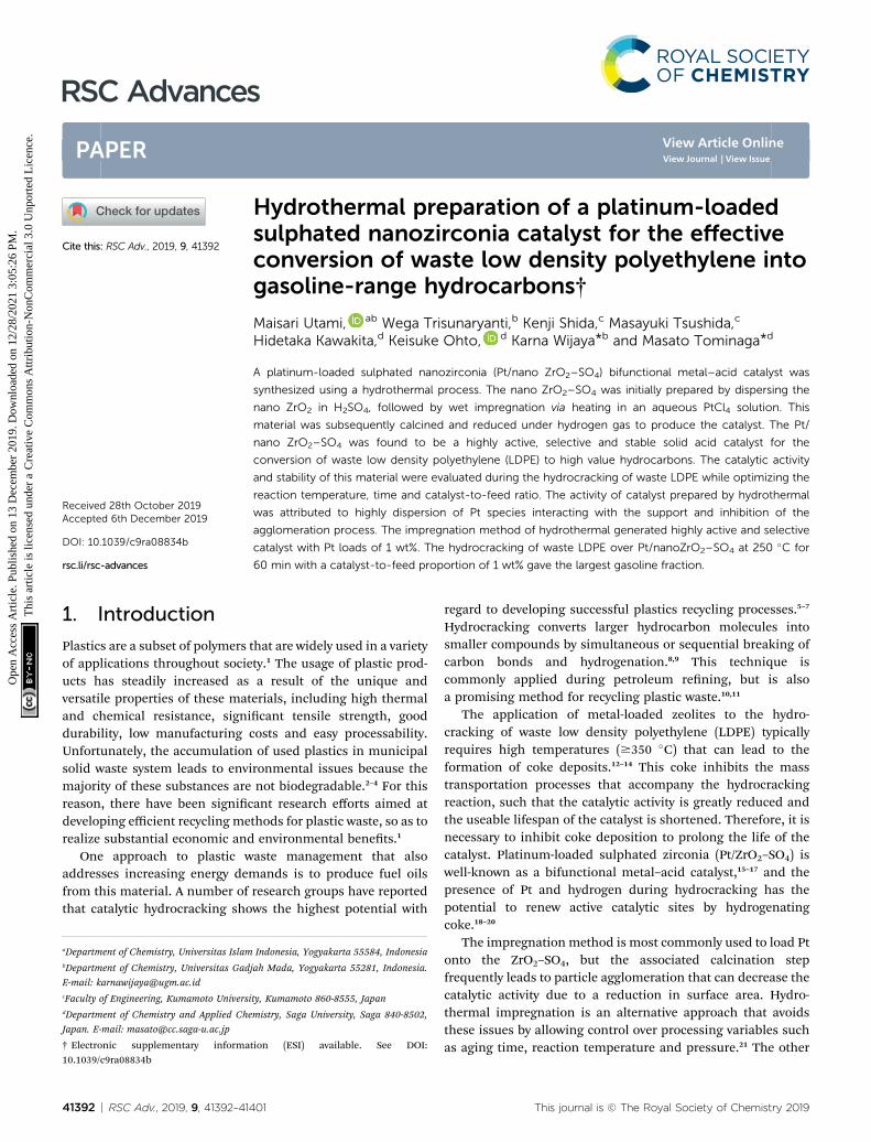
Hydrothermal preparation of a platinum-loaded sulphated nanozirconia catalyst for the effective conversion of waste low density polyethylene into gasoline-range hydrocarbons† Maisari Utami, ab Wega Trisunaryanti, b Kenji Shida, c Masayuki Tsushida, c Hidetaka Kawakita, d Keisuke Ohto, d Karna Wijaya * b and Masato Tominaga * d A platinum-loaded sulphated nanozirconia (Pt/nano ZrO 2 –SO 4 ) bifunctional metal–acid catalyst was synthesized using a hydrothermal process. The nano ZrO 2 –SO 4 was initially prepared by dispersing the nano ZrO 2 in H 2 SO 4 , followed by wet impregnation via heating in an aqueous PtCl 4 solution. This material was subsequently calcined and reduced under hydrogen gas to produce the catalyst. The Pt/ nano ZrO 2 –SO 4 was found to be a highly active, selective and stable solid acid catalyst for the conversion of waste low density polyethylene (LDPE) to high value hydrocarbons. The catalytic activity and stability of this material were evaluated during the hydrocracking of waste LDPE while optimizing the reaction temperature, time and catalyst-to-feed ratio. The activity of catalyst prepared by hydrothermal was attributed to highly dispersion of Pt species interacting with the support and inhibition of the agglomeration process. The impregnation method of hydrothermal generated highly active and selective catalyst with Pt loads of 1 wt%. The hydrocracking of waste LDPE over Pt/nanoZrO 2 –SO 4 at 250 C for 60 min with a catalyst-to-feed proportion of 1 wt% gave the largest gasoline fraction. 1. Introduction Plastics are a subset of polymers that are widely used in a variety of applications throughout society. 1 The usage of plastic prod- ucts has steadily increased as a result of the unique and versatile properties of these materials, including high thermal and chemical resistance, signicant tensile strength, good durability, low manufacturing costs and easy processability. Unfortunately, the accumulation of used plastics in municipal solid waste system leads to environmental issues because the majority of these substances are not biodegradable. 2–4 For this reason, there have been signicant research efforts aimed at developing efficient recycling methods for plastic waste, so as to realize substantial economic and environmental benets. 1 One approach to plastic waste management that also addresses increasing energy demands is to produce fuel oils from this material. A number of research groups have reported that catalytic hydrocracking shows the highest potential with regard to developing successful plastics recycling processes. 5–7 Hydrocracking converts larger hydrocarbon molecules into smaller compounds by simultaneous or sequential breaking of carbon bonds and hydrogenation. 8,9 This technique is commonly applied during petroleum rening, but is also a promising method for recycling plastic waste. 10,11 The application of metal-loaded zeolites to the hydro- cracking of waste low density polyethylene (LDPE) typically requires high temperatures ($350 C) that can lead to the formation of coke deposits. 12–14 This coke inhibits the mass transportation processes that accompany the hydrocracking reaction, such that the catalytic activity is greatly reduced and the useable lifespan of the catalyst is shortened. Therefore, it is necessary to inhibit coke deposition to prolong the life of the catalyst. Platinum-loaded sulphated zirconia (Pt/ZrO 2 –SO 4 ) is well-known as a bifunctional metal–acid catalyst, 15–17 and the presence of Pt and hydrogen during hydrocracking has the potential to renew active catalytic sites by hydrogenating coke. 18–20 The impregnation method is most commonly used to load Pt onto the ZrO 2 –SO 4 , but the associated calcination step frequently leads to particle agglomeration that can decrease the catalytic activity due to a reduction in surface area. Hydro- thermal impregnation is an alternative approach that avoids these issues by allowing control over processing variables such as aging time, reaction temperature and pressure. 21 The other a Department of Chemistry, Universitas Islam Indonesia, Yogyakarta 55584, Indonesia b Department of Chemistry, Universitas Gadjah Mada, Yogyakarta 55281, Indonesia. E-mail: [email protected] c Faculty of Engineering, Kumamoto University, Kumamoto 860-8555, Japan d Department of Chemistry and Applied Chemistry, Saga University, Saga 840-8502, Japan. E-mail: [email protected] † Electronic supplementary information (ESI) available. See DOI: 10.1039/c9ra08834b Cite this: RSC Adv. , 2019, 9, 41392 Received 28th October 2019 Accepted 6th December 2019 DOI: 10.1039/c9ra08834b rsc.li/rsc-advances 41392 | RSC Adv. , 2019, 9, 41392–41401 This journal is © The Royal Society of Chemistry 2019 RSC Advances PAPER Open Access Article. Published on 13 December 2019. Downloaded on 12/28/2021 3:05:26 PM. This article is licensed under a Creative Commons Attribution-NonCommercial 3.0 Unported Licence. View Article Online View Journal | View Issue
-
Upload
khangminh22 -
Category
Documents
-
view
0 -
download
0
Transcript of RSC Advances - PAPER
RSC Advances
PAPER
Ope
n A
cces
s A
rtic
le. P
ublis
hed
on 1
3 D
ecem
ber
2019
. Dow
nloa
ded
on 1
2/28
/202
1 3:
05:2
6 PM
. T
his
artic
le is
lice
nsed
und
er a
Cre
ativ
e C
omm
ons
Attr
ibut
ion-
Non
Com
mer
cial
3.0
Unp
orte
d L
icen
ce.
View Article OnlineView Journal | View Issue
Hydrothermal pr
aDepartment of Chemistry, Universitas IslambDepartment of Chemistry, Universitas Gad
E-mail: [email protected] of Engineering, Kumamoto UniversidDepartment of Chemistry and Applied Che
Japan. E-mail: [email protected]
† Electronic supplementary informa10.1039/c9ra08834b
Cite this: RSC Adv., 2019, 9, 41392
Received 28th October 2019Accepted 6th December 2019
DOI: 10.1039/c9ra08834b
rsc.li/rsc-advances
41392 | RSC Adv., 2019, 9, 41392–414
eparation of a platinum-loadedsulphated nanozirconia catalyst for the effectiveconversion of waste low density polyethylene intogasoline-range hydrocarbons†
Maisari Utami, ab Wega Trisunaryanti,b Kenji Shida,c Masayuki Tsushida,c
Hidetaka Kawakita,d Keisuke Ohto, d Karna Wijaya*b and Masato Tominaga*d
A platinum-loaded sulphated nanozirconia (Pt/nano ZrO2–SO4) bifunctional metal–acid catalyst was
synthesized using a hydrothermal process. The nano ZrO2–SO4 was initially prepared by dispersing the
nano ZrO2 in H2SO4, followed by wet impregnation via heating in an aqueous PtCl4 solution. This
material was subsequently calcined and reduced under hydrogen gas to produce the catalyst. The Pt/
nano ZrO2–SO4 was found to be a highly active, selective and stable solid acid catalyst for the
conversion of waste low density polyethylene (LDPE) to high value hydrocarbons. The catalytic activity
and stability of this material were evaluated during the hydrocracking of waste LDPE while optimizing the
reaction temperature, time and catalyst-to-feed ratio. The activity of catalyst prepared by hydrothermal
was attributed to highly dispersion of Pt species interacting with the support and inhibition of the
agglomeration process. The impregnation method of hydrothermal generated highly active and selective
catalyst with Pt loads of 1 wt%. The hydrocracking of waste LDPE over Pt/nanoZrO2–SO4 at 250 �C for
60 min with a catalyst-to-feed proportion of 1 wt% gave the largest gasoline fraction.
1. Introduction
Plastics are a subset of polymers that are widely used in a varietyof applications throughout society.1 The usage of plastic prod-ucts has steadily increased as a result of the unique andversatile properties of these materials, including high thermaland chemical resistance, signicant tensile strength, gooddurability, low manufacturing costs and easy processability.Unfortunately, the accumulation of used plastics in municipalsolid waste system leads to environmental issues because themajority of these substances are not biodegradable.2–4 For thisreason, there have been signicant research efforts aimed atdeveloping efficient recycling methods for plastic waste, so as torealize substantial economic and environmental benets.1
One approach to plastic waste management that alsoaddresses increasing energy demands is to produce fuel oilsfrom this material. A number of research groups have reportedthat catalytic hydrocracking shows the highest potential with
Indonesia, Yogyakarta 55584, Indonesia
jah Mada, Yogyakarta 55281, Indonesia.
ty, Kumamoto 860-8555, Japan
mistry, Saga University, Saga 840-8502,
tion (ESI) available. See DOI:
01
regard to developing successful plastics recycling processes.5–7
Hydrocracking converts larger hydrocarbon molecules intosmaller compounds by simultaneous or sequential breaking ofcarbon bonds and hydrogenation.8,9 This technique iscommonly applied during petroleum rening, but is alsoa promising method for recycling plastic waste.10,11
The application of metal-loaded zeolites to the hydro-cracking of waste low density polyethylene (LDPE) typicallyrequires high temperatures ($350 �C) that can lead to theformation of coke deposits.12–14 This coke inhibits the masstransportation processes that accompany the hydrocrackingreaction, such that the catalytic activity is greatly reduced andthe useable lifespan of the catalyst is shortened. Therefore, it isnecessary to inhibit coke deposition to prolong the life of thecatalyst. Platinum-loaded sulphated zirconia (Pt/ZrO2–SO4) iswell-known as a bifunctional metal–acid catalyst,15–17 and thepresence of Pt and hydrogen during hydrocracking has thepotential to renew active catalytic sites by hydrogenatingcoke.18–20
The impregnation method is most commonly used to load Ptonto the ZrO2–SO4, but the associated calcination stepfrequently leads to particle agglomeration that can decrease thecatalytic activity due to a reduction in surface area. Hydro-thermal impregnation is an alternative approach that avoidsthese issues by allowing control over processing variables suchas aging time, reaction temperature and pressure.21 The other
This journal is © The Royal Society of Chemistry 2019

Paper RSC Advances
Ope
n A
cces
s A
rtic
le. P
ublis
hed
on 1
3 D
ecem
ber
2019
. Dow
nloa
ded
on 1
2/28
/202
1 3:
05:2
6 PM
. T
his
artic
le is
lice
nsed
und
er a
Cre
ativ
e C
omm
ons
Attr
ibut
ion-
Non
Com
mer
cial
3.0
Unp
orte
d L
icen
ce.
View Article Online
advantage of using hydrothermal methods is that materials canbe produced in high purity with tuneable particle sizes andstable pore structures, using low temperatures and a simplepreparation process.22 Furthermore, the hydrothermal reactionmedia have low viscosities and thus minimal resistance to masstransfer. Consequently, hydrothermal technique is an effectivemeans of loading active species onto a support to give a highlydispersed catalyst.23–25 Despite this, to the best of our bestknowledge, the use of hydrothermal methods to load Pt ontothe nano ZrO2–SO4 has not yet been reported. The present studydeveloped a novel platinum-loaded sulphated nanozirconia (Pt/nano ZrO2–SO4) catalyst using an advanced hydrothermalprocess. This material was found to be highly active at relativelylow temperatures during the conversion of waste LDPE intogasoline-range hydrocarbons.
2. Experimental2.1 Materials
Zirconium dioxide nanopowder (nano ZrO2, 60–70 nm,$99.90%) was provided by the Hongwu International Group,Ltd. (Guangzhou, China) and tetrachloroplatinum (PtCl4,$99.90%) was supplied by the Zibo Jiashitai Chemical Tech-nology Co., Ltd. (Zibo, China). A sulphuric acid solution (H2SO4,98%) and ammonium hydroxide solution (NH4OH, 25%) wereobtained from Merck (Germany). All chemicals were analyticalgrade and used as received. The LDPE comprised commonlyused plastics collected from household waste. Hydrogen gas(H2, 99.99%) was supplied by PT Samator Gas Industri (Yogya-karta, Indonesia).
2.2 Methods
The nano ZrO2 was dispersed in a 0.8 mol dm�3 H2SO4 solution.The powder was then ltrated, dried in an oven at 100 �C for24 h and calcined at 600 �C for 4 h.26 A quantity of this calcinednano ZrO2–SO4 was dispersed in an aqueous solution of PtCl4(1 wt% Pt) in a Teon-lined stainless steel autoclave and heatedat 90 �C for 4 h. The resulting paste was then dried in an oven at100 �C for 24 h and calcined at 600 �C for 4 h, followed by thereduction of Pt4+ to Pt0 under a hydrogen gas stream (20mLmin�1) at 400 �C for 3 h. The obtained material is referred toherein as Pt/nano ZrO2–SO4.
Scanning electron microscopy (SEM) imaging and elementalmapping were performed using a JEOL JSM-6510 (Japan) inconjunction with an energy-dispersive X-ray spectrometry (EDX)detector, employing a JED-2300 Analysis Station (Japan). Spec-imens were placed on a carbon coated sample holder prior tothese SEM-EDX mapping observations. Characterization byFourier transform infrared spectroscopy (FTIR) was performedusing a Shimadzu Prestige-21 (Japan), scanning the range of4000–400 cm�1 and employing the KBr disc technique. X-rayphotoelectron spectroscopy (XPS) data were acquired witha Shimadzu AXIS-ULTRADLD (Japan). The binding energyvalues were calibrated using the C 1s peak at 284.7 eV. X-raydiffraction (XRD) characterization was carried out using a Shi-madzu XRD-7000 (Japan) with CuKa radiation (Ni ltered) at l
This journal is © The Royal Society of Chemistry 2019
¼ 1.5418 A over the range of 2q ¼ 4–80�. Gas sorption analysis(GSA) was performed using a Quantachrome NOVA 1200e (USA)over the P/Po range of 0.005–0.999 at 77.3 K, using liquidnitrogen.
Thermogravimetric analysis (TGA) data were obtained witha Shimadzu DTG-60H (Japan) at a heating rate of 10 �C min�1
from room temperature to 900 �C under an atmospherecomposed of nitrogen (80%) and oxygen (20%). The acidity ofthe catalysts was determined based on the adsorption ofammonia using a gravimetric method.
A feedstock for the hydrocracking reaction was prepared byvaporizing waste LDPE in a pyrolysis reactor at 300 �C for 3 hand condensing the vapor into liquid. Hydrocracking of theheavy oil obtained from pyrolysis was performed using eithernano ZrO2, nano ZrO2–SO4 or Pt/nano ZrO2–SO4 catalysts undera hydrogen gas stream (20 mL min�1) in a ow reactor.7 Thecatalytic activities of these materials were assessed at varioustemperatures, reaction times and catalyst-to-feed ratios. Prod-ucts were characterized by gas chromatography-mass spec-trometry (GC-MS) using a Shimadzu QP 2010S (Japan) with anRtXi-5MS column (length 30 m, diameter 0.25 mm and lmthickness 0.25 mm) and an electron ionization detector. Furtherdetails of this analysis are provided in ESI.†
3. Results and discussion3.1 Electron microscopy characterization
The SEM images obtained for the nano ZrO2, nano ZrO2–SO4
and Pt/nano ZrO2–SO4 are shown in Fig. 1. It can be seen thatthe surface morphology of the nano ZrO2 precursor was notsignicantly changed aer the addition of sulphate and Pt.However, the nano ZrO2–SO4 does exhibit increased agglomer-ation. The nano ZrO2 surface topography aer acid modica-tion shows a typical porous material that has a rough structurewith irregular shapes. It has been reported that the calcinationstep in the process used to make the sulphate facilitates thecoalescence of primary particles, leading to a signicantincrease in the particle size of the nano ZrO2.27 For nano ZrO2–
SO4 sample, some particles with different size and disorderedshape were obtained from the incorporation of very smallcrystallites during the calcination process.
The Pt/nano ZrO2–SO4 shows a typical ner surfacemorphology with smaller and more regular particle size. TheEDX spectrum of the Pt/nano ZrO2–SO4 clearly shows Pt parti-cles on the surface (Fig. 1d). This observation indicates thehomogeneous dispersion of Pt over the nano ZrO2–SO4 supportand the size of Pt particles t into the range of 2–5 nm. The sizeof the metallic Pt and support plays a crucial role in the reactionpathway to obtain the optimum catalytic activity and selectivity.The impregnation of Pt via a hydrothermal method signicantlyinhibited the particle agglomeration, thus stabilized the catalystsurface.
3.2 XPS analysis
XPS was used to obtain additional insights into the Pt compo-sition, based on comparisons of the binding energy values, so as
RSC Adv., 2019, 9, 41392–41401 | 41393

Fig. 1 SEM images of (a) nano ZrO2, (b) nano ZrO2–SO4, (c) Pt/nano ZrO2–SO4 and (d) EDX Pt mapping of Pt/nano ZrO2–SO4.
RSC Advances Paper
Ope
n A
cces
s A
rtic
le. P
ublis
hed
on 1
3 D
ecem
ber
2019
. Dow
nloa
ded
on 1
2/28
/202
1 3:
05:2
6 PM
. T
his
artic
le is
lice
nsed
und
er a
Cre
ativ
e C
omm
ons
Attr
ibut
ion-
Non
Com
mer
cial
3.0
Unp
orte
d L
icen
ce.
View Article Online
to examine the metal loading mechanism. Fig. 2 presents thedeconvoluted Pt 4f spectrum acquired from the Pt/nano ZrO2–
SO4, which contains Pt0 4f7/2 and Pt0 4f5/2 peaks, centered at 71.5and 74.8 eV, respectively. Peak is also present at 73.1 eV (Pt2+ 4f7/2) due to the presence of Pt2+ species. This result indicates thatthe Pt particles had diameters on the scale of several nm, suchthat electron interactions occurred between these particles andthe nano ZrO2–SO4 surface.28–30 In addition, Table 1 shows therelative area of the deconvoluted Pt0 4f7/2, Pt
0 4f5/2 and Pt2+ 4f7/2spectra. This result indicates that the reduction of Pt4+ under
Fig. 2 The XPS spectrum of Pt/nano ZrO2–SO4 in the Pt 4f region. Thebroken lines indicate the peaks obtained by deconvolution.
41394 | RSC Adv., 2019, 9, 41392–41401
a hydrogen gas stream was successfully formed Pt0 particleswith the total composition of 81.8%.
3.3 Surface sulphate analysis
The surface functional groups of the samples were assessed toinvestigate changes following the acid treatment and Ptloading. Fig. 3 shows the FTIR spectra of the nano ZrO2, nanoZrO2–SO4 and Pt/nano ZrO2–SO4. The spectra of the latter twomaterials contain the same peaks as the nano ZrO2 spectrum inthe range of 417–748 cm�1, which are ascribed to Zr–O–Zrbonds.27 An intense, broad band around 3449 cm�1 and anotherpeak at 1636 cm�1 are assigned to the stretching and bendingmodes of adsorbed water, respectively.31,32
The presence of SO42� ions on the nano ZrO2 surface was
conrmed by the peaks in the range of 1003–1474 cm�1,assigned to chelating bidentate bridging SO4
2� groups
Table 1 Positions and relative area percentages of deconvoluted Pt 4fpeaks
Pt 4f peak Peak position (eV) Relative area%
Pt0 4f7/2 71.5 36.4Pt0 4f5/2 74.8 45.4Pt2+ 4f7/2 73.1 18.2
This journal is © The Royal Society of Chemistry 2019

Fig. 3 FTIR spectra of (a) nano ZrO2, (b) nano ZrO2–SO4 and (c) Pt/nano ZrO2–SO4.
Fig. 4 FTIR spectra of (a) nano ZrO2, (b) nano ZrO2–SO4 and (c) Pt/nano ZrO2–SO4 after ammonia adsorption.
Paper RSC Advances
Ope
n A
cces
s A
rtic
le. P
ublis
hed
on 1
3 D
ecem
ber
2019
. Dow
nloa
ded
on 1
2/28
/202
1 3:
05:2
6 PM
. T
his
artic
le is
lice
nsed
und
er a
Cre
ativ
e C
omm
ons
Attr
ibut
ion-
Non
Com
mer
cial
3.0
Unp
orte
d L
icen
ce.
View Article Online
coordinated to Zr4+.29 The four bands at 1003, 1057, 1157 and1227 cm�1 result from symmetric S–O, asymmetric S–O,symmetric S]O and asymmetric S]O vibrations, respectively.33
The weak bands at 1404–1474 cm�1 are ascribed to thestretching vibrations of S]O bonds in adsorbed SO3 mole-cules.34 There are no appreciable shis in the band positions inthe Pt/nano ZrO2–SO4 spectrum compared with those in thenano ZrO2–SO4 spectrum, although the Pt/nano ZrO2–SO4
generated a broad SO42� band with a shoulder at 1065–
1126 cm�1 and less intense bands at 1389 and 1474 cm�1. Thesetypical SO4
2� peaks clearly indicate that the nano ZrO2 surfacewas modied with sulphate.
3.4 Catalyst acidity analysis
The catalyst acidities were estimated based on the gravimetricmethod, using the amounts of ammonia vapor absorbed by thecatalysts which were rst placed under vacuum conditions.35,36
A vacuum was applied to prevent any interference by watervapor that might have been adsorbed by the catalyst. Theacidities of the nano ZrO2, nano ZrO2–SO4 and Pt/nano ZrO2–
SO4 are summarized in Table 2, and these data demonstratethat the nano ZrO2 had low total acidity, resulting from Zr4+
species acting as Lewis acid sites. Activation of this materialthrough the sulphate treatment increased the total acidity,indicating that the relative amounts of Brønsted and Lewis acid
Table 2 The acidity values of nano ZrO2, nano ZrO2–SO4 and Pt/nanoZrO2–SO4
Sample Acidity (mmol g�1)
Nano ZrO2 0.5Nano ZrO2–SO4 2.2Pt/nano ZrO2–SO4 8.9
This journal is © The Royal Society of Chemistry 2019
sites were determined largely by the surface sulphate concen-tration.15 The acidity of the Pt/nano ZrO2–SO4 was increasedsignicantly due to the presence of Pt species acting as strongLewis acid sites.11
The strengths of Brønsted and Lewis acid sites on a catalystplay important roles in determining the catalytic activity.18–20 Inthe present work, interactions between catalyst acid sites andammonia were conrmed by FTIR spectroscopy. Fig. 4 presentsthe FTIR spectra of the nano ZrO2, nano ZrO2–SO4 and Pt/nanoZrO2–SO4 aer ammonia adsorption. Following this adsorption,the S]O and S–O bands were broadened and shied to 1119and 1396 cm�1, respectively. The symmetric bending bandaround 1119 cm�1 conrms the presence of ammonia coordi-nated to Lewis acid sites. In addition, the symmetric bendingband at 1396 cm�1 indicates ammonia in the form of a conju-gate acid based on interactions with hydrogen from Brønstedsites.35,36
3.5 XRD characterization
Fig. 5 provides the XRD patterns of the nano ZrO2, nano ZrO2–
SO4 and Pt/nano ZrO2–SO4. The ZrO2 typically used as a catalysthas only three crystal phases (tetragonal, monoclinic andmetastable tetragonal),37 and the characteristic peaks at 2q ¼28.3� (�111) and 31.6� (111) correspond to the monocliniccrystal phase.13 In general, this series of diffraction patternsindicates stable crystallinity, although the addition of sulphatemodied the crystal phase of the nano ZrO2. This is suggestedby the appearance of a new, low intensity peak at 2q ¼ 30.2�
(011), indicating the transition of the crystal phase frommonoclinic to metastable tetragonal.26
Previous research has demonstrated that the sulphateaddition process induces a phase transformation from mono-clinic to metastable tetragonal. However, this process in thepresent study did not generate a complete transformation toa tetragonal crystal phase because the phase of the nano ZrO2–
SO4 was also affected by the crystalline properties of the nano
RSC Adv., 2019, 9, 41392–41401 | 41395

Fig. 5 XRD patterns of (a) nano ZrO2, (b) nano ZrO2–SO4 and (c) Pt/nano ZrO2–SO4.
Fig. 6 Nitrogen adsorption–desorption isotherms of (a) nano ZrO2, (b)nano ZrO2–SO4 and (c) Pt/nano ZrO2–SO4.
Table 3 Textural properties of the three catalysts
Sample
BET surfacearea(m2 g�1)
Total porevolume(cm3 g�1)
Average porediameter(nm)
Nano ZrO2 25.1 0.1 3.4Nano ZrO2–SO4 16.7 0.1 4.3Pt/nano ZrO2–SO4 23.7 0.1 3.5
RSC Advances Paper
Ope
n A
cces
s A
rtic
le. P
ublis
hed
on 1
3 D
ecem
ber
2019
. Dow
nloa
ded
on 1
2/28
/202
1 3:
05:2
6 PM
. T
his
artic
le is
lice
nsed
und
er a
Cre
ativ
e C
omm
ons
Attr
ibut
ion-
Non
Com
mer
cial
3.0
Unp
orte
d L
icen
ce.
View Article Online
ZrO2 precursor. The nano ZrO2 comprised a pure monoclinicphase with a high degree of crystallinity and thermodynamicstability, such that the nano ZrO2–SO4 was also largelymonoclinic.38,39
The nano ZrO2–SO4 containing Pt produced peaks at 2q ¼39.8� and 46.2� associated with (111) and (200) reections, ashas also been reported in prior publications.20,40 In thisresearch, Pt peaks were not detected because the total amountof Pt on the surface was relatively low. Moreover, the crystalphase of the nano ZrO2 was stabilized by the addition ofsulphate.32,41,42 Therefore, there were no signicant changes inthe crystal phase aer Pt was loaded onto the nano ZrO2–SO4, asa result of the increased phase stability of this material.However, the intensities of the monoclinic and metastabletetragonal peaks were gradually decreased. The Pt/nano ZrO2–
SO4 with the highest acidity (Table 2) generated the least intensediffraction peaks out of all the catalysts. This result conrmsthat the amount of Pt was loaded on the nano ZrO2–SO4 surfacein the case of this specimen.
Fig. 7 TG curves for (a) nano ZrO2, (b) nano ZrO2–SO4 and (c) Pt/nanoZrO2–SO4.
3.6 Textural properties evaluation
Fig. 6 presents the isotherms for the samples, all of whichconform to type IV according to the IUPAC classication system.There was no appreciable change in the shape of the nano ZrO2
isotherm before and aer modication. In addition, the data inTable 3 indicate the formation of a mesoporous material basedon an average pore diameter in the range of 2–50 nm.43,44
The textural properties of each catalyst, including thespecic surface area, total pore volume and average porediameter, are summarized in Table 3. A large decrease in thespecic surface area (from 25.1 to 16.7 m2 g�1) was observedaer the addition of sulphate to nano ZrO2.7 This change wasattributed to the interaction between the nano ZrO2 andsulphate groups, which promoted agglomeration during thecalcination process. This same behaviour was also reported in
41396 | RSC Adv., 2019, 9, 41392–41401
a previous paper.45 In the present study, the decreased crystal-linity following the addition of sulphate was conrmed by XRDdata (Fig. 5). Aer Pt loading via a hydrothermal method, thespecic surface area of the catalyst was increased to 23.7 m2 g�1,which is attributed to highly dispersion of Pt species interactingwith the nano ZrO2–SO4 support and inhibition of theagglomeration process. This observation corresponds to
This journal is © The Royal Society of Chemistry 2019

Paper RSC Advances
Ope
n A
cces
s A
rtic
le. P
ublis
hed
on 1
3 D
ecem
ber
2019
. Dow
nloa
ded
on 1
2/28
/202
1 3:
05:2
6 PM
. T
his
artic
le is
lice
nsed
und
er a
Cre
ativ
e C
omm
ons
Attr
ibut
ion-
Non
Com
mer
cial
3.0
Unp
orte
d L
icen
ce.
View Article Online
elemental mapping images (Fig. 1d) for Pt/nano ZrO2–SO4.
Thus, the hydrothermal method is evidently a useful means ofcontrolling particle agglomeration of catalyst.
3.7 Thermal analysis
Fig. 7 presents TG curves obtained from the nano ZrO2, nanoZrO2–SO4 and Pt/nano ZrO2–SO4. The TG data for the nanoZrO2–SO4 before and aer Pt loading exhibit the same two massreductions steps, while the nano ZrO2 did not show anysignicant changes in mass loss. The initial decreases in massof the nano ZrO2–SO4 and Pt/nano ZrO2–SO4 occurred over therange of 50–200 �C (2.5 and 0.9%, respectively) and can beascribed to the removal of adsorbed water. The rapid masslosses in the range of 500–700 �C (5.7 and 1.5%, respectively)might indicate the loss of sulphate species.14,46 The decompo-sition of sulphate could result in structural changes thatsignicantly reduce the catalytic activity.
Table 5 A summary of catalytic cracking experiments using plasticwastea
CatalystModicationof catalyst Plastic
Hydrocrackingtemperature(�C)
3.8 Optimization of the hydrocracking reaction
The heavy oil obtained from the pyrolysis of waste LDPE wasused as the feedstock during atmospheric pressure catalytichydrocracking experiments (see Table S1 in ESI† for detailsregarding the chemical compositions). The reaction conditionswere varied to optimize the properties of the hydrocarbonproducts. In each trial, 100% conversion of the feed was ob-tained, with three main products (liquids, gases and solids) andno other residue. The liquid yield was clear yellowish oil, whilethe solid yield was black coke formed on the catalyst surface.The quality of the nal product is known to vary greatlydepending on the operating conditions.47 Therefore, the effectsof temperature, reaction time and catalyst-to-feed proportionwere evaluated to optimize the reaction process. The productdistributions obtained from the hydrocracking of waste LDPEover the nano ZrO2, nano ZrO2–SO4 and Pt/nano ZrO2–SO4 arepresented herein in terms of the selectivity for gasoline (C5–C12)and diesel (C13–C22) hydrocarbons.
The effect of temperature on the catalytic activity issummarized in Table 4. It can be seen that the greatest liquidyields were obtained at 250 �C in each case. The gasoline-range
Table 4 Product distributions from the hydrocracking of waste LDPE(t ¼ 60 min, catalyst-to-feed proportion ¼ 1 wt%)
T (�C) Sample
Yield (wt%)
Liquid
Solid GasC5–C12 C13–C20
250 Nano ZrO2 35.2 17.9 0.1 46.8Nano ZrO2–SO4 44.5 15.5 0.3 39.7Pt/nano ZrO2–SO4 56.0 13.7 0.2 30.1
300 Nano ZrO2 4.8 2.3 0.3 92.6Nano ZrO2–SO4 18.1 5.7 1.0 75.2Pt/nano ZrO2–SO4 37.1 17.7 0.3 44.9
350 Nano ZrO2 1.0 0.3 0.6 98.1Nano ZrO2–SO4 6.1 1.9 0.9 91.1Pt/nano ZrO2–SO4 12.0 3.9 0.4 83.7
This journal is © The Royal Society of Chemistry 2019
hydrocarbons generated over the nano ZrO2 and nano ZrO2–SO4
at 250 �C with selectivities of 35.2 and 44.5 wt%, respectively.When using the Pt/nano ZrO2–SO4 catalyst, the selectivity forthe gasoline fraction was 56.0 wt%. This represents a signicantincrease in the gasoline fraction, as a result of the strong acidproperties of this catalyst. These results are also in agreementwith the estimated acidity values of the three materials(Table 2).
At higher temperatures, the relative amount of coke formedon the catalyst surface increased, leading to a decrease in theliquid yields. Furthermore, the catalysts exhibited a tendencytoward deactivation and decreased catalytic activity. In the caseof the Pt/nano ZrO2–SO4, the application of high temperaturescould lead to sintering, which would be expected to degrade thecatalytic activity.48
The reactions at 350 �C over the catalysts resulted in sharpdecreases in the liquid yields and gave the highest gaseousproduct yields of 98.1, 91.1 and 83.7 wt%. These results suggestexcessive cracking5 because elevated temperatures duringhydrocracking have been shown to lower the selectivity forliquid products.49 This effect is associated with the homolysis oforganic compounds to form free radicals, which can bindhydrogen radicals to form short chain hydrocarbons that aregases under ambient conditions.50
Several experimental studies had been carried out with theaim of improving gasoline yields from plastics pyrolysis byintroducing suitable catalysts, as listed in Table 5. Variouscatalysts currently used in petroleum rening have already beentested extensively with common plastics such as waste LDPE,HDPE and PP. The experiments in these previous studies wereprimarily performed at high reaction temperatures ($350 �C).However, in this work, the addition of Pt to nano ZrO2–SO4
HZSM-5 5,51 Ion exchange LDPE 425Al-MCM-41 5,51 Sol–gel LDPE 450Silica–alumina47 — LDPE 375HZSM-5 47 Ion exchange LDPE 375Y-zeolite52 Used as received LDPE 400HZSM-5 52 Used as received LDPE 400Cr/zeolite53 Ion exchange LDPE 450Y-zeolite10 Used as received LDPE, HDPE 450Natural zeolite10 Used as received LDPE, HDPE 450Ni/zeolite11 Reux LDPE 350Ni–Mo/zeolite11 Reux LDPE 350Co/zeolite11 Reux LDPE 350Co–Mo/zeolite11 Reux LDPE 350Y-zeolite54 Used as received PP 390Pt/ZrO2–SO4
7 Reux LDPE 250This work Hydrothermal LDPE 250
a LDPE: low density polyethylene, HDPE: high density polyethylene, PP:polypropylene.
RSC Adv., 2019, 9, 41392–41401 | 41397

Table 6 Product distributions from the hydrocracking of waste LDPEover various time spans (T ¼ 250 �C, catalyst-to-feed proportion ¼1 wt%)
t (min) Sample
Yield (wt%)
Liquid
Solid GasC5–C12 C13–C20
30 Nano ZrO2 32.3 1.6 0.1 66.0Nano ZrO2–SO4 29.7 12.0 0.3 58.0Pt/nano ZrO2–SO4 33.7 8.9 0.1 57.3
60 Nano ZrO2 35.2 17.9 0.1 46.8Nano ZrO2–SO4 44.5 15.5 0.3 39.7Pt/nano ZrO2–SO4 56.0 13.7 0.2 30.1
90 Nano ZrO2 37.7 5.0 0.1 57.2Nano ZrO2–SO4 41.9 14.9 0.4 42.8Pt/nano ZrO2–SO4 44.8 25.4 0.2 29.6
Table 7 Product distributions from the hydrocracking of waste LDPEat various catalyst-to-feed proportions (T ¼ 250 �C, t ¼ 60 min)
Catalyst-to-feed(wt%) Sample
Yield (wt%)
Liquid
Solid GasC5–C12 C13–C20
1 Nano ZrO2 35.2 17.9 0.1 46.8Nano ZrO2–SO4 44.5 15.5 0.3 39.7Pt/nano ZrO2–SO4 56.0 13.7 0.2 30.1
2 Nano ZrO2 30.3 18.5 0.1 51.1Nano ZrO2–SO4 39.4 17.3 0.4 42.9Pt/nano ZrO2–SO4 46.1 14.6 0.2 39.1
3 Nano ZrO2 27.3 22.6 0.1 50.0Nano ZrO2–SO4 33.1 18.0 0.4 48.5Pt/nano ZrO2–SO4 36.0 12.9 0.3 50.8
RSC Advances Paper
Ope
n A
cces
s A
rtic
le. P
ublis
hed
on 1
3 D
ecem
ber
2019
. Dow
nloa
ded
on 1
2/28
/202
1 3:
05:2
6 PM
. T
his
artic
le is
lice
nsed
und
er a
Cre
ativ
e C
omm
ons
Attr
ibut
ion-
Non
Com
mer
cial
3.0
Unp
orte
d L
icen
ce.
View Article Online
facilitated the low-temperature hydrocracking reaction byincreasing the surface concentration of olens. These activeolen intermediates reacted with acid sites to form carbeniumion intermediates.
It has been reported that using HZSM-5 and Al-MCM-41 ascatalysts for hydrocracking at 450 �C gives the highest gasolinefraction yield from waste LDPE.5 Moreover, a Ni/Co-modiedzeolite applied to hydrocracking at 350 �C has been found toexhibit high selectivity for gasoline.11 Compared with priorstudies (Table 5), the present research demonstrated the use oflower temperature reaction, and conrmed that the hydro-cracking over the Pt/nano ZrO2–SO4 at 250 �C effectively con-verted waste LDPE into the highest gasoline fraction. This lowtemperature process would reduce energy consumption andlower operational costs.7
The Pt/ZO2–SO4 catalyst reported in prior publication hasbeen prepared via a reux method.7 The use of reux methodled to uneven dispersion of Pt that can decrease the catalyticactivity and stability. Meanwhile, in this present research, thehydrothermal method offers solution in an easier way for metalimpregnation. It succesfully produced catalyst with highlydispersion of Pt species (Fig. 1d) by controlling aging time,reaction temperature and pressure.
The effect of reaction time on the product yields wasassessed, as presented in Table 6. The conversion to liquids overthe Pt/nano ZrO2–SO4 following reaction times of 30, 60 and90 min showed a continuous increase, with values of 42.6, 69.7and 70.2 wt%, respectively. However, reaction times of 60 and90 min led to a signicant decrease in the selectivity for thegasoline fraction, going from 56.0 to 44.8 wt%. This resultindicates that a relatively long reaction time tends to increasethe formation of coke on the catalyst surface. In addition, pro-longed reaction times can promote condensation and repoly-merization reactions. Repolymerization can result in theformation of a heavy fraction and signicantly decrease thecatalytic activity. Moreover, prolonged hydrocracking reactionscan produce catalyst deactivation as reactants and productscover the active sites of the catalyst.53 Therefore, 60 min wasdetermined to be the optimum reaction time with regard to
41398 | RSC Adv., 2019, 9, 41392–41401
obtaining the highest proportion of the gasoline fraction. Theuse of a relatively short time also gives a more efficient process.
Table 7 shows the product distributions obtained from thehydrocracking of waste LDPE at various catalyst-to-feedproportions. A value of 1 wt% gave the highest catalyst activityand selectivity for the gasoline fraction. For the Pt/nano ZrO2–
SO4, increasing the catalyst proportion from 1 to 2 to 3 wt%gradually decreased the gasoline fraction (56.0, 46.1 and36.0 wt%). These results may have been due to excessivehydrocarbon reactions at higher catalyst amounts. Based on thesolid fraction compositions, it is evident that the use of a largeamount of catalyst signicantly increased coke deposits on thecatalyst surface, thus reducing the gasoline fraction. Thehydrocracking of waste LDPE over the Pt/nano ZrO2–SO4 ata catalyst-to-feed proportion of 1 wt% gave the highest selec-tivity for the gasoline fraction together with minimal cokeformation, and so is optimal (see Fig. S1 and Table S1 in ESI† fordetails regarding the chemical compositions).
3.9 Catalytic stability evaluation
The stabilities of the nano ZrO2, nano ZrO2–SO4 and Pt/nanoZrO2–SO4 were assessed at 250 �C with a reaction time of60 min and a catalyst-to-feed proportion of 1 wt%. The results,based on the liquid yields obtained upon repeated reuses, arepresented in Fig. 8. The catalytic stability of the nano ZrO2
during the hydrocracking reaction showed a gradual reductionwith repeated use, followed by a sharp decrease during thefourth cycle, while the performance of the nano ZrO2–SO4
exhibited a signicant drop in the second cycle. The rapiddeactivation of ZrO2–SO4 represents a serious drawback. Severalreasons for this phenomenon have been proposed. Theseinclude; a reduction in the oxidation state of sulphur in thesurface sulphate groups (from S6+ to lower oxidation states)leading to a decrease in the acid strength, the formation ofmacromolecules on the catalyst surface (i.e., coke formation),and the loss of sulphur as H2S.55
Fig. 9 depicts a proposed illustration for the catalytic stabilityof the nano ZrO2–SO4 with and without Pt. The overall catalyticand selectivity data suggest that the conversion of waste LDPE
This journal is © The Royal Society of Chemistry 2019

Fig. 8 Results from stability tests during the hydrocracking of wasteLDPE over (a) nano ZrO2, (b) nano ZrO2–SO4 and (c) Pt/nano ZrO2–SO4.
Fig. 9 A proposed illustration for the catalytic stability differencebetween (a) nano ZrO2–SO4 and (b) Pt/nano ZrO2–SO4.
Fig. 10 The mechanistic role of Pt and hydrogen distribution on nanoZrO2–SO4.
Paper RSC Advances
Ope
n A
cces
s A
rtic
le. P
ublis
hed
on 1
3 D
ecem
ber
2019
. Dow
nloa
ded
on 1
2/28
/202
1 3:
05:2
6 PM
. T
his
artic
le is
lice
nsed
und
er a
Cre
ativ
e C
omm
ons
Attr
ibut
ion-
Non
Com
mer
cial
3.0
Unp
orte
d L
icen
ce.
View Article Online
over the nano ZrO2–SO4 produces the highest solid yield. Theresults also demonstrate that this material had high initialactivity that rapidly decreased during subsequent cycles. Thecatalytic activity of the nano ZrO2–SO4 undergoes a signicantdecrease when in contact with hydrocarbons or water vapor athigh temperatures due to deactivation by the formation of cokedeposits over the strong acid sites.14
The calcination of deactivated catalyst in oxygen at 450 �Chas been shown to recover the original activity.55 This resultsuggests that the use of air as a carrier gas could prevent thedeactivation of the catalyst, likely by degrading hydrocarbons inthe catalyst pores.37 In the present work, the Pt-loaded catalystshowed high stability when used in the hydrocracking reactionand maintained its activity up to the sixth cycle (Fig. 8). It hasbeen reported that the deactivation of the nano ZrO2–SO4 can be
This journal is © The Royal Society of Chemistry 2019
mitigated by applying Pt to suppress coke formation. Thisoccurs due to hydrogenation via the homolytic dissociation ofhydrogen. As a result, the loading of a small amount of Pt hasbeen shown to signicantly improve the stability of the nanoZrO2–SO4 while inhibiting coke formation.18–20
The mechanistic role of Pt in the presence of hydrogen isillustrated in Fig. 10. The hydrogen molecule dissociateshomolitically on the surface of Pt particle to form two radicalhydrogen atoms which then bind to unpaired electrons in the5d orbitals of Pt. The H+ ion is released from Pt, distributed tonano ZrO2–SO4 and migrated to electron-rich oxygen sites,forming a new Brønsted acid site and suppress coke formation.Thus, Pt plays an important role as active sites for acid catalyzedreactions.
4. Conclusions
The catalyst characterizations indicate that Pt loading viaa hydrothermalmethod inhibited particle agglomeration and thusincreased the surface area of the Pt/nano ZrO2–SO4. The acidtreatment and Pt loading increased the activity and selectivity forhydrocracking of waste LDPE due to a signicant increase incatalyst acidity. The data show that Pt was successfully impreg-nated with the total composition of Pt0 was 81.8% and homoge-neously dispersed on the nano ZrO2–SO4 surface, producinga highly active and selective solid acid catalyst in the hydro-cracking reaction under low temperature reaction conditions.Liquid, solid and gas yields of 69.7, 0.2 and 30.1 wt% were ob-tained from waste LDPE hydrocracking under the optimizedconditions (a temperature of 250 �C, a reaction time of 60min anda catalyst-to-feed proportion of 1 wt%). The liquid fraction con-tained as much as 56.0 wt% gasoline-type products and 13.7 wt%diesel-type products. In addition, the Pt/nano ZrO2–SO4 showedhigh stability and maintained its activity up to the sixth cycle forthe conversion of waste LDPE into gasoline-range hydrocarbons.
Conflicts of interest
There are no conicts to declare.
Acknowledgements
The authors would like to acknowledge the support of MasterProgram of Education Leading to Doctoral Degree for Excellent
RSC Adv., 2019, 9, 41392–41401 | 41399

RSC Advances Paper
Ope
n A
cces
s A
rtic
le. P
ublis
hed
on 1
3 D
ecem
ber
2019
. Dow
nloa
ded
on 1
2/28
/202
1 3:
05:2
6 PM
. T
his
artic
le is
lice
nsed
und
er a
Cre
ativ
e C
omm
ons
Attr
ibut
ion-
Non
Com
mer
cial
3.0
Unp
orte
d L
icen
ce.
View Article Online
Graduates Scholarships and Enhancing International Publica-tion (Sandwich-Like Program) Research Grants from theMinistry of Research, Technology and Higher Education,Republic of Indonesia. We would also like to thank theDepartment of Chemistry at Universitas Islam Indonesia, theDepartment of Chemistry at Universitas Gadjah Mada, theDepartment of Chemistry and Applied Chemistry at SagaUniversity, the Faculty of Engineering at Kumamoto Universityand the Department of Chemistry at Kyushu University forperforming the various chemical analyses reported herein.
References
1 A. Rahimi and J. M. Garcıa, Nat. Rev. Chem., 2017, 1, 1–11.2 S. Xu, M. Jiang and J. Shen, Polym. J., 1995, 27, 607–613.3 A. G. Buekens and H. Huang, Resour., Conserv. Recycl., 1998,23, 163–181.
4 B. Suresh, S. Maruthamuthu, M. Kannan andA. Chandramohan, Polym. J., 2011, 43, 398–406.
5 J. Aguado, D. P. Serrano, G. S. Miguel, M. C. Castro andS. Madrid, J. Anal. Appl. Pyrolysis, 2007, 79, 415–423.
6 B. Kunwar, H. N. Cheng, S. R. Chandrasekaran andB. K. Sharma, Renewable Sustainable Energy Rev., 2016, 54,421–428.
7 M. Utami, K. Wijaya and W. Trisunaryanti, Mater. Chem.Phys., 2018, 213, 548–555.
8 S. T. Sie, Ind. Eng. Chem. Res., 1992, 31, 1881–1889.9 S. T. Sie, Ind. Eng. Chem. Res., 1993, 32, 397–402.10 M. Syamsiro, H. Saptoadi, T. Norsujianto, P. Noviasri,
S. Cheng, Z. Alimuddin and K. Yoshikawa, Energy Procedia,2014, 47, 180–188.
11 W. Sriningsih, M. G. Saerodji, W. Trisunaryanti, T. Triyono,R. Armunanto and I. I. Falah, Procedia Environ. Sci., 2014, 20,215–224.
12 R. A. Keogh, R. Srinivasan and B. H. Davis, Appl. Catal., A,1996, 140, 47–57.
13 M. Busto, C. R. Vera and J. M. Grau, Fuel Process. Technol.,2011, 92, 1675–1684.
14 A. K. Aboul-Gheit, F. K. Gad, G. M. Abdel-Aleem, D. S. El-Desouki, S. M. Abdel-Hamid, S. A. Ghoneim andA. H. Ibrahim, Egypt. J. Pet., 2014, 23, 303–314.
15 K. Fottinger, K. Zorn and H. Vinek, Appl. Catal., A, 2005, 284,69–75.
16 K. Watanabe, T. Kawakami, K. Baba, N. Oshio andT. Kimura, Catal. Surv. Asia, 2005, 9, 17–24.
17 O. Y. Gutierrez, Y. Yu, R. Kolvenbach, G. L. Haller andJ. A. Lercher, Catal. Sci. Technol., 2013, 3, 2365–2372.
18 K. Ebitani, J. Konishi and H. Hattori, J. Catal., 1991, 130,257–267.
19 H. Hattori, Stud. Surf. Sci. Catal., 1993, 77, 69–76.20 A. Sayari and A. Dicko, J. Catal., 1994, 145, 561–564.21 Z. Li, B. Hou, Y. Xu, D. Wu, Y. Sun, W. Hu and F. Deng, J.
Solid State Chem., 2005, 178, 1395–1405.22 H. Wang, Y. Fan, G. Shi, Z. Liu, H. Liu and X. Bao, Catal.
Today, 2007, 125, 149–154.23 H. Wang, Y. Fan, G. Shi, H. Liu and X. Bao, J. Catal., 2008,
260, 119–127.
41400 | RSC Adv., 2019, 9, 41392–41401
24 H. Wang, Y. Wu, L. He and Z. Liu, Energy Fuels, 2012, 26,6518–6527.
25 S. Yu, P. Jiang, Y. Dong, P. Zhang, Y. Zhang and W. Zhang,Bull. Korean Chem. Soc., 2012, 33, 524–528.
26 M. Utami, K. Wijaya and W. Trisunaryanti, Key Eng. Mater.,2017, 757, 131–137.
27 A. E. A. Said, M. M. A. El-Wahab and M. A. El-Aal, J. Mol.Catal. A: Chem., 2014, 394, 40–47.
28 J. F. Moulder, W. F. Stickle, P. E. Sobol and K. D. Bomben,Handbook of X-Ray Photoelectron Spectroscopy, PerkinElmerCorp., Eden Prarie, 1992.
29 J. Manoli, C. Potvin, M. Muhler, U. Wild, G. Resofszki,T. Buchholz and Z. Paal, J. Catal., 1998, 178, 338–351.
30 T. Fujigaya, C. Kim, Y. Hamasaki and N. Nakashima, Sci.Rep., 2016, 6, 1–10.
31 B. Fu, L. Gao, L. Niu, R. Wei and G. Xiao, Energy Fuels, 2009,23, 569–572.
32 F. Heshmatpour and R. B. Aghakhanpour, Adv. PowderTechnol., 2012, 23, 80–87.
33 F. Haase and J. Sauer, J. Am. Chem. Soc., 1998, 120, 13503–13512.
34 X. Li, K. Nagaoka, L. J. Simon, R. Olindo, J. A. Lercher,A. Hofmann and J. Sauer, J. Am. Chem. Soc., 2005, 127,16159–16166.
35 F. D. Rey-Bueno, A. Garcıa-Rodrıguez, A. Mata-Arjona andF. J. D. Rey-Perez-Caballero, Clays Clay Miner., 1995, 43,554–561.
36 D. Spielbauer, G. A. H. Mekhemer and H. Knozinger, Catal.Lett., 1996, 40, 71–79.
37 T. Yamaguchi, Catal. Today, 1994, 20, 199–218.38 S. Ardizzone, C. L. Bianchi, W. Cattagni and V. Ragaini,
Catal. Lett., 1997, 49, 193–198.39 W. Stichert and F. Schuth, J. Catal., 1998, 174, 242–245.40 H. F. Aritonang, D. Onggo, C. Ciptati and C. L. Radiman, J.
Nanopart., 2014, 2014, 1–6.41 G. D. Yadav and J. J. Nair, Microporous Mesoporous Mater.,
1999, 33, 1–48.42 Y. Liu, J. Chen and Y. Sun, Stud. Surf. Sci. Catal., 2005, 156,
249–256.43 K. S. W. Sing, D. H. Everett, R. A. W. Haul, L. Moscou,
R. A. Pierotti, J. Rouquerol and T. Siemieniewska, PureAppl. Chem., 1985, 57, 603–619.
44 A. Rachmat, W. Trisunaryanti, S. Sutarno and K. Wijaya,Mater. Renew. Sustain. Energy, 2017, 13, 1–9.
45 A. Patel, V. Brahmkhatri and N. Singh, Renewable Energy,2013, 51, 227–233.
46 Y. Song, J. Tian, Y. Ye, Y. Jin, X. Zhou, J. Wang and L. Xu,Catal. Today, 2013, 212, 108–114.
47 Y. Uemichi, J. Nakamura, T. Itoh and M. Sugioka, Ind. Eng.Chem. Res., 1999, 38, 385–390.
48 F. A. Khowatimy, Y. Priastomo, E. Febriyanti, H. Riyantokoand W. Trisunaryanti, Procedia Environ. Sci., 2014, 20, 225–234.
49 T. Kimura, Catal. Today, 2003, 81, 57–63.50 R. J. Fessenden and J. S. Fessenden, Organic Chemistry,
Brooks/Cole Publishing Company, Monterey, 3rd edn, 1986.
This journal is © The Royal Society of Chemistry 2019

Paper RSC Advances
Ope
n A
cces
s A
rtic
le. P
ublis
hed
on 1
3 D
ecem
ber
2019
. Dow
nloa
ded
on 1
2/28
/202
1 3:
05:2
6 PM
. T
his
artic
le is
lice
nsed
und
er a
Cre
ativ
e C
omm
ons
Attr
ibut
ion-
Non
Com
mer
cial
3.0
Unp
orte
d L
icen
ce.
View Article Online
51 J. Aguado, J. L. Sotelo, D. P. Serrano, J. A. Calles andJ. M. Escola, Energy Fuels, 1997, 11, 1225–1231.
52 R. Bagri and P. T. Williams, J. Anal. Appl. Pyrolysis, 2002, 63,29–41.
53 W. Trisunaryanti, Indones. J. Chem., 2002, 2, 30–40.
This journal is © The Royal Society of Chemistry 2019
54 S. R. Chandrasekaran, B. Kunwar, B. R. Moser,N. Rajagopalan and B. K. Sharma, Energy Fuels, 2015, 29,6068–6077.
55 B. Li and R. D. Gonzalez, Appl. Catal., A, 1997, 165, 291–300.
RSC Adv., 2019, 9, 41392–41401 | 41401