Real-Time Modelling of Distributed Component-Based Applications
8
Abstract This paper presents a modular modelling methodology to formulate the timing behaviour of real-time distributed component-based applications. It allows to build real-time models of the platform resources and software components, which are reusable and independent of the applications that use them. The proposed methodology satisfies the completeness, opacity and composability properties, required to ensure that the complete real-time model of an application, able to predict its temporal behaviour by schedulability analysis or simulation, may be assembled by composition of the real-time models of its constituent parts. These real-time models present a dual descriptor/instance based nature. A class of component, independent of any application, is modelled as a parameterized class-type descriptor, which describes its inherent temporal behaviour and includes references to the real-time models of other hardware/software modules that it requires. An instance of the component in a concrete application context is modelled by an instance-type model, which is generated by assigning concrete values to the parameters and unsolved references of its corresponding descriptor. Instances are formed and combined by automatic tools to build complete analysis models for each specific real-time situation. 1. Introduction 1 The real-time model of a software application is an abstraction that holds all the qualitative and quantitative information needed to predict/evaluate its timing behav- iour. It is used by designers to annotate timing require- ments in the specification phase, to reason about the prospective architecture during design phases and to certify its schedulability when the solution is to be validated. This work elaborates a modelling methodology founded on the conceptual model known as the "Transactional Model" [1][2], used for analysis, specification, and design of real- time systems. A number of tools and techniques for sched- ulability analysis and response time calculation have been proposed for it [3][4], and its fundaments are referenced by the synchronization protocols and scheduling policies used in the vast majority of real-time as well as general purposes operating systems [5]. Besides, the importance of the trans- actional model as a reference for analysis may also be noted by looking at the underlying model of the “UML profile for Schedulability, Performance and Time” (SPT), current OMG standard for modelling and analysis of real- time systems [6]. The transactional methodology models a real-time application by two complementary descriptions: a) Control flow (transactional) model: It is a reactive model, which describes the application as a set of concur- rent real-time transactions, which are sequences of activi- ties that are triggered in response to external or timed events. A transaction is described by its causal flow of activities, the generation pattern of the triggering events, and the timing requirements that must be met. An activity describes the amount of processing capacity that is required to perform the duty that it has associated. There is no direct activation or execution flow dependency between activities in different transactions; they only interact by sharing the processing-resources and the mutually exclu- sive passive resources. b) Resources contention model: It describes the active and passive resources that are used by the activities in a mutually exclusive way, showing characteristics like their capacity, overheads, access protocols or scheduling poli- cies. It is used to evaluate the blocking time in the access to passive synchronization resources or while contending for active resources like processors or networks. The information in the transactional model of a real- time application tend to be complex, therefore, tool support is required for its processing and management, and useful to exploit it effectively for analysis and design. Traditionally, the architecture of real-time applications has followed straightforwardly the transactional model, and they have been programmed with bare RTOS services. Currently, the increasing complexity and evolution of real- time applications domains, and the necessity for managing the software production, are pushing the introduction of component-based strategies in the construction of OS, mid- dleware, and applications with real-time constraints. 1. This work has been funded by the Comisión Interministerial de Ciencia y Tecnología of the Spanish Government under grant TIC2002- 04123-C03-02 *Post-doctoral internship in the Commissariat à l’Energie Atomic, CEA Saclay, DRT/DTSI/SOL/L-LSP, F-91191, Gif-sur-Yvette Cedex, France Real-Time Modelling of Distributed Component-based Applications Patricia López, Julio L. Medina* and José M. Drake Departamento de Electrónica y Computadores, Universidad de Cantabria, 39005-Santander, SPAIN {lopezpa, medinajl, drakej}@unican.es
-
Upload
independent -
Category
Documents
-
view
3 -
download
0
Transcript of Real-Time Modelling of Distributed Component-Based Applications
Abstract
This paper presents a modular modelling methodology toformulate the timing behaviour of real-time distributedcomponent-based applications. It allows to build real-timemodels of the platform resources and software components,which are reusable and independent of the applications thatuse them. The proposed methodology satisfies thecompleteness, opacity and composability properties,required to ensure that the complete real-time model of anapplication, able to predict its temporal behaviour byschedulability analysis or simulation, may be assembled bycomposition of the real-time models of its constituent parts.These real-time models present a dual descriptor/instancebased nature. A class of component, independent of anyapplication, is modelled as a parameterized class-typedescriptor, which describes its inherent temporal behaviourand includes references to the real-time models of otherhardware/software modules that it requires. An instance ofthe component in a concrete application context is modelledby an instance-type model, which is generated by assigningconcrete values to the parameters and unsolved referencesof its corresponding descriptor. Instances are formed andcombined by automatic tools to build complete analysismodels for each specific real-time situation.
1. Introduction1
The real-time model of a software application is anabstraction that holds all the qualitative and quantitativeinformation needed to predict/evaluate its timing behav-iour. It is used by designers to annotate timing require-ments in the specification phase, to reason about theprospective architecture during design phases and to certifyits schedulability when the solution is to be validated. Thiswork elaborates a modelling methodology founded on theconceptual model known as the "Transactional Model"[1][2], used for analysis, specification, and design of real-time systems. A number of tools and techniques for sched-ulability analysis and response time calculation have been
proposed for it [3][4], and its fundaments are referenced bythe synchronization protocols and scheduling policies usedin the vast majority of real-time as well as general purposesoperating systems [5]. Besides, the importance of the trans-actional model as a reference for analysis may also benoted by looking at the underlying model of the “UMLprofile for Schedulability, Performance and Time” (SPT),current OMG standard for modelling and analysis of real-time systems [6]. The transactional methodology models areal-time application by two complementary descriptions:
a) Control flow (transactional) model: It is a reactivemodel, which describes the application as a set of concur-rent real-time transactions, which are sequences of activi-ties that are triggered in response to external or timedevents. A transaction is described by its causal flow ofactivities, the generation pattern of the triggering events,and the timing requirements that must be met. An activitydescribes the amount of processing capacity that isrequired to perform the duty that it has associated. There isno direct activation or execution flow dependency betweenactivities in different transactions; they only interact bysharing the processing-resources and the mutually exclu-sive passive resources.
b) Resources contention model: It describes the activeand passive resources that are used by the activities in amutually exclusive way, showing characteristics like theircapacity, overheads, access protocols or scheduling poli-cies. It is used to evaluate the blocking time in the access topassive synchronization resources or while contending foractive resources like processors or networks.
The information in the transactional model of a real-time application tend to be complex, therefore, tool supportis required for its processing and management, and usefulto exploit it effectively for analysis and design.
Traditionally, the architecture of real-time applicationshas followed straightforwardly the transactional model,and they have been programmed with bare RTOS services.Currently, the increasing complexity and evolution of real-time applications domains, and the necessity for managingthe software production, are pushing the introduction ofcomponent-based strategies in the construction of OS, mid-dleware, and applications with real-time constraints.
1. This work has been funded by the Comisión Interministerial de Ciencia y Tecnología of the Spanish Government under grant TIC2002-04123-C03-02
*Post-doctoral internship in the Commissariat à l’Energie Atomic, CEA Saclay, DRT/DTSI/SOL/L-LSP, F-91191, Gif-sur-Yvette Cedex, France
Real-Time Modelling of Distributed Component-based Applications
Patricia López, Julio L. Medina* and José M. Drake
Departamento de Electrónica y Computadores, Universidad de Cantabria, 39005-Santander, SPAIN{lopezpa, medinajl, drakej}@unican.es
The “componentization” is a structural pattern, which inprinciple is independent of the real-time design process,but, since it introduces deep changes in the developmentmethodology, it interferes with the methods used in thereal-time design. Traditional real-time design methodolo-gies [7][8] conceive applications as concurrent sets oftransactions in a reactive paradigm, and it is in a later phasewhen the code is organized in modules following somedomain criteria, such as objects, tasks or subsystems. Onthe contrary, component-based systems are design usingreusable modules selected from catalogues in accordancewith the required functionality. It is later, in refinementphases, when control flow lines are identified and associ-ated to threads, being not unique the concurrency modelthat can be obtained. Hence, an issue to consider in thecomponent-based design strategies is the compatibilitybetween the structural (static) point of view, in which oper-ations are identified as services of instances of compo-nents, and the reactive (dynamic) one, in which theactivities (invocation of operations) are organized inthreads, tasks or processes [9][10].
A modelling methodology used to describe real-timeapplications that are designed using component-based tech-niques still needs to be oriented to describe its reactivetransactional model, but it must also use modelling con-tainer elements that may be identified with its componentsstructure. For this reason, it has to bring elements to formu-late the real-time model of a component as a self-containedset of abstractions and data that describe the timing andsynchronization characteristics inherent to its own codeand nature, and complete enough to build its correspondingpart in the real-time model of any application that may useit. The modelling methodology must also offer the compos-ability properties required to build the complete real-timemodel of the application using the models of its constituentcomponents, in analogy to the composition of the applica-tion code with the code of the components used.
Previous work [11][12] has proposed MAST (Modellingand Analysis Suite for Real-Time Applications) as a meth-odology for the modelling and analysis of real-time distrib-uted systems using the transactional model, which iscompatible with the analysis approach proposed by SPT[6]. A characteristic of MAST that makes it specially use-ful to model component-based applications is that it formu-lates the model in three sections: the logical part, whichmodel the processing capacity and synchronization ele-ments required by the software modules; the platform used,which models the processing capacity and resources thatare available to the system; and the real-time situations,which describe the way the system uses the resources ineach mode of operation in response to the workloadimposed. This work describes at conceptual level the strat-
egy proposed to get the composability of real-time models.The meta-modelling approach followed is an extension ofthe MAST methodology, called CBSE-MAST, but the con-cepts and solutions brought are directly usable in any meth-odology derived from the SPT standard [6]. Like [17],CBSE-MAST uses a behavioural/resource decomposition,but it brings an explicit concurrency model, and uses holis-tic analysis techniques to target distributed systems.
The paper is organized as follows, Section 2 shows thebasic concepts and the metamodel that defines the set ofavailable modelling elements. Section 3 presents as anexample a simple real-time distributed application that willserve to illustrate the usage of the methodology. Section 4describes relevant characteristics of the structure of soft-ware component descriptors. Section 5 describes the wayreal-time analysis models are generated for the real-timesituations of an application. Section 6 presents some of thetools used to compose, analyse and design the applicationusing the proposed methodology. Finally, Section 7 sum-marizes our conclusions.
2. “RT-Model_Descriptor” and “RT-Model_Instance” concepts
RT-Model_Descriptor and RT-Model_Instance are thekey concepts of the real-time modelling methodologydescribed in this work:• An RT-Model_Descriptor is an abstract modelling entity
that represents a generic and parameterized descriptor. Itis used to describe the real-time model of any type ofresource or service in the system. It constitutes a parame-terized template that includes the semantic and quantita-tive information of all the aspects that are inherent to thecomponent and affect its real-time behaviour. The infor-mation that a descriptor provides is independent of theapplication in which the component is used, the platformin which it is executed, and the behaviour of other com-ponents that it requires to implement its functionality.
• An RT-Model_Instance is a modelling entity that repre-sents a concrete final model of a single instance of acomponent, resource or service of the system, in a partic-
Figure 1. Core classes of the metamodel
ular application. In the model of a real-time situation,each RT-Model_Instance object is declared in referenceto the corresponding RT-Model_Descriptor, whichdefines its nature and semantics, assigning concrete val-ues or instances to all the parameters, attributes and ref-erences it has.Figure 1 shows the root classes of the meta-model of the
proposed real-time models. RT-Model_Descriptor and RT-Model_Instance are high level concepts used to support notonly the real-time modelling of software components, andhardware/software modules of the platform (RT-Component_Descriptor and RT-Component_Instance), butalso the modelling of any other basic element used todescribe the internal nature of a component (RT-Element_Descriptor and RT-Element_Instance), as well as the serv-ices that it offers (RT-Usage_Descriptor and RT-Usage-_Instance). The set of concrete classes that represent themodelling contructs used to describe the temporal behav-iour of all the elements that take part in the execution of anapplication are derived from them. A detailed descriptionof the aspects that these elements model and the attributesthat define their behaviour can be found in [12][13].
The MAST modelling methodology has defined a widerange of basic modelling primitives to model real-timeapplications and, as it is shown in [14], they are implemen-tations of the entities proposed in the SPT profile [6]. Thesemodelling primitives are classified in two groups:• Resources models: They model the behaviour of those
elements of the application that relate to the availableprocessing capacity, either because they provide it, orreduce it, or because they modify its usage due to mutualexclusion or synchronized access. Processors, Networks,Timers, Drivers, Schedulers, Scheduling Servers andShared Resources are included in this group.
• Usage models: They describe the information requiredfor evaluating the timing behaviour of the activities exe-cuted in the application. They model the consumedprocessing capacity, or the resources required for execu-tion that may generate deadlocks or delays. This groupincludes Transactions, Jobs, Operations, Interfaces andReal-Time Situations.
3. Application exampleTo illustrate the concepts that have been defined, a sim-
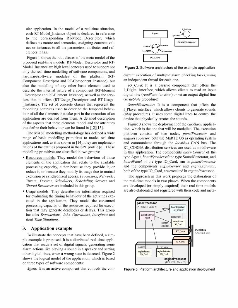
ple example is proposed. It is a distributed real-time appli-cation that reads a set of digital signals, generating somealarm actions like playing a sound in a speaker and settingother digital lines, when a wrong state is detected. Figure 2shows the logical model of the application, which is basedon three types of software components:
Agent: It is an active component that controls the con-
current execution of multiple alarm checking tasks, usingan independent thread for each one.
IO_Card: It is a passive component that offers theI_Digital interface, which allows clients to read an inputdigital line (readState function) or set an output digital line(writeState procedure).
SoundGenerator: It is a component that offers theI_Player interface, which allows clients to generate sounds(play procedure). It uses some digital lines to control thedevice that physically creates the sounds.
Figure 3 shows the deployment of the carAlarm applica-tion, which is the one that will be modelled. The executionplatform consists of two nodes, panelProcessor andengineProcessor, both use MaRTE OS as operating systemand communicate through the localBus CAN bus. TheRT_CORBA distribution services are used as middlewarein this application. The components alarmControl of thetype Agent, boardSpeaker of the type SoundGenerator, andboardPanel of the type IO_Card, run in panelProcessorand the components engineSensor and engineActuator,both of the type IO_Card, are executed in engineProcessor.
The approach in this work proposes the elaboration ofthe real-time models in two phases. When the componentsare developed (or simply acquired) their real-time modelsare also elaborated and registered with their code and meta-
1..n
1
1 speaker
instrument
actuator 0..n sensor
I_Digital
I_Player
IO_Card
SoundGenerator
Agent
1..n
1
1 speaker
instrument
actuator 0..n sensor
I_Digital
I_Player
IO_Card
SoundGenerator
Agent
Figure 2. Software architecture of the example application
Figure 3. Platform architecture and application deployment
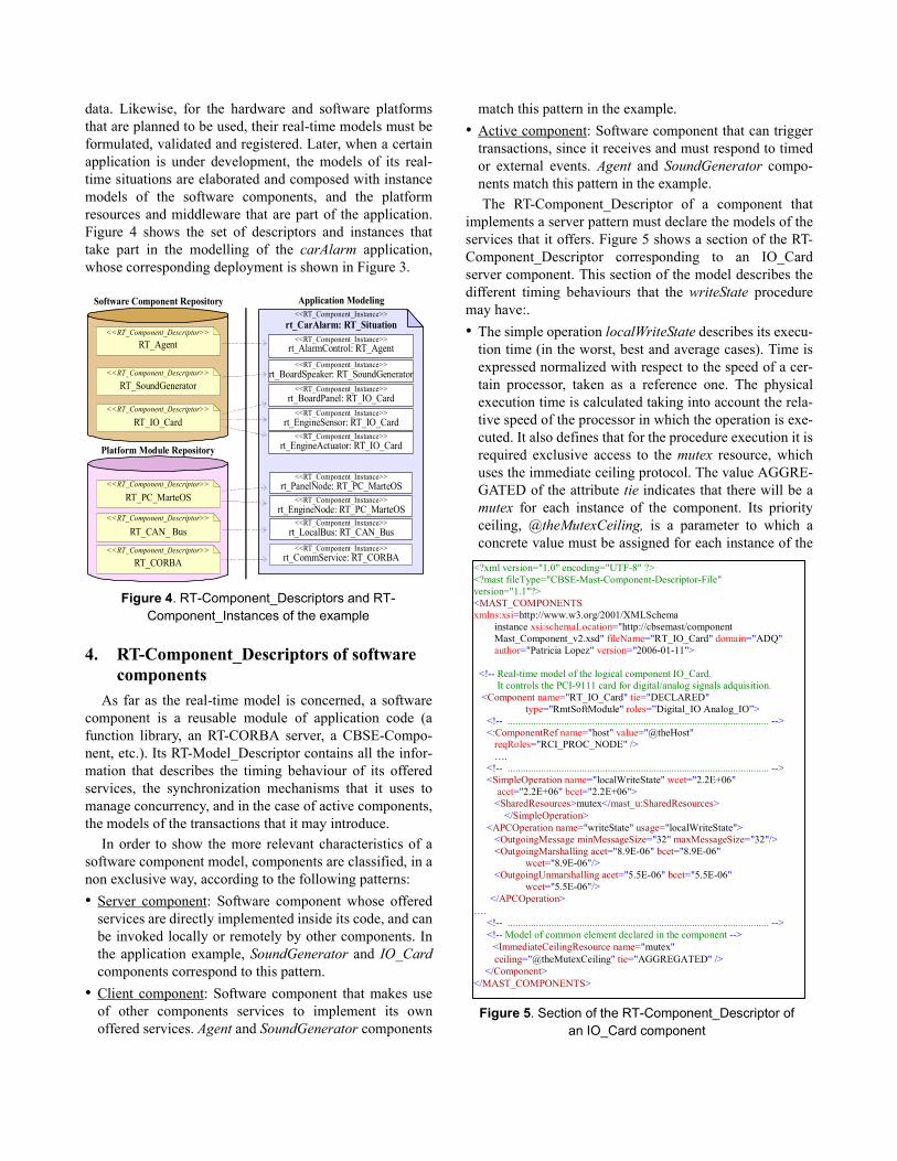
data. Likewise, for the hardware and software platformsthat are planned to be used, their real-time models must beformulated, validated and registered. Later, when a certainapplication is under development, the models of its real-time situations are elaborated and composed with instancemodels of the software components, and the platformresources and middleware that are part of the application.Figure 4 shows the set of descriptors and instances thattake part in the modelling of the carAlarm application,whose corresponding deployment is shown in Figure 3.
4. RT-Component_Descriptors of software components
As far as the real-time model is concerned, a softwarecomponent is a reusable module of application code (afunction library, an RT-CORBA server, a CBSE-Compo-nent, etc.). Its RT-Model_Descriptor contains all the infor-mation that describes the timing behaviour of its offeredservices, the synchronization mechanisms that it uses tomanage concurrency, and in the case of active components,the models of the transactions that it may introduce.
In order to show the more relevant characteristics of asoftware component model, components are classified, in anon exclusive way, according to the following patterns:• Server component: Software component whose offered
services are directly implemented inside its code, and canbe invoked locally or remotely by other components. Inthe application example, SoundGenerator and IO_Cardcomponents correspond to this pattern.
• Client component: Software component that makes useof other components services to implement its ownoffered services. Agent and SoundGenerator components
match this pattern in the example.• Active component: Software component that can trigger
transactions, since it receives and must respond to timedor external events. Agent and SoundGenerator compo-nents match this pattern in the example.The RT-Component_Descriptor of a component that
implements a server pattern must declare the models of theservices that it offers. Figure 5 shows a section of the RT-Component_Descriptor corresponding to an IO_Cardserver component. This section of the model describes thedifferent timing behaviours that the writeState proceduremay have:.• The simple operation localWriteState describes its execu-
tion time (in the worst, best and average cases). Time isexpressed normalized with respect to the speed of a cer-tain processor, taken as a reference one. The physicalexecution time is calculated taking into account the rela-tive speed of the processor in which the operation is exe-cuted. It also defines that for the procedure execution it isrequired exclusive access to the mutex resource, whichuses the immediate ceiling protocol. The value AGGRE-GATED of the attribute tie indicates that there will be amutex for each instance of the component. Its priorityceiling, @theMutexCeiling, is a parameter to which aconcrete value must be assigned for each instance of the
<<RT_Component_Descriptor>>
<<RT_Component_Descriptor>>
<<RT_Component_Descriptor>>
RT_Agent
RT_SoundGenerator
<<RT_Component_Descriptor>>
<<RT_Component_Descriptor>>
<<RT_Component_Descriptor>>
RT_CORBA
RT_CAN_ Bus
RT_PC_MarteOS
RT_IO_Card
<<RT_Component_Instance>>
<<RT_Component_Instance>>
<<RT_Component_Instance>>
<<RT_Component_Instance>>
<<RT_Component_Instance>>
<<RT_Component_Instance>>
<<RT_Component_Instance>>
<<RT_Component_Instance>>
<<RT_Component_Instance>>
<<RT_Component_Instance>>
rt_AlarmControl: RT_Agent
rt_CarAlarm: RT_Situation
rt_BoardSpeaker: RT_SoundGenerator
rt_LocalBus: RT_CAN_Bus
rt_CommService: RT_CORBA
rt_EngineNode: RT_PC_MarteOS
rt_PanelNode: RT_PC_MarteOS
rt_BoardPanel: RT_IO_Card
rt_EngineSensor: RT_IO_Card
rt_EngineActuator: RT_IO_Card
Application Modeling
Platform Module Repository
Software Component Repository
Figure 4. RT-Component_Descriptors and RT-Component_Instances of the example
<?xml version="1.0" encoding="UTF-8" ?> <?mast fileType="CBSE-Mast-Component-Descriptor-File" version="1.1"?> <MAST_COMPONENTS xmlns:xsi=http://www.w3.org/2001/XMLSchema
instance xsi:schemaLocation="http://cbsemast/component Mast_Component_v2.xsd" fileName="RT_IO_Card" domain="ADQ" author="Patricia Lopez" version="2006-01-11">
<!-- Real-time model of the logical component IO_Card.
It controls the PCI-9111 card for digital/analog signals adquisition. <Component name="RT_IO_Card" tie="DECLARED"
type="RmtSoftModule" roles=”Digital_IO Analog_IO”> <!-- ...................................................................................................... --> <:ComponentRef name="host" value="@theHost"
reqRoles="RCI_PROC_NODE" /> ….
<!-- ...................................................................................................... --> <SimpleOperation name="localWriteState" wcet="2.2E+06"
acet="2.2E+06" bcet="2.2E+06"> <SharedResources>mutex</mast_u:SharedResources>
</SimpleOperation> <APCOperation name="writeState" usage="localWriteState">
<OutgoingMessage minMessageSize="32" maxMessageSize="32"/> <OutgoingMarshalling acet="8.9E-06" bcet="8.9E-06"
wcet="8.9E-06"/> <OutgoingUnmarshalling acet="5.5E-06" bcet="5.5E-06"
wcet="5.5E-06"/> </APCOperation> …. <!-- ...................................................................................................... --> <!-- Model of common element declared in the component --> <ImmediateCeilingResource name="mutex"
ceiling="@theMutexCeiling" tie="AGGREGATED" /> </Component> </MAST_COMPONENTS>
Figure 5. Section of the RT-Component_Descriptor of an IO_Card component
component. This model is sufficient when the procedureis invoked locally.
• The asynchronous procedure call (APCOperation) writ-eState extends the model of the simple operation with theinformation required to model the timing behaviour of aremote invocation of the procedure. It describes only theinformation that is consequence of the procedure nature,like the messages length (due to the size of the argu-ments) and the overheads introduced by the marshallingand unmarshalling operations (used to serialize the argu-ments to send them through the network).@theHost is a parameter that references the model of
the processor node in which the instance of the componentis installed and executed, and it must be present in the real-time model of any software component. It allows to accessthe basic characteristics of the processor (processing speed,scheduler nature, timer resolution, etc.). Access to them isrequired by the tools that process the model in order toevaluate the response times of the transactions that use anyof the services offered by the component.
The RT-Component_Descriptor of a component thatimplements a client pattern, and consequently requiresother components to implement its functionality, mustinclude parametric references to the real-time models ofthese required server components. These references allowthe tools to access the models of the server components inorder to evaluate the response times of the services offeredby the client component. To consider the case in which theaccess to the server is remote, the descriptors include addi-tional parameters to refer to the communication networkand protocol models used in the invocation of the service.
Figure 6 shows a section of the RT-Component_Descriptor of an Agent component type. The parameter@usedSpeaker is defined to make reference to the model of
the component to which the Agent will access with the rolespeaker. For the case in which the client and the server arein different processors, the descriptor includes parametersto refer to the communication network model (@theCom-mNetwork) and the communication middleware (@used-SpeakerAccess) used to invoke the service. Acommunication network model describes its bandwidth,the messages granularity, the characteristics of the sched-uler that manages messages transmission, the processingcapacity required to the processors by the drivers, and theoverhead due to synchronization protocol messages amongnodes. The middleware model describes the sequence ofactivities that represents the internal code executedbetween the service invocation made by the client and theexecution of the method in the server. This sequence hastwo alternative models, one for local invocations andanother for remote calls.
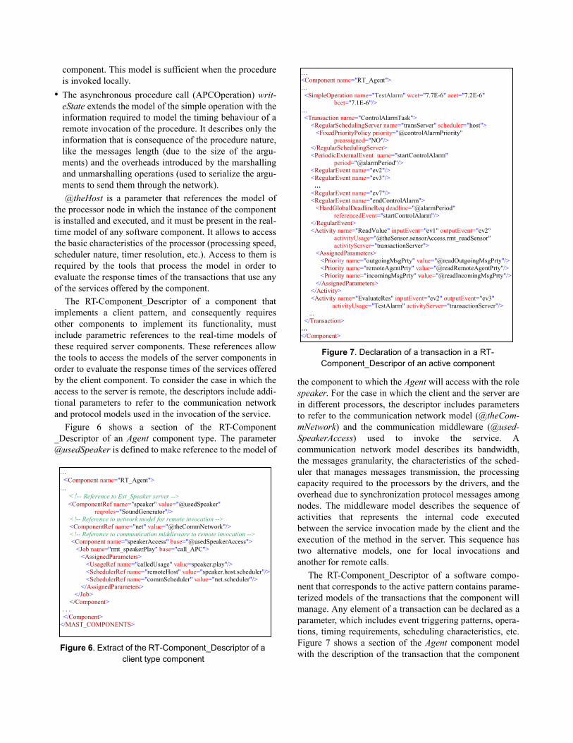
The RT-Component_Descriptor of a software compo-nent that corresponds to the active pattern contains parame-terized models of the transactions that the component willmanage. Any element of a transaction can be declared as aparameter, which includes event triggering patterns, opera-tions, timing requirements, scheduling characteristics, etc.Figure 7 shows a section of the Agent component modelwith the description of the transaction that the component
Figure 6. Extract of the RT-Component_Descriptor of a client type component
… <Component name="RT_Agent"> … <!-- Reference to Ext_Speaker server -->
<ComponentRef name="speaker" value="@usedSpeaker" reqroles="SoundGenerator"/>
<!-- Reference to network model for remote invocation --> <ComponentRef name="net" value="@theCommNetwork"/> <!-- Reference to communication middleware to remote invocation --> <Component name="speakerAccess" base="@usedSpeakerAccess"> <Job name="rmt_speakerPlay" base="call_APC"> <AssignedParameters> <UsageRef name="calledUsage" value=speaker.play"/> <SchedulerRef name="remoteHost" value="speaker.host.scheduler"/> <SchedulerRef name="commScheduler" value="net.scheduler"/> </AssignedParameters> </Job> </Component> . . . </Component> </MAST_COMPONENTS>
… <Component name="RT_Agent"> … <SimpleOperation name="TestAlarm" wcet="7.7E-6" acet="7.2E-6"
bcet="7.1E-6"/> … <Transaction name="ControlAlarmTask"> <RegularSchedulingServer name="transServer" scheduler="host"> <FixedPriorityPolicy priority="@controlAlarmPriority"
preassigned="NO"/> </RegularSchedulingServer> <PeriodicExternalEvent name="startControlAlarm"
period="@alarmPeriod"/> <RegularEvent name="ev2"/> <RegularEvent name="ev3"/> … <RegularEvent name="ev7"/> <RegularEvent name="endControlAlarm"> <HardGlobalDeadlineReq deadline="@alarmPeriod" referencedEvent="startControlAlarm"/> </RegularEvent> <Activity name="ReadValue" inputEvent="ev1" outputEvent="ev2"
activityUsage="@theSensor.sensorAccess.rmt_readSensor" activityServer="transactionServer">
<AssignedParameters> <Priority name="outgoingMsgPrty" value="@readOutgoingMsgPrty"/> <Priority name="remoteAgentPrty" value="@readRemoteAgentPrty"/> <Priority name="incomingMsgPrty" value="@readIncomingMsgPrty"/> </AssignedParameters> </Activity> <Activity name="EvaluateRes" inputEvent="ev2" outputEvent="ev3" activityUsage="TestAlarm" activityServer="transactionServer"/> ... </Transaction> … </Component>
Figure 7. Declaration of a transaction in a RT-Component_Descripor of an active component
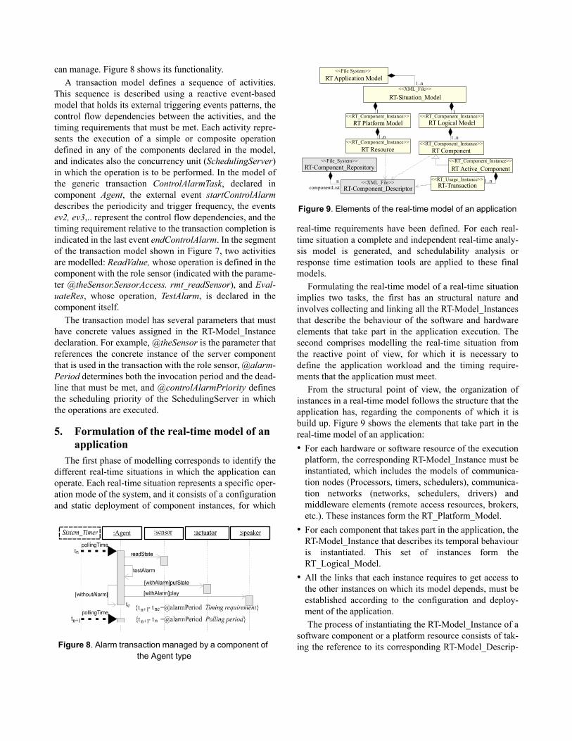
can manage. Figure 8 shows its functionality.A transaction model defines a sequence of activities.
This sequence is described using a reactive event-basedmodel that holds its external triggering events patterns, thecontrol flow dependencies between the activities, and thetiming requirements that must be met. Each activity repre-sents the execution of a simple or composite operationdefined in any of the components declared in the model,and indicates also the concurrency unit (SchedulingServer)in which the operation is to be performed. In the model ofthe generic transaction ControlAlarmTask, declared incomponent Agent, the external event startControlAlarmdescribes the periodicity and trigger frequency, the eventsev2, ev3,.. represent the control flow dependencies, and thetiming requirement relative to the transaction completion isindicated in the last event endControlAlarm. In the segmentof the transaction model shown in Figure 7, two activitiesare modelled: ReadValue, whose operation is defined in thecomponent with the role sensor (indicated with the parame-ter @theSensor.SensorAccess. rmt_readSensor), and Eval-uateRes, whose operation, TestAlarm, is declared in thecomponent itself.
The transaction model has several parameters that musthave concrete values assigned in the RT-Model_Instancedeclaration. For example, @theSensor is the parameter thatreferences the concrete instance of the server componentthat is used in the transaction with the role sensor, @alarm-Period determines both the invocation period and the dead-line that must be met, and @controlAlarmPriority definesthe scheduling priority of the SchedulingServer in whichthe operations are executed.
5. Formulation of the real-time model of an application
The first phase of modelling corresponds to identify thedifferent real-time situations in which the application canoperate. Each real-time situation represents a specific oper-ation mode of the system, and it consists of a configurationand static deployment of component instances, for which
real-time requirements have been defined. For each real-time situation a complete and independent real-time analy-sis model is generated, and schedulability analysis orresponse time estimation tools are applied to these finalmodels.
Formulating the real-time model of a real-time situationimplies two tasks, the first has an structural nature andinvolves collecting and linking all the RT-Model_Instancesthat describe the behaviour of the software and hardwareelements that take part in the application execution. Thesecond comprises modelling the real-time situation fromthe reactive point of view, for which it is necessary todefine the application workload and the timing require-ments that the application must meet.
From the structural point of view, the organization ofinstances in a real-time model follows the structure that theapplication has, regarding the components of which it isbuild up. Figure 9 shows the elements that take part in thereal-time model of an application:• For each hardware or software resource of the execution
platform, the corresponding RT-Model_Instance must beinstantiated, which includes the models of communica-tion nodes (Processors, timers, schedulers), communica-tion networks (networks, schedulers, drivers) andmiddleware elements (remote access resources, brokers,etc.). These instances form the RT_Platform_Model.
• For each component that takes part in the application, theRT-Model_Instance that describes its temporal behaviouris instantiated. This set of instances form theRT_Logical_Model.
• All the links that each instance requires to get access tothe other instances on which its model depends, must beestablished according to the configuration and deploy-ment of the application.The process of instantiating the RT-Model_Instance of a
software component or a platform resource consists of tak-ing the reference to its corresponding RT-Model_Descrip-Figure 8. Alarm transaction managed by a component of
the Agent type
n
1 1
componentList RT-Component_Descriptor
RT-Component_Repository
RT-Situation_Model<<XML_File>>
<<RT_Component_Instance>> <<RT_Component_Instance>>
<<RT_Component_Instance>>
<<RT_Component_Instance>><<RT_Component_Instance>>
RT Application Model<<File System>>
<<XML_File>>
<<File_System>>
1..n
1..n
1..n 1..n
RT-Transaction
RT Logical ModelRT Platform Model
RT Resource RT Component
RT Active_Component<<RT_Usage_Instance>>
Figure 9. Elements of the real-time model of an application
tor, and considering the application context, assigningconcrete values to its parameters.
The workload in the real-time model of an application isdetermined by the set of transactions that its active compo-nents declare. The activation patterns that trigger them maybe deterministic or defined through the statistical distribu-tion of the interarrival times between consecutive trigger-ing events. They also provide references for defining theglobal timing requirements.
There are two types of transaction instances. On the onehand, those defined as <<Aggregated>> are inherent to themodel of the component and are automatically attached toits instance model, so the designer do not have to declarethem explicitly in the real-time situation model. On theother hand, those transactions that depend on the applica-tion workload, as a consequence of the input data or theapplication configuration, are defined as <<Declared>> inthe active component models. The number of instances ofthese transactions present in the system and the concretevalues assigned to their parameters must be explicitlyestablished by the designer in the real-time situation model.
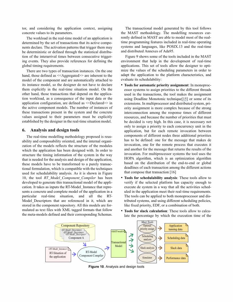
6. Analysis and design toolsThe real-time modelling methodology proposed is reus-
ability and composability oriented, and the internal organi-zation of the models reflects the structure of the moduleswhich the application has been designed with. In order tostructure the timing information of the system in the waythat is needed for the analysis and design of the application,these models have to be transformed to a purely transac-tional formulation, which is compatible with the techniquesused for schedulability analysis. As it is shown in Figure10, the tool RT_Model_Component_Compiler has beendeveloped to generate this transactional model of the appli-cation. It takes as inputs the RT-Model_Instance that repre-sents a concrete and complete model of the application in aparticular real-time situation, and all the RT-Model_Descriptors that are referenced in it, which arestored in the component repository. All this models are for-mulated as text files with XML tagged formats that followthe meta-models defined and their corresponding Schemas.
The transactional model generated by this tool followsthe MAST methodology. The modelling resources cur-rently defined in MAST are able to model most of the real-time programming features included in real-time operatingsystems and languages, like POSIX.13 and the real-timeand distributed Annexes of Ada95.
Figure 9 shows some of the tools included in the MASTenvironment that help in the development of real-timeapplications. This set of tools allow the designer to opti-mize the values of the scheduling parameters in order toadapt the application to the platform characteristics, andevaluate its schedulability:• Tools for automatic priority assignment: In monoproc-
essor systems to assign priorities to the different threadsused in the transactions, the tool makes the assignmentusing Deadline Monotonic technique[15] or some of itsextensions. In multiprocessor and distributed system, pri-ority assignment is more complex because of the stronginterconnection among the response times of differentresources, and because the number of priorities that mustbe decided is very high. In this case, it is necessary notonly to assign a priority to each concurrency unit in theapplication, but for each remote invocation betweencomponents of different nodes three additional prioritieshas to be defined: one for the message that makes deinvocation, one for the remote process that executes itand another for the message that returns the results of theinvocation. For multiprocessor systems the tool uses theHOPA algorithm, which is an optimization algorithmbased on the distribution of the end-to-end or globaldeadlines of each transaction among the different actionsthat compose that transaction [16]
• Tools for schedulability analysis: These tools allow toverify if the selected platform has capacity enough toexecute de system in a way that all the activities sched-uled in the application meet their real-time requirements.The tools can be applied to both monoprocessor and dis-tributed systems, and using different scheduling policies,like fixed priority, EDF, or a combination of both.
• Tools for slack calculation: These tools allow to calcu-late the percentage by which the execution time of the
Component Repository« »RT-Model_Descriptor« »RT-Model_Descriptor« »RT-Model_Descriptor
« »RT-Model_Instance
Component A
RT-Situation ofthe application
RT-ModelComponent Compiler
TransactionalModel
« »MAST-model
Mast ToolsOptimal
priority assign
Schedulinganalysis
Simulator
Slack analysis
Applicationtunning data
Scheduling data
Slack data
Performance data
Figure 10. Analysis and design tools
operations may be increased while keeping the systemschedulable, or that in which they must be decreased toget the system schedulable.
• Tools for statistical estimation of performance: Thesetools evaluate by simulation the average performance ofthe system and are particularly useful in applications thatcombine soft and hard real-time requirements.
7. Conclusions and Future WorkThis work describes a methodology to formulate the
real-time model of an application, which has the composa-bility properties needed to generate the real-time model ofa complex system by the composition of the individualreal-time models of the software and hardware componentsthat forms it.
This paper introduces the RT-Model_Descriptor conceptas a general real-time behaviour model for reusable soft-ware components, like subsystems, commercial off-the-shelf software or even a hardware processing device, anoperating system platform or a network. It does it as anindependent entity, in a way that allows the automated con-struction of the final analyzable model by a tool with plas-ticity and composability properties similar to those used inthe construction of the application.
The key in this methodology is the application of bothconcepts, descriptor and instance, in the real-time model-ling of components. The RT-Component_Descriptor is aparameterized consistent form, which holds the completereal-time data of a component disregarding the applicationsin which it may be used. It includes all the internal ele-ments of the model, and leaves the "blanks" to be filledwith references to the concrete models of components thataffect its behaviour. The RT-Component_Instance is thefinal real-time model of a component instance in the con-text of a concrete application. It is to be built by a tool afterall the necessary components in the real-time situation areknown.
The methodology has been successfully applied in thereal-time modelling of a set of components designed forthe development of industrial controllers and the automa-tion of production lines using real-time POSIX OS, CANBus, real-time protocols on Ethernet, Ada95 andRT_CORBA software technologies.
Further work will explore the future MARTE [18] UML2.0 based profile, for more precise constructs to hold andtreat real-time models with standard UML CASE tools.
References[1] H. Kopetz, R. Zainlinger, G. Fohler, H. Kantz, P. Puschner,
and W. Schutz, ”The design of real-time systems: fromspecification to implementation and verification” SoftwareEngineering Journal, Vol.6 , no. 3, pp. 72-82. May, 1991.
[2] J. Liu, Real-Time Systems. ISBN 0-13-099651-3. PrenticeHall Inc., 2000.
[3] M. Klein, T. Ralya, B. Pollak, R. Obenza, and M. GonzálezHarbour, A Practitioner's Handbook for Real-Time SystemsAnalysis, Kluwer Academic Pub., 1993.
[4] A. Cheng, “Real-time Systems Scheduling, Analysis andVerification”. ISBN 0-471-18406-3. J. Wiley & Sons, 2002
[5] IEEE Std 1003.13TM-2003: ”IEEE Standard for InformationTechnology-Standarized Application Environment Profile(AEP)-POSIXR Realtime and Embedded ApplicationSupport”, 2003.
[6] Object Management Group: "UML Profile for Schedulability,Performance and Time Specification", Version 1.1. OMGdocument formal/05-01-02, January, 2005.
[7] A. Burns and A.Wellings. "HRT-HOOD: a Structured DesignMethod for Hard Real-Time Ada Systems", volume 3 of Real-Time Safety Critical Systems. Elsevier, 1995.
[8] H. Gomaa. Designing Concurrent, Distributed, and Real-TimeApplications with UML. Addison-Wesley, 2000
[9] H.Kopetz and N.Suri:“Compositional design of RT-Systems:A Conceptual basis for specification of linking interfaces” 6thIEEE Int. Symp. of Object-oriented Real-time DistributedComputing (ISORT03). Hakodate (Japan). May, 2003.
[10]A. Tesanovic, D. Nyström, J. Hansson, and C. Norström:"Aspects and Components in Real-Time SystemDevelopment: Towards Reconfigurable and ReusableSoftware". Journal of Embedded Computing, February, 2004.
[11]M. González Harbour, J.J. Gutiérrez, J.C.Palencia andJ.M.Drake: "MAST: Modeling and Analysis Suite for Real-Time Applications" Proc. of the Euromicro Conference onReal-Time Systems, June 2001.
[12].J.L. Medina, M.González Harbour, J.M. Drake: "MASTReal-time View: A Graphic UML Tool for ModelingObject_Oriented Real_Time Systems", RTSS, Dec, 2001.
[13]MAST: Modeling and Analysis Suite for Real-TimeApplications. “http://mast.unican.es
[14]J.L. Medina: ”Metodología y herramientas UML para elmodelado y análisis de sistemas de tiempo real orientados aobjetos”. PhD Thesis (In Spanish), Santander (Spain), 2005.
[15]C.L. Liu and J.W. Laylan: “Scheduling Algorithms forMultiprogramming in a Hard Real-time Enviroment” J. Of theACM, Vol. 29, No 1,pp46-61, 1973.
[16]JJ. Gutiérrez and M. González Harbour: “Optimized PriorityAssignment for Task and Message in Distributed Real-TimeSystems”. Proceedings of the 3rd Workshop on Parallel andDistributed Real-time Systems, Santa Barbara (USA), 1995.
[17]E. Bondarev, P. de With, M.Chaudron, and J. Muskens:“Modelling of Input-Parameter Dependency for PerformancePredictions of Component-Based Embeded Systems”. Proc.of Euromicro SEAA, IEEE Computer Society Press 2005.
[18]Object Management Group: UML Profile for Modeling andAnalysis of Real-Time and Embedded systems (MARTE),RFP. 2005. OMG document: realtime/05-02-06